Embed Size (px)
Citation preview

Chipsmall Limited consists of a professional team with an average of over 10 year of expertise in the distribution
of electronic components. Based in Hongkong, we have already established firm and mutual-benefit business
relationships with customers from,Europe,America and south Asia,supplying obsolete and hard-to-find components
to meet their specific needs.
With the principle of “Quality Parts,Customers Priority,Honest Operation,and Considerate Service”,our business
mainly focus on the distribution of electronic components. Line cards we deal with include
Microchip,ALPS,ROHM,Xilinx,Pulse,ON,Everlight and Freescale. Main products comprise
IC,Modules,Potentiometer,IC Socket,Relay,Connector.Our parts cover such applications as commercial,industrial,
and automotives areas.
We are looking forward to setting up business relationship with you and hope to provide you with the best service
and solution. Let us make a better world for our industry!
Contact usTel: +86-755-8981 8866 Fax: +86-755-8427 6832
Email & Skype: [email protected] Web: www.chipsmall.com
Address: A1208, Overseas Decoration Building, #122 Zhenhua RD., Futian, Shenzhen, China
CSM_H8PS_DS_E_6_2
1
Cam Positioner
H8PS
This Compact Cam Positioner, Popular for Its Ease-of-use, Now Comes with Even Better Functions.
• Compact 8-, 16-, and 32-output Models available that are 1/4-DIN size at 96 x 96 mm.
• High-speed operation at 1,600 r/min and high-precision settings to 0.5° ensure widespread application.
• Highly visible display with backlit negative transmissive LCD.
• Advance angle compensation function to compensate for output delays.
• Bank function for multi-product production (8 banks). (H8PS-16@/-32@ models.)
• Speed display and pulse output.
• Approved standards: UL/CSA and EMC.Refer to Safety Precautions for All Counters and Safety Precautions on page 18 and 19.
Features
Models with 8, 16, or 32 Outputs
The lineup includes Models with 32 outputs in a compact 1/4-DIN size. Using the optional Parallel Input Adapter (Y92C-30) enables expanding to up to 64 outputs for one encoder to support anything from a simple positioning application to a large-scale system.
Simple Programming
The programming method is designed based on a one key-one action concept for settings that could not be simpler. Both initial settings and factory adjustments are effort-free.
Large, Backlit Negative LCDs
Large LCDs, red for the process value and green for set values, show a wealth of operation information, making operating status visible at a glance.
High Speed Up To 1,600 r/minHigh Precision Up To 0.5° (at 720 Resolution)
High-speed, high-precision applications can be easily handled and productivity increased.
Bank Function for Multi-product Production
Up to eight different programs can be registered in advance to enable fast and easy switching between products (16/32-output Models only).
USB Communications for Easy Setting from a Computer
Optional Support Software can be used to enable programming from a personal computer via USB communications. Programs can be easily copied, saved, printed, and much more.
Speed Display and Speed Alarm Output
Both the speed (rotations/minutes) and present angular position can be displayed at the same time. Alarm outputs can be produced for both upper and lower speed limits.
Advance Angle Compensation Function to Compensate for Output Delays
The advance angle compensation (ADV) function automatically advances the ON/OFF angle of outputs in proportion to machine (encoder) speed to compensate for the delay in timing of ON/OFF operation. ADV values can be set individually for 7 cam outputs.
Pulse Output for Timing Control
The number of pulses per rotation and the pulse output start angle can be set to enable operations like adjusting timing with a PLC or outputting to a rotation meter.
8-output Models 16-output Models 32-output Models
96 mm
96 mm CAM STEP
1 2 7
RUN
CAM STEP
1 2 7
RUN
Switchable
Present angular position
Speed
Speed
Present angular position
Speed
Upper limit alarm output
Lower limit alarm output
Upper limit
Lower limit
Errors
Cam program settings
100°8° compensation
180°
92° 172°
At high-speed (400 r/min)
Pulse outputPLC
Rotation meter
H8PS
2
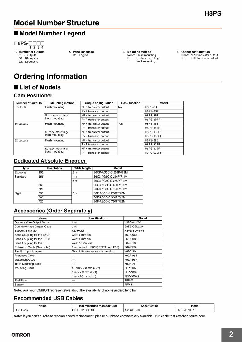
Model Number Structure
■ Model Number Legend
Ordering Information
■ List of Models
Cam Positioner
Dedicated Absolute Encoder
Accessories (Order Separately)
Note: Ask your OMRON representative about the availability of non-standard lengths.
Recommended USB Cables
Note: If you can’t purchase recommended replacement, please purchase commercially available USB cable that attached ferrite core.
1 2 3 4H8PS-@@@@
1. Number of outputs8: 8 outputs 16: 16 outputs 32: 32 outputs
2. Panel language B: English
3. Mounting method None: Flush mountingF: Surface mounting/
track mounting
4. Output configuration None: NPN transistor output P: PNP transistor output
Number of outputs Mounting method Output configuration Bank function Model
8 outputs Flush mounting NPN transistor output No H8PS-8B
PNP transistor output H8PS-8BP
Surface mounting/track mounting
NPN transistor output H8PS-8BF
PNP transistor output H8PS-8BFP
16 outputs Flush mounting NPN transistor output Yes H8PS-16B
PNP transistor output H8PS-16BP
Surface mounting/track mounting
NPN transistor output H8PS-16BF
PNP transistor output H8PS-16BFP
32 outputs Flush mounting NPN transistor output H8PS-32B
PNP transistor output H8PS-32BP
Surface mounting/track mounting
NPN transistor output H8PS-32BF
PNP transistor output H8PS-32BFP
Type Resolution Cable length Model
Economy 256 2 m E6CP-AG5C-C 256P/R 2M
Standard 256 1 m E6C3-AG5C-C 256P/R 1M
2 m E6C3-AG5C-C 256P/R 2M
360 E6C3-AG5C-C 360P/R 2M
720 E6C3-AG5C-C 720P/R 2M
Rigid 256 2 m E6F-AG5C-C 256P/R 2M
360 E6F-AG5C-C 360P/R 2M
720 E6F-AG5C-C 720P/R 2M
Name Specification Model
Discrete Wire Output Cable 2 m Y92S-41-200
Connector-type Output Cable 2 m E5ZE-CBL200
Support Software CD-ROM H8PS-SOFT-V1
Shaft Coupling for the E6CP Axis: 6 mm dia. E69-C06B
Shaft Coupling for the E6C3 Axis: 8 mm dia. E69-C08B
Shaft Coupling for the E6F Axis: 10 mm dia. E69-C10B
Extension Cable (See note.) 5 m (same for E6CP, E6C3, and E6F) E69-DF5
Parallel Input Adapter Two Units can operate in parallel. Y92C-30
Protective Cover --- Y92A-96B
Watertight Cover --- Y92A-96N
Track Mounting Base --- Y92F-91
Mounting Track 50 cm × 7.3 mm (l × t) PFP-50N
1 m × 7.3 mm (l × t) PFP-100N
1 m × 16 mm (l × t) PFP-100N2
End Plate --- PFP-M
Spacer --- PFP-S
Name Recommended manufacturer Specification Model
USB Cable ELECOM CO.Ltd. A-miniB, 2m U2C-MF20BK
H8PS
3
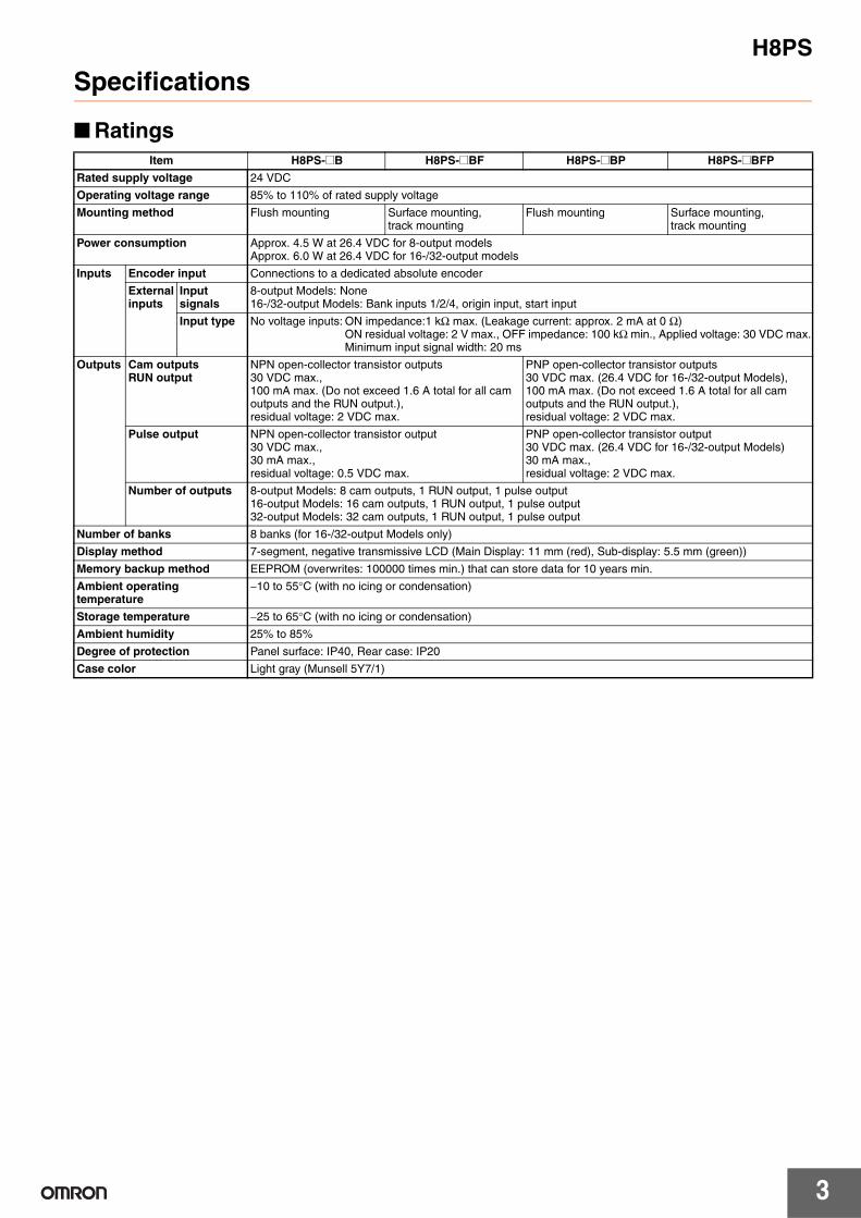
Specifications
■ Ratings
Item H8PS-@B H8PS-@BF H8PS-@BP H8PS-@BFP
Rated supply voltage 24 VDC
Operating voltage range 85% to 110% of rated supply voltage
Mounting method Flush mounting Surface mounting, track mounting
Flush mounting Surface mounting, track mounting
Power consumption Approx. 4.5 W at 26.4 VDC for 8-output modelsApprox. 6.0 W at 26.4 VDC for 16-/32-output models
Inputs Encoder input Connections to a dedicated absolute encoder
External inputs
Input signals
8-output Models: None16-/32-output Models: Bank inputs 1/2/4, origin input, start input
Input type No voltage inputs: ON impedance:1 kΩ max. (Leakage current: approx. 2 mA at 0 Ω)ON residual voltage: 2 V max., OFF impedance: 100 kΩ min., Applied voltage: 30 VDC max.Minimum input signal width: 20 ms
Outputs Cam outputsRUN output
NPN open-collector transistor outputs 30 VDC max., 100 mA max. (Do not exceed 1.6 A total for all cam outputs and the RUN output.), residual voltage: 2 VDC max.
PNP open-collector transistor outputs30 VDC max. (26.4 VDC for 16-/32-output Models), 100 mA max. (Do not exceed 1.6 A total for all cam outputs and the RUN output.), residual voltage: 2 VDC max.
Pulse output NPN open-collector transistor output 30 VDC max., 30 mA max., residual voltage: 0.5 VDC max.
PNP open-collector transistor output 30 VDC max. (26.4 VDC for 16-/32-output Models)30 mA max., residual voltage: 2 VDC max.
Number of outputs 8-output Models: 8 cam outputs, 1 RUN output, 1 pulse output 16-output Models: 16 cam outputs, 1 RUN output, 1 pulse output 32-output Models: 32 cam outputs, 1 RUN output, 1 pulse output
Number of banks 8 banks (for 16-/32-output Models only)
Display method 7-segment, negative transmissive LCD (Main Display: 11 mm (red), Sub-display: 5.5 mm (green))
Memory backup method EEPROM (overwrites: 100000 times min.) that can store data for 10 years min.
Ambient operating temperature
−10 to 55°C (with no icing or condensation)
Storage temperature −25 to 65°C (with no icing or condensation)
Ambient humidity 25% to 85%
Degree of protection Panel surface: IP40, Rear case: IP20
Case color Light gray (Munsell 5Y7/1)
H8PS
4
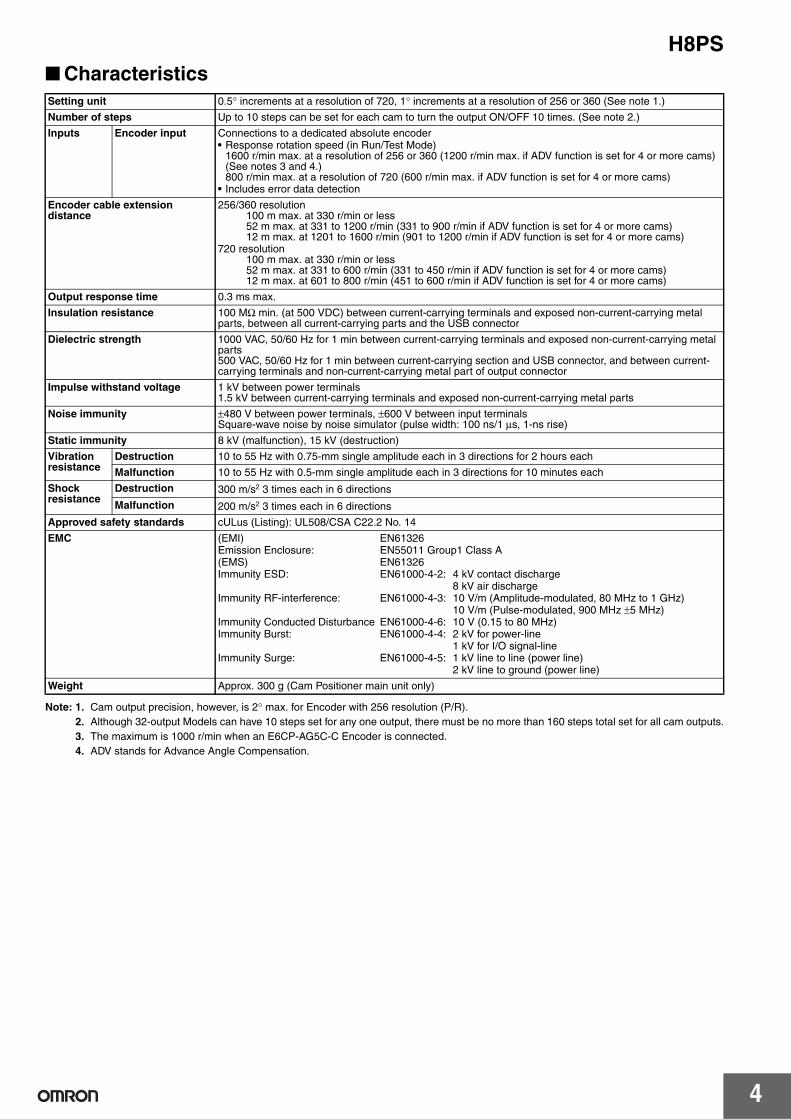
■ Characteristics
Note: 1. Cam output precision, however, is 2° max. for Encoder with 256 resolution (P/R).
2. Although 32-output Models can have 10 steps set for any one output, there must be no more than 160 steps total set for all cam outputs.
3. The maximum is 1000 r/min when an E6CP-AG5C-C Encoder is connected.
4. ADV stands for Advance Angle Compensation.
Setting unit 0.5° increments at a resolution of 720, 1° increments at a resolution of 256 or 360 (See note 1.)
Number of steps Up to 10 steps can be set for each cam to turn the output ON/OFF 10 times. (See note 2.)
Inputs Encoder input Connections to a dedicated absolute encoder • Response rotation speed (in Run/Test Mode)
1600 r/min max. at a resolution of 256 or 360 (1200 r/min max. if ADV function is set for 4 or more cams) (See notes 3 and 4.)800 r/min max. at a resolution of 720 (600 r/min max. if ADV function is set for 4 or more cams)
• Includes error data detection
Encoder cable extension distance
256/360 resolution100 m max. at 330 r/min or less52 m max. at 331 to 1200 r/min (331 to 900 r/min if ADV function is set for 4 or more cams)12 m max. at 1201 to 1600 r/min (901 to 1200 r/min if ADV function is set for 4 or more cams)
720 resolution100 m max. at 330 r/min or less52 m max. at 331 to 600 r/min (331 to 450 r/min if ADV function is set for 4 or more cams)12 m max. at 601 to 800 r/min (451 to 600 r/min if ADV function is set for 4 or more cams)
Output response time 0.3 ms max.
Insulation resistance 100 MΩ min. (at 500 VDC) between current-carrying terminals and exposed non-current-carrying metal parts, between all current-carrying parts and the USB connector
Dielectric strength 1000 VAC, 50/60 Hz for 1 min between current-carrying terminals and exposed non-current-carrying metal parts500 VAC, 50/60 Hz for 1 min between current-carrying section and USB connector, and between current-carrying terminals and non-current-carrying metal part of output connector
Impulse withstand voltage 1 kV between power terminals1.5 kV between current-carrying terminals and exposed non-current-carrying metal parts
Noise immunity ±480 V between power terminals, ±600 V between input terminals Square-wave noise by noise simulator (pulse width: 100 ns/1 µs, 1-ns rise)
Static immunity 8 kV (malfunction), 15 kV (destruction)
Vibration resistance
Destruction 10 to 55 Hz with 0.75-mm single amplitude each in 3 directions for 2 hours each
Malfunction 10 to 55 Hz with 0.5-mm single amplitude each in 3 directions for 10 minutes each
Shock resistance
Destruction 300 m/s2 3 times each in 6 directions
Malfunction 200 m/s2 3 times each in 6 directions
Approved safety standards cULus (Listing): UL508/CSA C22.2 No. 14
EMC (EMI) EN61326Emission Enclosure: EN55011 Group1 Class A(EMS) EN61326Immunity ESD: EN61000-4-2: 4 kV contact discharge
8 kV air discharge Immunity RF-interference: EN61000-4-3: 10 V/m (Amplitude-modulated, 80 MHz to 1 GHz)
10 V/m (Pulse-modulated, 900 MHz ±5 MHz) Immunity Conducted Disturbance EN61000-4-6: 10 V (0.15 to 80 MHz)Immunity Burst: EN61000-4-4: 2 kV for power-line
1 kV for I/O signal-lineImmunity Surge: EN61000-4-5: 1 kV line to line (power line)
2 kV line to ground (power line)
Weight Approx. 300 g (Cam Positioner main unit only)
H8PS
5
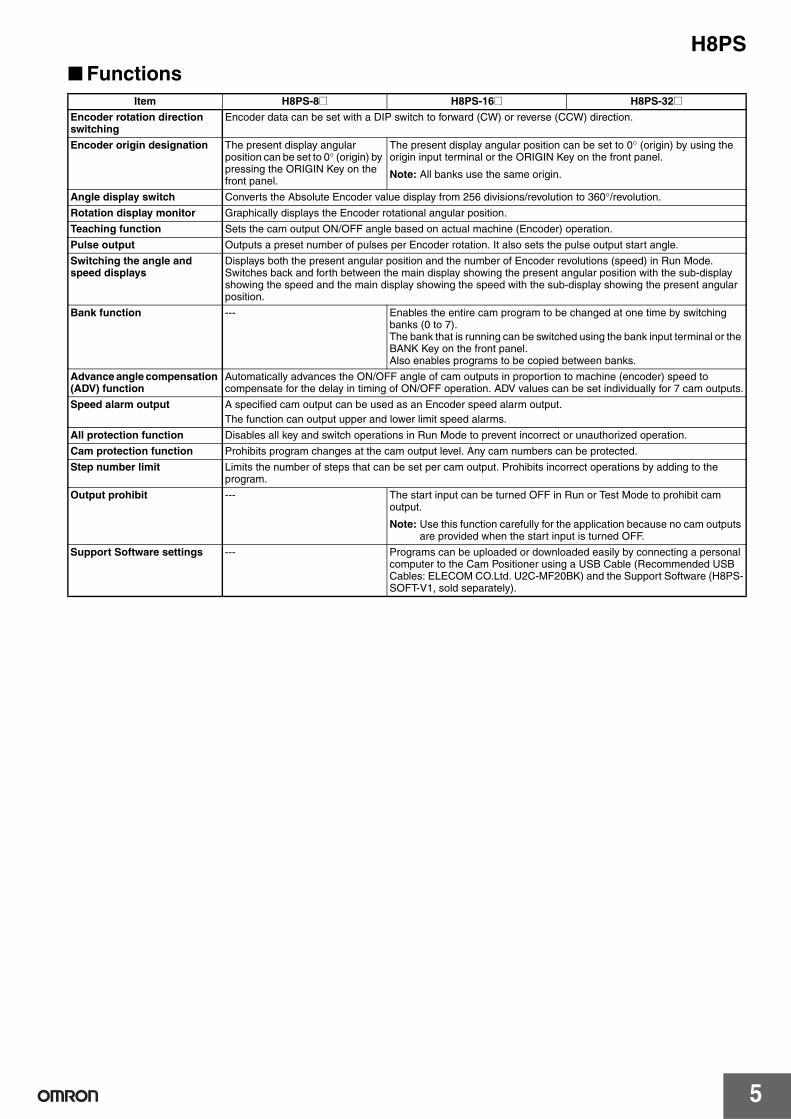
■ Functions
Item H8PS-8@ H8PS-16@ H8PS-32@
Encoder rotation direction switching
Encoder data can be set with a DIP switch to forward (CW) or reverse (CCW) direction.
Encoder origin designation The present display angular position can be set to 0° (origin) by pressing the ORIGIN Key on the front panel.
The present display angular position can be set to 0° (origin) by using the origin input terminal or the ORIGIN Key on the front panel.
Note: All banks use the same origin.
Angle display switch Converts the Absolute Encoder value display from 256 divisions/revolution to 360°/revolution.
Rotation display monitor Graphically displays the Encoder rotational angular position.
Teaching function Sets the cam output ON/OFF angle based on actual machine (Encoder) operation.
Pulse output Outputs a preset number of pulses per Encoder rotation. It also sets the pulse output start angle.
Switching the angle and speed displays
Displays both the present angular position and the number of Encoder revolutions (speed) in Run Mode.Switches back and forth between the main display showing the present angular position with the sub-display showing the speed and the main display showing the speed with the sub-display showing the present angular position.
Bank function --- Enables the entire cam program to be changed at one time by switching banks (0 to 7).The bank that is running can be switched using the bank input terminal or the BANK Key on the front panel.Also enables programs to be copied between banks.
Advance angle compensation (ADV) function
Automatically advances the ON/OFF angle of cam outputs in proportion to machine (encoder) speed to compensate for the delay in timing of ON/OFF operation. ADV values can be set individually for 7 cam outputs.
Speed alarm output A specified cam output can be used as an Encoder speed alarm output.
The function can output upper and lower limit speed alarms.
All protection function Disables all key and switch operations in Run Mode to prevent incorrect or unauthorized operation.
Cam protection function Prohibits program changes at the cam output level. Any cam numbers can be protected.
Step number limit Limits the number of steps that can be set per cam output. Prohibits incorrect operations by adding to the program.
Output prohibit --- The start input can be turned OFF in Run or Test Mode to prohibit cam output.
Note: Use this function carefully for the application because no cam outputs are provided when the start input is turned OFF.
Support Software settings --- Programs can be uploaded or downloaded easily by connecting a personal computer to the Cam Positioner using a USB Cable (Recommended USB Cables: ELECOM CO.Ltd. U2C-MF20BK) and the Support Software (H8PS-SOFT-V1, sold separately).
H8PS
6
Connections
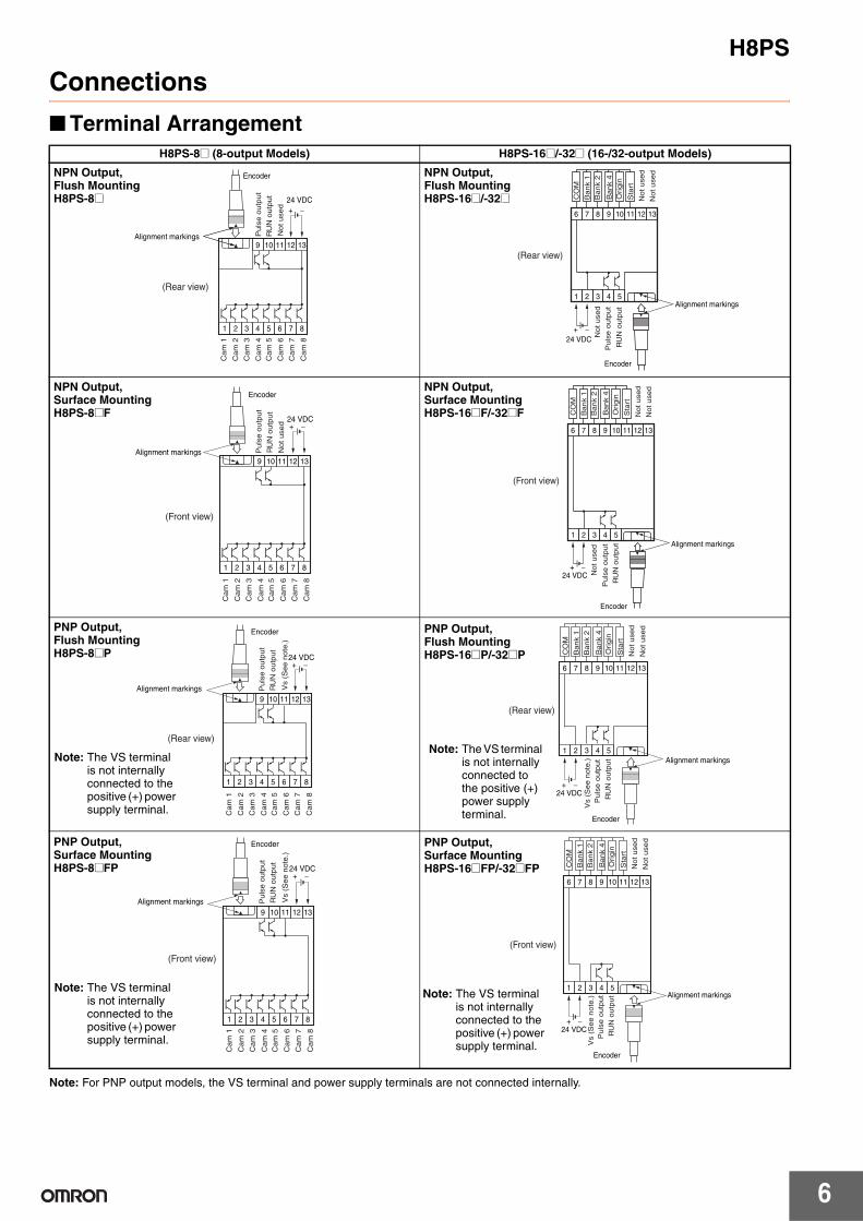
■ Terminal Arrangement
Note: For PNP output models, the VS terminal and power supply terminals are not connected internally.
H8PS-8@ (8-output Models) H8PS-16@/-32@ (16-/32-output Models)
Encoder
1 2 3 4 5 6 7 8
9 10 11 12 13
24 VDC
+ −
Alignment markings
(Rear view)
Puls
e o
utp
ut
RU
N o
utp
ut
Not used
Cam
1
Cam
2
Cam
3
Cam
4
Cam
5
Cam
6
Cam
7
Cam
8
NPN Output, Flush Mounting H8PS-8@
Encoder
6 7 8 9 10 11 12 13
1 2 3 4 5Alignment markings
(Rear view)
24 VDC
+ −
Bank 1
Bank 2
Bank 4
Ori
gin
Sta
rt
Not used
Not used
Not used
Puls
e o
utp
ut
RU
N o
utp
ut
CO
M
NPN Output, Flush MountingH8PS-16@/-32@
1 2 3 4 5 6 7 8
9 10 11 12 13
24 VDC+ −
Encoder
Alignment markings
(Front view)
Pu
lse o
utp
ut
RU
N o
utp
ut
Not u
sed
Cam
1
Cam
2
Cam
3
Cam
4
Cam
5
Cam
6
Cam
7
Cam
8
NPN Output,Surface Mounting H8PS-8@F
6 7 8 9 10 11 12 13
1 2 3 4 5
24 VDC+ −
Encoder
Alignment markings
(Front view)
Bank 1
Bank 2
Bank 4
Ori
gin
Sta
rt
Not used
Not used
Not used
Puls
e o
utp
ut
RU
N o
utp
ut
CO
M
NPN Output,Surface Mounting H8PS-16@F/-32@F
1 2 3 4 5 6 7 8
9 10 11 12 13
24 VDC+ −
Encoder
Alignment markings
(Rear view)
Puls
e o
utp
ut
RU
N o
utp
ut
Cam
1
Cam
2
Cam
3
Cam
4
Cam
5
Cam
6
Cam
7
Cam
8
Vs (
See n
ote
.)
PNP Output,Flush Mounting H8PS-8@P
Note: The VS terminal is not internally connected to the positive (+) power supply terminal.
6 7 8 9 10 11 12 13
1 2 3 4 5
24 VDC+ −
Encoder
Alignment markings
(Rear view)
Bank 1
Bank 2
Bank 4
Ori
gin
Sta
rt
Not used
Not used
Vs (
See n
ote
.)
Puls
e o
utp
ut
RU
N o
utp
ut
CO
M
PNP Output,Flush MountingH8PS-16@P/-32@P
Note: The VS terminal is not internally connected to the positive (+) power supply terminal.
1 2 3 4 5 6 7 8
9 10 11 12 13
24 VDC+ −
Encoder
Alignment markings
(Front view)
Puls
e o
utp
ut
RU
N o
utp
ut
Cam
1
Cam
2
Cam
3
Cam
4
Cam
5
Cam
6
Cam
7
Cam
8
Vs (
Se
e n
ote
.)
PNP Output,Surface Mounting H8PS-8@FP
Note: The VS terminal is not internally connected to the positive (+) power supply terminal.
6 7 8 9 10 11 12 13
1 2 3 4 5
24 VDC+ −
Encoder
Alignment markings
(Front view)
Bank 1
Bank 2
Bank 4
Ori
gin
Sta
rt
Not used
Not used
Vs (
See n
ote
.)
Puls
e o
utp
ut
RU
N o
utp
ut
CO
M
PNP Output,Surface Mounting H8PS-16@FP/-32@FP
Note: The VS terminal is not internally connected to the positive (+) power supply terminal.
H8PS
7
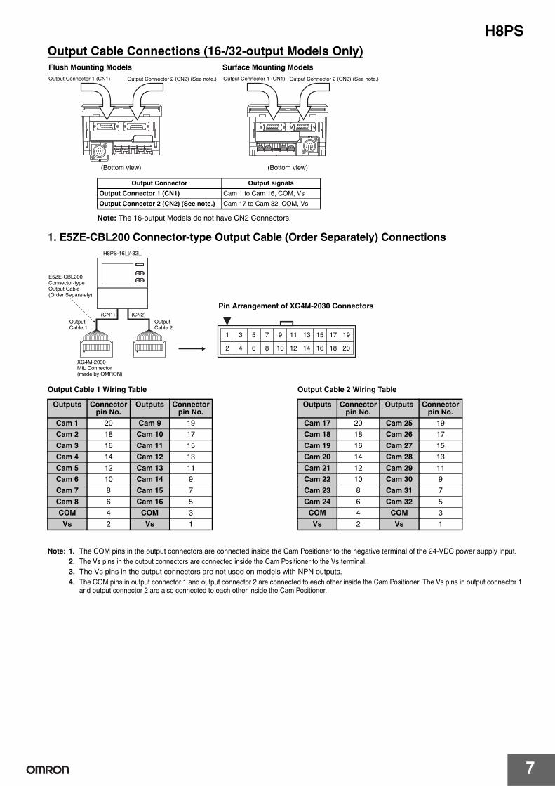
Output Cable Connections (16-/32-output Models Only)
1. E5ZE-CBL200 Connector-type Output Cable (Order Separately) Connections
Output Cable 1 Wiring Table Output Cable 2 Wiring Table
Note: 1. The COM pins in the output connectors are connected inside the Cam Positioner to the negative terminal of the 24-VDC power supply input.
2. The Vs pins in the output connectors are connected inside the Cam Positioner to the Vs terminal.
3. The Vs pins in the output connectors are not used on models with NPN outputs.
4. The COM pins in output connector 1 and output connector 2 are connected to each other inside the Cam Positioner. The Vs pins in output connector 1 and output connector 2 are also connected to each other inside the Cam Positioner.
Output Connector 1 (CN1) Output Connector 2 (CN2) (See note.)Output Connector 1 (CN1) Output Connector 2 (CN2) (See note.)
(Bottom view) (Bottom view)
Note: The 16-output Models do not have CN2 Connectors.
Output Connector Output signals
Output Connector 1 (CN1) Cam 1 to Cam 16, COM, Vs
Output Connector 2 (CN2) (See note.) Cam 17 to Cam 32, COM, Vs
Flush Mounting Models Surface Mounting Models
(CN1)
E5ZE-CBL200Connector-type Output Cable(Order Separately)
H8PS-16@/-32@
(CN2)
XG4M-2030MIL Connector (made by OMRON)
1 3 5 7 9 11 13 15 17 19
2 4 6 8 10 12 14 16 18 20
Pin Arrangement of XG4M-2030 Connectors
Output Cable 1
OutputCable 2
Outputs Connector pin No.
Outputs Connector pin No.
Cam 1 20 Cam 9 19
Cam 2 18 Cam 10 17
Cam 3 16 Cam 11 15
Cam 4 14 Cam 12 13
Cam 5 12 Cam 13 11
Cam 6 10 Cam 14 9
Cam 7 8 Cam 15 7
Cam 8 6 Cam 16 5
COM 4 COM 3
Vs 2 Vs 1
Outputs Connector pin No.
Outputs Connector pin No.
Cam 17 20 Cam 25 19
Cam 18 18 Cam 26 17
Cam 19 16 Cam 27 15
Cam 20 14 Cam 28 13
Cam 21 12 Cam 29 11
Cam 22 10 Cam 30 9
Cam 23 8 Cam 31 7
Cam 24 6 Cam 32 5
COM 4 COM 3
Vs 2 Vs 1
H8PS
8
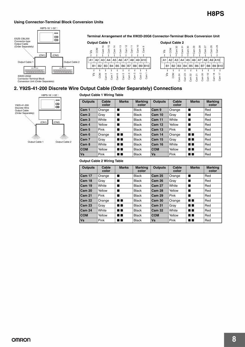
Using Connector-Terminal Block Conversion Units
2. Y92S-41-200 Discrete Wire Output Cable (Order Separately) Connections
A1 A2 A3 A4 A5 A6 A7 A8 A9 A10
B1 B2 B3 B4 B5 B6 B7 B8 B9 B10
A1 A2 A3 A4 A5 A6 A7 A8 A9 A10
B1 B2 B3 B4 B5 B6 B7 B8 B9 B10
XW2D-20G6 Connector-Terminal Block Conversion Unit (Order Separately)
H8PS-16@/-32@
(CN1)
E5ZE-CBL200Connector-type Output Cable(Order Separately)
Output Cable 1
Terminal Arrangement of the XW2D-20G6 Connector-Terminal Block Conversion Unit
Output Cable 2
Output Cable 2Output Cable 1
(CN2)
Vs
Vs
CO
M
CO
M
Ca
m 1
Ca
m 2
Ca
m 3
Ca
m 4
Ca
m 5
Ca
m 6
Ca
m 7
Ca
m 8
Ca
m 9
Ca
m 1
0
Ca
m 1
1
Ca
m 1
2
Ca
m 1
3
Ca
m 1
4
Ca
m 1
5
Ca
m 1
6
Vs
CO
M
Ca
m 1
7
Ca
m 1
8
Ca
m 1
9
Ca
m 2
0
Ca
m 2
1
Ca
m 2
2
Ca
m 2
3
Ca
m 2
4
Vs
CO
M
Ca
m 2
5
Ca
m 2
6
Ca
m 2
7
Ca
m 2
8
Ca
m 2
9
Ca
m 3
0
Ca
m 3
1
Ca
m 3
2
H8PS-16@/-32@
(CN1)
Y92S-41-200 Discrete Wire Output Cable(Order Separately)
Output Cable 2 Output Cable 1
(CN2)
Output Cable 1 Wiring Table
Output Cable 2 Wiring Table
Outputs Cable color
Marks Marking color
Outputs Cable color
Marks Marking color
Cam 1 Orange ■ Black Cam 9 Orange ■ Red
Cam 2 Gray ■ Black Cam 10 Gray ■ Red
Cam 3 White ■ Black Cam 11 White ■ Red
Cam 4 Yellow ■ Black Cam 12 Yellow ■ Red
Cam 5 Pink ■ Black Cam 13 Pink ■ Red
Cam 6 Orange ■ ■ Black Cam 14 Orange ■ ■ Red
Cam 7 Gray ■ ■ Black Cam 15 Gray ■ ■ Red
Cam 8 White ■ ■ Black Cam 16 White ■ ■ Red
COM Yellow ■ ■ Black COM Yellow ■ ■ Red
Vs Pink ■ ■ Black Vs Pink ■ ■ Red
Outputs Cable color
Marks Marking color
Outputs Cable color
Marks Marking color
Cam 17 Orange ■ Black Cam 25 Orange ■ Red
Cam 18 Gray ■ Black Cam 26 Gray ■ Red
Cam 19 White ■ Black Cam 27 White ■ Red
Cam 20 Yellow ■ Black Cam 28 Yellow ■ Red
Cam 21 Pink ■ Black Cam 29 Pink ■ Red
Cam 22 Orange ■ ■ Black Cam 30 Orange ■ ■ Red
Cam 23 Gray ■ ■ Black Cam 31 Gray ■ ■ Red
Cam 24 White ■ ■ Black Cam 32 White ■ ■ Red
COM Yellow ■ ■ Black COM Yellow ■ ■ Red
Vs Pink ■ ■ Black Vs Pink ■ ■ Red
H8PS
9
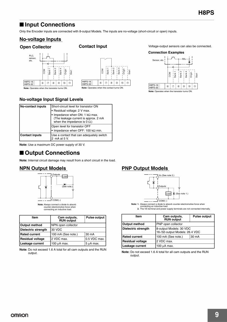
■ Input ConnectionsOnly the Encoder inputs are connected with 8-output Models. The inputs are no-voltage (short-circuit or open) inputs.
No-voltage Inputs
No-voltage Input Signal Levels
Note: Use a maximum DC power supply of 30 V.
■ Output Connections Note: Internal circuit damage may result from a short circuit in the load.
NPN Output Models
Note: Do not exceed 1.6 A total for all cam outputs and the RUN output.
PNP Output Models
Note: Do not exceed 1.6 A total for all cam outputs and the RUN output.
H8PS-16@H8PS-32@
6 7 8 9 10 11
Note: Operates when the contact turns ON.
CO
M
Ba
nk 1
Ba
nk 2
Ba
nk 4
Ori
gin
Sta
rt
Sensor, etc.
H8PS-16@H8PS-32@
6 7 8 9 10 11
Note: Operates when the transistor turns ON.
CO
M
Ba
nk 1
Ba
nk 2
Ba
nk 4
Ori
gin
Sta
rt
H8PS-16@H8PS-32@
Note: Operates when the transistor turns ON.
PLC, sensor,etc.
6 7 8 9 10 11
CO
M
Ba
nk 1
Ba
nk 2
Ba
nk 4
Ori
gin
Sta
rt
Open Collector Contact Input Voltage-output sensors can also be connected.
Connection Examples
No-contact inputs Short-circuit level for transistor ON
• Residual voltage: 2 V max.
• Impedance when ON: 1 kΩ max. (The leakage current is approx. 2 mA when the impedance is 0 Ω.)
Open level for transistor OFF
• Impedance when OFF: 100 kΩ min.
Contact inputs Use a contact that can adequately switch 2 mA at 5 V.
Item Cam outputs, RUN output
Pulse output
Output method NPN open collector
Dielectric strength 30 VDC
Rated current 100 mA (See note.) 30 mA
Residual voltage 2 VDC max. 0.5 VDC max.
Leakage current 100 µA max. 5 µA max.
Note: Always connect a diode to absorb counter-electromotive force when connecting an inductive load.
Load Outputs
COM/(−)
(See note.)
Item Cam outputs, RUN output
Pulse output
Output method PNP open collector
Dielectric strength 8-output Models: 30 VDC 16-/32-output Models: 26.4 VDC
Rated current 100 mA (See note.) 30 mA
Residual voltage 2 VDC max.
Leakage current 100 µA max.
Vs (See note 2.)
Load
Outputs
COM/(−)
(See note 1.)
Note: 1. Always connect a diode to absorb counter-electromotive force when connecting an inductive load.
2. The VS terminal and power supply terminals are not connected internally.
H8PS
10
Operating Mode
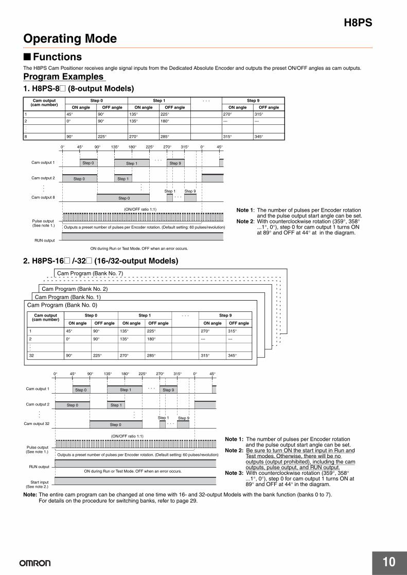
■ FunctionsThe H8PS Cam Positioner receives angle signal inputs from the Dedicated Absolute Encoder and outputs the preset ON/OFF angles as cam outputs.
Program Examples
1. H8PS-8@ (8-output Models)
2. H8PS-16@ /-32@ (16-/32-output Models)
Note: The entire cam program can be changed at one time with 16- and 32-output Models with the bank function (banks 0 to 7).For details on the procedure for switching banks, refer to page 29.
Cam output (cam number)
Step 0 Step 1 Step 9
ON angle OFF angle ON angle OFF angle ON angle OFF angle
1 45° 90° 135° 225° 270° 315°
2 0° 90° 135° 180° --- ---
8 90° 225° 270° 285° 315° 345°
Cam output 1
Cam output 2
Cam output 8
Pulse output (See note 1.)
RUN output
Note 1: The number of pulses per Encoder rotation and the pulse output start angle can be set.
Note 2: With counterclockwise rotation (359°, 358° ...1°, 0°), step 0 for cam output 1 turns ON at 89° and OFF at 44° at in the diagram.
0° 45° 90° 135° 180° 225° 270° 315° 0° 45°
Step 1 Step 9
Step 0
Step 0
Outputs a preset number of pulses per Encoder rotation. (Default setting: 60 pulses/revolution)
(ON/OFF ratio 1:1)
ON during Run or Test Mode. OFF when an error occurs.
Step 1
Step 1 Step 9Step 0
Cam output 1
Cam output 2
Cam output 32
Pulse output (See note 1.)
RUN output
Start input (See note 2.)
Note 1: The number of pulses per Encoder rotation and the pulse output start angle can be set.
Note 2: Be sure to turn ON the start input in Run and Test modes. Otherwise, there will be no outputs (output prohibited), including the cam outputs, pulse output, and RUN output.
Note 3: With counterclockwise rotation (359°, 358° ...1°, 0°), step 0 for cam output 1 turns ON at 89° and OFF at 44° in the diagram.
0° 45° 90° 135° 180° 225° 270° 315° 0° 45°
Step 0
Step 0
Outputs a preset number of pulses per Encoder rotation. (Default setting: 60 pulses/revolution)
(ON/OFF ratio 1:1)
ON during Run or Test Mode. OFF when an error occurs.
Step 1
Step 1 Step 9Step 0
Step 1 Step 9
Cam Program (Bank No. 7)
Cam Program (Bank No. 2)
Cam Program (Bank No. 1)
Cam Program (Bank No. 0)
Cam output (cam number)
Step 0 Step 1 Step 9
ON angle OFF angle ON angle OFF angle ON angle OFF angle
1 45° 90° 135° 225° 270° 315°
2 0° 90° 135° 180° --- ---
32 90° 225° 270° 285° 315° 345°
H8PS
11
Nomenclature
■ Displays
■ Operation Keys
8-output Models
16-/32-output Models
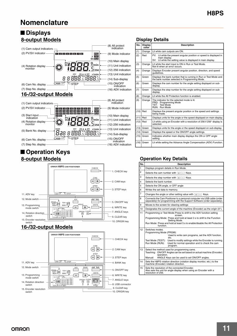
Display DetailsNo. Display
colorDescription
(1) Orange Lit while cam outputs are ON.
(2) Red PV: Lit while the present angular position or speed is displayed in main display.
SV: Lit while the setting value is displayed in main display.
(3) Orange Lit while the start input is ON in Run or Test Mode. Not lit when an error occurs.
(4) Orange Displays Encoder present angular position, direction, and speed guidelines.
(5) Green Displays the bank number that is running in Run or Test Mode and the bank number selected in Programming Mode.
(6) Green Displays the cam number for the angle setting displayed on sub-display.
(7) Green Displays the step number for the angle setting displayed on sub-display.
(8) Orange Lit while the All Protection function is enabled.
(9) Orange The indicator for the selected mode is lit. PRG: Programming Mode TST: Test ModeRUN: Run Mode
(10) Red Displays the present angular position or the speed and settings being made.
(11) Red Displays units for the angle or the speed displayed on main display.
(12) Red Lit while using an Encoder with a resolution of 256 if 256° display is selected.
(13) Green Displays units for the angle or the speed displayed on sub-display.
(14) Green Displays the speed or the ON/OFF angle settings.
(15) Green Indicates whether main display displays the ON or OFF angle setting.
(16) Green Lit while setting the Advance Angle Compensation (ADV) Function.
CAM STEP
(1) Cam output indicators
(2) PV/SV indicator
(4) Rotation display monitor
(6) Cam No. display
(7) Step No. display
(8) All protect indication
(9) Mode indicator
(10) Main display
(11) Unit indication
(13) Unit indication
(12) 256 indication
(14) Sub-display
(15) ON/OFF indication
(16) ADV indication
1 2 3 4 5 6 7 8 PRG
TST
RUN
CAM STEP
(8) All protect indication
(9) Mode indicator
(10) Main display
(11) Unit indication
(13) Unit indication
(12) 256 indication
(14) Sub-display
(15) ON/OFF indication (16) ADV indication
1 2 3 4 5 6 7 8 9 10 PRG
TST
RUN
11 12 13 14 15 16 17 18 19 2021 22 23 24 25 26 27 28 29 3031 32(3) Start input
indication
(5) Bank No. display
(2) PV/SV indicator
(4) Rotation display monitor
(6) Cam No. display
(7) Step No. display
(1) Cam output indicators
8-output Models
16-/32-output Models
Operation Key DetailsNo. Description
1 Displays program details in Run Mode.
2 Selects the cam number with Keys.
3 Selects the step number with Keys.
4 Selects the bank number.
5 Selects the ON angle, or OFF angle
6 Writes the set data to memory.
7 Changes the angle or other setting value with Keys.
8 Connects the Cam Positioner to a personal computer via USB cable (order separately) for programming with the Support Software (order separately).
9 Moves to the screen for clearing settings
10 Designates the current angle of the machine (Encoder) as the origin (0°).
11 Programming or Test Mode:Press to shift to the ADV function setting screen.
Programming Mode: Press and hold at least 3 s to shift to the Function Setting Mode.
Run Mode: Press and hold at least 5 s to enable/disable the All Protection function.
12 Switches modes.Programming Mode (PRGM): Used to write cam programs, set the ADV function,
etc.Test Mode (TEST): Used to modify settings while the Encoder is running.Run Mode (RUN): Used for normal operation and to check the cam
program.
13 Select the method used for programming cams.Teaching: ON/OFF Angles can be set based on actual machine (Encoder)
operation.Manual: ANGLE Keys can be used to set ON/OFF angles.
14 Sets the H8PS rotation direction (rotation display monitor, etc.) to the machine (Encoder) rotation direction.
15 Sets the resolution of the connected Encoder. Also sets the unit for angle display when using an Encoder with a resolution of 256.
ORIGIN
CHECK
CAM
STEP
CLEAR
ANGLE
ADV
WRITE
DO NOT USE.
CW
CCW
PLS/RANGDSPL
CAM STEP
1. CHECK key
2. CAM keys
3. STEP keys
5. ON/OFF key
6. WRITE key
7. ANGLE keys
9. CLEAR key
10. ORIGIN key
13. Programming mode switch
15. Encoder resolution switch
12. Mode switchPRGMTESTRUN
TCH
MAN
ON OFF
OFF
ON
4321
OFF
OFF
ON
ON
OFF
ON
OFF
720 360360360360256256256ON
43
11. ADV key
14. Rotation direction switch
1. CHECK key
2. CAM keys
3. STEP keys
5. ON/OFF key
6. WRITE key
7. ANGLE keys
9. CLEAR key
10. ORIGIN key
8. USB connector
4. BANK key
ON OFF
OFF
ON
4321
OFF
OFF
ON
ON
OFF
ON
OFF
720 360360360360256256256ON
43
ORIGIN
CHECK
CAM
STEP
CLEAR
ANGLE
ADV
WRITE
DO NOT USE.
CW
CCW
PLS/RANGDSPL
CAM STEP
PRGMTESTRUN
TCH
MAN
BANK
13. Programming mode switch
15. Encoder resolution switch
12. Mode switch
14. Rotation direction switch
11. ADV key
H8PS
12
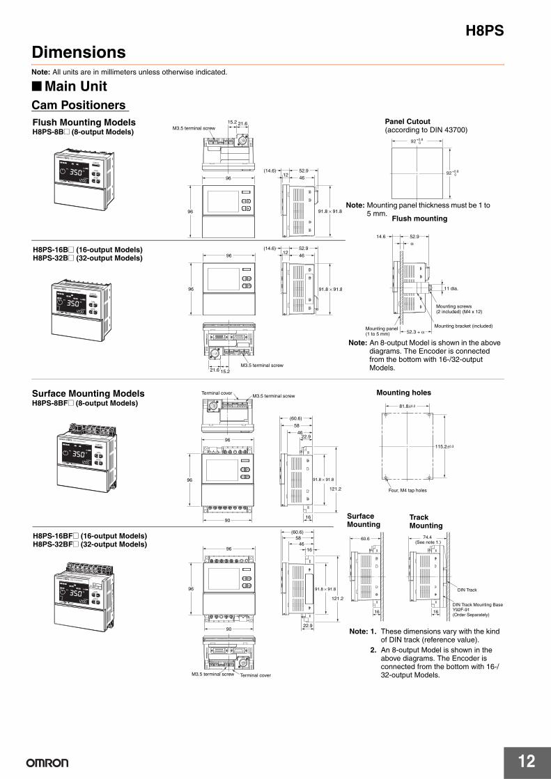
DimensionsNote: All units are in millimeters unless otherwise indicated.
■ Main Unit
Cam Positioners
52.9
46
(14.6)12
91.8 × 91.8
15.2
M3.5 terminal screw
96
96
21.6
52.9
46
(14.6)12
91.8 × 91.8
15.2
M3.5 terminal screw
96
96
21.6
14.6
Mounting panel(1 to 5 mm)
α
52.9
52.3 + α
11 dia.
Mounting bracket (included)
Mounting screws (2 included) (M4 x 12)
92+0.80
92+0.80
Flush Mounting Models H8PS-8B@ (8-output Models)
Panel Cutout (according to DIN 43700)
Note: Mounting panel thickness must be 1 to 5 mm.
Flush mounting
Note: An 8-output Model is shown in the above diagrams. The Encoder is connected from the bottom with 16-/32-output Models.
H8PS-16B@ (16-output Models)H8PS-32B@ (32-output Models)
115.2±0.3
Four, M4 tap holes
81.8±0.2
74.4 (See note 1.)
60.6
DIN Track
DIN Track Mounting BaseY92F-91(Order Separately)
16 16
(60.6)
58
4622.9
16
91.8 × 91.8
M3.5 terminal screw
96
96
90
121.2
Terminal cover
M3.5 terminal screw
96
96
90
(60.6)
58
46
16
121.2
22.9
91.8 × 91.8
Terminal cover
Mounting holes
Surface Mounting
Note: 1. These dimensions vary with the kind of DIN track (reference value).
2. An 8-output Model is shown in the above diagrams. The Encoder is connected from the bottom with 16-/32-output Models.
H8PS-16BF@ (16-output Models)H8PS-32BF@ (32-output Models)
Track Mounting
Surface Mounting Models H8PS-8BF@ (8-output Models)
H8PS
13
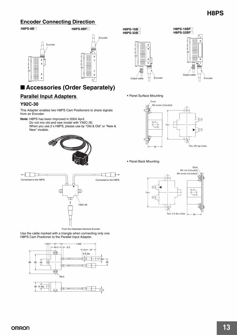
Encoder Connecting Direction
■ Accessories (Order Separately)
Parallel Input Adapters
Y92C-30
This Adapter enables two H8PS Cam Positioners to share signals from an Encoder.
Note: H8PS has been improved in 2004 April.Do not mix old and new model with Y92C-30.When you use 2 x H8PS, please use by "Old & Old" or "New & New" models.
Use the cable marked with a triangle when connecting only one H8PS Cam Positioner to the Parallel Input Adapter.
• Panel Surface Mounting
• Panel Back Mounting
Encoder
Output cable Encoder
Encoder
Output cable
Encoder
H8PS-8B@ H8PS-8BF@ H8PS-16B@H8PS-32B@
H8PS-16BF@H8PS-32BF@
Connected to the H8PS. Connected to the H8PS.
Y92C-30
From the Dedicated Absolute Encoder
R6.5
14 dia.36
40.4 6.5
246089
47 1,030
15 37
8.5 dia.
17 dia.
26
11.3
9
74±1
Two, M4 tap holes
Front
M4 screw (included)
36
74±1
Two, 4.3 dia. holes
Back
M4 screw (included)
M4 nut (included)
36
H8PS
14
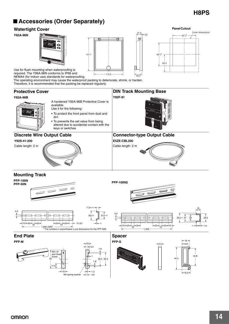
■ Accessories (Order Separately)
CHECK
CAMSTEP
CAM
STEP
Y92A-96NY92A-96N
92 +0.8 0
92 +0.8 0 131.7
21.9 (2)
115.6 28.9
69.3
Cover dimensions
CAM
STEP
CHECK
CAMSTEP
Watertight Cover
Y92A-96N
Use for flush mounting when waterproofing is required. The Y96A-96N conforms to IP66 and NEMA4 (for indoor use) standards for waterproofing.The operating environment may cause the waterproof packing to deteriorate, shrink, or harden. Therefore, it is recommended that the packing be replaced regularly.
Panel Cutout
Protective Cover
Y92A-96B
A hardened Y92A-96B Protective Cover is available.Use it for the following:
• To protect the front panel from dust and dirt.
• To prevents the set value from being altered due to accidental contact with the keys or switches.
DIN Track Mounting Base
Y92F-91
Discrete Wire Output Cable
Y92S-41-200
Cable length: 2 m
Connector-type Output Cable
E5ZE-CBL200
Cable length: 2 m
1
35±0.3
7.3±0.15
27±0.15
4.5
15 25 2510
15 (5)*10
25 25
* The numbers in parentheses () are dimensions for the PFP-50N. 1,000 (500)*
15 25 25
1,000
4.5
25 25 1510
1
242735±0.3
16
1.5
29.2
10
4.8
1.3
35.5 35.3
1.8
1
1.8
10
6.2
M4 spring washer
50
11.5
M4 x 8 pan-head screw
10
5
16
12
44.334.8
16.5
Mounting Track
PFP-100NPFP-50N
PFP-100N2
End Plate
PFP-M
Spacer
PFP-S
H8PS
15
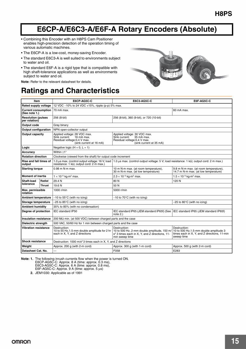
• Combining this Encoder with an H8PS Cam Positioner enables high-precision detection of the operation timing of various automatic machines.
• The E6CP-A is a low-cost, money-saving Encoder.
• The standard E6C3-A is well suited to environments subject to water and oil.
• The standard E6F-A is a rigid type that is compatible with high shaft-tolerance applications as well as environments subject to water and oil.
Note: Refer to the relevant datasheet for details.
Ratings and Characteristics
Note: 1. The following inrush currents flow when the power is turned ON.E6CP-AG5C-C: Approx. 8 A (time: approx. 0.3 ms), E6C3-AG5C-C: Approx. 6 A (time: approx. 0.8 ms), E6F-AG5C-C: Approx. 9 A (time: approx. 5 µs)
2. JEM1030: Applicable as of 1991
E6CP-A/E6C3-A/E6F-A Rotary Encoders (Absolute)
Item E6CP-AG5C-C E6C3-AG5C-C E6F-AG5C-C
Rated supply voltage 12 VDC −10% to 24 VDC +15%, ripple (p-p) 5% max.
Current consumption (See note 1.)
70 mA max. 60 mA max.
Resolution (pulses per rotation)
256 (8-bit) 256 (8-bit), 360 (9-bit), or 720 (10-bit)
Output code Gray binary
Output configuration NPN open-collector output
Output capacity Applied voltage: 28 VDC max. Sink current: 16 mA max. Residual voltage:0.4 V max.
(sink current at 16 mA)
Applied voltage: 30 VDC max.Sink current: 35 mA max.Residual voltage:0.4 V max.
(sink current at 35 mA)
Logic Negative logic (H = 0, L = 1)
Accuracy Within ±1°
Rotation direction Clockwise (viewed from the shaft) for output code increment
Rise and fall times of output
1.0 µs max. (control output voltage: 16 V; load resistance: 1 kΩ; output cord: 2 m max.)
1.0 µs max. (control output voltage: 5 V; load resistance: 1 kΩ; output cord: 2 m max.)
Starting torque 0.98 m N·m max. 10 m N·m max. (at room temperature), 30 m N·m max. (at low temperature)
9.8 m N·m max. (at room temperature), 14.7 m N·m max. (at low temperature)
Moment of inertia 1 × 10⁻⁶ kg·m2 max. 2.3 × 10⁻⁶ kg·m2 max. 1.5 × 10⁻⁶ kg·m2 max.
Shaft-load tolerance
Radial 29.4 N 80 N 120 N
Thrust 19.6 N 50 N
Max. permissible rotation
1000 r/min 5000 r/min
Ambient temperature −10 to 55°C (with no icing) −10 to 70°C (with no icing)
Storage temperature −25 to 85°C (with no icing) −25 to 80°C (with no icing)
Ambient humidity 35% to 85% (with no condensation)
Degree of protection IEC standard IP50 IEC standard IP65 (JEM standard IP65f) (See note 2.)
IEC standard IP65 (JEM standard IP65f)
Insulation resistance 200 MΩ min. (at 500 VDC) between charged parts and the case
Dielectric strength 500 VAC, 50/60 Hz for 1 min between charged parts and the case
Vibration resistance Destruction: 10 to 55 Hz,1.5-mm double amplitude for 2 hr each in X, Y, and Z directions
Destruction: 10 to 500 Hz, 2-mm double amplitude, 150 m/s2 3 times each in X, Y, and Z directions, 11-min sweep time
Destruction: 10 to 500 Hz,1.5-mm double amplitude 3 times each in X, Y, and Z directions, 11-min sweep time
Shock resistance Destruction: 1000 m/s2 3 times each in X, Y, and Z directions
Weight Approx. 200 g (with 2-m cord) Approx. 300 g (with 1-m cord) Approx. 500 g (with 2-m cord)
Datasheet Cat. No. --- F058 E283
H8PS
16
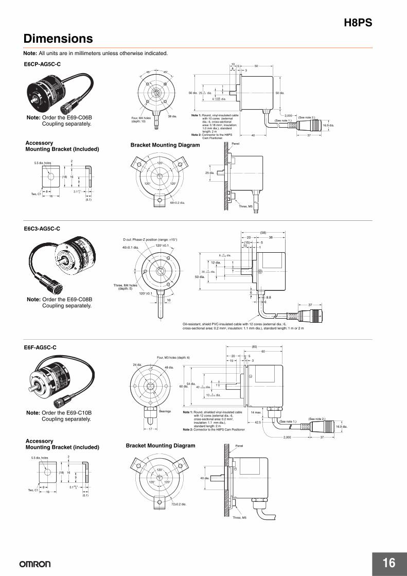
DimensionsNote: All units are in millimeters unless otherwise indicated.
45° 45°
38 dia.
56 dia. 50 dia.
16.9 dia.
2,000
1050
40 37
5
38
1
Four, M4 holes (depth: 10) (See note 1.)
(See note 2.)Note 1: Round, vinyl-insulated cable
with 10 cores (external dia.: 6, cross-sectional area: 0.18 mm2, insulation: 1.0 mm dia.), standard length: 2 m
Note 2: Connector to the H8PS Cam Positioner.
25 dia.0−0.2
6 dia.−0.008−0.020
8
16
5.5 dia. holes
Two, C1
(18) 16
9
2
(5.1)
3.1+0.10
120°
120° 120°
25 dia.
Three, M5
Panel
68±0.2 dia.
E6CP-AG5C-C
Accessory Mounting Bracket (Included)
Bracket Mounting Diagram
Note: Order the E69-C06B Coupling separately.
30 dia.
Oil-resistant, shield PVC-insulated cable with 12 cores (external dia.: 6,
cross-sectional area: 0.2 mm2, insulation: 1.1 mm dia.), standard length: 1 m or 2 m
50 dia.
D cut: Phase-Z position (range: ±15°)
40±0.1 dia.
10
Three, M4 holes (depth: 5)
120°±0.1
120°±0.1
8 dia.+0
−0.018
+0−0.021
6
8.8
6
12 dia. 1
1
510(15)
3820
(58)
37
E6C3-AG5C-C
Note: Order the E69-C08B Coupling separately.
8
16
5.5 dia. holes
Two, C1
(18) 16
9
2
3.1+0.10
(5.1)
120°
120°
120°
72±0.2 dia.
Panel
Three, M5
40 dia.
Bearings
48 dia.24 dia.
Four, M3 holes (depth: 6)
17
160 dia.54 dia.
15 33
20
60
(85)
5
14 max.
42.5(See note 2.)
(See note 1.)
2,000
16.9 dia.
37
Note 1: Round, shielded vinyl-insulated cable with 12 cores (external dia.: 6,
cross-sectional area: 0.2 mm2, insulation: 1.1 mm dia.), standard length: 2 m Note 2: Connector to the H8PS Cam Positioner
10 dia.0−0.015
40 dia.0−0.025
E6F-AG5C-C
Bracket Mounting Diagram Accessory Mounting Bracket (included)
Note: Order the E69-C10B Coupling separately.
H8PS
17
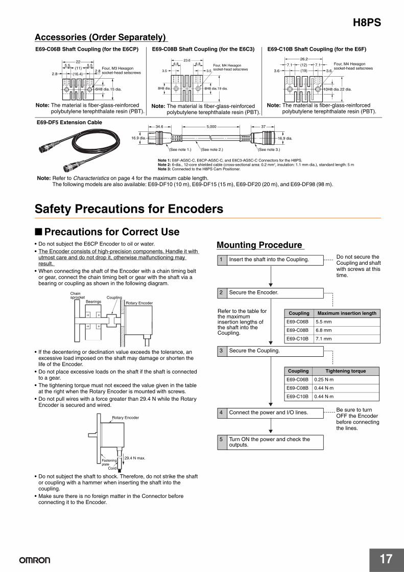
Accessories (Order Separately)
Safety Precautions for Encoders
■ Precautions for Correct Use • Do not subject the E6CP Encoder to oil or water.
• The Encoder consists of high-precision components. Handle it with utmost care and do not drop it, otherwise malfunctioning may result.
• When connecting the shaft of the Encoder with a chain timing belt or gear, connect the chain timing belt or gear with the shaft via a bearing or coupling as shown in the following diagram.
• If the decentering or declination value exceeds the tolerance, an excessive load imposed on the shaft may damage or shorten the life of the Encoder.
• Do not place excessive loads on the shaft if the shaft is connected to a gear.
• The tightening torque must not exceed the value given in the table at the right when the Rotary Encoder is mounted with screws.
• Do not pull wires with a force greater than 29.4 N while the Rotary Encoder is secured and wired.
• Do not subject the shaft to shock. Therefore, do not strike the shaft or coupling with a hammer when inserting the shaft into the coupling.
• Make sure there is no foreign matter in the Connector before connecting it to the Encoder.
Mounting Procedure
22
Four, M3 Hexagon socket-head setscrews
6H8 dia.15 dia.
(11)
(16.4)2.8
2.8
5.5 5.5
26.2
Four, M4 Hexagon socket-head setscrews
10H8 dia.22 dia.
(12)
(19)3.6 3.6
7.17.1
16.9 dia. 16.9 dia.
34.6
(See note 1.) (See note 3.)(See note 2.)
375,000
Note 1: E6F-AG5C-C, E6CP-AG5C-C, and E6C3-AG5C-C Connectors for the H8PS. Note 2: 6-dia., 12-core shielded cable (cross-sectional area: 0.2 mm2, insulation: 1.1 mm dia.), standard length: 5 m Note 3: Connected to the H8PS Cam Positioner.
8H8 dia. 8H8 dia.19 dia.
3.5 3.5
6.8 6.823.6
Four, M4 Hexagon socket-head setscrews
E69-C06B Shaft Coupling (for the E6CP)
Note: The material is fiber-glass-reinforced polybutylene terephthalate resin (PBT).
E69-C10B Shaft Coupling (for the E6F)
Note: The material is fiber-glass-reinforced polybutylene terephthalate resin (PBT).
Note: Refer to Characteristics on page 4 for the maximum cable length. The following models are also available: E69-DF10 (10 m), E69-DF15 (15 m), E69-DF20 (20 m), and E69-DF98 (98 m).
E69-DF5 Extension Cable
E69-C08B Shaft Coupling (for the E6C3)
Note: The material is fiber-glass-reinforced polybutylene terephthalate resin (PBT).
Chain sprocket
Bearings Coupling
Rotary Encoder
Rotary Encoder
Fastening plate
Cord
29.4 N max.
Refer to the table for the maximum insertion lengths of the shaft into the Coupling.
1 Insert the shaft into the Coupling.
2 Secure the Encoder.
3 Secure the Coupling.
4 Connect the power and I/O lines.
5 Turn ON the power and check the outputs.
Coupling Maximum insertion length
E69-C06B 5.5 mm
E69-C08B 6.8 mm
E69-C10B 7.1 mm
Coupling Tightening torque
E69-C06B 0.25 N·m
E69-C08B 0.44 N·m
E69-C10B 0.44 N·m
Do not secure the Coupling and shaft with screws at this time.
Be sure to turn OFF the Encoder before connecting the lines.

H8PS
18
Safety Precautions for Cam Positioners
Refer to Safety Precautions for All Counters.
■ Precautions for Safe Use Observe the following items to ensure the safe use of this product.
Environmental Precautions • Store the H8PS within specified ratings. If the H8PS has been
stored at temperatures −10°C or lower, let it stand for 3 hours or longer at room temperature before turning ON the power supply.
• Use the H8PS within the specified ratings for operating temperature and humidity.
• Do not operate the H8PS in locations subject to sudden or extreme changes in temperature, or locations where high humidity may result in condensation.
• Do not use the H8PS in locations subject to vibrations or shock. Extended use in such locations may result in damage due to stress.
• Do not use the H8PS in locations subject to excessive dust, corrosive gas, or direct sunlight.
• Install the H8PS well away from any sources of static electricity, such as pipes transporting molding materials, powders, or liquids.
• The H8PS is not waterproof or oil resistant. Do not use it in locations subject to water or oil.
• The life expectancy of internal components may be reduced if the H8PS is mounted side-by-side.
• Do not use organic solvents (such as paint thinner or benzine), strong alkaline, or strong acids because they will damage the external finish.
Usage Precautions • Install a switch or circuit breaker that allows the operator to
immediately turn OFF the power, and label it to clearly indicate its function.
• Pay careful attention to polarity to avoid wrong connections when wiring terminals.
• Do not connect more than two crimp terminals to the same terminal.
• Use the specified wires for wiring.Applicable Wires
AWG24 to AWG18 (cross-sectional area of 0.208 to 0.832 mm2)Solid or twisted wires of copper
• Do not connect loads that exceed the rated output current. The output elements may be destroyed, possibly resulting in short-circuit or open-circuit faults.
• Always connect a diode to protect against counterelectromotive force when using an inductive load. Counterelectromotive force may destroy output elements, possibly resulting in short-circuit or open-circuit faults.
• Use the specified cables to connect outputs.
• Do not install input lines in the same duct or conduit as power supply or other high-voltage lines. Doing so may result in malfunction due to noise. Separate the input lines from high-voltage lines.
• Internal elements may be destroyed if a voltage outside the rated voltage is applied.
• Maintain voltage fluctuations in the power supply within the specified range.
• Use a switch, relay, or other contact so that the rated power supply voltage will be reached within 0.1 s. If the power supply voltage is not reached quickly enough, the H8PS may malfunction or outputs may be unstable.
• Do not turn OFF the power supply when changing or deleting settings. The contents of the EEPROM may be corrupted.
Tighten terminal screws to a torque of 0.80 N·m so that they do not become loose.Minor fires or malfunction may occasionally occur.
For 16- and 32-output Models, leave the protective label attached to the H8PS when wiring. Removing the label before wiring may occasionally result in fire if foreign matter enters the Unit. Remove the label after the completion of wiring to ensure proper heat dissipation. Leaving the label attached may occasionally result in fire.
Do not disassemble, modify, or repair the H8PS or touch any of the internal parts. Otherwise, minor electric shock, fire, or malfunction may occasionally occur.
Do no allow metal fragments, lead wire scraps, or chips from processing during installation to fall inside the H8PS. Otherwise, minor electric shock, fire, or malfunction may occasionally occur.
Do not touch the terminals when power is being supplied.For Surface-mounting H8PS, always connect the terminal cover for after completing wiring. Otherwise, minor injury due to electric shock may occasionally occur.
!CAUTION
H8PS
19
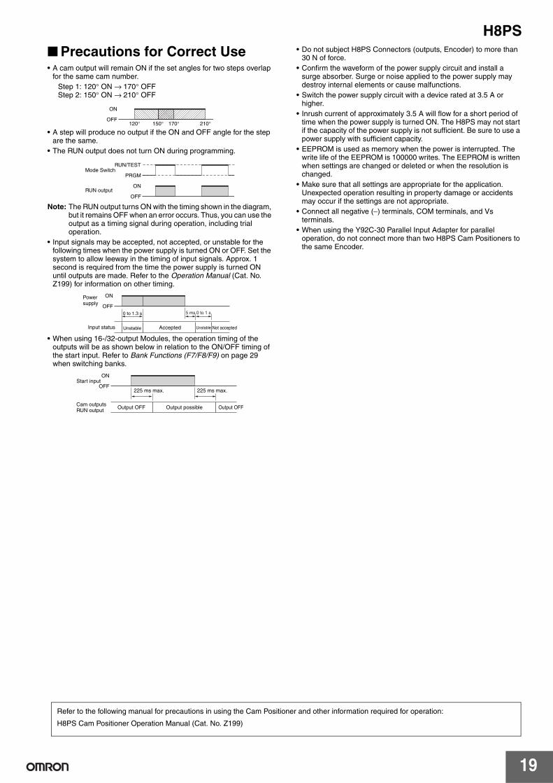
■ Precautions for Correct Use • A cam output will remain ON if the set angles for two steps overlap
for the same cam number.
Step 1: 120° ON → 170° OFF Step 2: 150° ON → 210° OFF
• A step will produce no output if the ON and OFF angle for the step are the same.
• The RUN output does not turn ON during programming.
Note: The RUN output turns ON with the timing shown in the diagram, but it remains OFF when an error occurs. Thus, you can use the output as a timing signal during operation, including trial operation.
• Input signals may be accepted, not accepted, or unstable for the following times when the power supply is turned ON or OFF. Set the system to allow leeway in the timing of input signals. Approx. 1 second is required from the time the power supply is turned ON until outputs are made. Refer to the Operation Manual (Cat. No. Z199) for information on other timing.
• When using 16-/32-output Modules, the operation timing of the outputs will be as shown below in relation to the ON/OFF timing of the start input. Refer to Bank Functions (F7/F8/F9) on page 29 when switching banks.
• Do not subject H8PS Connectors (outputs, Encoder) to more than 30 N of force.
• Confirm the waveform of the power supply circuit and install a surge absorber. Surge or noise applied to the power supply may destroy internal elements or cause malfunctions.
• Switch the power supply circuit with a device rated at 3.5 A or higher.
• Inrush current of approximately 3.5 A will flow for a short period of time when the power supply is turned ON. The H8PS may not start if the capacity of the power supply is not sufficient. Be sure to use a power supply with sufficient capacity.
• EEPROM is used as memory when the power is interrupted. The write life of the EEPROM is 100000 writes. The EEPROM is written when settings are changed or deleted or when the resolution is changed.
• Make sure that all settings are appropriate for the application. Unexpected operation resulting in property damage or accidents may occur if the settings are not appropriate.
• Connect all negative (−) terminals, COM terminals, and Vs terminals.
• When using the Y92C-30 Parallel Input Adapter for parallel operation, do not connect more than two H8PS Cam Positioners to the same Encoder.
ON
OFF120° 150° 170° 210°
ON
OFF
RUN/TEST
PRGM
RUN output
Mode Switch
Unstable Unstable Not acceptedAcceptedInput status
Power supply
0 to 1.3 s
ON
OFF5 ms 0 to 1 s
225 ms max. 225 ms max.
Output OFF Output OFFOutput possible
ON
OFF
Cam outputsRUN output
Start input
Refer to the following manual for precautions in using the Cam Positioner and other information required for operation:
H8PS Cam Positioner Operation Manual (Cat. No. Z199)
H8PS
20
Operating Procedures
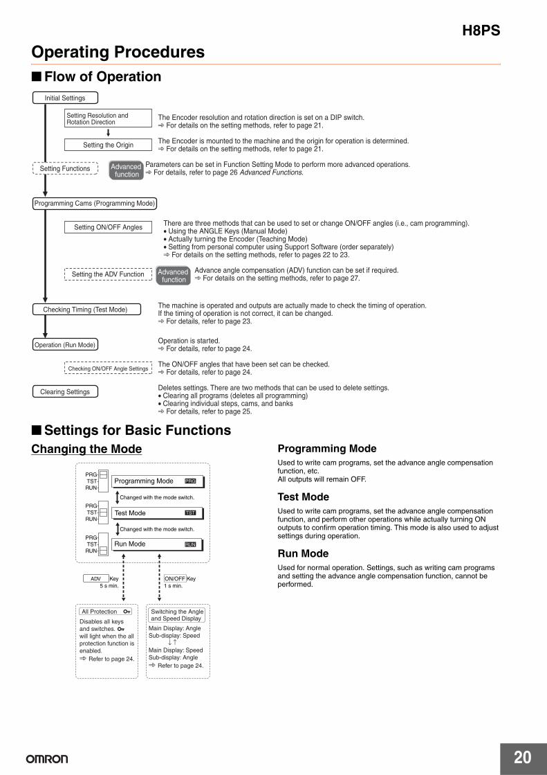
■ Flow of Operation
■ Settings for Basic Functions
Changing the Mode Programming Mode
Used to write cam programs, set the advance angle compensation function, etc. All outputs will remain OFF.
Test Mode
Used to write cam programs, set the advance angle compensation function, and perform other operations while actually turning ON outputs to confirm operation timing. This mode is also used to adjust settings during operation.
Run Mode
Used for normal operation. Settings, such as writing cam programs and setting the advance angle compensation function, cannot be performed.
The Encoder resolution and rotation direction is set on a DIP switch. ➾ For details on the setting methods, refer to page 21.
The Encoder is mounted to the machine and the origin for operation is determined. ➾ For details on the setting methods, refer to page 21.
Parameters can be set in Function Setting Mode to perform more advanced operations. ➾ For details, refer to page 26 Advanced Functions.
The machine is operated and outputs are actually made to check the timing of operation. If the timing of operation is not correct, it can be changed. ➾ For details, refer to page 23.
The ON/OFF angles that have been set can be checked. ➾ For details, refer to page 24.
Deletes settings. There are two methods that can be used to delete settings. • Clearing all programs (deletes all programming)• Clearing individual steps, cams, and banks ➾ For details, refer to page 25.
There are three methods that can be used to set or change ON/OFF angles (i.e., cam programming). • Using the ANGLE Keys (Manual Mode)• Actually turning the Encoder (Teaching Mode)• Setting from personal computer using Support Software (order separately)➾ For details on the setting methods, refer to pages 22 to 23.
Advanced function
Advance angle compensation (ADV) function can be set if required. ➾ For details on the setting methods, refer to page 27.
Operation is started. ➾ For details, refer to page 24.
Advanced function
Setting the Origin
Setting ON/OFF Angles
Setting the ADV Function
Checking ON/OFF Angle Settings
Initial Settings
Programming Cams (Programming Mode)
Checking Timing (Test Mode)
Operation (Run Mode)
Clearing Settings
Setting Functions
Setting Resolution and Rotation Direction
PRG
TST
RUN
PRG
TST
RUN
PRG
TST
RUN
All Protection Switching the Angle and Speed Display
Disables all keys
and switches.
will light when the all
protection function is
enabled.
➾ Refer to page 24.
Main Display: Angle
Sub-display: Speed
↓ ↑Main Display: Speed
Sub-display: Angle
➾ Refer to page 24.
Test Mode
Run Mode
PRG
RUN
TST
Changed with the mode switch.
Changed with the mode switch.
Key
1 s min.
ADV Key
5 s min.
ON/OFF
Programming Mode
H8PS
21
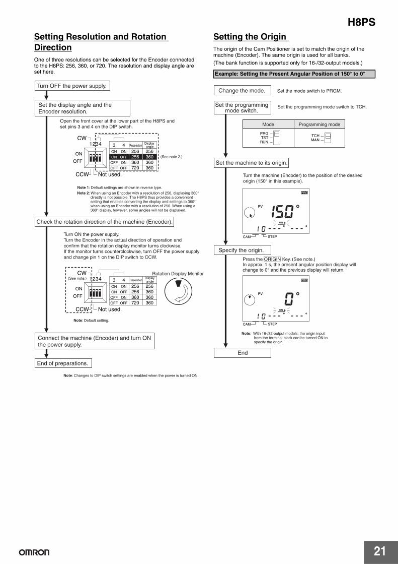
Setting Resolution and Rotation
Direction
One of three resolutions can be selected for the Encoder connected to the H8PS: 256, 360, or 720. The resolution and display angle are set here.
Setting the Origin
The origin of the Cam Positioner is set to match the origin of the machine (Encoder). The same origin is used for all banks.
(The bank function is supported only for 16-/32-output models.)
Turn OFF the power supply.
Set the display angle and the Encoder resolution.
Check the rotation direction of the machine (Encoder).
Connect the machine (Encoder) and turn ON the power supply.
End of preparations.
Open the front cover at the lower part of the H8PS and
set pins 3 and 4 on the DIP switch.
Note: Changes to DIP switch settings are enabled when the power is turned ON.
Note: Default setting.
Turn ON the power supply.
Turn the Encoder in the actual direction of operation and
confirm that the rotation display monitor turns clockwise.
If the monitor turns counterclockwise, turn OFF the power supply
and change pin 1 on the DIP switch to CCW.
Rotation Display Monitor (See note.)
Note 1: Default settings are shown in reverse type.
Note 2: When using an Encoder with a resolution of 256, displaying 360° directly is not possible. The H8PS thus provides a convenient setting that enables converting the display and settings to 360° when using an Encoder with a resolution of 256. When using a 360° display, however, some angles will not be displayed.
(See note 2.)
OFF
ON
4321
Not used. CCW
OFF
OFF
ON
ON
OFF
ON
OFF
720 360360360360256256256ON
43
CW
OFF
ON
4321
Not used. CCW
OFF
OFF
ON
ON
OFF
ON
OFF
720 360360360360256256256ON
43Display angleResolution
CW
Display angleResolution
Example: Setting the Present Angular Position of 150° to 0°
Change the mode.
Set the programming mode switch.
Set the machine to its origin.
Specify the origin.
End
Turn the machine (Encoder) to the position of the desired
origin (150° in this example).
Press the ORIGIN Key. (See note.)In approx. 1 s, the present angular position display will change to 0° and the previous display will return.
Set the mode switch to PRGM.
Set the programming mode switch to TCH.
Mode Programming mode
PRGTSTRUN
TCHMAN
CAM STEP
PRG
CAM STEP
PRG
Note: With 16-/32-output models, the origin input from the terminal block can be turned ON to specify the origin.
H8PS
22
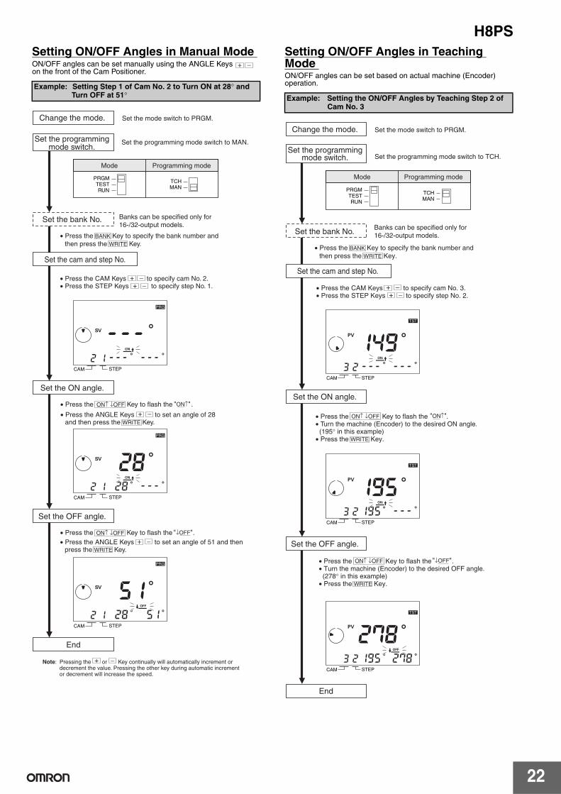
Setting ON/OFF Angles in Manual Mode ON/OFF angles can be set manually using the ANGLE Keys on the front of the Cam Positioner.
Setting ON/OFF Angles in Teaching Mode ON/OFF angles can be set based on actual machine (Encoder) operation. Example: Setting Step 1 of Cam No. 2 to Turn ON at 28° and
Turn OFF at 51°
Set the bank No.
Set the cam and step No.
Set the ON angle.
Set the OFF angle.
End
Change the mode.
Set the programming mode switch.
Set the mode switch to PRGM.
Set the programming mode switch to MAN.
Banks can be specified only for
16-/32-output models.
Note: Pressing the or Key continually will automatically increment or decrement the value. Pressing the other key during automatic increment or decrement will increase the speed.
• Press the BANK Key to specify the bank number and
then press the WRITE Key.
• Press the CAM Keys to specify cam No. 2.• Press the STEP Keys to specify step No. 1.
• Press the Key to flash the .
• Press the ANGLE Keys to set an angle of 28 and then press the WRITE Key.
• Press the Key to flash the .
• Press the ANGLE Keys to set an angle of 51 and then press the WRITE Key.
"↓OFF"
"ON↑"
ON↑ ↓OFF
ON↑ ↓OFF
Mode Programming mode
PRGMTESTRUN
TCHMAN
CAM STEP
PRG
CAM STEP
PRG
CAM STEP
PRG
Example: Setting the ON/OFF Angles by Teaching Step 2 of Cam No. 3
Set the bank No.
Set the cam and step No.
Set the ON angle.
Set the OFF angle.
End
Change the mode.
Set the programming mode switch.
• Press the Key to flash the . • Turn the machine (Encoder) to the desired ON angle. (195° in this example) • Press the WRITE Key.
• Press the Key to flash the . • Turn the machine (Encoder) to the desired OFF angle. (278° in this example) • Press the WRITE Key.
Set the mode switch to PRGM.
Set the programming mode switch to TCH.
Banks can be specified only for
16-/32-output models.
• Press the CAM Keys to specify cam No. 3. • Press the STEP Keys to specify step No. 2.
• Press the BANK Key to specify the bank number and
then press the WRITE Key.
Mode Programming mode
PRGMTESTRUN
TCHMAN
CAM STEP
TST
CAM STEP
TST
CAM STEP
TST
"ON↑"ON↑ ↓OFF
"↓OFF"ON↑ ↓OFF
H8PS
23
Setting ON/OFF Angles Using Support
Software
With 16-/32-output models, programs can be uploaded or downloaded easily with the optional Support Software (H8PS-SOFT-V1) by connecting a personal computer to the Cam Positioner using the USB cable (Recommended USB Cables: ELECOM CO.Ltd. U2C-MF20BK).
Support Software Functions
• Writing cam programs
• Setting functions
• Editing, saving, and printing programs
• Displaying and printing cam program operation charts
• Simple simulations of programs
Applicable OS: Windows 98, 2000, ME, or XP
Refer to the user’s manual for the Support Software for details.
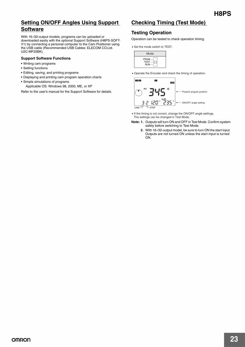
Checking Timing (Test Mode)
Testing Operation
Operation can be tested to check operation timing.
Note: 1. Outputs will turn ON and OFF in Test Mode. Confirm system safety before switching to Test Mode.
2. With 16-/32-output model, be sure to turn ON the start input. Outputs are not turned ON unless the start input is turned ON.
Mode
PRGMTESTRUN
CAM STEP
1 2 7TST
• Set the mode switch to TEST.
• Operate the Encoder and check the timing of operation.
Present angular position
ON/OFF angle setting
• If the timing is not correct, change the ON/OFF angle settings.
The settings can be changed in Test Mode.
H8PS
24
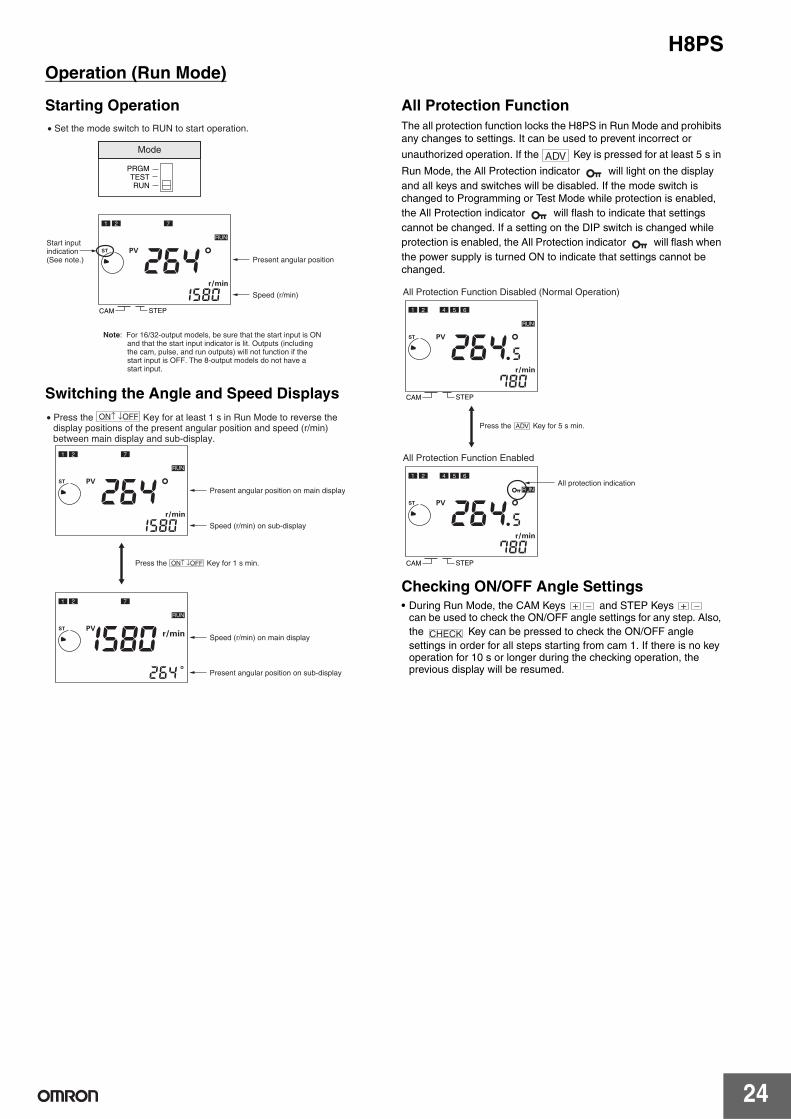
Operation (Run Mode)
Starting Operation
Switching the Angle and Speed Displays
All Protection Function
The all protection function locks the H8PS in Run Mode and prohibits any changes to settings. It can be used to prevent incorrect or
unauthorized operation. If the Key is pressed for at least 5 s in
Run Mode, the All Protection indicator will light on the display
and all keys and switches will be disabled. If the mode switch is changed to Programming or Test Mode while protection is enabled,
the All Protection indicator will flash to indicate that settings
cannot be changed. If a setting on the DIP switch is changed while
protection is enabled, the All Protection indicator will flash when
the power supply is turned ON to indicate that settings cannot be changed.
Checking ON/OFF Angle Settings• During Run Mode, the CAM Keys and STEP Keys
can be used to check the ON/OFF angle settings for any step. Also,
the Key can be pressed to check the ON/OFF angle
settings in order for all steps starting from cam 1. If there is no key operation for 10 s or longer during the checking operation, the previous display will be resumed.
Note: For 16/32-output models, be sure that the start input is ON and that the start input indicator is lit. Outputs (including the cam, pulse, and run outputs) will not function if the start input is OFF. The 8-output models do not have a start input.
Mode
PRGMTESTRUN
RUN
1 2 7
CAM STEP
• Set the mode switch to RUN to start operation.
Present angular position
Speed (r/min)
Start input indication (See note.)
• Press the Key for at least 1 s in Run Mode to reverse the display positions of the present angular position and speed (r/min) between main display and sub-display.
RUN
RUN
1 2 7
1 2 7
Present angular position on main display
Speed (r/min) on sub-display
Speed (r/min) on main display
Present angular position on sub-display
Press the Key for 1 s min.
ON↑ ↓OFF
ON↑ ↓OFF
ADV
Press the ADV Key for 5 s min.
All Protection Function Disabled (Normal Operation)
All Protection Function Enabled
RUN
CAM STEP
1 2 4 5 6
RUN
CAM STEP
1 2 4 5 6
All protection indication
CHECK
H8PS
25
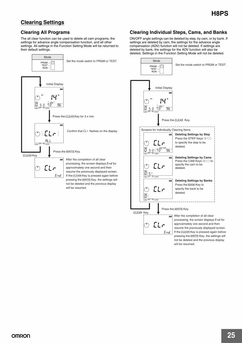
Clearing Settings
Clearing All Programs
The all clear function can be used to delete all cam programs, the settings for advance angle compensation function, and all other settings. All settings in the Function Setting Mode will be returned to their default settings.
Clearing Individual Steps, Cams, and Banks
ON/OFF angle settings can be deleted by step, by cam, or by bank. If settings are deleted by cam, the settings for the advance angle compensation (ADV) function will not be deleted. If settings are deleted by bank, the settings for the ADV function will also be deleted. Settings in the Function Setting Mode will not be deleted.
Initial Display
Set the mode switch to PRGM or TEST.
Press the WRITE Key.
CLEAR Key
Press the CLEAR Key for 3 s min.
Confirm that clr flashes on the display.
After the completion of all clear
processing, the screen displays end for
approximately one second and then
resume the previously displayed screen.
If the CLEAR Key is pressed again before
pressing the WRITE Key, the settings will
not be deleted and the previous display
will be resumed.
Mode
PRGMTESTRUN
CAM STEP
PRG
CAM STEP
PRG
PRG
Initial Display
Screens for Individually Clearing Items
Set the mode switch to PRGM or TEST.
Press the WRITE Key.
Press the CLEAR Key.
Deleting Settings by Step
Press the STEP Keys
to specify the step to be
deleted.
Deleting Settings by Cams
Press the CAM Keys to
specify the cam to be
deleted.
Deleting Settings by Banks
Press the BANK Key to
specify the bank to be
deleted.
CLEAR Key.After the completion of all clear
processing, the screen displays end for
approximately one second and then
resume the previously displayed screen.
If the CLEAR Key is pressed again before
pressing the WRITE Key, the settings will
not be deleted and the previous display
will be resumed.
Mode
PRGMTESTRUN
CAM STEP
PRG
CAM STEP
PRG
CAM STEP
PRG
CAM STEP
PRG
PRG