Embed Size (px)
Citation preview
CSM_NX-AD_DA_DS_E_2_2
1
NX-series Analog I/O Unit
NX-AD/DAAnalog inputs and outputs to meet all machine control needs, from general purpose to high-speed synchronous control• Connect to other NX I/O Units and EtherCAT Coupler
Units using the high-speed NX-bus• Separate modules for voltage and current
Features• Up to eight analog inputs per unit (NX-AD)• Up to four analog outputs per unit (NX-DA)• Free-run refreshing or synchronous I/O refreshing with the NX1P2 CPU Unit or EtherCAT Coupler Unit• Sampling times down to 10 μs per channel and high resolution of 1/30,000• Single-ended or differential input (NX-AD)• Selecting channel to use, moving average, input disconnection detection, over range/under range detection, and
user calibration• Detachable front connector with screwless Push-In Plus terminals for easy installation and maintenance• Compact with a width of 12 mm per unit• Connect to the CJ PLC using the EtherNet/IPTM bus coupler
Sysmac is a trademark or registered trademark of OMRON Corporation in Japan and other countries for OMRON factory automation products.EtherCAT is a registered trademark and patented technology, licensed by Beckhoff Automation GmbH, Germany.EtherNet/IPTM is a trademark of ODVA.Other company names and product names in this document are the trademarks or registered trademarks of their respective companies.
NX-AD/DA
2
System ConfigurationsConnected to a CPU Unit or Communication Control UnitThe following figure shows a system configuration when NX Units are connected to an NX-series CPU Unit.
Note: For whether an NX Unit can be connected to the CPU Unit, refer to the version information.
Connected to an EtherCAT Coupler UnitThe following figure shows an example of the system configuration when an EtherCAT Coupler Unit is used as a Communications Coupler Unit.
*1. The connection method for the Sysmac Studio depends on the model of the CPU Unit or Industrial PC.*2. An EtherCAT Slave Terminal cannot be connected to any of the OMRON CJ1W-NC@81/@82 Position Control Units even though they can
operate as EtherCAT masters.Note: For whether an NX Unit can be connected to the Communications Coupler Unit, refer to the version information.
Support software(Sysmac Studio)
End Cover
NX Units
NX Units
Built-in EtherCAT port
NX-series CPU Unit
EtherCAT Slave Terminal
Connection to built-in EtherNet/IP port
● CPU Rack
NX1P2-@@@@@@@
EtherCAT
EtherCAT Coupler Unit
EtherCAT master *2NJ/NX-series CPU Unit, NY-series Industrial PC, or master from another manufacturer
Communications cableEthernet cables
NX Series EtherCAT Coupler UnitNX-ECC20@
●EtherCAT Slave Terminal
Support software(Sysmac Studio)
Support software(Sysmac Studio)
End CoverNX Units
Built-in EtherCAT port
Connection to peripheral USB port or built-in EtherNet/IPTM port on CPU Unit or Industrial PC *1
Connection to peripheral USB port on EtherCAT Coupler Unit
Peripheral USB port.
ESI files
.xml
ESI files
.xml
3
NX-AD/DA
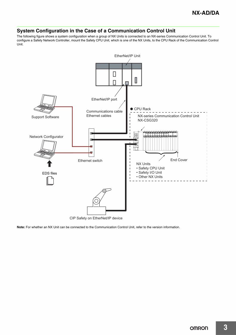
System Configuration in the Case of a Communication Control UnitThe following figure shows a system configuration when a group of NX Units is connected to an NX-series Communication Control Unit. To configure a Safety Network Controller, mount the Safety CPU Unit, which is one of the NX Units, to the CPU Rack of the Communication Control Unit.
Note: For whether an NX Unit can be connected to the Communication Control Unit, refer to the version information.
EtherNet/IP Unit
Communications cable Ethernet cables
EDS files
EtherNet/IP port
Network Configurator
CPU Rack
Ethernet switch
CIP Safety on EtherNet/IP device
Support Software NX-series Communication Control UnitNX-CSG320
End CoverNX Units• Safety CPU Unit• Safety I/O Unit• Other NX Units
NX-AD/DA
4
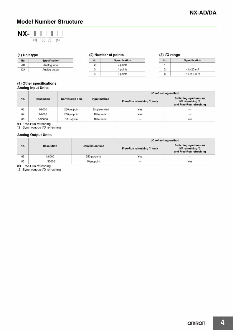
Model Number Structure
NX-@@@@@@(1) (2) (3) (4)
(1) Unit typeNo. Specification
AD Analog input
DA Analog output
(2) Number of pointsNo. Specification2 2 points
3 4 points
4 8 points
(3) I/O rangeNo. Specification1 ---
2 4 to 20 mA
6 -10 to +10 V
(4) Other specificationsAnalog Input Units
*1 Free-Run refreshing*2 Synchronous I/O refreshing
Analog Output Units
*1 Free-Run refreshing*2 Synchronous I/O refreshing
No. Resolution Conversion time Input method
I/O refreshing method
Free-Run refreshing *1 onlySwitching synchronous
I/O refreshing *2 and Free-Run refreshing
03 1/8000 250 μs/point Single-ended Yes ---
04 1/8000 250 μs/point Differential Yes ---
08 1/30000 10 μs/point Differential --- Yes
No. Resolution Conversion time
I/O refreshing method
Free-Run refreshing *1 onlySwitching synchronous
I/O refreshing *2 and Free-Run refreshing
03 1/8000 250 μs/point Yes ---
05 1/30000 10 μs/point --- Yes
5
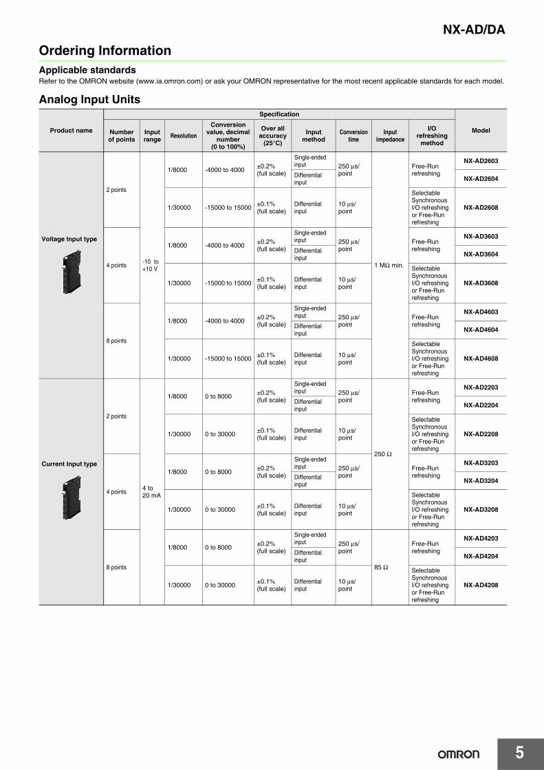
NX-AD/DAOrdering InformationApplicable standardsRefer to the OMRON website (www.ia.omron.com) or ask your OMRON representative for the most recent applicable standards for each model.
Analog Input Units
Product name
Specification
ModelNumber of points
Input range Resolution
Conversion value, decimal
number(0 to 100%)
Over all accuracy
(25°C)
Input method
Conversion time
Input impedance
I/O refreshing
method
Voltage Input type
2 points
-10 to +10 V
1/8000 -4000 to 4000 ±0.2%(full scale)
Single-ended input 250 μs/
point
1 MΩ min.
Free-Run refreshing
NX-AD2603
Differential input NX-AD2604
1/30000 -15000 to 15000 ±0.1%(full scale)
Differential input
10 μs/point
Selectable Synchronous I/O refreshing or Free-Run refreshing
NX-AD2608
4 points
1/8000 -4000 to 4000 ±0.2%(full scale)
Single-ended input 250 μs/
pointFree-Run refreshing
NX-AD3603
Differential input NX-AD3604
1/30000 -15000 to 15000 ±0.1%(full scale)
Differential input
10 μs/point
Selectable SynchronousI/O refreshing or Free-Run refreshing
NX-AD3608
8 points
1/8000 -4000 to 4000 ±0.2%(full scale)
Single-ended input 250 μs/
pointFree-Run refreshing
NX-AD4603
Differential input NX-AD4604
1/30000 -15000 to 15000 ±0.1%(full scale)
Differential input
10 μs/point
Selectable Synchronous I/O refreshing or Free-Run refreshing
NX-AD4608
Current Input type
2 points
4 to 20 mA
1/8000 0 to 8000 ±0.2%(full scale)
Single-ended input 250 μs/
point
250 Ω
Free-Run refreshing
NX-AD2203
Differential input NX-AD2204
1/30000 0 to 30000 ±0.1%(full scale)
Differential input
10 μs/point
Selectable Synchronous I/O refreshing or Free-Run refreshing
NX-AD2208
4 points
1/8000 0 to 8000 ±0.2%(full scale)
Single-ended input 250 μs/
pointFree-Run refreshing
NX-AD3203
Differential input NX-AD3204
1/30000 0 to 30000 ±0.1%(full scale)
Differential input
10 μs/point
Selectable Synchronous I/O refreshing or Free-Run refreshing
NX-AD3208
8 points
1/8000 0 to 8000 ±0.2%(full scale)
Single-ended input 250 μs/
point
85 Ω
Free-Run refreshing
NX-AD4203
Differential input NX-AD4204
1/30000 0 to 30000 ±0.1%(full scale)
Differential input
10 μs/point
Selectable Synchronous I/O refreshing or Free-Run refreshing
NX-AD4208
NX-AD/DA
6
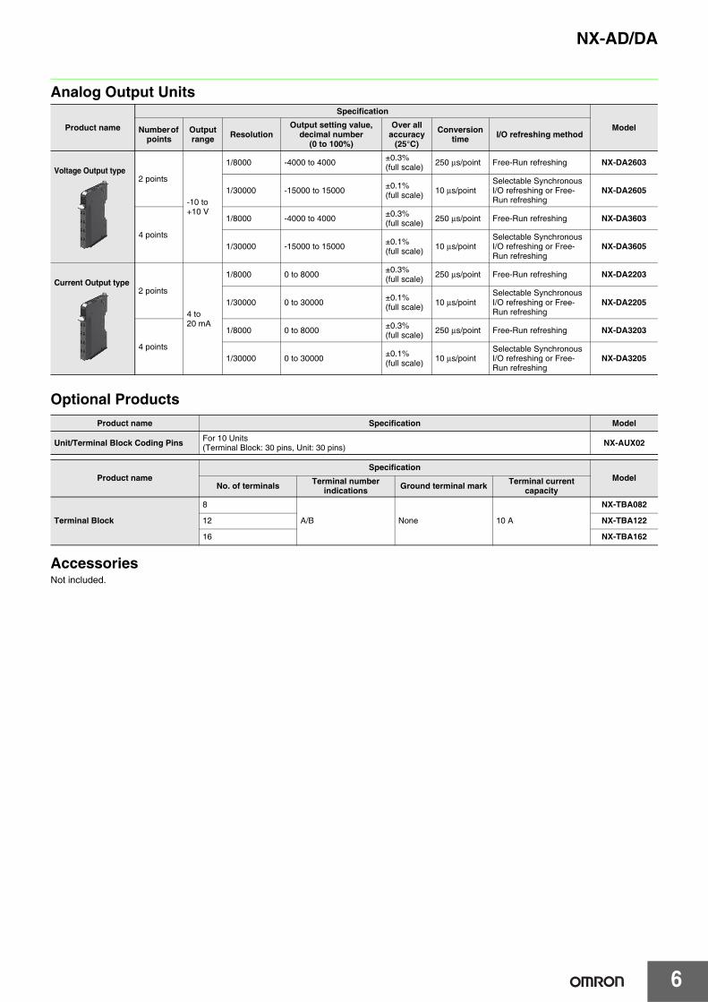
Analog Output Units
Optional Products
AccessoriesNot included.
Product name
Specification
ModelNumber of points
Output range Resolution
Output setting value, decimal number
(0 to 100%)
Over all accuracy
(25°C)
Conversion time I/O refreshing method
Voltage Output type2 points
-10 to +10 V
1/8000 -4000 to 4000 ±0.3%(full scale) 250 μs/point Free-Run refreshing NX-DA2603
1/30000 -15000 to 15000 ±0.1%(full scale) 10 μs/point
Selectable Synchronous I/O refreshing or Free-Run refreshing
NX-DA2605
4 points
1/8000 -4000 to 4000 ±0.3%(full scale) 250 μs/point Free-Run refreshing NX-DA3603
1/30000 -15000 to 15000 ±0.1%(full scale) 10 μs/point
Selectable Synchronous I/O refreshing or Free-Run refreshing
NX-DA3605
Current Output type2 points
4 to 20 mA
1/8000 0 to 8000 ±0.3%(full scale) 250 μs/point Free-Run refreshing NX-DA2203
1/30000 0 to 30000 ±0.1%(full scale) 10 μs/point
Selectable Synchronous I/O refreshing or Free-Run refreshing
NX-DA2205
4 points
1/8000 0 to 8000 ±0.3%(full scale) 250 μs/point Free-Run refreshing NX-DA3203
1/30000 0 to 30000 ±0.1%(full scale) 10 μs/point
Selectable Synchronous I/O refreshing or Free-Run refreshing
NX-DA3205
Product name Specification Model
Unit/Terminal Block Coding Pins For 10 Units(Terminal Block: 30 pins, Unit: 30 pins) NX-AUX02
Product nameSpecification
ModelNo. of terminals Terminal number
indications Ground terminal mark Terminal current capacity
Terminal Block
8
A/B None 10 A
NX-TBA082
12 NX-TBA122
16 NX-TBA162
7
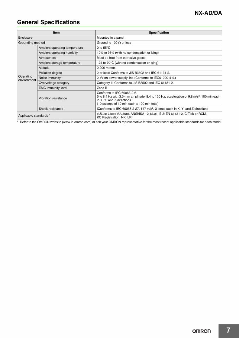
NX-AD/DAGeneral Specifications
* Refer to the OMRON website (www.ia.omron.com) or ask your OMRON representative for the most recent applicable standards for each model.
Item SpecificationEnclosure Mounted in a panel
Grounding method Ground to 100 Ω or less
Operating environment
Ambient operating temperature 0 to 55°C
Ambient operating humidity 10% to 95% (with no condensation or icing)
Atmosphere Must be free from corrosive gases.
Ambient storage temperature −25 to 70°C (with no condensation or icing)
Altitude 2,000 m max.
Pollution degree 2 or less: Conforms to JIS B3502 and IEC 61131-2.
Noise immunity 2 kV on power supply line (Conforms to IEC61000-4-4.)
Overvoltage category Category II: Conforms to JIS B3502 and IEC 61131-2.
EMC immunity level Zone B
Vibration resistance
Conforms to IEC 60068-2-6.5 to 8.4 Hz with 3.5-mm amplitude, 8.4 to 150 Hz, acceleration of 9.8 m/s2, 100 min each in X, Y, and Z directions (10 sweeps of 10 min each = 100 min total)
Shock resistance IConforms to IEC 60068-2-27. 147 m/s2, 3 times each in X, Y, and Z directions
Applicable standards * cULus: Listed (UL508), ANSI/ISA 12.12.01, EU: EN 61131-2, C-Tick or RCM, KC Registration, NK, LR
NX-AD/DA
8
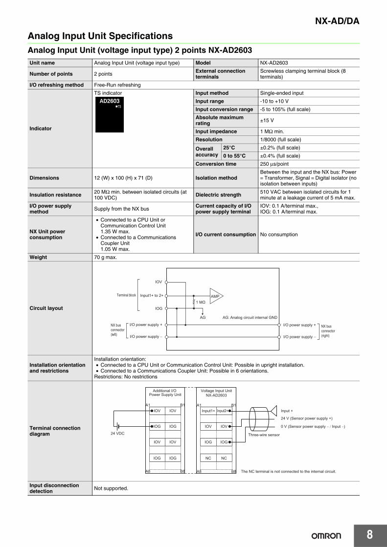
Analog Input Unit SpecificationsAnalog Input Unit (voltage input type) 2 points NX-AD2603Unit name Analog Input Unit (voltage input type) Model NX-AD2603
Number of points 2 points External connection terminals
Screwless clamping terminal block (8 terminals)
I/O refreshing method Free-Run refreshing
Indicator
TS indicator Input method Single-ended input
Input range -10 to +10 V
Input conversion range -5 to 105% (full scale)
Absolute maximum rating ±15 V
Input impedance 1 MΩ min.
Resolution 1/8000 (full scale)
Overall accuracy
25°C ±0.2% (full scale)
0 to 55°C ±0.4% (full scale)
Conversion time 250 μs/point
Dimensions 12 (W) x 100 (H) x 71 (D) Isolation methodBetween the input and the NX bus: Power = Transformer, Signal = Digital isolator (no isolation between inputs)
Insulation resistance 20 MΩ min. between isolated circuits (at 100 VDC) Dielectric strength 510 VAC between isolated circuits for 1
minute at a leakage current of 5 mA max.
I/O power supply method Supply from the NX bus Current capacity of I/O
power supply terminalIOV: 0.1 A/terminal max.,IOG: 0.1 A/terminal max.
NX Unit power consumption
• Connected to a CPU Unit or Communication Control Unit1.35 W max.
• Connected to a Communications Coupler Unit1.05 W max.
I/O current consumption No consumption
Weight 70 g max.
Circuit layout
Installation orientation and restrictions
Installation orientation:• Connected to a CPU Unit or Communication Control Unit: Possible in upright installation.• Connected to a Communications Coupler Unit: Possible in 6 orientations.
Restrictions: No restrictions
Terminal connection diagram
Input disconnection detection Not supported.
AG: Analog circuit internal GND
AMP
IOV
Input1+ to 2+
IOG
AG
NX bus connector (left)
Terminal block
I/O power supply +
I/O power supply −
I/O power supply +
I/O power supply −
NX bus connector (right)
1 MΩ
IOV
IOG
IOV
IOG
IOV
IOG
IOV
IOG
A1 B1
A8 B8
24 VDC
A1 B1
A8 B8
IOV
IOG
NC
IOV
IOG
NC
Input +
24 V (Sensor power supply +)
0 V (Sensor power supply − / Input −)
Three-wire sensor
Additional I/O Power Supply Unit
Input1+ Input2+
Voltage Input UnitNX-AD2603
The NC terminal is not connected to the internal circuit.
NX-AD/DA
9
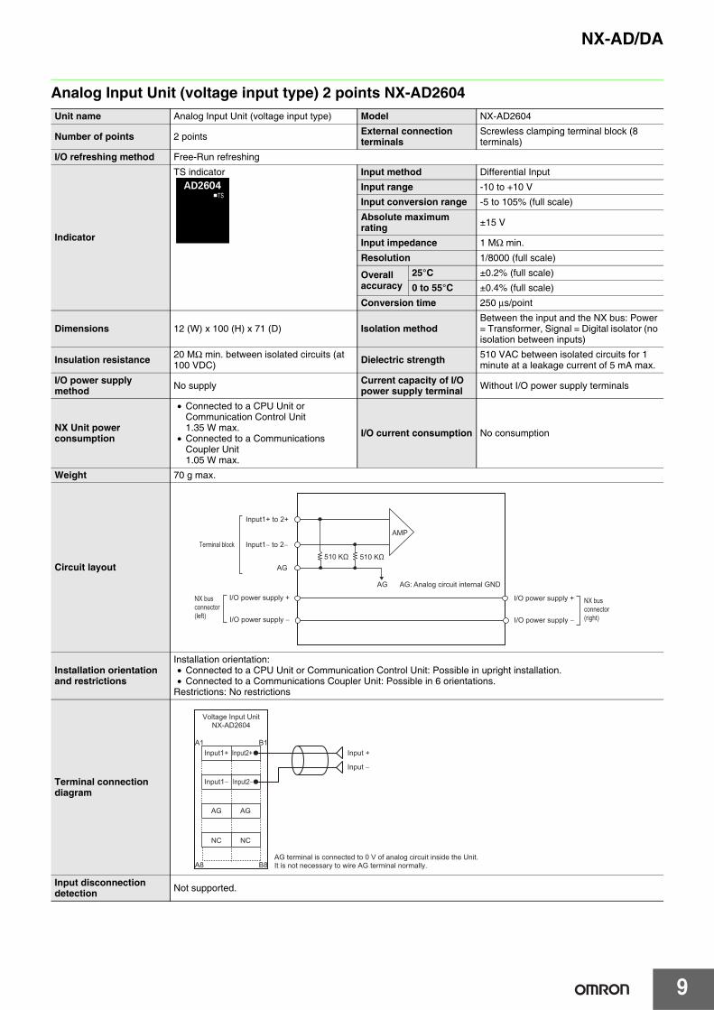
Analog Input Unit (voltage input type) 2 points NX-AD2604Unit name Analog Input Unit (voltage input type) Model NX-AD2604
Number of points 2 points External connection terminals
Screwless clamping terminal block (8 terminals)
I/O refreshing method Free-Run refreshing
Indicator
TS indicator Input method Differential Input
Input range -10 to +10 V
Input conversion range -5 to 105% (full scale)
Absolute maximum rating ±15 V
Input impedance 1 MΩ min.
Resolution 1/8000 (full scale)
Overall accuracy
25°C ±0.2% (full scale)
0 to 55°C ±0.4% (full scale)
Conversion time 250 μs/point
Dimensions 12 (W) x 100 (H) x 71 (D) Isolation methodBetween the input and the NX bus: Power = Transformer, Signal = Digital isolator (no isolation between inputs)
Insulation resistance 20 MΩ min. between isolated circuits (at 100 VDC) Dielectric strength 510 VAC between isolated circuits for 1
minute at a leakage current of 5 mA max.
I/O power supply method No supply Current capacity of I/O
power supply terminal Without I/O power supply terminals
NX Unit power consumption
• Connected to a CPU Unit or Communication Control Unit1.35 W max.
• Connected to a Communications Coupler Unit1.05 W max.
I/O current consumption No consumption
Weight 70 g max.
Circuit layout
Installation orientation and restrictions
Installation orientation:• Connected to a CPU Unit or Communication Control Unit: Possible in upright installation.• Connected to a Communications Coupler Unit: Possible in 6 orientations.
Restrictions: No restrictions
Terminal connection diagram
Input disconnection detection Not supported.
AMP
AG
AG
510 KΩ510 KΩ
Input1+ to 2+
NX bus connector (left)
Terminal block
I/O power supply +
I/O power supply −
I/O power supply +
I/O power supply −
NX bus connector (right)
Input1− to 2−
AG: Analog circuit internal GND
A1 B1
A8 B8
AG
NC
AG
NC
AG terminal is connected to 0 V of analog circuit inside the Unit.It is not necessary to wire AG terminal normally.
Input +
Input −
Input1+
Voltage Input UnitNX-AD2604
Input1−
Input2+
Input2−
10
NX-AD/DA
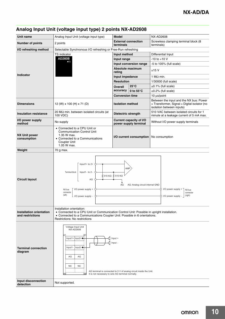
Analog Input Unit (voltage input type) 2 points NX-AD2608Unit name Analog Input Unit (voltage input type) Model NX-AD2608
Number of points 2 points External connection terminals
Screwless clamping terminal block (8 terminals)
I/O refreshing method Selectable Synchronous I/O refreshing or Free-Run refreshing
Indicator
TS indicator Input method Differential Input
Input range -10 to +10 V
Input conversion range -5 to 105% (full scale)
Absolute maximum rating ±15 V
Input impedance 1 MΩ min.
Resolution 1/30000 (full scale)
Overall accuracy
25°C ±0.1% (full scale)
0 to 55°C ±0.2% (full scale)
Conversion time 10 μs/point
Dimensions 12 (W) x 100 (H) x 71 (D) Isolation methodBetween the input and the NX bus: Power = Transformer, Signal = Digital isolator (no isolation between inputs)
Insulation resistance 20 MΩ min. between isolated circuits (at 100 VDC) Dielectric strength 510 VAC between isolated circuits for 1
minute at a leakage current of 5 mA max.
I/O power supply method No supply Current capacity of I/O
power supply terminal Without I/O power supply terminals
NX Unit power consumption
• Connected to a CPU Unit or Communication Control Unit1.35 W max.
• Connected to a Communications Coupler Unit1.05 W max.
I/O current consumption No consumption
Weight 70 g max.
Circuit layout
Installation orientation and restrictions
Installation orientation:• Connected to a CPU Unit or Communication Control Unit: Possible in upright installation.• Connected to a Communications Coupler Unit: Possible in 6 orientations.
Restrictions: No restrictions
Terminal connection diagram
Input disconnection detection Not supported.
AMP
AG
AG510 KΩ510 KΩ
Input1+ to 2+
NX bus connector (left)
Terminal block
I/O power supply +
I/O power supply −
I/O power supply +
I/O power supply −
NX bus connector (right)
Input1− to 2−
AG: Analog circuit internal GND
A1 B1
A8 B8
AG
NC
AG
NC
AG terminal is connected to 0 V of analog circuit inside the Unit.It is not necessary to wire AG terminal normally.
Input +
Input −
Input1+
Voltage Input UnitNX-AD2608
Input1−
Input2+
Input2−
NX-AD/DA
11
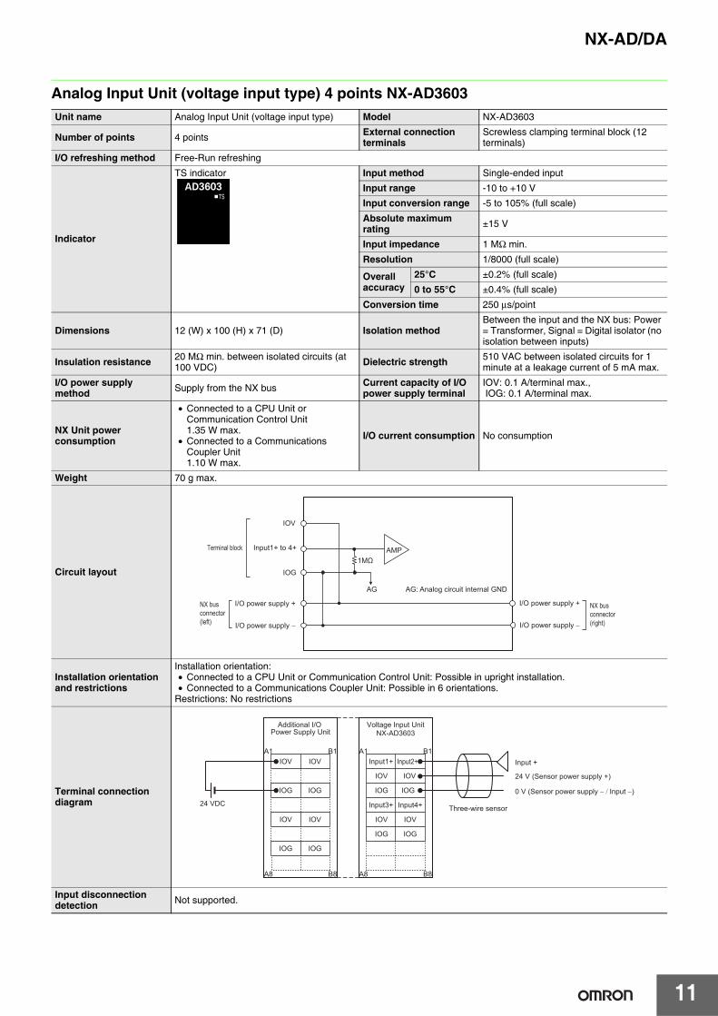
Analog Input Unit (voltage input type) 4 points NX-AD3603Unit name Analog Input Unit (voltage input type) Model NX-AD3603
Number of points 4 points External connection terminals
Screwless clamping terminal block (12 terminals)
I/O refreshing method Free-Run refreshing
Indicator
TS indicator Input method Single-ended input
Input range -10 to +10 V
Input conversion range -5 to 105% (full scale)
Absolute maximum rating ±15 V
Input impedance 1 MΩ min.
Resolution 1/8000 (full scale)
Overall accuracy
25°C ±0.2% (full scale)
0 to 55°C ±0.4% (full scale)
Conversion time 250 μs/point
Dimensions 12 (W) x 100 (H) x 71 (D) Isolation methodBetween the input and the NX bus: Power = Transformer, Signal = Digital isolator (no isolation between inputs)
Insulation resistance 20 MΩ min. between isolated circuits (at 100 VDC) Dielectric strength 510 VAC between isolated circuits for 1
minute at a leakage current of 5 mA max.
I/O power supply method Supply from the NX bus Current capacity of I/O
power supply terminalIOV: 0.1 A/terminal max., IOG: 0.1 A/terminal max.
NX Unit power consumption
• Connected to a CPU Unit or Communication Control Unit1.35 W max.
• Connected to a Communications Coupler Unit1.10 W max.
I/O current consumption No consumption
Weight 70 g max.
Circuit layout
Installation orientation and restrictions
Installation orientation:• Connected to a CPU Unit or Communication Control Unit: Possible in upright installation.• Connected to a Communications Coupler Unit: Possible in 6 orientations.
Restrictions: No restrictions
Terminal connection diagram
Input disconnection detection Not supported.
AG
1MΩAMP
IOV
IOG
Input1+ to 4+
NX bus connector (left)
Terminal block
I/O power supply +
I/O power supply −
I/O power supply +
I/O power supply −
NX bus connector (right)
AG: Analog circuit internal GND
Input +
24 V (Sensor power supply +)
0 V (Sensor power supply − / Input −)
Three-wire sensor
IOV
IOG
IOV
IOG
IOV
IOG
IOV
IOG
IOG
IOV
IOV
A1 B1
A8 B8
IOG
IOG
IOV
IOV
IOG
24 VDC
A1 B1
A8 B8
Additional I/O Power Supply Unit
Input1+ Input2+
Voltage Input UnitNX-AD3603
Input3+ Input4+
NX-AD/DA
12
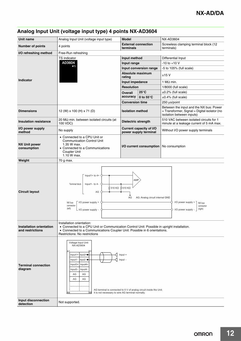
Analog Input Unit (voltage input type) 4 points NX-AD3604Unit name Analog Input Unit (voltage input type) Model NX-AD3604
Number of points 4 points External connection terminals
Screwless clamping terminal block (12 terminals)
I/O refreshing method Free-Run refreshing
Indicator
TS indicator Input method Differential Input
Input range -10 to +10 V
Input conversion range -5 to 105% (full scale)
Absolute maximum rating ±15 V
Input impedance 1 MΩ min.
Resolution 1/8000 (full scale)
Overall accuracy
25°C ±0.2% (full scale)
0 to 55°C ±0.4% (full scale)
Conversion time 250 μs/point
Dimensions 12 (W) x 100 (H) x 71 (D) Isolation methodBetween the input and the NX bus: Power = Transformer, Signal = Digital isolator (no isolation between inputs)
Insulation resistance 20 MΩ min. between isolated circuits (at 100 VDC) Dielectric strength 510 VAC between isolated circuits for 1
minute at a leakage current of 5 mA max.
I/O power supply method No supply Current capacity of I/O
power supply terminal Without I/O power supply terminals
NX Unit power consumption
• Connected to a CPU Unit or Communication Control Unit1.35 W max.
• Connected to a Communications Coupler Unit1.10 W max.
I/O current consumption No consumption
Weight 70 g max.
Circuit layout
Installation orientation and restrictions
Installation orientation:• Connected to a CPU Unit or Communication Control Unit: Possible in upright installation.• Connected to a Communications Coupler Unit: Possible in 6 orientations.
Restrictions: No restrictions
Terminal connection diagram
Input disconnection detection Not supported.
AMP
AG
AG
Input1+ to 4+
NX bus connector (left)
Terminal block
I/O power supply +
I/O power supply −
I/O power supply +
I/O power supply −
NX bus connector (right)
Input1− to 4−
510 KΩ510 KΩ
AG: Analog circuit internal GND
AG
A1 B1
A8 B8
AG
AG
AG
AG terminal is connected to 0 V of analog circuit inside the Unit.It is not necessary to wire AG terminal normally.
Input +
Input −
Input1+
Voltage Input UnitNX-AD3604
Input1−
Input2+
Input2−
Input3+
Input3−
Input4+
Input4−

NX-AD/DA
13
Analog Input Unit (voltage input type) 4 points NX-AD3608Unit name Analog Input Unit (voltage input type) Model NX-AD3608
Number of points 4 points External connection terminals
Screwless clamping terminal block (12 terminals)
I/O refreshing method Selectable Synchronous I/O refreshing or Free-Run refreshing
Indicator
TS indicator Input method Differential Input
Input range -10 to +10 V
Input conversion range -5 to 105% (full scale)
Absolute maximum rating ±15 V
Input impedance 1 MΩ min.
Resolution 1/30000 (full scale)
Overall accuracy
25°C ±0.1% (full scale)
0 to 55°C ±0.2% (full scale)
Conversion time 10 μs/point
Dimensions 12 (W) x 100 (H) x 71 (D) Isolation methodBetween the input and the NX bus: Power = Transformer, Signal = Digital isolator (no isolation between inputs)
Insulation resistance 20 MΩ min. between isolated circuits (at 100 VDC) Dielectric strength 510 VAC between isolated circuits for 1
minute at a leakage current of 5 mA max.
I/O power supply method No supply Current capacity of I/O
power supply terminal Without I/O power supply terminals
NX Unit power consumption
• Connected to a CPU Unit or Communication Control Unit1.45 W max.
• Connected to a Communications Coupler Unit1.10 W max.
I/O current consumption No consumption
Weight 70 g max.
Circuit layout
Installation orientation and restrictions
Installation orientation:• Connected to a CPU Unit or Communication Control Unit: Possible in upright installation.• Connected to a Communications Coupler Unit: Possible in 6 orientations.
Restrictions: No restrictions
Terminal connection diagram
Input disconnection detection Not supported.
AMP
AG
AG
Input1+ to 4+
NX bus connector (left)
Terminal block
I/O power supply +
I/O power supply −
I/O power supply +
I/O power supply −
NX bus connector (right)
Input1− to 4−
510 KΩ510 KΩ
AG: Analog circuit internal GND
AG
A1 B1
A8 B8
AG
AG
AG
AG terminal is connected to 0 V of analog circuit inside the Unit.It is not necessary to wire AG terminal normally.
Input +
Input −
Input1+
Voltage Input UnitNX-AD3608
Input1−
Input2+
Input2−
Input3+
Input3−
Input4+
Input4−
NX-AD/DA
14
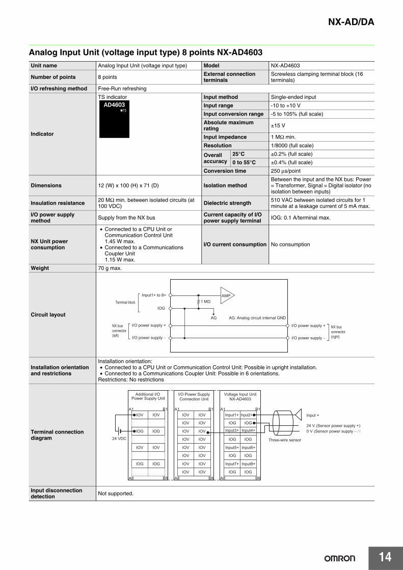
Analog Input Unit (voltage input type) 8 points NX-AD4603Unit name Analog Input Unit (voltage input type) Model NX-AD4603
Number of points 8 points External connection terminals
Screwless clamping terminal block (16 terminals)
I/O refreshing method Free-Run refreshing
Indicator
TS indicator Input method Single-ended input
Input range -10 to +10 V
Input conversion range -5 to 105% (full scale)
Absolute maximum rating ±15 V
Input impedance 1 MΩ min.
Resolution 1/8000 (full scale)
Overall accuracy
25°C ±0.2% (full scale)
0 to 55°C ±0.4% (full scale)
Conversion time 250 μs/point
Dimensions 12 (W) x 100 (H) x 71 (D) Isolation methodBetween the input and the NX bus: Power = Transformer, Signal = Digital isolator (no isolation between inputs)
Insulation resistance 20 MΩ min. between isolated circuits (at 100 VDC) Dielectric strength 510 VAC between isolated circuits for 1
minute at a leakage current of 5 mA max.
I/O power supply method Supply from the NX bus Current capacity of I/O
power supply terminal IOG: 0.1 A/terminal max.
NX Unit power consumption
• Connected to a CPU Unit or Communication Control Unit1.45 W max.
• Connected to a Communications Coupler Unit1.15 W max.
I/O current consumption No consumption
Weight 70 g max.
Circuit layout
Installation orientation and restrictions
Installation orientation:• Connected to a CPU Unit or Communication Control Unit: Possible in upright installation.• Connected to a Communications Coupler Unit: Possible in 6 orientations.
Restrictions: No restrictions
Terminal connection diagram
Input disconnection detection Not supported.
AG
AMP
NX bus connector (left)
Terminal block
I/O power supply +
I/O power supply −
I/O power supply +
I/O power supply −
NX bus connector (right)
1 MΩ
AG: Analog circuit internal GND
IOG
Input1+ to 8+
Input +
24 V (Sensor power supply +)0 V (Sensor power supply − / I
Three-wire sensor
IOV
IOV
IOV
IOV
IOV
IOV
IOV
IOV
IOV
IOV
IOV
IOV
IOV
IOV
IOV
IOV
IOG
A1 B1
A8 B8
IOG
IOG
IOG
IOG
IOG IOG
IOG
IOV
IOG
IOV
IOG
IOV
IOG
IOV
IOG
24 VDC
A1 B1
A8 B8
A1 B1
A8 B8
Additional I/O Power Supply Unit
Voltage Input UnitNX-AD4603
I/O Power SupplyConnection Unit
Input1+ Input2+
Input3+ Input4+
Input7+ Input8+
Input5+ Input6+
NX-AD/DA
15
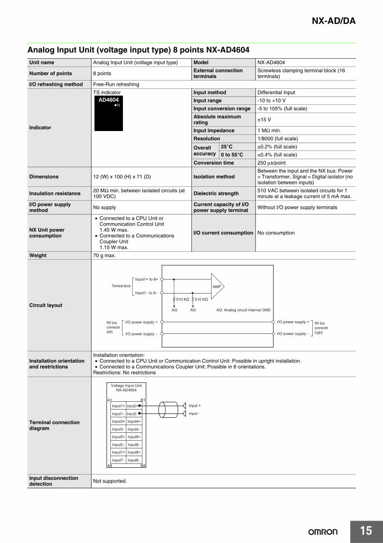
Analog Input Unit (voltage input type) 8 points NX-AD4604Unit name Analog Input Unit (voltage input type) Model NX-AD4604
Number of points 8 points External connection terminals
Screwless clamping terminal block (16 terminals)
I/O refreshing method Free-Run refreshing
Indicator
TS indicator Input method Differential Input
Input range -10 to +10 V
Input conversion range -5 to 105% (full scale)
Absolute maximum rating ±15 V
Input impedance 1 MΩ min.
Resolution 1/8000 (full scale)
Overall accuracy
25°C ±0.2% (full scale)
0 to 55°C ±0.4% (full scale)
Conversion time 250 μs/point
Dimensions 12 (W) x 100 (H) x 71 (D) Isolation methodBetween the input and the NX bus: Power = Transformer, Signal = Digital isolator (no isolation between inputs)
Insulation resistance 20 MΩ min. between isolated circuits (at 100 VDC) Dielectric strength 510 VAC between isolated circuits for 1
minute at a leakage current of 5 mA max.
I/O power supply method No supply Current capacity of I/O
power supply terminal Without I/O power supply terminals
NX Unit power consumption
• Connected to a CPU Unit or Communication Control Unit1.45 W max.
• Connected to a Communications Coupler Unit1.15 W max.
I/O current consumption No consumption
Weight 70 g max.
Circuit layout
Installation orientation and restrictions
Installation orientation:• Connected to a CPU Unit or Communication Control Unit: Possible in upright installation.• Connected to a Communications Coupler Unit: Possible in 6 orientations.
Restrictions: No restrictions
Terminal connection diagram
Input disconnection detection Not supported.
AMP
AGAG
Input1+ to 8+
NX bus connector (left)
Terminal block
I/O power supply +
I/O power supply −
I/O power supply +
I/O power supply −
NX bus connector (right)
Input1− to 8−
510 KΩ510 KΩ
AG: Analog circuit internal GND
A1 B1
A8 B8
Voltage Input UnitNX-AD4604
Input1+
Input1−
Input2+
Input2−
Input3+
Input3−
Input4+
Input4−
Input5+
Input5−
Input6+
Input6−
Input7+
Input7−
Input8+
Input8−
Input +
Input −
NX-AD/DA
16
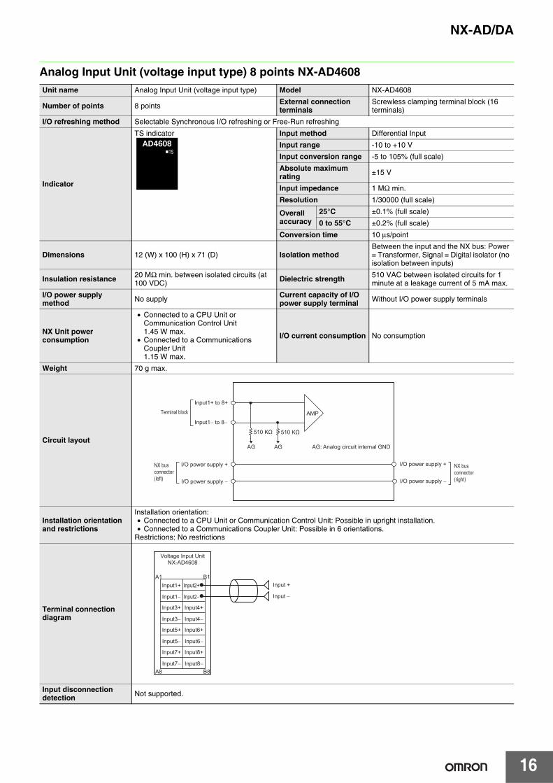
Analog Input Unit (voltage input type) 8 points NX-AD4608Unit name Analog Input Unit (voltage input type) Model NX-AD4608
Number of points 8 points External connection terminals
Screwless clamping terminal block (16 terminals)
I/O refreshing method Selectable Synchronous I/O refreshing or Free-Run refreshing
Indicator
TS indicator Input method Differential Input
Input range -10 to +10 V
Input conversion range -5 to 105% (full scale)
Absolute maximum rating ±15 V
Input impedance 1 MΩ min.
Resolution 1/30000 (full scale)
Overall accuracy
25°C ±0.1% (full scale)
0 to 55°C ±0.2% (full scale)
Conversion time 10 μs/point
Dimensions 12 (W) x 100 (H) x 71 (D) Isolation methodBetween the input and the NX bus: Power = Transformer, Signal = Digital isolator (no isolation between inputs)
Insulation resistance 20 MΩ min. between isolated circuits (at 100 VDC) Dielectric strength 510 VAC between isolated circuits for 1
minute at a leakage current of 5 mA max.
I/O power supply method No supply Current capacity of I/O
power supply terminal Without I/O power supply terminals
NX Unit power consumption
• Connected to a CPU Unit or Communication Control Unit1.45 W max.
• Connected to a Communications Coupler Unit1.15 W max.
I/O current consumption No consumption
Weight 70 g max.
Circuit layout
Installation orientation and restrictions
Installation orientation:• Connected to a CPU Unit or Communication Control Unit: Possible in upright installation.• Connected to a Communications Coupler Unit: Possible in 6 orientations.
Restrictions: No restrictions
Terminal connection diagram
Input disconnection detection Not supported.
AMP
AG AG
Input1+ to 8+
NX bus connector (left)
Terminal block
I/O power supply +
I/O power supply −
I/O power supply +
I/O power supply −
NX bus connector (right)
Input1− to 8−
510 KΩ510 KΩ
AG: Analog circuit internal GND
A1 B1
A8 B8
Voltage Input UnitNX-AD4608
Input1+
Input1−
Input2+
Input2−
Input3+
Input3−
Input4+
Input4−
Input5+
Input5−
Input6+
Input6−
Input7+
Input7−
Input8+
Input8−
Input +
Input −

NX-AD/DA
17
Analog Input Unit (current input type) 2 points NX-AD2203Unit name Analog Input Unit (current input type) Model NX-AD2203
Number of points 2 points External connection terminals
Screwless clamping terminal block (8 terminals)
I/O refreshing method Free-Run refreshing
Indicator
TS indicator Input method Single-ended input
Input range 4 to 20 mA
Input conversion range -5 to 105% (full scale)
Absolute maximum rating ±30 mA
Input impedance 250 Ω min.
Resolution 1/8000 (full scale)
Overall accuracy
25°C ±0.2% (full scale)
0 to 55°C ±0.4% (full scale)
Conversion time 250 μs/point
Dimensions 12 (W) x 100 (H) x 71 (D) Isolation methodBetween the input and the NX bus: Power = Transformer, Signal = Digital isolator (no isolation between inputs)
Insulation resistance 20 MΩ min. between isolated circuits (at 100 VDC) Dielectric strength 510 VAC between isolated circuits for 1
minute at a leakage current of 5 mA max.
I/O power supply method Supply from the NX bus Current capacity of I/O
power supply terminalIOV: 0.1 A/terminal max., IOG: 0.1 A/terminal max.
NX Unit power consumption
• Connected to a CPU Unit or Communication Control Unit1.25 W max.
• Connected to a Communications Coupler Unit0.90 W max.
I/O current consumption No consumption
Weight 70 g max.
Circuit layout
Installation orientation and restrictions
Installation orientation:• Connected to a CPU Unit or Communication Control Unit: Possible in upright installation.• Connected to a Communications Coupler Unit: Possible in 6 orientations.
Restrictions: No restrictions
Terminal connection diagram
Input disconnection detection Supported.
AMP
IOV
IOG
AG
250 ΩInput1+ to 2+
NX bus connector (left)
Terminal block
I/O power supply +
I/O power supply −
I/O power supply +
I/O power supply −
NX bus connector (right)
AG: Analog circuit internal GND
IOV
IOG
IOV
IOG
IOV
IOG
IOV
IOG
A1 B1
A8 B8
24 VDC
A1 B1
A8 B8
IOV
IOG
NC
IOV
IOG
NC
Input +
24 V (Sensor power supply +)
0 V (Sensor power supply − / Input −)
Three-wire sensor
Additional I/O Power Supply Unit
Input1+ Input2+
Current Input UnitNX-AD2203
The NC terminal is not connected to the internal circuit.
NX-AD/DA
18
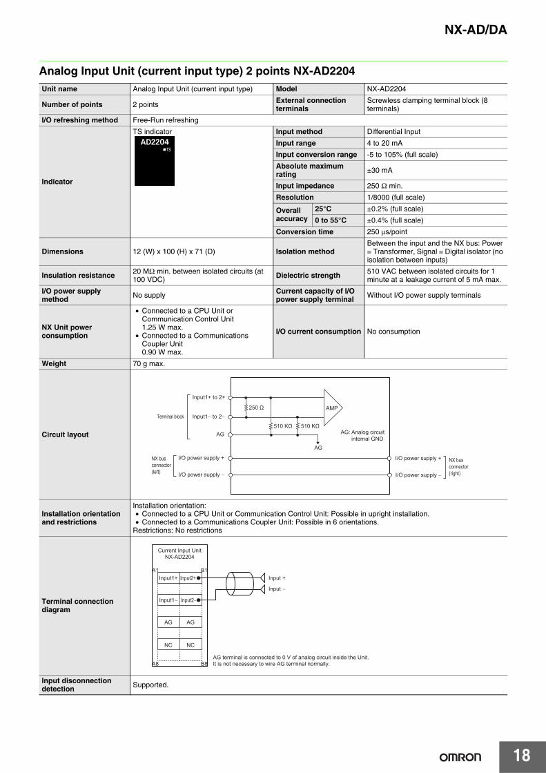
Analog Input Unit (current input type) 2 points NX-AD2204Unit name Analog Input Unit (current input type) Model NX-AD2204
Number of points 2 points External connection terminals
Screwless clamping terminal block (8 terminals)
I/O refreshing method Free-Run refreshing
Indicator
TS indicator Input method Differential Input
Input range 4 to 20 mA
Input conversion range -5 to 105% (full scale)
Absolute maximum rating ±30 mA
Input impedance 250 Ω min.
Resolution 1/8000 (full scale)
Overall accuracy
25°C ±0.2% (full scale)
0 to 55°C ±0.4% (full scale)
Conversion time 250 μs/point
Dimensions 12 (W) x 100 (H) x 71 (D) Isolation methodBetween the input and the NX bus: Power = Transformer, Signal = Digital isolator (no isolation between inputs)
Insulation resistance 20 MΩ min. between isolated circuits (at 100 VDC) Dielectric strength 510 VAC between isolated circuits for 1
minute at a leakage current of 5 mA max.
I/O power supply method No supply Current capacity of I/O
power supply terminal Without I/O power supply terminals
NX Unit power consumption
• Connected to a CPU Unit or Communication Control Unit1.25 W max.
• Connected to a Communications Coupler Unit0.90 W max.
I/O current consumption No consumption
Weight 70 g max.
Circuit layout
Installation orientation and restrictions
Installation orientation:• Connected to a CPU Unit or Communication Control Unit: Possible in upright installation.• Connected to a Communications Coupler Unit: Possible in 6 orientations.
Restrictions: No restrictions
Terminal connection diagram
Input disconnection detection Supported.
AMP
AG
AG
250 Ω
Input1+ to 2+
NX bus connector (left)
Terminal block
I/O power supply +
I/O power supply −
I/O power supply +
I/O power supply −
NX bus connector (right)
Input1− to 2−
510 KΩ510 KΩAG: Analog circuit internal GND
A1 B1
A8 B8
AG
NC
AG
NC
AG terminal is connected to 0 V of analog circuit inside the Unit.It is not necessary to wire AG terminal normally.
Input +
Input −
Input1+
Current Input UnitNX-AD2204
Input1−
Input2+
Input2−

NX-AD/DA
19
Analog Input Unit (current input type) 2 points NX-AD2208Unit name Analog Input Unit (current input type) Model NX-AD2208
Number of points 2 points External connection terminals
Screwless clamping terminal block (8 terminals)
I/O refreshing method Selectable Synchronous I/O refreshing or Free-Run refreshing
Indicator
TS indicator Input method Differential Input
Input range 4 to 20 mA
Input conversion range -5 to 105% (full scale)
Absolute maximum rating ±30 mA
Input impedance 250 Ω
Resolution 1/30000 (full scale)
Overall accuracy
25°C ±0.1% (full scale)
0 to 55°C ±0.2% (full scale)
Conversion time 10 μs/point
Dimensions 12 (W) x 100 (H) x 71 (D) Isolation methodBetween the input and the NX bus: Power = Transformer, Signal = Digital isolator (no isolation between inputs)
Insulation resistance 20 MΩ min. between isolated circuits (at 100 VDC) Dielectric strength 510 VAC between isolated circuits for 1
minute at a leakage current of 5 mA max.
I/O power supply method No supply Current capacity of I/O
power supply terminal Without I/O power supply terminals
NX Unit power consumption
• Connected to a CPU Unit or Communication Control Unit1.25 W max.
• Connected to a Communications Coupler Unit0.90 W max.
I/O current consumption No consumption
Weight 70 g max.
Circuit layout
Installation orientation and restrictions
Installation orientation:• Connected to a CPU Unit or Communication Control Unit: Possible in upright installation.• Connected to a Communications Coupler Unit: Possible in 6 orientations.
Restrictions: No restrictions
Terminal connection diagram
Input disconnection detection Supported.
AMP
AG
AG
250 Ω
Input1+ to 2+
NX bus connector (left)
Terminal block
I/O power supply +
I/O power supply −
I/O power supply +
I/O power supply −
NX bus connector (right)
Input1− to 2−
510 KΩ510 KΩAG: Analog circuit internal GND
A1 B1
A8 B8
AG
NC
AG
NC
AG terminal is connected to 0 V of analog circuit inside the Unit.It is not necessary to wire AG terminal normally.
Input +
Input −
Input1+
Current Input UnitNX-AD2208
Input1−
Input2+
Input2−

NX-AD/DA
20
Analog Input Unit (current input type) 4 points NX-AD3203Unit name Analog Input Unit (current input type) Model NX-AD3203
Number of points 4 points External connection terminals
Screwless clamping terminal block (12 terminals)
I/O refreshing method Free-Run refreshing
Indicator
TS indicator Input method Single-ended input
Input range 4 to 20 mA
Input conversion range -5 to 105% (full scale)
Absolute maximum rating ±30 mA
Input impedance 250 Ω min.
Resolution 1/8000 (full scale)
Overall accuracy
25°C ±0.2% (full scale)
0 to 55°C ±0.4% (full scale)
Conversion time 250 μs/point
Dimensions 12 (W) x 100 (H) x 71 (D) Isolation methodBetween the input and the NX bus: Power = Transformer, Signal = Digital isolator (no isolation between inputs)
Insulation resistance 20 MΩ min. between isolated circuits (at 100 VDC) Dielectric strength 510 VAC between isolated circuits for 1
minute at a leakage current of 5 mA max.
I/O power supply method Supply from the NX bus Current capacity of I/O
power supply terminalIOV: 0.1 A/terminal max., IOG: 0.1 A/terminal max.
NX Unit power consumption
• Connected to a CPU Unit or Communication Control Unit1.25 W max.
• Connected to a Communications Coupler Unit0.90 W max.
I/O current consumption No consumption
Weight 70 g max.
Circuit layout
Installation orientation and restrictions
Installation orientation:• Connected to a CPU Unit or Communication Control Unit: Possible in upright installation.• Connected to a Communications Coupler Unit: Possible in 6 orientations.
Restrictions: No restrictions
Terminal connection diagram
Input disconnection detection Supported.
AG
AMP
IOV
IOG
Input1+ to 4+
NX bus connector (left)
Terminal block
I/O power supply +
I/O power supply −
I/O power supply +
I/O power supply −
NX bus connector (right)
250 Ω
AG: Analog circuit internal GND
Input +
24 V (Sensor power supply +)
0 V (Sensor power supply − / Input −)
Three-wire sensor
IOV
IOG
IOV
IOG
IOV
IOG
IOV
IOG
IOG
IOV
IOV
A1 B1
A8 B8
IOG
IOG
IOV
IOV
IOG
24 VDC
A1 B1
A8 B8
Additional I/O Power Supply Unit
Current Input UnitNX-AD3203
Input1+ Input2+
Input3+ Input4+
21
NX-AD/DA
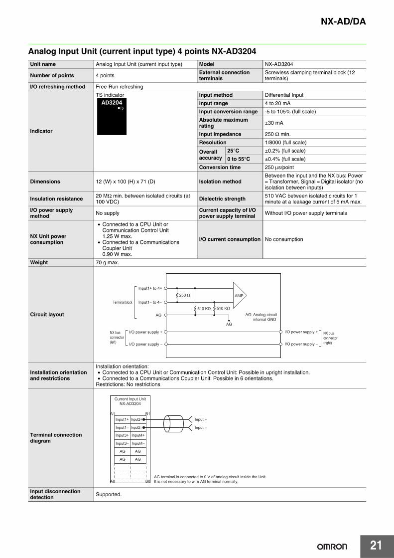
Analog Input Unit (current input type) 4 points NX-AD3204Unit name Analog Input Unit (current input type) Model NX-AD3204
Number of points 4 points External connection terminals
Screwless clamping terminal block (12 terminals)
I/O refreshing method Free-Run refreshing
Indicator
TS indicator Input method Differential Input
Input range 4 to 20 mA
Input conversion range -5 to 105% (full scale)
Absolute maximum rating ±30 mA
Input impedance 250 Ω min.
Resolution 1/8000 (full scale)
Overall accuracy
25°C ±0.2% (full scale)
0 to 55°C ±0.4% (full scale)
Conversion time 250 μs/point
Dimensions 12 (W) x 100 (H) x 71 (D) Isolation methodBetween the input and the NX bus: Power = Transformer, Signal = Digital isolator (no isolation between inputs)
Insulation resistance 20 MΩ min. between isolated circuits (at 100 VDC) Dielectric strength 510 VAC between isolated circuits for 1
minute at a leakage current of 5 mA max.
I/O power supply method No supply Current capacity of I/O
power supply terminal Without I/O power supply terminals
NX Unit power consumption
• Connected to a CPU Unit or Communication Control Unit1.25 W max.
• Connected to a Communications Coupler Unit0.90 W max.
I/O current consumption No consumption
Weight 70 g max.
Circuit layout
Installation orientation and restrictions
Installation orientation:• Connected to a CPU Unit or Communication Control Unit: Possible in upright installation.• Connected to a Communications Coupler Unit: Possible in 6 orientations.
Restrictions: No restrictions
Terminal connection diagram
Input disconnection detection Supported.
AMP
AG
AG
Input1+ to 4+
NX bus connector (left)
Terminal block
I/O power supply +
I/O power supply −
I/O power supply +
I/O power supply −
NX bus connector (right)
Input1− to 4−
510 KΩ510 KΩ
250 Ω
AG: Analog circuit internal GND
AG
A1 B1
A8 B8
AG
AG
AG
AG terminal is connected to 0 V of analog circuit inside the Unit.It is not necessary to wire AG terminal normally.
Input +
Input −
Input1+
Current Input UnitNX-AD3204
Input1−
Input2+
Input2−
Input3+
Input3−
Input4+
Input4−
NX-AD/DA
22
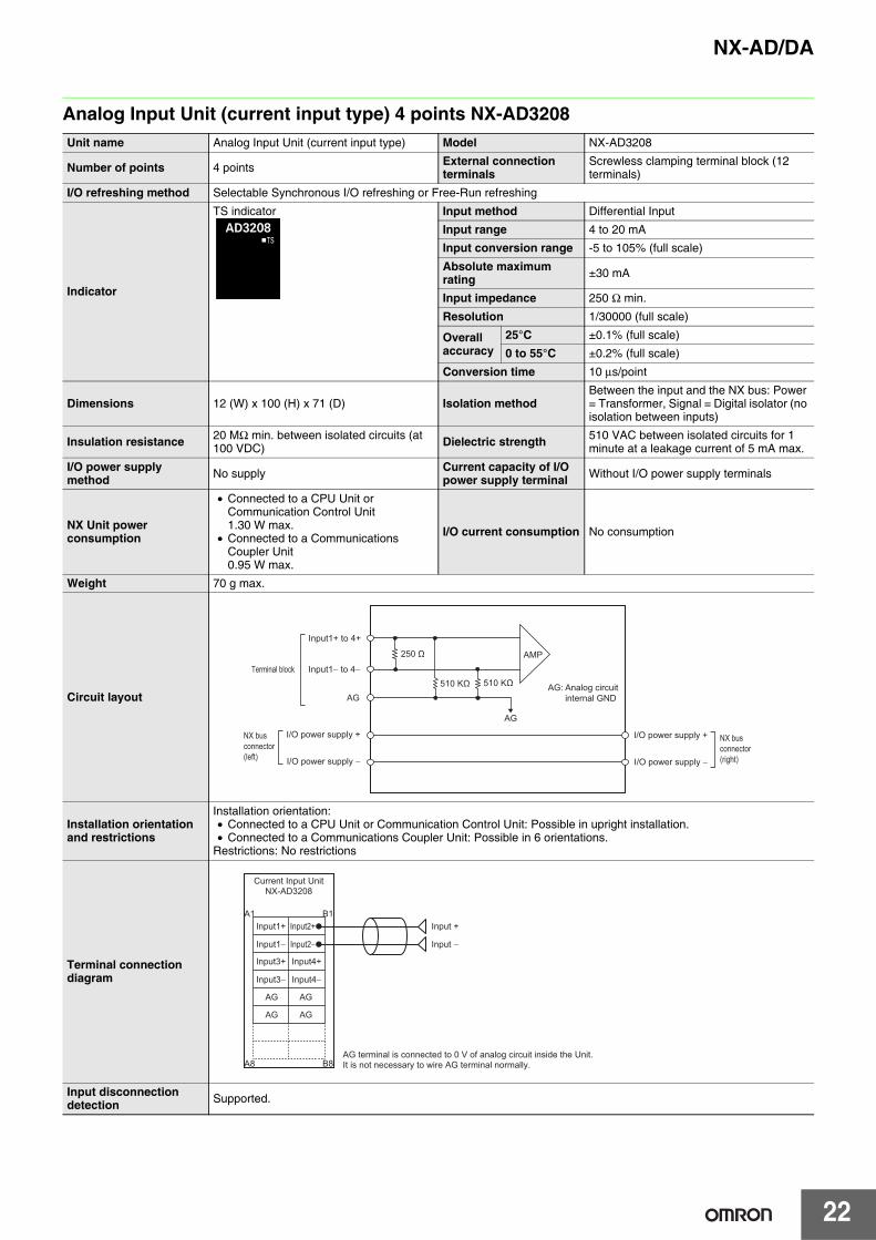
Analog Input Unit (current input type) 4 points NX-AD3208Unit name Analog Input Unit (current input type) Model NX-AD3208
Number of points 4 points External connection terminals
Screwless clamping terminal block (12 terminals)
I/O refreshing method Selectable Synchronous I/O refreshing or Free-Run refreshing
Indicator
TS indicator Input method Differential Input
Input range 4 to 20 mA
Input conversion range -5 to 105% (full scale)
Absolute maximum rating ±30 mA
Input impedance 250 Ω min.
Resolution 1/30000 (full scale)
Overall accuracy
25°C ±0.1% (full scale)
0 to 55°C ±0.2% (full scale)
Conversion time 10 μs/point
Dimensions 12 (W) x 100 (H) x 71 (D) Isolation methodBetween the input and the NX bus: Power = Transformer, Signal = Digital isolator (no isolation between inputs)
Insulation resistance 20 MΩ min. between isolated circuits (at 100 VDC) Dielectric strength 510 VAC between isolated circuits for 1
minute at a leakage current of 5 mA max.
I/O power supply method No supply Current capacity of I/O
power supply terminal Without I/O power supply terminals
NX Unit power consumption
• Connected to a CPU Unit or Communication Control Unit1.30 W max.
• Connected to a Communications Coupler Unit0.95 W max.
I/O current consumption No consumption
Weight 70 g max.
Circuit layout
Installation orientation and restrictions
Installation orientation:• Connected to a CPU Unit or Communication Control Unit: Possible in upright installation.• Connected to a Communications Coupler Unit: Possible in 6 orientations.
Restrictions: No restrictions
Terminal connection diagram
Input disconnection detection Supported.
AMP
AG
AG
Input1+ to 4+
NX bus connector (left)
Terminal block
I/O power supply +
I/O power supply −
I/O power supply +
I/O power supply −
NX bus connector (right)
Input1− to 4−
510 KΩ 510 KΩ
250 Ω
AG: Analog circuit internal GND
AG
A1 B1
A8 B8
AG
AG
AG
AG terminal is connected to 0 V of analog circuit inside the Unit.It is not necessary to wire AG terminal normally.
Input +
Input −
Input1+
Current Input UnitNX-AD3208
Input1−
Input2+
Input2−
Input3+
Input3−
Input4+
Input4−

23
NX-AD/DA
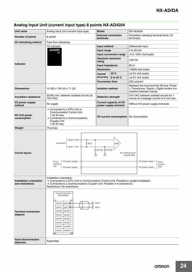
Analog Input Unit (current input type) 8 points NX-AD4203Unit name Analog Input Unit (current input type) Model NX-AD4203
Number of points 8 points External connection terminals
Screwless clamping terminal block (16 terminals)
I/O refreshing method Free-Run refreshing
Indicator
TS indicator Input method Single-ended input
Input range 4 to 20 mA
Input conversion range -5 to 105% (full scale)
Absolute maximum rating ±30 mA
Input impedance 85 Ω
Resolution 1/8000 (full scale)
Overall accuracy
25°C ±0.2% (full scale)
0 to 55°C ±0.4% (full scale)
Conversion time 250 μs/point
Dimensions 12 (W) x 100 (H) x 71 (D) Isolation methodBetween the input and the NX bus: Power = Transformer, Signal = Digital isolator (no isolation between inputs)
Insulation resistance 20 MΩ min. between isolated circuits (at 100 VDC) Dielectric strength 510 VAC between isolated circuits for 1
minute at a leakage current of 5 mA max.
I/O power supply method Supply from the NX bus Current capacity of I/O
power supply terminal IOV: 0.1 A/terminal max.
NX Unit power consumption
• Connected to a CPU Unit or Communication Control Unit1.40 W max.
• Connected to a Communications Coupler Unit1.05 W max.
I/O current consumption No consumption
Weight 70 g max.
Circuit layout
Installation orientation and restrictions
Installation orientation:• Connected to a CPU Unit or Communication Control Unit: Possible in upright installation.• Connected to a Communications Coupler Unit: Possible in 6 orientations.
Restrictions: No restrictions
Terminal connection diagram
Input disconnection detection Supported.
IOV
AMP
AG AG
Input1+ to 8+
NX bus connector (left)
Terminal block
I/O power supply +
I/O power supply −
I/O power supply +
I/O power supply −
NX bus connector (right)
85 ΩAG: Analog circuit internal GND
Input +
24 V (Sensor power supply +)0 V (Sensor power supply − / Input −)
Three-wire Sensor
IOG
IOG
IOG
IOG
IOG
IOG
IOG
IOG
IOG
IOG
IOG
IOG
IOG
IOG
IOG
IOG
IOV
A1 B1
A8 B8
IOV
IOV
IOV
IOV
IOV IOV
IOV
IOV
IOG
IOV
IOG
IOV
IOG
IOV
IOG
24 VDC
A1 B1
A8 B8
A1 B1
A8 B8
Additional I/O Power Supply Unit
Voltage Input UnitNX-AD4203
I/O Power SupplyConnection Unit
Input1+ Input2+
Input3+ Input4+
Input7+ Input8+
Input5+ Input6+
NX-AD/DA
24
Analog Input Unit (current input type) 8 points NX-AD4204Unit name Analog Input Unit (current input type) Model NX-AD4204
Number of points 8 points External connection terminals
Screwless clamping terminal block (16 terminals)
I/O refreshing method Free-Run refreshing
Indicator
TS indicator Input method Differential Input
Input range 4 to 20 mA
Input conversion range -5 to 105% (full scale)
Absolute maximum rating ±30 mA
Input impedance 85 Ω
Resolution 1/8000 (full scale)
Overall accuracy
25°C ±0.2% (full scale)
0 to 55°C ±0.4% (full scale)
Conversion time 250 μs/point
Dimensions 12 (W) x 100 (H) x 71 (D) Isolation methodBetween the input and the NX bus: Power = Transformer, Signal = Digital isolator (no isolation between inputs)
Insulation resistance 20 MΩ min. between isolated circuits (at 100 VDC) Dielectric strength 510 VAC between isolated circuits for 1
minute at a leakage current of 5 mA max.
I/O power supply method No supply Current capacity of I/O
power supply terminal Without I/O power supply terminals
NX Unit power consumption
• Connected to a CPU Unit or Communication Control Unit1.40 W max.
• Connected to a Communications Coupler Unit1.05 W max.
I/O current consumption No consumption
Weight 70 g max.
Circuit layout
Installation orientation and restrictions
Installation orientation:• Connected to a CPU Unit or Communication Control Unit: Possible in upright installation.• Connected to a Communications Coupler Unit: Possible in 6 orientations.
Restrictions: No restrictions
Terminal connection diagram
Input disconnection detection Supported.
AMP
AG AG
Input1+ to 8+
NX bus connector (left)
Terminal block
I/O power supply +
I/O power supply −
I/O power supply +
I/O power supply −
NX bus connector (right)
Input1− to 8−
510 KΩ510 KΩ
85 Ω
AG: Analog circuit internal GND
Input +
Input −
A1 B1
A8 B8
Current Input UnitNX-AD4204
Input1+
Input1−
Input2+
Input2−
Input3+
Input3−
Input4+
Input4−
Input5+
Input5−
Input6+
Input6−
Input7+
Input7−
Input8+
Input8−
25
NX-AD/DA
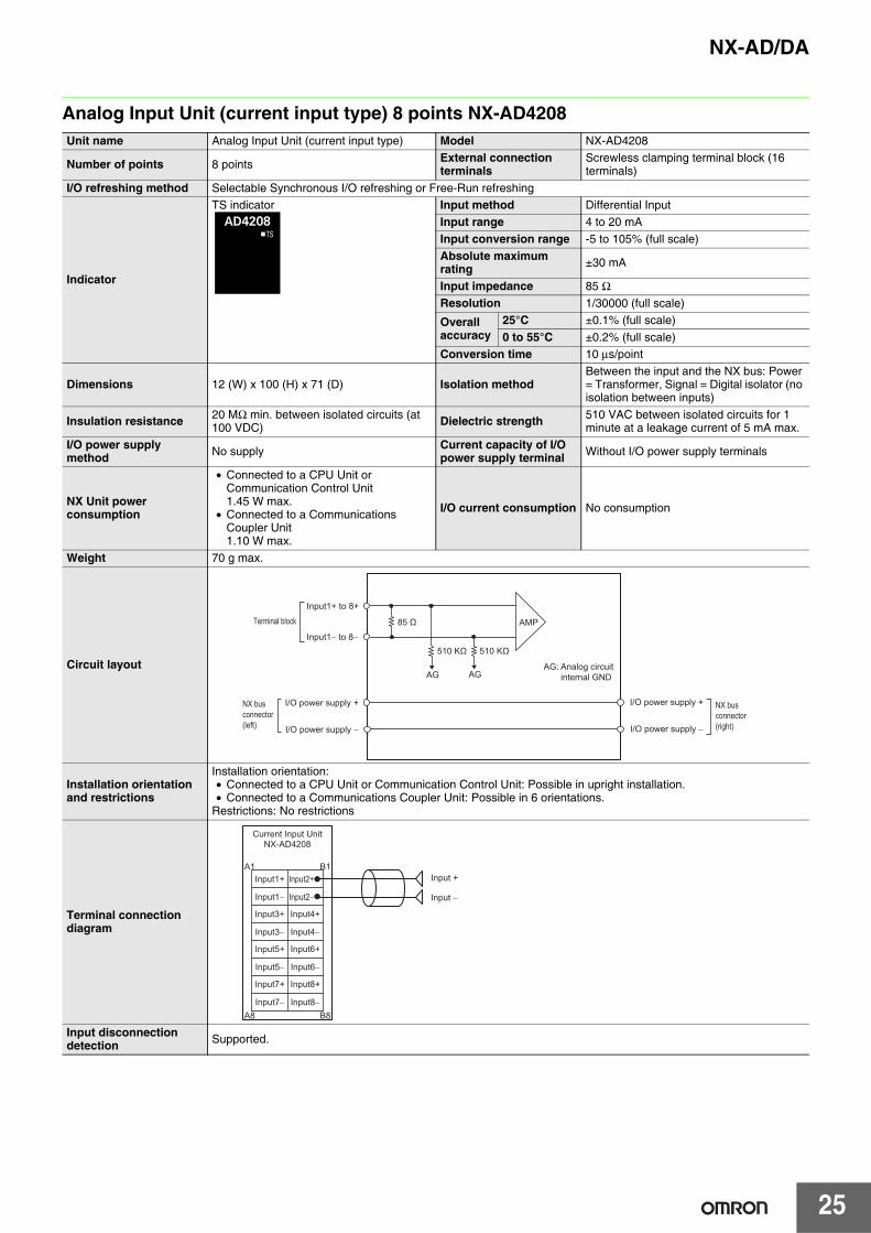
Analog Input Unit (current input type) 8 points NX-AD4208Unit name Analog Input Unit (current input type) Model NX-AD4208
Number of points 8 points External connection terminals
Screwless clamping terminal block (16 terminals)
I/O refreshing method Selectable Synchronous I/O refreshing or Free-Run refreshing
Indicator
TS indicator Input method Differential InputInput range 4 to 20 mAInput conversion range -5 to 105% (full scale)Absolute maximum rating ±30 mA
Input impedance 85 Ω Resolution 1/30000 (full scale)
Overall accuracy
25°C ±0.1% (full scale)0 to 55°C ±0.2% (full scale)
Conversion time 10 μs/point
Dimensions 12 (W) x 100 (H) x 71 (D) Isolation methodBetween the input and the NX bus: Power = Transformer, Signal = Digital isolator (no isolation between inputs)
Insulation resistance 20 MΩ min. between isolated circuits (at 100 VDC) Dielectric strength 510 VAC between isolated circuits for 1
minute at a leakage current of 5 mA max.I/O power supply method No supply Current capacity of I/O
power supply terminal Without I/O power supply terminals
NX Unit power consumption
• Connected to a CPU Unit or Communication Control Unit1.45 W max.
• Connected to a Communications Coupler Unit1.10 W max.
I/O current consumption No consumption
Weight 70 g max.
Circuit layout
Installation orientation and restrictions
Installation orientation:• Connected to a CPU Unit or Communication Control Unit: Possible in upright installation.• Connected to a Communications Coupler Unit: Possible in 6 orientations.
Restrictions: No restrictions
Terminal connection diagram
Input disconnection detection Supported.
AMP
AG AG
Input1+ to 8+
NX bus connector (left)
Terminal block
I/O power supply +
I/O power supply −
I/O power supply +
I/O power supply −
NX bus connector (right)
Input1− to 8−
510 KΩ510 KΩ
85 Ω
AG: Analog circuit internal GND
Input +
Input −
A1 B1
A8 B8
Current Input UnitNX-AD4208
Input1+
Input1−
Input2+
Input2−
Input3+
Input3−
Input4+
Input4−
Input5+
Input5−
Input6+
Input6−
Input7+
Input7−
Input8+
Input8−
NX-AD/DA
26
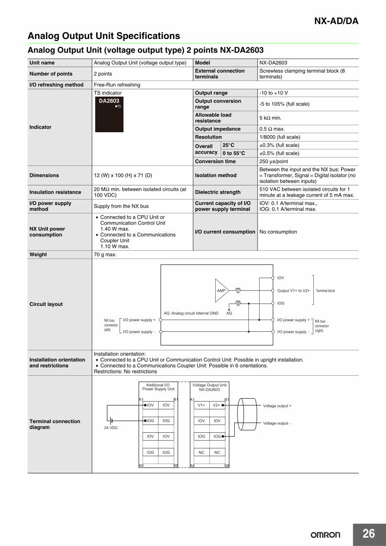
Analog Output Unit SpecificationsAnalog Output Unit (voltage output type) 2 points NX-DA2603Unit name Analog Output Unit (voltage output type) Model NX-DA2603
Number of points 2 points External connection terminals
Screwless clamping terminal block (8 terminals)
I/O refreshing method Free-Run refreshing
Indicator
TS indicator Output range -10 to +10 V
Output conversion range -5 to 105% (full scale)
Allowable load resistance 5 kΩ min.
Output impedance 0.5 Ω max.
Resolution 1/8000 (full scale)
Overall accuracy
25°C ±0.3% (full scale)
0 to 55°C ±0.5% (full scale)
Conversion time 250 μs/point
Dimensions 12 (W) x 100 (H) x 71 (D) Isolation methodBetween the input and the NX bus: Power = Transformer, Signal = Digital isolator (no isolation between inputs)
Insulation resistance 20 MΩ min. between isolated circuits (at 100 VDC) Dielectric strength 510 VAC between isolated circuits for 1
minute at a leakage current of 5 mA max.
I/O power supply method Supply from the NX bus Current capacity of I/O
power supply terminalIOV: 0.1 A/terminal max.,IOG: 0.1 A/terminal max.
NX Unit power consumption
• Connected to a CPU Unit or Communication Control Unit1.40 W max.
• Connected to a Communications Coupler Unit1.10 W max.
I/O current consumption No consumption
Weight 70 g max.
Circuit layout
Installation orientation and restrictions
Installation orientation:• Connected to a CPU Unit or Communication Control Unit: Possible in upright installation.• Connected to a Communications Coupler Unit: Possible in 6 orientations.
Restrictions: No restrictions
Terminal connection diagram
AMP
IOV
AG
IOG
Output V1+ to V2+
NX bus connector (left)
Terminal block
I/O power supply +
I/O power supply −
I/O power supply +
I/O power supply −
NX bus connector (right)
AG: Analog circuit internal GND
Voltage output +
Voltage output −
IOV
IOG
IOV
IOG
IOV
IOG
IOV
IOG
A1 B1
A8 B8
24 VDC
A1 B1
A8 B8
V1+
IOV
IOG
NC
V2+
IOV
IOG
NC
Additional I/O Power Supply Unit
Voltage Output UnitNX-DA2603

27
NX-AD/DA
Analog Output Unit (voltage output type) 2 points NX-DA2605Unit name Analog Output Unit (voltage output type) Model NX-DA2605
Number of points 2 points External connection terminals
Screwless clamping terminal block (8 terminals)
I/O refreshing method Selectable Synchronous I/O refreshing or Free-Run refreshing
Indicator
TS indicator Output range -10 to +10 V
Output conversion range -5 to 105% (full scale)
Allowable load resistance 5 kΩ min.
Output impedance 0.5 Ω max.
Resolution 1/30000 (full scale)
Overall accuracy
25°C ±0.1% (full scale)
0 to 55°C ±0.3% (full scale)
Conversion time 10 μs/point
Dimensions 12 (W) x 100 (H) x 71 (D) Isolation methodBetween the input and the NX bus: Power = Transformer, Signal = Digital isolator (no isolation between inputs)
Insulation resistance 20 MΩ min. between isolated circuits (at 100 VDC) Dielectric strength 510 VAC between isolated circuits for 1
minute at a leakage current of 5 mA max.
I/O power supply method Supply from the NX bus Current capacity of I/O
power supply terminalIOV: 0.1 A/terminal max.,IOG: 0.1 A/terminal max.
NX Unit power consumption
• Connected to a CPU Unit or Communication Control Unit1.40 W max.
• Connected to a Communications Coupler Unit1.10 W max.
I/O current consumption No consumption
Weight 70 g max.
Circuit layout
Installation orientation and restrictions
Installation orientation:• Connected to a CPU Unit or Communication Control Unit: Possible in upright installation.• Connected to a Communications Coupler Unit: Possible in 6 orientations.
Restrictions: No restrictions
Terminal connection diagram
AMP
AG
IOV
IOG
Output V1+ to V2+
NX bus connector (left)
Terminal block
I/O power supply +
I/O power supply −
I/O power supply +
I/O power supply −
NX bus connector (right)
AG: Analog circuit internal GND
Voltage output +
Voltage output −
IOV
IOG
IOV
IOG
IOV
IOG
IOV
IOG
A1 B1
A8 B8
24 VDC
A1 B1
A8 B8
V1+
IOV
IOG
NC
V2+
IOV
IOG
NC
Additional I/O Power Supply Unit
Voltage Output UnitNX-DA2605

NX-AD/DA
28
Analog Output Unit (voltage output type) 4 points NX-DA3603Unit name Analog Output Unit (voltage output type) Model NX-DA3603
Number of points 4 points External connection terminals
Screwless clamping terminal block (12 terminals)
I/O refreshing method Free-Run refreshing
Indicator
TS indicator Output range -10 to +10 V
Output conversion range -5 to 105% (full scale)
Allowable load resistance 5 kΩ min.
Output impedance 0.5 Ω max.
Resolution 1/8000 (full scale)
Overall accuracy
25°C ±0.3% (full scale)
0 to 55°C ±0.5% (full scale)
Conversion time 250 μs/point
Dimensions 12 (W) x 100 (H) x 71 (D) Isolation methodBetween the input and the NX bus: Power = Transformer, Signal = Digital isolator (no isolation between inputs)
Insulation resistance 20 MΩ min. between isolated circuits (at 100 VDC) Dielectric strength 510 VAC between isolated circuits for 1
minute at a leakage current of 5 mA max.
I/O power supply method Supply from the NX bus Current capacity of I/O
power supply terminalIOV: 0.1 A/terminal max.,IOG: 0.1 A/terminal max.
NX Unit power consumption
• Connected to a CPU Unit or Communication Control Unit1.35 W max.
• Connected to a Communications Coupler Unit1.25 W max.
I/O current consumption No consumption
Weight 70 g max.
Circuit layout
Installation orientation and restrictions
Installation orientation:• Connected to a CPU Unit or Communication Control Unit: Possible in upright installation.• Connected to a Communications Coupler Unit: Possible in 6 orientations.
Restrictions: No restrictions
Terminal connection diagram
AMP
AG
IOV
IOG
Output V1+ to V4+
NX bus connector (left)
Terminal block
I/O power supply +
I/O power supply −
I/O power supply +
I/O power supply −
NX bus connector (right)
AG: Analog circuit internal GND
Voltage output +
Voltage output −
IOV
IOG
IOV
IOG
IOV
IOG
IOV
IOG
V1+
IOG
IOV
IOV
A1 B1
A8 B8
IOG
V2+
IOG
IOV
IOV
IOG
24 VDC
A1 B1
A8 B8
V3+ V4+
Additional I/O Power Supply Unit
Voltage Output UnitNX-DA3603

29
NX-AD/DA
Analog Output Unit (voltage output type) 4 points NX-DA3605Unit name Analog Output Unit (voltage output type) Model NX-DA3605
Number of points 4 points External connection terminals
Screwless clamping terminal block (12 terminals)
I/O refreshing method Selectable Synchronous I/O refreshing or Free-Run refreshing
Indicator
TS indicator Output range -10 to +10 V
Output conversion range -5 to 105% (full scale)
Allowable load resistance 5 kΩ min.
Output impedance 0.5 Ω max.
Resolution 1/30000 (full scale)
Overall accuracy
25°C ±0.1% (full scale)
0 to 55°C ±0.3% (full scale)
Conversion time 10 μs/point
Dimensions 12 (W) x 100 (H) x 71 (D) Isolation methodBetween the input and the NX bus: Power = Transformer, Signal = Digital isolator (no isolation between inputs)
Insulation resistance 20 MΩ min. between isolated circuits (at 100 VDC) Dielectric strength 510 VAC between isolated circuits for 1
minute at a leakage current of 5 mA max.
I/O power supply method Supply from the NX bus Current capacity of I/O
power supply terminalIOV: 0.1 A/terminal max.,IOG: 0.1 A/terminal max.
NX Unit power consumption
• Connected to a CPU Unit or Communication Control Unit1.60 W max.
• Connected to a Communications Coupler Unit1.25 W max.
I/O current consumption No consumption
Weight 70 g max.
Circuit layout
Installation orientation and restrictions
Installation orientation:• Connected to a CPU Unit or Communication Control Unit: Possible in upright installation.• Connected to a Communications Coupler Unit: Possible in 6 orientations.
Restrictions: No restrictions
Terminal connection diagram
AMP
AG
IOV
IOG
Output V1+ to V4+
NX bus connector (left)
Terminal block
I/O power supply +
I/O power supply −
I/O power supply +
I/O power supply −
NX bus connector (right)
AG: Analog circuit internal GND
Voltage output +
Voltage output −
IOV
IOG
IOV
IOG
IOV
IOG
IOV
IOG
V1+
IOG
IOV
IOV
A1 B1
A8 B8
IOG
V2+
IOG
IOV
IOV
IOG
24 VDC
A1 B1
A8 B8
V3+ V4+
Additional I/O Power Supply Unit
Voltage Output UnitNX-DA3605
NX-AD/DA
30
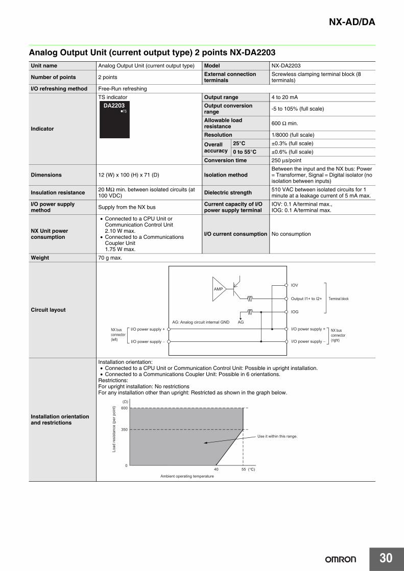
Analog Output Unit (current output type) 2 points NX-DA2203Unit name Analog Output Unit (current output type) Model NX-DA2203
Number of points 2 points External connection terminals
Screwless clamping terminal block (8 terminals)
I/O refreshing method Free-Run refreshing
Indicator
TS indicator Output range 4 to 20 mA
Output conversion range -5 to 105% (full scale)
Allowable load resistance 600 Ω min.
Resolution 1/8000 (full scale)
Overall accuracy
25°C ±0.3% (full scale)
0 to 55°C ±0.6% (full scale)
Conversion time 250 μs/point
Dimensions 12 (W) x 100 (H) x 71 (D) Isolation methodBetween the input and the NX bus: Power = Transformer, Signal = Digital isolator (no isolation between inputs)
Insulation resistance 20 MΩ min. between isolated circuits (at 100 VDC) Dielectric strength 510 VAC between isolated circuits for 1
minute at a leakage current of 5 mA max.
I/O power supply method Supply from the NX bus Current capacity of I/O
power supply terminalIOV: 0.1 A/terminal max.,IOG: 0.1 A/terminal max.
NX Unit power consumption
• Connected to a CPU Unit or Communication Control Unit2.10 W max.
• Connected to a Communications Coupler Unit1.75 W max.
I/O current consumption No consumption
Weight 70 g max.
Circuit layout
Installation orientation and restrictions
Installation orientation:• Connected to a CPU Unit or Communication Control Unit: Possible in upright installation.• Connected to a Communications Coupler Unit: Possible in 6 orientations.
Restrictions:For upright installation: No restrictionsFor any installation other than upright: Restricted as shown in the graph below.
IOV
AG
IOG
AMP
Output I1+ to I2+
NX bus connector (left)
Terminal block
I/O power supply +
I/O power supply −
I/O power supply +
I/O power supply −
NX bus connector (right)
AG: Analog circuit internal GND
Ambient operating temperature
Use it within this range.
Load
resi
stan
ce (p
er p
oint
)
40 55
0
350
600
(°C)
(Ω)

31
NX-AD/DA
Terminal connection diagram
Current output +
Current output −
IOV
IOG
IOV
IOG
IOV
IOG
IOV
IOG
A1 B1
A8 B8
24 VDC
A1 B1
A8 B8
I1+
IOV
IOG
NC
I2+
IOV
IOG
NC
Additional I/O Power Supply Unit
Current Output UnitNX-DA2203

NX-AD/DA
32
Analog Output Unit (current output type) 2 points NX-DA2205Unit name Analog Output Unit (current output type) Model NX-DA2205
Number of points 2 points External connection terminals
Screwless clamping terminal block (8 terminals)
I/O refreshing method Selectable Synchronous I/O refreshing or Free-Run refreshing
Indicator
TS indicator Output range 4 to 20 mA
Output conversion range -5 to 105% (full scale)
Allowable load resistance 600 Ω min.
Resolution 1/30000 (full scale)
Overall accuracy
25°C ±0.1% (full scale)
0 to 55°C ±0.3% (full scale)
Conversion time 10 μs/point
Dimensions 12 (W) x 100 (H) x 71 (D) Isolation methodBetween the input and the NX bus: Power = Transformer, Signal = Digital isolator (no isolation between inputs)
Insulation resistance 20 MΩ min. between isolated circuits (at 100 VDC) Dielectric strength 510 VAC between isolated circuits for 1
minute at a leakage current of 5 mA max.
I/O power supply method Supply from the NX bus Current capacity of I/O
power supply terminalIOV: 0.1 A/terminal max.,IOG: 0.1 A/terminal max.
NX Unit power consumption
• Connected to a CPU Unit or Communication Control Unit2.10 W max.
• Connected to a Communications Coupler Unit1.75 W max.
I/O current consumption No consumption
Weight 70 g max.
Circuit layout
Installation orientation and restrictions
Installation orientation:• Connected to a CPU Unit or Communication Control Unit: Possible in upright installation.• Connected to a Communications Coupler Unit: Possible in 6 orientations.
Restrictions:For upright installation: No restrictionsFor any installation other than upright: Restricted as shown in the graph below.
IOV
AG
IOG
AMP
Output I1+ to I2+
NX bus connector (left)
Terminal block
I/O power supply +
I/O power supply −
I/O power supply +
I/O power supply −
NX bus connector (right)
AG: Analog circuit internal GND
Ambient operating temperature
Use it within this range.
Load
resi
stan
ce (p
er p
oint
)
40 55
0
350
600
(°C)
(Ω)

33
NX-AD/DA
Terminal connection diagram
IOV
IOG
IOV
IOG
IOV
IOG
IOV
IOG
A1 B1
A8 B8
24 VDC
A1 B1
A8 B8
I1+
IOV
IOG
NC
I2+
IOV
IOG
NC
Current output +
Current output −
Additional I/O Power Supply Unit
Current Output UnitNX-DA2205

NX-AD/DA
34
Analog Output Unit (current output type) 4 points NX-DA3203Unit name Analog Output Unit (current output type) Model NX-DA3203
Number of points 4 points External connection terminals
Screwless clamping terminal block (12 terminals)
I/O refreshing method Free-Run refreshing
Indicator
TS indicator Output range 4 to 20 mA
Output conversion range -5 to 105% (full scale)
Allowable load resistance 350 Ω min.
Resolution 1/8000 (full scale)
Overall accuracy
25°C ±0.3% (full scale)
0 to 55°C ±0.6% (full scale)
Conversion time 250 μs/point
Dimensions 12 (W) x 100 (H) x 71 (D) Isolation methodBetween the input and the NX bus: Power = Transformer, Signal = Digital isolator (no isolation between inputs)
Insulation resistance 20 MΩ min. between isolated circuits (at 100 VDC) Dielectric strength 510 VAC between isolated circuits for 1
minute at a leakage current of 5 mA max.
I/O power supply method Supply from the NX bus Current capacity of I/O
power supply terminalIOV: 0.1 A/terminal max.,IOG: 0.1 A/terminal max.
NX Unit power consumption
• Connected to a CPU Unit or Communication Control Unit2.10 W max.
• Connected to a Communications Coupler Unit1.80 W max.
I/O current consumption No consumption
Weight 70 g max.
Circuit layout
Installation orientation and restrictions
Installation orientation:• Connected to a CPU Unit or Communication Control Unit: Possible in upright installation.• Connected to a Communications Coupler Unit: Possible in 6 orientations.
Restrictions:For upright installation: No restrictionsFor any installation other than upright: Restricted as shown in the graph below.
IOV
AG
IOG
AMP
Output I1+ to I4+
NX bus connector (left)
Terminal block
I/O power supply +
I/O power supply −
I/O power supply +
I/O power supply −
NX bus connector (right)
AG: Analog circuit internal GND
Ambient operating temperature
Use it within this range.
Load
resi
stan
ce (p
er p
oint
)
40 55
0
250
350
(°C)
(Ω)
35
NX-AD/DA
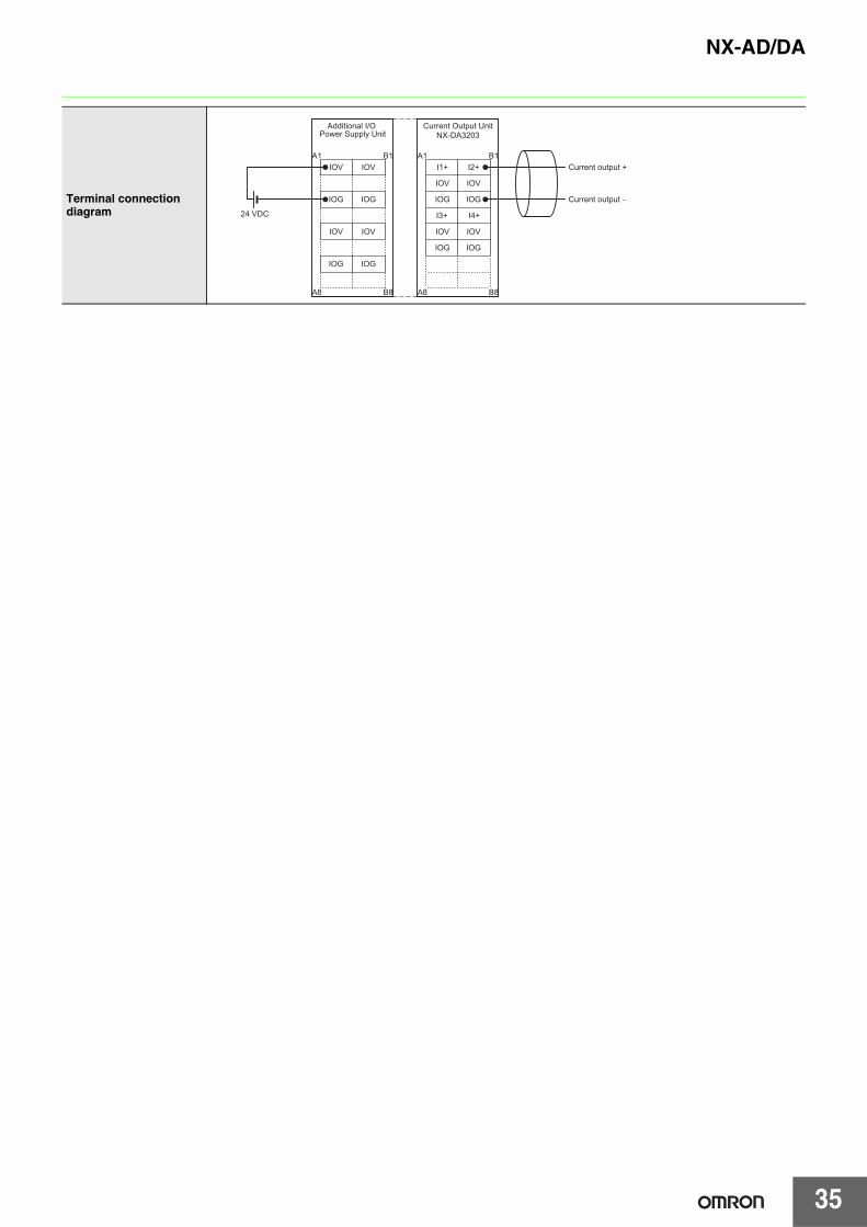
Terminal connection diagram
Current output +
Current output −
IOV
IOG
IOV
IOG
IOV
IOG
IOV
IOG
I1+
IOG
IOV
IOV
A1 B1
A8 B8
IOG
I2+
IOG
IOV
IOV
IOG
24 VDC
A1 B1
A8 B8
I3+ I4+
Additional I/O Power Supply Unit
Current Output UnitNX-DA3203
NX-AD/DA
36
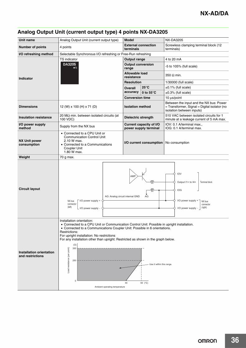
Analog Output Unit (current output type) 4 points NX-DA3205Unit name Analog Output Unit (current output type) Model NX-DA3205
Number of points 4 points External connection terminals
Screwless clamping terminal block (12 terminals)
I/O refreshing method Selectable Synchronous I/O refreshing or Free-Run refreshing
Indicator
TS indicator Output range 4 to 20 mA
Output conversion range -5 to 105% (full scale)
Allowable load resistance 350 Ω min.
Resolution 1/30000 (full scale)
Overall accuracy
25°C ±0.1% (full scale)
0 to 55°C ±0.3% (full scale)
Conversion time 10 μs/point
Dimensions 12 (W) x 100 (H) x 71 (D) Isolation methodBetween the input and the NX bus: Power = Transformer, Signal = Digital isolator (no isolation between inputs)
Insulation resistance 20 MΩ min. between isolated circuits (at 100 VDC) Dielectric strength 510 VAC between isolated circuits for 1
minute at a leakage current of 5 mA max.
I/O power supply method Supply from the NX bus Current capacity of I/O
power supply terminalIOV: 0.1 A/terminal max.,IOG: 0.1 A/terminal max.
NX Unit power consumption
• Connected to a CPU Unit or Communication Control Unit2.10 W max.
• Connected to a Communications Coupler Unit1.80 W max.
I/O current consumption No consumption
Weight 70 g max.
Circuit layout
Installation orientation and restrictions
Installation orientation:• Connected to a CPU Unit or Communication Control Unit: Possible in upright installation.• Connected to a Communications Coupler Unit: Possible in 6 orientations.
Restrictions:For upright installation: No restrictionsFor any installation other than upright: Restricted as shown in the graph below.
IOV
AG
IOG
AMP
Output I1+ to I4+
NX bus connector (left)
Terminal block
I/O power supply +
I/O power supply −
I/O power supply +
I/O power supply −
NX bus connector (right)
AG: Analog circuit internal GND
Ambient operating temperature
Use it within this range.
Load
resi
stan
ce (p
er p
oint
)
40 55
0
250
350
(°C)
(Ω)

37
NX-AD/DA
Terminal connection diagram
Current output +
Current output −
IOV
IOG
IOV
IOG
IOV
IOG
IOV
IOG
I1+
IOG
IOV
IOV
A1 B1
A8 B8
IOG
I2+
IOG
IOV
IOV
IOG
24 VDC
A1 B1
A8 B8
I3+ I4+
Additional I/O Power Supply Unit
Current Output UnitNX-DA3205
NX-AD/DA
38
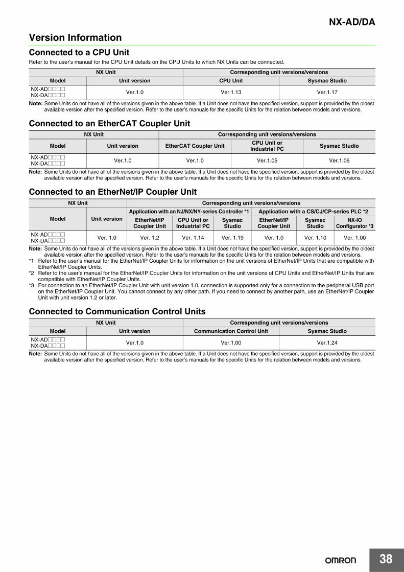
Version InformationConnected to a CPU UnitRefer to the user's manual for the CPU Unit details on the CPU Units to which NX Units can be connected.
Note: Some Units do not have all of the versions given in the above table. If a Unit does not have the specified version, support is provided by the oldest available version after the specified version. Refer to the user’s manuals for the specific Units for the relation between models and versions.
Connected to an EtherCAT Coupler Unit
Note: Some Units do not have all of the versions given in the above table. If a Unit does not have the specified version, support is provided by the oldest available version after the specified version. Refer to the user’s manuals for the specific Units for the relation between models and versions.
Connected to an EtherNet/IP Coupler Unit
Note: Some Units do not have all of the versions given in the above table. If a Unit does not have the specified version, support is provided by the oldest available version after the specified version. Refer to the user’s manuals for the specific Units for the relation between models and versions.
*1 Refer to the user’s manual for the EtherNet/IP Coupler Units for information on the unit versions of EtherNet/IP Units that are compatible with EtherNet/IP Coupler Units.
*2 Refer to the user’s manual for the EtherNet/IP Coupler Units for information on the unit versions of CPU Units and EtherNet/IP Units that are compatible with EtherNet/IP Coupler Units.
*3 For connection to an EtherNet/IP Coupler Unit with unit version 1.0, connection is supported only for a connection to the peripheral USB port on the EtherNet/IP Coupler Unit. You cannot connect by any other path. If you need to connect by another path, use an EtherNet/IP Coupler Unit with unit version 1.2 or later.
Connected to Communication Control Units
Note: Some Units do not have all of the versions given in the above table. If a Unit does not have the specified version, support is provided by the oldest available version after the specified version. Refer to the user’s manuals for the specific Units for the relation between models and versions.
NX Unit Corresponding unit versions/versionsModel Unit version CPU Unit Sysmac Studio
NX-AD@@@@NX-DA@@@@ Ver.1.0 Ver.1.13 Ver.1.17
NX Unit Corresponding unit versions/versions
Model Unit version EtherCAT Coupler Unit CPU Unit or Industrial PC Sysmac Studio
NX-AD@@@@NX-DA@@@@ Ver.1.0 Ver.1.0 Ver.1.05 Ver.1.06
NX Unit Corresponding unit versions/versions
Model Unit versionApplication with an NJ/NX/NY-series Controller *1 Application with a CS/CJ/CP-series PLC *2
EtherNet/IP Coupler Unit
CPU Unit or Industrial PC
Sysmac Studio
EtherNet/IP Coupler Unit
Sysmac Studio
NX-IO Configurator *3
NX-AD@@@@NX-DA@@@@ Ver. 1.0 Ver. 1.2 Ver. 1.14 Ver. 1.19 Ver. 1.0 Ver. 1.10 Ver. 1.00
NX Unit Corresponding unit versions/versionsModel Unit version Communication Control Unit Sysmac Studio
NX-AD@@@@NX-DA@@@@ Ver.1.0 Ver.1.00 Ver.1.24
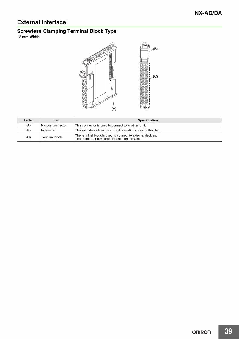
39
NX-AD/DAExternal InterfaceScrewless Clamping Terminal Block Type12 mm Width
Letter Item Specification(A) NX bus connector This connector is used to connect to another Unit.
(B) Indicators The indicators show the current operating status of the Unit.
(C) Terminal block The terminal block is used to connect to external devices.The number of terminals depends on the Unit.
(A)
(C)
(B)
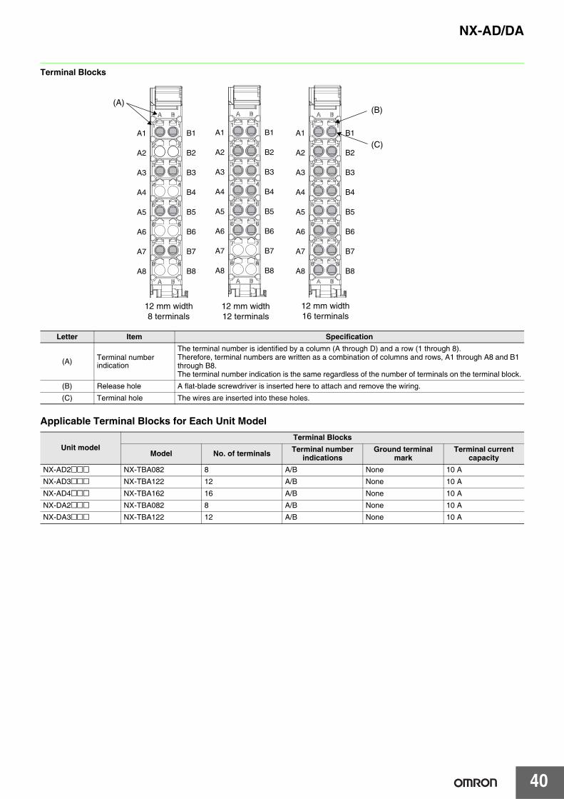
NX-AD/DA
40
Terminal Blocks
Applicable Terminal Blocks for Each Unit Model
Letter Item Specification
(A) Terminal number indication
The terminal number is identified by a column (A through D) and a row (1 through 8).Therefore, terminal numbers are written as a combination of columns and rows, A1 through A8 and B1 through B8.The terminal number indication is the same regardless of the number of terminals on the terminal block.
(B) Release hole A flat-blade screwdriver is inserted here to attach and remove the wiring.
(C) Terminal hole The wires are inserted into these holes.
Unit modelTerminal Blocks
Model No. of terminals Terminal number indications
Ground terminal mark
Terminal current capacity
NX-AD2@@@ NX-TBA082 8 A/B None 10 A
NX-AD3@@@ NX-TBA122 12 A/B None 10 A
NX-AD4@@@ NX-TBA162 16 A/B None 10 A
NX-DA2@@@ NX-TBA082 8 A/B None 10 A
NX-DA3@@@ NX-TBA122 12 A/B None 10 A
12 mm width8 terminals
(B)
12 mm width12 terminals
12 mm width16 terminals
(C)
(A)
A1
A2
A3
A4
A5
A6
A7
A8
B1
B2
B3
B4
B5
B6
B7
B8
A1
A2
A3
A4
A5
A6
A7
A8
B1
B2
B3
B4
B5
B6
B7
B8
A1
A2
A3
A4
A5
A6
A7
A8
B1
B2
B3
B4
B5
B6
B7
B8
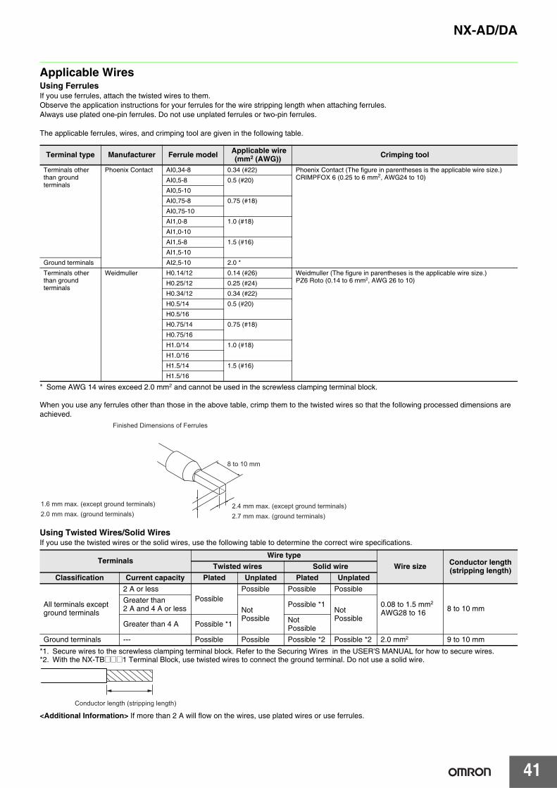
41
NX-AD/DA
Applicable WiresUsing FerrulesIf you use ferrules, attach the twisted wires to them.Observe the application instructions for your ferrules for the wire stripping length when attaching ferrules.Always use plated one-pin ferrules. Do not use unplated ferrules or two-pin ferrules.
The applicable ferrules, wires, and crimping tool are given in the following table.
* Some AWG 14 wires exceed 2.0 mm2 and cannot be used in the screwless clamping terminal block.
When you use any ferrules other than those in the above table, crimp them to the twisted wires so that the following processed dimensions are achieved.
Using Twisted Wires/Solid WiresIf you use the twisted wires or the solid wires, use the following table to determine the correct wire specifications.
*1. Secure wires to the screwless clamping terminal block. Refer to the Securing Wires in the USER'S MANUAL for how to secure wires.*2. With the NX-TB@@@1 Terminal Block, use twisted wires to connect the ground terminal. Do not use a solid wire.
<Additional Information> If more than 2 A will flow on the wires, use plated wires or use ferrules.
Terminal type Manufacturer Ferrule model Applicable wire(mm2 (AWG)) Crimping tool
Terminals other than ground terminals
Phoenix Contact AI0,34-8 0.34 (#22) Phoenix Contact (The figure in parentheses is the applicable wire size.)CRIMPFOX 6 (0.25 to 6 mm2, AWG24 to 10)AI0,5-8 0.5 (#20)
AI0,5-10
AI0,75-8 0.75 (#18)
AI0,75-10
AI1,0-8 1.0 (#18)
AI1,0-10
AI1,5-8 1.5 (#16)
AI1,5-10
Ground terminals AI2,5-10 2.0 *
Terminals other than ground terminals
Weidmuller H0.14/12 0.14 (#26) Weidmuller (The figure in parentheses is the applicable wire size.)PZ6 Roto (0.14 to 6 mm2, AWG 26 to 10)H0.25/12 0.25 (#24)
H0.34/12 0.34 (#22)
H0.5/14 0.5 (#20)
H0.5/16
H0.75/14 0.75 (#18)
H0.75/16
H1.0/14 1.0 (#18)
H1.0/16
H1.5/14 1.5 (#16)
H1.5/16
TerminalsWire type
Wire size Conductor length (stripping length)Twisted wires Solid wire
Classification Current capacity Plated Unplated Plated Unplated
All terminals except ground terminals
2 A or lessPossible
Possible Possible Possible
0.08 to 1.5 mm2
AWG28 to 16 8 to 10 mmGreater than 2 A and 4 A or less Not
Possible
Possible *1Not Possible
Greater than 4 A Possible *1 Not Possible
Ground terminals --- Possible Possible Possible *2 Possible *2 2.0 mm2 9 to 10 mm
Finished Dimensions of Ferrules
1.6 mm max. (except ground terminals)2.0 mm max. (ground terminals)
2.4 mm max. (except ground terminals)2.7 mm max. (ground terminals)
8 to 10 mm
Conductor length (stripping length)
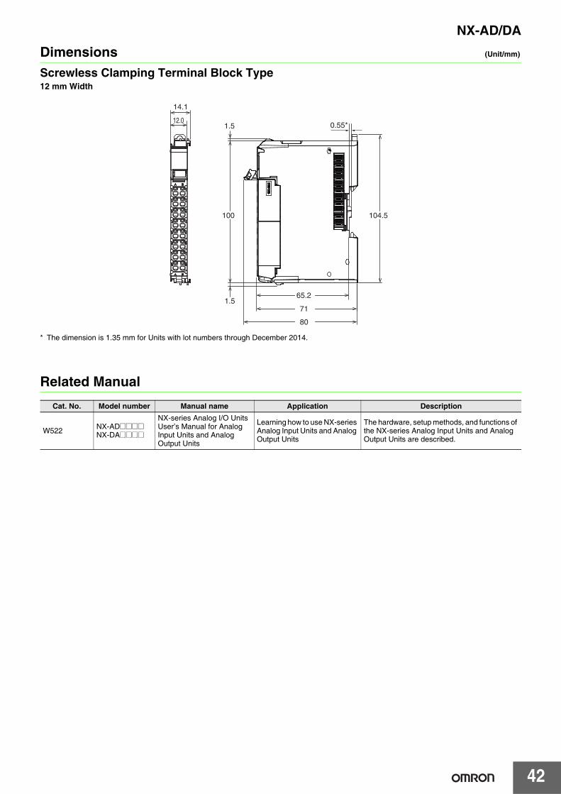
NX-AD/DA
42
Dimensions (Unit/mm)
Screwless Clamping Terminal Block Type12 mm Width
* The dimension is 1.35 mm for Units with lot numbers through December 2014.
Related ManualCat. No. Model number Manual name Application Description
W522 NX-AD@@@@NX-DA@@@@
NX-series Analog I/O Units User’s Manual for Analog Input Units and Analog Output Units
Learning how to use NX-series Analog Input Units and Analog Output Units
The hardware, setup methods, and functions of the NX-series Analog Input Units and Analog Output Units are described.
14.1
12.0
100
1.5
1.5
104.5
65.2
80
71
0.55*
Terms and Conditions Agreement Read and understand this catalog. Please read and understand this catalog before purchasing the products. Please consult your OMRON representative if you have any questions or comments. Warranties. (a) Exclusive Warranty. Omron’s exclusive warranty is that the Products will be free from defects in materials and workmanship for a period of twelve months from the date of sale by Omron (or such other period expressed in writing by Omron). Omron disclaims all other warranties, express or implied. (b) Limitations. OMRON MAKES NO WARRANTY OR REPRESENTATION, EXPRESS OR IMPLIED, ABOUT NON-INFRINGEMENT, MERCHANTABILITY OR FITNESS FOR A PARTICULAR PURPOSE OF THE PRODUCTS. BUYER ACKNOWLEDGES THAT IT ALONE HAS DETERMINED THAT THE PRODUCTS WILL SUITABLY MEET THE REQUIREMENTS OF THEIR INTENDED USE. Omron further disclaims all warranties and responsibility of any type for claims or expenses based on infringement by the Products or otherwise of any intellectual property right. (c) Buyer Remedy. Omron’s sole obligation hereunder shall be, at Omron’s election, to (i) replace (in the form originally shipped with Buyer responsible for labor charges for removal or replacement thereof) the non-complying Product, (ii) repair the non-complying Product, or (iii) repay or credit Buyer an amount equal to the purchase price of the non-complying Product; provided that in no event shall Omron be responsible for warranty, repair, indemnity or any other claims or expenses regarding the Products unless Omron’s analysis confirms that the Products were properly handled, stored, installed and maintained and not subject to contamination, abuse, misuse or inappropriate modification. Return of any Products by Buyer must be approved in writing by Omron before shipment. Omron Companies shall not be liable for the suitability or unsuitability or the results from the use of Products in combination with any electrical or electronic components, circuits, system assemblies or any other materials or substances or environments. Any advice, recommendations or information given orally or in writing, are not to be construed as an amendment or addition to the above warranty. See http://www.omron.com/global/ or contact your Omron representative for published information. Limitation on Liability; Etc. OMRON COMPANIES SHALL NOT BE LIABLE FOR SPECIAL, INDIRECT, INCIDENTAL, OR CONSEQUENTIAL DAMAGES, LOSS OF PROFITS OR PRODUCTION OR COMMERCIAL LOSS IN ANY WAY CONNECTED WITH THE PRODUCTS, WHETHER SUCH CLAIM IS BASED IN CONTRACT, WARRANTY, NEGLIGENCE OR STRICT LIABILITY. Further, in no event shall liability of Omron Companies exceed the individual price of the Product on which liability is asserted. Suitability of Use. Omron Companies shall not be responsible for conformity with any standards, codes or regulations which apply to the combination of the Product in the Buyer’s application or use of the Product. At Buyer’s request, Omron will provide applicable third party certification documents identifying ratings and limitations of use which apply to the Product. This information by itself is not sufficient for a complete determination of the suitability of the Product in combination with the end product, machine, system, or other application or use. Buyer shall be solely responsible for determining appropriateness of the particular Product with respect to Buyer’s application, product or system. Buyer shall take application responsibility in all cases. NEVER USE THE PRODUCT FOR AN APPLICATION INVOLVING SERIOUS RISK TO LIFE OR PROPERTY OR IN LARGE QUANTITIES WITHOUT ENSURING THAT THE SYSTEM AS A WHOLE HAS BEEN DESIGNED TO ADDRESS THE RISKS, AND THAT THE OMRON PRODUCT(S) IS PROPERLY RATED AND INSTALLED FOR THE INTENDED USE WITHIN THE OVERALL EQUIPMENT OR SYSTEM. Programmable Products. Omron Companies shall not be responsible for the user’s programming of a programmable Product, or any consequence thereof. Performance Data. Data presented in Omron Company websites, catalogs and other materials is provided as a guide for the user in determining suitability and does not constitute a warranty. It may represent the result of Omron’s test conditions, and the user must correlate it to actual application requirements. Actual performance is subject to the Omron’s Warranty and Limitations of Liability. Change in Specifications. Product specifications and accessories may be changed at any time based on improvements and other reasons. It is our practice to change part numbers when published ratings or features are changed, or when significant construction changes are made. However, some specifications of the Product may be changed without any notice. When in doubt, special part numbers may be assigned to fix or establish key specifications for your application. Please consult with your Omron’s representative at any time to confirm actual specifications of purchased Product. Errors and Omissions. Information presented by Omron Companies has been checked and is believed to be accurate; however, no responsibility is assumed for clerical, typographical or proofreading errors or omissions.
2018.7
In the interest of product improvement, specifications are subject to change without notice.
OMRON Corporation Industrial Automation Company http://www.ia.omron.com/
(c)Copyright OMRON Corporation 2018 All Right Reserved.