Embed Size (px)
Citation preview

CSPADs: how to operate them, which performance to expect and what kind of features are available
Gabriella Carini, Gabriel Blaj, Philip Hart, Sven Herrmann

Cornell-SLAC Pixel Array Detector
2
• What is it? An integrating pixel array detector with readout speed of 120 frames per second. • Why is it different from Pilatus? Pilatus is a counting pixel array detector: if your photons arrive all at once (like at LCLS) it will always count 1. • What does it mean v1.0, v1.2, v1.5 & v1.6? They do represent different upgrades of the detector with corresponding improved performance. • What does it mean 140k? And 2.3M? They are the number of pixels per camera. • What do I need to know to use it? Very little – details and settings should be discussed with the point-of-contact (POC). • What can I learn about it? As much as you like!

IN
reset
gain
S&H
read EN
Vref
ramp
counter data bus
fire logic
comparator reset
ADC clk
HV bias
Cornell-SLAC Pixel Array Detector
Koerner L J, Philipp H T, Hromalik M S, Tate M W, and Gruner S M 2009 JINST 4 P03001 Philipp H T et al. 2010 IEEE Trans Nucl Sci 57 3795 Philipp H et al. 2011 Nucl Instr Meth Phys Res A 649 67 Hart P A et al. 2012 Proc SPIE 8504 85040C Hart P A et al. 2012 IEEE NSS MIC Conference 538 Herrmann S C et al. 2013 Nucl Instr Meth Phys Res A 718 550 Herrmann S C et al. 2012 IEEE NSS MIC Conference 520 Herrmann S C et al. submitted to JPCS (SRI 2013)
Schematic of a CSPAD pixel
3

IN
reset
gain
S&H
read EN
Vref
ramp
counter data bus
fire logic
comparator reset
ADC clk
HV bias
Cornell-SLAC Pixel Array Detector
Koerner L J, Philipp H T, Hromalik M S, Tate M W, and Gruner S M 2009 JINST 4 P03001 Philipp H T et al. 2010 IEEE Trans Nucl Sci 57 3795 Philipp H et al. 2011 Nucl Instr Meth Phys Res A 649 67 Hart P A et al. 2012 Proc SPIE 8504 85040C Hart P A et al. 2012 IEEE NSS MIC Conference 538 Herrmann S C et al. 2013 Nucl Instr Meth Phys Res A 718 550 Herrmann S C et al. 2012 IEEE NSS MIC Conference 520 Herrmann S C et al. submitted to JPCS (SRI 2013)
Schematic of a CSPAD pixel
4
Technical papers!!!

IN
reset
gain
S&H
read EN
Vref
ramp
counter data bus
fire logic
comparator reset
ADC clk
HV bias
Cornell-SLAC Pixel Array Detector
Koerner L J, Philipp H T, Hromalik M S, Tate M W, and Gruner S M 2009 JINST 4 P03001 Philipp H T et al. 2010 IEEE Trans Nucl Sci 57 3795 Philipp H et al. 2011 Nucl Instr Meth Phys Res A 649 67 Hart P A et al. 2012 Proc SPIE 8504 85040C Hart P A et al. 2012 IEEE NSS MIC Conference 538 Herrmann S C et al. 2013 Nucl Instr Meth Phys Res A 718 550 Herrmann S C et al. 2012 IEEE NSS MIC Conference 520 Herrmann S C et al. submitted to JPCS (SRI 2013)
Schematic of a CSPAD pixel
5
Technical papers!!!
CSPAD properties Pixel size Chip area Maximum signal Frame rate Noise
110 µm x 110 µm 185 x 194 pixels per ASIC (full reticle size) 2700 8keV photons/pixel (low gain) 350 8keV photons/pixel (high gain) 120Hz ~ 3.5 keV (low gain), ~ 1 keV (high gain)

CSPAD cameras assembly
• 2 ASICs • 110um pixel size • 185 x 388 pixels/sensor • rigid-flex PCB holds 2 ASICs • 2 PCBs holding 4 ASICs are
glued on an aluminum carrier • 2 flex leads connect to the support
electronics
6 Detail of CSPAD 2.3Mpixel camera
CSPAD: basic module assembly

CSPAD cameras history
CSPAD V1.0 CSPAD V1.2 CSPAD V1.5 & V1.6
2012/13 2013/14
ePIX10k
• XPP • CXI
• XPP • CXI
• XPP • CXI
2010/11 • MEC • XCS
• MEC • XCS
Used at LCLS: • CXI, XPP, XCS, MEC: during the first 4 years of operation has
become the workhorse of the LCLS detectors
• It has been implemented in several versions and cameras with different area and shape • 2.3Mpixel and 140kpixel cameras • Vacuum compatibles
Used at SACLA, SSRL and APS
7
CSPAD-140k

8
Some improvements – from v1.0 to v1.2, v1.5 and v1.6
0
200
400
600
800
1000
1200
1400
1600
1800
2000
0 200 400 600 800 1000
CSPA
D am
plitu
de / pixel [A
DU]
integration time [us]
V1.0
V1.2
V1.5
Thermo-mechanical Electronics Firmware
ASIC Electronics Firmware
Electronics Firmware
V1.6
V1.0
V1.2
Linearity at high gain Measurements performed at SSRL BL 2-2
V1.5
relative noise
Detector for our users facilities… … and our user facilities for detector development
• Active proposal for beamtime at SSRL • Important to complement first characterizations with x-
ray tube
CSPAD 2.3M v1.0 and mobile DAQ at SSRL BL 2-2
CSPAD 140k v1.5: energy scans. Measurements at room temperature. Histograms of all pixels with pedestal and common mode correction (no per-pixel correction)
a)
b)
Linearity measurements with the CSPAD-140k v1.2 at BL 2-2. Improved electronics resulted in good linearity both at high (a) and low gain (b).
9
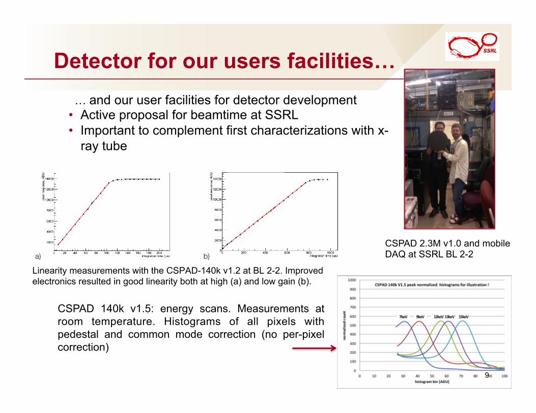
LCLS: different working conditions
In red: intensity distribution measured with the gas detector. In black: intensity distribution downstream the monochromator measured with a PIPS diode (Canberra Inc.) and in-house developed readout electronics.
Correlation plots: CSPAD vs beam monitor. After optimization of the in-house electronics used to measure beam position and intensity.
Beam instability: required improved diagnostics*
*Herrmann S C et al. submitted to JPCS (SRI 2013) 10

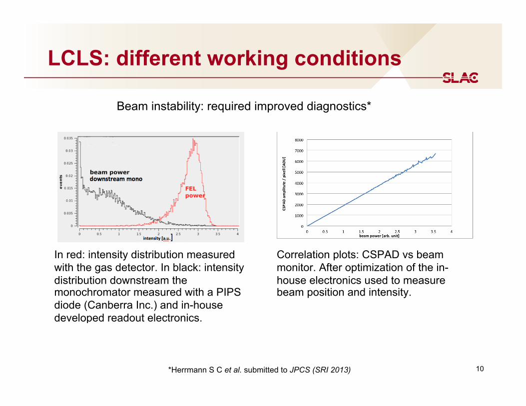
Non-linearity effect at high fluence
11
MEC – CSPAD 140k V1.0 Bismuth high pressure phase transitions – PI M. McMahon
Courtesy of Hae-Ja Lee, Philip Heinman
Non-linearity effect at high fluence
a) b) c)
Linearity response of the CSPAD in low gain. a) Standard setting. b) Different reference voltages at the preamplifier. The flat-top of the response is generated by the ADCs. c) Different sensor bias voltages.
a) b) c)
Simulation of the response of the CSPAD to increasing charge at the input. a) 10ns charge collection time; b) 100ns charge collection time; 200ns charge collection time.
12 G. A. Carini et al. submitted to JPCS (SRI 2013)

13
Starting up

14
Important to remember
Integrating Pixel Array Detectors need: • Dark correction • Frame common mode correction • Mask bad pixels • Gain calibration • Cross talk correction • Geometry reconstruction Moving towards integration of all the above in online and offline AMI and data analysis (see data workshop). In the future we will provide raw data and corrected data.

15
Typical examples for optical CCD - astronomy
http://starizona.com
Dark frame
Bias frame
Flat field

16
Typical examples for optical CCD - astronomy
http://starizona.com
An uncalibrated image of M51, the Whirlpool Galaxy (“raw data”).
A calibrated and enhanced version of the M51 image.

17
Dark correction…
…What is it? In general it is a frame without illumination, hence dark. Its signal will have many contributions (i.e. leakage current) that averaged can be ‘corrected’.

18
Frame common mode correction…
uncorrected: 5.6 r.m.s corrected: 4.4 r.m.s.

19
Mask bad pixels…

20
Gain calibration…
…What is it? Is it always needed?
Two adjacent pixels: V1.5
Two adjacent pixels: V1.6
Two adjacent pixels (only singles): V1.5
Two adjacent pixels (only singles): V1.6
Extreme case: pixels were randomly chosen to show a significant gain difference
Blue = 58 Red = 76
Blue = 68 Red = 72
Blue = 56 Red = 75 34%
Blue = 67 Red = 71 5%

21
Cross talk correction…
Cross-talk seen with correlation plots: Intensity measured with the CSPAD vs intensity measured with the beam monitor. On the left vertical axis the values of the baseline shift of a shielded area when an adjacent area is illuminated with strong signal (right vertical axis).
V1.5

22
Geometry reconstruction
Silver behenate rings: before (left) and after (right) reconstruction. Single event image.
23
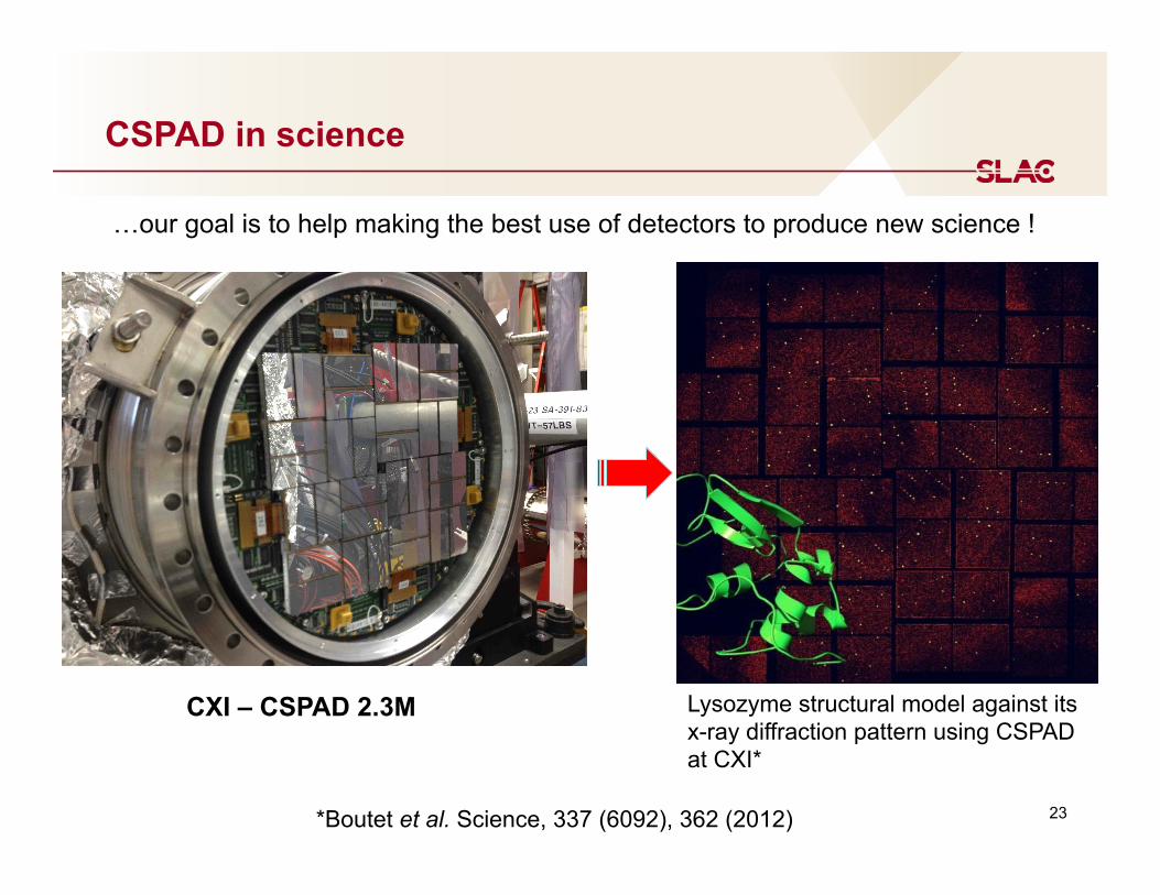
CSPAD in science
…our goal is to help making the best use of detectors to produce new science !
CXI – CSPAD 2.3M Lysozyme structural model against its x-ray diffraction pattern using CSPAD at CXI*
*Boutet et al. Science, 337 (6092), 362 (2012)
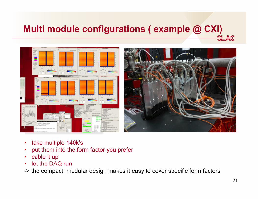
Multi module configurations ( example @ CXI)
• take multiple 140k’s • put them into the form factor you prefer • cable it up • let the DAQ run -> the compact, modular design makes it easy to cover specific form factors
24
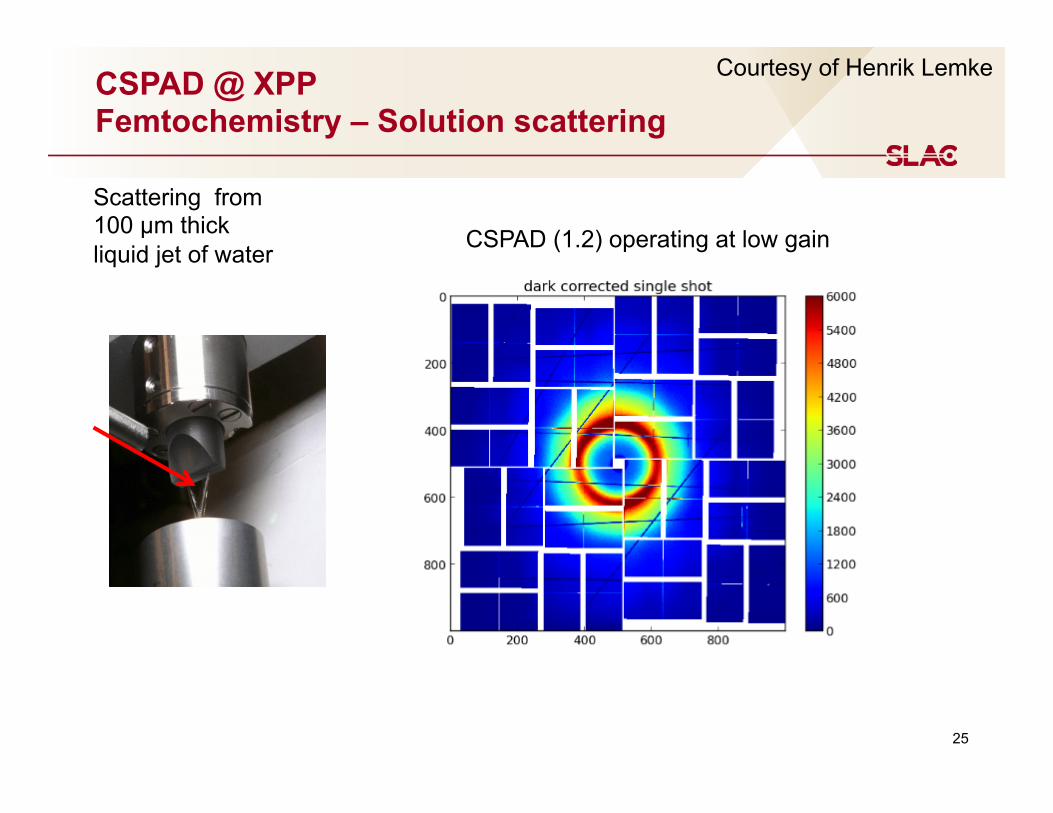
CSPAD @ XPP Femtochemistry – Solution scattering
Scattering from 100 µm thick liquid jet of water
25
CSPAD (1.2) operating at low gain
Courtesy of Henrik Lemke

26
Gain nonlinearity and ASIC artifacts
Measured signal is function of intensity, because of varying gain. --> Pump probe: relative changes for intensity filtered pulse ensemble Remaining artifacts by e.g. noisy pixels have to be filtered as they are of similar size as the pump/probe signal.

Acoustic nanoscale resonances in InAs nanowires, SRI 2012, [email protected]
27
CSPAD area detector 120 Hz readout
Diffraction from nanowires
Bragg diffraction from nanowires, grown epitaxially from a substrate CSPAD 2.3M v1.2, high gain
28
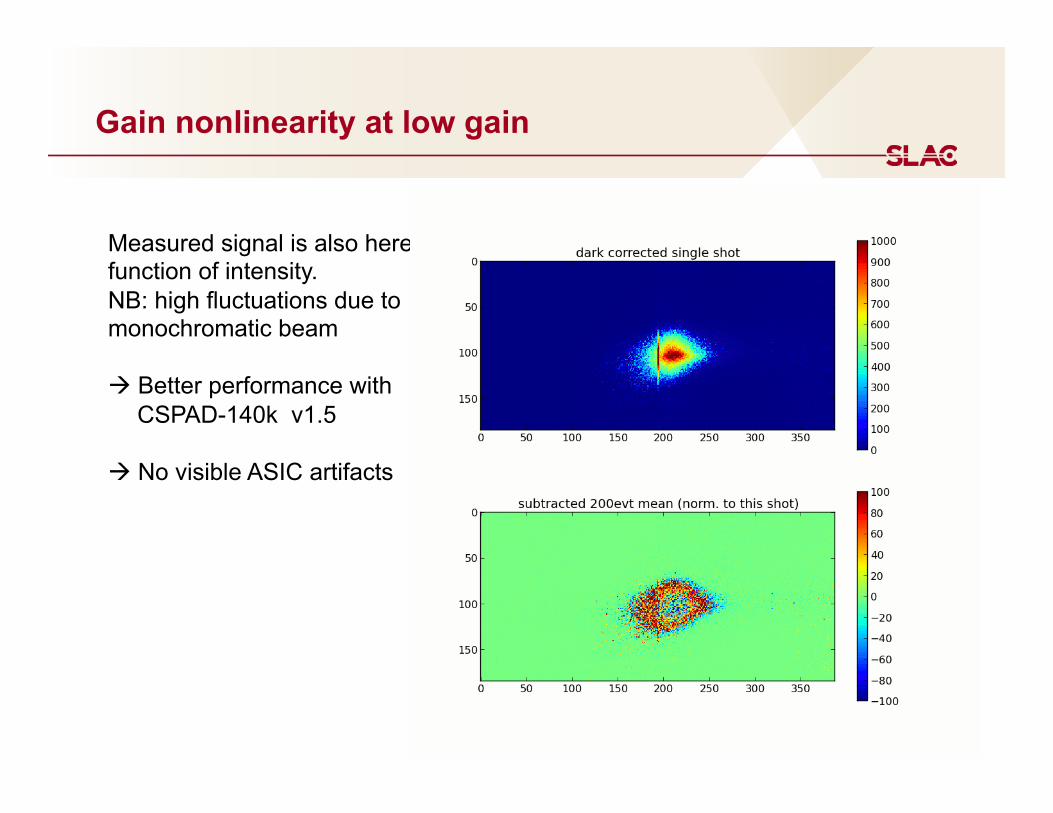
Gain nonlinearity at low gain
Measured signal is also here function of intensity. NB: high fluctuations due to monochromatic beam à Better performance with
CSPAD-140k v1.5
à No visible ASIC artifacts
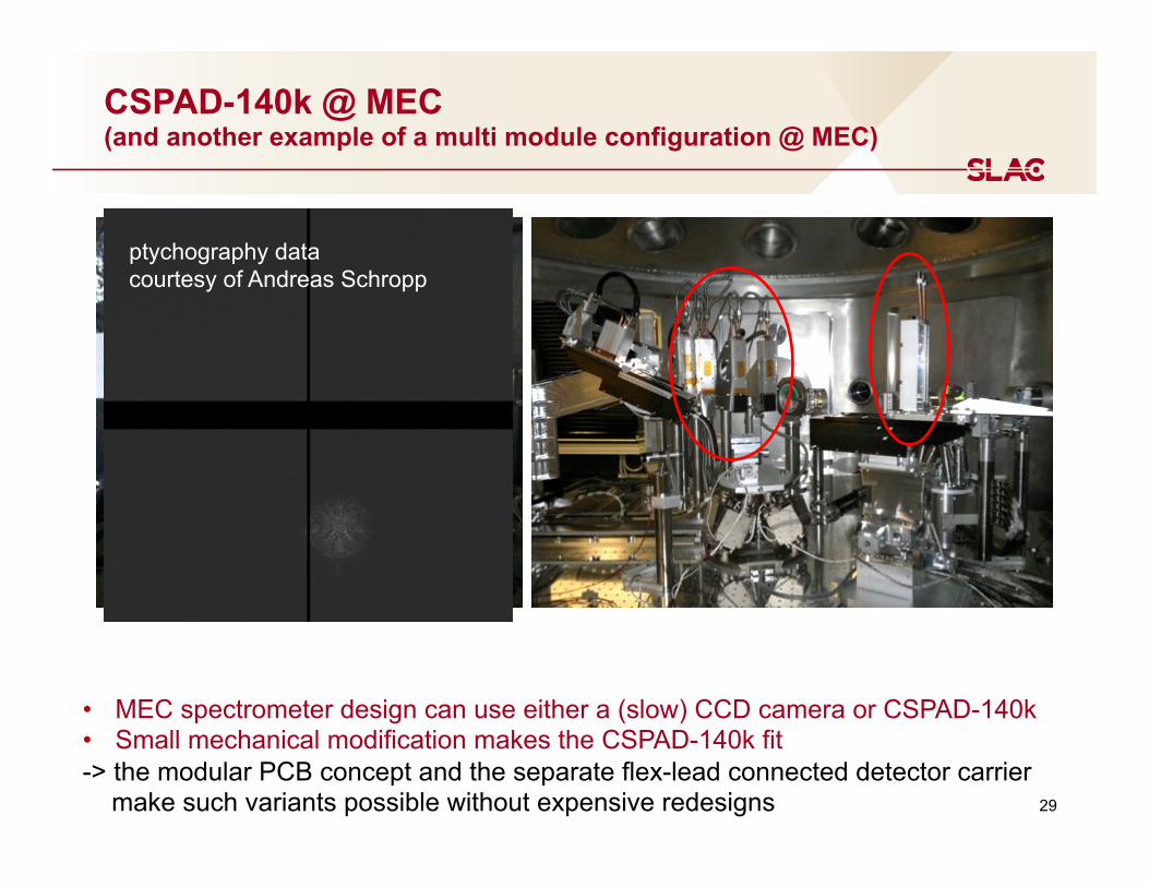
CSPAD-140k @ MEC (and another example of a multi module configuration @ MEC)
• MEC spectrometer design can use either a (slow) CCD camera or CSPAD-140k • Small mechanical modification makes the CSPAD-140k fit -> the modular PCB concept and the separate flex-lead connected detector carrier make such variants possible without expensive redesigns
ptychography data courtesy of Andreas Schropp
29

CSPAD-140k @ SSRL (preparation of XPP experiments)
-> helped to prepare an XPP experiment with beamtime at SSRL (spectrometer alignment and pre-studies of samples)
30 Used also for experiments at APS and SACLA


![W E L C O M E []...2. Offer children comfort with a hug and gentle words, help them, play with them 3. Help them understand the world around them and know what to expect. This gives](https://img.pdfslide.net/doc/110x75/5fb72e2de4c089411a2f96ee/w-e-l-c-o-m-e-2-offer-children-comfort-with-a-hug-and-gentle-words-help.jpg)


![Functional description - Particle · [4] Technically these pins are 5.0V tolerant, but since you wouldn't operate them with a 5.0V transceiver it's proper to classify them as 3.3V](https://img.pdfslide.net/doc/110x75/5fe4a5426b0509197d17ff6d/functional-description-particle-4-technically-these-pins-are-50v-tolerant.jpg)