Embed Size (px)
Citation preview

CSR101x Hardware Design Guidelines
July 2016
CSR101x is a product of Qualcomm Technologies International, Ltd
2
Hardware design• Hardware design guidelines• Bringing up the new board
Production line test
Bluetooth qualification process
Agenda
Hardware design guidelines
4
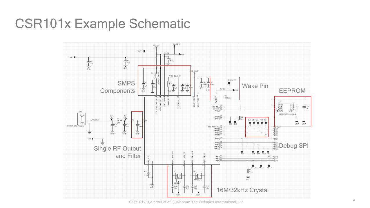
CSR101x Example Schematic
16M/32kHz Crystal
SMPS
Components
Single RF Output
and Filter
Wake Pin
Debug SPI
EEPROM
CSR101x is a product of Qualcomm Technologies International, Ltd
5
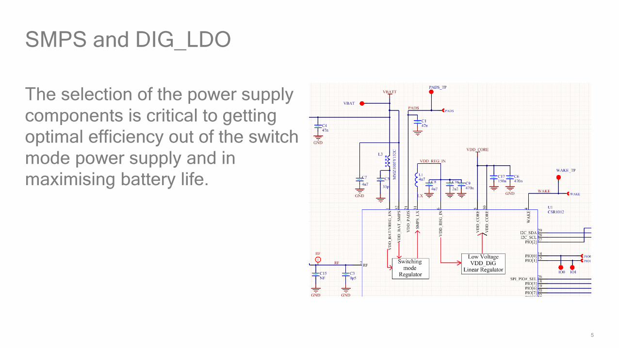
SMPS and DIG_LDO
The selection of the power supply
components is critical to getting
optimal efficiency out of the switch
mode power supply and in
maximising battery life.

6
CSR1010 (4V3) SMPS Layout Routing
C7 and C8 need an individual
ground via separate from other
grounds on top-layer (component
side)
C19 and C9 near VDD_REG_IN
CSR101x is a product of Qualcomm Technologies International, Ltd

7
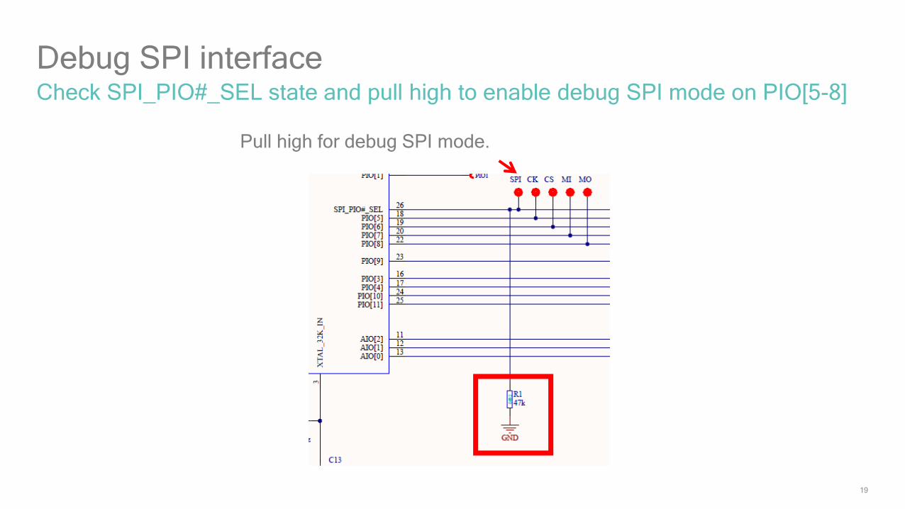
SPI_PIO#_SEL
Insert a 47kΩ pull-down resistor
on SPI_PIO#_SEL if PIO is
selected. Please don’t leave the
port open even in PIO mode
Add the VCC on SPI_PIO#_SEL
to enable debug SPI mode on
PIO[5..8]

8
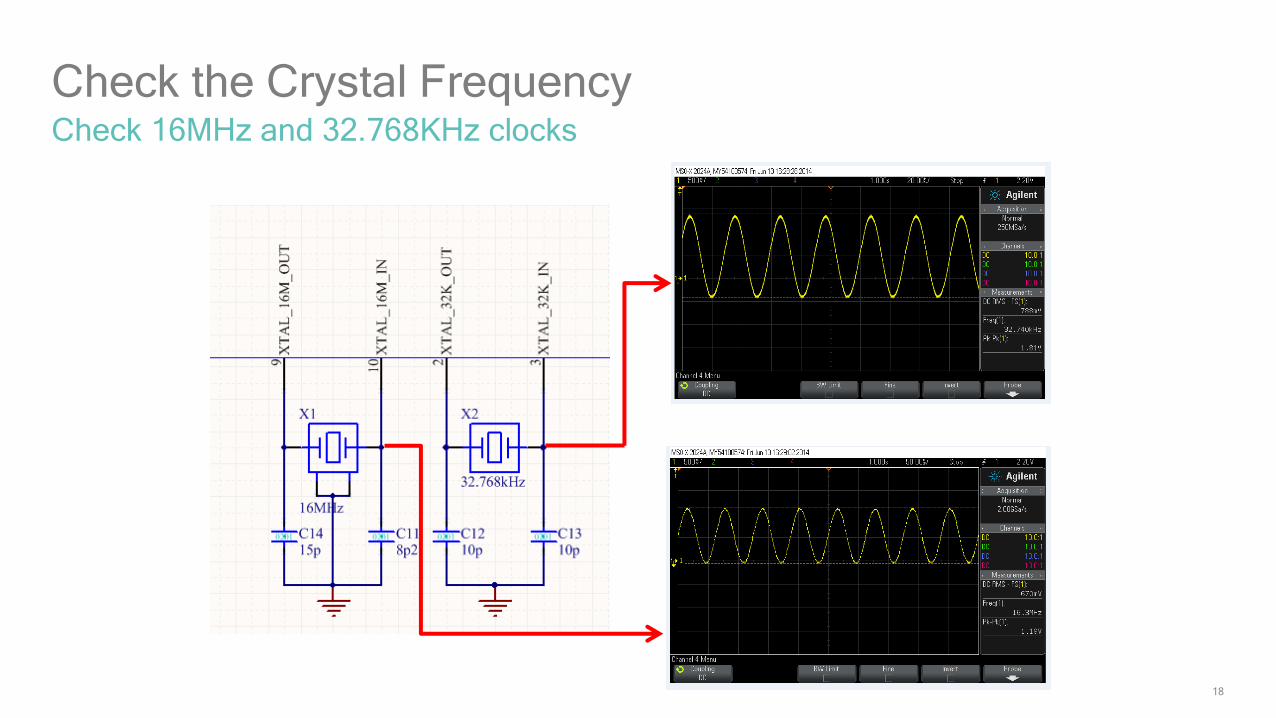
The values of 16MHz XTAL tank capacitors are in the ratio 2:1 (recommended 15pF:6.8pF). Have
the smaller capacitor on XTAL_IN
Crystal circuit
9
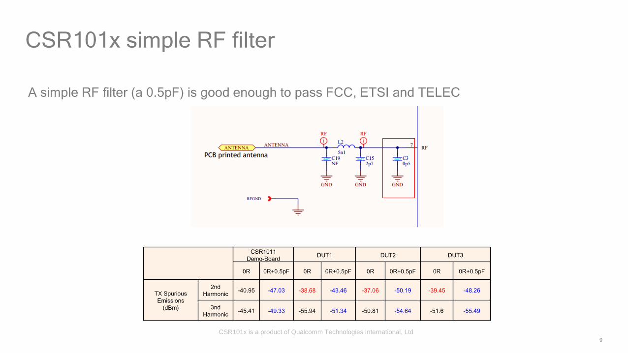
A simple RF filter (a 0.5pF) is good enough to pass FCC, ETSI and TELEC
CSR101x simple RF filter
CSR1011
Demo-BoardDUT1 DUT2 DUT3
0R 0R+0.5pF 0R 0R+0.5pF 0R 0R+0.5pF 0R 0R+0.5pF
TX Spurious
Emissions
(dBm)
2nd
Harmonic-40.95 -47.03 -38.68 -43.46 -37.06 -50.19 -39.45 -48.26
3nd
Harmonic-45.41 -49.33 -55.94 -51.34 -50.81 -54.64 -51.6 -55.49
CSR101x is a product of Qualcomm Technologies International, Ltd
10
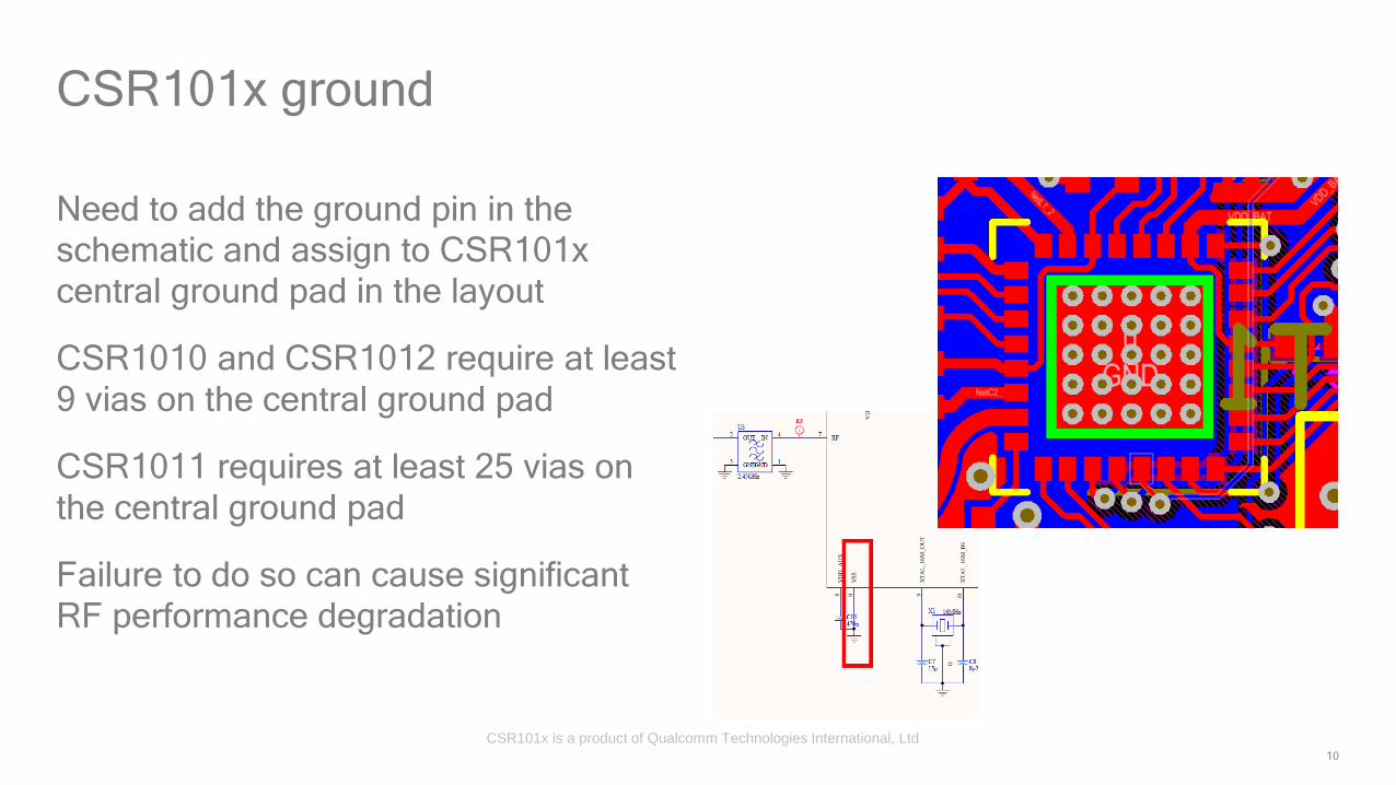
CSR101x ground
Need to add the ground pin in the
schematic and assign to CSR101x
central ground pad in the layout
CSR1010 and CSR1012 require at least
9 vias on the central ground pad
CSR1011 requires at least 25 vias on
the central ground pad
Failure to do so can cause significant
RF performance degradation
CSR101x is a product of Qualcomm Technologies International, Ltd
11
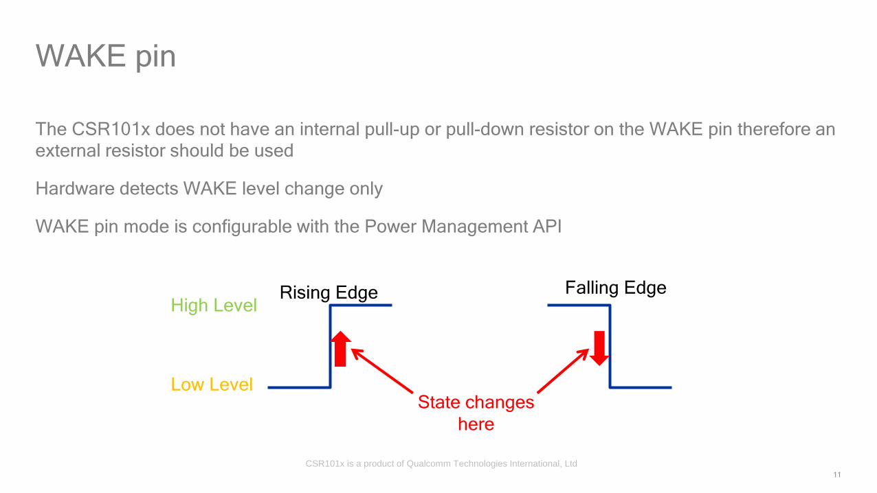
The CSR101x does not have an internal pull-up or pull-down resistor on the WAKE pin therefore an
external resistor should be used
Hardware detects WAKE level change only
WAKE pin mode is configurable with the Power Management API
WAKE pin
Rising Edge Falling EdgeHigh Level
Low LevelState changes
here
CSR101x is a product of Qualcomm Technologies International, Ltd
12
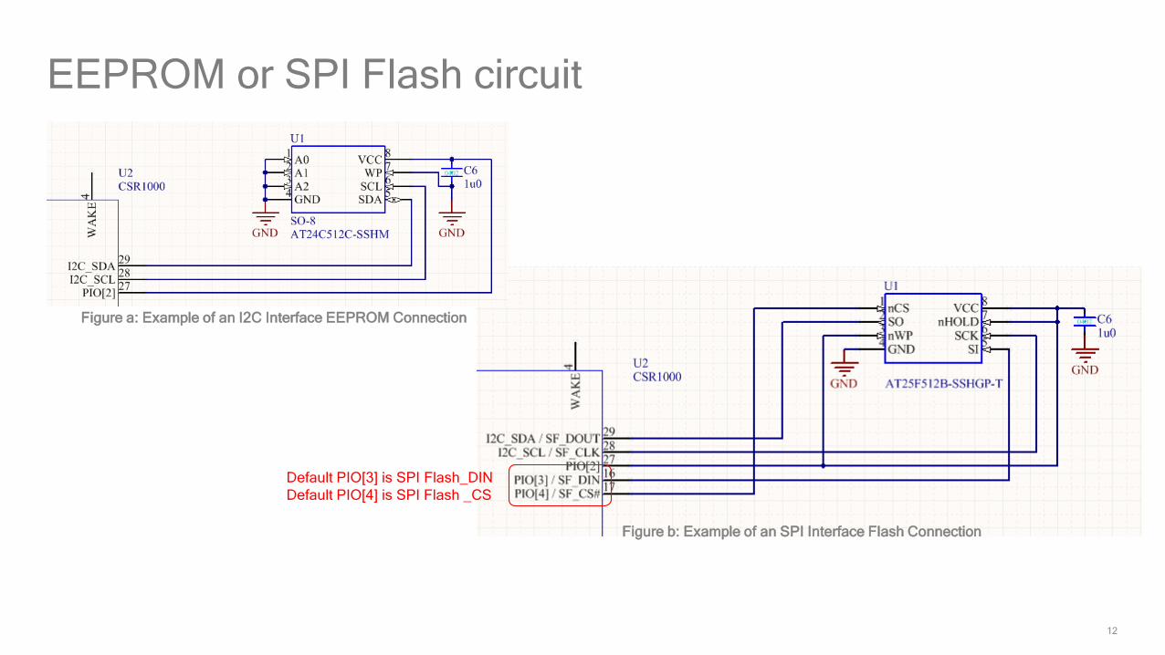
EEPROM or SPI Flash circuit
Figure a: Example of an I2C Interface EEPROM Connection
Figure b: Example of an SPI Interface Flash Connection
Default PIO[3] is SPI Flash_DIN
Default PIO[4] is SPI Flash _CS

13
There is a review template for each component
Regularly updated to add additional test cases
Comprehensive step-by-step schematic and layout guidelines
Recommended reading before embarking on a new schematic/layout design
When QTIL provide design reviews, they are usually in the form of a completed
review template
CSR Support account required - acquired with project registration or activation
Hardware Review
14
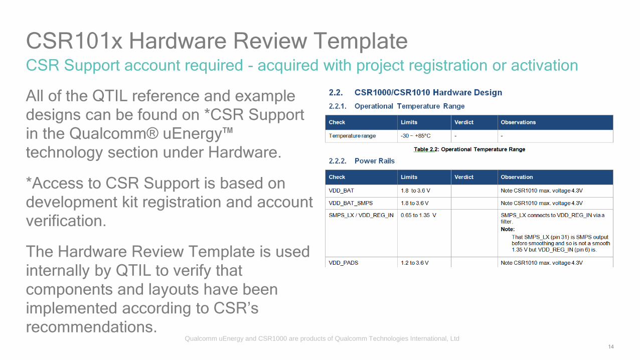
CSR101x Hardware Review Template
All of the QTIL reference and example
designs can be found on *CSR Support
in the Qualcomm® uEnergy™
technology section under Hardware.
*Access to CSR Support is based on
development kit registration and account
verification.
The Hardware Review Template is used
internally by QTIL to verify that
components and layouts have been
implemented according to CSR’s
recommendations.
CSR Support account required - acquired with project registration or activation
Qualcomm uEnergy and CSR1000 are products of Qualcomm Technologies International, Ltd

Bringing up a new board
16
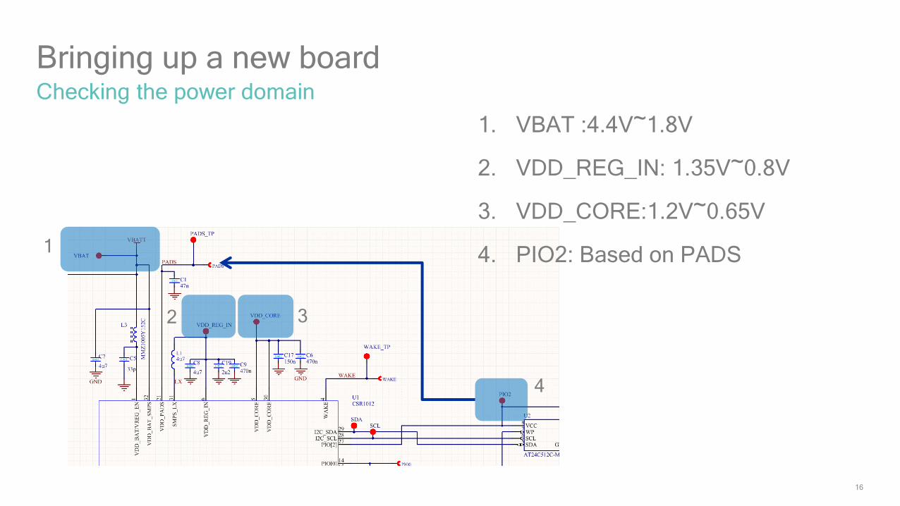
Bringing up a new boardChecking the power domain
1
2 3
4
1. VBAT :4.4V~1.8V
2. VDD_REG_IN: 1.35V~0.8V
3. VDD_CORE:1.2V~0.65V
4. PIO2: Based on PADS

17
Power Domain
If VDD_CORE and PIO2
don’t show the correct
voltage, check that the
32.768KHz clock is
running
18
Check 16MHz and 32.768KHz clocks
Check the Crystal Frequency
19
Check SPI_PIO#_SEL state and pull high to enable debug SPI mode on PIO[5-8]
Debug SPI interface
Pull high for debug SPI mode.

Production Line Test

21
Qualcomm® µEnergy™ Boards
Development Boards• CSR1011
• DB-CSR1011-10139-1A
• DK-CSR1011-10138-1A (kit)
• CSR1010• DB-CSR1010-10137-1A
• DK-CSR1010-10136-1A (kit)
USB-SPI Interface Board• Included with the development kits• Also available separately
• Part number: DK-CSR1000-10086-1A
CSR101x is a product of Qualcomm Technologies International, Ltd
22
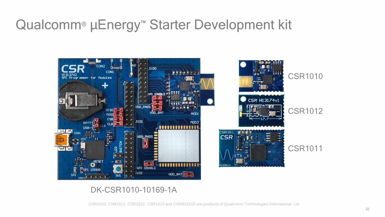
Qualcomm® µEnergy™ Starter Development kit
CSR1010
CSR1012
CSR1011
DK-CSR1010-10169-1A
CSR1010, CSR1011, CSR1012, CSR1013 and CSRB31010 are products of Qualcomm Technologies International, Ltd
23
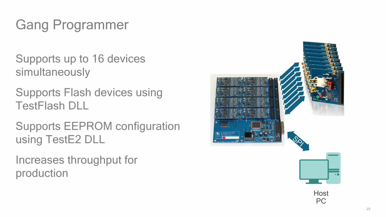
Gang Programmer
Supports up to 16 devices
simultaneously
Supports Flash devices using
TestFlash DLL
Supports EEPROM configuration
using TestE2 DLL
Increases throughput for
production
HostPC

24
Multi-way USB using USB hub
US
B
USB
HostPC
USB Hub
SP
I
US
BS
PI
US
BS
PI
US
BS
PI
US
BS
PI
US
BS
PI
US
BS
PI
US
BS
PI

25
Development Board• Part Number: DK-USB-SPI-10225-1A • Price: USD $15• Description: USB to Debug SPI• Available now via all QTIL distributors
Low cost programmer board
26
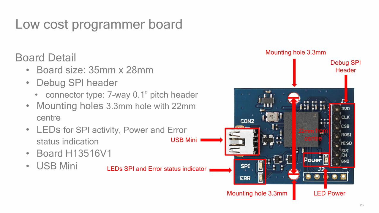
Low cost programmer board
Board Detail• Board size: 35mm x 28mm
• Debug SPI header
• connector type: 7-way 0.1” pitch header
• Mounting holes 3.3mm hole with 22mm
centre
• LEDs for SPI activity, Power and Error
status indication
• Board H13516V1
• USB Mini
USB Mini
LEDs SPI and Error status indicator
LED Power
Mounting hole 3.3mm
Mounting hole 3.3mm
Debug SPI
Header
22mm from
centre
27
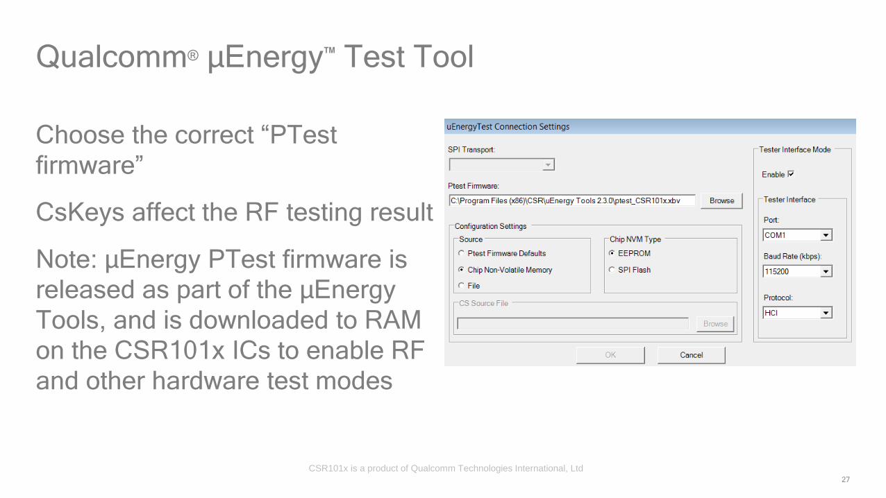
Qualcomm® µEnergy™ Test Tool
Choose the correct “PTest
firmware”
CsKeys affect the RF testing result
Note: µEnergy PTest firmware is
released as part of the µEnergy
Tools, and is downloaded to RAM
on the CSR101x ICs to enable RF
and other hardware test modes
CSR101x is a product of Qualcomm Technologies International, Ltd
28
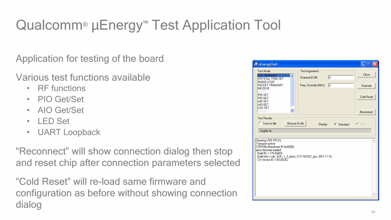
Qualcomm® µEnergy™ Test Application Tool
Application for testing of the board
Various test functions available• RF functions
• PIO Get/Set
• AIO Get/Set
• LED Set
• UART Loopback
“Reconnect” will show connection dialog then stop
and reset chip after connection parameters selected
“Cold Reset” will re-load same firmware and
configuration as before without showing connection
dialog
29
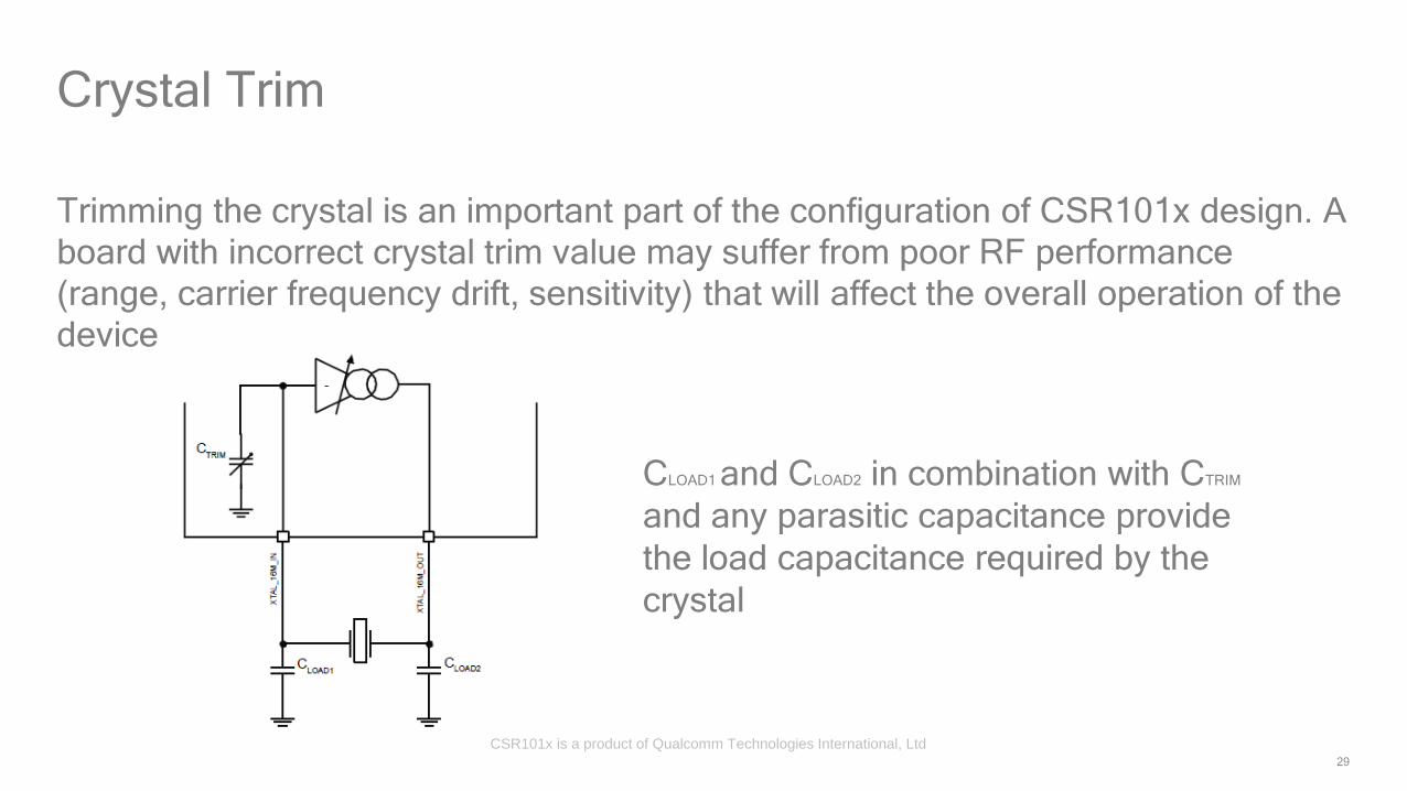
Trimming the crystal is an important part of the configuration of CSR101x design. A
board with incorrect crystal trim value may suffer from poor RF performance
(range, carrier frequency drift, sensitivity) that will affect the overall operation of the
device
Crystal Trim
CLOAD1 and CLOAD2 in combination with CTRIM
and any parasitic capacitance provide
the load capacitance required by the
crystal
CSR101x is a product of Qualcomm Technologies International, Ltd
30
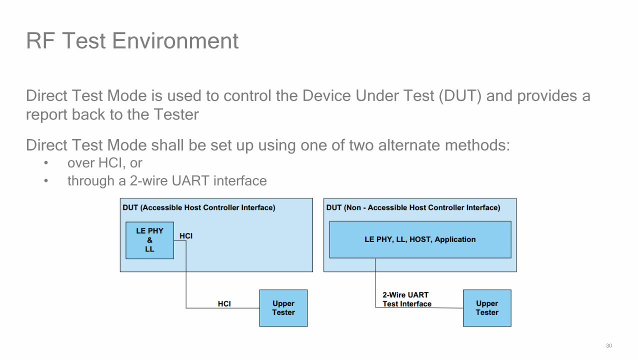
Direct Test Mode is used to control the Device Under Test (DUT) and provides a
report back to the Tester
Direct Test Mode shall be set up using one of two alternate methods:• over HCI, or
• through a 2-wire UART interface
RF Test Environment

31
Direct test mode
The unit under test needs the direct
test mode firmware to be loaded
into it or for the same API calls to
be built into the customer
application
To use a direct test, UART TX/RX
test points are required on the PCB
An example Direct Test Mode
application project is available as
an example app within the SDKUse DC power supply instead of battery during the tests

32
QTILTester Interface
Debug SPI could be also used for
RF testing – for designs that lack
spare PIOs or test points for
UART interface
Use power supply instead of battery during the tests
Qualification for Bluetooth 4.1

34
Bluetooth 4.1 improves usability for consumers, empowers innovation
for product developers and extends the technology’s foundation as an
essential link for the Internet of Things
The qualification process remains the same for all Bluetooth
specifications
Core Specification versions 2.0+EDR, 2.1+EDR, 3.0+HS and 4.0 are
still available for use and qualification
Qualification for Bluetooth 4.1

35
Qualification for Bluetooth 4.1
NOC• Normal Operating Condition
EOC• Extreme Operating Condition
Note:
Test cases in red require
complex or expensive
resources and are often
omitted for pre-production
line testing
SIG RF LE Test Cases
Test Case/Parameter Temperature Power Supply
TRM-LE/CA/01/C (Output power at NOC ) Nominal Nominal
TRM-LE/CA/02/C (Output power at EOC ) Max/Min Max/Min
TRM-LE/CA/03/C (In-band emissions at NOC) Nominal Nominal
TRM-LE/CA/04/C (In-band emissions at EOC) Max/Min Max/Min
TRM-LE/CA/05/C (Modulation characteristics) Nominal Nominal
TRM-LE/CA/06/C (Carrier frequency offset and drift at NOC) Nominal Nominal
TRM-LE/CA/07/C (Carrier frequency offset and drift at EOC) Max/Min Max/Min
RCV-LE/.CA/01/C (receiver sensitivity at NOC) Nominal Nominal
RCV-LE/.CA/02/C (receiver sensitivity at EOC) Max/Min Max/Min
RCV-LE/CA/0A/C (C/I- and selectivity performance) Nominal Nominal
RCV-LE/CA/04/C (Blocking performance) Nominal Nominal
RCV-LE/CA/05/C (Intermodulation performance) Nominal Nominal
RCV-LE/CA/06/C (Maximum input signal level) Nominal Nominal
RCV-LE/CA/07/C (PER Report Integrity) Nominal Nominal

36
Discontinuing the QDID fee
Listing fee - US $8000 or US $4000 depending on membership level• Prices correct as at end of 2015; subject to change without prior notice
• https://www.bluetooth.com/develop-with-bluetooth/qualification-listing/qualification-listing-fees
Issuing a Declaration ID as your proof of purchase• The Declaration ID is a unique identification number assigned to a listing and used as a
reference for the member’s Declaration of Compliance
Simple Listing Process• Create Qualification Project (new designs)
• Pay listing fee
• Reference a qualified design (QDID)
• List associated product(s)
New listing process from February 2014
*
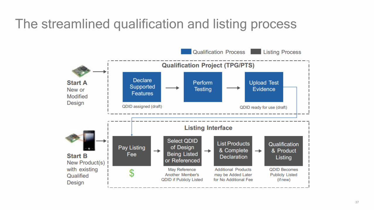
37
The streamlined qualification and listing process

Thank you
Follow us on:
For more information, visit us at:
www.qualcomm.com & www.qualcomm.com/blog
Nothing in these materials is an offer to sell any of the components or devices referenced herein.
©2016 Qualcomm Technologies, Inc. and/or its affiliated companies. All Rights Reserved.
Qualcomm is a trademark of Qualcomm Incorporated, registered in the United States and other countries. Other products and brand names may be trademarks or registered trademarks of their respective owners.
References in this presentation to “Qualcomm” may mean Qualcomm Incorporated, Qualcomm Technologies, Inc., and/or other subsidiaries or business units within the Qualcomm corporate structure, as applicable. Qualcomm Incorporated includes Qualcomm’s licensing business, QTL, and the vast majority of its patent portfolio. Qualcomm Technologies, Inc., a wholly-owned subsidiary of Qualcomm Incorporated, operates, along with its subsidiaries, substantially all of Qualcomm’s engineering, research and development functions, and substantially all of its product and services businesses, including its semiconductor business, QCT.