Embed Size (px)
Citation preview

SECTION 100 DESCRIPTION & SPECIFICATIONS
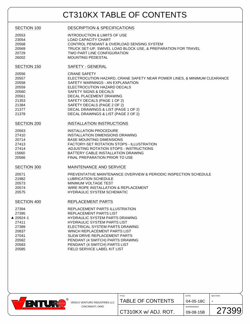
20553 INTRODUCTION & LIMITS OF USE23054 LOAD CAPACITY CHART20568 CONTROL PENDANT & OVERLOAD SENSING SYSTEM20569 TRUCK SET-UP, SWIVEL LOAD BLOCK USE, & PREPARATION FOR TRAVEL20729 TWO PART LINE CONFIGURATION26002 MOUNTING PEDESTAL
SECTION 150 SAFETY - GENERAL
20556 CRANE SAFETY20557 ELECTROCUTION HAZARD, CRANE SAFETY NEAR POWER LINES, & MINIMUM CLEARANCE20558 SAFETY WARNINGS - AN EXPLANATION20559 ELECTROCUTION HAZARD DECALS20560 SAFETY SIGNS & DECALS20561 DECAL PLACEMENT DRAWING21353 SAFETY DECALS (PAGE 1 OF 2)21384 SAFETY DECALS (PAGE 2 OF 2)21377 DECAL DRAWINGS & LIST (PAGE 1 OF 2)21378 DECAL DRAWINGS & LIST (PAGE 2 OF 2)
SECTION 200 INSTALLATION INSTRUCTIONS
20563 INSTALLATION PROCEDURE27410 INSTALLATION DIMENSIONS DRAWING20714 BASE MOUNTING DIMENSIONS27413 FACTORY-SET ROTATION STOPS - ILLUSTRATION27414 ADJUSTING ROTATION STOPS - INSTRUCTIONS15660 BATTERY CABLE INSTALLATION DRAWING20566 FINAL PREPARATION PRIOR TO USE
SECTION 300 MAINTENANCE AND SERVICE
20571 PREVENTATIVE MAINTENANCE OVERVIEW & PERIODIC INSPECTION SCHEDULE21982 LUBRICATION SCHEDULE20573 MINIMUM VOLTAGE TEST20574 WIRE ROPE INSTALLATION & REPLACEMENT20575 HYDRAULIC SYSTEM SCHEMATIC
SECTION 400 REPLACEMENT PARTS
27394 REPLACEMENT PARTS ILLUSTRATION27395 REPLACEMENT PARTS LIST20924-1 HYDRAULIC SYSTEM PARTS DRAWING27411 HYDRAULIC SYSTEM PARTS LIST27389 ELECTRICAL SYSTEM PARTS DRAWING20837 WINCH REPLACEMENT PARTS LIST27041 SLEW DRIVE REPLACEMENT PARTS20582 PENDANT (4 SWITCH) PARTS DRAWING20583 PENDANT (4 SWITCH) PARTS LIST20585 FIELD SERVICE LABEL KIT LIST
CT310KX TABLE OF CONTENTS
SECTIONDATE
SUPERSEDES
TITLE
CT310KX w/ ADJ. ROT.
-04-05-18C
09-08-15B
TABLE OF CONTENTS
27399
®VENCO VENTURO INDUSTRIES LLC
CINCINNATI, OHIO
SECTION 100
DESCRIPTION
&
SPECIFICATIONS
7607100A
SECTIONDATE
SUPERSEDES
TITLE
CT310KX
C10002-06-18C
10-24-13B
INTRODUCTION & LIMITS
20553
®MANUFACTURING, INC.
CINCINNATI, OHIO
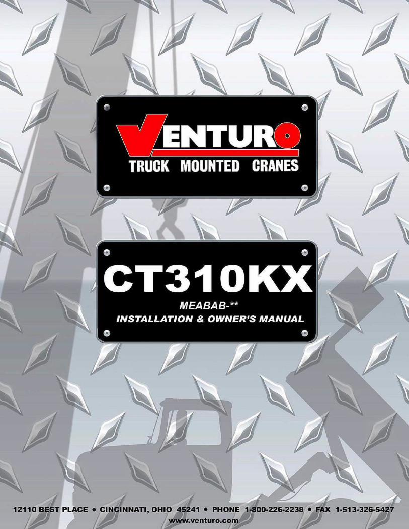
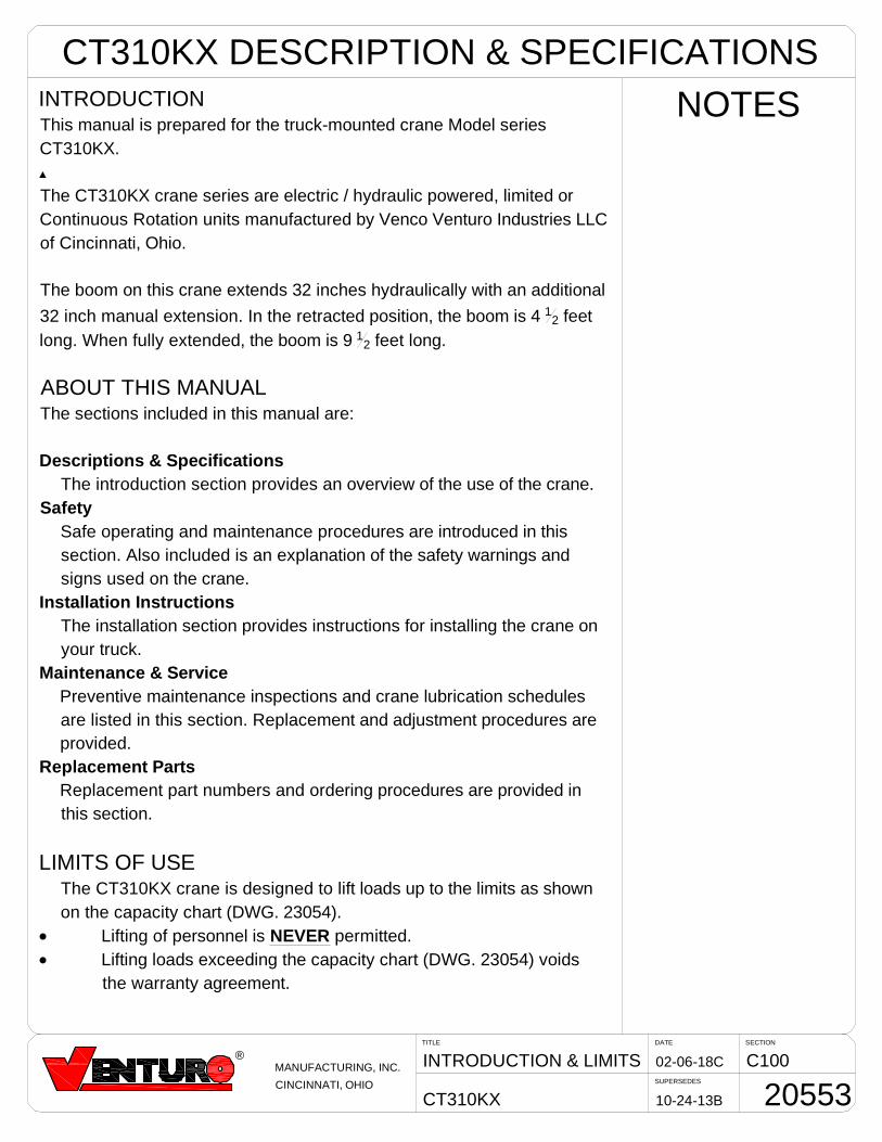
NOTESINTRODUCTIONThis manual is prepared for the truck-mounted crane Model series
CT310KX.
The CT310KX crane series are electric / hydraulic powered, limited or
Continuous Rotation units manufactured by Venco Venturo Industries LLC
of Cincinnati, Ohio.
The boom on this crane extends 32 inches hydraulically with an additional
32 inch manual extension. In the retracted position, the boom is 4 12 feet
long. When fully extended, the boom is 9 12 feet long.
ABOUT THIS MANUALThe sections included in this manual are:
Descriptions & Specifications
The introduction section provides an overview of the use of the crane.
Safety
Safe operating and maintenance procedures are introduced in this
section. Also included is an explanation of the safety warnings and
signs used on the crane.
Installation Instructions
The installation section provides instructions for installing the crane on
your truck.
Maintenance & Service
Preventive maintenance inspections and crane lubrication schedules
are listed in this section. Replacement and adjustment procedures are
provided.
Replacement Parts
Replacement part numbers and ordering procedures are provided in
this section.
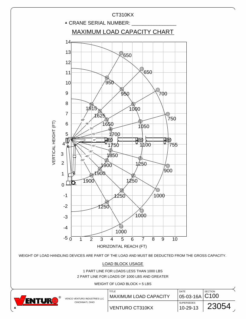
LIMITS OF USEThe CT310KX crane is designed to lift loads up to the limits as shown
on the capacity chart (DWG. 23054).
· Lifting of personnel is NEVER permitted.
· Lifting loads exceeding the capacity chart (DWG. 23054) voids
the warranty agreement.
CT310KX DESCRIPTION & SPECIFICATIONS
VENCO VENTURO INDUSTRIES LLC
CINCINNATI, OHIO
C100MAXIMUM LOAD CAPACITY
VENTURO CT310KX
05-03-16A
DATE SECTION
SUPERSEDES
TITLE
10-29-13
23054
MAXIMUM LOAD CAPACITY CHART
CT310KX
CRANE SERIAL NUMBER: ________________
WEIGHT OF LOAD HANDLING DEVICES ARE PART OF THE LOAD AND MUST BE DEDUCTED FROM THE GROSS CAPACITY.
LOAD BLOCK USAGE
1 PART LINE FOR LOADS LESS THAN 1000 LBS
2 PART LINE FOR LOADS OF 1000 LBS AND GREATER
WEIGHT OF LOAD BLOCK = 5 LBS
2
5
4
3
8 10976543
-1
-2
-3
-4
0
1
210
-5
6
7
8
9
11
12
13
14
10
75511001750
900
1250
1850
1000
1250
1900
1000
1250
1900
1000
1250
1900
750
1050
1700
1650
1000
700
650
950
1625
1915
950
650
HORIZONTAL REACH (FT)
VE
RT
IC
AL H
EIG
HT
(F
T)
SECTIONDATE
SUPERSEDES
TITLE
CT310KX
C10008-12-13A
11-04-02
PNDNT & OVRLD SNSNG
20568
R
MANUFACTURING, INC.
CINCINNATI, OHIO
CT310KX DESCRIPTIONS & SPECIFICATIONS
UP
UP
DOWN
DOWNOUT
IN
WINCH
BOOM
ROTATIONL R
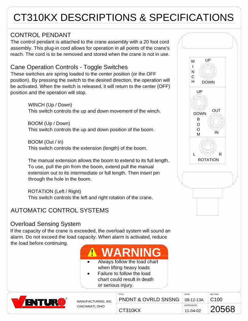
CONTROL PENDANTThe control pendant is attached to the crane assembly with a 20 foot cordassembly. This plug-in cord allows for operation in all points of the crane'sreach. The cord is to be removed and stored when the crane is not in use.
Cane Operation Controls - Toggle SwitchesThese switches are spring loaded to the center position (or the OFFposition). By pressing the switch to the desired direction, the operation willbe activated. When the switch is released, it will return to the center (OFF)position and the operation will stop.
WINCH (Up / Down)This switch controls the up and down movement of the winch.
BOOM (Up / Down)This switch controls the up and down position of the boom.
BOOM (Out / In)This switch controls the extension (length) of the boom.
The manual extension allows the boom to extend to its full length.To use, pull the pin from the boom, extend pull the manualextension out to its intermediate or full length. Then insert pinthrough the hole in the boom.
ROTATION (Left / Right)This switch controls the left and right rotation of the crane.
AUTOMATIC CONTROL SYSTEMS
Overload Sensing SystemIf the capacity of the crane is exceeded, the overload system will sound analarm. Do not exceed the load capacity. When alarm is activated, reducethe load before continuing.
WARNINGD Always follow the load chart
when lifting heavy loadsD Failure to follow the load
chart could result in deathor serious injury.
SECTIONDATE
SUPERSEDES
TITLE
CT310KX
C1003-4-14C
10-24-13B
SETUP & TRAVEL PREP
20569
®MANUFACTURING, INC.
CINCINNATI, OHIO
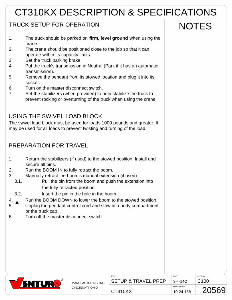
NOTESTRUCK SETUP FOR OPERATION
1. The truck should be parked on firm, level ground when using thecrane.
2. The crane should be positioned close to the job so that it canoperate within its capacity limits.
3. Set the truck parking brake.4. Put the truck's transmission in Neutral (Park if it has an automatic
transmission).5. Remove the pendant from its stowed location and plug it into its
socket.6. Turn on the master disconnect switch.7. Set the stabilizers (when provided) to help stabilize the truck to
prevent rocking or overturning of the truck when using the crane.
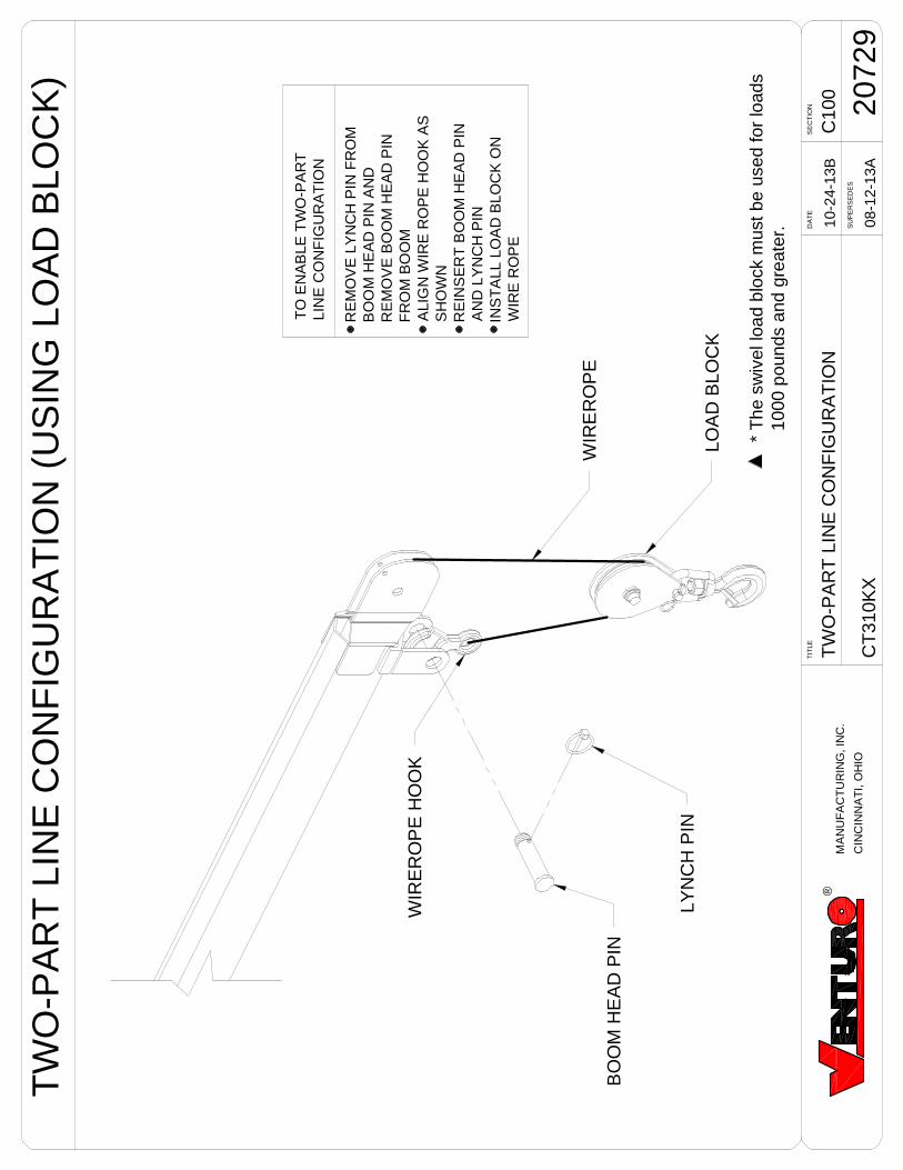
USING THE SWIVEL LOAD BLOCKThe swivel load block must be used for loads 1000 pounds and greater. Itmay be used for all loads to prevent twisting and turning of the load.
PREPARATION FOR TRAVEL
1. Return the stabilizers (if used) to the stowed position. Install andsecure all pins.
2. Run the BOOM IN to fully retract the boom.3. Manually retract the boom's manual extension (if used).
3.1. Pull the pin from the boom and push the extension intothe fully retracted position.
3.2. Insert the pin in the hole in the boom.4. Run the BOOM DOWN to lower the boom to the stowed position.5. Unplug the pendant control cord and stow in a body compartment
or the truck cab.6. Turn off the master disconnect switch.
CT310KX DESCRIPTION & SPECIFICATIONS
TW
O-P
AR
TLI
NE
CO
NF
IGU
RA
TIO
NC
100
CT
310K
X
10-2
4-13
B
DA
TE
SE
CT
ION
SU
PE
RS
ED
ES
TIT
LE
2072
908
-12-
13A
®M
AN
UF
AC
TU
RIN
G,I
NC
.
CIN
CIN
NA
TI,
OH
IO
TO
EN
AB
LET
WO
-PA
RT
LIN
EC
ON
FIG
UR
AT
ION
RE
MO
VE
LYN
CH
PIN
FR
OM
BO
OM
HE
AD
PIN
AN
DR
EM
OV
EB
OO
MH
EA
DP
INF
RO
MB
OO
MA
LIG
NW
IRE
RO
PE
HO
OK
AS
SH
OW
NR
EIN
SE
RT
BO
OM
HE
AD
PIN
AN
DLY
NC
HP
ININ
ST
ALL
LOA
DB
LOC
KO
NW
IRE
RO
PE
LOA
DB
LOC
K
BO
OM
HE
AD
PIN
WIR
ER
OP
EH
OO
K
WIR
ER
OP
E
LYN
CH
PIN
TW
O-P
AR
TLI
NE
CO
NF
IGU
RA
TIO
N(U
SIN
GLO
AD
BLO
CK
)
*T
hesw
ivel
load
bloc
km
ustb
eus
edfo
rlo
ads
1000
poun
dsan
dgr
eate
r.
SECTIONDATE
SUPERSEDES
TITLE
ET6K / CT310KX
C10011-18-14
-
MOUNTING PEDESTAL
26002
®VENCO VENTURO INDUSTRIES LLC
CINCINNATI, OHIO
20480-XX MOUNTING PEDESTAL
20480 (NO DASH)
20480-21
20480-36
8.00
21.00
36.00
10.50TYP
9.00TYP
10.50TYP
9.00TYP
10.50TYP
9.00TYP
PEDESTAL SOLD AS AN OPTION (NOT INCLUDED WITH CRANE)
Ø5.00
Ø5.00
Ø5.00
Ø12.73 4 PLCSFOR 3
4" BOLTS
Ø12.73 4 PLCSFOR 3
4" BOLTS
Ø12.73 4 PLCSFOR 3
4" BOLTS
SECTION 150
SAFETY
8604150
SECTIONDATE
SUPERSEDES
TITLE
CT310KX
C15008-12-13A
11-04-02
GENERAL SAFETY
20556
R
MANUFACTURING, INC.
CINCINNATI, OHIO
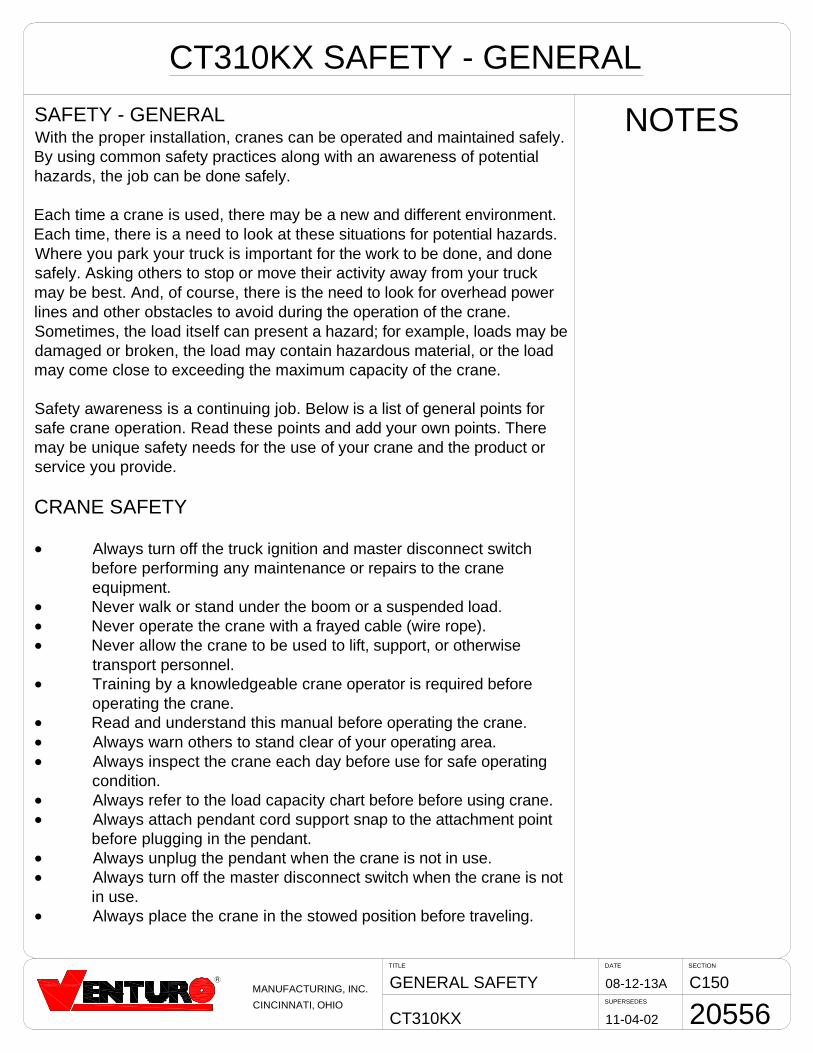
CT310KX SAFETY - GENERAL
NOTESSAFETY - GENERALWith the proper installation, cranes can be operated and maintained safely.By using common safety practices along with an awareness of potentialhazards, the job can be done safely.
Each time a crane is used, there may be a new and different environment.Each time, there is a need to look at these situations for potential hazards.Where you park your truck is important for the work to be done, and donesafely. Asking others to stop or move their activity away from your truckmay be best. And, of course, there is the need to look for overhead powerlines and other obstacles to avoid during the operation of the crane.Sometimes, the load itself can present a hazard; for example, loads may bedamaged or broken, the load may contain hazardous material, or the loadmay come close to exceeding the maximum capacity of the crane.
Safety awareness is a continuing job. Below is a list of general points forsafe crane operation. Read these points and add your own points. Theremay be unique safety needs for the use of your crane and the product orservice you provide.
CRANE SAFETY
D Always turn off the truck ignition and master disconnect switchbefore performing any maintenance or repairs to the craneequipment.
D Never walk or stand under the boom or a suspended load.D Never operate the crane with a frayed cable (wire rope).D Never allow the crane to be used to lift, support, or otherwise
transport personnel.D Training by a knowledgeable crane operator is required before
operating the crane.D Read and understand this manual before operating the crane.D Always warn others to stand clear of your operating area.D Always inspect the crane each day before use for safe operating
condition.D Always refer to the load capacity chart before before using crane.D Always attach pendant cord support snap to the attachment point
before plugging in the pendant.D Always unplug the pendant when the crane is not in use.D Always turn off the master disconnect switch when the crane is not
in use.D Always place the crane in the stowed position before traveling.
SECTIONDATE
SUPERSEDES
TITLE
CT310KX
C15008-12-13A
11-04-02
HZRDS & CLEARANCES
20557
R
MANUFACTURING, INC.
CINCINNATI, OHIO
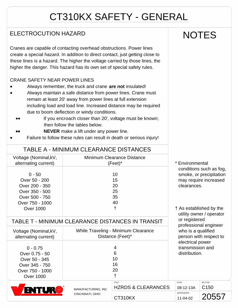
CT310KX SAFETY - GENERAL
NOTESELECTROCUTION HAZARD
Cranes are capable of contacting overhead obstructions. Power linescreate a special hazard. In addition to direct contact, just getting close tothese lines is a hazard. The higher the voltage carried by those lines, thehigher the danger. This hazard has its own set of special safety rules.
CRANE SAFETY NEAR POWER LINESD Always remember, the truck and crane are not insulated!D Always maintain a safe distance from power lines. Crane must
remain at least 20' away from power lines at full extensionincluding load and load line. Increased distance may be requireddue to boom deflection or windy conditions.
DD If you encroach closer than 20', voltage must be known;then follow the tables below.NEVER make a lift under any power line.
D Failure to follow these rules can result in death or serious injury!
Voltage (Nominal,kV,alternating current)
0 - 50Over 50 - 200
Over 200 - 350Over 350 - 500Over 500 - 750
Over 750 - 1000Over 1000
Voltage (Nominal,kV,alternating current)
0 - 0.75Over 0.75 - 50Over 50 - 345
Over 345 - 750Over 750 - 1000
Over 1000
Minimum Clearance Distance(Feet)*
101520253540†
While Traveling - Minimum ClearanceDistance (Feet)*
46
101620†
† As established by theutility owner / operatoror registeredprofessional engineerwho is a qualifiedperson with respect toelectrical powertransmission anddistribution.
* Environmentalconditions such as fog,smoke, or precipitationmay require increasedclearances.
TABLE A - MINIMUM CLEARANCE DISTANCES
TABLE T - MINIMUM CLEARANCE DISTANCES IN TRANSIT

SECTIONDATE
SUPERSEDES
TITLE
CT310KX
C15008-12-13A
11-04-02
WARNING EXPLANATION
20558
R
MANUFACTURING, INC.
CINCINNATI, OHIO
CT310KX SAFETY - GENERAL
NOTESSAFETY WARNINGSSafety warnings have been included in this manual to alert you to theneed for care in specific procedures. These warnings include the use ofthree [3] terms; DANGER, WARNING, and CAUTION. Their uses aredefined as follows:
DANGER
WARNING
CAUTION
Any DANGER indicates that failure to follow this safe practice could resultin death or serious injury.
Any WARNING indicates that failure to follow this safe practice couldresult in injury.
Any CAUTION indicates that failure to follow this instruction could result inminor injury or damage to the equipment.
D Always used to warn ofhazards that could result indeath or serious injury.
D Always used to warn ofhazards that could result ininjury.
D Always used to warn ofhazards that could result inequipment damage orserious injury.
SECTIONDATE
SUPERSEDES
TITLE
CT310KX
C15010-24-13B
08-12-13A
ELECT. HAZARD SIGNS
20559
®MANUFACTURING, INC.
CINCINNATI, OHIO
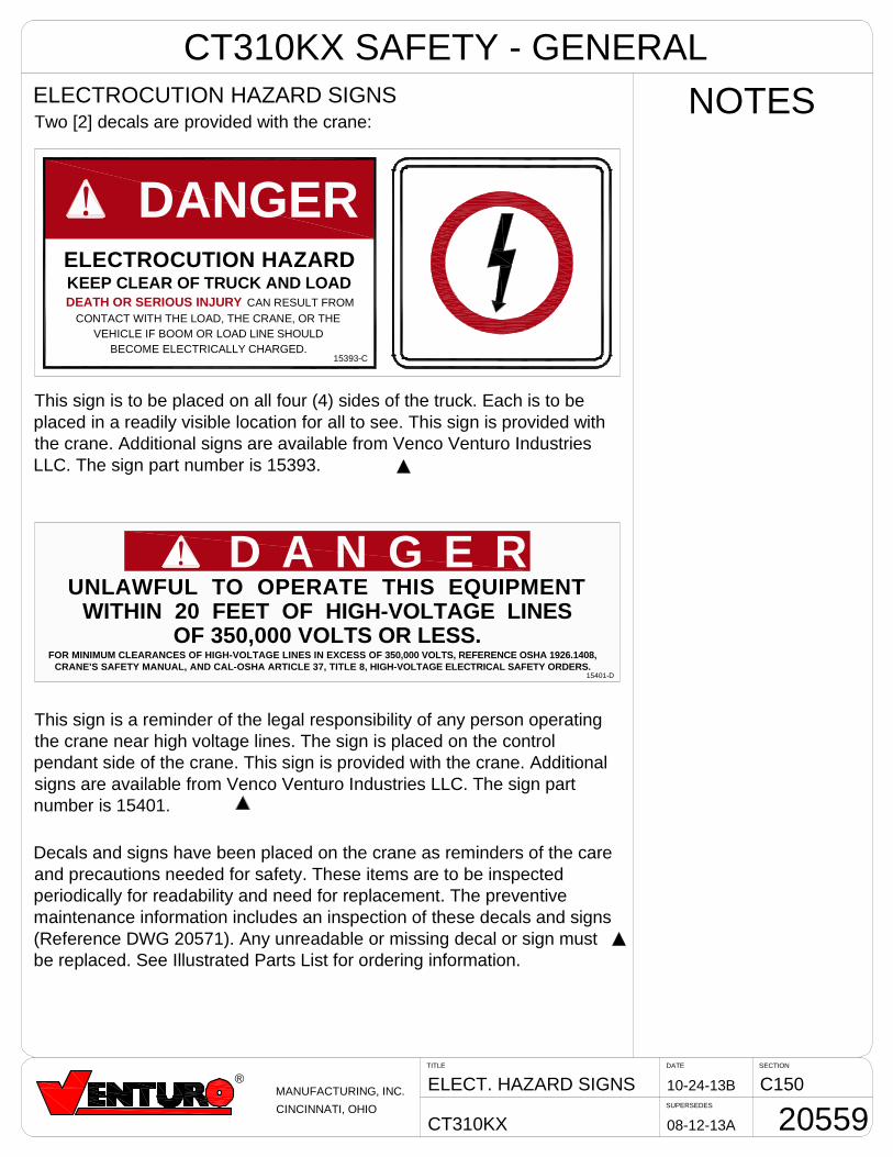
NOTESELECTROCUTION HAZARD SIGNSTwo [2] decals are provided with the crane:
ELECTROCUTION HAZARDKEEP CLEAR OF TRUCK AND LOADDEATH OR SERIOUS INJURY CAN RESULT FROM
CONTACT WITH THE LOAD, THE CRANE, OR THEVEHICLE IF BOOM OR LOAD LINE SHOULD
BECOME ELECTRICALLY CHARGED.15393-C
! DANGER
This sign is to be placed on all four (4) sides of the truck. Each is to beplaced in a readily visible location for all to see. This sign is provided withthe crane. Additional signs are available from Venco Venturo IndustriesLLC. The sign part number is 15393.
D A N G E R!UNLAWFUL TO OPERATE THIS EQUIPMENT
WITHIN 20 FEET OF HIGH-VOLTAGE LINESOF 350,000 VOLTS OR LESS.
FOR MINIMUM CLEARANCES OF HIGH-VOLTAGE LINES IN EXCESS OF 350,000 VOLTS, REFERENCE OSHA 1926.1408,CRANE'S SAFETY MANUAL, AND CAL-OSHA ARTICLE 37, TITLE 8, HIGH-VOLTAGE ELECTRICAL SAFETY ORDERS.
15401-D
This sign is a reminder of the legal responsibility of any person operatingthe crane near high voltage lines. The sign is placed on the controlpendant side of the crane. This sign is provided with the crane. Additionalsigns are available from Venco Venturo Industries LLC. The sign partnumber is 15401.
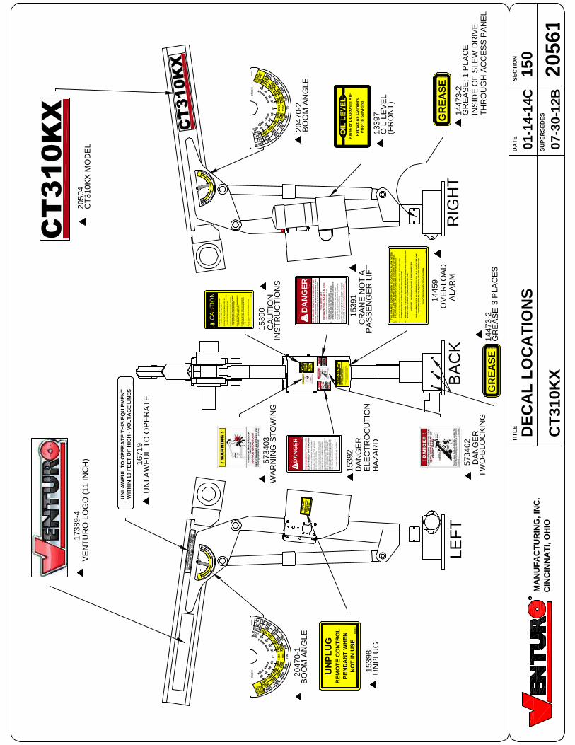
Decals and signs have been placed on the crane as reminders of the careand precautions needed for safety. These items are to be inspectedperiodically for readability and need for replacement. The preventivemaintenance information includes an inspection of these decals and signs(Reference DWG 20571). Any unreadable or missing decal or sign mustbe replaced. See Illustrated Parts List for ordering information.
CT310KX SAFETY - GENERAL
SECTIONDATE
SUPERSEDES
TITLE
CT310KX
C15010-24-13B
08-12-13A
SAFETY SIGNS & DECALS
20560
®MANUFACTURING, INC.
CINCINNATI, OHIO
! DANGER ! DANGER
! WARNING
THE LAST FIVE [5]WRAPS OF WIRE ROPEMUST BE LEFT ON THEDRUM TO ASSIST THEWIRE ROPE CLAMP INHOLDING THE LOAD
DO NOT DISENGAGEWINCH UNDER LOAD
WINCHES ARE NOT TOBE USED FOR THELIFTING OR MOVINGOF PERSONS
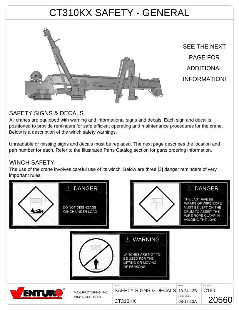
SAFETY SIGNS & DECALSAll cranes are equipped with warning and informational signs and decals. Each sign and decal ispositioned to provide reminders for safe efficient operating and maintenance procedures for the crane.Below is a description of the winch safety warnings.
Unreadable or missing signs and decals must be replaced. The next page describes the location andpart number for each. Refer to the Illustrated Parts Catalog section for parts ordering information.
WINCH SAFETYThe use of the crane involves careful use of its winch. Below are three [3] danger reminders of veryimportant rules.
SEE THE NEXT
PAGE FOR
ADDITIONAL
INFORMATION!
CT310KX SAFETY - GENERAL
2050
4
1539
8
5734
0315
390
CA
UT
ION 14
459
OV
ER
LOA
DA
LAR
M
1738
9-4
1671
9
2047
0-1
2047
0-2
1339
7
1539
1C
RA
NE
NO
TA
1539
2D
AN
GE
RE
LEC
TR
OC
UT
ION
HA
ZA
RD
5734
02D
AN
GE
R
BA
CK
RIG
HT
LEF
T
DE
CA
LL
OC
AT
ION
S15
0
CT
310K
X07
-30-
12B
01-1
4-14
CD
AT
ES
EC
TIO
N
SU
PE
RS
ED
ES
TIT
LE
2056
1M
AN
UF
AC
TU
RIN
G,I
NC
.C
INC
INN
AT
I,O
HIO
VE
NT
UR
OLO
GO
(11
INC
H)
$&
#"
!%
'
UN
PL
UG
RE
MO
TE
CO
NT
RO
LP
EN
DA
NT
WH
EN
NO
TIN
US
E15
398-
F
BO
OM
AN
GLE
UN
PLU
G
WA
RN
ING
ST
OW
ING
TW
O-B
LOC
KIN
G
UN
LA
WF
UL
TOO
PE
RA
TE
TH
ISE
QU
IPM
EN
TW
ITH
IN10
FE
ET
OF
HIG
H-V
OL
TA
GE
LIN
ES
167
19-D
UN
LAW
FU
LT
OO
PE
RA
TE
TH
ISM
AC
HIN
EIS
NO
TIN
SU
LATE
DE
LE
CT
RO
CU
TIO
NH
AZA
RD
MA
INT
AIN
SA
FEC
LEA
RA
NC
ES
FRO
ME
LEC
TR
ICA
LL
INE
SA
ND
AP
PA
RA
TU
S.
YO
UM
US
TA
LLO
WFO
RB
OO
MS
WA
Y,
RO
CK
OR
SA
G,
AN
DE
LEC
TRIC
AL
LIN
EA
ND
LOA
DL
INE
SW
AY
ING
.
TH
ISLI
FTIN
GD
EV
ICE
DO
ES
NO
TP
RO
VID
EP
RO
-T
EC
TIO
NF
RO
MC
ON
TA
CT
WIT
HO
RP
RO
XIM
ITY
TO
AN
EL
EC
TR
ICA
LL
YC
HA
RG
ED
CO
ND
UC
TOR
.
YO
UM
US
TM
AIN
TAIN
AC
LEA
RA
NC
EO
RA
TLE
AS
T10
FE
ET
BE
TWE
EN
AN
YP
AR
TO
FTH
EC
RA
NE
,LO
AD
LIN
EO
RL
OA
D,
AN
DA
NY
ELE
CT
RIC
AL
LIN
EO
RA
PP
AR
AT
US
CA
RR
YIN
GU
PT
O50
,000
VO
LTS
.ON
EF
OO
TA
DD
ITIO
NA
LC
LEA
RA
NC
EIS
RE
QU
IRE
DF
OR
EV
ER
YA
DD
ITIO
NA
L30
,00
0V
OLT
SO
RL
ES
S.
DE
AT
HO
RS
ER
IOU
SIN
JUR
YW
ILL
RE
SU
LT
FRO
MC
ON
TA
CT
OR
INA
DE
QU
ATE
CLE
AR
AN
CE
.
153
92-
E
DA
NG
ER
EL
EC
TR
OC
UT
ION
HA
ZA
RD
DA
NG
ER
153
90-D
!C
AU
TIO
N1.
INS
PE
CT
VE
HIC
LE
AN
DC
RA
NE
INC
LUD
ING
OP
ER
ATI
ON
,P
RIO
RTO
US
ED
AIL
Y.
2.D
ON
OT
US
ETH
ISE
QU
IPM
EN
TE
XC
EP
TO
NS
OL
ID,
LE
VE
LS
UR
FA
CE
WIT
HC
RA
NE
MO
UN
TED
ON
FA
CT
OR
Y-R
EC
OM
ME
ND
ED
TRU
CK
.
3.B
EF
OR
EO
PE
RA
TIN
GT
HE
CR
AN
E,R
EFE
RTO
MA
XIM
UM
LO
AD
(CA
PA
CIT
Y)C
HA
RT
ON
CR
AN
EF
OR
OP
ER
AT
ING
(LO
AD
)LIM
ITA
TIO
NS
.
4.D
ON
OT
OP
ER
AT
E,
WA
LK
,O
RS
TAN
DB
EN
EA
THB
OO
MO
RA
SU
SP
EN
DE
DLO
AD
.
5.U
NP
LU
GP
EN
DA
NT
AN
DS
HU
TO
FFM
AS
TER
DIS
CO
NN
EC
TS
WIT
CH
WH
EN
CR
AN
EN
OT
INU
SE
.
6.F
OR
TR
AV
EL,
BO
OM
MU
ST
BE
INS
TOW
ED
PO
SIT
ION
.
INS
TR
UC
TIO
NS
!C
AU
TIO
N
DA
NG
ER
!T
HIS
CR
AN
EIS
NO
TA
PA
SS
EN
GE
RL
IFT
ITIS
NO
TD
ES
IGN
ED
OR
INT
EN
DE
DTO
BE
US
ED
TOLI
FT,
SU
PP
OR
TO
RO
TH
ER
WIS
ETR
AN
SP
OR
TP
ER
SO
NN
EL.
YO
UM
US
TN
OT
OP
ER
ATE
THIS
CR
AN
EU
NL
ES
S:
1.Y
OU
HA
VE
BE
EN
TR
AIN
ED
INTH
ES
AFE
OP
ER
ATI
ON
OF
THIS
CR
AN
E;A
ND
2.Y
OU
KN
OW
AN
DFO
LLO
WT
HE
SA
FE
TY
AN
DO
PE
RA
TIN
GR
EC
OM
ME
ND
AT
ION
SC
ON
TAIN
ED
INT
HE
MA
NU
FA
CTU
RE
R'S
MA
NU
ALS
,YO
UR
EM
PLO
YE
R'S
WO
RK
RU
LE
S,A
ND
AP
PLIC
AB
LEG
OV
ER
NM
EN
TR
EG
ULA
TIO
NS
.
AN
UN
TR
AIN
ED
OP
ER
AT
OR
SU
BJE
CT
SH
IMS
EL
FA
ND
OT
HE
RS
TO
DE
AT
HO
RS
ER
IOU
SIN
JUR
Y. 153
91-D
PA
SS
EN
GE
RLI
FT
DA
NG
ER
!
1445
9-E
TH
ISC
RA
NE
ISE
QU
IPP
ED
WIT
HA
NO
VE
RLO
AD
ALA
RM
SY
STE
M1.
OV
ER
LOA
DA
LA
RM
HO
RN
SO
UN
DS
IFR
AT
ED
LO
AD
ISE
XCE
ED
ED
AT
AN
YR
EA
CH
.2.
IFA
LA
RM
SO
UN
DS
,RA
ISE
BO
OM
OR
LOW
ER
WIN
CH
TOR
EM
OV
EO
VE
RLO
AD
.
3.A
LW
AY
SR
AIS
EB
OO
MS
LIG
HTL
YB
EF
OR
ELI
FTIN
GLO
AD
.WA
RN
ING
SY
STE
MIN
OP
ER
ATI
VE
WH
EN
CY
LIN
DE
RIS
CO
MP
LETE
LYB
OT
TOM
ED
.
4.A
LAR
MC
AN
BE
TES
TE
DB
YTY
ING
DO
WN
BO
OM
WIT
HW
INC
HC
AB
LEA
ND
OP
ER
ATI
NG
BO
OM
UP
OR
BY
RA
ISIN
GB
OO
MA
GA
INS
TU
PLI
MIT
STO
P.
NO
TIC
E-
WA
RR
AN
TY
VO
IDIF
DIS
CO
NN
EC
TED
TH
ISA
LA
RM
SYS
TE
MH
AS
BE
EN
INS
TA
LLE
DA
SA
SA
FETY
FEA
TUR
ET
OP
RO
TE
CT
BO
THT
HE
EQ
UIP
ME
NT
AN
DT
HE
OP
ER
ATO
R.
DO
NO
TD
ISC
ON
NE
CT
TH
ISS
YS
TEM
TH
ISC
RA
NE
ISE
QU
IPP
ED
WIT
HA
NO
VE
RLO
AD
ALA
RM
SY
STE
M
NO
TIC
E-W
ARR
AN
TYV
OID
IFD
ISC
ON
NE
CTE
D
TH
ISA
LA
RM
SY
ST
EM
HA
SB
EE
NIN
ST
AL
LE
DA
SA
SA
FE
TY
FE
AT
UR
ET
OP
RO
TE
CT
BO
TH
TH
EE
QU
IPM
EN
TA
ND
TH
EO
PE
RA
TO
R.
DO
NO
TD
ISC
ONN
EC
TT
HIS
SY
STE
M
13397-E
Ret
ract
All
Cyl
inde
rsP
rio
rto
Ser
vici
ng
AW
46o
rD
EX
RO
NIII
ATF
OIL
LE
VE
L
OIL
LEV
EL
(FR
ON
T)
CT
310K
XM
OD
EL
14473-2-D
GR
EA
SE
1447
3-2
GR
EA
SE
;1P
LAC
EIN
SID
EO
FS
LEW
DR
IVE
BO
OM
AN
GLE
14473-2-D
GR
EA
SE
0°
1750
1100
755
2047
0-2
0°
1750
1100
755
2047
0-1
CT3
10K
XC
T310
KX
1447
3-2
GR
EA
SE
3P
LAC
ES
TH
RO
UG
HA
CC
ES
SP
AN
EL
VENCO VENTURO INDUSTRIES LLC
CINCINNATI, OHIO
C150SAFETY DECALS
VENTURO CRANES
04-29-16E
DATE SECTION
SUPERSEDES
TITLE
10-24-13D
21353
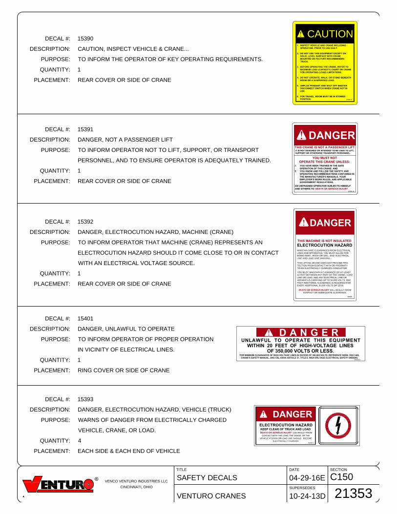
DECAL #: 15390
DESCRIPTION: CAUTION, INSPECT VEHICLE & CRANE...
PURPOSE: TO INFORM THE OPERATOR OF KEY OPERATING REQUIREMENTS.
QUANTITY: 1
PLACEMENT: REAR COVER OR SIDE OF CRANE
DECAL #: 15391
DESCRIPTION: DANGER, NOT A PASSENGER LIFT
PURPOSE: TO INFORM OPERATOR NOT TO LIFT, SUPPORT, OR TRANSPORT
PERSONNEL, AND TO ENSURE OPERATOR IS ADEQUATELY TRAINED.
QUANTITY: 1
PLACEMENT: REAR COVER OR SIDE OF CRANE
15390-D
!CAUTION
1. INSPECT VEHICLE AND CRANE INCLUDING
OPERATION, PRIOR TO USE DAILY.
2. DO NOT USE THIS EQUIPMENT EXCEPT ON
SOLID, LEVEL SURFACE WITH CRANE
MOUNTED ON FACTORY-RECOMMENDED
TRUCK.
3. BEFORE OPERATING THE CRANE, REFER TO
MAXIMUM LOAD (CAPACITY) CHART ON CRANE
FOR OPERATING (LOAD) LIMITATIONS.
4. DO NOT OPERATE, WALK, OR STAND BENEATH
BOOM OR A SUSPENDED LOAD.
5. UNPLUG PENDANT AND SHUT OFF MASTER
DISCONNECT SWITCH WHEN CRANE NOT IN
USE.
6. FOR TRAVEL, BOOM MUST BE IN STOWED
POSITION.
DANGER!THIS CRANE IS NOT A PASSENGER LIFT
IT IS NOT DESIGNED OR INTENDED TO BE USED TO LIFT,
SUPPORT OR OTHERWISE TRANSPORT PERSONNEL.
YOU MUST NOT
OPERATE THIS CRANE UNLESS:
1. YOU HAVE BEEN TRAINED IN THE SAFE
OPERATION OF THIS CRANE; AND
2. YOU KNOW AND FOLLOW THE SAFETY AND
OPERATING RECOMMENDATIONS CONTAINED IN
THE MANUFACTURER'S MANUALS, YOUR
EMPLOYER'S WORK RULES, AND APPLICABLE
GOVERNMENT REGULATIONS.
AN UNTRAINED OPERATOR SUBJECTS HIMSELF
AND OTHERS TO DEATH OR SERIOUS INJURY .
15391-D
THIS MACHINE IS NOT INSULATED
ELECTROCUTION HAZARD
MAINTAIN SAFE CLEARANCES FROM ELECTRICAL
LINES AND APPARATUS. YOU MUST ALLOW FOR
BOOM SWAY, ROCK OR SAG, AND ELECTRICAL
LINE AND LOAD LINE SWAYING.
THIS LIFTING DEVICE DOES NOT PROVIDE PRO-
TECTION FROM CONTACT WITH OR PROXIMITY
TO AN ELECTRICALLY CHARGED CONDUCTOR.
YOU MUST MAINTAIN A CLEARANCE OR AT LEAST
10 FEET BETWEEN ANY PART OF THE CRANE, LOAD
LINE OR LOAD, AND ANY ELECTRICAL LINE OR
APPARATUS CARRYING UP TO 50,000 VOLTS. ONE
FOOT ADDITIONAL CLEARANCE IS REQUIRED FOR
EVERY ADDITIONAL 30,000 VOLTS OR LESS.
DEATH OR SERIOUS INJURY WILL RESULT FROM
CONTACT OR INADEQUATE CLEARANCE.
15392-E
DANGER!
D A N G E R!
UNLAWFUL TO OPERATE THIS EQUIPMENT
WITHIN 20 FEET OF HIGH-VOLTAGE LINES
OF 350,000 VOLTS OR LESS.
FOR MINIMUM CLEARANCES OF HIGH-VOLTAGE LINES IN EXCESS OF 350,000 VOLTS, REFERENCE OSHA 1926.1408,
CRANE'S SAFETY MANUAL, AND CAL-OSHA ARTICLE 37, TITLE 8, HIGH-VOLTAGE ELECTRICAL SAFETY ORDERS.
15401-D
ELECTROCUTION HAZARD
KEEP CLEAR OF TRUCK AND LOAD
DEATH OR SERIOUS INJURY CAN RESULT FROM
CONTACT WITH THE LOAD, THE CRANE, OR THE
VEHICLE IF BOOM OR LOAD LINE SHOULD BECOME
ELECTRICALLY CHARGED.
15393-C
!DANGER
DECAL #: 15392
DESCRIPTION: DANGER, ELECTROCUTION HAZARD, MACHINE (CRANE)
PURPOSE: TO INFORM OPERATOR THAT MACHINE (CRANE) REPRESENTS AN
ELECTROCUTION HAZARD SHOULD IT COME CLOSE TO OR IN CONTACT
WITH AN ELECTRICAL VOLTAGE SOURCE.
QUANTITY: 1
PLACEMENT: REAR COVER OR SIDE OF CRANE
DECAL #: 15401
DESCRIPTION: DANGER, UNLAWFUL TO OPERATE
PURPOSE: TO INFORM OPERATOR OF PROPER OPERATION
IN VICINITY OF ELECTRICAL LINES.
QUANTITY: 1
PLACEMENT: RING COVER OR SIDE OF CRANE
DECAL #: 15393
DESCRIPTION: DANGER, ELECTROCUTION HAZARD, VEHICLE (TRUCK)
PURPOSE: WARNS OF DANGER FROM ELECTRICALLY CHARGED
VEHICLE, CRANE, OR LOAD.
QUANTITY: 4
PLACEMENT: EACH SIDE & EACH END OF VEHICLE
PART NO.: 15513
DECAL: MASTER DISCONNECT SWITCH
FUNCTION: To inform the operator of locationand operation of master disconnectswitch.
QUANTITY: 1
PLACEMENT: On master disconnect switch bracket.
SECTIONDATE
SUPERSEDES
TITLE
CRANES
C15006-06-14C
04-02-13B
SAFETY DECALS
21384
®VENCO VENTURO INDUSTRIES LLC
CINCINNATI, OHIO
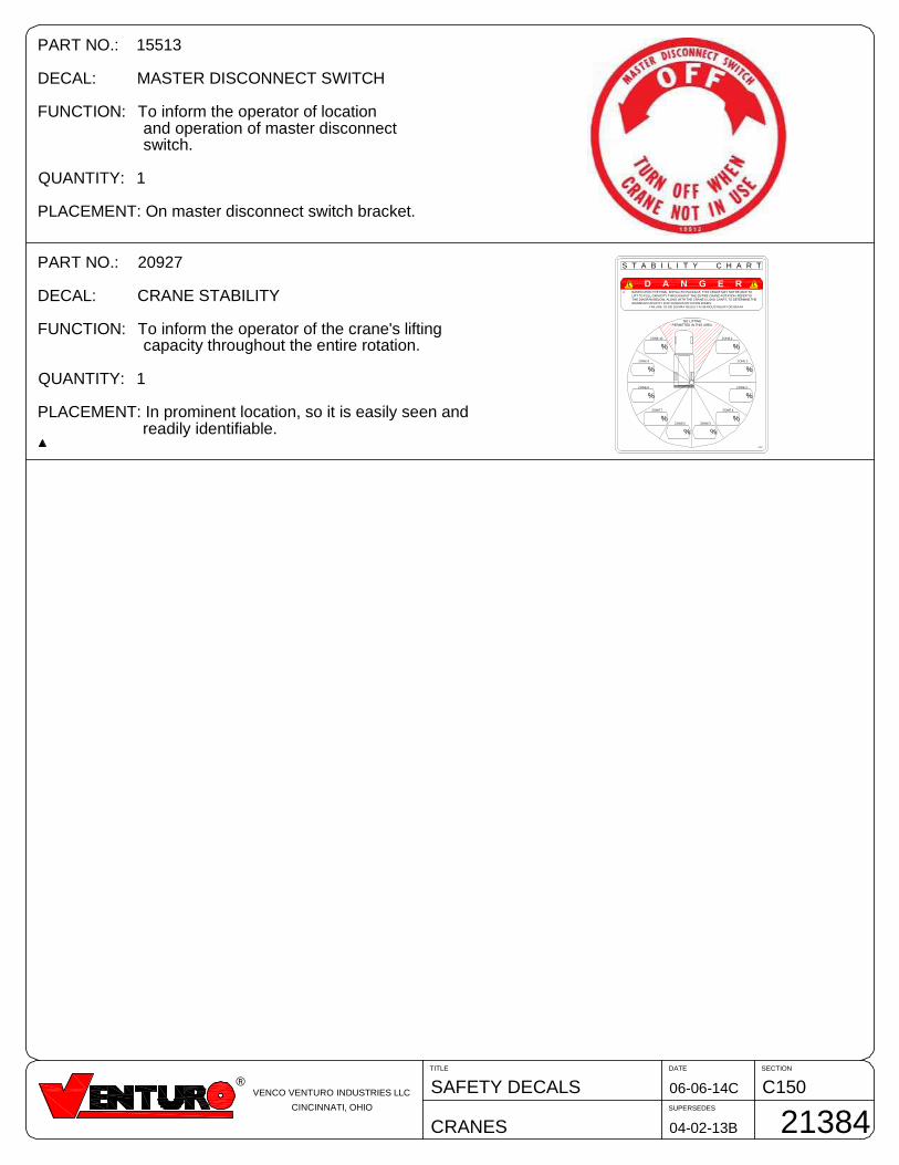
PART NO.: 20927
DECAL: CRANE STABILITY
FUNCTION: To inform the operator of the crane's liftingcapacity throughout the entire rotation.
QUANTITY: 1
PLACEMENT: In prominent location, so it is easily seen andreadily identifiable.
%
%
%
%
%%
%
%
%
%
NO LIFTING
S T A B I L I T Y C H A R T
20927
PERMITTED IN THIS AREA
ZONE 1ZONE 10
ZONE 9
ZONE 8
ZONE 2
ZONE 3
ZONE 4
ZONE 5ZONE 6
ZONE 7
D BASED UPON THE FINAL INSTALLED PACKAGE, THIS CRANE MAY NOT BE ABLE TOLIFT TO FULL CAPACITY THROUGHOUT THE ENTIRE CRANE ROTATION. REFER TOTHE DIAGRAM BELOW, ALONG WITH THE CRANE'S LOAD CHART, TO DETERMINE THEMAXIMUM CAPACITY FOR VARIOUS ROTATION ZONES.
FAILURE TO DO SO MAY RESULT IN SERIOUS INJURY OR DEATH
D A N G E R
SECTIONDATE
SUPERSEDES
TITLE
VENTURO CT310KX
C15010-24-13B
08-12-13A
DECAL DRAWING & LIST
21377
®MANUFACTURING, INC.
CINCINNATI, OHIO
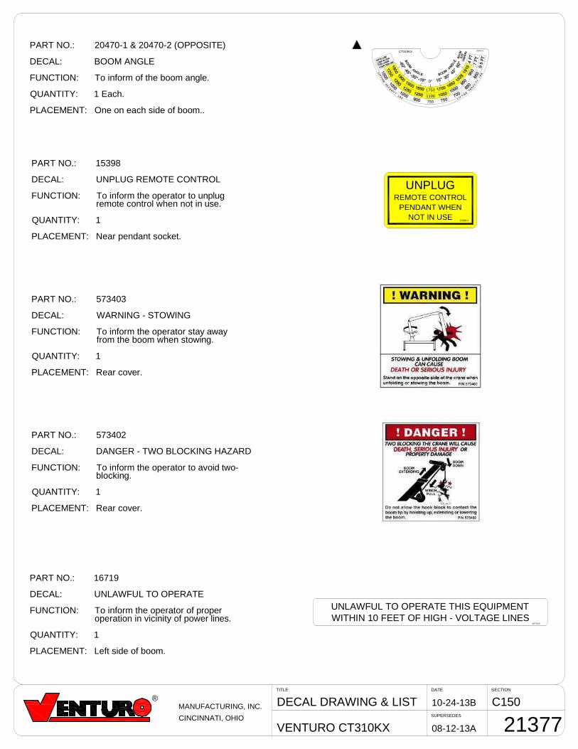
PART NO.: 15398
DECAL: UNPLUG REMOTE CONTROL
FUNCTION: To inform the operator to unplugremote control when not in use.
QUANTITY: 1
PLACEMENT: Near pendant socket.
PART NO.: 20470-1 & 20470-2 (OPPOSITE)
DECAL: BOOM ANGLE
FUNCTION: To inform of the boom angle.
QUANTITY: 1 Each.
PLACEMENT: One on each side of boom..
PART NO.: 16719
DECAL: UNLAWFUL TO OPERATE
FUNCTION: To inform the operator of properoperation in vicinity of power lines.
QUANTITY: 1
PLACEMENT: Left side of boom.
PART NO.: 573403
DECAL: WARNING - STOWING
FUNCTION: To inform the operator stay awayfrom the boom when stowing.
QUANTITY: 1
PLACEMENT: Rear cover.
PART NO.: 573402
DECAL: DANGER - TWO BLOCKING HAZARD
FUNCTION: To inform the operator to avoid two-blocking.
QUANTITY: 1
PLACEMENT: Rear cover.
UNPLUGREMOTE CONTROL
PENDANT WHENNOT IN USE
15398-F
UNLAWFUL TO OPERATE THIS EQUIPMENTWITHIN 10 FEET OF HIGH - VOLTAGE LINES
16719-D
0°
1750
1100755
20470-1CT310KX
SECTIONDATE
SUPERSEDES
TITLE
CT310KX
C15010-24-13D
08-12-13C
DECAL DRAWING & LIST
21378
®MANUFACTURING, INC.
CINCINNATI, OHIO
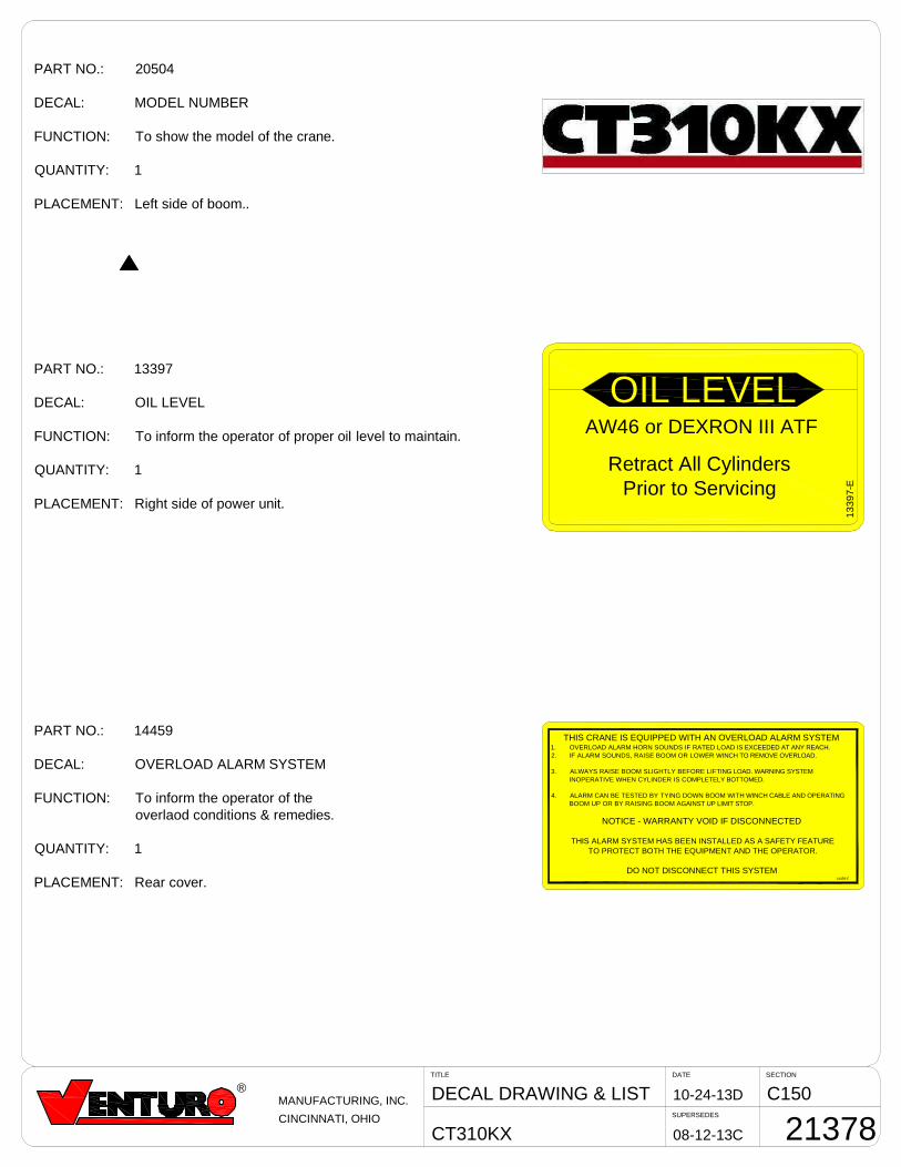
PART NO.: 20504
DECAL: MODEL NUMBER
FUNCTION: To show the model of the crane.
QUANTITY: 1
PLACEMENT: Left side of boom..
PART NO.: 13397
DECAL: OIL LEVEL
FUNCTION: To inform the operator of proper oil level to maintain.
QUANTITY: 1
PLACEMENT: Right side of power unit.
PART NO.: 14459
DECAL: OVERLOAD ALARM SYSTEM
FUNCTION: To inform the operator of theoverlaod conditions & remedies.
QUANTITY: 1
PLACEMENT: Rear cover.
1339
7-E
Retract All CylindersPrior to Servicing
AW46 or DEXRON III ATF
OIL LEVEL
14459-E
THIS CRANE IS EQUIPPED WITH AN OVERLOAD ALARM SYSTEM1. OVERLOAD ALARM HORN SOUNDS IF RATED LOAD IS EXCEEDED AT ANY REACH.2. IF ALARM SOUNDS, RAISE BOOM OR LOWER WINCH TO REMOVE OVERLOAD.
3. ALWAYS RAISE BOOM SLIGHTLY BEFORE LIFTING LOAD. WARNING SYSTEMINOPERATIVE WHEN CYLINDER IS COMPLETELY BOTTOMED.
4. ALARM CAN BE TESTED BY TYING DOWN BOOM WITH WINCH CABLE AND OPERATINGBOOM UP OR BY RAISING BOOM AGAINST UP LIMIT STOP.
NOTICE - WARRANTY VOID IF DISCONNECTED
THIS ALARM SYSTEM HAS BEEN INSTALLED AS A SAFETY FEATURETO PROTECT BOTH THE EQUIPMENT AND THE OPERATOR.
DO NOT DISCONNECT THIS SYSTEM

SECTION 200
INSTALLATION
7607200A

SECTIONDATE
SUPERSEDES
TITLE
CT310KX
C2004-25-14J
2-18-14G
INSTALL INSTRUCTIONS
20563
®MANUFACTURING, INC.
CINCINNATI, OHIO
CT310KX INSTALLATION INSTRUCTIONS
NOTESINSTALLATION PROCEDUREYour new crane is shipped in a ready-to-install condition. Follow theinstructions in this section tp properly install the crane onto your truck.
INSPECT FOR SHIPPING DAMAGEInspect the crane immediately upon receipt, even if installation will notoccur immediately.D Remove packaging materials as neededD Inspect for crushed, bent, or otherwise damaged conditionsD Report any damage found to the carrier
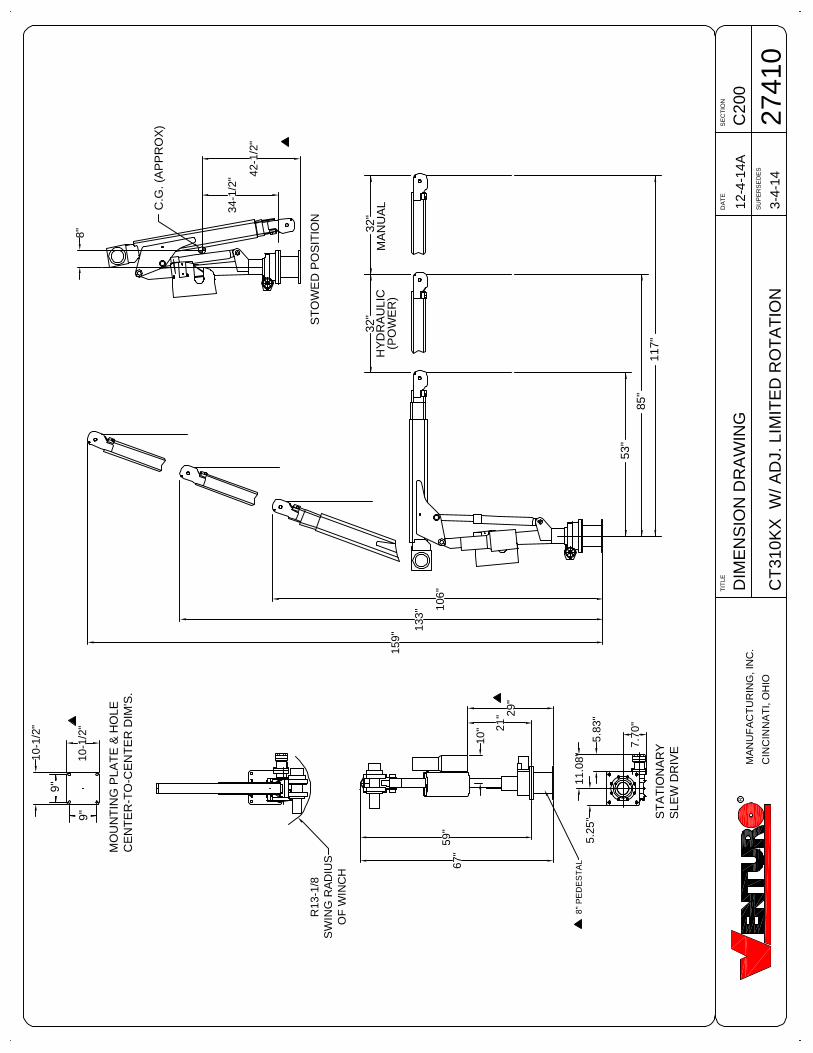
CRANE MOUNTINGRefer to drawing 27410.
Recommended Mounting Hardware:
The crane base is mounted using four [4] 3/4-10 x 2 34" (bolt length will
vary per mounting application), zinc - plated (GR.5 or greater) hex headcap screw bolts, [8] flat washers, and [4] nylon - insert hex 'Full' lock nuts.
Note: This hardware is NOT supplied due to the varying bolt lengthrequirements per application.
Torque hex nuts to standard toque value of 230 ft.-lbs.
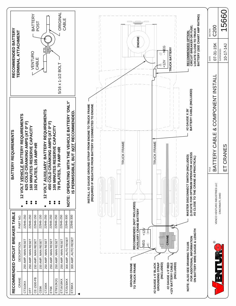
INSTALL BATTERY CABLESRefer to drawing 20565
1. Install #2 gauge wiring1.1. Be sure to install a circuit breaker into the wiring from the battery
(P/N 22946 recommended).2. Install grounding straps
2.1. Install #2 gauge grounding strap from rane base to truck frame.2.2. If truck battery negative terminal is connected to engine, install a
#2 gauge grounding strap from the engine to truck frame.
WIRE ROPE INSTALLATIONRefer to drawing 20574 (MAINTENANCE SECTION) for information onwire rope installation / replacement.
C20
0D
IME
NS
ION
DR
AW
ING
CT
310K
XW
/AD
J.LI
MIT
ED
RO
TA
TIO
N
12-4
-14A
DA
TE
SE
CT
ION
SU
PE
RS
ED
ES
TIT
LE
2741
0R
MA
NU
FA
CT
UR
ING
,IN
C.
CIN
CIN
NA
TI,
OH
IO
C.G
.(A
PP
RO
X)
32"
32"
117"
85"
53"
ST
OW
ED
PO
SIT
ION
MA
NU
AL
(PO
WE
R)
HY
DR
AU
LIC
59"
34-1
/2"
ST
AT
ION
AR
YS
LEW
DR
IVE
8"
R13
-1/8
SW
ING
RA
DIU
SO
FW
INC
H
11.0
8"
5.83
"
7.70
"
5.25
"
3-4-
14
8"P
ED
ES
TA
L
9"
9"
MO
UN
TIN
GP
LAT
E&
HO
LEC
EN
TE
R-T
O-C
EN
TE
RD
IM'S
.
10-1
/2"
10-1
/2"
159"
133"
106"
10" 21
" 29"
67"
42-1
/2"
SECTIONDATE
SUPERSEDES
TITLE
CT310KX
C2003-20-14D
1-15-14C
BASE MOUNTING DIM
20714R
MANUFACTURING, INC.
CINCINNATI, OHIO
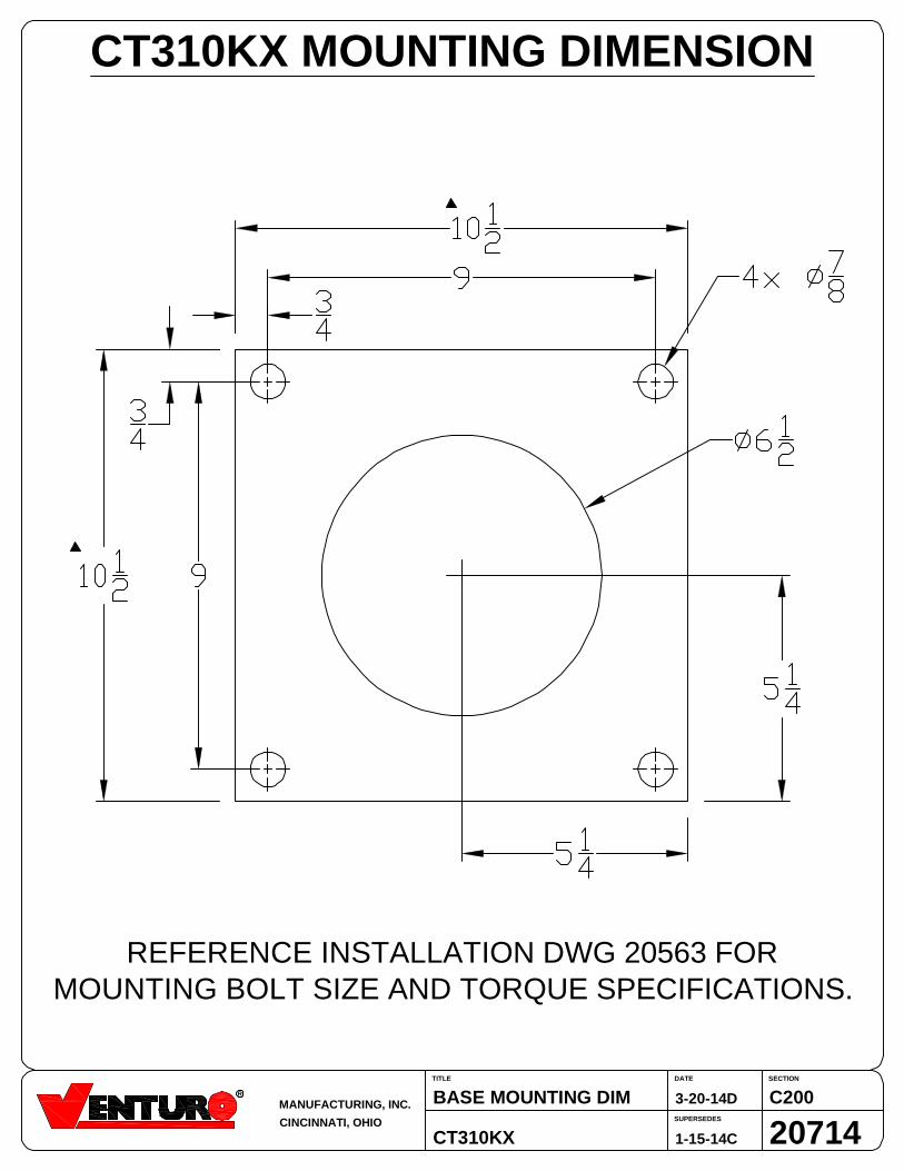
CT310KX MOUNTING DIMENSION
REFERENCE INSTALLATION DWG 20563 FORMOUNTING BOLT SIZE AND TORQUE SPECIFICATIONS.
SECTIONDATE
SUPERSEDES
TITLE
CT310KX w/ ADJ. ROT.
C2004-9-14AFACTORY-SET ROT. STOP
27413
®MANUFACTURING, INC.
CINCINNATI, OHIO
3-20-14
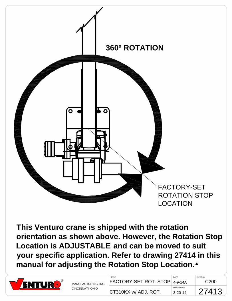
360º ROTATION
FACTORY-SETROTATION STOPLOCATION
This Venturo crane is shipped with the rotationorientation as shown above. However, the Rotation StopLocation is ADJUSTABLE and can be moved to suityour specific application. Refer to drawing 27414 in thismanual for adjusting the Rotation Stop Location.
SECTIONDATE
SUPERSEDES
TITLE
CT310KX w/ ADJ. ROT.
C20012-01-15AINST. ADJ. ROT. STOPS
27414
®MANUFACTURING, INC.
CINCINNATI, OHIO
03-20-14
46
30
47
58
FACTORY-SETROTATION STOP
LOCATION
FACTORY-SETROTATION STOP
LOCATION
CA
B
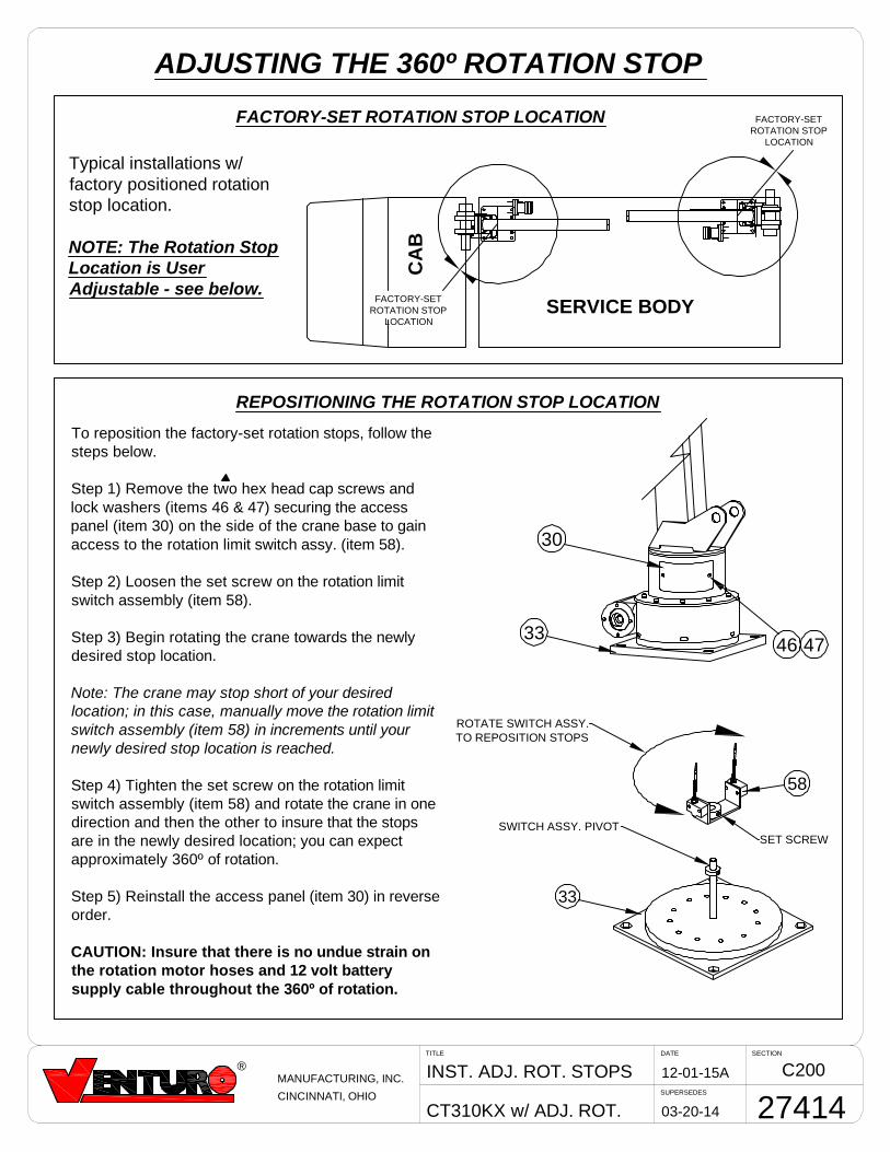
ADJUSTING THE 360º ROTATION STOP
SERVICE BODY
Typical installations w/factory positioned rotationstop location.
NOTE: The Rotation StopLocation is UserAdjustable - see below.
FACTORY-SET ROTATION STOP LOCATION
33
SET SCREW
ROTATE SWITCH ASSY.TO REPOSITION STOPS
33
To reposition the factory-set rotation stops, follow thesteps below.
Step 1) Remove the two hex head cap screws andlock washers (items 46 & 47) securing the accesspanel (item 30) on the side of the crane base to gainaccess to the rotation limit switch assy. (item 58).
Step 2) Loosen the set screw on the rotation limitswitch assembly (item 58).
Step 3) Begin rotating the crane towards the newlydesired stop location.
Note: The crane may stop short of your desiredlocation; in this case, manually move the rotation limitswitch assembly (item 58) in increments until yournewly desired stop location is reached.
Step 4) Tighten the set screw on the rotation limitswitch assembly (item 58) and rotate the crane in onedirection and then the other to insure that the stopsare in the newly desired location; you can expectapproximately 360º of rotation.
Step 5) Reinstall the access panel (item 30) in reverseorder.
CAUTION: Insure that there is no undue strain onthe rotation motor hoses and 12 volt batterysupply cable throughout the 360º of rotation.
REPOSITIONING THE ROTATION STOP LOCATION
SWITCH ASSY. PIVOT
C2
00
BA
TT
ER
YC
AB
LE
&C
OM
PO
NE
NT
INS
TA
LL
ET
CR
AN
ES
07-3
1-1
5K
DA
TE
SE
CT
ION
SU
PE
RS
ED
ES
TIT
LE
15660
10-1
7-1
4J
®V
EN
CO
VE
NT
UR
OIN
DU
ST
RIE
SLLC
CIN
CIN
NA
TI,
OH
IO
+1
2V
TR
UC
KB
AT
TE
RY
RE
CO
MM
EN
DE
DC
IRC
UIT
BR
EA
KE
RT
AB
LE
CR
AN
E
CT
310
KX
DT
7
CE
-15
00-F
B
CE
6K
CT
200X
ET
6K
ET
8/1
2K
(X)
ET
16/1
8K
X
ET
25/3
0K
X
ET
36K
X
PA
RT
NO
.
229
46
-250
229
46
-250
229
46
-150
229
46
-150
229
46
-250
229
46
-250
229
46
-250
229
46
-250
229
46
-300
229
46
-300
DE
SC
RIP
TIO
N
250
AM
P,
MA
NR
ES
ET
250
AM
P,
MA
NR
ES
ET
150
AM
P,
MA
NR
ES
ET
150
AM
P,
MA
NR
ES
ET
250
AM
P,
MA
NR
ES
ET
250
AM
P,
MA
NR
ES
ET
250
AM
P,
MA
NR
ES
ET
250
AM
P,
MA
NR
ES
ET
300
AM
P,
AU
TO
RE
SE
T
300
AM
P,
AU
TO
RE
SE
T
-N
EG
RE
CO
MM
EN
DE
DO
PT
ION
:C
IRC
UIT
BR
EA
KE
RO
RF
US
E;
LO
CA
TE
CL
OS
ET
OT
RU
CK
BA
TT
ER
Y(S
EE
CH
AR
TA
MP
RA
TIN
G)
+1
2V
-N
EG
RE
CO
MM
EN
DE
D(N
OT
INC
LU
DE
D)
AU
XIL
IAR
YC
RA
NE
BA
TT
ER
Y
TR
UC
KF
RA
ME
TR
UC
KF
RA
ME
MA
ST
ER
DIS
CO
NN
EC
TS
WIT
CH
(IN
CL
UD
ED
)(L
OC
AT
EF
OR
OP
TIM
UM
OP
ER
AT
OR
AC
CE
SS
AS
CL
OS
ET
OT
HE
CR
AN
EA
SP
RA
CT
ICA
L)
#2
GA
UG
Ex
5'B
LA
CK
GR
OU
ND
ING
ST
RA
P(I
NC
LU
DE
D)
#2
GA
UG
Ex
5'R
ED
+1
2V
BA
TT
ER
YC
AB
LE
(IN
CL
UD
ED
)
#2
GA
UG
EX
26'
BA
TT
ER
YC
AB
LE
(IN
CL
UD
ED
)
INS
TA
LL
#2
GA
UG
EG
RO
UN
DS
TR
AP
FR
OM
EN
GIN
ET
OT
RU
CK
FR
AM
E(R
EQ
UIR
ED
IFN
EG
AT
IVE
FR
OM
BA
TT
ER
YIS
CO
NN
EC
TE
DT
OE
NG
INE
EN
GIN
E
BA
TT
ER
YR
EQ
UIR
EM
EN
TS
·1
2V
OL
TV
EH
ICL
EB
AT
TE
RY
RE
QU
IRE
ME
NT
S··
62
5C
OL
DC
RA
NK
ING
AM
PS
(AT
0º
F)
··1
60
MIN
UT
ES
RE
SE
RV
EC
AP
AC
ITY
··1
02
PL
AT
ES
,1
05
AM
P-H
R
·1
2V
OL
TA
UX
ILIA
RY
BA
TT
ER
YR
EQ
UIR
EM
EN
TS
··4
50
CO
LD
CR
AN
KIN
GA
MP
S(A
T0º
F)
··1
00
MIN
UT
ES
RE
SE
RV
EC
AP
AC
ITY
··7
8P
LA
TE
S,
70
AM
P-H
R
NO
TE
:O
PE
RA
TIN
GW
ITH
TH
EV
EH
ICL
EB
AT
TE
RY
'ON
LY
'IS
PE
RM
ISS
IBL
E,B
UT
NO
TR
EC
OM
ME
ND
ED
.
VE
NT
UR
OC
AB
LE
5/1
6x
1-1
/2B
OLT
OR
IGIN
AL
CA
BLE
GR
OU
ND
CR
AN
ET
OT
RU
CK
FR
AM
E
RE
CO
MM
EN
DE
DB
AT
TE
RY
TE
RM
INA
LA
TT
AC
HM
EN
T BA
TT
ER
YP
OS
T
CR
AN
E
NO
TE
:A
LS
OS
EE
DR
AW
ING
71
11
05
FO
RA
DD
ITIO
NA
LIN
FO
RM
AT
ION
ON
BA
TT
ER
YW
IRE
GA
UG
E&
LE
NG
TH
SECTIONDATE
SUPERSEDES
TITLE
CT310KX
C20008-12-13A
11-04-02
FINAL PREP FOR USE
20566
R
MANUFACTURING, INC.
CINCINNATI, OHIO
CT310KX INSTALLATION INSTRUCTIONS
NOTESFINAL PREPARATION FOR USE
1. Check all bolts and nuts for tightness.
2. Check all electrical connections for tightness.
3. Inspect the entire crane to be sure that it is ready for use.
4. Verify that the hydraulic reservoir is filled with hydraulic fluid (withboth cylinders fully retracted).
5. Check the crane operation.5.1. Put the truck's transmission in Neutral (Park if it has an
automatic transmission).
5.2. Remove the pendant from its stowed location and plug itinto its socket.
5.3. Check each of the four operations by operating eachswitch in both directions:
5.3.1. WINCH down / up5.3.2. BOOM up / down5.3.3. BOOM out / in5.3.4. ROTATION left / right
NOTE: The crane is now ready for operation.
6. After 10 hours of operation, repeat steps 1 through 4.
SECTION 300
MAINTENANCE
&
SERVICE
7607300A
SECTIONDATE
SUPERSEDES
TITLE
CT310KX
C30008-12-13A
11-04-02
PRVNTV MAINTENANCE
20571
R
MANUFACTURING, INC.
CINCINNATI, OHIO
CT310KX MAINTENANCE & SERVICE
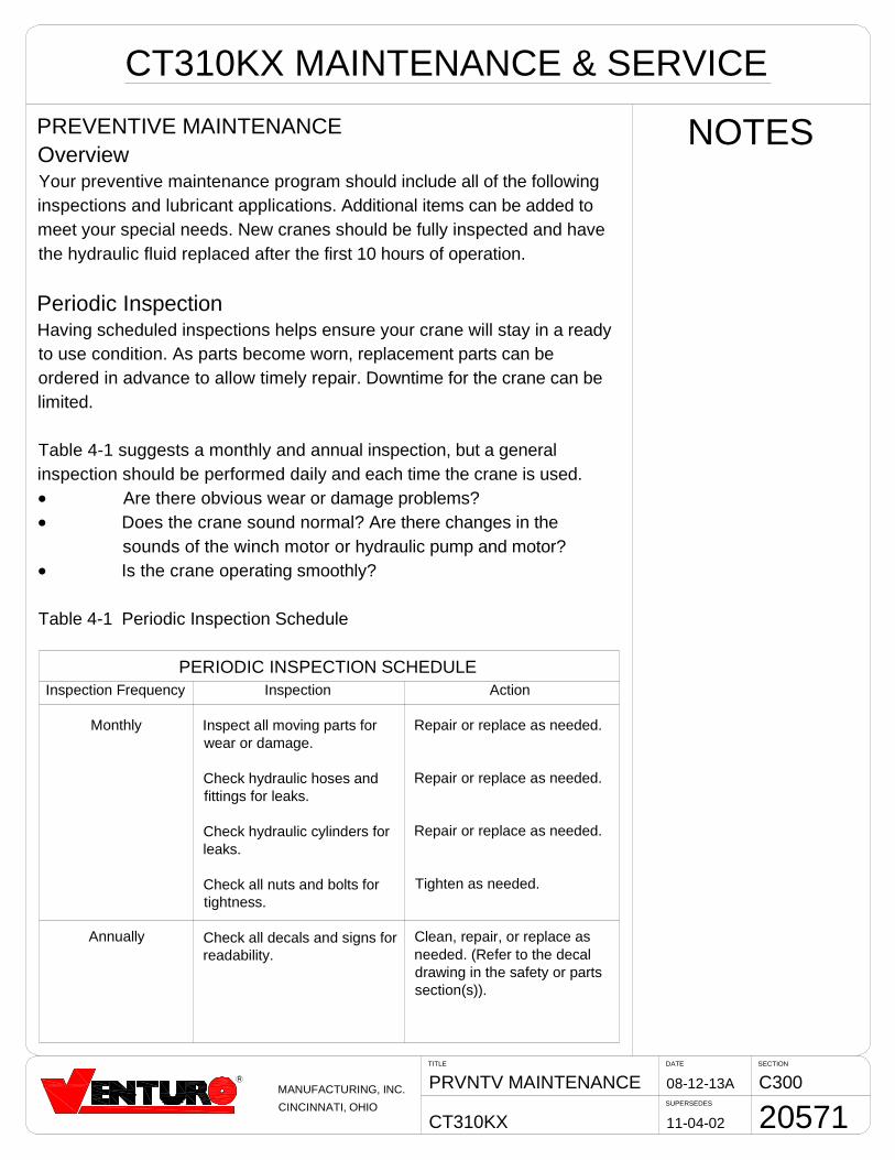
NOTESPREVENTIVE MAINTENANCEOverviewYour preventive maintenance program should include all of the followinginspections and lubricant applications. Additional items can be added tomeet your special needs. New cranes should be fully inspected and havethe hydraulic fluid replaced after the first 10 hours of operation.
Periodic InspectionHaving scheduled inspections helps ensure your crane will stay in a readyto use condition. As parts become worn, replacement parts can beordered in advance to allow timely repair. Downtime for the crane can belimited.
Table 4-1 suggests a monthly and annual inspection, but a generalinspection should be performed daily and each time the crane is used.D Are there obvious wear or damage problems?D Does the crane sound normal? Are there changes in the
sounds of the winch motor or hydraulic pump and motor?D Is the crane operating smoothly?
Table 4-1 Periodic Inspection Schedule
PERIODIC INSPECTION SCHEDULEInspection Frequency
Monthly
Annually
Inspection
Inspect all moving parts forwear or damage.
Check hydraulic hoses andfittings for leaks.
Check hydraulic cylinders forleaks.
Check all nuts and bolts fortightness.
Check all decals and signs forreadability.
Action
Repair or replace as needed.
Repair or replace as needed.
Repair or replace as needed.
Tighten as needed.
Clean, repair, or replace asneeded. (Refer to the decaldrawing in the safety or partssection(s)).
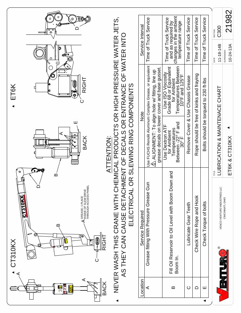
C30
0LU
BR
ICA
TIO
N&
MA
INT
EN
AC
EC
HA
RT
ET
6K&
CT
310K
X
11-1
8-14
B
DA
TE
SE
CT
ION
SU
PE
RS
ED
ES
TIT
LE
2198
210
-24-
13A
Ser
vice
Inte
rval
Not
eLo
catio
nS
ervi
ceR
equi
red
Tim
eof
Tru
ckS
ervi
ceU
seF
UC
HS
Ren
olit
Alu
min
umC
ompl
exG
reas
e,or
equi
vale
ntG
reas
efit
ting
With
Pre
ssur
eG
reas
eG
unA
Tim
eof
Tru
ckS
ervi
ce
Tim
eof
Tru
ckS
ervi
ce
Lubr
icat
eG
ear
Tee
th
B C DR
ope
shou
ldbe
free
ofki
nks
and
fray
ing
Che
ckW
ireR
ope
and
Hoo
k
Rem
ove
Cov
er&
Use
Cha
ssis
Gre
ase
1A
LIG
NM
EN
T:T
oal
ign
hole
w/f
ittin
g,lin
eup
grea
sede
cals
onlo
wer
cove
ran
dba
segu
sset
.
AT
TE
NT
ION
:N
EV
ER
WA
SH
TH
ISC
RA
NE
WIT
HC
HE
MIC
AL
PR
OD
UC
TS
OR
HIG
HP
RE
SS
UR
EW
AT
ER
JET
S,
AS
TH
EY
CA
NC
AU
SE
DE
TA
CH
ME
NT
OF
DE
CA
LSO
RE
NT
RA
NC
EO
FW
AT
ER
INT
OE
LEC
TR
ICA
LO
RS
LEW
ING
RIN
GC
OM
PO
NE
NT
S
Use
Dex
tron
AT
Ffo
rA
mbi
ent
Tem
pera
ture
sB
etw
een
-22°
Fan
d30
°F
Use
ISO
Vis
cosi
tyG
rade
68or
Equ
ival
ent
for
Am
bien
tT
empe
ratu
res
Bet
wee
n10
°Fan
d12
5°F
Tim
eof
Tru
ckS
ervi
cean
das
requ
ired
bych
ange
sin
the
ambi
ent
tem
pera
ture
rang
e
Fill
Oil
Res
ervo
irto
Oil
Leve
lwith
Boo
mD
own
and
Boo
mIn
.
®V
EN
CO
VE
NT
UR
OIN
DU
ST
RIE
SLL
C
CIN
CIN
NA
TI,
OH
IO
Tim
eof
Tru
ckS
ervi
ceE
Bol
tssh
ould
beto
rque
dto
230
ft-lb
sC
heck
Tor
que
ofbo
lts
CT
31
0K
X
DA
NG
ER
!
!C
AU
TIO
N DA
NG
ER
!
Re
tra
ct
All
Cyl
inde
rs
Pri
or
toS
ervi
cing
AW
46
orD
EX
RO
NII
IA
TF
OIL
LE
VE
L
A
D
E
B
A
BA
CK
RIG
HT
AG
RE
AS
E;
1P
LAC
EIN
SID
EO
FS
LEW
DR
IVE
TH
RO
UG
HA
CC
ES
SP
AN
EL
C
AB
DC
BA
CK
RIG
HT
ET
6KC
T31
0KX
SECTIONDATE
SUPERSEDES
TITLE
CT310KX
C30010-24-13B
08-12-13A
VOLTAGE TEST
20573
®MANUFACTURING, INC.
CINCINNATI, OHIO
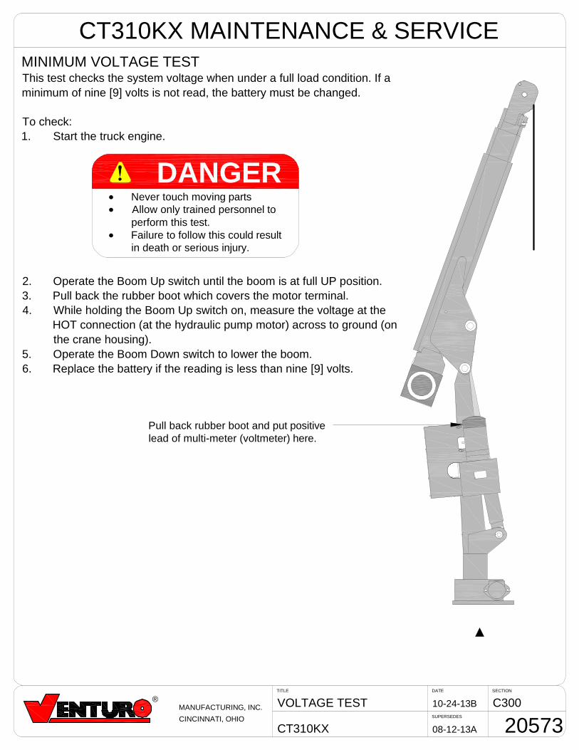
MINIMUM VOLTAGE TESTThis test checks the system voltage when under a full load condition. If aminimum of nine [9] volts is not read, the battery must be changed.
To check:1. Start the truck engine.
2. Operate the Boom Up switch until the boom is at full UP position.3. Pull back the rubber boot which covers the motor terminal.4. While holding the Boom Up switch on, measure the voltage at the
HOT connection (at the hydraulic pump motor) across to ground (onthe crane housing).
5. Operate the Boom Down switch to lower the boom.6. Replace the battery if the reading is less than nine [9] volts.
DANGERD Never touch moving partsD Allow only trained personnel to
perform this test.D Failure to follow this could result
in death or serious injury.
Pull back rubber boot and put positivelead of multi-meter (voltmeter) here.
CT310KX MAINTENANCE & SERVICE
SECTIONDATE
SUPERSEDES
TITLE
CT310KX
C30008-12-13A
11-04-02
WIRE ROPE REPLCMNT
20574
R
MANUFACTURING, INC.
CINCINNATI, OHIO
CT310KX MAINTENANCE & SERVICE
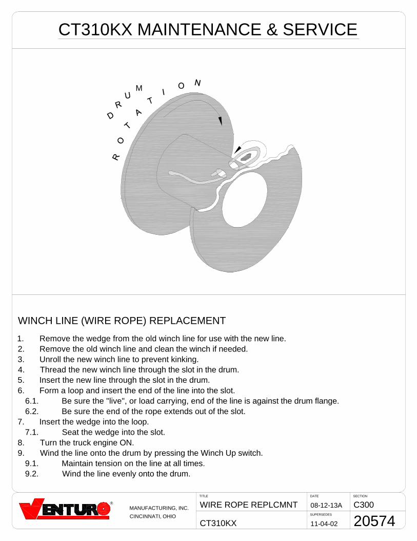
WINCH LINE (WIRE ROPE) REPLACEMENT
1. Remove the wedge from the old winch line for use with the new line.2. Remove the old winch line and clean the winch if needed.3. Unroll the new winch line to prevent kinking.4. Thread the new winch line through the slot in the drum.5. Insert the new line through the slot in the drum.6. Form a loop and insert the end of the line into the slot.
6.1. Be sure the "live", or load carrying, end of the line is against the drum flange.6.2. Be sure the end of the rope extends out of the slot.
7. Insert the wedge into the loop.7.1. Seat the wedge into the slot.
8. Turn the truck engine ON.9. Wind the line onto the drum by pressing the Winch Up switch.
9.1. Maintain tension on the line at all times.9.2. Wind the line evenly onto the drum.
M
SECTIONDATE
SUPERSEDES
TITLE
CT310KX
C30008-12-13A
11-04-02
HYDRAULIC SCHEMATIC
20575
R
MANUFACTURING, INC.
CINCINNATI, OHIO
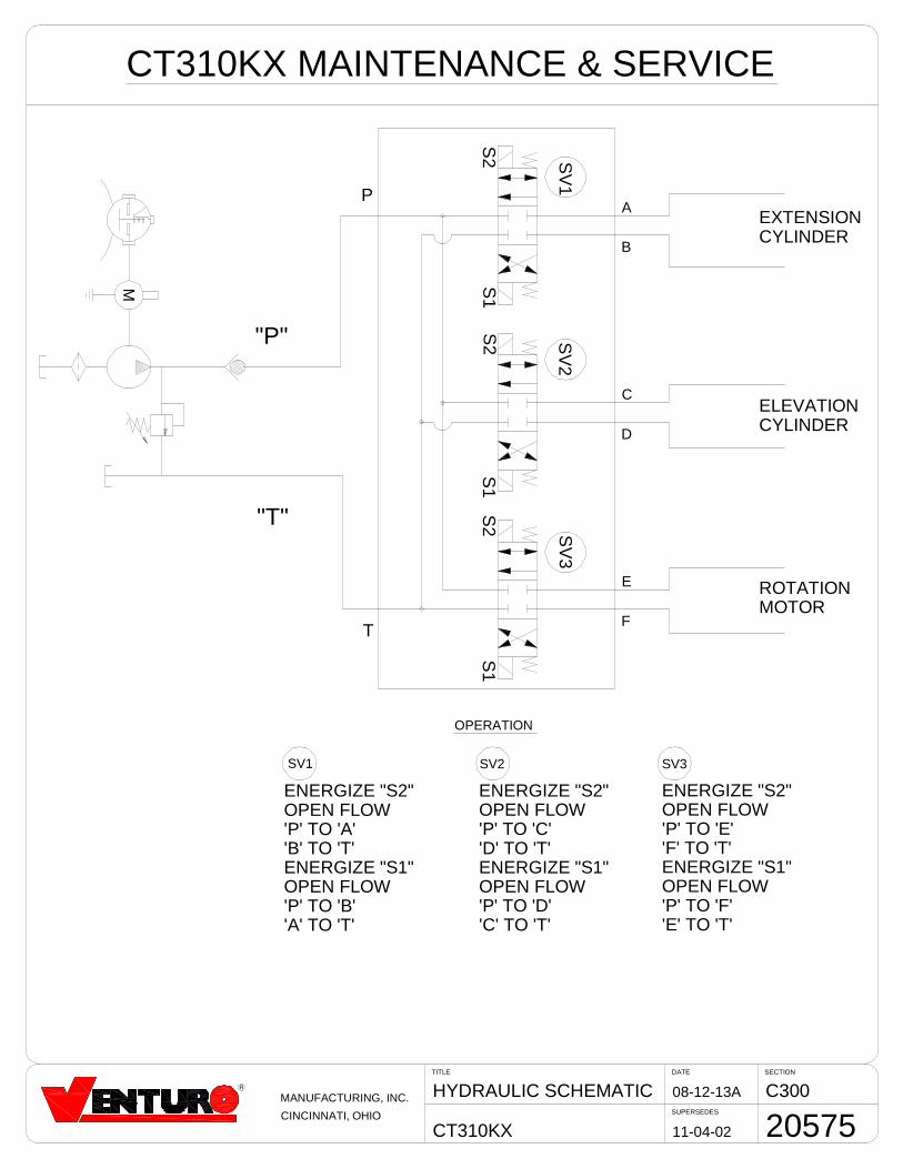
CT310KX MAINTENANCE & SERVICE
"P"
"T"
M
S2
S2
SV
1
S1
S1
S2
S1
SV
3S
V2
P
ELEVATIONCYLINDER
EXTENSIONCYLINDER
SV2
OPERATION
A
B
C
D
E
FT
SV1
ENERGIZE "S2"OPEN FLOW'P' TO 'A''B' TO 'T'ENERGIZE "S1"OPEN FLOW'P' TO 'B''A' TO 'T'
ENERGIZE "S2"OPEN FLOW'P' TO 'C''D' TO 'T'ENERGIZE "S1"OPEN FLOW'P' TO 'D''C' TO 'T'
SV3
ENERGIZE "S2"OPEN FLOW'P' TO 'E''F' TO 'T'ENERGIZE "S1"OPEN FLOW'P' TO 'F''E' TO 'T'
ROTATIONMOTOR
SECTION 400
PARTS
7607400A
RE
PLA
CE
ME
NT
PA
RT
SIL
LUS
TR
AT
ION
C40
0
CT
310K
Xw
/340
ºA
DJU
ST
AB
LER
OT
AT
ION
5-21
-14C
DA
TE
SE
CT
ION
SU
PE
RS
ED
ES
TIT
LE
2739
45-
9-14
B
®M
AN
UF
AC
TU
RIN
G,I
NC
.
CIN
CIN
NA
TI,
OH
IO
6
1
21
2322
29
27
10
13
14
12
9
11
16
15
28
2625
24
515
43
171819
20
2
7
8
RE
PLA
CE
ME
NT
PA
RT
SLI
ST
RE
F.D
WG
.273
95
35
3736
38
39
38
PR
IMA
RY
BO
OM
SE
CO
ND
AR
YB
OO
M
SE
CT
ION
-B
EA
RIN
G
SE
CT
ION
-B
EA
RIN
G
GU
IDE
PA
DS
GU
IDE
PA
DS
41
40
40
43 4442
45
3736
10
52
4647
5354
5657
32 55 33
58
59
50
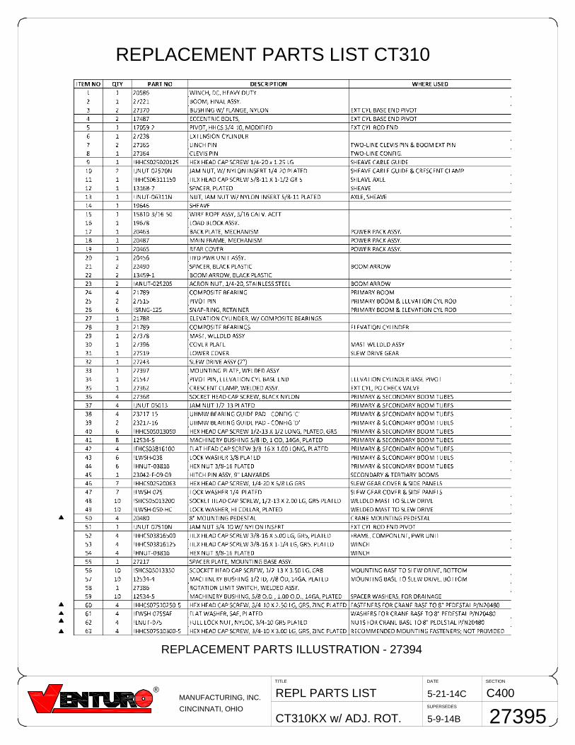
63
SECTIONDATE
SUPERSEDES
TITLE
CT310KX w/ ADJ. ROT.
C4005-21-14CREPL PARTS LIST
27395
®MANUFACTURING, INC.
CINCINNATI, OHIO
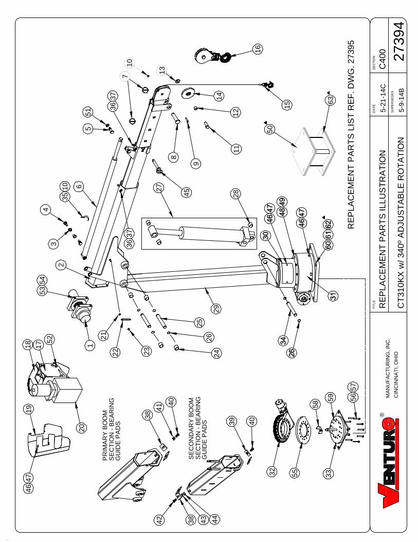
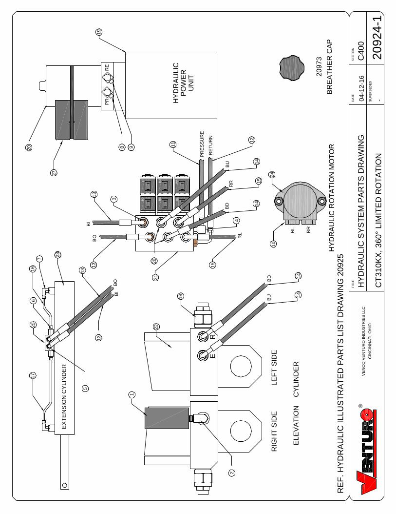
REPLACEMENT PARTS ILLUSTRATION - 27394
REPLACEMENT PARTS LIST CT310
5-9-14B
RL
BO
BI
BU
RR
RL
PR
ES
SU
RE
HY
DR
AU
LIC
RO
TA
TIO
NM
OT
OR
BD
EL
EV
AT
ION
CY
LIN
DE
R
RR
RL
RE
PR HY
DR
AU
LIC
PO
WE
RU
NIT
EX
TE
NS
ION
CY
LIN
DE
R
BI
BO
BU
BD
RR
14
15
14
12
3
13
13
21
15
11
4
BR
EA
TH
ER
CA
P
20
973
19
RE
TU
RN
RIG
HT
SID
EL
EF
TS
IDE
RE
6 BU 1
4
BD 1
4
BI
BO
1316
7
17
25
5
1
2
18
10
13
20
22
23
24
RE
F.
HY
DR
AU
LIC
ILL
US
TR
AT
ED
PA
RT
SLIS
TD
RA
WIN
G20925
26
C4
00
HY
DR
AU
LIC
SY
ST
EM
PA
RT
SD
RA
WIN
G
CT
31
0K
X,
36
0°
LIM
ITE
DR
OT
AT
ION
04-1
2-1
6
DA
TE
SE
CT
ION
SU
PE
RS
ED
ES
TIT
LE
20
92
4-1
-
®V
EN
CO
VE
NT
UR
OIN
DU
ST
RIE
SLLC
CIN
CIN
NA
TI,
OH
IO
8 9
27
NOTE: ITEMS 2 THROUGH 17 ARE INCLUDED IN THE HOSE & FITTING KIT P/N 27393.
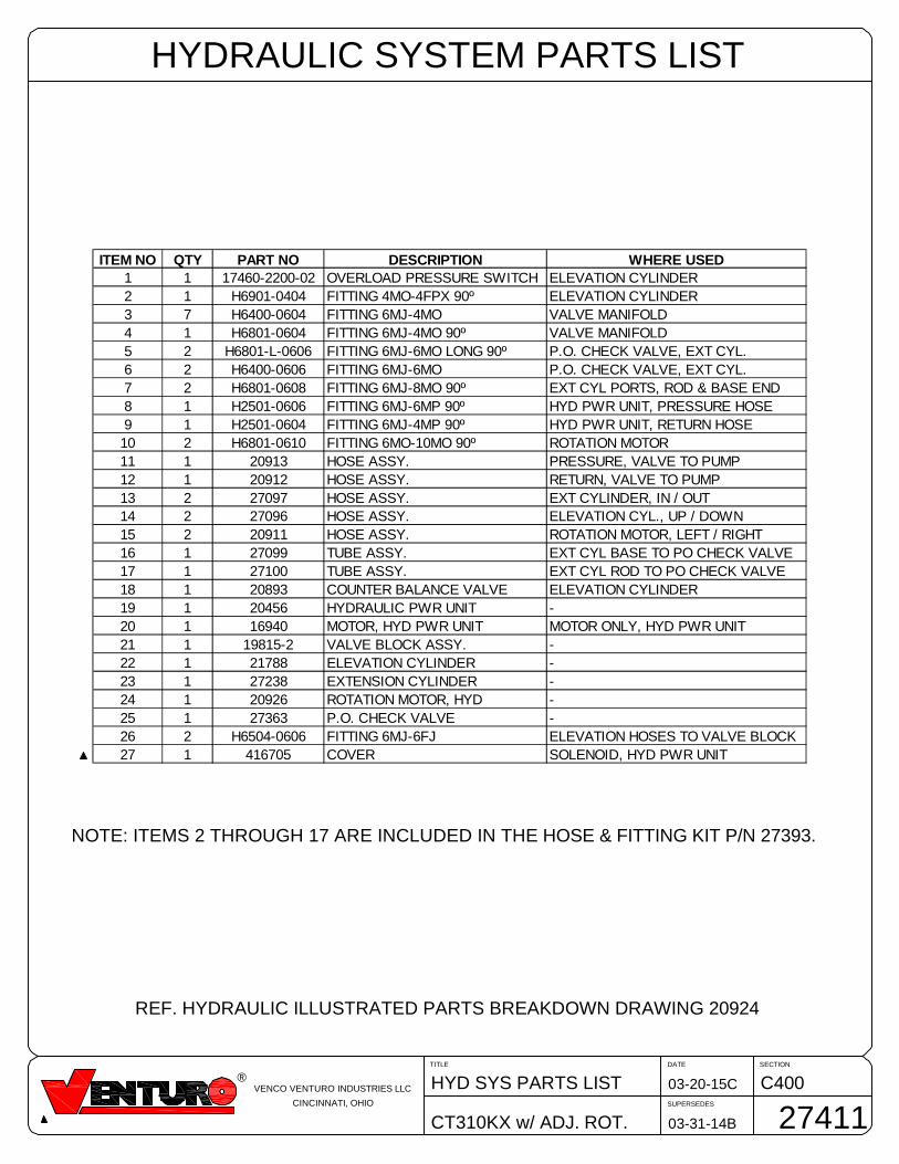
REF. HYDRAULIC ILLUSTRATED PARTS BREAKDOWN DRAWING 20924
HYDRAULIC SYSTEM PARTS LIST
SECTIONDATE
SUPERSEDES
TITLE
CT310KX w/ ADJ. ROT.
C40003-20-15C
03-31-14B
HYD SYS PARTS LIST
27411
®VENCO VENTURO INDUSTRIES LLC
CINCINNATI, OHIO
ITEM NO QTY PART NO DESCRIPTION WHERE USED1 1 17460-2200-02 OVERLOAD PRESSURE SWITCH ELEVATION CYLINDER2 1 H6901-0404 FITTING 4MO-4FPX 90º ELEVATION CYLINDER3 7 H6400-0604 FITTING 6MJ-4MO VALVE MANIFOLD4 1 H6801-0604 FITTING 6MJ-4MO 90º VALVE MANIFOLD5 2 H6801-L-0606 FITTING 6MJ-6MO LONG 90º P.O. CHECK VALVE, EXT CYL.6 2 H6400-0606 FITTING 6MJ-6MO P.O. CHECK VALVE, EXT CYL.7 2 H6801-0608 FITTING 6MJ-8MO 90º EXT CYL PORTS, ROD & BASE END8 1 H2501-0606 FITTING 6MJ-6MP 90º HYD PWR UNIT, PRESSURE HOSE9 1 H2501-0604 FITTING 6MJ-4MP 90º HYD PWR UNIT, RETURN HOSE
10 2 H6801-0610 FITTING 6MO-10MO 90º ROTATION MOTOR11 1 20913 HOSE ASSY. PRESSURE, VALVE TO PUMP12 1 20912 HOSE ASSY. RETURN, VALVE TO PUMP13 2 27097 HOSE ASSY. EXT CYLINDER, IN / OUT14 2 27096 HOSE ASSY. ELEVATION CYL., UP / DOWN15 2 20911 HOSE ASSY. ROTATION MOTOR, LEFT / RIGHT16 1 27099 TUBE ASSY. EXT CYL BASE TO PO CHECK VALVE17 1 27100 TUBE ASSY. EXT CYL ROD TO PO CHECK VALVE18 1 20893 COUNTER BALANCE VALVE ELEVATION CYLINDER19 1 20456 HYDRAULIC PWR UNIT -20 1 16940 MOTOR, HYD PWR UNIT MOTOR ONLY, HYD PWR UNIT21 1 19815-2 VALVE BLOCK ASSY. -22 1 21788 ELEVATION CYLINDER -23 1 27238 EXTENSION CYLINDER -24 1 20926 ROTATION MOTOR, HYD -25 1 27363 P.O. CHECK VALVE -26 2 H6504-0606 FITTING 6MJ-6FJ ELEVATION HOSES TO VALVE BLOCK27 1 416705 COVER SOLENOID, HYD PWR UNIT
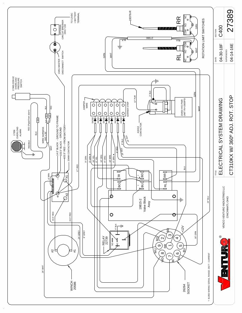
C4
00
ELE
CT
RIC
AL
SY
ST
EM
DR
AW
ING
CT
31
0K
XW
/3
60
ºA
DJ.
RO
T.S
TO
P
04-3
0-1
8F
DA
TE
SE
CT
ION
SU
PE
RS
ED
ES
TIT
LE
27389
04-1
4-1
6E
®
13451
MA
ST
ER
DIS
CO
NN
EC
TS
WIT
CH
TE
RM
INA
L
+B
AT
TE
RY
TO
12V
DC
45
6
71
3
29
8
DIO
DE
DIO
DE
DIO
DE
DIO
DE
DIO
DE
DIO
DE
17356
OV
ER
LO
AD
ALA
RM
WIR
EH
AR
NE
SS
18/2
x26"
RE
D(P
igta
ilfr
om
ala
rm)
WH
T
BLK
BLK
MF
BLK
24"
WH
T
9"
GR
N
9"
GR
N
18
"Y
EL
8"
YE
L
18
"O
RG
8"
OR
G
18
"B
RN
8"
BR
N
8"
RE
D
8"
BLK
18"
RE
D
18"
BLK
3"
BLK
12
"P
UR
198
15
-2
Valv
eB
lock
Ass
y
262
64
SO
CK
ET
WD
WU
BO
BD
+12V
BU
RL
BI
RR
18
"G
RN
BO
BI
BU
BD
RL
RR
24
"B
LU
BA
RR
IER
ST
RIP
5"
BLK
JU
MP
ER
WIR
E
WH
T
RE
D/B
LK
+
4"
BR
N
20499
CO
NT
AC
TO
R
24
"G
RE
Y
8"
GR
EY
RE
D4
3.5
"R
ED
43
.5"
RE
D
17
"R
ED
RE
LA
Y2
27
39
WIN
CH
BLK
-
NO
NC
416310
CO
NT
AC
TO
R
#2
#1
#1
#2
17460-2
200-0
2O
VE
RLO
AD
PR
ES
SU
RE
SW
ITC
H
OP
TIO
NA
L
19417-1
50
CIR
CU
ITB
RE
AK
ER
205
86
20456
HY
DP
WR
UN
ITR
V=
2600P
SI
CO
MC
OM
NO
NC
NO
NC
RO
TA
TIO
NLIM
ITS
WIT
CH
ES
BLK
WH
TG
RN
RR
RL
BLK
WH
T
WH
T
GR
N
GR
N
27390
19
37
6-R
14.0
"B
LA
CK
103
.5"
BL
AC
K
103
.5"
RE
D
-G
RO
UN
DT
OF
RA
ME
-G
RO
UN
D
+F
RO
MB
AT
TE
RY
MF M
F
VE
NC
OV
EN
TU
RO
IND
US
TR
IES
LLC
CIN
CIN
NA
TI,
OH
IO
††
†B
U/B
DW
IRIN
GS
ER
IAL
RA
NG
E:29177
-C
UR
RE
NT
-R
EP
LAC
EM
EN
TP
AR
TS
DR
AW
ING
CT
310K
X&
ET
6K
01-2
6-15
D
DA
TE
SE
CT
ION
SU
PE
RS
ED
ES
TIT
LE
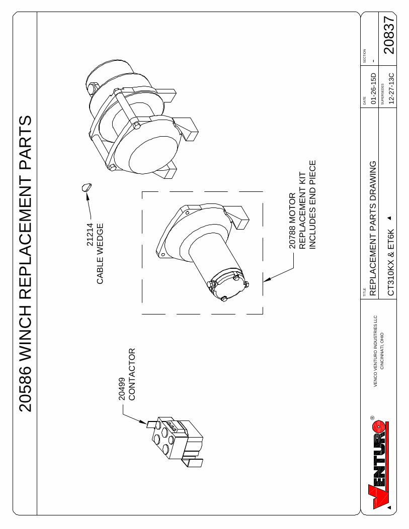
2083
712
-27-
13C
2078
8M
OT
OR
RE
PLA
CE
ME
NT
KIT
INC
LUD
ES
EN
DP
IEC
E
2049
9C
ON
TA
CT
OR
2121
4C
AB
LEW
ED
GE
2058
6W
INC
HR
EP
LAC
EM
EN
TP
AR
TS
®V
EN
CO
VE
NT
UR
OIN
DU
ST
RIE
SLL
C
CIN
CIN
NA
TI,
OH
IO
C40
0S
LEW
ING
SY
ST
EM
RE
PLA
CE
ME
NT
PA
RT
S
CT
310K
X&
ET
6K
01-2
6-15
A
DA
TE
SE
CT
ION
SU
PE
RS
ED
ES
TIT
LE
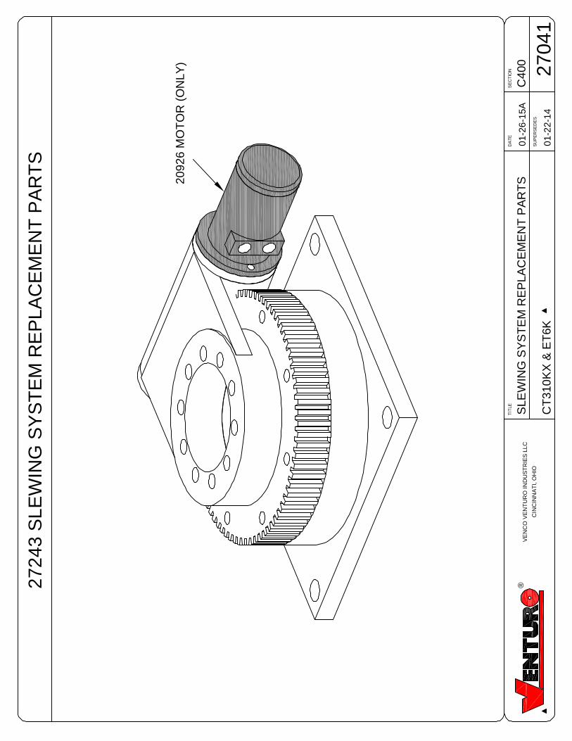
2704
101
-22-
14
2092
6M
OT
OR
(ON
LY)
2724
3S
LEW
ING
SY
ST
EM
RE
PLA
CE
ME
NT
PA
RT
S
®V
EN
CO
VE
NT
UR
OIN
DU
ST
RIE
SLL
C
CIN
CIN
NA
TI,
OH
IO
CO
NT
RO
LP
EN
DA
NT
PA
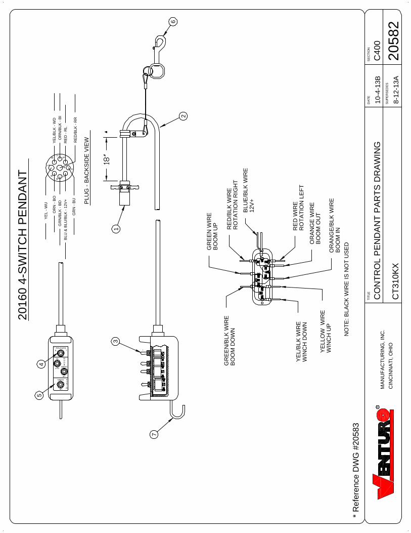
RT
SD
RA
WIN
GC
400
CT
310K
X
10-4
-13B
DA
TE
SE
CT
ION
SU
PE
RS
ED
ES
TIT
LE
2058
28-
12-1
3A
R
MA
NU
FA
CT
UR
ING
,IN
C.
CIN
CIN
NA
TI,
OH
IO
*R
efer
ence
DW
G#2
0583
2
3
7
6
54
1
OR
N/B
LK-
BI
RE
D-
RL
RE
D/B
LK-
RR
OR
N-
BO
PLU
G-
BA
CK
SID
EV
IEW
YE
L-
WU
GR
N/B
LK-
BD
GR
N-
BU
YE
L/B
LK-
WD
BLU
&B
LU/B
LK-
12V
+
NO
TE
:BLA
CK
WIR
EIS
NO
TU
SE
D
WINCH
BOOM
ROTATIONLR
UP
DOWN
IN
OUT
DOWN
UP
8
7
54
3
6
91
2
2016
04-
SW
ITC
HP
EN
DA
NT
OR
AN
GE
/BLK
WIR
EB
OO
MIN
OR
AN
GE
WIR
EB
OO
MO
UT
RE
DW
IRE
RO
TA
TIO
NLE
FT
RE
D/B
LKW
IRE
RO
TA
TIO
NR
IGH
T
GR
EE
N/B
LKW
IRE
BO
OM
DO
WN
YE
L/B
LKW
IRE
WIN
CH
DO
WN
YE
LLO
WW
IRE
WIN
CH
UP
GR
EE
NW
IRE
BO
OM
UP
BLU
E/B
LKW
IRE
12V
+
SECTIONDATE
SUPERSEDES
TITLE
CT310KX
C40008-12-13A
11-04-02
CNTRL PNDNT PRTS LIST
20583
R
MANUFACTURING, INC.
CINCINNATI, OHIO
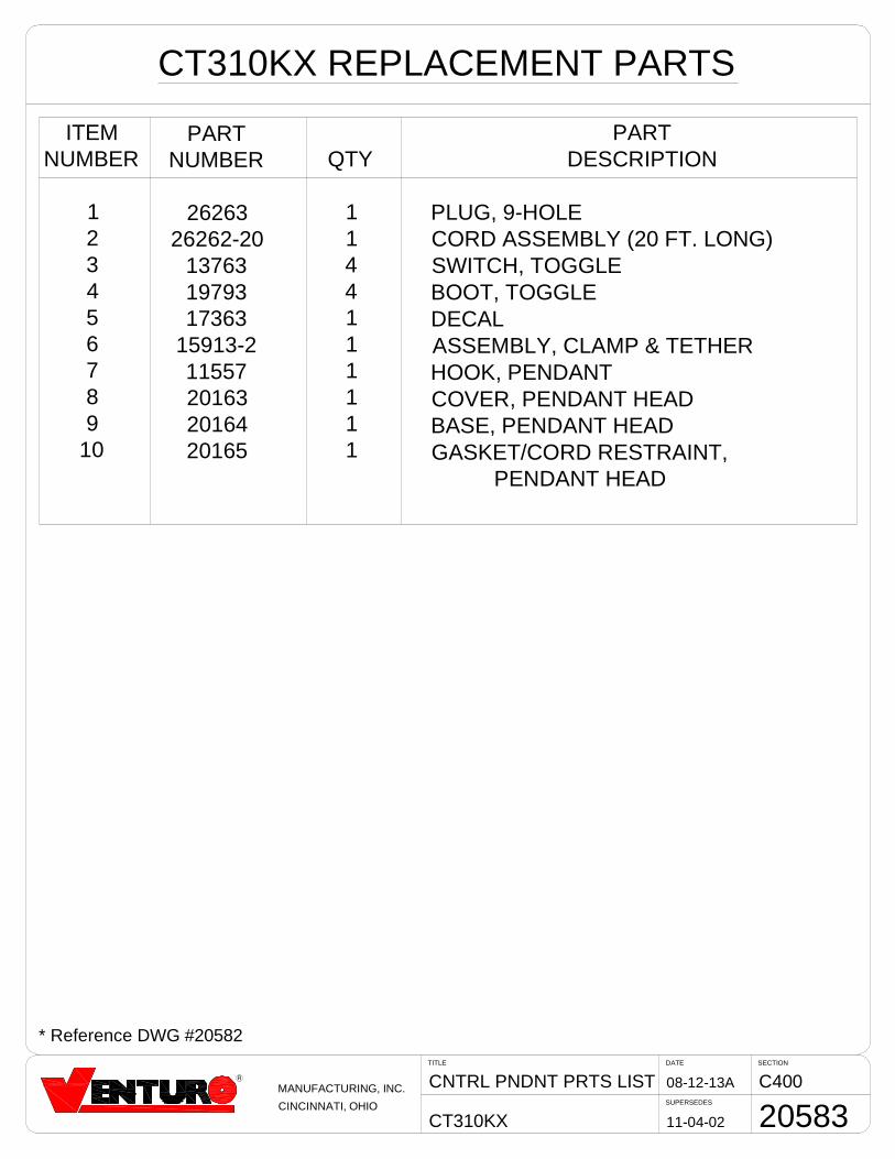
CT310KX REPLACEMENT PARTS
ITEMNUMBER
123456789
10
* Reference DWG #20582
PARTNUMBER
2626326262-20
137631979317363
15913-211557201632016420165
QTY
1144111111
PARTDESCRIPTION
PLUG, 9-HOLECORD ASSEMBLY (20 FT. LONG)SWITCH, TOGGLEBOOT, TOGGLEDECALASSEMBLY, CLAMP & TETHERHOOK, PENDANTCOVER, PENDANT HEADBASE, PENDANT HEADGASKET/CORD RESTRAINT,
PENDANT HEAD
VENCO VENTURO INDUSTRIES LLC
CINCINNATI, OHIO
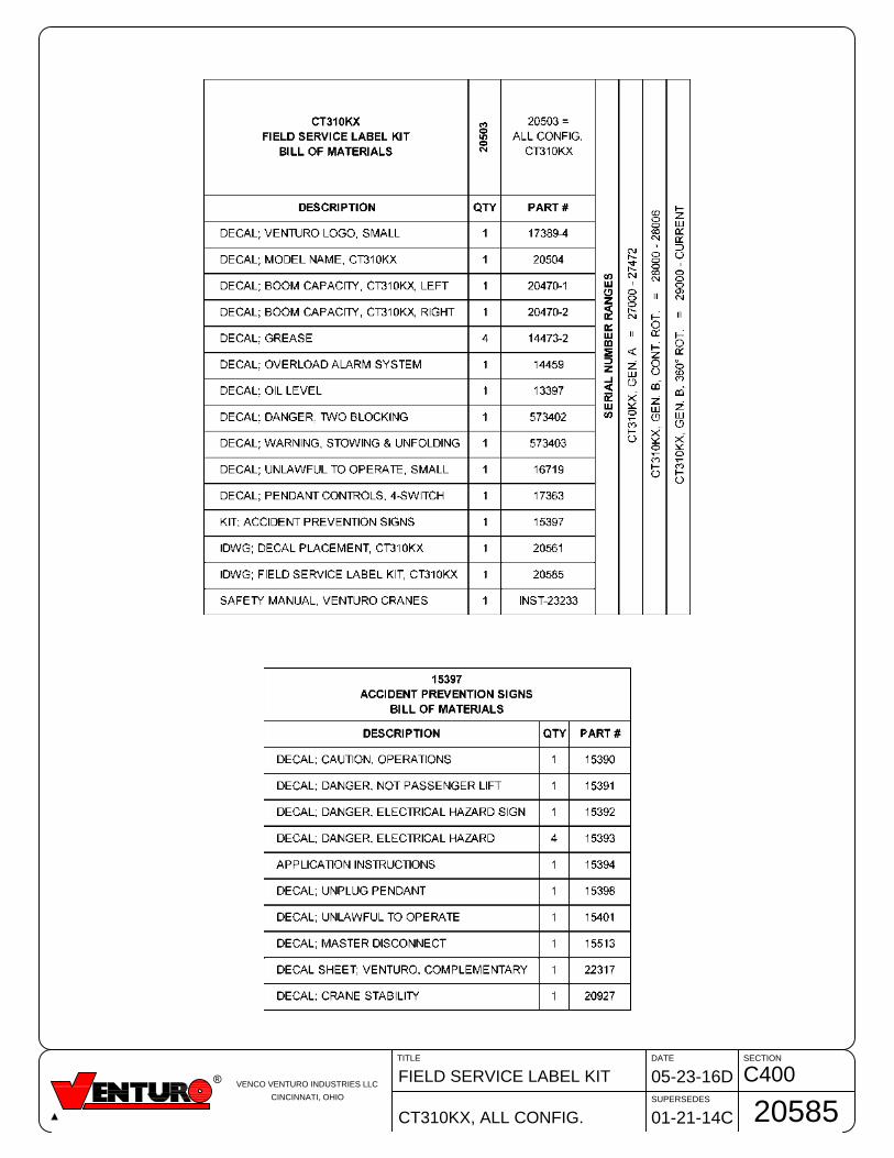
C400FIELD SERVICE LABEL KIT
CT310KX, ALL CONFIG.
05-23-16D
DATE SECTION
SUPERSEDES
TITLE
01-21-14C
20585

Revised: January 2015 12-00073_VNT1-D
VENTURO CRANES LIMITED WARRANTY POLICY Venturo products are built to last…we guarantee them. As a purchaser of any new Venturo product covered by warranty, you will receive 1 year of the most complete coverage available…and, at no added cost to you.
1-Year Limited Warranty Policy
This limited policy warrants new products of Venturo to be free from defects in material and workmanship for a period
of one (1) year from date of original installation. OEM products or accessories purchased by Venturo as part of or
offered with our product will carry the OEM manufacturer’s respective warranty. Our warranty covers:
Repair or replacement of product
Labor to repair or replace product
Freight to return and/or replace product
We shall not be liable for any contingent liabilities arising out of the improper function of any products. Warranty shall
become void if the product is improperly installed, modified, damaged, abused or used for application other than
intended use. There is no warranty of merchantability, fitness for a particular purpose, warranty arising from course of
dealing or usage of trade, or any other implied or expressed warranty, except as made specifically herein. This warranty
supersedes all previous warranties, written or implied.
Warranty Claims
Venco Venturo Industries LLC will make a good faith effort for prompt correction or other adjustment with respect to any product, which proves to be defective after our inspection and within the warranty period. Before any repairs are attempted or before returning any product, your Venturo Distributor is required to obtain a warranty claim number. This number is necessary for any claim to be considered. To obtain a warranty claim number, Venturo requires the model and serial number. Only authorized Venturo Distributors can perform warranty. For the name and address of your local Venturo Distributor call the Warranty Claim Department - 513-772-8448. WARNING - It is the responsibility of the installer to ensure the installation is completed according to the manufacturer's recommendations, ensure the ultimate user understands how to operate product in a safe manner, and understands the need for regular service and maintenance by an authorized Venturo Distributor. No modifications or alterations may be made to any Venturo product without the expressed written consent of Venco Venturo Industries LLC. Installation of any Venturo product must be done by an authorized Venturo Distributor, to the standards of the industry; including maintenance, service and affixing of all instruction, safety and warning decals. Users should be instructed as to the safe operation at time of delivery. Maintenance, service, operation and safety warning decals are available on request from Venco Venturo Industries LLC.
VENCO VENTURO INDUSTRIES LLC 12110 BEST PLACE | CINCINNATI, OHIO 45241
P: 800-226-2238 | F: 513-326-5427 www.venturo.com