Embed Size (px)
Citation preview
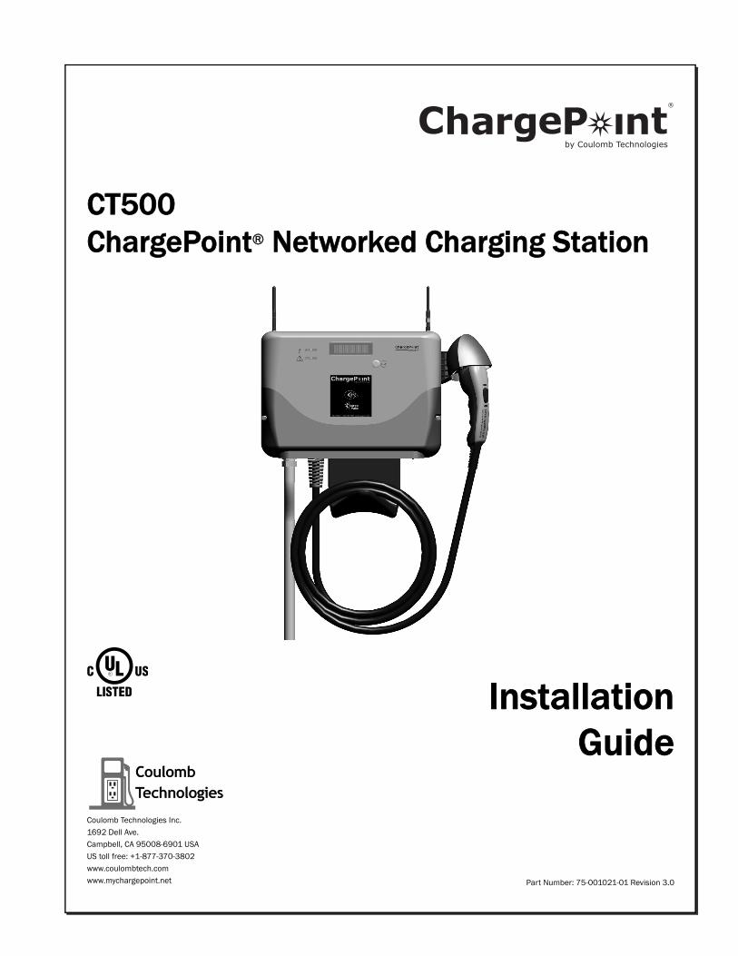
CT500 ChargePoint® Networked Charging Station
InstallationGuide
Part Number: 75-001021-01 Revision 3.0
Coulomb Technologies Inc.
1692 Dell Ave.
Campbell, CA 95008-6901 USA
US toll free: +1-877-370-3802
www.coulombtech.com
www.mychargepoint.net
by Coulomb Technologies
®
Safety and complianceThis document provides instructions to install the ChargePoint® Charging Station and should not be used for any other product. Before installing the ChargePoint® Charging Station, you should review this manual carefully and consult with a licensed contractor, licensed electrician and trained installation expert to ensure compliance with local building practices, climate conditions, safety standards, and state and local codes.The ChargePoint® Charging Station should be installed only by a licensed contractor and a licensed electrician and in accordance with all local and national codes and standards. The ChargePoint® Charging Station should be inspected by a qualified installer prior to the initial use. Under no circumstances will compliance with the information in this manual relieve the user of his/her responsibility to comply with all applicable codes or safety standards. This document describes the most commonly-used installation and mounting scenarios. If situations arise in which it is not possible to perform an installation following the procedures provided in this document, contact Coulomb Technologies. Coulomb Technologies is not responsible for any damages that may occur resulting from custom installations that are not described in this document.
No accuracy guaranteeReasonable effort was made to ensure that the specifications and other information in this manual are accurate and complete at the time of its publication. However, the specifications and other information in this manual are subject to change at any time without prior notice.
Warranty information and disclaimerYour use of, or modification to, the ChargePoint® Charging Station in a manner in which the ChargePoint® Charging Station is not intended to be used or modified will void the limited warranty. Other than any such limited warranty, the Coulomb products are provided “AS IS,” and Coulomb and its distributors expressly disclaim all implied warranties, including any warranty of design, merchantability, fitness for a particular purposes and non-infringement, to the maximum extent permitted by law.
Limitation of liabilityIN NO EVENT SHALL COULOMB TECHNOLOGIES, INC. OR ITS AUTHORIZED DISTRIBUTORS BE LIABLE FOR ANY INDIRECT, INCIDENTAL, SPECIAL, PUNITIVE, OR CONSEQUENTIAL DAMAGES, INCLUDING WITHOUT LIMITATION, LOST PROFITS, LOST DATA, LOSS OF USE, COST OF COVER, OR LOSS OR DAMAGE TO THE CHARGEPOINT® CHARGING STATION, ARISING OUT OF OR RELATING TO THE USE OR INABILITY TO USE THIS MANUAL, EVEN IF COULOMB TECHNOLOGIES, INC. OR ITS AUTHORIZED DISTRIBUTORS HAVE BEEN ADVISED OF THE POSSIBILITY OF SUCH DAMAGES.
Copyright and trademarks©2010-2011 Coulomb Technologies, Inc. All rights reserved. This material is protected by the copyright laws of the United States and other countries. It may not be modified, reproduced or distributed without the prior, express written consent of Coulomb Technologies, Inc. CHARGEPOINT is a U.S. registered trademark and service mark of Coulomb Technologies, Inc. All other products or services mentioned are the trademarks, service marks, registered trademarks or registered service marks of their respective owners. Coulomb Technologies has filed several patent applications.
IMPORTANT SAFETY INSTRUCTIONS
This Installation Guide contains important instructions that must be followed when installing the CT500.
Warnings:
• The CT500 must be connected to a grounded, metal, permanent wiring system; or an equipment grounding conductor must be run with the circuit conductors and connected to the CT500’s grounding terminal or lead.
• The CT500 must be installed by a qualified electrician and in accordance with all local electrical codes and ordinances.
• Read all instructions before installing the CT500.
• Adult supervision is required when using the CT500 near children.
• Do not operate a CT500 with a visibly damaged cable. Contact Coulomb Technologies immediately.
• Do not operate a CT500 if the enclosure or the EV connector is broken, cracked, open, or shows any other signs of damage. Contact Coulomb Technologies immediately.
• Do not put fingers into the EV connector.
• Do not install the CT500 near flammable, explosive, or combustible materials.
• Do not operate the CT500 in temperatures outside its operating range of -22°F to 122°F (-30°C to +50°C).
• The CT500 contains no user-serviceable parts. Do not attempt to repair or service the CT500 yourself. If the CT500 requires servicing, contact Coulomb Technologies.
• Ensure that the CT500’s charging cable is positioned so it will not be stepped on, tripped over, or subjected to damage or stress.
SAVE THESE INSTRUCTIONS
Cleaning the CT500
Do not use cleaning solvents to clean any of the CT500’s components. The outside of the CT500, the charging cable, and the connector end of the charging cable should be regularly wiped with a clean dry cloth to remove any accumulation of dust and dirt.
FCC Declaration of Conformity
This device complies with Part 15 of the FCC rules. Operation is subject to the following two conditions: (1) This device may not cause harmful interference, and (2) this device must accept any interference received, including interference that may cause undesired operation.
Radio and Television Interference
The equipment described in this manual has been designed to protect against Radio Frequency Interference (RFI). However, there are some instances where high powered radio signals or nearby RF-producing equipment (such as digital phones, RF communications equipment, etc.) could affect operations.
If interference to your CT500 is suspected, relocate or turn off nearby electrical appliances during charging, before contacting Coulomb Technologies for assistance.
Important!
Changes or modifications to this product not authorized by Coulomb Technologies could void the FCC compliance.
At the end of its service life, this product should be recycled according to local laws and regulations. Contact Coulomb Technologies for recycling information.

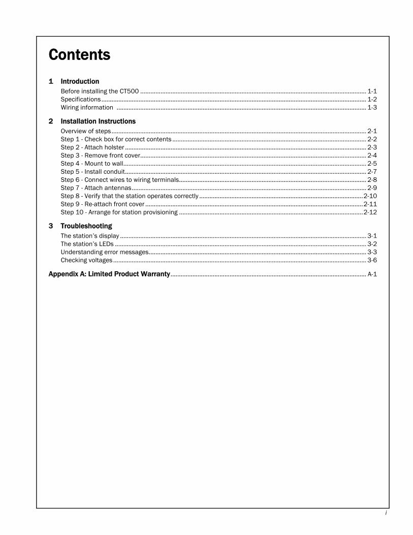
Contents
1 IntroductionBefore installing the CT500 ...................................................................................................................................... 1-1Specifications............................................................................................................................................................. 1-2Wiring information .................................................................................................................................................... 1-3
2 Installation InstructionsOverview of steps....................................................................................................................................................... 2-1Step 1 - Check box for correct contents ................................................................................................................... 2-2Step 2 - Attach holster ............................................................................................................................................... 2-3Step 3 - Remove front cover...................................................................................................................................... 2-4Step 4 - Mount to wall................................................................................................................................................ 2-5Step 5 - Install conduit............................................................................................................................................... 2-7Step 6 - Connect wires to wiring terminals............................................................................................................... 2-8Step 7 - Attach antennas........................................................................................................................................... 2-9Step 8 - Verify that the station operates correctly .................................................................................................2-10Step 9 - Re-attach front cover .................................................................................................................................2-11Step 10 - Arrange for station provisioning .............................................................................................................2-12
3 TroubleshootingThe station’s display .................................................................................................................................................. 3-1The station’s LEDs ..................................................................................................................................................... 3-2Understanding error messages................................................................................................................................. 3-3Checking voltages ...................................................................................................................................................... 3-6
Appendix A: Limited Product Warranty.................................................................................................................... A-1
i

Introduction 1
This document provides step-by-step instructions on how to install any CT500 ChargePoint® Charging Station.Before installing the CT500• Ensure that the appropriate wiring, circuit protection, and metering is in place at the installation
location. For details, refer to the specifications (page 1-2) and wiring diagrams (page 1-3).
• Ensure that the type of modem in the CT500 station that you are installing is compatible with the type of modem coverage available at the installation site (CDMA or GPRS).
• Disconnect power.
• Determine the appropriate mounting location for the CT500. The CT500 is designed to be secured to a masonry wall or a hollow wall with wood studs 16” apart. If this is not the case, prepare an appropriate mounting surface.
• Familiarize yourself with the installation procedure by thoroughly reviewing Chapter 2 “Installation Instructions.”
1-1
ChargePoint® Charging Stations
1-2
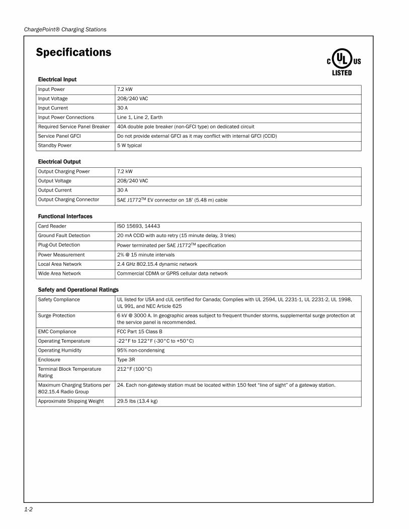
Specifications
Electrical Input
Input Power 7.2 kW
Input Voltage 208/240 VAC
Input Current 30 A
Input Power Connections Line 1, Line 2, Earth
Required Service Panel Breaker 40A double pole breaker (non-GFCI type) on dedicated circuit
Service Panel GFCI Do not provide external GFCI as it may conflict with internal GFCI (CCID)
Standby Power 5 W typical
Electrical Output
Output Charging Power 7.2 kW
Output Voltage 208/240 VAC
Output Current 30 A
Output Charging Connector SAE J1772TM EV connector on 18’ (5.48 m) cable
Functional Interfaces
Card Reader ISO 15693, 14443
Ground Fault Detection 20 mA CCID with auto retry (15 minute delay, 3 tries)
Plug-Out Detection Power terminated per SAE J1772TM specification
Power Measurement 2% @ 15 minute intervals
Local Area Network 2.4 GHz 802.15.4 dynamic network
Wide Area Network Commercial CDMA or GPRS cellular data network
Safety and Operational Ratings
Safety Compliance UL listed for USA and cUL certified for Canada; Complies with UL 2594, UL 2231-1, UL 2231-2, UL 1998, UL 991, and NEC Article 625
Surge Protection 6 kV @ 3000 A. In geographic areas subject to frequent thunder storms, supplemental surge protection at the service panel is recommended.
EMC Compliance FCC Part 15 Class B
Operating Temperature -22°F to 122°F (-30°C to +50°C)
Operating Humidity 95% non-condensing
Enclosure Type 3R
Terminal Block TemperatureRating
212°F (100°C)
Maximum Charging Stations per 802.15.4 Radio Group
24. Each non-gateway station must be located within 150 feet “line of sight” of a gateway station.
Approximate Shipping Weight 29.5 lbs (13.4 kg)
Introduction
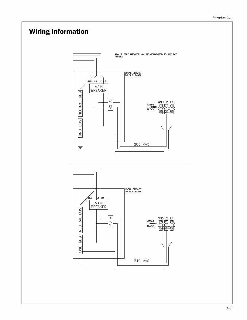
Wiring information
1-3

Installation Instructions 2
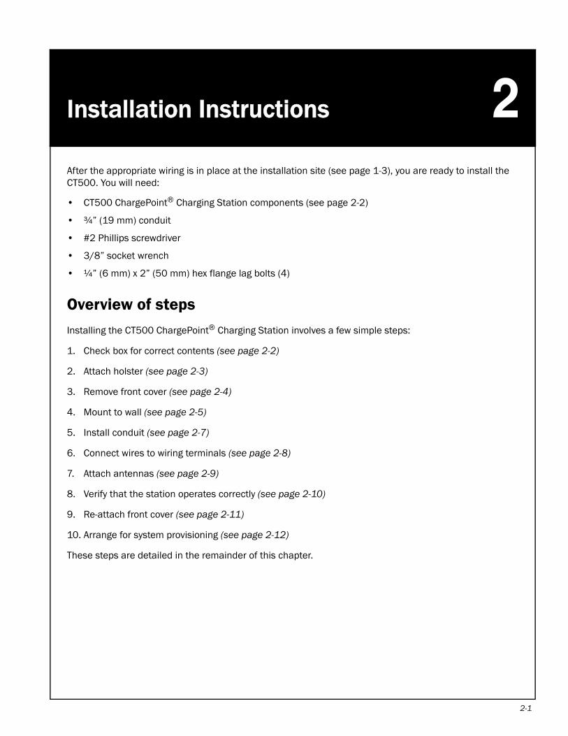
After the appropriate wiring is in place at the installation site (see page 1-3), you are ready to install the CT500. You will need:• CT500 ChargePoint® Charging Station components (see page 2-2)
• ¾” (19 mm) conduit
• #2 Phillips screwdriver
• 3/8” socket wrench
• ¼” (6 mm) x 2” (50 mm) hex flange lag bolts (4)
Overview of steps
Installing the CT500 ChargePoint® Charging Station involves a few simple steps:
1. Check box for correct contents (see page 2-2)
2. Attach holster (see page 2-3)
3. Remove front cover (see page 2-4)
4. Mount to wall (see page 2-5)
5. Install conduit (see page 2-7)
6. Connect wires to wiring terminals (see page 2-8)
7. Attach antennas (see page 2-9)
8. Verify that the station operates correctly (see page 2-10)
9. Re-attach front cover (see page 2-11)
10. Arrange for system provisioning (see page 2-12)
These steps are detailed in the remainder of this chapter.
2-1

ChargePoint® Charging Stations
2-2
Step 1 - Check box for correct contents
The CT500 ChargePoint® Charging Station ships in a box containing:
• Main assembly
• Holster
• Holster bolts (3)
• Antenna(s)*
• Mounting template
• Installation Guide
• Spare provisioning label (a duplicate label has been attached to the main assembly).
IMPORTANT: Keep the spare provisioning label for future reference. It contains critical information that is needed for system provisioning (see page 2-12).
*The CT500 ships with either one or two antennas, depending on the specific model that was ordered.
CT500 ChargePoint® Networked Charging Station
InstallationGuide
Part Number: 75-001024-01 Revision: 1.0
Coulomb Technologies Inc.1692 Dell Ave.Campbell, CA 95008-6901 USAUS toll free: +1-877-370-3802www.coulombtech.comwww.mychargepoint.net
by Coulomb Technologies
®
Coulomb Technologies, Inc.Order Desc.: CTXXX-zzzzzzzzzzzzzzzzSerial No: YYWWSSnnnnnn
(MAC 0000:0000:0000:0000)Provisioning Password 00000
Illustration only (not to scale):
Holster bolts (3)Main assembly
Holster
Antenna(s)
Spare provisioning label
Installation Instructions
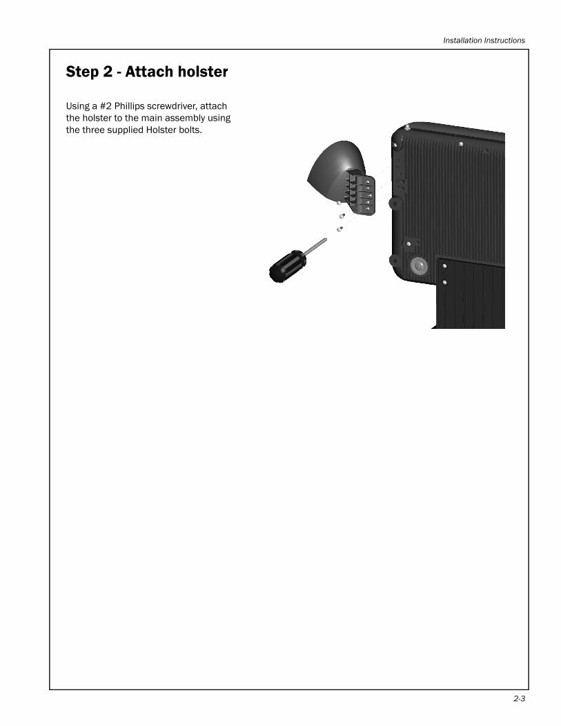
Step 2 - Attach holster
Using a #2 Phillips screwdriver, attach the holster to the main assembly using the three supplied Holster bolts.
2-3
ChargePoint® Charging Stations
2-4
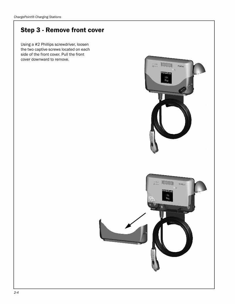
Step 3 - Remove front cover
Using a #2 Phillips screwdriver, loosen the two captive screws located on each side of the front cover. Pull the front cover downward to remove.
Installation Instructions
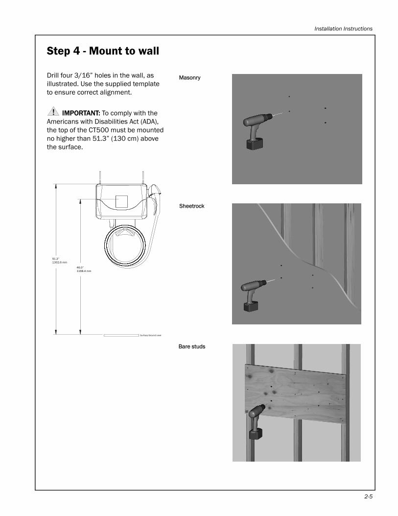
Step 4 - Mount to wall
Drill four 3/16” holes in the wall, as illustrated. Use the supplied template to ensure correct alignment.
IMPORTANT: To comply with the Americans with Disabilities Act (ADA), the top of the CT500 must be mounted no higher than 51.3” (130 cm) above the surface.
Masonry
Sheetrock
Bare studs
51.3”1302.6 mm
46.0”1168.4 mm
Surface/Ground Level
2-5
ChargePoint® Charging Stations
2-6
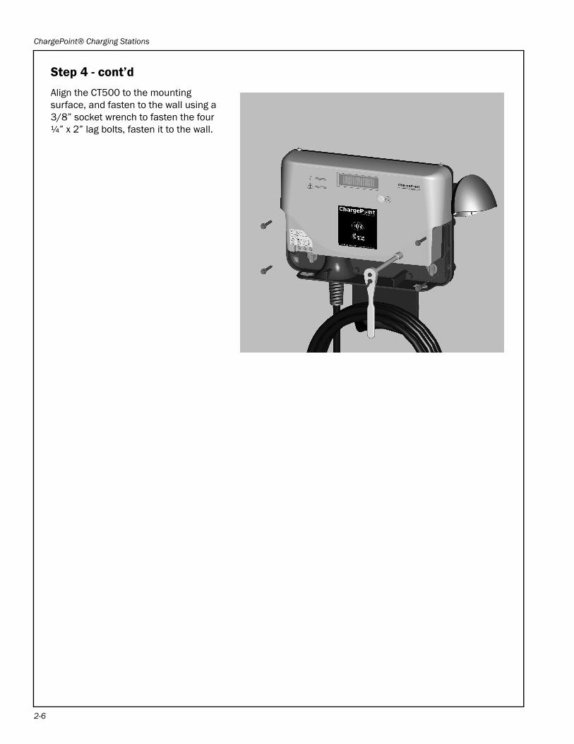
Step 4 - cont’d
Align the CT500 to the mounting surface, and fasten to the wall using a 3/8” socket wrench to fasten the four ¼” x 2” lag bolts, fasten it to the wall.
Installation Instructions
Step 5 - Install conduit
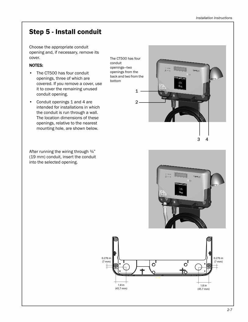
Choose the appropriate conduit opening and, if necessary, remove its cover.
NOTES:
• The CT500 has four conduit openings, three of which are covered. If you remove a cover, use it to cover the remaining unused conduit opening.
• Conduit openings 1 and 4 are intended for installations in which the conduit is run through a wall. The location dimensions of these openings, relative to the nearest mounting hole, are shown below.
After running the wiring through ¾” (19 mm) conduit, insert the conduit into the selected opening.
The CT500 has four conduit openings—two openings from the back and two from the bottom
1
2
3 4
SCALE 1.000
1.8 in(45.7 mm)
0.276 in(7 mm)
0.276 in(7 mm)
1.8 in(45.7 mm)
2-7
ChargePoint® Charging Stations
2-8
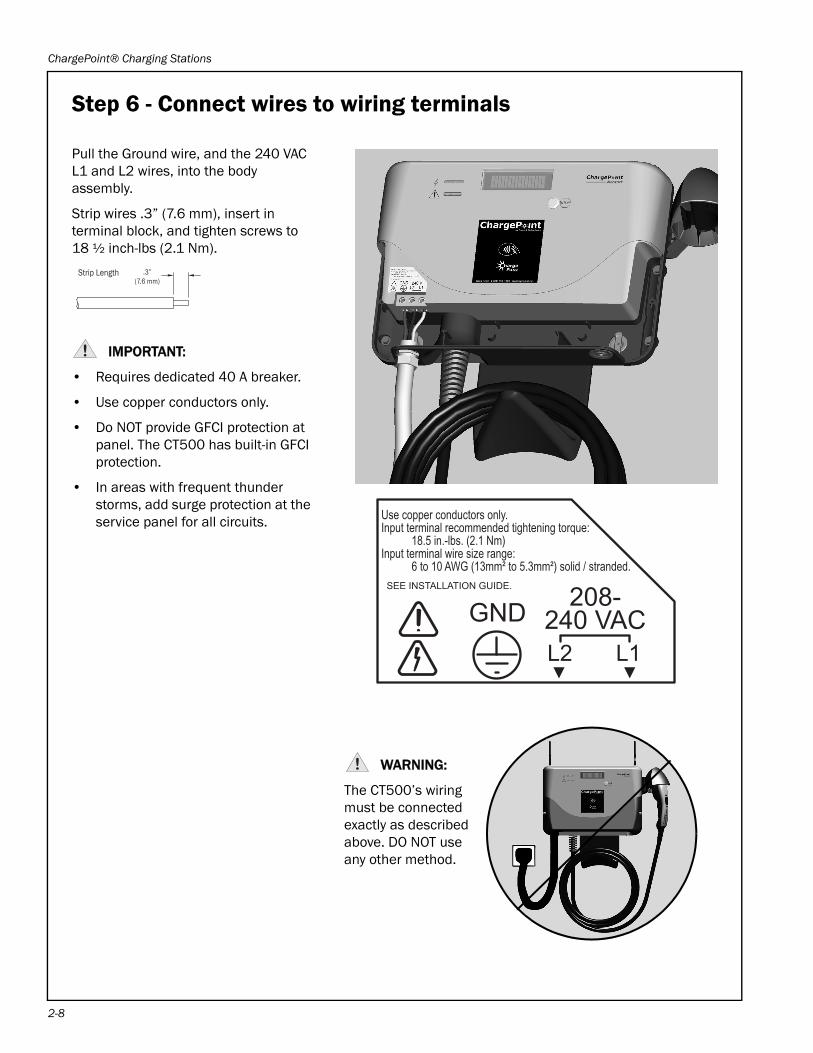
Step 6 - Connect wires to wiring terminals
Pull the Ground wire, and the 240 VAC L1 and L2 wires, into the body assembly.
Strip wires .3” (7.6 mm), insert in terminal block, and tighten screws to 18 ½ inch-lbs (2.1 Nm).
IMPORTANT:
• Requires dedicated 40 A breaker.
• Use copper conductors only.
• Do NOT provide GFCI protection at panel. The CT500 has built-in GFCI protection.
• In areas with frequent thunder storms, add surge protection at the service panel for all circuits.
WARNING:
The CT500’s wiring must be connected exactly as described above. DO NOT use any other method.
GNDL1L2
208-240 VAC
SEE INSTALLATION GUIDE.
Use copper conductors only.Input terminal recommended tightening torque: 18.5 in.-lbs. (2.1 Nm)Input terminal wire size range: 6 to 10 AWG (13mm² to 5.3mm²) solid / stranded.
� �
Strip Length .3”(7.6 mm)
Installation Instructions
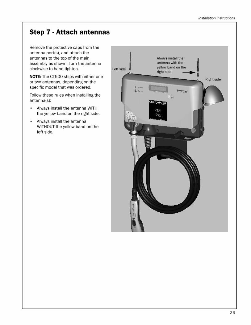
Step 7 - Attach antennas
Remove the protective caps from the antenna port(s), and attach the antennas to the top of the main assembly as shown. Turn the antenna clockwise to hand-tighten.
NOTE: The CT500 ships with either one or two antennas, depending on the specific model that was ordered.
Follow these rules when installing the antenna(s):
• Always install the antenna WITH the yellow band on the right side.
• Always install the antenna WITHOUT the yellow band on the left side.
Always install the antenna with the yellow band on the right side
Right side
Left side
2-9
ChargePoint® Charging Stations
2-1
Step 8 - Verify that the station operates correctly
Follow these instructions to ensure that the charging station is fully operational:
• Turn on the main power to ensure that the station powers up. The station will illuminate its green LED, display a series of power-up messages, then display a message indicating that it is available for charging. If this is not the case, check that the wiring is properly connected (see page 2-8) and the voltage measurements are as expected (see page 3-6).
• Ensure that the red LED on the left side of the station’s display is not illuminated or blinking. If it is, this indicates that the station has detected an error. Refer to “Chapter 3: Troubleshooting”.
• If equipped with a card reader, briefly tap a valid and authorized ChargePassTM card on the station’s front label. After authorizing the card, the CT500 should display a message indicating that it is ready to charge.
• If possible, plug the connector into an electric vehicle and ensure the station’s green LED is flashing to indicate that the vehicle is charging.
If the station does not operate as described above, refer to “Chapter 3: Troubleshooting” before contacting Coulomb Customer Support at 1-888-758-4389.
0
Installation Instructions
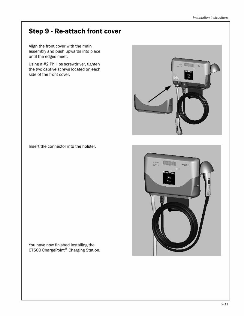
Step 9 - Re-attach front cover
Align the front cover with the main assembly and push upwards into place until the edges meet.
Using a #2 Phillips screwdriver, tighten the two captive screws located on each side of the front cover.
Insert the connector into the holster.
You have now finished installing the CT500 ChargePoint® Charging Station.
2-11
ChargePoint® Charging Stations
2-1
Step 10 - Arrange for station provisioning
After a charging station has been physically installed, it is ready to be provisioned. Provisioning is the act of connecting the charging station to the ChargePointTM network and establishing its network identity. In other words, you provision a station to “go live” on the network.
To ensure the charging station is provisioned, provide your Coulomb distributor with the following information:
• Model number
• Serial number
• MAC address
• Provisioning password
• Location information (mailing address, and if possible, exact coordinates)
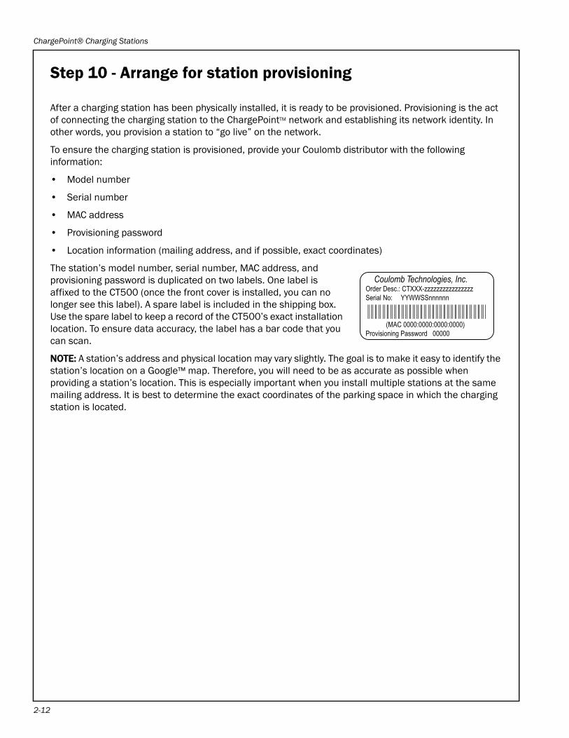
The station’s model number, serial number, MAC address, and provisioning password is duplicated on two labels. One label is affixed to the CT500 (once the front cover is installed, you can no longer see this label). A spare label is included in the shipping box. Use the spare label to keep a record of the CT500’s exact installation location. To ensure data accuracy, the label has a bar code that you can scan.
NOTE: A station’s address and physical location may vary slightly. The goal is to make it easy to identify the station’s location on a Google™ map. Therefore, you will need to be as accurate as possible when providing a station’s location. This is especially important when you install multiple stations at the same mailing address. It is best to determine the exact coordinates of the parking space in which the charging station is located.
Coulomb Technologies, Inc.Order Desc.: CTXXX-zzzzzzzzzzzzzzzzSerial No: YYWWSSnnnnnn
(MAC 0000:0000:0000:0000)Provisioning Password 00000
2
Troubleshooting 3
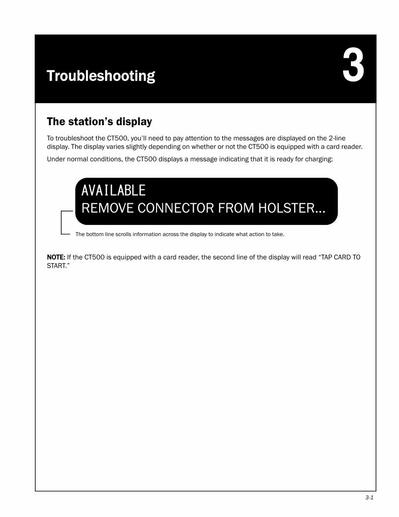
The station’s displayTo troubleshoot the CT500, you’ll need to pay attention to the messages are displayed on the 2-line display. The display varies slightly depending on whether or not the CT500 is equipped with a card reader.Under normal conditions, the CT500 displays a message indicating that it is ready for charging:
NOTE: If the CT500 is equipped with a card reader, the second line of the display will read “TAP CARD TO START.”
The bottom line scrolls information across the display to indicate what action to take.
AVAILABLEREMOVE CONNECTOR FROM HOLSTER...
3-1
ChargePoint® Charging Stations
3-2
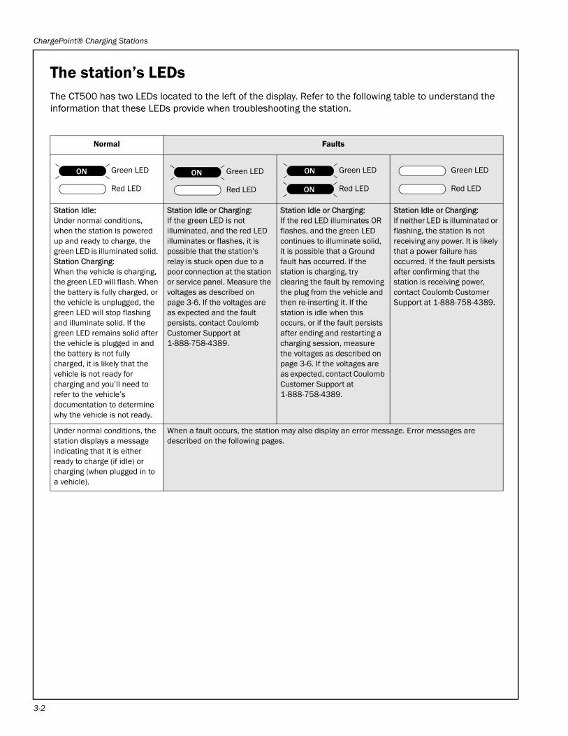
The station’s LEDsThe CT500 has two LEDs located to the left of the display. Refer to the following table to understand the information that these LEDs provide when troubleshooting the station.
Normal Faults
Station Idle:Under normal conditions, when the station is powered up and ready to charge, the green LED is illuminated solid. Station Charging:When the vehicle is charging, the green LED will flash. When the battery is fully charged, or the vehicle is unplugged, the green LED will stop flashing and illuminate solid. If the green LED remains solid after the vehicle is plugged in and the battery is not fully charged, it is likely that the vehicle is not ready for charging and you’ll need to refer to the vehicle’s documentation to determine why the vehicle is not ready.
Station Idle or Charging:If the green LED is not illuminated, and the red LED illuminates or flashes, it is possible that the station’s relay is stuck open due to a poor connection at the station or service panel. Measure the voltages as described on page 3-6. If the voltages are as expected and the fault persists, contact Coulomb Customer Support at 1-888-758-4389.
Station Idle or Charging:If the red LED illuminates OR flashes, and the green LED continues to illuminate solid, it is possible that a Ground fault has occurred. If the station is charging, try clearing the fault by removing the plug from the vehicle and then re-inserting it. If the station is idle when this occurs, or if the fault persists after ending and restarting a charging session, measure the voltages as described on page 3-6. If the voltages are as expected, contact Coulomb Customer Support at 1-888-758-4389.
Station Idle or Charging:If neither LED is illuminated or flashing, the station is not receiving any power. It is likely that a power failure has occurred. If the fault persists after confirming that the station is receiving power, contact Coulomb Customer Support at 1-888-758-4389.
Under normal conditions, the station displays a message indicating that it is either ready to charge (if idle) or charging (when plugged in to a vehicle).
When a fault occurs, the station may also display an error message. Error messages are described on the following pages.
Green LED
Red LED
ON Green LED
Red LED
ON Green LED
Red LED
ON
ON
Green LED
Red LED
Troubleshooting
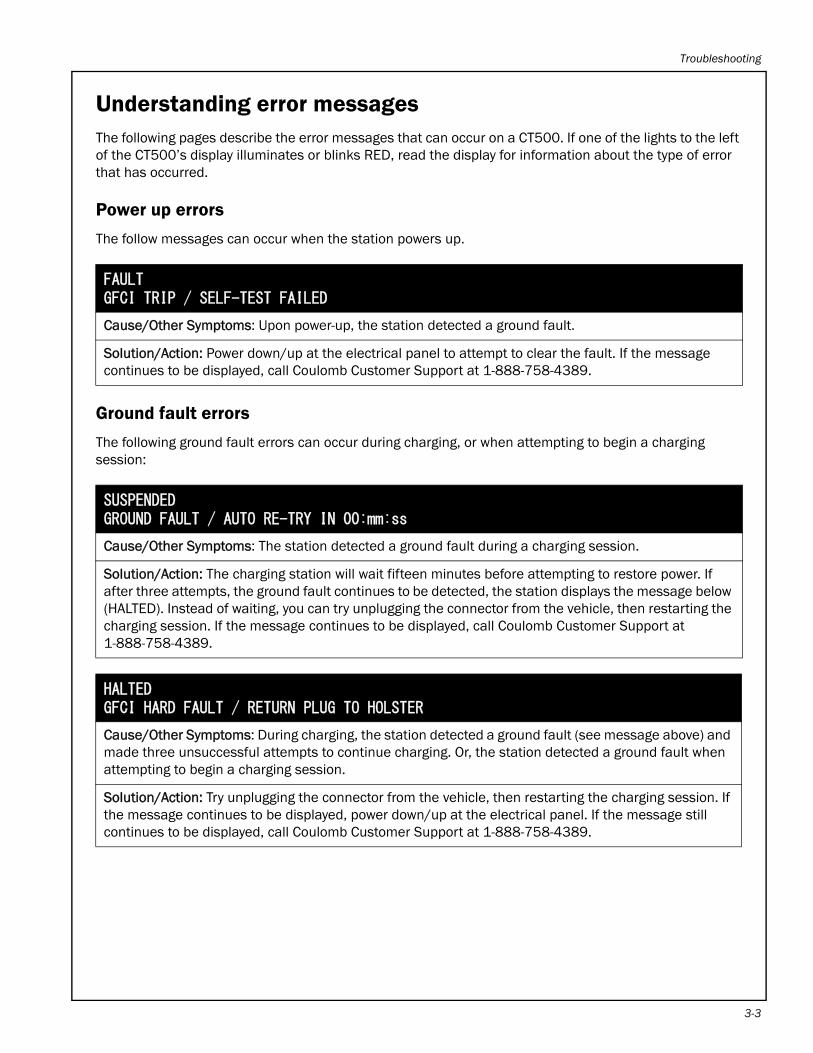
Understanding error messagesThe following pages describe the error messages that can occur on a CT500. If one of the lights to the left of the CT500’s display illuminates or blinks RED, read the display for information about the type of error that has occurred.
Power up errors
The follow messages can occur when the station powers up.
Ground fault errors
The following ground fault errors can occur during charging, or when attempting to begin a charging session:
FAULTGFCI TRIP / SELF-TEST FAILED
Cause/Other Symptoms: Upon power-up, the station detected a ground fault.
Solution/Action: Power down/up at the electrical panel to attempt to clear the fault. If the message continues to be displayed, call Coulomb Customer Support at 1-888-758-4389.
SUSPENDEDGROUND FAULT / AUTO RE-TRY IN 00:mm:ss
Cause/Other Symptoms: The station detected a ground fault during a charging session.
Solution/Action: The charging station will wait fifteen minutes before attempting to restore power. If after three attempts, the ground fault continues to be detected, the station displays the message below (HALTED). Instead of waiting, you can try unplugging the connector from the vehicle, then restarting the charging session. If the message continues to be displayed, call Coulomb Customer Support at 1-888-758-4389.
HALTEDGFCI HARD FAULT / RETURN PLUG TO HOLSTER
Cause/Other Symptoms: During charging, the station detected a ground fault (see message above) and made three unsuccessful attempts to continue charging. Or, the station detected a ground fault when attempting to begin a charging session.
Solution/Action: Try unplugging the connector from the vehicle, then restarting the charging session. If the message continues to be displayed, power down/up at the electrical panel. If the message still continues to be displayed, call Coulomb Customer Support at 1-888-758-4389.
3-3
ChargePoint® Charging Stations
3-4
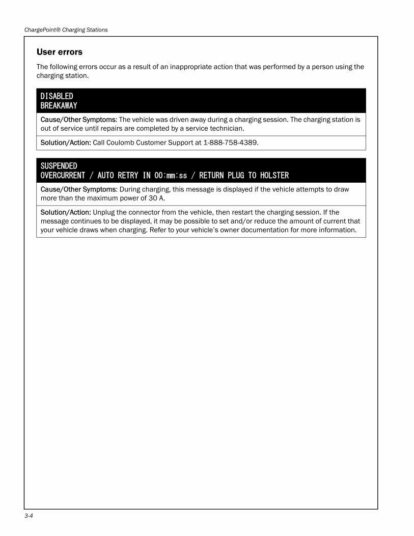
User errors
The following errors occur as a result of an inappropriate action that was performed by a person using the charging station.
DISABLEDBREAKAWAY
Cause/Other Symptoms: The vehicle was driven away during a charging session. The charging station is out of service until repairs are completed by a service technician.
Solution/Action: Call Coulomb Customer Support at 1-888-758-4389.
SUSPENDEDOVERCURRENT / AUTO RETRY IN 00:mm:ss / RETURN PLUG TO HOLSTER
Cause/Other Symptoms: During charging, this message is displayed if the vehicle attempts to draw more than the maximum power of 30 A.
Solution/Action: Unplug the connector from the vehicle, then restart the charging session. If the message continues to be displayed, it may be possible to set and/or reduce the amount of current that your vehicle draws when charging. Refer to your vehicle’s owner documentation for more information.
Troubleshooting
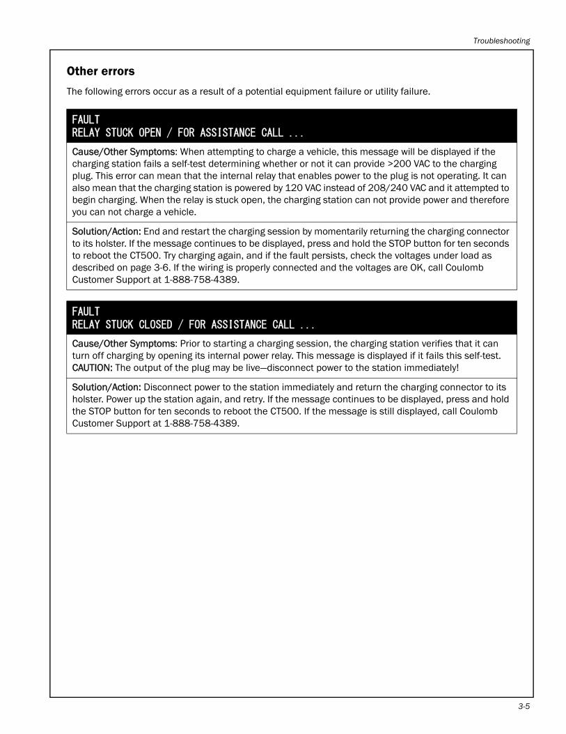
Other errors
The following errors occur as a result of a potential equipment failure or utility failure.
FAULTRELAY STUCK OPEN / FOR ASSISTANCE CALL ...
Cause/Other Symptoms: When attempting to charge a vehicle, this message will be displayed if the charging station fails a self-test determining whether or not it can provide >200 VAC to the charging plug. This error can mean that the internal relay that enables power to the plug is not operating. It can also mean that the charging station is powered by 120 VAC instead of 208/240 VAC and it attempted to begin charging. When the relay is stuck open, the charging station can not provide power and therefore you can not charge a vehicle.
Solution/Action: End and restart the charging session by momentarily returning the charging connector to its holster. If the message continues to be displayed, press and hold the STOP button for ten seconds to reboot the CT500. Try charging again, and if the fault persists, check the voltages under load as described on page 3-6. If the wiring is properly connected and the voltages are OK, call Coulomb Customer Support at 1-888-758-4389.
FAULTRELAY STUCK CLOSED / FOR ASSISTANCE CALL ...
Cause/Other Symptoms: Prior to starting a charging session, the charging station verifies that it can turn off charging by opening its internal power relay. This message is displayed if it fails this self-test. CAUTION: The output of the plug may be live—disconnect power to the station immediately!
Solution/Action: Disconnect power to the station immediately and return the charging connector to its holster. Power up the station again, and retry. If the message continues to be displayed, press and hold the STOP button for ten seconds to reboot the CT500. If the message is still displayed, call Coulomb Customer Support at 1-888-758-4389.
3-5
ChargePoint® Charging Stations
3-6
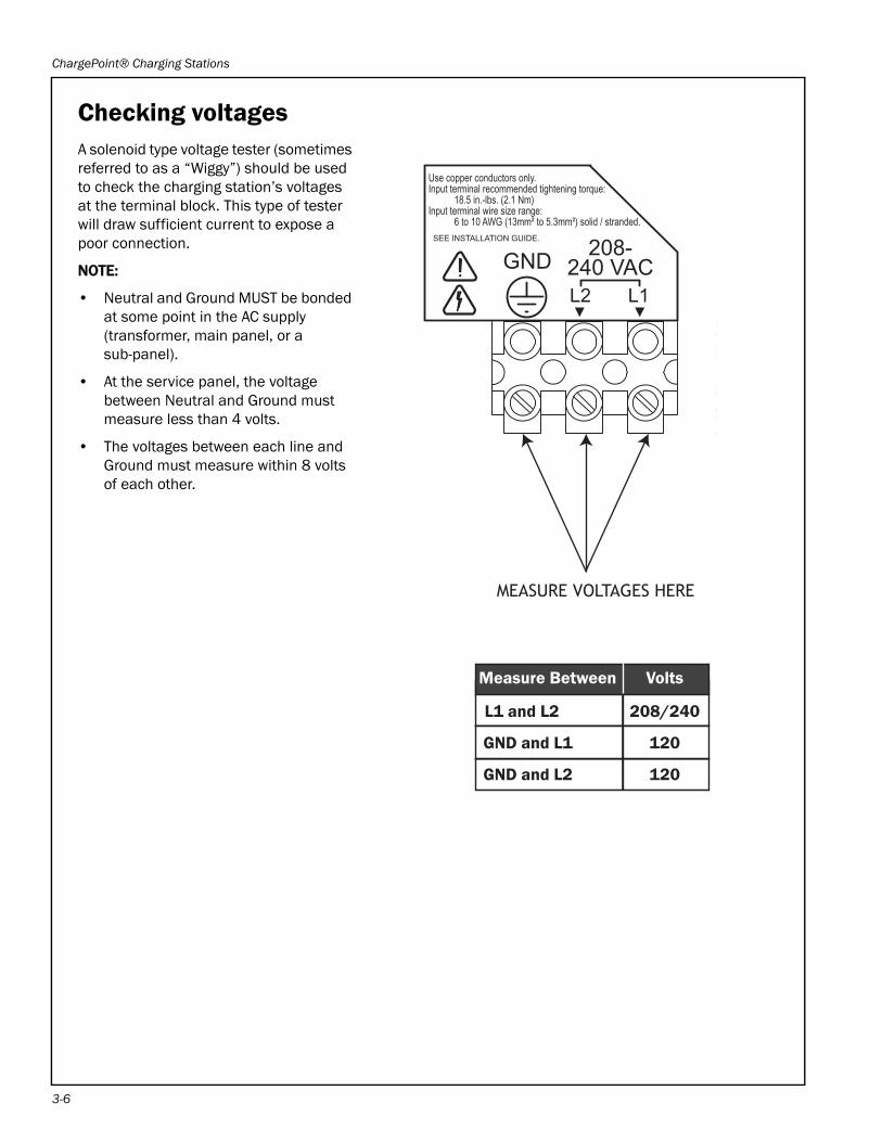
Checking voltagesA solenoid type voltage tester (sometimes referred to as a “Wiggy”) should be used to check the charging station’s voltages at the terminal block. This type of tester will draw sufficient current to expose a poor connection.
NOTE:
• Neutral and Ground MUST be bonded at some point in the AC supply (transformer, main panel, or a sub-panel).
• At the service panel, the voltage between Neutral and Ground must measure less than 4 volts.
• The voltages between each line and Ground must measure within 8 volts of each other.
MEASURE VOLTAGES HERE
GNDL1L2
208-240 VAC
SEE INSTALLATION GUIDE.
Use copper conductors only.Input terminal recommended tightening torque: 18.5 in.-lbs. (2.1 Nm)Input terminal wire size range: 6 to 10 AWG (13mm² to 5.3mm²) solid / stranded.
� �
Measure Between Volts
L1 and L2 208/240
GND and L1 120
GND and L2 120
Appendix A: Limited Product Warranty
COULOMB TECHNOLOGIES INC.LIMITED PRODUCT WARRANTY
This Limited Product Warranty applies to you, a customer who has purchased COULOMB’s ChargePoint™ Networked Charging Stations and/or related products (“Products”) from COULOMB TECHNOLOGIES, INC. (“COULOMB”) or one of its authorized distributors and not for resale.
LIMITED ONE-YEAR WARRANTY
Subject to the exclusions from warranty coverage set forth below, COULOMB warrants that the Product will be free from any defects in materials and/or workmanship (the “Limited Warranty”) for a period of one (1) year after the date of the initial installation of the Product (the “One-Year Warranty Period”). If the Product becomes defective in breach of the Limited Warranty, COULOMB will, upon written notice of the defect received during the One-Year Warranty period, either repair or replace, at Coulomb’s election, the Product if it proves to be defective; provided, that COULOMB will not be responsible for the cost of any labor associated with the repair or replacement of any defective Product.
FIVE-YEAR EXTENDED WARRANTY (Additional Charge Applies)
Subject to the exclusions from warranty coverage set forth below, if you have purchased a five (5) year extended warranty (“Five-Year Extended Warranty”), and if the Product becomes defective in breach of the Limited Warranty above at any time during the five (5) year period after the date of the initial installation of the Product (the “Five-Year Warranty Period”), COULOMB will, upon written notice of the defect received during the Five-Year Warranty Period, either repair, provide replacement parts for the defective parts of the Product or replace the Product, at Coulomb’s election, if it proves to be defective; provided, that COULOMB will not be responsible for the cost of any labor associated with the repair or replacement of any defective Product.
COULOMB’s OPTIONS
You acknowledge that replacement products provided by Coulomb under each of the Limited Warranty and the Five-Year Extended Warranty may be remanufactured or reconditioned Products or, if the exact Product is no longer manufactured by COULOMB, a Product with substantially similar functionality (“Replacement Products”). Any Replacement Products so furnished will be warranted for the remainder of the original Warranty Period or ninety (90) days from the date of delivery of such Replacement Product, whichever is greater. Should COULOMB be unable to repair or replace the Product, COULOMB will refund the purchase price of the Product.
EXCLUSIONS FROM LIMITED WARRANTY AND FIVE-YEAR EXTENDED WARRANTY
IMPORTANT: The Limited Warranty and, if purchased, the Five Year Extended Warranty on your Product shall not apply to defects, or service repairs, resulting from any of the following:
• Alteration or modification of the Product in any way not approved in writing by COULOMB.
• Vandalism, abuse, damage or otherwise being subjected to problems caused by negligence (including but not limited to physical damage from being struck by a vehicle) or misapplication, or use of the Products other than as specified in the applicable COULOMB documentation.
• Installation or relocation of the Products unless performed by COULOMB or by a Coulomb authorized installer or service provider.
• Improper site preparation or maintenance.
• Damage as a result of accidents, extreme power surge, extreme electromagnetic field, acts of nature or other causes beyond the control of COULOMB.
• Use of the Product with software, interfacing, parts or supplies not supplied by COULOMB.
You are responsible for the proper installation and maintenance of the Product. Any service or repairs beyond the scope of the Limited Warranty or the Five-Year Extended Warranty above are subject to COULOMB’s then prevailing current labor rates and other applicable charges.
A-1
ChargePoint® Charging Stations
A-2
Third Party Products
The above Limited Warranty and Five-Year Extended Warranty are exclusive of products manufactured by third parties (“Third Party Products”). If such third party manufacturer provides a separate warranty with respect to the Third Party Product, COULOMB will include such warranty in the packaging of the COULOMB Product.
OBTAINING WARRANTY SERVICE
To obtain warranty service you must: (a) obtain a return materials authorization number (“RMA#”) from COULOMB by contacting 1-877-370-3802 (or for customers outside the U.S., contact 408-370-3802) and ask for Customer Service, and (b) deliver the Product, in accordance with the instructions provided by COULOMB, along with proof of purchase in the form of a copy of the bill of sale including the Product’s serial number, contact information, RMA# and detailed description of the defect, in either its original package or packaging providing the Product with a degree of protection equivalent to that of the original packaging, to COULOMB at the address below. You agree to obtain adequate insurance to cover loss or damage to the Product during shipment.
If you obtain an RMA# and return the defective Product as described above, COULOMB will pay the cost of returning the Product to COULOMB. Otherwise, you agree to bear such cost, and prior to receipt by COULOMB, you assume risk of any loss or damage to the Product. COULOMB is responsible for the cost of return shipment to you if the COULOMB Product is found to be defective.
Returned products which are found by COULOMB to be not defective, returned out-of-warranty or otherwise ineligible for warranty service will be repaired or replaced at COULOMB’s standard charges and shipped back to you at your expense.
At COULOMB’s sole option, COULOMB may perform repair service on the Product at your facility, and you agree to provide COULOMB with all reasonable access to such facility and the Product, as required. On-site repair service is not available outside the United States.
All replaced parts, whether under warranty or not, are the property of COULOMB.
WARRANTY LIMITATIONS
The LIMITED warrantY set forth above IS exclusive and no other warranty, whether written or oral, is expressed or implied BY COULOMB, TO THE MAXIMUM EXTENT PERMITTED BY LAW. THERE ARE NO OTHER WARRANTIES RESPECTING THE PRODUCT AND DOCUMENTATION AND SERVICES PROVIDED UNDER THIS AGREEMENT, INCLUDING WITHOUT LIMITATION ANY WARRANTY OF DESIGN, MERCHANTABILITY, FITNESS FOR A PARTICULAR PURPOSE (EVEN IF COULOMB OR DISTRIBUTOR HAS BEEN INFORMED OF SUCH PURPOSE) OR AGAINST INFRINGEMENT.
Some states or jurisdictions do not allow the exclusion of express or implied warranties so the above exclusions may not apply to you. IF ANY IMPLIED WARRANTY CANNOT BE DISCLAIMED UNDER APPLICABLE LAW, THEN SUCH IMPLIED WARRANTY SHALL BE LIMITED IN DURATION TO THE LIMITED WARRANTY PERIOD DESCRIBED ABOVE. NO WARRANTIES APPLY AFTER THE TOTAL WARRANTY PERIOD. Some states or jurisdictions do not allow limitations on how long an implied warranty lasts, so the above limitation may not apply to you.
NO AGENT OF COULOMB IS AUTHORIZED TO ALTER OR EXCEED THE WARRANTY OBLIGATIONS OF COULOMB.
COULOMB SPECIFICALLY DOES NOT WARRANT THAT ANY SOFTWARE WILL BE ERROR FREE OR OPERATE WITHOUT INTERRUPTION.
THE REMEDIES IN THIS LIMITED PRODUCT WARRANTY ARE YOUR SOLE AND EXCLUSIVE REMEDIES.
LIMITATIONS OF LIABILITY
You acknowledge and agree that the consideration which you paid to COULOMB or one of its authorized distributors does not include any consideration by COULOMB or one of its authorized distributors of the risk of consequential, indirect or incidental damages which may arise in connection with your use of, or inability to use, the Product. THUS, COULOMB OR ONE OF ITS AUTHORIZED DISTRIBUTORS WILL NOT BE LIABLE FOR ANY INDIRECT, INCIDENTAL, SPECIAL, PUNITIVE OR CONSEQUENTIAL DAMAGES, INCLUDING WITHOUT LIMITATION LOST PROFITS, LOST BUSINESS, LOST DATA, LOSS OF USE, OR COST OF COVER INCURRED BY YOU ARISING OUT OF OR RELATED TO YOUR PURCHASE OR USE OF, OR INABILITY TO USE, THIS PRODUCT OR THE SERVICES, UNDER ANY THEORY OF LIABILITY, WHETHER IN AN ACTION IN CONTRACT, STRICT LIABILITY, TORT (INCLUDING NEGLIGENCE) OR OTHER LEGAL OR EQUITABLE THEORY, EVEN IF COULOMB KNEW OR SHOULD HAVE KNOWN OF THE POSSIBILITY OF SUCH DAMAGES. IN ANY EVENT, THE CUMULATIVE LIABILITY OF COULOMB OR ONE OF ITS AUTHORIZED DISTRIBUTORS FOR ALL CLAIMS WHATSOEVER RELATED TO THIS PRODUCT OR THE SERVICE WILL NOT EXCEED THE PRICE YOU PAID FOR THIS PRODUCT.
THE LIMITATIONS SET FORTH HEREIN ARE INTENDED TO LIMIT THE LIABILITY OF COULOMB AND SHALL APPLY NOTWITHSTANDING ANY FAILURE OF ESSENTIAL PURPOSE OF ANY LIMITED REMEDY.
Limited Product Warranty
Some states or jurisdictions do not allow the exclusion or limitation of incidental or consequential damages, so the above limitation or exclusion may not apply to you.
THIS LIMITED PRODUCT WARRANTY GIVES YOU SPECIFIC LEGAL RIGHTS AND YOU MAY ALSO HAVE OTHER RIGHTS WHICH VARY FROM STATE TO STATE OR JURISDICTION TO JURISDICTION.
ADDITIONAL INFORMATION
This Limited Product Warranty is valid for U.S.A. and Can only.
This Limited Product Warranty shall be governed by and construed in accordance with the laws of the State of California, U.S.A., exclusive of its conflict of laws principles. The U.N. Convention on Contracts for the International Sale of Goods shall not apply.
This Limited Product Warranty is the entire and exclusive agreement between you and COULOMB with respect to its subject matter, and any modification or waiver of any provision of this statement is not effective unless expressly set forth in writing by an authorized representative of COULOMB.
The Limited Product Warranty is not transferable by you to anyone else.
All inquiries or claims made under this Limited Product Warranty must be sent to COULOMB’s address as follows:
Coulomb Technologies, Inc.1692 Dell Avenue.Campbell, California 95008-6901Tel: 408-370-3802Fax: 408-370-3847
A-3


Coulomb Technologies Inc.
1692 Dell Ave.
Campbell, CA 95008-6901 USA
US toll free: +1-877-370-3802
www.coulombtech.com
www.mychargepoint.net