Embed Size (px)
Citation preview

C.T.M. MOBILITY SCOOTERC.T.M. MOBILITY SCOOTERC.T.M. MOBILITY SCOOTER1-Series Instruction Booklet
HS-115
HS-118

1-Series Instruction Booklet
TABLE OF CONTENTS
INTRODUCTION
IMPORTANT PRECAUTIONS
SAFETY INFORMATION ON ELECTROMAGNETICINTERFERENCE (EMI)
IDENTIFICATION OF PARTS
CHARGING THE BATTERIES
DISASSEMBLING YOUR SCOOTER
TROUBLESHOOTING
CAUTION
SPECIFICATION
----------------------------------------------------------1
------------------------------------------2
--------------------------------------------------3
-------------------------------------------5
------------------------------------------9
--------------------------------10
--------------------------------------------------12
-----------------------------------------------------------------13
--------------------------------------------------------14
1-Series Instruction Booklet
If you have any questions, you can contact:
or your local dealer:
INTRODUCTION
1
Thank you and congratulations on purchasing your new C.T.M. Mobility Scooter.
Indications for Use:The C.T.M. Mobility Scooters HS-115 and HS-118 are indoor/outdoor scooters that providetransportation for a disabled or elderly person.
We pride ourselves on providing safe and comfortable products. Our goal is to ensureyour complete satisfaction with our product. We are certain that you will enjoy yourC.T.M. mobility scooter.
Please read and observe all warning and instruction provided in the owner's manualbefore operating this scooter. Also, retain this booklet for future reference.
C.T.M.HOMECARE PRODUCT, INC.13815 Magnolia Ave. #B, Chino CA 91710
Toll Free : 1-866-466-8168 Tel : 909-590-1388 Fax : 909-590-3365E-Mail : [email protected] http : //www.ctmhomecare.com

1-Series Instruction Booklet
IMPORTANT PRECAUTIONS
2
‧Only one person at a time could ride a C.T.M. Mobility Scooter.
‧Maximum load is 115 kg / 255 lbs.
‧Turn key off before getting on or off.
‧Always drive carefully and be aware of others using the same area.
‧Always use pedestrian crossings wherever possible. Take extreme care when crossing roads.
‧Do not drive on slope exceeding 6 degree, and take extreme care when turning on slope.
‧Do not use full power when turning to sharp corner.
‧Take great care and drive in low speed when backing up, riding downhill or on uneven surface, and climbing curb.
‧Please use the lowest speed when driving through the descending road or uneven terrain. If speed is too fast, leave your hand off the handle bar, let the scooter stop. Make sure safety and start again.
‧A slow speed must always be used when ascending, descending or traversing aslope or incline and also on uneven terrain, ramps and soft or loose surfaces, such as gravel or grass.
‧To prevent any danger, do not turn around at high speed on ascending, descending ramp.
‧Scooter may not operate well in high humidity.
‧Do not leave the powered scooter in a rain storm of any kind.
‧Do not use the powered scooter in a shower.
‧Direct exposure to rain or dampness will cause the scooter to malfunction electrically and mechanically; may cause the powered scooter to prematurely rust.
‧Never put scooter in neutral when staying on slopes.
‧Follow traffic laws when riding outside.
‧When scooter on moving transport vehicles, do not sit or stay on scooter.

1-Series Instruction Booklet
3
SAFETY INFORMATION ONELECTROMAGNETIC INTERFERENCE (EMI)
CAUTION : It is very important that you read this information regarding the possible effects of Electromagnetic Interference on your motorized scooter.
Powered wheelchairs and motorized scooters may be susceptible to electromagneticinterference (EMI), which is interfering electromagnetic energy (EM) emitted from sourcessuch a radio stations, TV stations, amateur radio (HAM) transmitters, two-way radios,and cellular phones. The interference (from radio wave sources) can cause the motorizedscooter to release its brakes, move by itself, or move in unintended directions. It can alsopermanently damage the motorized scooter control system. The intensity of the interferingEM energy can be measured in volts per meter (V/m). Each motorized scooter can resistEMI up to certain intensity. This is called its "immunity level." The higher the immunitylevel, the greater the protection. At this time, current technology is capable of achievingat least a 20 V/m immunity level, which would provide useful protection from the morecommon sources of radiated EMI. This immunity level of this motorized scooter modelis 30 V/m.
There are a number of sources of relatively intense electromagnetic fields in the everydayenvironment. Some of these sources are obvious and easy to avoid. Others are not apparentand exposure is unavoidable. However, we believe that by following the warnings listedbelow, your risk to EMI will be minimized.
1.Hand-held portable transceivers (transmitters-receivers) with the antenna mounted directly on the transmitting unit. Examples include: citizens band (CB) radios, "walkie talkie," security, fire, and police transceivers, cellular telephones, and other personal communication devices;
2.Medium-range mobile transceivers, such as those used in police cars, fire trucks, ambulances, and taxis. These usually have the antenna mounted on the outside of the vehicle; and
3.Long-range transmitters and transceivers such as commercial broadcast transmitters (radio and TV broadcast antenna towers) and amateur (HAM) radios.
The sources of radiated EMI can be broadly classified into three types :
Some cellular telephones and similar devices transmit signals while theyare ON, even when not being used.
Other types of hand-held devices, such as cordless phones, laptopcomputers, AM/FM radios, TV sets, CD players, and cassette players,and small appliances, such as electric shavers and hair dryers, so faras we know, are not likely to cause EMI problems to your motorizedscooter.
1-Series Instruction Booklet
There is no easy way to evaluate their effect on the overall immunityof the motorized scooter.
4
Motorized Scooter Electromagnetic Interference :
Because EM energy rapidly becomes more intense as one move closer to the transmittingantenna (source), the EM fields from hand-held radio wave sources (transceivers) are ofspecial concern. It is possible to unintentionally bring high levels of EM energy very closeto the motorized scooter control system while using these devices. This can affect motorizedscooter movement and braking. Therefore, the warnings listed below are recommended toprevent possible interference with the control system of the motorized scooter.
Warnings :
Electromagnetic interference (EMI) from sources such as radio and TV stations, amateurradio (HAM) transmitters, two-way radios, and cellular phones can affect motorized scooters.Following the warnings listed below should reduce the chance of unintended brake releaseor motorized scooter movement which could result in serious injury.
1.Do not operate hand-held transceivers (transmitters-receivers), such as citizens band (CB) radios, or turn ON personal communication devices, such as cellular phones, while the motorized scooter is turned ON;
2.Be aware of nearby transmitters, such as radio or TV stations, and try to avoid coming close to them;
3.If unintended movement or brake release occurs, turn the motorized scooter OFF as soon as it is safe;
4.Be aware that adding accessories or components, or modifying the motorized scooter, may make it more susceptible to EMI; and
Important Information :
1.20 volts per meter (V/m) is a generally achievable and useful immunity level against EMI (as of May 1994). The higher the level, the greater the protection.
2.The immunity level of this product is 30 V/m.
5.Report all incidents of unintended movement or brake release to the distributor listed on the inside front cover of this manual. Note whether there is a source of EMI nearby.
1-Series Instruction Booklet
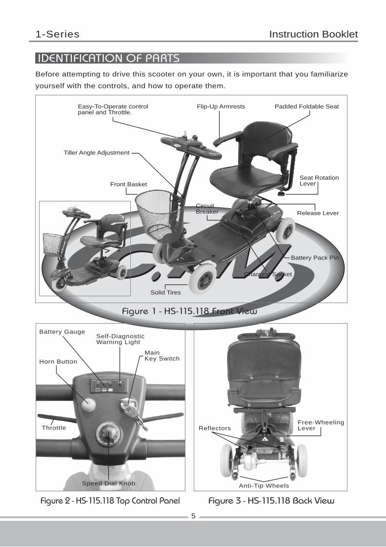
Figure 2 - HS-115.118 Top Control Panel Figure 3 - HS-115.118 Back View
Figure 1 - HS-115.118 Front View
Horn Button
Throttle
MainKey Switch
Battery GaugeSelf-DiagnosticWarning Light
Speed Dial Knob
IDENTIFICATION OF PARTS
5
Before attempting to drive this scooter on your own, it is important that you familiarize
yourself with the controls, and how to operate them.
Reflectors
Anti-Tip Wheels
Free-WheelingLever
Easy-To-Operate controlpanel and Throttle.
Flip-Up Armrests
Front Basket
Padded Foldable Seat
Solid Tires
Tiller Angle Adjustment
CircuitBreaker
Seat RotationLever
Release Lever
Battery Pack Pin
Charging Socket
1-Series Instruction Booklet
6
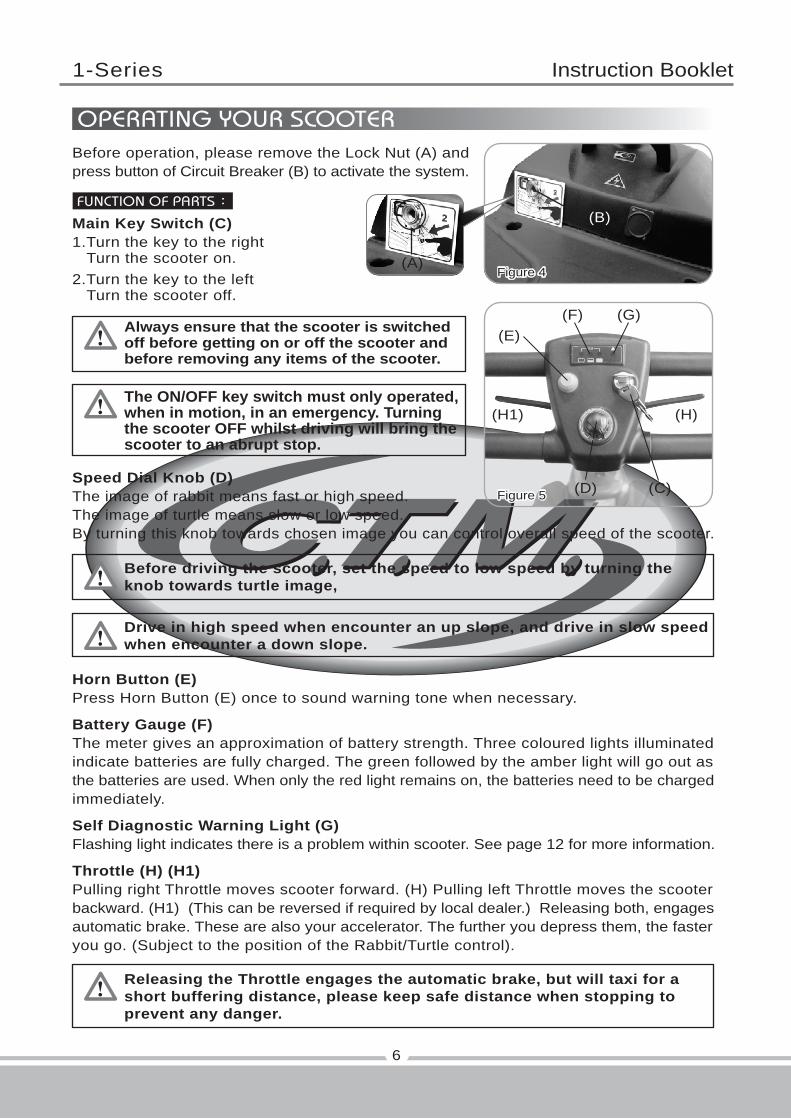
FUNCTION OF PARTS:
Main Key Switch (C)1.Turn the key to the right Turn the scooter on.2.Turn the key to the left Turn the scooter off.
Always ensure that the scooter is switchedoff before getting on or off the scooter andbefore removing any items of the scooter.
The ON/OFF key switch must only operated,when in motion, in an emergency. Turningthe scooter OFF whilst driving will bring thescooter to an abrupt stop.
Before driving the scooter, set the speed to low speed by turning theknob towards turtle image,
Drive in high speed when encounter an up slope, and drive in slow speedwhen encounter a down slope.
Releasing the Throttle engages the automatic brake, but will taxi for ashort buffering distance, please keep safe distance when stopping toprevent any danger.
Speed Dial Knob (D)The image of rabbit means fast or high speed.The image of turtle means slow or low speed.By turning this knob towards chosen image you can control overall speed of the scooter.
Horn Button (E)Press Horn Button (E) once to sound warning tone when necessary.
Battery Gauge (F)The meter gives an approximation of battery strength. Three coloured lights illuminatedindicate batteries are fully charged. The green followed by the amber light will go out asthe batteries are used. When only the red light remains on, the batteries need to be chargedimmediately.
Self Diagnostic Warning Light (G)Flashing light indicates there is a problem within scooter. See page 12 for more information.
Throttle (H) (H1)Pulling right Throttle moves scooter forward. (H) Pulling left Throttle moves the scooterbackward. (H1) (This can be reversed if required by local dealer.) Releasing both, engagesautomatic brake. These are also your accelerator. The further you depress them, the fasteryou go. (Subject to the position of the Rabbit/Turtle control).
Figure 5 (C)
(H)(H1)
(E)
(D)
(F) (G)
Figure 4
Before operation, please remove the Lock Nut (A) andpress button of Circuit Breaker (B) to activate the system.
(B)
(A)
OPERATING YOUR SCOOTER

1-Series Instruction Booklet
1.Lift up the lever (I) to disengage the pin.2.Simultaneously, adjust the steering fore-aft to the most comfortable angle. Release lever (I) and ensure the pin is fully engaged to lock the steering column in position.
1.Lift lever (J) upward to disengage pin.2.Simultaneously, rotate seat (K) (or lift up to disassemble the seat) to the most comfortable angle. Release lever (J) and ensure the pin is fully engaged to lock the seat in position.
If scooter's circuit system malfunctions or over loaded, the circuit system will automaticshut down the power to ensure driver's safety. After the power is off, press button (L) toregain power.
To push scooter for short distances, put it in freewheel mode by pushing forward on free-wheel lever to N. This disables the drive system and brake system. To take the scooterout of freewheel mode, pull the free-wheel lever backward to D to re-engage the drive andbrake system.
7
Tiller Angle Adjustment :
Seat Rotation Adjustment :
Figure 7
(J)
(K)
Figure 6 (I)
Circuit Breaker :
Free-Wheeling Lever :
Figure 9
(L1)
Figure 8
(L)
1-Series Instruction Booklet
8
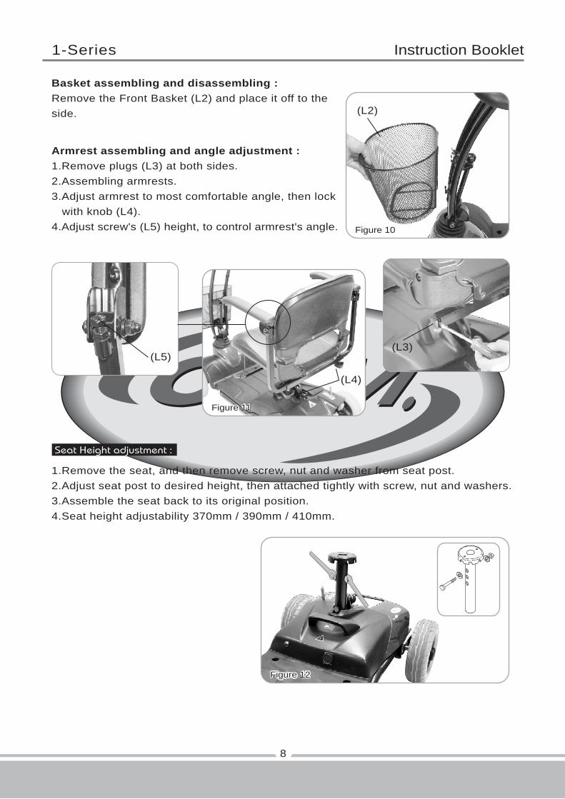
Basket assembling and disassembling :Remove the Front Basket (L2) and place it off to the side.
Armrest assembling and angle adjustment :1.Remove plugs (L3) at both sides.2.Assembling armrests.3.Adjust armrest to most comfortable angle, then lock with knob (L4).4.Adjust screw's (L5) height, to control armrest's angle.
Seat Height adjustment :
1.Remove the seat, and then remove screw, nut and washer from seat post.2.Adjust seat post to desired height, then attached tightly with screw, nut and washers.3.Assemble the seat back to its original position.4.Seat height adjustability 370mm / 390mm / 410mm.
Figure 11
(L4)
(L3)(L5)
Figure 10
(L2)
Figure 12
1-Series Instruction Booklet
The time needed to recharge will vary depending on the depletion of thebatteries. Charging for longer than necessary will not harm the batteries.They can not be overcharged.
9
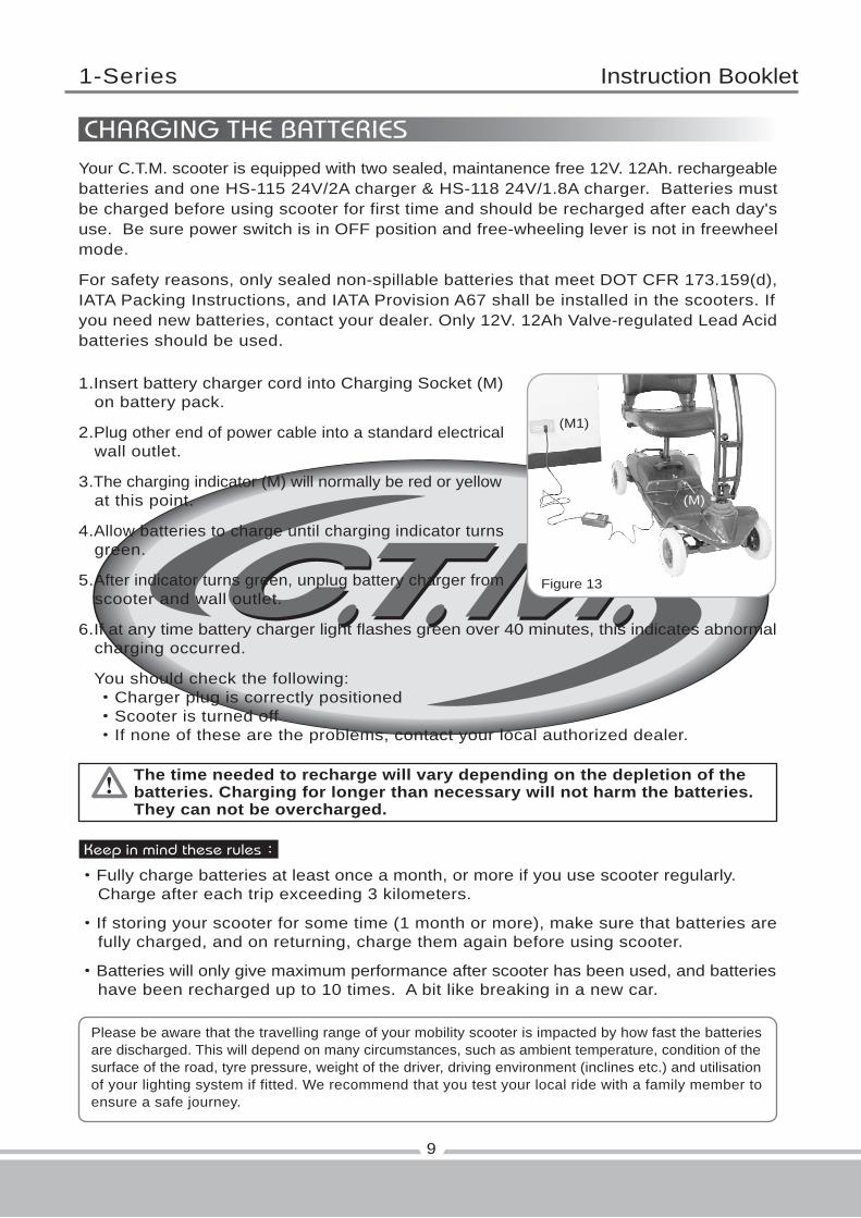
CHARGING THE BATTERIESYour C.T.M. scooter is equipped with two sealed, maintanence free 12V. 12Ah. rechargeablebatteries and one HS-115 24V/2A charger & HS-118 24V/1.8A charger. Batteries mustbe charged before using scooter for first time and should be recharged after each day'suse. Be sure power switch is in OFF position and free-wheeling lever is not in freewheelmode.
For safety reasons, only sealed non-spillable batteries that meet DOT CFR 173.159(d),IATA Packing Instructions, and IATA Provision A67 shall be installed in the scooters. Ifyou need new batteries, contact your dealer. Only 12V. 12Ah Valve-regulated Lead Acidbatteries should be used.
1.Insert battery charger cord into Charging Socket (M) on battery pack.
2.Plug other end of power cable into a standard electrical wall outlet.
3.The charging indicator (M) will normally be red or yellow at this point.
4.Allow batteries to charge until charging indicator turns green.
5.After indicator turns green, unplug battery charger from scooter and wall outlet.
6.If at any time battery charger light flashes green over 40 minutes, this indicates abnormal charging occurred.
You should check the following: ‧Charger plug is correctly positioned ‧Scooter is turned off ‧If none of these are the problems, contact your local authorized dealer.
Figure 13
(M)
(M1)
Keep in mind these rules:
‧Fully charge batteries at least once a month, or more if you use scooter regularly. Charge after each trip exceeding 3 kilometers.
‧If storing your scooter for some time (1 month or more), make sure that batteries are fully charged, and on returning, charge them again before using scooter.
‧Batteries will only give maximum performance after scooter has been used, and batteries have been recharged up to 10 times. A bit like breaking in a new car.
Please be aware that the travelling range of your mobility scooter is impacted by how fast the batteriesare discharged. This will depend on many circumstances, such as ambient temperature, condition of thesurface of the road, tyre pressure, weight of the driver, driving environment (inclines etc.) and utilisationof your lighting system if fitted. We recommend that you test your local ride with a family member toensure a safe journey.
1-Series Instruction Booklet
When assembling battery pack (O), make sure to aim for the battery terminalconnection for proper electricity conductivity.
10
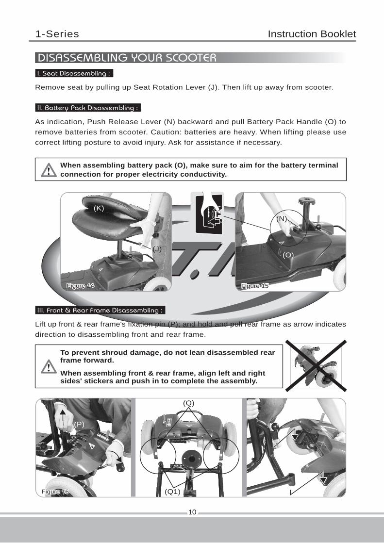
DISASSEMBLING YOUR SCOOTERI. Seat Disassembling :
Remove seat by pulling up Seat Rotation Lever (J). Then lift up away from scooter.
II. Battery Pack Disassembling :
As indication, Push Release Lever (N) backward and pull Battery Pack Handle (O) toremove batteries from scooter. Caution: batteries are heavy. When lifting please usecorrect lifting posture to avoid injury. Ask for assistance if necessary.
Figure 15Figure 14
(J)
(K)
To prevent shroud damage, do not lean disassembled rearframe forward.
When assembling front & rear frame, align left and rightsides' stickers and push in to complete the assembly.
III. Front & Rear Frame Disassembling :
Lift up front & rear frame's fixation pin (P); and hold and pull rear frame as arrow indicatesdirection to disassembling front and rear frame.
Figure 16
(P)
(Q)
(Q1)
(M)
(N)
(O)
1-Series Instruction Booklet
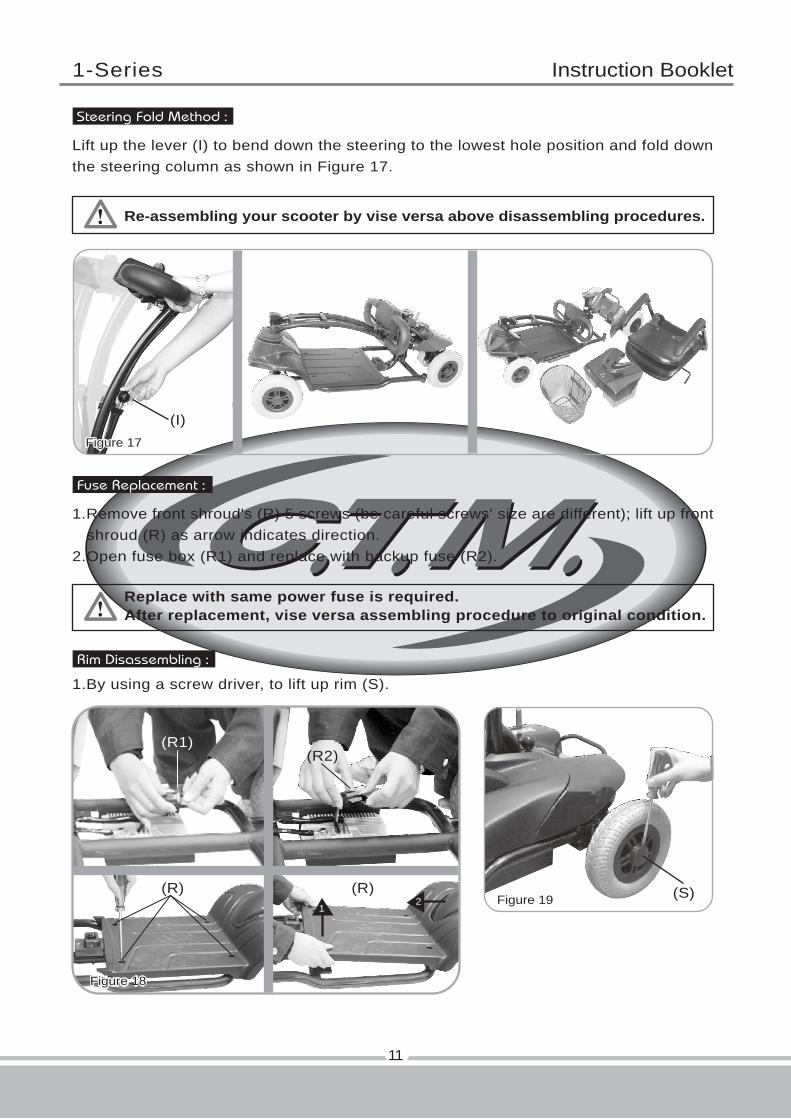
Re-assembling your scooter by vise versa above disassembling procedures.
Replace with same power fuse is required.After replacement, vise versa assembling procedure to original condition.
Lift up the lever (I) to bend down the steering to the lowest hole position and fold downthe steering column as shown in Figure 17.
Fuse Replacement :
1.Remove front shroud's (R) 5 screws (be careful screws' size are different); lift up front shroud (R) as arrow indicates direction.2.Open fuse box (R1) and replace with backup fuse (R2).
11
Steering Fold Method :
Rim Disassembling :
1.By using a screw driver, to lift up rim (S).
Figure 19
Figure 18
Figure 17
(I)
12
(S)
(R1)
(R) (R)
(R2)

1-Series Instruction Booklet
12
TROUBLESHOOTING
Flash Description Meaning
1 Battery Low The batteries are running low.‧Recharge the batteries
2 Low Battery Fault The batteries have run out of charge.‧Recharge the batteries.
3 High Battery Fault Battery voltage is too high. This may occur ifovercharged &/or traveling down a long slope.‧If traveling down a slope, reduce your speed to minimize the amount of regenerative charging.‧Check the battery and associated connections and wiring.
4 Current Limit Time-out The motor has been exceeding its maximumcurrent rating for too long. This may be dueto a faulty motor.‧Check the motor and associated connections and wiring.‧Turn the controller off, leave for a few minutes and turn back on again.
5 Park Brake Fault Either a park brake release switch is activeor the park brake is faulty.‧Check the park brake and associated connections and wiring.‧Ensure any associated switches are in their correct positions.
6 Throttle OONAPU The Throttle is out of neutral when turning thecontroller on.‧Ensure the throttle is in neutral when turning the controller on.‧The Throttle may require re-calibration.
7 Speed Pot Fault The throttle, speed limit pot or their associatedwiring may be faulty.‧Check the throttle and speed pot and associated connections and wiring.
8 Motor Voltage Fault The motor or its associated wiring is faulty.‧Check the motor and associated connections and wiring.
9 Other error The controller may have an internal fault.‧Check all connections & wiring.

1-Series Instruction Booklet
In unlikely event of a panel display error, you need to re-set the displaysystem by cycling the on/off main switch. The display circuitry is independentof the motor control system. A display console error does not affect scooterspeed control.
1.Obstacle Climbing : Your scooter can climb obstacles and curbs of up to 35mm / 1.4" in height. Never attempt to overcome an obstacle when on an uphill or downhill gradient! Always approach obstacles straight on! Ensure that the front wheels and rear wheels move over the obstacle in one stroke, do not stop halfway!
2.The maximum gap the scooter can drive over is 100mm / 4",
1.Charge the batteries after each trip. If the scooter is not used for some time, batteries may lose their charge. Batteries should be charged at least once a month.
2.Check the battery gauge before driving to prevent power depletion.
3.Batteries will have an aging phenomenon, where the storage capacity will gradually decrease. If batteries are damaged, please wrap them in a plastic bag and contact your local dealer for proper disposal.
4.Do not disassemble battery and open sealed parts by yourself to prevent electric shock and burns from acid leakage,
5.Adjust speed to a slow speed when starting off to prevent sudden acceleration.
6.Never attempt to drive downhill backwards.
7.Try not to drive scooter at night or in rain or bad weather.
8.If storing your scooter for a long time (1 month or more), make sure that battery are fully charged, then disconnect the two batteries plugs (W), and store the scooter in a dry location.
9. Front basket (accessory), weight capacity 3kgs(6.5lbs).
13
CAUTION
OTHER
‧When driving scooter on ramp, adjust body center of gravity to keep scooter more safety.
General driving posture On ramp, forward your body willlet scooter more safety.

1-Series Instruction Booklet
39.8"
20.5"
35.6"
8"
8"
82 lbs
24 lbs
4 mph
255 lbs
1.2"
6 degree
1.4"
43"
Electro-Mechanical
Swivel Padded Foldable
17"
250W, 4700 r.p.m.
(2) 12V. 12Ah
20 lbs
6.2 Miles
2A Off Board
On / Off Key Switch,Battery Level Indicator,Speed Control Knob
39.4"
20.5"
35"
8"
8"
88 lbs
33 lbs
4 mph
255 lbs
1.4"
6 degree
1.4"
52"
Electro-Mechanical
Swivel Padded Foldable
17"
250W, 4700 r.p.m.
(2) 12V. 12Ah
20 lbs
6.2 Miles
1.8A Off Board
On / Off Key Switch,Battery Level Indicator,Speed Control Knob
SPECIFICATION
14
Overall Length
Overall Width
Overall Height
Front Wheels
Rear Wheels
Weight W/ Batteries
Weight Of Heaviest Piece
Max. Speed
Weight Capacity
Ground Clearance
Grade Climbable
Curb Climbable
Turning Radius
Brake
Seat Type
Seat Width
Motor Size
Battery Size
Battery Weight
Travel Range
Battery Charger
Electronics
SPECIFICATIONS HS-115 HS-118
*Subject to change without notice. ( Rev. 7, 2017/05/31 )
1-Series Instruction Booklet
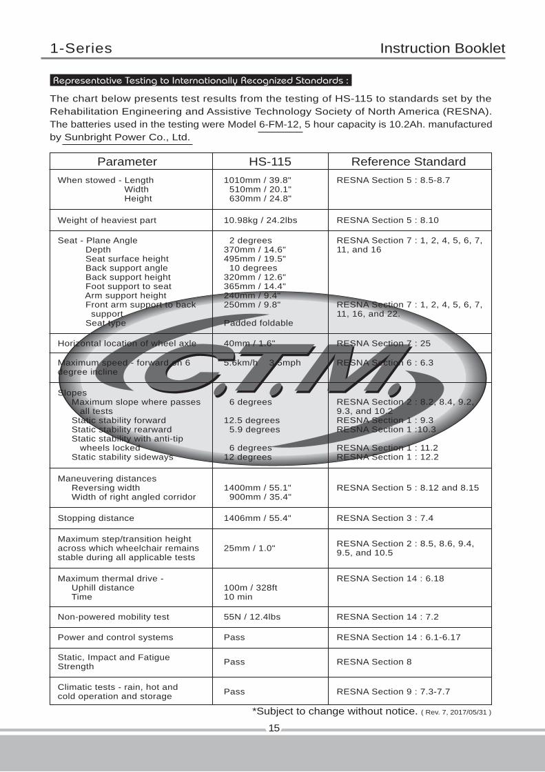
The chart below presents test results from the testing of HS-115 to standards set by theRehabilitation Engineering and Assistive Technology Society of North America (RESNA).The batteries used in the testing were Model 6-FM-12, 5 hour capacity is 10.2Ah. manufacturedby Sunbright Power Co., Ltd.
ParameterWhen stowed - Length Width Height
Weight of heaviest part
Horizontal location of wheel axle
Maximum speed - forward on 6degree incline
Stopping distance
Maneuvering distances Reversing width Width of right angled corridor
Slopes Maximum slope where passes all tests Static stability forward Static stability rearward Static stability with anti-tip wheels locked Static stability sideways
Seat - Plane Angle Depth Seat surface height Back support angle Back support height Foot support to seat Arm support height Front arm support to back support Seat type
1010mm / 39.8" 510mm / 20.1" 630mm / 24.8"
10.98kg / 24.2lbs
40mm / 1.6"
5.6km/h 3.5mph
1406mm / 55.4"
1400mm / 55.1" 900mm / 35.4"
6 degrees
12.5 degrees 5.9 degrees
6 degrees12 degrees
2 degrees370mm / 14.6"495mm / 19.5" 10 degrees320mm / 12.6"365mm / 14.4"240mm / 9.4"250mm / 9.8"
Padded foldable
RESNA Section 5 : 8.5-8.7
RESNA Section 5 : 8.10
RESNA Section 7 : 25
RESNA Section 6 : 6.3
RESNA Section 3 : 7.4
Maximum step/transition heightacross which wheelchair remainsstable during all applicable tests
25mm / 1.0" RESNA Section 2 : 8.5, 8.6, 9.4,9.5, and 10.5
Non-powered mobility test
Power and control systems
Static, Impact and FatigueStrength
Climatic tests - rain, hot andcold operation and storage
Maximum thermal drive - Uphill distance Time
55N / 12.4lbs
Pass
Pass
Pass
100m / 328ft10 min
RESNA Section 14 : 7.2
RESNA Section 14 : 6.1-6.17
RESNA Section 8
RESNA Section 9 : 7.3-7.7
RESNA Section 14 : 6.18
RESNA Section 5 : 8.12 and 8.15
RESNA Section 2 : 8.2, 8.4, 9.2,9.3, and 10.2RESNA Section 1 : 9.3RESNA Section 1 :10.3
RESNA Section 1 : 11.2RESNA Section 1 : 12.2
RESNA Section 7 : 1, 2, 4, 5, 6, 7,11, and 16
RESNA Section 7 : 1, 2, 4, 5, 6, 7,11, 16, and 22.
15
Representative Testing to Internationally Recognized Standards :
HS-115 Reference Standard
*Subject to change without notice. ( Rev. 7, 2017/05/31 )