Embed Size (px)
Citation preview

CtServer for MAKO CTP Systems
Operator Guide
AG45199 Rev. 1

CtServer for MAKO CTP SystemsOperator Guide
This guide reflects the CtServer Operator software as of March, 2006.
© copyright ECRM Incorporated 2006
Information on ordering additional copies of this manual may be obtained by writing or calling:
ECRM Order Processing
554 Clark RoadTewksbury, MA 01876
Phone No. (US) - +1 978-851-0207 — Fax (US) - +1 978-851-7016 Phone No. (UK) - +44 1923-218255 — Fax (UK) +44 1923-218256
Phone No. (Hong Kong) - +852 81-709000 — Fax (Hong Kong) +852 2-564-8821
Visit our Internet Web Site: www.ecrm.com
Proprietary Notice
The information contained within this guide is the property of ECRM. No transmission, reproduction, transcription, storage in a retrieval system, translation into any language or other use is permitted in whole or in part in any form without first obtaining written
permission of ECRM.
List of Trademarks or RegistrationsECRM® is a registered trademark of ECRM IncorporatedPelBox® is a registered trademark of ECRM IncorporatedOther brand or product names are the registered trademarks or trademarks of their respective holders.
AG45199 Rev. 1
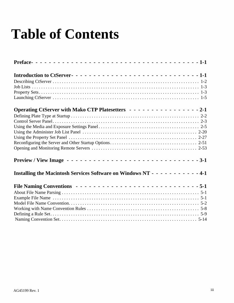
Table of Contents
Preface- - - - - - - - - - - - - - - - - - - - - - - - - - - - - - - - - - - - - - 1-1
Introduction to CtServer- - - - - - - - - - - - - - - - - - - - - - - - - - - - - 1-1Describing CtServer . . . . . . . . . . . . . . . . . . . . . . . . . . . . . . . . . . . . . . . . . . . . . . . . . . . . . . . . . . . . . . . . 1-2Job Lists . . . . . . . . . . . . . . . . . . . . . . . . . . . . . . . . . . . . . . . . . . . . . . . . . . . . . . . . . . . . . . . . . . . . . . . . . 1-3Property Sets . . . . . . . . . . . . . . . . . . . . . . . . . . . . . . . . . . . . . . . . . . . . . . . . . . . . . . . . . . . . . . . . . . . . . . 1-3Launching CtServer . . . . . . . . . . . . . . . . . . . . . . . . . . . . . . . . . . . . . . . . . . . . . . . . . . . . . . . . . . . . . . . . 1-5
Operating CtServer with Mako CTP Platesetters - - - - - - - - - - - - - - - - 2-1Defining Plate Type at Startup . . . . . . . . . . . . . . . . . . . . . . . . . . . . . . . . . . . . . . . . . . . . . . . . . . . . . . . . 2-2Control Server Panel . . . . . . . . . . . . . . . . . . . . . . . . . . . . . . . . . . . . . . . . . . . . . . . . . . . . . . . . . . . . . . . . 2-3Using the Media and Exposure Settings Panel . . . . . . . . . . . . . . . . . . . . . . . . . . . . . . . . . . . . . . . . . . . . 2-5Using the Administer Job List Panel . . . . . . . . . . . . . . . . . . . . . . . . . . . . . . . . . . . . . . . . . . . . . . . . . . 2-20Using the Property Set Panel . . . . . . . . . . . . . . . . . . . . . . . . . . . . . . . . . . . . . . . . . . . . . . . . . . . . . . . . 2-27Reconfiguring the Server and Other Startup Options. . . . . . . . . . . . . . . . . . . . . . . . . . . . . . . . . . . . . . 2-51Opening and Monitoring Remote Servers . . . . . . . . . . . . . . . . . . . . . . . . . . . . . . . . . . . . . . . . . . . . . . 2-53
Preview / View Image - - - - - - - - - - - - - - - - - - - - - - - - - - - - - - 3-1
Installing the Macintosh Services Software on Windows NT - - - - - - - - - - - 4-1
File Naming Conventions - - - - - - - - - - - - - - - - - - - - - - - - - - - - 5-1About File Name Parsing . . . . . . . . . . . . . . . . . . . . . . . . . . . . . . . . . . . . . . . . . . . . . . . . . . . . . . . . . . . . 5-1Example File Name . . . . . . . . . . . . . . . . . . . . . . . . . . . . . . . . . . . . . . . . . . . . . . . . . . . . . . . . . . . . . . . . 5-1Model File Name Convention. . . . . . . . . . . . . . . . . . . . . . . . . . . . . . . . . . . . . . . . . . . . . . . . . . . . . . . . . 5-2Working with Name Convention Rules . . . . . . . . . . . . . . . . . . . . . . . . . . . . . . . . . . . . . . . . . . . . . . . . . 5-8Defining a Rule Set. . . . . . . . . . . . . . . . . . . . . . . . . . . . . . . . . . . . . . . . . . . . . . . . . . . . . . . . . . . . . . . . . 5-9 Naming Convention Set. . . . . . . . . . . . . . . . . . . . . . . . . . . . . . . . . . . . . . . . . . . . . . . . . . . . . . . . . . . . 5-14
AG45199 Rev. 1 iii


Preface
About this ManualThis manual provides instructions on using CtServer Software. The instructions are presented by output device type.
Chapter 1: Introduction to CtServer Introduces the concepts and functions of CtServer and how to launch the application. A typical setup is presented. Property sets are introduced. Major components of CtServer are introduced.
Chapter 2: Operating CtServer with Mako CTP PlatesettersChapter six provides detailed instructions on how to operate a MAKO 2/4/8 CTP, NEWSmatic, or 4matic CTP platesetter.
Chapter 3: Preview / View Image
Chapter 4: Installing the Macintosh Services Software on Windows NT
Chapter 5: File Naming Conventions
AG45199 Rev. 1 v

Not Covered in this Manual• Hardware and software installation.• CtServer remote monitor user information and instruction.• Information about specific imagesetters and platesetters.
Related Documents and References• CtServer Getting Started Guide (AG45090)• CtServer Remote Monitor User Guide (AG45087)• Operator Manual for specific imagesetter and/or platesetter.
DefinitionsOutput Device - This term is used in this document to identify all supported, imagesetters, output devices or platesetters.
RIP - This term is used in this document to identify a Raster Image processor (RIP) application, Workflow or other products responsible for passing data (TIFF images) to the ECRM CtServer.
CtServer - This is the term used to describe this product throughout this document.
Drop Folder - A folder, associated with a Property Set, where TIFF files which are to be output by CtServer are placed. The files placed in the Drop Folder must have a ‘.tif’ (or ‘.eif’ for RamPage images) in the file name and they must be write enabled for CtServer to output them.
TIFF File - A TIFF file is a raster file that conforms to the TIFF 6.0 specification. This specification defines the contents of the file and how it is to be interpreted. CtServer supports the TIFF 6.0 specification with the following restrictions:
1. Compression must be None, CCIT Group 4, Packbits or LZW.2. The data must be 1 bit, (bi-level).3. The data must be padded to be 32 bit aligned.4. The file should be created using multiple strips (not single strip)
with a strip size between 256k and 12 mb.
RAMPage EIF File - An proprietary file format produced by RAMPage systems to interface with CtServer and ECRM imagesetters. The ability to accept these files is optional. It can be enabled in CtServer 5.0 or later with a password and an enabled encryption key.
AG45199 Rev.1vi

Local Mode of Operation - The CtServer workstation is directly attached to the output device, and the operator is using this workstation.
Remote Mode of Operation - When the output device is attached to another workstation on the network, not the workstation the operator is using.
SIF file - Server Information File. This file contains all of the information about the CtServer and the output device.
Terms and Conventions Used in This ManualType To type data at the keyboard.
Select To choose one of several available options in a menu or dialog.
Click To use the mouse button to click on an option or button in a menu or dialog.
> Symbol used to connect menu selections. example view>toolbar.
Enter To type data and then press the Enter key.
Italic typeface Used to indicate the first mention of an important concept.
Bold typeface Used to highlight important details in text or illustrations and to indicate user actions.
Bold sans-serif Used to represent file names or menu options to be selected. Also refers to section names.
Note Blocks of text used to advise of related information.
IMPORTANT Notices used to emphasize very important information.
vii
AG45199 Rev. 1
AG45199 Rev.1
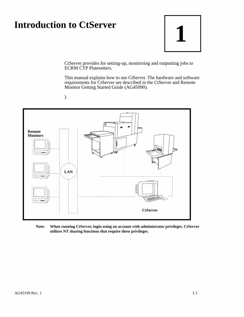
1Introduction to CtServer
CtServer provides for setting-up, monitoring and outputting jobs to ECRM CTP Platesetters.
This manual explains how to use CtServer. The hardware and software requirements for CtServer are described in the CtServer and Remote Monitor Getting Started Guide (AG45090).
).
Note: When running CtServer, login using an account with administrator privileges. CtServer utilizes NT sharing functions that require these privileges.
LAN
CtServer
Remote Monitors
AG45199 Rev. 1 1-1

Describing CtServer A CtServer local server performs all of CtServer’s required setup and monitoring functions, including the following:
• Control Server Panel This panel allows you to monitor the log information, start/stop the server, pause/resume output, set the log policy, and enable/disable property sets.
• Administer Job List Panel This panel allows you to view the list jobs and associated informa-tion (view image, view TIFF tags), pause, resume, rerun, change job properties, change property sets, and delete jobs. CtServer dis-plays information about the progress of each job while processing it.
• Edit or Create Property Set PanelThis panel allows you to define and modify property sets. These property sets define the details of how the image is to be output, positioned and punched/cut. The selections are dependent on the output device.
• Media and Exposure Settings PanelThis panel allows you to send exposure sweeps, set exposure set-tings, and specify currently media for the output device.
• Opening and Monitoring Remote ServersThis function allows you to monitor the jobs that are running on other CtServer Servers on the network.
• Reconfiguring the Server - This function allows you to change specific parameters of the original configuration.
1-2 AG45199 Rev. 1

Job ListsCtServer maintains a list of jobs submitted via drop folders. Each job is associated with a property set, which is a set of output characteristics such as margins and media type. Placing a TIFF file in the drop folder submits that TIFF to CtServer for scheduling and printing using that folder’s associated property set/output characteristics.
Property SetsA property set includes information about job control, including, the drop folder name, job management settings and output device specific settings. Depending on the output device, the following information may be included in the property set:
• Media type and width• Punch settings• Image effects and manipulations• Margin settingsThrough the CtServer user interface, the operator creates property sets that have various job, image and output settings. Each property set has a corresponding drop folder. RIP stations select the property set they
CtServer
RIP station
TIFF files
DropFolder
AG45199 Rev. 1 1-3

require by submitting jobs to the appropriate drop folder.
RIP stations send TIFF files to CtServer by writing the TIFF files to a drop folder over the network. CtServer will recognize the file in the drop folder and place the file into the job list.
The figure below shows a job list display. Double clicking on a job causes the imaging parameters for that job to be displayed in the status bar at the bottom of the screen.
Macintosh Macintosh OS 9 workstations use the Chooser to locate the drop folders on the network and require that the hot folder be on an NTFS partition, which is shared with ‘Services for Macintosh’ via NT 4.0 Server or Windows 2000 Server. PC workstations may use the Network Neighborhood accessory to locate remote directories/drop folders. (See Appendix B for installing Services for Macintosh.)
Note: If NT/2000 Server is not used, an alternative application like PC Mac LAN (by Miramar Systems) must be used to enable Macintosh OS 9 connectivity.
Status Bar
1-4 AG45199 Rev. 1

Launching CtServerTurn on the platesetter (see the operator’s guide). The platesetter must be powered up and showing ONLINE before Windows NT/2000/XP is started. If NT is started before the platesetter is ONLINE, NT will not be able to establish communication with the platesetter. Once the platesetter is online and NT is “booted,” CtServer can be launched.
Local PC To launch CtServer:
1. Click on the CtServer icon on the desktop.2. Or click on Start/Programs/ECRM CtServer.• After a few seconds the screen displays the CtServer Control
Server panel.
For instructional purposes, this panel is divided into three sections. Section one (1) and section two (2) are elements that are common to all panels in CtServer. Section three (3) is a section that varies, depending on the active panel. The different panels are named Control Server, Administer Job List, Edit/Create Property Sets, and Media/Exposure Settings. These panels are described in detail in their respective sections within this document.
menustoolbar
1
2
3
AG45199 Rev. 1 1-5

Panel Section 1
1
Server Status Pane - This section of the CtServer panel gives you an updated status of the local server. It is available on all CtServer Panels.
The server status pane section of any panel contains the following components:
• Images PendingThis value is equal to the number of images that are ready and eligible to be output, times the number of copies for each. This is an indication of the ‘load’ of the system.
• Hide/Show Information Button - The two buttons in the lower right corner (of the small view area) are used to hide/show information by contracting/expanding the window.
• Current Plate and Pin Bar - The names of the plate and the pin bar that are currently in use appear here.
• Image Drive Usage - An easy to read pie chart allows you to visually monitor the disk usage on the image drive. You can also view the numerical image drive use by clicking on the pie chart.
• Plate Supply Indicator - This bar shows the state of the film/plate supply. The bar gets shorter as the supply decreases. On Mako CTP
imaging
pause/resume
image drive
output to recorder
server name
imagespendingtraffic
lightshide/showinformation
usage
progress
statusbar
serverstate
* This indicator bar appears if the imagesetter is a filmsetter or an Automatic platesetter, the bar is replaced by a dynamic text that reports plate supply status. If the imagesetter is a Manual Load Mako CTP platesetter this space
Load Mako CTP platesetter. If the imagesetter is a Tigercat or Wildcat
is left blank. Clicking on this bar displays the percentage of media remaining.
film/platesupply
indicator*
current plateand pin bar
buttons
1-6 AG45199 Rev. 1

platesetters equipped with an autoloader, the indicator also displays the approximate number of plates remaining in the cassette.
• Imaging Progress - The imaging progress bar is a graphical representation that provides feedback on the imaging progress of the currently imaging job. • Pause/Resume Output Button - These two buttons are used to
pause/resume output to the recorder. Selecting the Pause button stops CtServer from outputting additional jobs to the recorder. Jobs will continue to be added to the job list. Jobs in the list will not be processed or output. They will stay in their current state. If a job is outputting when the button is selected that job continues to completion. When outputting is paused, pressing the Resume button resumes the outputting of jobs in the list.
Note: On initial startup of CtServer, Output is Paused. Initial startup and Start Server are the only times when new jobs are not entered into the Job List when Output is Paused.
• Status Bar - When you place your mouse pointer over a button or click on a menu choice, the status bar gives you a brief explanation of the function.
• Server State - This displays a message identifying the state of the server (ex. paused, on-line, operator action).
• Traffic Light & StatusThe Traffic Light, and the associated status, provides constant, up-to-date feedback on what the server is doing and how many images are ready for output. The feedback is both textual and visual. The states and displays are as follows:Red – not running (stopped).Flashing Red - Output device error.Red and Yellow - Paused.Yellow - Warning from server (low disk space, etc.).Flashing Yellow - Warning from output device (no media, etc.)Green - Idle and ready.Flashing Green - Imaging a job.
• Dim (grayed) - Invalid SIF file. This is displayed when a Remote Server Information File (sealion.sif) is invalid, cannot be found or the responsible CtServer is not running.
• Server NameThe title bar of the panel displays the NT name of the server on which the CtServer is running.
AG45199 Rev. 1 1-7

Panel Section 2
2
This section of the panel contains the menu and toolbar options and buttons.
Toolbar
CtServer provides a toolbar for convenient selection of options. To view the toolbar click on view, then toolbar. The toolbar menu item will now be checked. To hide the toolbar click on view, then toolbar a second time (acts as a toggle).
The CtServer toolbar displays buttons that initiate many of CtServer menu options. Click on a button to select it.
Position the mouse over a button to display a popup of the button’s name. A description of the function will also be displayed in the status bar at the bottom of the CtServer window. Buttons for inaccessible options are grayed out on the toolbar, but their names and descriptions still appear.
For example, the Change Media and the Empty Bin toolbar buttons are not available for imagesetters. When an imagesetter is selected as the output device, the Change Media and Empty Bin buttons are grayed out, as shown below.
When the mouse cursor is placed over either an active or an inactive (grayed-out) button, the name of the button is displayed, as shown below.
menu options
toolbar buttons
grayed out buttons
1-8 AG45199 Rev. 1

Icons
Icon Function
For opening a remote server. This button is used to open a window to a remote CtServer. This window will display recorder, server, job and property set information.
For stopping and exiting CtServer.
For accessing the Control Server Panel.
For accessing the Job List Administration Panel.
For accessing the Create/Edit Property Sets Panel.
For accessing the Media and Exposure Settings panel.
For changing the current media. This button is only active for Mako CTP recorders, and only when output to the recorder is paused.
For emptying the slipsheet bin. This button is only active for Mako CTP platesetters equipped with a slipsheet removal system, and only when output to the recorder is paused.
For changing units of measure. Selections are inches, centimeters, millimeters and points.
For information about CtServer.
AG45199 Rev. 1 1-9
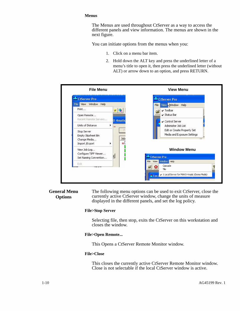
Menus
The Menus are used throughout CtServer as a way to access the different panels and view information. The menus are shown in the next figure.
You can initiate options from the menus when you:
1. Click on a menu bar item.
2. Hold down the ALT key and press the underlined letter of a menu’s title to open it, then press the underlined letter (without ALT) or arrow down to an option, and press RETURN.
General Menu Options
The following menu options can be used to exit CtServer, close the currently active CtServer window, change the units of measure displayed in the different panels, and set the log policy.
File>Stop Server
Selecting file, then stop, exits the CtServer on this workstation and closes the window.
File>Open Remote...
This Opens a CtServer Remote Monitor window.
File>Close
This closes the currently active CtServer Remote Monitor window. Close is not selectable if the local CtServer window is active.
File Menu View Menu
Window Menu
1-10 AG45199 Rev. 1
File>Units of Distance
This item offers a submenu of Inches, Centimeters, Millimeters or Points. The currently selected units will have a check mark. All distance values in CtServer (both local and remote views) display in the selected units.
File>Change Media...
This will initiate the Change Media dialog which is used to change the current media.
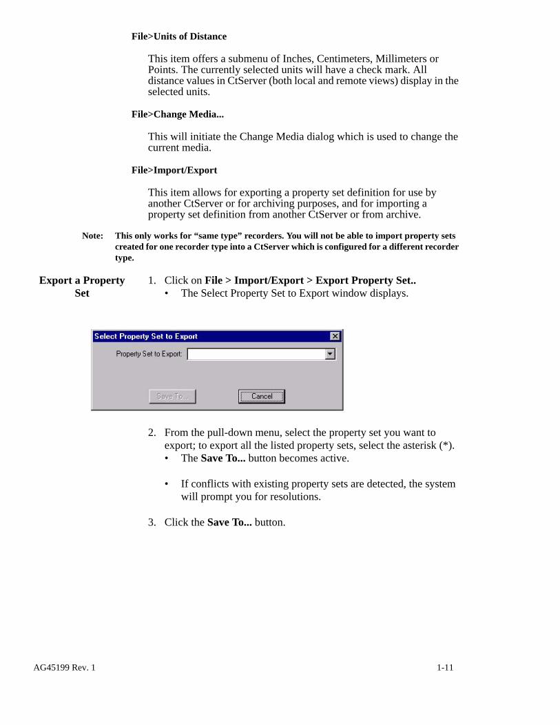
File>Import/Export
This item allows for exporting a property set definition for use by another CtServer or for archiving purposes, and for importing a property set definition from another CtServer or from archive.
Note: This only works for “same type” recorders. You will not be able to import property sets created for one recorder type into a CtServer which is configured for a different recorder type.
Export a Property Set
1. Click on File > Import/Export > Export Property Set..• The Select Property Set to Export window displays.
2. From the pull-down menu, select the property set you want to export; to export all the listed property sets, select the asterisk (*).• The Save To... button becomes active.
• If conflicts with existing property sets are detected, the system will prompt you for resolutions.
3. Click the Save To... button.
AG45199 Rev. 1 1-11

• The “Select Destination Directory...” window displays.
4. Select directory to which the property set(s) are to be exported.5. Click OK.
Note: The following are NOT exported: exposure settings, jobs, WildCat/TigerCat plate data-bases, plate definitions not used in a property set and server configuration settings.
Import a Property Set
1. Click on File > Import/Export > Import Property Set...• The Select Imported Property Set(s) window displays.
2. From the Look In: pull-down list, select the folder that contains the property set you want to import.
3. Select the property set you want to import. (Multiple selections are allowed.)
4. Click OK.Note: The following are NOT imported: exposure settings, jobs, WildCat/TigerCat plate data-
bases, plates definitions that are not used in a property sets and server configuration set-tings
1-12 AG45199 Rev. 1

AG45199 Rev. 1 1-13

1-14 AG45199 Rev. 1
2Operating CtServer with Mako CTP Platesetters
Operating a Mako CTP platesetter with CtServer involves the following:
• Defining Plate Type at Startup• Using the Media and Exposure Settings Panel• Using the Administer Job List Panel• Using the Property Set Panel• Reconfiguring the Server and Other Startup Options• Opening and Monitoring Remote Servers
AG45199 Rev. 1 2-1

Defining Plate Type at StartupManually Loaded Platesetters
Defining Plate Type at StartupWhen the platesetter and CtServer are started, CtServer asks which plate is to be used.
Manually Loaded Platesetters
If you are using a manually loaded platesetter, the Select Plate Type dialog shown at the right will appear.
1. Plate Type. - This combobox offers the list of defined Plates. Select the Plate Type to start using. The associated Pin Bar for that plate will be displayed. When OK is selected, CtServer will start. All jobs that use the selected Plate will be eligible to image.
Cassette Loaded Platesetters
If you using a platesetter that has an autoloader, the Select Plate Type dialog shown below will appear.
1. Plate Type - This combobox offers the list of defined Plates. If the cassette is to be used, select the Plate Type that is currently loaded in the cassette in the platesetter . If Manual Feed is to be used, select the plate to use. The associated Pin Bar for the selected plate will be displayed.
2. Media Source - This combobox offers Cassette or Manual Feed selections. Select the mode to use.
3. Cassette Capacity - Enter the value that represents a full cassette. This value is used to provide media remaining in the cassette infor-mation.
When OK is selected, CtServer will start. The plate information is sent to the platesetter and the operator is requested to verify the selections
“Cassette Capacity” only displays if the platesetter uses acassette withpermanentslipsheets.
2-2 AG45199 Rev. 1

Control Server Panel What this panel does
are what is actually loaded in the platesetter. Once the confirmation is complete, all jobs that use the selected Plate will be eligible to image.
Control Server Panel
What this panel does
The Control Server Panel is used to monitor system messages for the current session and to enable/disable property sets. To access the panel, click on View, and then on Control Server. Or, alternatively, click on the Control Server button on the toolbar.
• The Control Server panel displays
Note: For instructional purposes, the Control Server panel shown below is divided into two (2) sections. Each section is explained below.
1
2
Note: The “Media Remaining” status bar does not appear for manually loaded Mako CTP recorders.
AG45199 Rev. 1 2-3
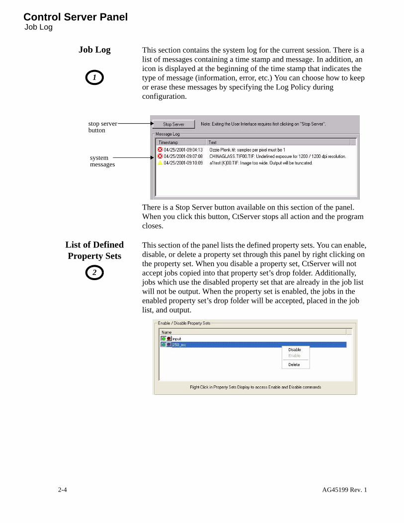
Control Server PanelJob Log
Job Log
1
This section contains the system log for the current session. There is a list of messages containing a time stamp and message. In addition, an icon is displayed at the beginning of the time stamp that indicates the type of message (information, error, etc.) You can choose how to keep or erase these messages by specifying the Log Policy during configuration.
There is a Stop Server button available on this section of the panel. When you click this button, CtServer stops all action and the program closes.
List of Defined Property Sets
2
This section of the panel lists the defined property sets. You can enable, disable, or delete a property set through this panel by right clicking on the property set. When you disable a property set, CtServer will not accept jobs copied into that property set’s drop folder. Additionally, jobs which use the disabled property set that are already in the job list will not be output. When the property set is enabled, the jobs in the enabled property set’s drop folder will be accepted, placed in the job list, and output.
stop serverbutton
systemmessages
2-4 AG45199 Rev. 1

Using the Media and Exposure Settings Panel What this panel does
Using the Media and Exposure Settings Panel
What this panel does
This panel allows you to create plate and pin bar definitions, run exposure sweeps, and change the platesetter’s exposure setting.
1. Click on View, then click on Media and Exposure Settings. Or, alternatively, click on the Media and Exposure Settings button on the toolbar.
• The screen displays the Media and Exposure Settings Panel. This panel contains three (3) tabs: Plates and Bars tab, Exposure Sweep tab, and the Set Exposure tab.
Note: The “Empty Bin” button is only present for automatic- load platesetters that support automatic slipsheet removal.
AG45199 Rev. 1 2-5

Using the Media and Exposure Settings PanelPlates and Bars Tab
Plates and Bars Tab
The Plates and Bars tab displays both the Pin Bar and Plate definitions. These definitions define the characteristics of the Pin Bars and Plates that are used platesetter. This name will be used to identify the Pin Bar or Plate during operation of the system.
1. Click on the Plates and Bars tab.• The screen displays a list of all the Pin Bars defined and a list of
all the Plate Types defined.
2. To add a Pin Bar definition, click on the Add... button. • To edit an existing definition, click on the Pin Bar name and
then click on the Edit... button.
• To delete an existing definition, click on the Pin Bar name and then click on the Delete button.
Note: You will not be allowed to edit a Pin Bar definition that is currently being used in a Plate definition.
2-6 AG45199 Rev. 1
Using the Media and Exposure Settings Panel Plates and Bars Tab
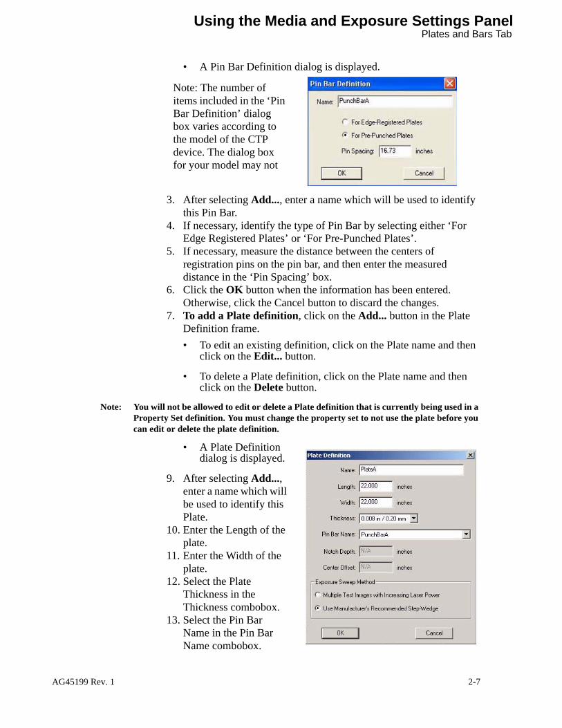
• A Pin Bar Definition dialog is displayed.
3. After selecting Add..., enter a name which will be used to identify this Pin Bar.
4. If necessary, identify the type of Pin Bar by selecting either ‘For Edge Registered Plates’ or ‘For Pre-Punched Plates’.
5. If necessary, measure the distance between the centers of registration pins on the pin bar, and then enter the measured distance in the ‘Pin Spacing’ box.
6. Click the OK button when the information has been entered. Otherwise, click the Cancel button to discard the changes.
7. To add a Plate definition, click on the Add... button in the Plate Definition frame. • To edit an existing definition, click on the Plate name and then
click on the Edit... button.
• To delete a Plate definition, click on the Plate name and then click on the Delete button.
Note: You will not be allowed to edit or delete a Plate definition that is currently being used in a Property Set definition. You must change the property set to not use the plate before you can edit or delete the plate definition.
• A Plate Definition dialog is displayed.
9. After selecting Add..., enter a name which will be used to identify this Plate.
10. Enter the Length of the plate.
11. Enter the Width of the plate.
12. Select the Plate Thickness in the Thickness combobox.
13. Select the Pin Bar Name in the Pin Bar Name combobox.
Note: The number of items included in the ‘Pin Bar Definition’ dialog box varies according to the model of the CTP device. The dialog box for your model may not
Figure 1-8
AG45199 Rev. 1 2-7

Using the Media and Exposure Settings PanelPlates and Bars Tab
• If the selected Pin Bar is an edge register bar, Notch Depth and Center Offset are not enabled.
• If the selected Pin Bar is a punch register bar, Notch Depth and Center Offset are enabled.
14. If the Plate is to be used with a punch register Pin Bar, enter the punch Notch Depth.
15. If the punch notches are not centered on the plate, enter the offset value. Enter a positive value if the punches are offset to the left of the center of the plate (as shown below), or a negative value if they are offset to the right.
110mm
Centerlineof Punches
Centerlineof Plate
110mm
Centerlineof Plate
157mm157mm
110mm
Centerlineof Punches
110mm
157mm 157mm
+25mm
No Offset Offset of +25mm 16. Select your choice of the Exposure Sweep Method to be used to
with the plate. (For more details, see Exposure Sweep Tab on page 2-11.)
17. Click the OK button when the information has been entered.This saves your plate definition and adds it to the list of definitions. Otherwise, click the Cancel button to discard the changes.
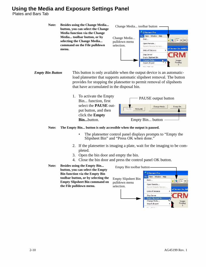
Change Media Button 1. To activate the new plate definition, first select the PAUSE output button, and then click the Change Media...button.
Note: The Change Media... button is only accessible when the output is paused.
• The Select Plate Type window opens.
PAUSE output button
Change Media... button
2-8 AG45199 Rev. 1

Using the Media and Exposure Settings Panel Plates and Bars Tab
For a manual-load Mako CTP, the window looks like this:
For an automatic-load Mako CTP, the window looks like this:
“Cassette Capacity” only displays if the system uses anautoloader with permanentslipsheets.
2. From the Plate Type pulldown list, select the plate type you created a moment ago. (Doing so will also select the associated pin bar).• For an automatic load Mako CTP, also select the Media Source
and Cassette Capacity.
3. Click OK.• For an automatic load Mako CTP, CtServer will send this
information to the platesetter. The platesetter will then prompt the operator to load the appropriate pin bar and/or cassette.
• When CtServer activates the new plate definition, it displays the plate name and bar name associated with the definition in the “Current” definition display area.
.
“CURRENT”DEFINITION
DISPLAYAREA
AG45199 Rev. 1 2-9
Using the Media and Exposure Settings PanelPlates and Bars Tab
Note: Besides using the Change Media... button, you can select the Change Media function via the Change Media... toolbar button, or by selecting the Change Media... command on the File pulldown menu.
Empty Bin Button This button is only available when the output device is an automatic-load platesetter that supports automatic slipsheet removal. The button provides for stopping the platesetter to permit removal of slipsheets that have accumulated in the disposal bin.
1. To activate the Empty Bin... function, first select the PAUSE out-put button, and then click the Empty Bin...button.
Note: The Empty Bin... button is only accessible when the output is paused.
• The platesetter control panel displays prompts to “Empty the Slipsheet Bin” and “Press OK when done.”
2. If the platesetter is imaging a plate, wait for the imaging to be com-pleted.
3. Open the bin door and empty the bin.4. Close the bin door and press the control panel OK button.
Note: Besides using the Empty Bin... button, you can select the Empty Bin function via the Empty Bin toolbar button, or by selecting the Empty Slipsheet Bin command on the File pulldown menu.
Change Media... toolbar button
Change Media...pulldown menuselection.
PAUSE output button
Empty Bin... button
Empty Bin toolbar button
Empty Slipsheet Binpulldown menuselection.
2-10 AG45199 Rev. 1

Using the Media and Exposure Settings Panel Exposure Sweep Tab
Exposure Sweep Tab
The Exposure Sweep tab provides information fields for generating an exposure sweep job. The number and type of fields depends on which exposure sweep method is selected in the plate definition (see page 2-7). The method for setting exposure is dictated by the plate manufacturer. Some manufacturers recommended the Multiple Test Images with Increasing Laser Power method, whereas others recommended the Step Wedge method. Use the method recommended by the manufacturer of the of plate you are using.
Multiple Test ImagesExposure Sweep
1. First set the Current Media as described above and then click on the Change Media button.
Note: The Change Media button will only be enabled when the output is paused. If the button is not enabled, click on the Pause Output button.
2. Click on the Exposure Sweep tab.• The screen displays the Exposure Sweep tab and the
information fields for setting up an exposure sweep job.
3. Click on the down arrow in the Vertical Resolution (dpi) and Magnification (%) information field.• The screen displays a list of resolution and magnification
combinations. All available vertical resolutions are combined with all the vertical magnification values that are currently used in a property set.
Note: The Horizontal and Vertical resolution combo boxes will be empty if no Property Sets are defined. You must define at least one Property Set prior to running an exposure sweep or setting exposure values.
4. Select a value for the resolution/magnification from the list.5. Click on the down arrow in the Horizontal Resolution (dpi) and
AG45199 Rev. 1 2-11

Using the Media and Exposure Settings PanelExposure Sweep Tab
Magnification (%) information field.• The screen displays a list of resolution and magnification
combinations. All available horizontal resolutions are combined with all the horizontal magnification values that are currently used in a property set.
Note: Exposure settings will vary depending on resolution and magnification. In order to iden-tify the optimum exposure setting it is required that the specific resolution/magnification combination be specified.
6. Select a value for the resolution/magnification from the list.7. Click on the Exposure Value of the First Image information field
and enter the value. The exposure value refers to a scale of laser intensity on the imagesetter and the value must be between 0 and 255. A higher value results in a brighter laser and, therefore, a darker image on the film.
8. Click on the Step Exposure By information field to set the expo-sure increments. This value is the amount you want the exposure to change by from one image to the next in the exposure chart.
9. Click on the Exposure Value of Last Image information field to set the value for the last image.
10. Select Negative if you want the exposure sweep image as a negative.
Note: Exposure sweep images are provided for most combinations of horizontal and vertical resolution. If you select a combination that is not available, a warning will be provided and the closest available combination will be used.
11. Click on the Submit Exposure Sweep Job button to begin the exposure sweep job.• CtServer generates and images a job containing a series of
2-12 AG45199 Rev. 1

Using the Media and Exposure Settings Panel Exposure Sweep Tab
grayscale strips that are imaged at exposure values beginning with the first exposure value and incrementing by the step value. The first and last images are at the exposure values you specified, but the exposure change between the last two images may not be the step exposure value if adding the step value to the next-to-last exposure setting would exceed the last value specified
Note: If you do anything that could alter the contents of the resolution and magnification list after making resolution/magnification selections but before running the sweep, CtServer automatically clears your selections as a precautionary measure, and you must reselect them.
12. Process the test plate.13. At locations that correspond to locations 1, 2, 3, and 4 in the next
figure, compare the width of the black and white lines. 14. If the black and white lines are of equal width at all four loca-
tions, the optics in your system are properly focused. If the black and white lines are of unequal width, the focus needs to be adjusted. Call ECRM or your service provider.
Server Exposure Sweep Test
AG45199 Rev. 1 2-13

Using the Media and Exposure Settings PanelExposure Sweep Tab
1
2
3
4
GOOD
Black and white lines
Black line is thicker
Black line is thin-ner
FOCUSIMPROPER
FOCUSIMPROPER
FOCUS
2-14 AG45199 Rev. 1

Using the Media and Exposure Settings Panel Exposure Sweep Tab
Step Wedge Exposure Sweep
The step wedge test is used to calibrate the exposure setting to match the plate and the processor chemistry. The test applies to photopolymer plates only.
The test involves taping a step-wedge test strip on the plate, exposing the plate, and evaluating the resultant test image as explained below. ECRM strongly recommends new processor chemistry be used to process step-wedge test plates.
The figure below shows a step-wedge test strip. It happens to have 15 steps. Some test strips have fewer than 15 steps, whereas others have more. On any given test strip, the first step is virtually clear, the last step is virtually black, and steps in between are of varying density, with each step being darker than the preceding (lower-numbered) step.
When the test strip is taped over the plate, “clear” step 1 allows virtually all of the energy in the imaging beam to hit the plate, step 2 slightly less energy, step 3 still less energy, etc.
On a typical test plate, the lower-numbered wedge steps are completely imaged (very dark), the higher-numbered steps are barely imaged (very light/clear), and one or two transition steps between the dark and light areas are partially imaged.
The distribution of dark steps, transition steps, and light step varies depending on the platesetter’s exposure setting, the plate type being used, and the state of the processor chemistry.
Prepare a plate for the test
1. Obtain a step wedge test strip.Note: ECRM recommends using a Fuji 15-step “T” step wedge test strip
(ECRM PH0388) on Fuji plates, and a Stouffer 21-step wedge (ECRM PH0389) on all other plates.
2. Unload the cassette from the platesetter.
1 2 3 4 5 6 7 8 9 10 11 12 13 14 15
1 2 3 4 5 6 7 8 9 10 11 12 13 14 15
1 2 3 4 5 6 7 8 9 10 11 12 13 14 15
1 2 3 4
56 7 8 9 10 11 12 13 14 1575
AG45199 Rev. 1 2-15

Using the Media and Exposure Settings PanelExposure Sweep Tab
3. Move the cassette to a safelight environment and open the lid.4. Using the plate manufacturer’s recommended step wedge strip,
center the test strip on the plate 6 inches (15.2 cm) back from the leading edge, as shown below. • Be sure to use two pieces of tape.
• Make sure the emulsion side of the step wedge faces the emulsion side of the plate.
5. Close and lock the cassette cover.6. Load the cassette into the platesetter.7. Open the cassette light shield.8. In CtServer, click on the Exposure Sweep tab.
• The screen displays the Exposure Sweep tab and the information fields for setting up an exposure sweep job.
STEP WEDGE
Centerline of Plate6 inches
TAPE
TAPE
Leading Edge of Plate
15.2 cm
TEST STRIP
Front ofCassette
Left Sideof Cassette
2-16 AG45199 Rev. 1

Using the Media and Exposure Settings Panel Exposure Sweep Tab
9. Click on the down arrow in the Vertical Resolution (dpi) and Magnification (%) information field.• The screen displays a list of resolution and magnification
combinations. All available vertical resolutions are combined with all the vertical magnification values that are currently used in a property set.
Note: The Horizontal and Vertical resolution combo boxes will be empty if no Property Sets are defined. You must define at least one Property Set prior to running an exposure sweep or setting exposure values.
10. Select a value for the resolution/magnification from the list.11. Click on the down arrow in the Horizontal Resolution (dpi) and
Magnification (%) information field.• The screen displays a list of resolution and magnification
combinations. All available horizontal resolutions are combined with all the horizontal magnification values that are currently used in a property set.
Note: Exposure settings will vary depending on resolution and magnification. In order to iden-tify the optimum exposure setting it is required that the specific resolution/magnification combination be specified.
12. Select a value for the resolution/magnification from the list.13. Click on the Exposure Set-Wedge at Laser Power of: information
field and enter the value. The exposure value refers to a scale of laser intensity on the imagesetter and the value must be between 0 and 255. A higher value results in a brighter laser and, therefore, a darker image on the film.
14. Click on the Submit Exposure Sweep Job button to begin the exposure sweep job The system exposes the first 8 inches of the plate with 100% laser light at the exposure setting selected. After exposure, the plate moves onto the transport belt and advances until the leading edge of the plate is detected by the transport exit sensor. The transport then stops, the warning light on the top cover flashes, and a prompt to open the transport cover and remove the step wedge displays on the control panel.
15. Making sure to maintain safelight conditions — which may require you to use a large a large black cloth to cover the transport unit — lift up the transport top cover and remove the taped-on step wedge.
16. Set the transport cover down, back into place.Note: Note: In step wedge test pattern mode, the machine will not beep or report cover inter-
lock open messages.
17. On the front panel, press OK. The transport feeds the plate into the processor.
18. Process the plate.19. Evaluate the output as explained in the next section.
AG45199 Rev. 1 2-17
Using the Media and Exposure Settings PanelExposure Sweep Tab
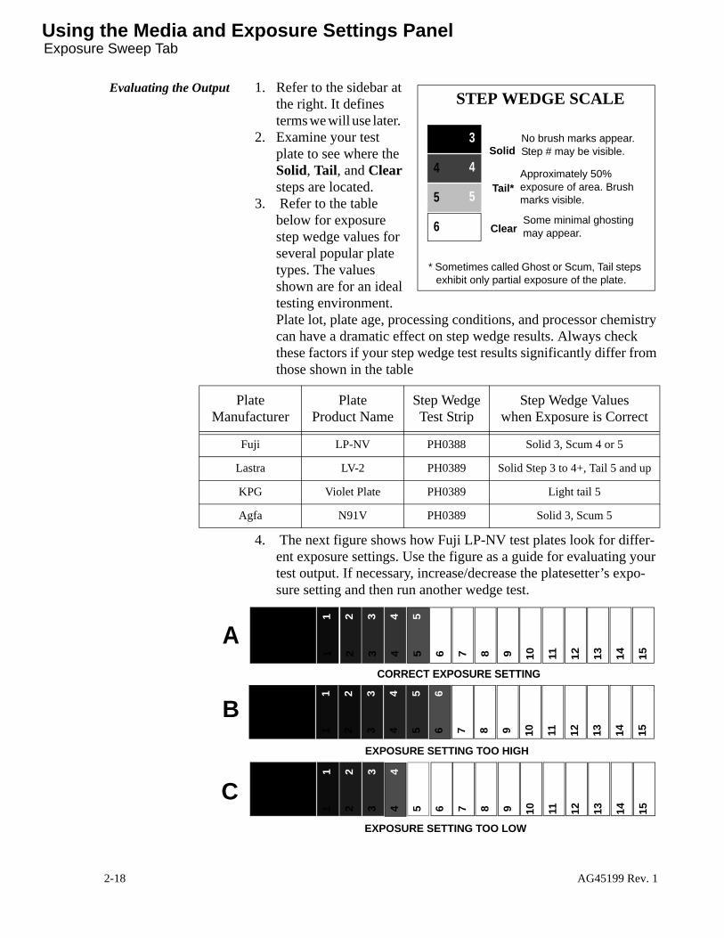
Evaluating the Output 1. Refer to the sidebar at the right. It defines terms we will use later.
2. Examine your test plate to see where the Solid, Tail, and Clear steps are located.
3. Refer to the table below for exposure step wedge values for several popular plate types. The values shown are for an ideal testing environment. Plate lot, plate age, processing conditions, and processor chemistry can have a dramatic effect on step wedge results. Always check these factors if your step wedge test results significantly differ from those shown in the table
4. The next figure shows how Fuji LP-NV test plates look for differ-ent exposure settings. Use the figure as a guide for evaluating your test output. If necessary, increase/decrease the platesetter’s expo-sure setting and then run another wedge test.
3
4
5
6
23
4
5
6
Solid
Tail*
Clear
No brush marks appear. Step # may be visible.
Approximately 50% exposure of area. Brush marks visible.
Some minimal ghosting may appear.
STEP WEDGE SCALE
* Sometimes called Ghost or Scum, Tail steps exhibit only partial exposure of the plate.
Plate Manufacturer
Plate Product Name
Step WedgeTest Strip
Step Wedge Values when Exposure is Correct
Fuji LP-NV PH0388 Solid 3, Scum 4 or 5
Lastra LV-2 PH0389 Solid Step 3 to 4+, Tail 5 and up
KPG Violet Plate PH0389 Light tail 5
Agfa N91V PH0389 Solid 3, Scum 5
1 2 3 4 5 6 7 8 9 10 11 12 13 14 15
1 2 3 4 5 6 7 8 9 10 11 12 13 14 15
1 2 3 4 5 6 7 8 9 10 11 12 13 14 15
1 2 3 4 5 6 7 8 9 10 11 12 13 14 15
1 2 3 4 5 6 7 8 9 10 11 12 13 14 15
1 2 3 4 5 6 7 8 9 10 11 12 13 14 15
EXPOSURE SETTING TOO LOW
EXPOSURE SETTING TOO HIGH
CORRECT EXPOSURE SETTING
C
A
B
2-18 AG45199 Rev. 1
Using the Media and Exposure Settings Panel Set Exposure Tab
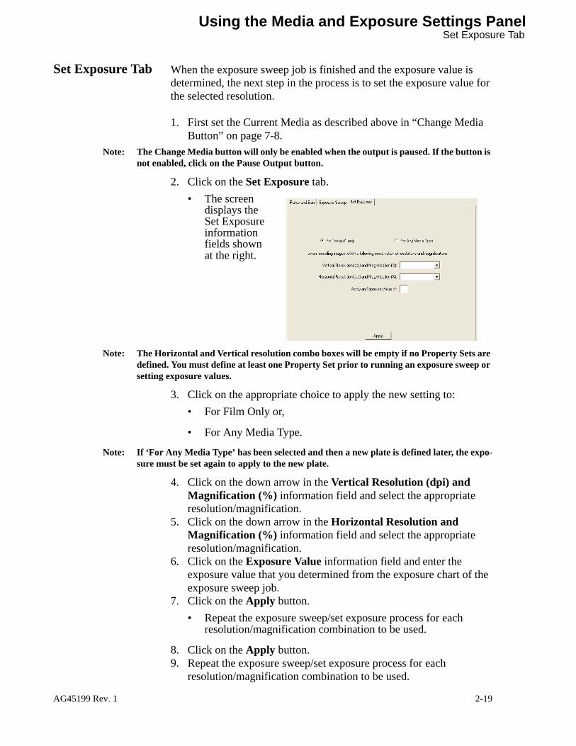
Set Exposure Tab When the exposure sweep job is finished and the exposure value is determined, the next step in the process is to set the exposure value for the selected resolution.
1. First set the Current Media as described above in “Change Media Button” on page 7-8.
Note: The Change Media button will only be enabled when the output is paused. If the button is not enabled, click on the Pause Output button.
2. Click on the Set Exposure tab.• The screen
displays the Set Exposure information fields shown at the right.
Note: The Horizontal and Vertical resolution combo boxes will be empty if no Property Sets are defined. You must define at least one Property Set prior to running an exposure sweep or setting exposure values.
3. Click on the appropriate choice to apply the new setting to:• For Film Only or,
• For Any Media Type.
Note: If ‘For Any Media Type’ has been selected and then a new plate is defined later, the expo-sure must be set again to apply to the new plate.
4. Click on the down arrow in the Vertical Resolution (dpi) and Magnification (%) information field and select the appropriate resolution/magnification.
5. Click on the down arrow in the Horizontal Resolution and Magnification (%) information field and select the appropriate resolution/magnification.
6. Click on the Exposure Value information field and enter the exposure value that you determined from the exposure chart of the exposure sweep job.
7. Click on the Apply button.• Repeat the exposure sweep/set exposure process for each
resolution/magnification combination to be used.
8. Click on the Apply button.9. Repeat the exposure sweep/set exposure process for each
resolution/magnification combination to be used.
AG45199 Rev. 1 2-19

Using the Administer Job List PanelWhat this panel does
Using the Administer Job List Panel
What this panel does
This panel contains the job list administration function. You can view the job list by selecting View> Administer Job List or using the toolbar. This panel is used to manage the list of jobs to be output. You can use the controls provided to manipulate the jobs. After CtServer images a file on the output device, it eventually deletes the file from the job list unless the property set is configured to save the file. CtServer also saves jobs that have errors. Once a job has been deleted, its entry is removed from the display.
1. Click on View, then Administer Job List or click on the Administer Job List button on the toolbar.• The screen
displays the Administer Job List panel.
For instructional purposes this panel is divided into four (4) sections. Section one (1) contains the job command buttons that are available for the selected job(s). Section two (2) contains the job list. Section three (3) contains job command functions available for the selected job(s). Section four (4) contains the job list filter buttons.
1
2
3
4
2-20 AG45199 Rev. 1

Using the Administer Job List Panel Job Command Buttons
Job Command Buttons
1
The Job Command Buttons
Section 1 of the panel provides a set of buttons for frequently used functions, when a job in the job list is selected. Click on a job, then click on the button. CtServer performs the function of the button you click. These buttons are enabled/disabled depending on the state of the selected job (see note below). The buttons available are listed below.
Click on one or more jobs, then click on the button to:
• Pause button - Pauses an eligible job. • Resume button - Resumes a paused job.• Re-Run button - Re-runs a completed, aborted or errored job.• Delete button - Deletes a paused, done, delete pending, error or
aborted job from the list.Note: These buttons will also function when more than one job is selected. However, the
selected command will only be applied to selected jobs that are in the appropriate state.
The Job List This section of the Panel contains the list of jobs that are in the server queue. Additional columns of information are provided for each job to assist job management.
• IconsThere are three columns of icons that are provided to assist in identifying the status of jobs in the job list. They are displayed to the left of the job name.
job name property set time stamp status ofjob
sort by.
Note: The column width can be changed by dragging the end of the column.
three columnsof icons
plate name[pin bar name]
completed image
imaging
pause
? error
pendingblankspace
already imaged orwhite
greeneligible to imageyellowineligible to image
higher than
lower than
blankspace normal priority
normal priority
normal priority
abort
disabledproperty set
due to mediamismatch
paused/disabled
COLUMN 1 COLUMN 2 COLUMN 3
AG45199 Rev. 1 2-21

Using the Administer Job List PanelThe Job List
Note: You can display/hide a key to the icons on the screen by clicking Help > Key to Job List Symbols.
• Job Name - This information field is the filename of the job. When you click on the column title button labeled “Jobs”, you can change the way the job list is sorted. You can sort:
1. in output order (based on timestamp of jobs)
2. reverse output order
3. by name, A..Z
4. by name, Z..A• Plate - This information field contains the name of the plate and
the pin bar assigned to the job. When you click on the column title button labeled “Plate”, you can change the way the job list is sorted. You can sort:
5. by plate, A..Z
6. by plate, Z..A• Property Set - This information field is the property set assigned
to the job. When you click on the column title button labeled “Property Set”, you can change the way the job list is sorted. You can sort:
7. by property set, A..Z
8. by property set, Z..A• Time stamp - This information field is the time that the job is
discovered by CtServer. When you click on the column title button labeled “Time Stamp”, you can change the way the job list is sorted. You can sort:
9. oldest first
10. newest first• Status - This information field is the current status of the job. when
you click on the column title button labeled “Status”, you can change the way the job list is sorted. You can sort:
11. by status
12. by reverse statusNote: Although you can change the viewing order as described above, the output order of the
jobs always remain the same. Eligible jobs are output on a first come first serve basis, within a priority.
2-22 AG45199 Rev. 1

Using the Administer Job List Panel Job List Commands
Job List Commands
3
These commands are available by right clicking on a specific job. The drop down commands are grayed if that particular command does not apply to the job you have selected. The choices that are non-grayed are the choices available, at that time, for a specific job. The choices available are determined by the state of the job. For example, you cannot delete a job unless it is paused.
Note: When multiple jobs are selected, only those commands which may be applied to more than one job at a time are available. These commands include: View Image, Pause, Resume, Priority setting, Re-run, Retain and Delete. A command will only be applied to the selected jobs which are in the appropriate state for that command. Jobs that are not in the appropriate state, will not have the command applied. No warning message will be reported when a command is not applied to a job.
1. Right click on a job from the list and the command menu displays.2. Select the desired command.
View TIFF Tags This command allows you to view a detailed TIFF tags report on the file you select. Right clicking on a job and selecting View TIFF Tags displays the report.
1. Clicking on a “+” will dis-play adid-tional information in the report.
2. Clicking on the Save Report button will present a Save As dialog where the loca-tion and filename can be specified and the report saved.
3. Clicking on the Close button will close the report window.
AG45199 Rev. 1 2-23
Using the Administer Job List PanelJob List Commands
This report is useful when trying to determine the cause of TIFF format related problems. The TIFF tags report will also display the resolution and dimensions of the original image.
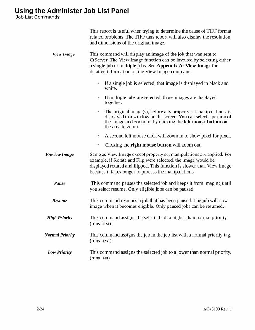
View Image This command will display an image of the job that was sent to CtServer. The View Image function can be invoked by selecting either a single job or multiple jobs. See Appendix A: View Image for detailed information on the View Image command.
• If a single job is selected, that image is displayed in black and white.
• If multiple jobs are selected, those images are displayed together.
• The original image(s), before any property set manipulations, is displayed in a window on the screen. You can select a portion of the image and zoom in, by clicking the left mouse button on the area to zoom.
• A second left mouse click will zoom in to show pixel for pixel.
• Clicking the right mouse button will zoom out.
Preview Image Same as View Image except property set manipulations are applied. For example, if Rotate and Flip were selected, the image would be displayed rotated and flipped. This function is slower than View Image because it takes longer to process the manipulations.
Pause This command pauses the selected job and keeps it from imaging until you select resume. Only eligible jobs can be paused.
Resume This command resumes a job that has been paused. The job will now image when it becomes eligible. Only paused jobs can be resumed.
High Priority This command assigns the selected job a higher than normal priority. (runs first)
Normal Priority This command assigns the job in the job list with a normal priority tag. (runs next)
Low Priority This command assigns the selected job to a lower than normal priority. (runs last)
2-24 AG45199 Rev. 1

Using the Administer Job List Panel Job List Commands
Change Attributes This choice enables you to modify the properties for the job. The original properties are based on the property set assigned to the job when it was submitted. You can modify the properties for the selected job, while maintaining the original property set settings, by selecting Change Attributes. The figure below shows the “Place” change attributes panel.
After selecting the desired settings, click the “OK” button to save the changes.
Note: When the OK button is clicked after changing the job attributes, the job will automati-cally be resubmitted and be eligible to run unless the Pause Job checkbox is checked.
When the job properties have been changed, the job list shows the original property set name preceded by an asterisk (*).
Move This choice allows you to move a job to a new property set. CtServer assigns the job the properties defined in the selected property set. Clicking on Move displays a dialog box. Click on the down arrow and select the name of the property set. Click the “OK” button to save the change.
Abort Stops the currently imaging job.
Re-Run job This command allows you to re-image the selected job when its status is done, delete pending, errored or aborted. You can also specify the number of copies you want by filling in the information field in the dialog box and clicking OK.
AG45199 Rev. 1 2-25

Using the Administer Job List PanelJob List Filter Buttons(
Retain Job This command transforms a delete pending job into a job with a status of done, and keeps it from being automatically deleted.
Delete Job This command deletes a job from the job list. You can not delete a job when it is pending, copying or imaging. To delete a pending job first click on pause, then click on delete.
Job List Filter Buttons(
4
These buttons are used to filter the jobs displayed in the job list. If you have many jobs in the job list, it may difficult to find and monitor the status of specific jobs. To simplify this, job list filters have been provided. There are seven (7) filter buttons.
No Filter Clicking this button shows all jobs in the job list.
Active Clicking this button shows all active jobs. An active job is currently imaging or eligible to image.
Paused Clicking on this button shows all jobs that have not been imaged and are not eligible to image. This includes jobs that have been paused, jobs that are ineligible due to a media mismatch and jobs that belong to a property set that has been disabled.
Finished Clicking on this button shows all jobs that have imaged.
Errors Clicking on this button shows all jobs that have an error or were aborted by the operator.
By Property Set This displays all jobs in the selected property set. To perform this filter, click on the By Property Set button. Then click on the down arrow button to the right. A selectable list of property set names will appear to the left. Select the desired property set.
Note: Filtering by property sets is similar to viewing the individual queues in previous versions of CtServer.
By Plate Name This displays all jobs that specify the selected plate names. To perform this filter, click on the By Plate Name button. Then click on the down arrow button to the right. A selectable list of plate names will appear to the left. Select the desired plate name.
2-26 AG45199 Rev. 1

Using the Property Set Panel What this panel does
Using the Property Set Panel
What this panel does
The Property Set Panel allows you to create, select, view, or modify property sets.
All of these actions are initiated by selecting either a property set or the default values, followed by viewing or editing the values, and finally saving the modified values as a new property set or replacing the values of the current property set.
When creating a new property set, start by selecting the property set that most closely resembles the one you want to create. If no other property sets are defined, or none of the defined sets are similar to the one you want to create, start with the default values. When you have completed your edits, use the Save As button to save to a new property set name.
When editing an existing property set select the property set you wish to edit. When you have completed your edits, use the Save button to replace the property set values with the new values.
When you have selected the property set to start with (default or an existing property set) the information fields are filled in with the appropriate values.
1. Click on View, then Create or Edit Property Sets. (Or, click on the Property Set button on the toolbar to enter the first screen of the property set panel.)
AG45199 Rev. 1 2-27

Using the Property Set PanelOpen Existing Property Set List
• The screen displays the property set panel.
Open Existing Property Set List
1
This section of the property set panel provides a list of property sets to choose from in the open existing property set information field.
• The Open Existing Property Set field contains a selectable list of property set names. Once a property set has been selected, its name is displayed and the property set values are updated to reflect the selected property set. The Save, Save As… and Delete buttons are enabled at this time.
1. Click on the Open Existing Property Set field arrow.• The screen displays a list of existing property sets in a drop
down combobox.
2. Select a property set name from the list.• All of the appropriate information fields are automatically filled in
with the parameters of the selected property set.
1
2
3
2-28 AG45199 Rev. 1

Using the Property Set Panel Editing Command Buttons
• The screen displays the Enqueue tab when a property set is selected.
choosing a propertyset fills in this field
graphical presentation ofproperty set named input
• If you do not want to use an existing property set, set the values to default and begin editing the values.
3. Click on the Set Values to Defaults button.• The screen displays the tabs containing default settings, which
require the operator to enter desired values.
Editing Command
Buttons
2
This section of the property set panel consists of four buttons at the bottom of the panel. If a button is grayed, it is not available for use in the editing functions for the property set you are working on. The buttons are listed below with their explanations.
Save The save button saves any changes to the currently selected property set. This button is enabled when a property set name is selected in the Open Existing Property Set information field.
Save As... The Save As button is enabled when the set values to default button has been used or an existing property set has been selected. When Save As is used, a Save As dialog box is displayed. This is where you assign a new property set name. When you create a property set name, choose a name that indicates the important parameters of the set. This helps operators choose which property set to use for their jobs.
AG45199 Rev. 1 2-29
Using the Property Set PanelEditing Command Buttons
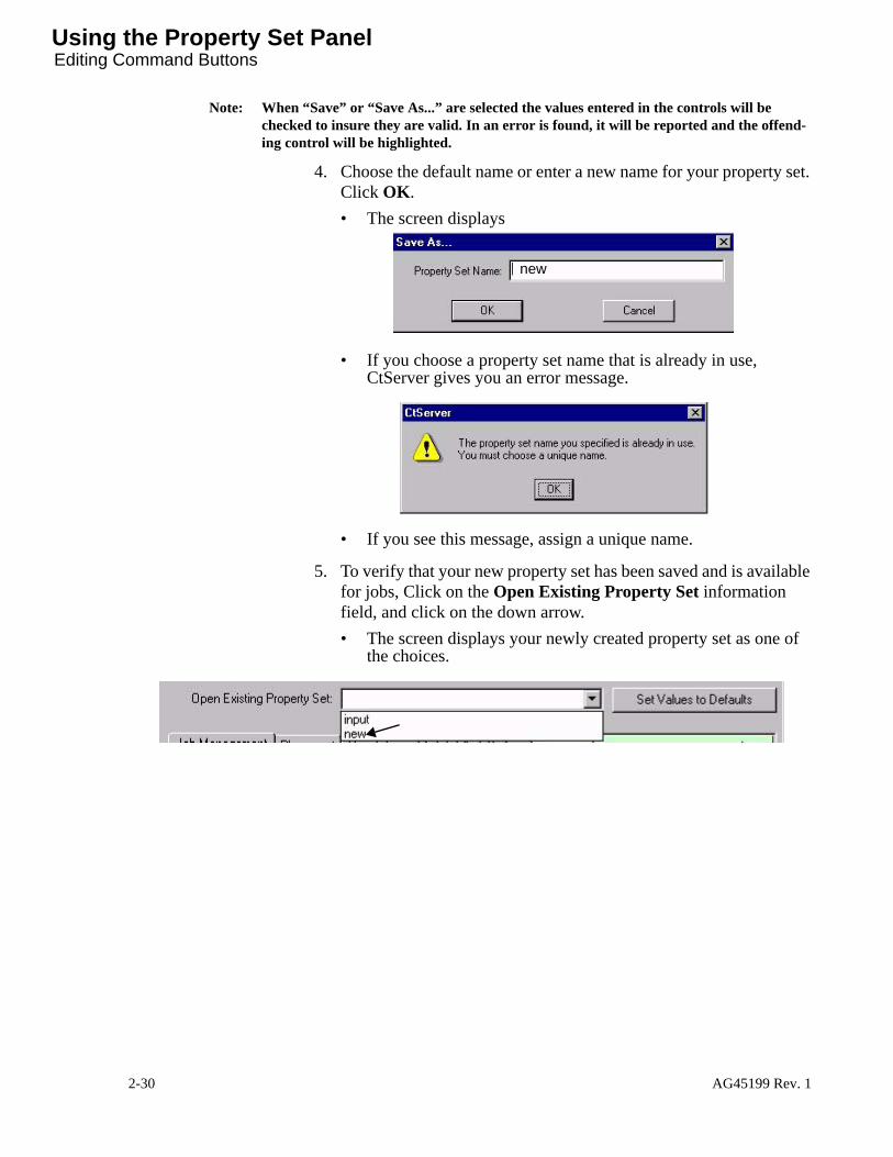
Note: When “Save” or “Save As...” are selected the values entered in the controls will be checked to insure they are valid. In an error is found, it will be reported and the offend-ing control will be highlighted.
4. Choose the default name or enter a new name for your property set. Click OK.• The screen displays
• If you choose a property set name that is already in use, CtServer gives you an error message.
• If you see this message, assign a unique name.
5. To verify that your new property set has been saved and is available for jobs, Click on the Open Existing Property Set information field, and click on the down arrow.• The screen displays your newly created property set as one of
the choices.
new
2-30 AG45199 Rev. 1

Using the Property Set Panel About the Property Set Dialog Tabs
About the Property Set Dialog Tabs
3
The property set dialog tabs are used to view or edit property set values. The tabs are named Enqueue, Image, Place, Magnify, Punch, and Media. As you change the values a graphical presentation is displayed to the right of the property set tab that contains these values.
left margin
top margin value
left margin valueor centered
job image image mediamodify
tabenqueue
tabplacetab
typetab
magnifyimagetab
or centered
markstab
punchsetup
AG45199 Rev. 1 2-31

Using the Property Set PanelEnqueue Tab
Enqueue Tab The Job Enqueue tab is the first set of information fields in the property set panel. The information fields are listed below.
1. Click on Image N Copies of Each information field and enter a value. This sets the number of copies of each job to be imaged. It is useful in a shop that requires multiple films/plates of the same image for proofing or multiple presses.
2. Select an Initial Job State. This selection determines the initial state of incoming jobs. Four (4) choices are available. • Ready will copy the job to the image drive and put it into an
eligible to output state.
• Paused will place the job in a paused state after it has been copied to the image drive. This is useful when the operator wants to manually control the output of each job.
• Copy Paused will put the job into a paused state prior to copying it to the image drive. This is useful for unknown jobs where image manipulations, such as rotation, may be required.
• Copy Paused then Paused will pause the job prior to copying it to the image drive and pause it again after it is copied to the image drive. This is useful for jobs where image manipulations may be required and the operator wants to manually control the output of each individual job.
Note: Image manipulations such as rotation and cropping are performed while the job is being copied to the image drive. Therefore, if they are changed, the job will be recopied.
3. Click on the Keep Jobs after they have been imaged checkbox if you wish to save imaged jobs. This item saves the jobs in the job list after successful output. This may be used by a shop that prefers to visually check each image prior to its deletion.
Local Drop Folder 1. If the drop folder is local to this computer, click on the Path of Shared Directory information. This field contains the property
2-32 AG45199 Rev. 1

Using the Property Set Panel Enqueue Tab
set’s drop folder. You may enter a directory name and location that does not yet exist: in this case CtServer creates the directory when the job administration starts. It is helpful to choose a path whose name indicates the important parameters of the property set. Jobs placed in this folder will be submitted to CtServer and assigned the Property Set associated with the folder.
2. Click on the Share Directory As information field. This defines the name by which the folder is shared over the network. This name is automatically generated from the path. However, you can change it. It is helpful to choose a name that indicates the important param-eters of the property set.
Remote Drop Folder The Remote Drop Folder allows for a drop folder to be on another computer on the local area network (LAN).
1. If the drop folder is to be located on another computer, click on The Drop Folder is Hosted on Another Computer checkbox. This item will display a Browse button which can be used to navigate the network and select the remote folder.
2. Navigate the network to locate and select the remote drop folder.3. Select the Local Volume to use for this Drop Folder’s Mirror
Directory. Then select OK. If you are finished entering property set values:
Click on the Save button to save the changes to the selected property set.
Or click on the Save As button to save the changes to a new property set name.
AG45199 Rev. 1 2-33

Using the Property Set PanelImage Tab
Image Tab The Image Tab in the Property Set dialog Panel enables you to modify the image. Available functions include cropping the image, changing the image polarity, rotating the image 90 degrees or flipping the image. Click on the units buttons to select the desired unit of measurement before you enter a value in the crop origin, width or height fields.
1. Click on the Image tab.• The screen displays the job image manipulation tab.
Cropping of Image You may crop an image on any side, or combination of the four sides.
1. Click the Crop Image checkbox to enable the cropping function.• The top and left sides are cropped by Checking Crop Image
and specifying the distance, in Left Origin and/or Top Origin, from the original edge of the image to the desired edge.
• The bottom and right sides of the image are cropped by specifying a crop on the opposite side (specify 0 if you do not want to crop the Left or Top), clicking the appropriate check box for Limit Image Width to and/or Limit Image Height to and specifying the distance.
F
original image
cropped image
top origin
image width
image height
left origin
2-34 AG45199 Rev. 1
Using the Property Set Panel Image Tab
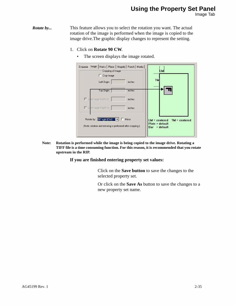
Rotate by... This feature allows you to select the rotation you want. The actual rotation of the image is performed when the image is copied to the image drive.The graphic display changes to represent the setting.
1. Click on Rotate 90 CW.• The screen displays the image rotated.
Note: Rotation is performed while the image is being copied to the image drive. Rotating a TIFF file is a time consuming function. For this reason, it is recommended that you rotate upstream in the RIP.
If you are finished entering property set values:
Click on the Save button to save the changes to the selected property set.
Or click on the Save As button to save the changes to a new property set name.
AG45199 Rev. 1 2-35

Using the Property Set PanelMarks Tab (optional)
Marks Tab(optional)
Printers Marks is an optional feature that can be purchased for CtServer version 5.0 and later. It is enabled via an activation password and an enabled encryption key (dongle).
The Marks Tab is available if the Printers Marks feature has been enabled.
This feature enables the addition of user-created marks (fiducials, etc.) to the image. The user creates marks tiff files at the appropriate resolutions. These files are merged with the image file and then imaged on the plate.
Since the image is overlaid on the marks file, the marks file must be larger (length and/or width) than the image file to insure that the image does not obscure the marks. Also, the marks file must be of same resolution as the image. If it is not, the job will generate an error on output.
1. Click on the Marks tab.• The screen displays the Printers Marks tab.
Printers Marks Set Name
If Printers Marks are to be applied, select the marks set name to use in the combobox. The list of marks set names is based on the Marks sets created during initial installation and configuration or during
MARKSTIFF FILE
IMAGETIFF FILEOverlaid
Circus Poster, Union Graphics
on MARKS file
Text
MARKS file
Fiducials
MARKS filein
in
2-36 AG45199 Rev. 1

Using the Property Set Panel Marks Tab (optional)
reconfiguration. The user must have created sets of marks and populated those sets with TIFF files of the resolutions to be used.
Job and Marks must always be of same color
If the box is checked, a cyan job must use a cyan marks file, a yellow job a yellow marks file, etc. If the box is checked and no correspondingly colored marks file exists for a job, an error will be reported when the job is copied to the image drive. If the box is not checked, CtServer will determine if a correspondingly colored marks file exists for a job. If it does, CtServer will use that marks file for the job. If no correspondingly colored marks file exists, CtServer will look for a marks file that has no color specified.
Note: To create a “no-color” job and/or a matching “no-color” marks file, select “mono-chrome” output in the ECRM TIFF plug-in for the RIP. You can also a use a non-ECRM TIFF plug-in to create such file(s).
Image Placement Relative to Marks
This dialog allows you set the placement of image file over the marks file
Left Offset – By selecting Left Offset from the popup menu/combobox you are able to specify a left offset value for placing the job image on the marks image.
1. Click on the Left Offset information field and enter a value.• The screen displays the entered values.
Top Offset – By selecting Top Offset from the popup menu/combobox you are able to specify a top offset value for placing the job image on the marks image.
1. Click on the Top Offset information field and enter a value.The screen displays the entered values.
Center Horizontally - By selecting the popup menu/combobox you can select Center Horizontally. When this is selected, the value entry is grayed and the job image is centered on the marks image.
1. Click on Center Horizontally.• The screen displays the choice.
Center Vertically - By selecting the popup menu/combobox you can select Center Vertically. When this is selected, the value entry is grayed and the job image is centered on the marks image.
1. Click on Center Vertically.
AG45199 Rev. 1 2-37

Using the Property Set PanelMarks Tab (optional)
• The screen displays the choice.
If you are finished entering property set values:
Click on the Save button to save the changes to the selected property set, or
click on the Save As button to save the changes to a new property set name.
2-38 AG45199 Rev. 1

Using the Property Set Panel Punch Tab
Punch Tab The Punch feature provides for creating, editing and deleting punch set-up definitions that control how and where the platesetter punches registration notches in the plate. The feature supports creation of both simple and complex punch set-ups.
Simple Set-up Definitions
A simple set-up definition effects the punching of either two, one, or no notches in the plate. A simple set-up definition is comprised of one set of these four set-up parameters:
• Lead Notch - The plate punch has four punch elements. Element 1 is the first element the plate passes under; it then passes under Elements 2, 3, and 4, in that order. The Lead Notch parameter is used to define which element will be used to punch the lead notch. Typically, 3 (punch Element 3) or 4 (punch Element 4) is the best setting.
• Trail Notch - is used to define which punch element will punch the trail notch. Typically, 1 or 2 is the best setting.
Setting a notch parameter to “none” disables punching of the notch
• Press Pin Spacing - the distance between the center of the lead notch and the center of the trail notch.
• Center Offset - The offset of the press pin spacing away from the center of the plate. A negative (-) offset shifts the press pin spacing toward the leading edge. A positive (+) offset shifts it toward the trailing edge. Zero (0) offset value keeps the press pin spacing centered on the center of the plate.
This feature only pertains to platesetters that are equipped with a plate punch.
Center of Plate
157mm157mm
Center ofPress Pin Spacing
157mm 157mm
+25mm
No Offset Offset +25mm
220mm
Center ofPress Pin Spacing
Press Pin Spacing 220mm
Press Pin Spacing
Center of Plate
LeadNotch
TrailNotch
LeadNotch
TrailNotch
AG45199 Rev. 1 2-39

Using the Property Set PanelPunch Tab
Complex Set-up Definitions
A complex set-up definition effects the punching of as many as 8 notches in the plate. Every complex set-up definition is comprised of four sets of set-up parameters, each of which effects the punching of two, one, or zero notches in the plate. In the complex set-up definition that produced the punching shown below, one set of set-up parameters produced punch pattern A, a second set produced B, and a third set produced C. The fourth set of parameters was set null to effect no punching.
The “default” set-up The first time you access the Punch feature, the “default” punch set-up will be the only set-up that exists. “Default” is a simple set-up definition in which all the parameters are set to null values. Each null setting is basically a “take no action” command for that particular parameter. Accordingly, because none of its parameters effect any action, “default” is effectively a punch set-up definition for performing no punching.
212mm (+24mm offset)
126mm (+41mm offset)
38mm
B
C
A
Center
Leading Edgeof Plate
Trailing Edgeof Plate
of Plate
340mm
Complex Punch Set-up
(-60mm offset)(+60mm offset)
2-40 AG45199 Rev. 1

Using the Property Set Panel Punch Tab
Creating a simple punch set-up
You can use the “default” set-up definition as template to create a simple punch set-up of your own. Here’s how.
1. In the Property Set panel, click on the Punch tab.• The Punch Pane opens.
2. In the Open Existing Property Set pull-down list, select the prop-erty set that will be associated with the punch set-up you are about to create.
3. If the Punch Set-Up Name window is blank, open the pull-down list and select “default.”
4. Click the View/Edit button.• If the default punch set-up definition is selected, a window like
this opens.
You will now edit this window to create a new set-up definition.
5. At the top of the window, fill in the four fields with values for the new set-up you want to create. For example, to create a set-up for
Punch Tab
Punch Pane
Open ExistingProperty Set:
AG45199 Rev. 1 2-41

Using the Property Set PanelPunch Tab
406mm press pin spacing that is centered on the plate and uses punch Element 4 to punch the lead notch and Element 1 to punch the trail notch, you would fill in the fields as shown below.
6. After you enter your values, click on Save As...
• The Save As... dialog box shown above opens.
7. Enter your choice of a name for the set-up. For example, we named our set-up 406_4_1_centered, as shown above.
8. Click OK. This saves the new set-up name and adds it to the list of available set-ups.• The Punch pane shown on page 35 appears again, with
“default” still selected as the Punch Set-up.
9. Pull down the Page Set-up Name list and highlight the new 406_4_1_centered definition to make it the active punch-set up.
Save As...
2-42 AG45199 Rev. 1

Using the Property Set Panel Punch Tab
Creating a complex punch set-up.
1. If this is the first complex set-up definition you are creating, open the “default” Punch Set-up Definition window as explained in page 2-41, and then click on the Additional Punches button. • The definition window will be expanded as shown below to
allow creation of three more parameter sets for the definition.
If previously created complex punch set-up definitions exists, especially one you could easily edit to create your new set-up, open one of those punch set-ups.
• A Punch Set-up Definition window like the one shown below opens.
2. Edit the four sets of punch parameters as needed to define the punch set-up you want to create. The ones shown below are for the punch set-up shown on page 2-40.
3. After you enter your values, click on Save As...• The Save As... dialog box opens.
Fields for .of punch parameters
the first set
Fields for .of punch parameters
the second set
Fields for .of punch parameters
the third set
Fields for .of punch parameters
the fourth set
AG45199 Rev. 1 2-43

Using the Property Set PanelPunch Tab
4. Enter your choice of a name for the set-up. For example, we named our set-up 6_punch_setup, as shown above.
5. Click OK. This saves the new set-up definition and adds it to the list of available set-ups.• The Punch pane shown on page 35 appears again.
6. Pull down the Page Set-up Name list and highlight the new 6_punch_setup definition to make it the active punch-set up.
Set-up definition examples
Most punch set-ups you create will probably be for punching two notches that are equidistant from the leading and trailing edges of the plate (centered on the plate). The figure above shows parameter settings for such a set-up.
If you need to offset the notches so that they are not centered on the plate, set “Center Offset” to a value that corresponds to the required offset. The figure above shows parameter settings for such a set-up. It has the same pin spacing and punch element control settings as the centered set-up in the first example, but the notches are offset 50mm closer to the trailing edge of the plate. (A -50 setting would offset the notches 50mm closer to the leading edge.)
If you need to punch only one notch in the plate, configure your set-up with Press Punch Spacing set for zero (0.00), one Notch set for punch element 1, 2, 3, or 4, the other Notch set for “none,” and Center Offset set for a value that shifts the hole the appropriate distance from the center of the plate. The figure above shows parameter settings for such a set-up — in this case, one that uses punch Element 3 to punch one notch precisely in the middle of the plate. Changing “Center Offset” to a different value like -55mm would offset the notch away from the center of the plate and 55mm closer to the leading edge of the plate, whereas 55 (or +55) would move it 55mm closer to the trailing edge.
2-44 AG45199 Rev. 1

Using the Property Set Panel Punch Tab
When creating a punch set-up, make sure the Press Pin Spacing is not too wide for the plate, and that neither notch is too close to the edge of the plate. If either condition exists, CtServer displays an error message when the property set is saved. The error message will match (or be similar to) one of the messages shown at the right,.
Editing a Set-up definition
1. In the Punch pane, select the name of the set-up definition you want to edit, and then click View/Edit.
2. When the Punch Set-up definition window opens, make the required parameter parameters for set-up you want to edit.
3. Click on Save. This saves the new parameter settings.
Deleting aSet-up definition
1. In the Punch pane, select the name of the set-up definition you want to edit, and then click View/Edit.
2. When the Punch Set-up definition window opens, click on any parameter field in set-up you want to edit.
3. Click on Delete. This deletes the set-up and removes its name from the list of set-up names in the Punch pane.
AG45199 Rev. 1 2-45

Using the Property Set PanelPlace Tab
Place Tab The Place Tab in the Property Set dialog Panel specifies the margins and image position. Click on the units buttons to select the desired unit of measurement before you enter a value in a margin field. The limits for the margin settings correspond to the media width defined in the Media tab.
1. Click on the Place tab.• The screen displays the job placement tab.
Vertical Flip Vertical Flip – Selecting this checkbox flips the image vertically. The actual flip of the image is performed when the image is copied to the image drive.The graphic display changes to represent the setting.
1. Click on Vertical Flip.• The screen displays the image flipped vertically.
Horizontal Flip Horizontal Flip – Selecting this checkbox flips the image horizontally. The graphic display changes to represent the setting.
1. Click on Horizontal Flip.• The screen displays the image flipped horizontally.
Note: Any 90 degree rotation of the image may be achieved by selecting the appropriate combi-nation of Rotate 90, Vertical Flip and Horizontal Flip. For example, Rotation of 180 degrees can be achieved by checking both Vertical and Horizontal Flip.
By Margins Left Margin/Top Margin.– By selecting Left Margin and Top Margin from the popup menu/combobox you are able to specify the left margin and top margin values. Error checking is performed when a different tab is selected or when ‘Save/Save As’ is clicked.
2-46 AG45199 Rev. 1

Using the Property Set Panel Place Tab
1. Click on the Left Margin information field and enter a value.• The screen displays the entered values. The graphical
presentation reflects the these values.
2. Click on the Top Margin information field and enter a value.
By Centering Center Horizontally/Center Vertically - By selecting the popup menu/combobox you can select Center Horizontally and Center Vertically. When this is selected, the value entry is grayed and the image is centered on output.
1. Click on Center Horizontally/Center Vertically.• The screen displays the choice and the graphical presentation
changes to reflect the choice.
Image Polarity Image Polarity – You may select from one of three settings for imagesetters.
AG45199 Rev. 1 2-47

Using the Property Set Panel Place Tab
1. Click on the Image Polarity field. Choose your setting from the following:• From TIFF – This uses the Photometric Interpretation Bit tag
value from the TIFF file to determine if this image is Positive or Negative (0 is positive). The graphic display changes to represent the setting.
• Positive – This setting interprets all images as positive (pixel value of 1 is laser on). The graphic display changes to represent the setting.
• Negative – This setting interprets all images as negative (pixel value of 0 is laser on). The graphic display changes to represent the setting.
If you are finished entering property set values:
Click on the Save button to save the changes to the selected property set.
Or click on the Save As button to save the changes to a new property set name.
AG45199 Rev. 1 2-48

Using the Property Set Panel Magnify Tab
Magnify Tab The Magnify tab enables you to make adjustments to the image size when the image is output. These adjustments are entered as a percentage of the original image size in the horizontal and vertical dimension.
1. Click on the Magnify tab.• The screen displays the Magnification information fields for the
imagesetter.
Horizontal and vertical magnification values can be entered. The image will be enlarged or reduced during imaging. Effectively, the image is imaged at a slightly smaller or larger resolution. For example, a 10” by 10” image at 1200 dpi when imaged using magnification values of 90% will be 9” by 9”. It will be imaged at 1333 dpi.
Note: The Mako CTP has a magnification range of 85% to 110%. The exception may be the lowest and highest resolutions supported by the recorder. The lowest resolution, may have a lower maximum, the highest resolution may have a higher minimum.
Note: If you use magnification, you must specify exposure settings for each magnification/reso-lution combination you use.
AG45199 Rev. 1 2-49

Using the Property Set Panel Media Tab
Media Tab The last frame in the property set panel defines the plate type that CtServer will require to be loaded to image jobs using the property set. Edit this dialog box with the values explained below.
The Plate Description information field contains the plate types that are available on the platesetter.
1. Click on the Job Eligibility pane.• The screen displays the property set screen with the job
eligibility dialog box.
2. If the plate description is correct for your new property set, there is no need to change it.
3. If you need to change the plate description, click on the down arrow and select the plate description that you need.
If you are finished entering property set values:
Click on the Save button to save the changes to the selected property set.
Or click on the Save As button to save the changes to a new property set name.
AG45199 Rev. 1 2-50

Reconfiguring the Server and Other Startup Options Reconfiguring Server
Reconfiguring the Server and Other Startup Options
Reconfiguring Server
During the installation of CtServer, you performed the configuration by selecting the proper imagesetter model and defining the other customization settings. If required, you can change these settings after installation. Whenever CtServer is started, you will have the opportunity to change these settings. The customization fields that are available are dependent upon the model of the imagesetter originally selected.
Note: You must re-install to change the imagesetter model.
1. Click on File, then Stop Server. Wait for CtServer to stop and exit.2. Start CtServer. When the CtServer Output Service dialog appears,
click the Start-Up Options... button.
3. When the Start-Up Options dialog appears, select Customize CtServer, then Normal Start. Then select OK.
• The screen displays the Server configuration dialogs that contains the information fields applicable to your imagesetter.
4. Follow the instructions in the CtServer Getting Started Guide (AG45090) for configuring CtServer for your imagesetter.
AG45199 Rev. 1 2-51

Reconfiguring the Server and Other Startup Options Other Startup Options
Other Startup Options
In the Start-Up Options dialog you can also select the following:
Start CtServer Normally is the default selection. CtServer will start in a state where it will accept and output jobs.
Note: Some imagesetters require the operator specify the media at startup. For these imageset-ters, CtServer cannot startup outputting jobs.
Start CtServer Paused will start CtServer in the Paused Output state. This is used if there is a problem file that is ready to output, but you want to pause or delete it before it starts to output.
5. Generate Diagnostic Report will generate a report that itemizes the computer and CtServer configuration. If you are encountering problems, your service organization may ask you to generate this report, save it and e-mail it.
AG45199 Rev. 1 2-52

Opening and Monitoring Remote Servers Recent Remote Servers
Opening and Monitoring Remote ServersOpening and monitoring a remote CtServer server allows you to view the jobs that are running on a remote server.
The Remote Monitor software does not allow you to change anything about the jobs being processed on the server.
Recent Remote Servers
This selection brings up a dialog of remote machine names that have had their Server Information Files (‘sif’ files) opened previously. This is to provide an easy and quick mechanism to open remote ‘sif’ files without having to search through the network.
1. Click on File, then Recent Remote Servers.• The screen displays the Re-open Remote Server Information
File window.
2. Type in the name of the known remote server, or click on the arrow and select the server name.
Locating Remote Servers
Use this option to open a remote CtServer Server Information File for the first time.You can locate a remote CtServer SIF, the same way you would locate any other type of file on the network.
1. Click File, then click open.2. Or use the toolbar by clicking on the Folder Icon.
Click on File icon
AG45199 Rev. 1 2-53

Opening and Monitoring Remote Servers Locating Remote Servers
• The screen displays an Open dialog box for existing.sif files.
3. Double click on the desired server name.• The screen displays the next level of shared files and folders.
4. Double click on the svrinfo folder. CtServer shares this folder.• The screen displays the contents of the svrinfo folder. The
sealion.sif file is the file you are looking for.
5. Click on the “sealion.sif” file and click on the Open button. You can also double click on sealion.sif to open it.
AG45199 Rev. 1 2-54

Opening and Monitoring Remote Servers Locating Remote Servers
• The screen displays the remote CtServer server window.
• Note: There may be a 15-20 second delay in reading the remote server status. During this delay, the status reads sif unreadable. Wait for the time delay to pass and the remote monitor window displays.
Note: If the SIF file does not read after the delay, then the SIF file is invalid.
6. Click on the show information arrow for a more detailed list of jobs that are on the server, and an updated server status.
show information
hideinformation
• The screen displays a larger view of the CtServer remote server
server name
server status
show info
Remote Window
AG45199 Rev. 1 2-55

Opening and Monitoring Remote Servers Locating Remote Servers
window.
7. Click on the show information button again for information about the property sets.• The screen displays additional information.
AG45199 Rev. 1 2-56

3Preview / View Image
This section describes the use of the View Image and Preview commands, as well as the Configure Viewer command.
View Image and
Preview
The View Image and Preview commands are both used for viewing a job that was sent to CtServer. The View Image provides for viewing one a job that was sent to CtServer before selected manipulations (Rotate. Flip. etc.) were applied, whereas Preview allows for viewing the job with selected manipulations applied.
The View Image command supports viewing single or multiple jobs at one time. The Preview command supports viewing only one job at a time.
The View Image and Preview have nearly identical features and functions. The discussion that follows focuses on the View Image command. Except where noted, all the material applies to the Preview command as well.
To view an image, right click the mouse on the name of a job(s) in the job list. The following menu will appear. Select View Image.
AG45199 Rev. 1 3-1

View Image and Preview
If a single job is selected, that image is displayed in black and white.
3-2 AG45199 Rev. 1

AG
View Image and Preview
If multiple jobs are selected (not possible with Preview), those images are displayed together.
A color for each image is automatically assigned.The assigned color is based on one of the following rules:
ECRM TIFF Tag - If the image was produced by an ECRM RIP using the ECRM Tiff plug-in, it will contain a special ECRM tag that identifies the color by name (Cyan, Magenta, Yellow, Black, SpotColor).
MaxWorkFlow ECRM TIFF - If MaxWorkFlow created the image using the ECRM TIFF module, it will contain color identification for Cyan, Magenta, Yellow and Black images.
Third Party TIFF Files - If we cannot determine the color, we will assign colors in the following order; Black, Cyan, Magenta, Yellow.
File Name Parsing for Color - CtServer uses file name parsing to identify the color. (File name parsing is only available in CtServer Professional.)
The original image(s), before any property set manipulations, is displayed in a window on the screen. You can select a portion of the
45199 Rev. 1 3-3

View Image and Preview
image and zoom in, by clicking the left mouse button on the area to zoom.
3-4 AG45199 Rev. 1

AG
View Image and Preview
A second left mouse click will zoom in to show pixel for pixel.
A third left mouse click will zoom in to show a 8 pixel square for each pixel in the image.
45199 Rev. 1 3-5

View Image and Preview
Clicking the right mouse button will zoom out to the next level.
View/Preview includes a measuring utility. To measure the distance between any two points in an image:
1. Position the cursor over the start point, hold down the control key, and left click the mouse. A fiducial appears to mark the start point (see figure below).
2. Position the cursor over the end point, hold down the control key, and right click the mouse.
3. A window like the one shown below will opens to report the mea-sured distance between the two points.
Note: The unit of measure reported on the second line of the display (inches, cm, mm, or points) corresponds to the Units of Distance selection. The Start and End points must be set in the same view; you cannot set the Start point in one view, zoom in or out, and then set the End point in the new view. The measurement utility is only available in CtServer Professional.
START POINT1
END POINT2
WINDOW3
3-6 AG45199 Rev. 1
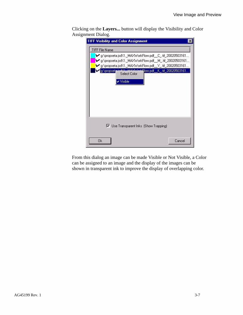
AG
View Image and Preview
Clicking on the Layers... button will display the Visibility and Color Assignment Dialog.
From this dialog an image can be made Visible or Not Visible, a Color can be assigned to an image and the display of the images can be shown in transparent ink to improve the display of overlapping color.
45199 Rev. 1 3-7

View Image and Preview
Click the mouse on the Use Transparent Inks checkbox to improve the visibility of overlapping inks.
3-8 AG45199 Rev. 1

AG
View Image and Preview
Right click the mouse on an image name and uncheck the Visible selection to hide that image.
45199 Rev. 1 3-9
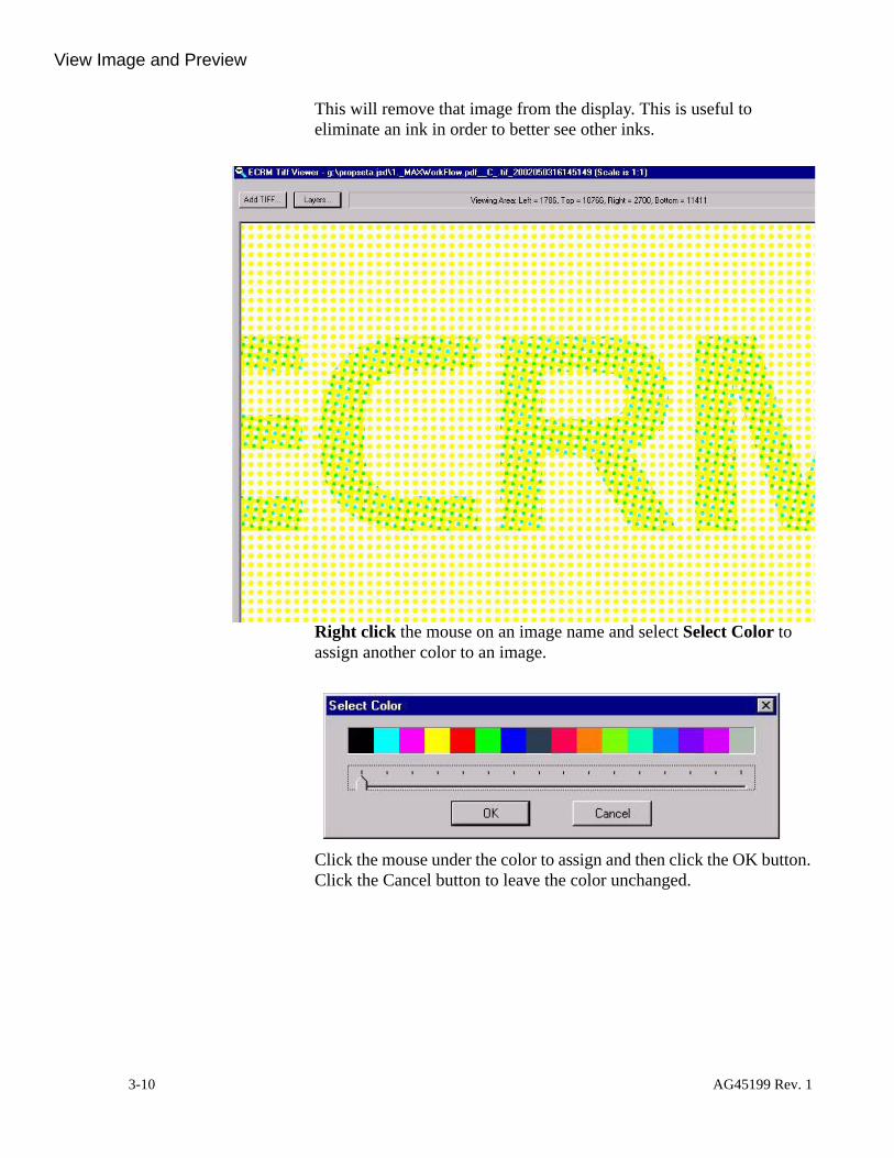
View Image and Preview
This will remove that image from the display. This is useful to eliminate an ink in order to better see other inks.
Right click the mouse on an image name and select Select Color to assign another color to an image.
Click the mouse under the color to assign and then click the OK button. Click the Cancel button to leave the color unchanged.
3-10 AG45199 Rev. 1
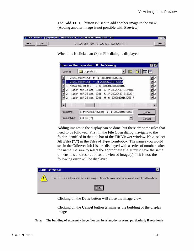
AG
View Image and Preview
The Add TIFF... button is used to add another image to the view. (Adding another image is not possible with Preview).
When this is clicked an Open File dialog is displayed.
Adding images to the display can be done, but there are some rules that need to be followed. First, in the File Open dialog, navigate to the folder identified in the title bar of the Tiff Viewer window. Next, select All Files (*.*) in the Files of Type Combobox. The names you would see in the CtServer Job List are displayed with a series of numbers after the name. Be sure to select the appropriate file. It must have the same dimensions and resolution as the viewed image(s). If it is not, the following error will be displayed.
Clicking on the Done button will close the image view.
Clicking on the Cancel button terminates the building of the display image
Note: The building of extremely large files can be a lengthy process, particularly if rotation is
45199 Rev. 1 3-11

AG
View Image and Preview
involved.
45199 Rev. 1 3-12

AG
Configure Tiff Viewer...
Configure Tiff Viewer...
This command enables the assignment of viewer colors to specific color names. Tiff files created by either the ECRM Tiff plug-in for the ECRM RIP or MaxWorkFlow ECRM Tiff contain special Tiff file tags to identify the color of the separation. The user can assign the names of the separations to one of 16 viewer colors by selecting File>Configure Tiff Viewer...
A dialog is presented that enables the assignment of separation names to specific colors.
45199 Rev. 1 3-13

AG
Configure Tiff Viewer...
The Set Automatic Color Selection Technology to use MaxWorkFlow Color Tag Convention checkbox will set the viewer to use the information set by the ECRM Tiff output from MaxWorkFlow when it is checked. The MaxWorkFlow convention specifies either Cyan, Magenta, Yellow or Black. It does not handle spot colors. When checked, images from MaxWorkFlow will display in the correct C,M,Y or K color.
Note: When this checkbox is checked, images from other sources may display in the incorrect color. Typically they will be displayed in Magenta.
The Color Name Tag Assignments enable the assignment of a color to a specific separation name when the ECRM Tiff plug-in for the ECRM RIP is used to generate the separations. The ECRM Tiff plug-in inserts a special ECRM Tiff Tag that identifies the separation name. This name is the name assigned in the creating application (for example Quark). In english, ‘cyan’, ‘magenta’, ‘yellow’ and ‘black’ are typically used for those colors. Additionally, a separation named ‘Spot Color 234’ may have been created. If this spot color is red, changing the string from ‘Red’ to ‘Spot Color 234’ will map that separation to red in the viewer. 16 distinct colors are available for mapping. If a separation comes in with a name that has not been mapped to a color, it will be assigned the next available color (not including cyan, magenta, yellow or black).
45199 Rev. 1 3-14

4Installing the Macintosh Services Software on Windows NT
This installation is not necessary if there are no Macintosh computers on the network. The following procedure can be initiated at any time prior to establishing a network link between a Macintosh workstation and the RIP server.
Note: Windows NT Server is required to install Macintosh Services. You cannot install these services on Windows NT Workstation.
Installation 1. Double-click on the Windows My Computer icon at the top left of the screen.
2. Double-click on the Control Panel icon.
AG45199 Rev. 1 4-1

Installation
3. Double-click on the Services icon.
4. Scroll through the Service’s list for File Server for Macintosh.
• If this service is present and started, no further action is required. Click on the Close button.
• If this service is missing (as shown above) click on the Close button and go on to step 5.
4-2 AG45199 Rev. 1

AG
Installation
5. Return to the Control Panel menu.
6. Double-click on the Network icon.7. Select the Services tab on the Network menu.
8. Click on the Add button.9. When the Select Network Services menu appears, use the scroll bar to
45199 Rev. 1 4-3

Installation
locate Services for Macintosh.
10. Highlight Services for Macintosh then click on the OK button. 11. Insert the Windows NT CD-ROM in the CD-ROM drive. The CD-
ROM automatically calls up the Windows NT Install screen. When the Windows NT logo appears, click on the X box in the upper right hand corner to close it.
12. When the Windows NT Setup dialog appears, click on the Continue button.
13. The program finds and installs the files from the CD-ROM and
4-4 AG45199 Rev. 1
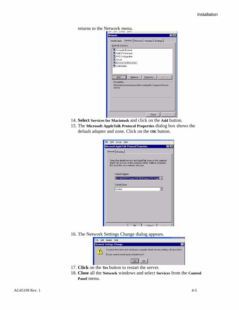
AG
Installation
returns to the Network menu.
14. Select Services for Macintosh and click on the Add button.15. The Microsoft AppleTalk Protocol Properties dialog box shows the
default adapter and zone. Click on the OK button.
16. The Network Settings Change dialog appears.
17. Click on the Yes button to restart the server.18. Close all the Network windows and select Services from the Control
Panel menu.
45199 Rev. 1 4-5

Installation
19. The scroll list shows the File Server for Macintosh (illustrated below).
20. Verify that both indicate Started in their Status column. If one is not started, (e.g. File Server for Macintosh) select it and click on the Start button.
21. Close the Services window.Note: You must now re-install your service pack. If you do not, you may have software version
mis-matches which could result in system problems.
22. Insert your Service Pack CD (CtServer requires Service Pack 5 or higher).
23. Follow the instructions for installing the Service Pack.
4-6 AG45199 Rev. 1

AG
Publishing
Publishing The following steps will be performed automatically during install and property set definition if these services were already installed, otherwise you will need to perform the following steps:
1. Click Start>Programs>Admin Tools>File Manager.• The screen displays a list of folders.
2. Select the desired folder from the list.3. Click on MacFile menu item, and click on create volume.
45199 Rev. 1 4-7

Publishing
• The screen displays a dialog box.
4. Click OK.
4-8 AG45199 Rev. 1

5File Naming Conventions
About File Name ParsingCtServer can perform file name parsing, which means the program can interpret encoded information that is imbedded in a file name.
In order to parse a file name, CtServer must know the naming conventions and parsing rules that you, the user, have established for your file names.
This appendix presents a model file naming convention and set of parsing rules to help you understand how file naming convention and parsing rules work.
By studying the model, you can learn how to develop file naming convention(s) and set of parsing rules of your own, and how to convey your conventions and rules to CtServer so that it can parse and operate on information you encode in your file names.
Note: The CtServer V 5.3 program this manual supports is the first version of CtServer to sup-port a file name parsing capability. Future versions of CtServer will utilize this new capability to increasingly greater extents, eventually using it to control job imaging. However, the current V 5.3 makes limited use of the capability; it just decodes the file name separation color information field to identify and properly display the separation color of the job when the View function is invoked.
The file name convention model we present incorporates 7 information fields in the file name. You file name convention can incorporate fewer or more fields in the file name.
The parsing rules for our file name convention are designed to demonstrate a wide range of parsing control features.
Example File Name Here’s an example of a file name that reflects the model file name convention and parsing rules we are about to present.
ECNCOLU_200310101E08K01.TIF
AG45199 Rev. 1 5-1
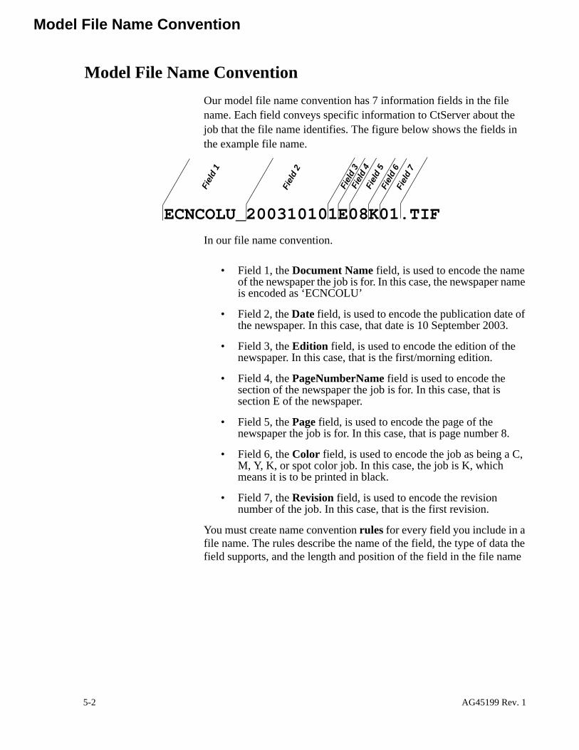
Model File Name Convention
Model File Name ConventionOur model file name convention has 7 information fields in the file name. Each field conveys specific information to CtServer about the job that the file name identifies. The figure below shows the fields in the example file name.
In our file name convention.
• Field 1, the Document Name field, is used to encode the name of the newspaper the job is for. In this case, the newspaper name is encoded as ‘ECNCOLU’
• Field 2, the Date field, is used to encode the publication date of the newspaper. In this case, that date is 10 September 2003.
• Field 3, the Edition field, is used to encode the edition of the newspaper. In this case, that is the first/morning edition.
• Field 4, the PageNumberName field is used to encode the section of the newspaper the job is for. In this case, that is section E of the newspaper.
• Field 5, the Page field, is used to encode the page of the newspaper the job is for. In this case, that is page number 8.
• Field 6, the Color field, is used to encode the job as being a C, M, Y, K, or spot color job. In this case, the job is K, which means it is to be printed in black.
• Field 7, the Revision field, is used to encode the revision number of the job. In this case, that is the first revision.
You must create name convention rules for every field you include in a file name. The rules describe the name of the field, the type of data the field supports, and the length and position of the field in the file name
ECNCOLU_200310101E08K01.TIFFi
eld
1
Fiel
d 2
Fiel
d 3
Fiel
d 4
Fiel
d 7
Fiel
d 6
Fiel
d 5
5-2 AG45199 Rev. 1

Model File Name Convention Field 1, Paper/Publication Name
string. The figure below lists the name convention rules for the 7 fields described above.
To create our set of name convention rules, we had to construct a set of rules for each of our information fields. The next few pages present the name convention rules we created for those fields. Study the material for a few minutes to get a basic understanding of what a rule definition is and what you must do to construct one.
Later, when you begin constructing your own rules, you may want to use this material as a guide for constructing your rules.
Field 1, Paper/
Publication Name
This arbitrary string represents the name of the publication. It may be variable in length. It starts with the first character of the filename and goes until an ‘_’.
See description of each item later in this document…
AG45199 Rev. 1 5-3

Model File Name Convention
Field 2,Date
This field is the date. It is numeric. It starts at the end of the prior field + 1 (remember the ‘_’) and it is 8 characters long.
5-4 AG45199 Rev. 1
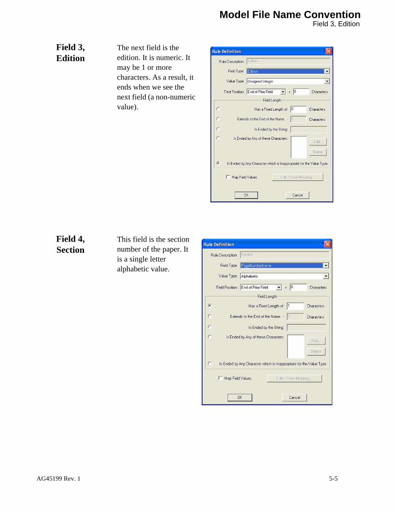
Model File Name Convention Field 3, Edition
Field 3,Edition
The next field is the edition. It is numeric. It may be 1 or more characters. As a result, it ends when we see the next field (a non-numeric value).
Field 4,Section
This field is the section number of the paper. It is a single letter alphabetic value.
AG45199 Rev. 1 5-5
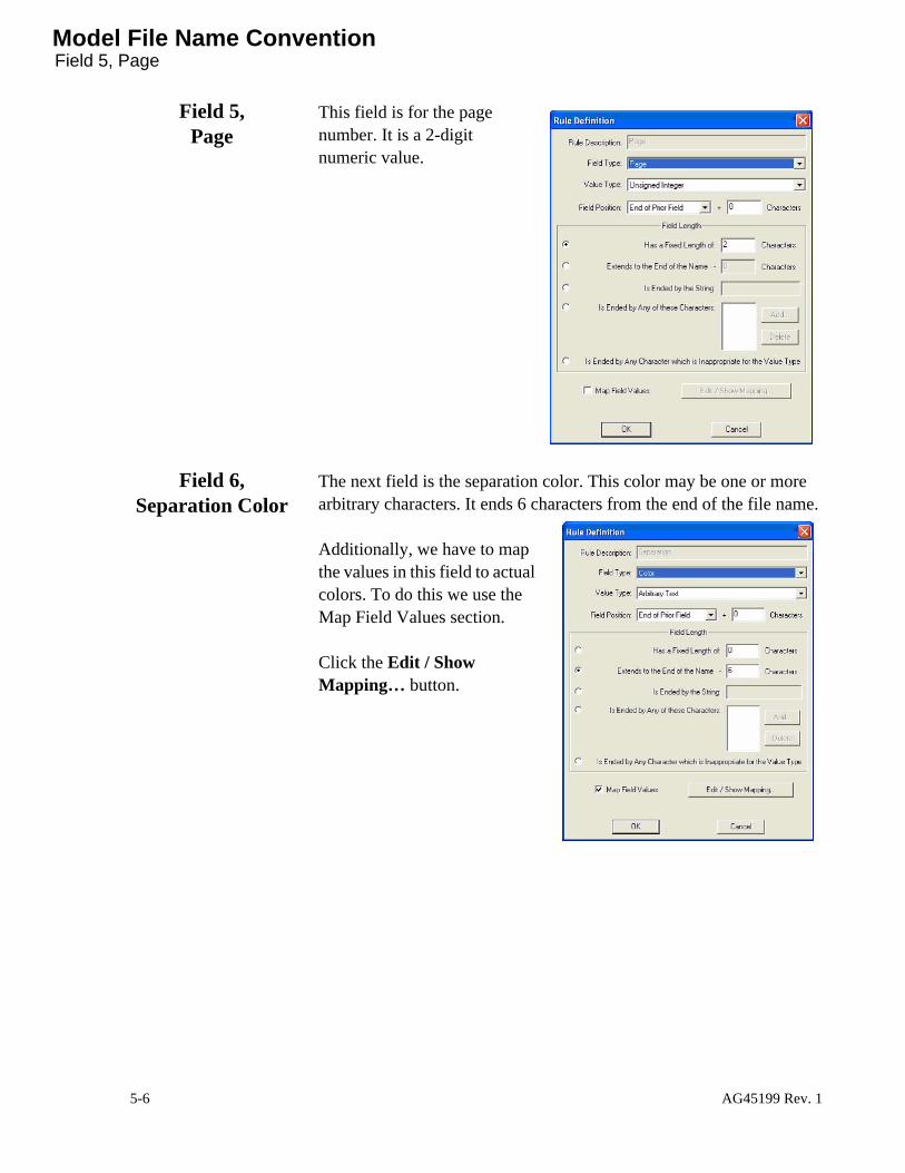
Model File Name ConventionField 5, Page
Field 5,Page
This field is for the page number. It is a 2-digit numeric value.
Field 6,Separation Color
The next field is the separation color. This color may be one or more arbitrary characters. It ends 6 characters from the end of the file name.
Additionally, we have to map the values in this field to actual colors. To do this we use the Map Field Values section.
Click the Edit / Show Mapping… button.
5-6 AG45199 Rev. 1

Model File Name Convention Field 7, Revision
The window shown at the right appears:
Add... will add an entry.
Delete... deletes an entry/
Field 7, Revision
After the separation color field is the revision field. This is a 2-digit numeric value that ends with the ‘.TIF’ string.
AG45199 Rev. 1 5-7

Working with Name Convention RulesCreating a New Set of Rules
Working with Name Convention Rules
Creating a New Set of Rules
To create a Set of Name Convention Rules for a file name field, refer to the figure below and proceed as follows:
1. From the CtServer File pull-down menu, select Set Naming Con-ventions...• The Configure Naming Conventions window opens.
2. Click the Name Convention Rules tab.3. Click the New... button.
• The Rule Definition window opens.
4. Fill in the dialog boxes as required to complete the rule definition. See “Creating a new Rule Set” on page 115.
5. Click the OK button to save the rule definition• The Configure Naming Conventions window opens and your
new definition is listed
6. Repeat steps 3 through 5 as needed to establish rule definitions for all of your information fields.
1
2
5
4
3
5-8 AG45199 Rev. 1

Defining a Rule Set Modifying or Deleting an Existing Set of Rules
Modifying or Deleting an
Existing Set of Rules
You can modify or delete any rule definition you create. To do either:
1. Navigate to the Configure Naming Conventions window.2. Click on the Name Convention Rules tab.3. Select (highlight) the rule you want to edit or delete.4. To edit the rule, click on the Edit... button. The Rule Definition
window for the rule opens. Edit the rule definition as needed, and then click OK when you are finished.
5. To delete the rule, click the Delete button. The rule will be deleted and be cleared from the Name Convention Rules window.
6. When you are finished working with the name convention rules, click the Close button to close the Name Convention Rules win-dow.
Defining a Rule Set1. From the CtServer File pull-down menu, select Set Naming Con-
ventions...• The Configure Naming Conventions window opens.
2. Click the Name Convention Rules tab.3. Click the New... button.
• The Rule Definition window opens
12
3
54
6
AG45199 Rev. 1 5-9

Defining a Rule SetModifying or Deleting an Existing Set of Rules
4. In the Rule Description box, type a descriptive name of the rule to defined .
5. In the Field Type box, make as selec-tion from the list. This assigns a field type.
6. In the Value Type box, make a selection from the list. This defines the interpretation of the characters in the field. It also identifies the legal characters for the field.
5
4
6
5-10 AG45199 Rev. 1

Defining a Rule Set Modifying or Deleting an Existing Set of Rules
7. In the Field Posi-tion box, select from the list. This defines where the field starts in the file name. Additionally, the number of charac-ters to add (Start of Name or End of Prior Field) or sub-tract (for End of Name) can be speci-fied.
8. If ‘After String’ is selected, enter the name of the string.
9. Click the Has a fixed length of x Charac-ters button if the field is to always the same length. Then, enter the length in characters.
10. Click the Extends to the End of the Name – x Characters but-ton if the end of the field can be specified relative to the end of the file name. Then, enter the number of characters.
11. Click the Is ended by the string xxx button if the field is always followed by a specific character sequence. Then, enter the character sequence.
12. Click the Is ended by any of these characters button if the field is to be ended by a single character (or any of a number of single characters).
7
8
10
9
1112
AG45199 Rev. 1 5-11
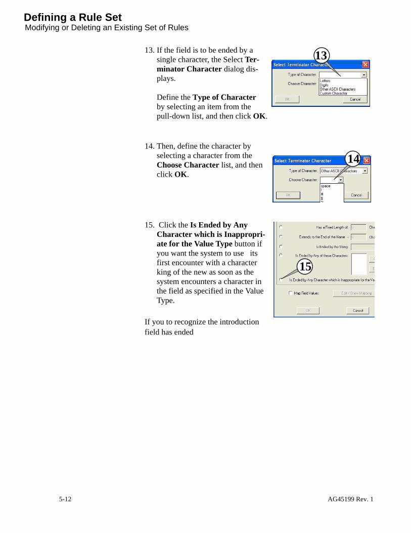
Defining a Rule SetModifying or Deleting an Existing Set of Rules
13. If the field is to be ended by a single character, the Select Ter-minator Character dialog dis-plays. Define the Type of Character by selecting an item from the pull-down list, and then click OK.
14. Then, define the character by selecting a character from the Choose Character list, and then click OK.
15. Click the Is Ended by Any Character which is Inappropri-ate for the Value Type button if you want the system to use its first encounter with a character king of the new as soon as the system encounters a character in the field as specified in the Value Type.
If you to recognize the introduction field has ended
13
14
15
5-12 AG45199 Rev. 1

Defining a Rule Set Modifying or Deleting an Existing Set of Rules
If Map field is checked, the Edit/Show mapping button is enabled.The following dialog will appear.
Clicking the ‘Add…’ button will display the following dialog. Enter the field value and the string/value to map it to.
AG45199 Rev. 1 5-13

Naming Convention SetModifying or Deleting an Existing Set of Rules
Naming Convention SetAfter you define the rules, you must create the naming convention set. The naming convention set defines which fields will make up the file name, and in what order.
To create a naming convention set:
1. Navigate to the Configure Naming Conventions window.2. Click on the Name Convention Sets tab.3. Enter a name for the new naming convention set in the Set Name:
dialog box shown below. 4. Construct the naming convention set. For every field you want to
include, move the rules for that field from the “Unused Rules” list on the left to the “Rules Used in Set “list on the right.
5. Use the Move Up and Move Down keys to order the rules as set the fields in the proper order
Note: The rules must be in order. This is because some rules start at the end of the prior rule.
Selecting the Use Rules radio button shows the above fields.
Use Standard Naming Convention radio button will use the standard Harlequin RIP default naming conventions. This will work for C, M, Y, K jobs but it will not work correctly for spot color jobs.
5-14 AG45199 Rev. 1

Naming Convention Set Testing The Naming Convention Set
Use ECRM Private Tag Encoding radio button will use the ECRM TIFF Tags inserted by the ECRM TIFF plug-in (or other ECRM aware TIFF generation program).
Add to Set is used to move the selected rule from the Unused Ruled list to the Rules Used in Set list.
Remove from Set is used to move the selected rule from the Rules Used in Set list to the Unused Ruled list.
Move UP will move a rule up in the Rules Used in Set list. Order is important.
Move Down will move a rule down in the Rules Used in Set list. Order is important.
Testing The Naming
Convention Set
Once the naming conventions defined, it can be tested with actual file names. If the rules work properly, each field value is displayed in the dialog. Otherwise, the rule that had an error will be displayed.
AG45199 Rev. 1 5-15
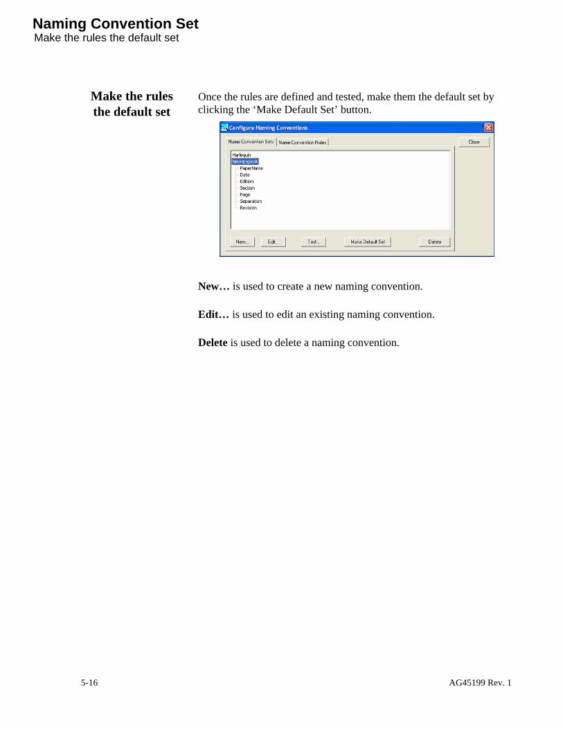
Naming Convention SetMake the rules the default set
Make the rules the default set
Once the rules are defined and tested, make them the default set by clicking the ‘Make Default Set’ button.
New… is used to create a new naming convention.
Edit… is used to edit an existing naming convention.
Delete is used to delete a naming convention.
5-16 AG45199 Rev. 1