Embed Size (px)
Citation preview
8.930-370.0-AD 03/08/17
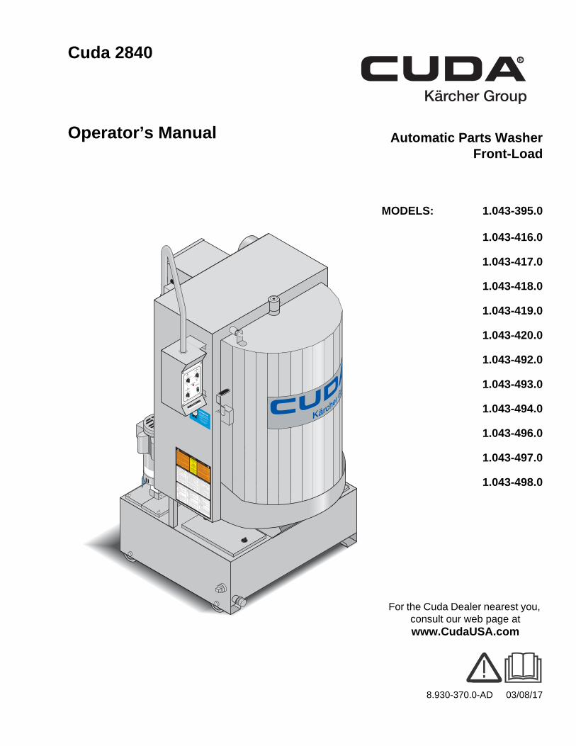
Cuda 2840
Operator’s Manual Automatic Parts WasherFront-Load
ATTENTION
USE ONLY CUDA APPROVED
DETERGENTS TO EXTEND
LABOR WARRANTY TO 1-YEAR!
MIX DETERGENTS 1 LB (1/2 KG) PER
5-GALLONS (15 LITERS) OF WATER
For CUDA Approved Detergents visit
http://www.cudausa.com or
call 888-319-0882
9.807-513.0
90-DAY LABOR WARRANTY
EXTENDS TO 1-YEAR
WITH EXCLUSIVE USE OF
CUDA DETERGENTS
LIMITED
This is a heated parts cleaner. Use only nonflammable, non-
combustible, water-based cleaning compounds in this machine.
Do not fill or contaminate with any flammable or combustible
material such as gasoline, alcohol, mineral spirits, etc. Drain parts
to be cleaned of any combustible or flammable material before
placing inside cabinet. Failure to observe this warning will create
an extremely hazardous condition.
Este es un limpiador de partes que se calienta. Utilice sola-
mente en esta máquina componentes de limpieza base agua, no
inflamables y no combustibles. No llenar o contaminar con algún
material inflamable como, gasolina, alcohol, esencias minerales,
etc. Drene las partes a ser limpiadas de cualquier combustible o
material inflamable antes de introducir en el gabinete. Si
descuida observar estas precauciones, pueden crearse condicio-
nes extremadamente peligrosas.
Ce nettoyeur de pièces est chauffé. Utiliser dans cet appareil
seulement des nettoyeurs à base d’eau, non combustibles et non
inflammables. Ne pas y ajouter ou contaminer avec des matériaux
combustibles tels: gasoline, alcool, etc. Vider les pièces contenant
des matériaux combustibles ou inflammables avant de les placer
à l’intérieur du cabinet. Ne pas observer ces avertissements peut
créer des situations risquées.
HOT WATER
Before opening lid, wait 5
seconds to allow spray
arm/turntable to stop
spinning.AGUA
CALIENTE
Antes de abrir la tapa,
espere 5 segundos para
que la barra rotatoria se
detenga.EAU CHAUDE
Avant d’ouvrir le couvert,
attendez 5 secondes pour
permettre au bras vaporisa-
teur/plaque tournante d’arrêter
de tourner.
WARNING
PRECAUCION / ADVERTISSEMENT
CAUTION
CUIDADO / ATTENTION
OPERATING INSTRUCTIONS
INSTRUCCIONESDE OPERACION
INSTRUCTIONS D’OPÉRATION
IMPORTANT: Before operating this machine,
completely familiarize yourself with instruction
manual provided. Only authorized and properly
instructed individuals should operate this machine.
Before loading parts onto turntable/ basket, be cer-
tain the pump is off and not running and the wash
solutions are at operating temperature.
1. Fill tank with water and cleaning solution.
Water level should be 2" below the access doors.
Check daily.
2. Program heater timer for desired period of
operation. Allow time for unit to preheat cleaning
solution.3. Open door/lid and place articles to be clean onto
basket/turntable. Be certain no parts protrude
through the bottom or beyond the sides of the
basket/turntable. Do not exceed the specified
height or weight limit for this spray wash cabinet.
4. Close door/lid and latch securely. With machine
set to wash, turn “wash cycle” timer to the desired
cleaning time. Pump will start and run until time
has expired.
5. Before opening the door/lid, turn wash cycle timer
off and wait 5 seconds for machine to stop spin-
ning. This will allow steam to escape the cabinet
and excess water to drain from your parts.
IMPORTANTE: Antes de oparar el equipo, familiarícese com-
pletamente con el manual de operación que se incluye. Solo
personal autorizado y debidamente capacitado debe oparar
éste equipo. Antes de abrir la puerta/cubierta o las piezas de
carga sobre la tornamesa/canasta, asegúrese de que la bomba
esté apagada y sin funcionar, y que las soluciones de limpieza
estén a temperatura de funcionamiento.
1. Llene el depósito con agua y la solución para limpieza. El
nivel del agua debe estar 2" por debajo de las puerta de ac-
ceso. Verifique el nivel diariamente.
2. Programe el Temporizador del calentador para el período de
operación deseado. Deje pasar un tiempo para que la unidad
precaliente la solución para limpieza.
3. Abra la puerta/tapa y coloque las piezas a lavar en la tor-
namesa/canasta, asegúrese de que ninguna pieza so-
brepase el fondo ni el perímetro de la tornamesa. No exceda
los limites especificados de peso y altura para el gabinete de
lavado.4. Cierre la puerta/tapa y asegure el candado. Con la máquina
en posición de lavar, ajuste el temporizador de “ciclo de
lavado” al tiempo deseado. La bomba arrancará y funcionará
durante el tiempo seleccionado.
5. Antes de abrir la puerta/cubierta, apague el temporizador del
ciclo de lavado y espere 5 segundos para que la máquina
deje de girar. Esto permitirá que el vapor salga del gabinete y
el exceso de agua drene de las piezas.
IMPORTANT: Avant d’utiliser cette machine, familiarisez-
vous complètement avec le manuel d’instruction fourni. Cette
machine devrait être utilisée seulement par du personnel
autorisé et formé. Avant l’ouverture de la porte/du couvercle
ou du chargement des pièces sur la table tournante/le panier,
s’assurer que la pompe est en position arrêt et ne fonctionne
pas et que les solutions de lavage sont à température de
fonctionnement.
1. Remplir le réservoir d’eau et d’une solution de nettoyage.
Le niveau d’eau doit se trouver à 5 cm (2 po) sous les
portes d’accès. Vérifier quotidiennement.
2. Programmer le minuterie de chauffage de l’appareil pour
la période de fonctionnement souhaitée. Prévoir du temps
pour que l’appareil préchauffe la solution de nettoyage.
3. Ouvrir la porte/couvert et placez les articles à être lavé
sur le panier/plaque tournante. Assurez-vous qu’il n’y est
aucune pièce dépassant le painer ou dans le fond au-delà
du painer/plaque tournante.
4. Fermez la porte/couvert et verrouillez de façon sécuritaire.
La machine prête pour le lavage, tournez le minuteur “wash
cycle” au temps de la lavage désiré. La pompe fonctionnera
jusqu’à ce que temps sélectionné soit écoulé.
5. Avant d’ouvrir la porte/le couvercle, mettre la minuterie du
cycle de lavage à l’arrêt et attendre pendant 5 secondes que
l’appareil s’arrête de tourner. Cela permettra à la vapeur de
s’échapper du cabinet et à l’excès d’eau de s’écouler de vos
pièces.
WARNING
PRECAUCION / ADVERTISSEMENT
• Machine must be connected to a properly sized
lockable disconnect.
• Installation must comply with NEC code.
• For supply connection, use wires acceptable for
at least 90 degrees C.
• Do not use below grade floor or grade level.
The following schedule is based on average use.
Higher usage may require more frequent mainte-
nance.IMPORTANT: Be sure electrical supply is OFF be-
fore draining sump. Only qualified personnel should
service this machine.
DAILY: • Check water level in the sump daily. Topping
off the water daily will prevent damage to the
heater element.
• Remove and clean debris screen.
• Visually check for plugged nozzles. Remove
and clean if needed. Reinstall in the exact origi-
nal position.
WEEKLY: •
Grease/oil door hinges.
MONTHLY: •
Perform visual check of turntable drive chain.
• Drain wash solution from sump, remove sand/
grit from bottom of the sump. Care should be
taken to avoid bending or damaging heater ele-
ment during the cleaning process.
• When sump has been cleaned and refilled with
water, add the recommended quantity of deter-
gent for your machine.
NOTE: Dissolve cleaning powder into warm water
before adding the manufacturer’s recommended
amount to the tank.
8.922-402.0
• La máquina debe estar conectada a un enchufe
eléctrico de seguridad.
• La instalación debe cumplir con el código NEC.
• Para las conexiones de alimentación, use cablea-
do para al menos 90 grados centígrados.
No utilice por debajo del nivel del piso.
• L’appareil doit être connecté à un sectionneur
verrouillable de taille appropriée.
• L’installation doit se conformer au code NEC.
• Pour le raccordement de l’alimentation, utiliser des
fils pouvant accepter au moins 90 degrés Celsius.
Ne pas utiliser un calibre ou un grade inférieur.
Le tableau suivant est fondé sur une utilisation moyenne.
Une utilisation plus importante peut exiger un entretien plus
fréquent.IMPORTANT : S’assurer que le système électrique est à l’arrêt
avant de vider le réservoir. Seul le personnel qualifié doit ré-
parer cet appareil.
QUOTIDIENNEMENT:
• Vérifier quotidiennement le niveau d’eau dans le rés-
ervoir. Le remplissage quotidien d’eau permet d’éviter
d’endommager l’élément chauffant.
• Démonter et nettoyer le filtre à débris.
• Vérifier visuellement si des buses sont bouchées/ob-
struées. Démonter et nettoyer, le cas échéant. Réinstaller
dans la position initiale exacte.
HEBDOMADAIREMENT:
• Graisser/huiler les pentures/charnières de la porte.
MENSUELLEMENT:
• Procéder à un contrôle visuel de la chaîne d’entraînement
de la table tournante.
• Assécher la solution de lavage du réservoir, et enlever tout
sable/gravier se trouvant au fond. Des précautions doivent
être prises pour éviter de plier/courber l’élément chauffant
ou de l’endommager au cours du processus de nettoyage.
• Lorsque le réservoir a été nettoyé et rempli d’eau, ajouter la
quantité de détergent recommandée pour votre appareil.
NOTE: Bien dissoudre la poudre dans l’eau chaude avant
d’ajouter dans le réservoir.
El plan de mantenimiento que se presenta a continuación, está
basado en un uso promedio del equipo. Un uso más frecuente o
severo puede requerir un mantenimiento más frecuente.
IMPORTANTE: Asegúrese de que el sistema eléctrico esté
APAGADO antes de vaciar el cárter. Sólo personal calificado
debe reparar esta máquina.
DIARIAMENTE:
• Compruebe el nivel del agua en el cárter diariamente.
Mantener el nivel adecuado del agua evitará dañar el
elemento del calentador.
• Retire y limpie los residuos de la criba.
• Compruebe visualmente que las boquillas están instaladas
correctamente. Retire y limpie si es necesario. Reinstale en
la posición original exacta.
SEMANALMENTE:
• Lubrique las bisagras de la puerta.
MENSUALMENTE:
• Realice una verificación visual de la cadena de propulsión
de la tornamesa.
• Drene la solución de limpieza del cárter, retire del fondo de
cárter los sedimentos. Debe tener cuidado de no doblar o
dañar el elemento del calentador durante el proceso de
limpieza.•
Una vez que el cárter está limpio y relleno de agua,
agregue la cantidad recomendada de detergente para la
máquina.NOTA: Disuelva el detergente en agua caliente antes de agregar-
lo al tanque en la cantidad recomendada por el fabricante.
MAINTENANCE INSTRUCTIONSINSTRUCCIONES DE MANTENIMIENTO
DIRECTIVES D’ENTRETIEN
MODELS: 1.043-395.0
1.043-416.0
1.043-417.0
1.043-418.0
1.043-419.0
1.043-420.0
1.043-492.0
1.043-493.0
1.043-494.0
1.043-496.0
1.043-497.0
1.043-498.0
For the Cuda Dealer nearest you, consult our web page at www.CudaUSA.com

2 Cuda 2840 8.930-370.0 - AD
Machine Data Label

3
Table of Contents
Machine Data Label . . . . . . . . . . . . . . . . . . . . . . . . . .2
Table of Contents . . . . . . . . . . . . . . . . . . . . . . . . . . .3
How To Use This Manual . . . . . . . . . . . . . . . . . . . . .4
SafetyIntroduction & Safety Information . . . . . . . . . . . . . . .5General Safety Information . . . . . . . . . . . . . . . . . . . .6
OperationsComponent Identification - Front View . . . . . . . . . . .8Component Identification - Rear View . . . . . . . . . . .9Component Identification - Front - Options . . . . . . .10
Installation . . . . . . . . . . . . . . . . . . . . . . . . . . . . . . . .11Before You Begin . . . . . . . . . . . . . . . . . . . . . . . . . .11Step 1: Make Electrical Connections . . . . . . . . . . .11Step 2: Configure The 24-hour, 7-day Timers . . . .11Step 3: Connect A Compressed-
Air Line And Accessories . . . . . . . . . . . . . . . . . .11Step 4: Connect A Water Line . . . . . . . . . . . . . . . .12Step 5: Fill The Machine With Water And Add
Detergent . . . . . . . . . . . . . . . . . . . . . . . . . . . . . .12
Operation . . . . . . . . . . . . . . . . . . . . . . . . . . . . . . . . .14Main Operating Components . . . . . . . . . . . . . . . . .14Control Panel . . . . . . . . . . . . . . . . . . . . . . . . . . . . .14Heater Control. . . . . . . . . . . . . . . . . . . . . . . . . . . . .14Wash Cycle Control . . . . . . . . . . . . . . . . . . . . . . . .14Turntable Switch . . . . . . . . . . . . . . . . . . . . . . . . . . .14Low Water Indicator . . . . . . . . . . . . . . . . . . . . . . . .1424-hour, 7-day Timers. . . . . . . . . . . . . . . . . . . . . . .14Thermostat . . . . . . . . . . . . . . . . . . . . . . . . . . . . . . .14Door Safety Switch . . . . . . . . . . . . . . . . . . . . . . . . .15Adjusting the Safety Switch . . . . . . . . . . . . . . . . . .15Debris Screen . . . . . . . . . . . . . . . . . . . . . . . . . . . . .15Air Flow Valve (Optional) . . . . . . . . . . . . . . . . . . . .15Detail Sump . . . . . . . . . . . . . . . . . . . . . . . . . . . . . .16Power Brush (Optional). . . . . . . . . . . . . . . . . . . . . .16Detail Brush and Flow Regulator . . . . . . . . . . . . . .16Adjusting the Flow of Cleaning Solution . . . . . . . . .16Oil Skimmer . . . . . . . . . . . . . . . . . . . . . . . . . . . . . .17Water Level. . . . . . . . . . . . . . . . . . . . . . . . . . . . . . .17Automatic Water Fill (Optional) . . . . . . . . . . . . . . . .17Low Water Shut-off . . . . . . . . . . . . . . . . . . . . . . . . .17Filtration System (Optional) . . . . . . . . . . . . . . . . . .18Sump Sweep System (Optional). . . . . . . . . . . . . . .18Detergents And Additives . . . . . . . . . . . . . . . . . . . .18Preparing The Machine For Use. . . . . . . . . . . . . . .19Washing Parts. . . . . . . . . . . . . . . . . . . . . . . . . . . . .19Shutting Down The Machine. . . . . . . . . . . . . . . . . .19
MaintenanceMaintaining The Machine . . . . . . . . . . . . . . . . . . . .20
Daily Maintenance . . . . . . . . . . . . . . . . . . . . . . . . .20Weekly Maintenance. . . . . . . . . . . . . . . . . . . . . . . .20Monthly Maintenance . . . . . . . . . . . . . . . . . . . . . . .20Semi-Annual Maintenance . . . . . . . . . . . . . . . . . . .20Cleaning and Aligning the Spray Nozzles. . . . . . . .21Cleaning the Filters . . . . . . . . . . . . . . . . . . . . . . . . .23
Repairing The Machine . . . . . . . . . . . . . . . . . . . . . .24Heating Elements . . . . . . . . . . . . . . . . . . . . . . . . . .24Thermostat . . . . . . . . . . . . . . . . . . . . . . . . . . . . . . .24Turntable Motor. . . . . . . . . . . . . . . . . . . . . . . . . . . .25Timers and Switches on the Control Panel . . . . . . .26Oil Skimmer Motor . . . . . . . . . . . . . . . . . . . . . . . . .26Required Tools and Equipment . . . . . . . . . . . . . . .26
Troubleshooting . . . . . . . . . . . . . . . . . . . . . . . . . . .28Troubleshooting The Electrical System . . . . . . . . .28Troubleshooting a Single Phase Panel . . . . . . . . . .28Troubleshooting a Three Phase Panel . . . . . . . . . .29Testing Individual Components. . . . . . . . . . . . . . . .30
PartsCuda 2840 Front . . . . . . . . . . . . . . . . . . . . . . . . . . 36Cuda 2840 Rear . . . . . . . . . . . . . . . . . . . . . . . . . . 40Spray Arm . . . . . . . . . . . . . . . . . . . . . . . . . . . . . . . 44TT Motor . . . . . . . . . . . . . . . . . . . . . . . . . . . . . . . . 46Side Control Panel . . . . . . . . . . . . . . . . . . . . . . . . 48Electrical Panel - 208V 1PH . . . . . . . . . . . . . . . . . 50Electrical Panel - 230V 1PH . . . . . . . . . . . . . . . . . 52Electrical Panel - 208V 3PH . . . . . . . . . . . . . . . . . 54Electrical Panel - 230V 3PH . . . . . . . . . . . . . . . . . 56Electrical Panel - 460V 3PH . . . . . . . . . . . . . . . . . 58Electrical Panel - 575V 3PH . . . . . . . . . . . . . . . . . 60Oil Skimmer . . . . . . . . . . . . . . . . . . . . . . . . . . . . . 62Door Latch . . . . . . . . . . . . . . . . . . . . . . . . . . . . . . 64
Cuda 2840 8.930-370.0 - AD

4
How To Use This Manual
This manual contains the following sections:
• How to Use This Manual
• Safety
• Operations
• Maintenance
• Parts List
The HOW TO USE THIS MANUAL section will tell you how to find important information for ordering correct repair parts.
Parts may be ordered from authorized dealers. When placing an order for parts, the machine model and machine serial number are important. Refer to the MACHINE DATA box which is filled out during the installation of your machine. The MACHINE DATA box is located on the inside of the front cover of this manual.
The model and serial number of your machine is located on the back of the machine.
The SAFETY section contains important information regarding hazardous or unsafe practices of the machine. Levels of hazards are identified that could result in product damage, personal injury, or severe injury resulting in death.
The OPERATIONS section is to familiarize the operator with the operation and function of the machine.
The MAINTENANCE section contains preventive main-tenance to keep the machine and its components in good working condition. They are listed in this general order:
• Maintaining The Machine• Daily Maintenance• Weekly Maintenance• Monthly Maintenance• Semi-Annual Maintenance• Cleaning and Aligning the Spray Nozzles• Cleaning the Filters• Repairing The Machine• Heating Elements• Thermostat• Turntable Motor• Timers and Switches on the Control Panel• Oil Skimmer Motor• Required Tools and Equipment• Troubleshooting• Troubleshooting The Electrical System• Troubleshooting a Single Phase Panel• Troubleshooting a Three Phase Panel• Testing Individual Components
The PARTS LIST section contains assembled parts illustrations and corresponding parts list. The parts lists include a number of columns of information:
• REF – column refers to the reference number on the parts illustration.
• PART NO. – column lists the part number for the part.
• QTY – column lists the quantity of the part used in that area of the machine.
• DESCRIPTION – column is a brief description of the part.
• NOTES – column for information not noted by the other columns.
NOTE: If a service or option kit is installed on your machine, be sure to keep the KIT INSTRUCTIONS which came with the kit. It contains replacement parts numbers needed for ordering future parts.
NOTE: The manual part number is located on the lower right corner of the front cover.
Model:
Date of Purchase:
Serial Number:
Dealer:
Address:
Phone Number:
Sales Representative:
Cuda 2840 8.930-370.0 - AD
5
Safety
Introduction & Safety Information
This manual covers the operation and maintenance of your automatic parts washer. All information in this manual is based on the latest product information available at the time of printing.
We reserve the right to make changes at any time without incurring any obligation.
Owner/User Responsibility:
The owner and/or user must have an understanding of the manufacturer’s operating instructions and warnings before using this machine. Warning information should be emphasized and understood. If the operator is not fluent in English, the manufacturer’s instructions and warnings shall be read to and discussed with the operator in the operator’s native language by the purchaser/owner, making sure that the operator comprehends its contents.
Owner and/or user must study and maintain for future reference the manufacturers’ instructions.
Save these Instructions
This manual should be considered a permanent part of the machine and should remain with it if machine is resold.
When ordering parts, please specify model and serial number. Use only identical replacement parts.
This machine is to be used only by trained operators.
Cuda 2840 8.930-370.0 - AB
6
Safety
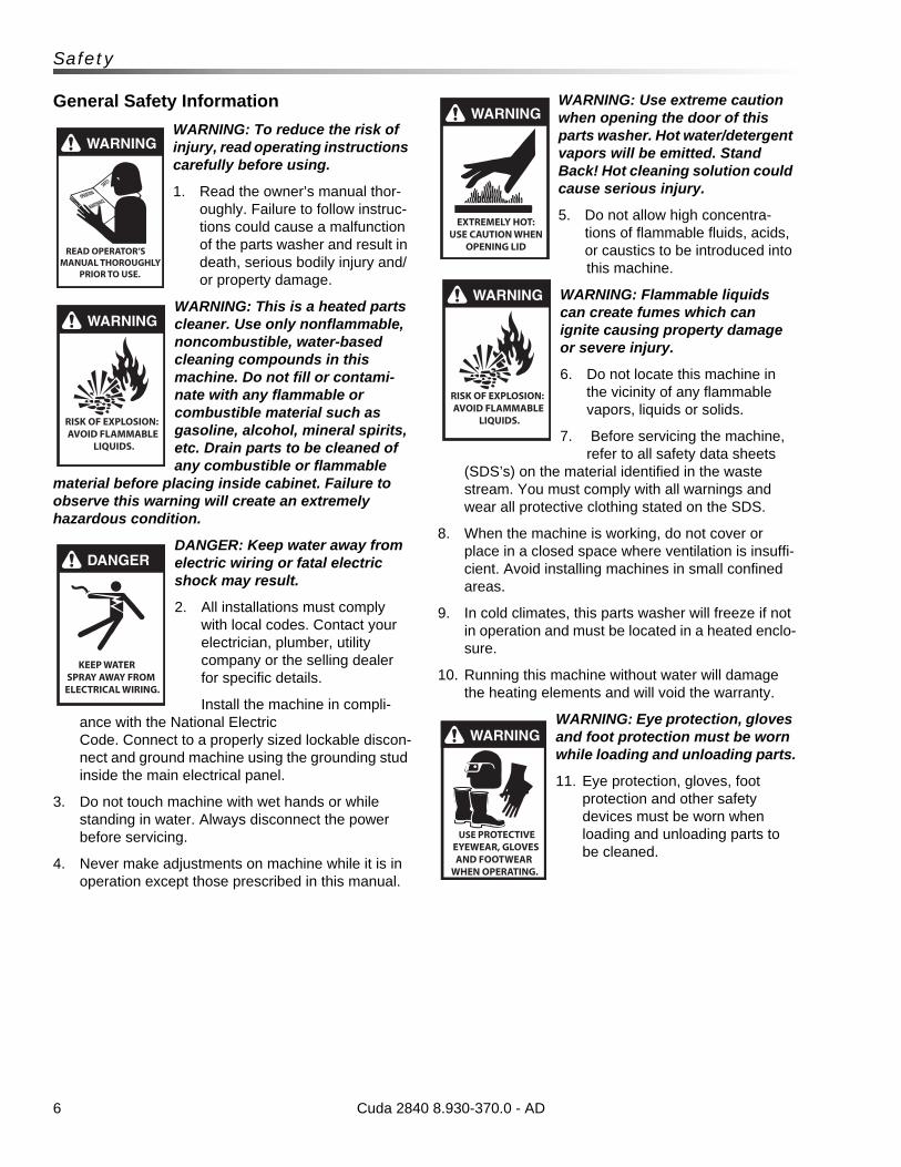
General Safety Information
WARNING: To reduce the risk of injury, read operating instructions carefully before using.
1. Read the owner’s manual thor-oughly. Failure to follow instruc-tions could cause a malfunction of the parts washer and result in death, serious bodily injury and/or property damage.
WARNING: This is a heated parts cleaner. Use only nonflammable, noncombustible, water-based cleaning compounds in this machine. Do not fill or contami-nate with any flammable or combustible material such as gasoline, alcohol, mineral spirits, etc. Drain parts to be cleaned of any combustible or flammable
material before placing inside cabinet. Failure to observe this warning will create an extremely hazardous condition.
DANGER: Keep water away from electric wiring or fatal electric shock may result.
2. All installations must comply with local codes. Contact your electrician, plumber, utility company or the selling dealer for specific details.
Install the machine in compli-ance with the National ElectricCode. Connect to a properly sized lockable discon-nect and ground machine using the grounding stud inside the main electrical panel.
3. Do not touch machine with wet hands or while standing in water. Always disconnect the power before servicing.
4. Never make adjustments on machine while it is in operation except those prescribed in this manual.
WARNING: Use extreme caution when opening the door of this parts washer. Hot water/detergent vapors will be emitted. Stand Back! Hot cleaning solution could cause serious injury.
5. Do not allow high concentra-tions of flammable fluids, acids, or caustics to be introduced into this machine.
WARNING: Flammable liquids can create fumes which can ignite causing property damage or severe injury.
6. Do not locate this machine in the vicinity of any flammable vapors, liquids or solids.
7. Before servicing the machine, refer to all safety data sheets
(SDS’s) on the material identified in the waste stream. You must comply with all warnings and wear all protective clothing stated on the SDS.
8. When the machine is working, do not cover or place in a closed space where ventilation is insuffi-cient. Avoid installing machines in small confined areas.
9. In cold climates, this parts washer will freeze if not in operation and must be located in a heated enclo-sure.
10. Running this machine without water will damage the heating elements and will void the warranty.
WARNING: Eye protection, gloves and foot protection must be worn while loading and unloading parts.
11. Eye protection, gloves, foot protection and other safety devices must be worn when loading and unloading parts to be cleaned.
Cuda 2840 8.930-370.0 - AD
WARNING
READ OPERATOR’S MANUAL THOROUGHLY PRIOR TO USE.
OPERATIONSSAFETY
MAINTENANCE
WARNING
RISK OF EXPLOSION: AVOID FLAMMABLE
LIQUIDS.
DANGER
KEEP WATER SPRAY AWAY FROM ELECTRICAL WIRING.
WARNING
RISK OF EXPLOSION: AVOID FLAMMABLE
LIQUIDS.
WARNING
EXTREMELY HOT:USE CAUTION WHEN
OPENING LID
WARNING
USE PROTECTIVE EYEWEAR, GLOVES
AND FOOTWEAR WHEN OPERATING.
7
Safety
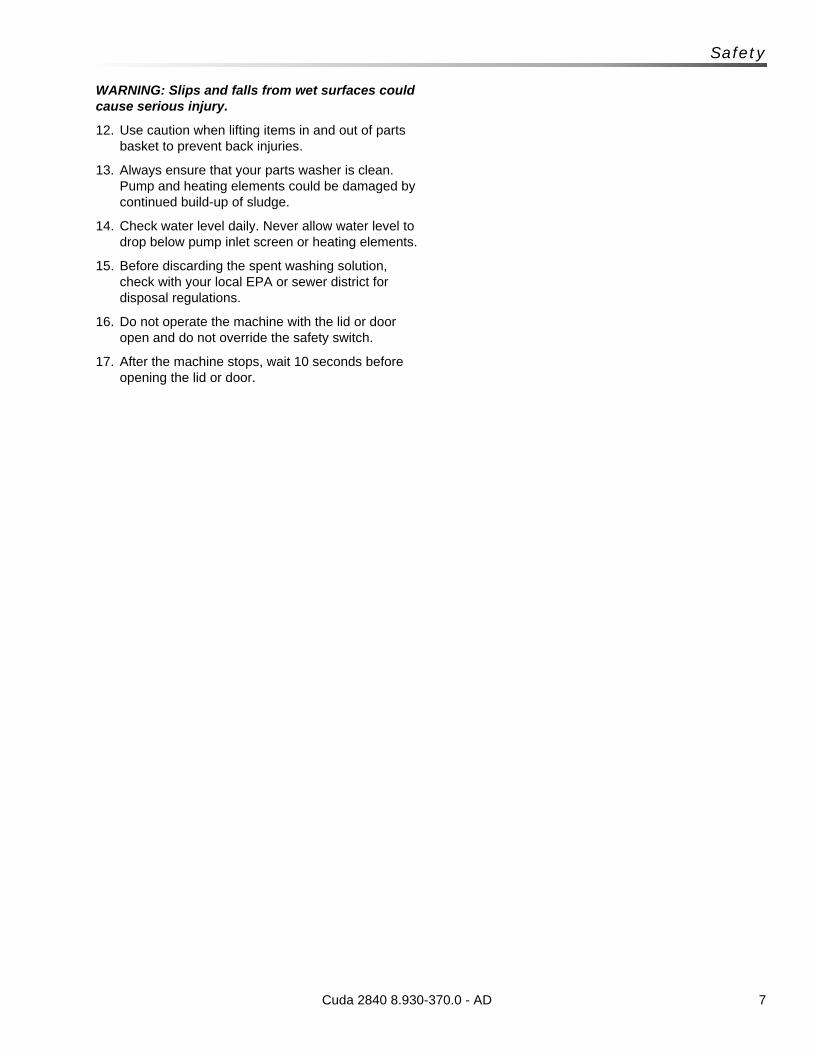
WARNING: Slips and falls from wet surfaces could cause serious injury.
12. Use caution when lifting items in and out of parts basket to prevent back injuries.
13. Always ensure that your parts washer is clean. Pump and heating elements could be damaged by continued build-up of sludge.
14. Check water level daily. Never allow water level to drop below pump inlet screen or heating elements.
15. Before discarding the spent washing solution, check with your local EPA or sewer district for disposal regulations.
16. Do not operate the machine with the lid or door open and do not override the safety switch.
17. After the machine stops, wait 10 seconds before opening the lid or door.
Cuda 2840 8.930-370.0 - AD
8
Operations
Component Identification - Front View
Cuda 2840 8.930-370.0 - AD
ATTENTION
USE ONLY CUDA APPROVED
DETERGENTS TO EXTEND
LABOR WARRANTY TO 1-YEAR!
MIX DETERGENTS 1 LB (1/2 KG) PER
5-GALLONS (15 LITERS) OF WATER
For CUDA Approved Detergents visit
http://www.cudausa.com or
call 888-319-0882
9.807-513.0
90-DAY LABOR WARRANTY
EXTENDS TO 1-YEAR
WITH EXCLUSIVE USE OF
CUDA DETERGENTS
LIMITED
This is a heated parts cleaner. Use only nonflammable, non-
combustible, water-based cleaning compounds in this machine.
Do not fill or contaminate with any flammable or combustible
material such as gasoline, alcohol, mineral spirits, etc. Drain parts
to be cleaned of any combustible or flammable material before
placing inside cabinet. Failure to observe this warning will create
an extremely hazardous condition.
Este es un limpiador de partes que se calienta. Utilice sola-
mente en esta máquina componentes de limpieza base agua, no
inflamables y no combustibles. No llenar o contaminar con algún
material inflamable como, gasolina, alcohol, esencias minerales,
etc. Drene las partes a ser limpiadas de cualquier combustible o
material inflamable antes de introducir en el gabinete. Si
descuida observar estas precauciones, pueden crearse condicio-
nes extremadamente peligrosas.
Ce nettoyeur de pièces est chauffé. Utiliser dans cet appareil
seulement des nettoyeurs à base d’eau, non combustibles et non
inflammables. Ne pas y ajouter ou contaminer avec des matériaux
combustibles tels: gasoline, alcool, etc. Vider les pièces contenant
des matériaux combustibles ou inflammables avant de les placer
à l’intérieur du cabinet. Ne pas observer ces avertissements peut
créer des situations risquées.
HOT WATER
Before opening lid, wait 5
seconds to allow spray
arm/turntable to stop
spinning.AGUA
CALIENTE
Antes de abrir la tapa,
espere 5 segundos para
que la barra rotatoria se
detenga.EAU CHAUDE
Avant d’ouvrir le couvert,
attendez 5 secondes pour
permettre au bras vaporisa-
teur/plaque tournante d’arrêter
de tourner.
WARNING
PRECAUCION / ADVERTISSEMENT
CAUTION
CUIDADO / ATTENTION
OPERATING INSTRUCTIONS
INSTRUCCIONESDE OPERACION
INSTRUCTIONS D’OPÉRATION
IMPORTANT: Before operating this machine,
completely familiarize yourself with instruction
manual provided. Only authorized and properly
instructed individuals should operate this machine.
Before loading parts onto turntable/ basket, be cer-
tain the pump is off and not running and the wash
solutions are at operating temperature.
1. Fill tank with water and cleaning solution.
Water level should be 2" below the access doors.
Check daily.
2. Program heater timer for desired period of
operation. Allow time for unit to preheat cleaning
solution.3. Open door/lid and place articles to be clean onto
basket/turntable. Be certain no parts protrude
through the bottom or beyond the sides of the
basket/turntable. Do not exceed the specified
height or weight limit for this spray wash cabinet.
4. Close door/lid and latch securely. With machine
set to wash, turn “wash cycle” timer to the desired
cleaning time. Pump will start and run until time
has expired.
5. Before opening the door/lid, turn wash cycle timer
off and wait 5 seconds for machine to stop spin-
ning. This will allow steam to escape the cabinet
and excess water to drain from your parts.
IMPORTANTE: Antes de oparar el equipo, familiarícese com-
pletamente con el manual de operación que se incluye. Solo
personal autorizado y debidamente capacitado debe oparar
éste equipo. Antes de abrir la puerta/cubierta o las piezas de
carga sobre la tornamesa/canasta, asegúrese de que la bomba
esté apagada y sin funcionar, y que las soluciones de limpieza
estén a temperatura de funcionamiento.
1. Llene el depósito con agua y la solución para limpieza. El
nivel del agua debe estar 2" por debajo de las puerta de ac-
ceso. Verifique el nivel diariamente.
2. Programe el Temporizador del calentador para el período de
operación deseado. Deje pasar un tiempo para que la unidad
precaliente la solución para limpieza.
3. Abra la puerta/tapa y coloque las piezas a lavar en la tor-
namesa/canasta, asegúrese de que ninguna pieza so-
brepase el fondo ni el perímetro de la tornamesa. No exceda
los limites especificados de peso y altura para el gabinete de
lavado.4. Cierre la puerta/tapa y asegure el candado. Con la máquina
en posición de lavar, ajuste el temporizador de “ciclo de
lavado” al tiempo deseado. La bomba arrancará y funcionará
durante el tiempo seleccionado.
5. Antes de abrir la puerta/cubierta, apague el temporizador del
ciclo de lavado y espere 5 segundos para que la máquina
deje de girar. Esto permitirá que el vapor salga del gabinete y
el exceso de agua drene de las piezas.
IMPORTANT: Avant d’utiliser cette machine, familiarisez-
vous complètement avec le manuel d’instruction fourni. Cette
machine devrait être utilisée seulement par du personnel
autorisé et formé. Avant l’ouverture de la porte/du couvercle
ou du chargement des pièces sur la table tournante/le panier,
s’assurer que la pompe est en position arrêt et ne fonctionne
pas et que les solutions de lavage sont à température de
fonctionnement.
1. Remplir le réservoir d’eau et d’une solution de nettoyage.
Le niveau d’eau doit se trouver à 5 cm (2 po) sous les
portes d’accès. Vérifier quotidiennement.
2. Programmer le minuterie de chauffage de l’appareil pour
la période de fonctionnement souhaitée. Prévoir du temps
pour que l’appareil préchauffe la solution de nettoyage.
3. Ouvrir la porte/couvert et placez les articles à être lavé
sur le panier/plaque tournante. Assurez-vous qu’il n’y est
aucune pièce dépassant le painer ou dans le fond au-delà
du painer/plaque tournante.
4. Fermez la porte/couvert et verrouillez de façon sécuritaire.
La machine prête pour le lavage, tournez le minuteur “wash
cycle” au temps de la lavage désiré. La pompe fonctionnera
jusqu’à ce que temps sélectionné soit écoulé.
5. Avant d’ouvrir la porte/le couvercle, mettre la minuterie du
cycle de lavage à l’arrêt et attendre pendant 5 secondes que
l’appareil s’arrête de tourner. Cela permettra à la vapeur de
s’échapper du cabinet et à l’excès d’eau de s’écouler de vos
pièces.
WARNING
PRECAUCION / ADVERTISSEMENT
• Machine must be connected to a properly sized
lockable disconnect.
• Installation must comply with NEC code.
• For supply connection, use wires acceptable for
at least 90 degrees C.
• Do not use below grade floor or grade level.
The following schedule is based on average use.
Higher usage may require more frequent mainte-
nance.IMPORTANT: Be sure electrical supply is OFF be-
fore draining sump. Only qualified personnel should
service this machine.
DAILY: • Check water level in the sump daily. Topping
off the water daily will prevent damage to the
heater element.
• Remove and clean debris screen.
• Visually check for plugged nozzles. Remove
and clean if needed. Reinstall in the exact origi-
nal position.
WEEKLY: •
Grease/oil door hinges.
MONTHLY: •
Perform visual check of turntable drive chain.
• Drain wash solution from sump, remove sand/
grit from bottom of the sump. Care should be
taken to avoid bending or damaging heater ele-
ment during the cleaning process.
• When sump has been cleaned and refilled with
water, add the recommended quantity of deter-
gent for your machine.
NOTE: Dissolve cleaning powder into warm water
before adding the manufacturer’s recommended
amount to the tank.
8.922-402.0
• La máquina debe estar conectada a un enchufe
eléctrico de seguridad.
• La instalación debe cumplir con el código NEC.
• Para las conexiones de alimentación, use cablea-
do para al menos 90 grados centígrados.
No utilice por debajo del nivel del piso.
• L’appareil doit être connecté à un sectionneur
verrouillable de taille appropriée.
• L’installation doit se conformer au code NEC.
• Pour le raccordement de l’alimentation, utiliser des
fils pouvant accepter au moins 90 degrés Celsius.
Ne pas utiliser un calibre ou un grade inférieur.
Le tableau suivant est fondé sur une utilisation moyenne.
Une utilisation plus importante peut exiger un entretien plus
fréquent.IMPORTANT : S’assurer que le système électrique est à l’arrêt
avant de vider le réservoir. Seul le personnel qualifié doit ré-
parer cet appareil.
QUOTIDIENNEMENT:
• Vérifier quotidiennement le niveau d’eau dans le rés-
ervoir. Le remplissage quotidien d’eau permet d’éviter
d’endommager l’élément chauffant.
• Démonter et nettoyer le filtre à débris.
• Vérifier visuellement si des buses sont bouchées/ob-
struées. Démonter et nettoyer, le cas échéant. Réinstaller
dans la position initiale exacte.
HEBDOMADAIREMENT:
• Graisser/huiler les pentures/charnières de la porte.
MENSUELLEMENT:
• Procéder à un contrôle visuel de la chaîne d’entraînement
de la table tournante.
• Assécher la solution de lavage du réservoir, et enlever tout
sable/gravier se trouvant au fond. Des précautions doivent
être prises pour éviter de plier/courber l’élément chauffant
ou de l’endommager au cours du processus de nettoyage.
• Lorsque le réservoir a été nettoyé et rempli d’eau, ajouter la
quantité de détergent recommandée pour votre appareil.
NOTE: Bien dissoudre la poudre dans l’eau chaude avant
d’ajouter dans le réservoir.
El plan de mantenimiento que se presenta a continuación, está
basado en un uso promedio del equipo. Un uso más frecuente o
severo puede requerir un mantenimiento más frecuente.
IMPORTANTE: Asegúrese de que el sistema eléctrico esté
APAGADO antes de vaciar el cárter. Sólo personal calificado
debe reparar esta máquina.
DIARIAMENTE:
• Compruebe el nivel del agua en el cárter diariamente.
Mantener el nivel adecuado del agua evitará dañar el
elemento del calentador.
• Retire y limpie los residuos de la criba.
• Compruebe visualmente que las boquillas están instaladas
correctamente. Retire y limpie si es necesario. Reinstale en
la posición original exacta.
SEMANALMENTE:
• Lubrique las bisagras de la puerta.
MENSUALMENTE:
• Realice una verificación visual de la cadena de propulsión
de la tornamesa.
• Drene la solución de limpieza del cárter, retire del fondo de
cárter los sedimentos. Debe tener cuidado de no doblar o
dañar el elemento del calentador durante el proceso de
limpieza.•
Una vez que el cárter está limpio y relleno de agua,
agregue la cantidad recomendada de detergente para la
máquina.NOTA: Disuelva el detergente en agua caliente antes de agregar-
lo al tanque en la cantidad recomendada por el fabricante.
MAINTENANCE INSTRUCTIONSINSTRUCCIONES DE MANTENIMIENTO
DIRECTIVES D’ENTRETIEN
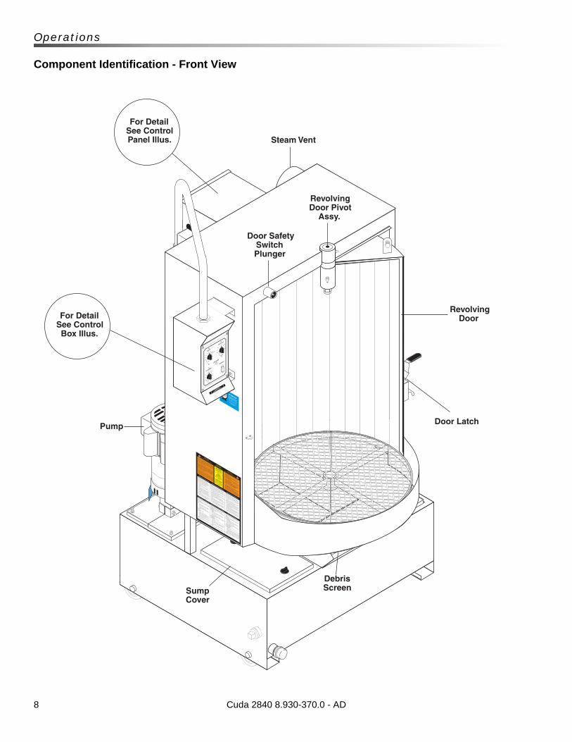
For Detail See Control Panel Illus.
For Detail See Control Box Illus.
Steam Vent
Door Safety Switch Plunger
Revolving Door Pivot
Assy.
Revolving Door
Debris ScreenSump
Cover
Door LatchPump
9
Operations
Component Identification - Rear View
KEEPDRY
This is a heated parts cleaner.
Use only nonflammable, non-
combustible, w
ater-based cleaning compounds in
this m
achine.
Do not fill or contaminate with any flammable or combustib
le
material such as gasolin
e, alcohol, mineral spirit
s, etc. Drain parts
to be cleaned of any combustib
le or flammable m
aterial b
efore
placing inside cabinet. F
ailure to
observe this warning will
create
an extremely hazardous conditio
n.
Este es un limpiador de parte
s que se calienta. Utilice sola-
mente en esta máquina componentes de lim
pieza base agua, no
inflamables y no combustibles. N
o llenar o
contaminar con algún
material in
flamable como, gasolin
a, alcohol, esencias m
inerales,
etc. Drene las parte
s a ser limpiadas de cualquier c
ombustible o
material inflamable antes de intro
ducir en el gabinete. Si
descuida observar estas precauciones, pueden crearse condicio-
nes extremadamente pelig
rosas.
Ce nettoyeur de pièces est chauffé
. Utiliser dans cet appareil
seulement des netto
yeurs à base d’eau, non combustib
les et non
inflammables. Ne pas y ajouter o
u contaminer avec des m
atériaux
combustibles te
ls: gasolin
e, alcool, etc. Vider le
s pièces contenant
des matéria
ux combustibles ou in
flammables avant de le
s placer
à l’intérie
ur du cabinet. N
e pas observer ces avertis
sements peut
créer des situ
ations ris
quées.
HOT WATER
Before opening lid, w
ait 5
seconds to allo
w spray
arm/tu
rntable to stop
spinning.
AGUA
CALIENTE
Antes de abrir la ta
pa,
espere 5 segundos para
que la barra ro
tatoria se
detenga.
EAU CHAUDE
Avant d’ouvrir
le couvert,
attendez 5 secondes pour
permettre
au bras vaporisa-
teur/plaque to
urnante d’arrêter
de tourner.
WARNING
PRECAUCION / ADVERTISSEMENT
CAUTION
CUIDADO / ATTENTION
OPERATING INSTRUCTIONS
INSTRUCCIONESDE OPERACION
INSTRUCTIONS D’OPÉRATION
IMPORTANT: Before operating th
is machine,
completely familiarize yourself w
ith instruction
manual provided. Only authorized and properly
instructed individuals should operate th
is machine.
Before loading parts onto tu
rntable/ basket, b
e cer-
tain the pump is off a
nd not running and th
e wash
solutions are at operating te
mperature.
1. Fill t
ank with water and cleaning solution.
Water level should be 2" b
elow the access doors.
Check daily.
2. Program heater ti
mer for d
esired perio
d of
operation. Allow tim
e for unit to
preheat cleaning
solution.
3. Open door/lid
and place articles to
be clean onto
basket/turntable. B
e certain no parts
protrude
through the botto
m or beyond th
e sides of the
basket/turntable. D
o not exceed the specified
height or w
eight limit fo
r this spray wash cabinet.
4. Close door/lid
and latch securely. With m
achine
set to wash, tu
rn “wash cycle” tim
er to th
e desired
cleaning time. P
ump will start a
nd run until t
ime
has expired.
5. Before opening th
e door/lid, tu
rn wash cycle timer
off and wait 5
seconds for machine to
stop spin-
ning. This will allow steam to
escape the cabinet
and excess water to drain fro
m your parts
.
IMPORTANTE: Antes de oparar e
l equipo, familia
rícese com-
pletamente con el manual de operación que se incluye. S
olo
personal autorizado y debidamente capacitado debe oparar
éste equipo. Antes de abrir
la puerta/cubierta
o las piezas de
carga sobre la tornamesa/canasta, a
segúrese de que la bomba
esté apagada y sin funcionar, y
que las soluciones de limpieza
estén a temperatura de fu
ncionamiento.
1. Llene el depósito con agua y la solución para limpieza. E
l
nivel del agua debe estar 2
" por d
ebajo de las puerta de ac-
ceso. Verifique el nive
l diariamente.
2. Programe el Temporizador d
el calentador para el perío
do de
operación deseado. Deje pasar u
n tiempo para que la unidad
precaliente la solución para limpieza.
3. Abra la puerta
/tapa y coloque las piezas a lavar e
n la tor-
namesa/canasta, asegúrese de que ninguna pieza so-
brepase el fondo ni el perím
etro de la to
rnamesa. No exceda
los limites especificados de peso y altura para el gabinete de
lavado.
4. Cierre
la puerta/ta
pa y asegure el candado. Con la m
áquina
en posición de lavar, ajuste el te
mporizador de “ciclo de
lavado” al tie
mpo deseado. La bomba arrancará y fu
ncionará
durante el tiempo seleccionado.
5. Antes de abrir
la puerta/cubierta
, apague el te
mporizador del
ciclo de lavado y espere 5 segundos para que la máquina
deje de girar. Esto perm
itirá que el va
por salga del gabinete y
el exceso de agua drene de las piezas.
IMPORTANT: Avant d
’utiliser c
ette m
achine, familia
risez-
vous complètement avec le manuel d’instru
ction fourni. Cette
machine devrait être
utilisée seulement p
ar du personnel
autorisé et form
é. Avant l’o
uverture de la porte
/du couvercle
ou du chargement des pièces sur la
table to
urnante/le panier,
s’assurer que la pompe est e
n position arrê
t et n
e fonctionne
pas et que les solutions de lavage sont à
température de
fonctionnement.
1. Remplir l
e réservo
ir d’eau et d
’une solution de nettoyage.
Le niveau d’eau doit s
e trouver à
5 cm (2 po) s
ous les
portes d’accès. V
érifier quotidiennement.
2. Programmer le
minuterie
de chauffage de l’appareil p
our
la période de fonctionnement souhaitée. P
révoir du te
mps
pour que l’a
ppareil préchauffe
la solution de nettoyage.
3. Ouvrir
la porte/couvert e
t placez les artic
les à être lavé
sur le panier/p
laque tournante. A
ssurez-vous qu’il n
’y est
aucune pièce dépassant le painer o
u dans le fond au-delà
du painer/plaque to
urnante.
4. Ferm
ez la porte/couvert e
t verro
uillez de façon sécurita
ire.
La machine prête pour le
lavage, tournez le m
inuteur “wash
cycle” au te
mps de la lavage désiré. La pompe fonctionnera
jusqu’à ce que temps sélectionné soit é
coulé.
5. Avant d
’ouvrir la porte
/le couvercle, mettre
la minuterie
du
cycle de lavage à l’arrê
t et a
ttendre pendant 5
secondes que
l’appareil s’arrê
te de tourner. C
ela permettra
à la vapeur d
e
s’échapper du cabinet e
t à l’e
xcès d’eau de s’écouler de vo
s
pièces.
WARNING
PRECAUCION / ADVERTISSEMENT
• Machine m
ust be connected to
a properly sized
lockable disconnect.
• Installatio
n must c
omply with NEC code.
• For s
upply connection, use wire
s acceptable for
at least 9
0 degrees C.
• Do not u
se below grade floor or g
rade level.
The following schedule is based on average use.
Higher usage m
ay require m
ore frequent m
ainte-
nance.
IMPORTANT: Be sure electric
al supply is OFF be-
fore draining sump. Only qualified personnel should
service this m
achine.
DAILY:
• Check water le
vel in th
e sump daily. Topping
off the water d
aily will prevent d
amage to th
e
heater element.
• Remove and clean debris screen.
• Visually check for p
lugged nozzles. Remove
and clean if needed. R
einstall in th
e exact orig
i-
nal position.
WEEKLY:
• Grease/oil d
oor hinges.
MONTHLY:
• Perfo
rmvisual check of tu
rntable drive chain.
• Drain wash solution fro
m sump, remove sand/
grit fro
m bottom of th
e sump. Care should be
taken to avoid bending or d
amaging heater ele-
ment durin
g the cleaning process.
• When sump has been cleaned and re
filled with
water, add th
e recommended quantity
of deter-
gent for your m
achine.
NOTE: Dissolve
cleaning powder into warm
water
before adding the m
anufacturer’s recommended
amount to th
e tank.
8.922-402.0
• La m
áquina debe estar conectada a un enchufe
eléctrico de segurid
ad.
• La in
stalación debe cumplir con el código NEC.
• Para las conexiones de alim
entación, use cablea-
do para al menos 90 grados centíg
rados.
No utilice por d
ebajo del nivel d
el piso.
• L’a
ppareil doit ê
tre connecté à un sectio
nneur
verrouilla
ble de taille
appropriée.
• L’in
stallation doit s
e conformer a
u code NEC.
• Pour le
raccordement d
e l’alim
entation, u
tiliser d
es
fils pouvant accepter a
u moins 90 degrés Celsius.
Ne pas utiliser u
n calibre ou un grade in
férieur.
Le tableau suiva
nt est fo
ndé sur une utilis
ation moyenne.
Une utilisation plus im
portante peut exiger u
n entretien plus
fréquent.
IMPORTANT : S’assurer q
ue le système électrique est à
l’arrê
t
avant de vider le
réservo
ir. Seul le
personnel qualifié doit ré-
parer cet a
ppareil.
QUOTIDIENNEMENT:
• Vérifier q
uotidiennement le nive
au d’eau dans le rés-
ervoir.
Le remplissage quotidien d’eau perm
et d’éviter
d’endommager l’élément chauffant.
• Démonter e
t nettoyer le
filtre à débris.
• Vérifier v
isuellement si des buses sont bouchées/ob-
struées. D
émonter et n
ettoyer, le cas échéant. R
éinstaller
dans la position initia
le exacte.
HEBDOMADAIREMENT:
• Graisser/h
uiler les pentures/charnières de la porte
.
MENSUELLEMENT:
• Procéder à
un contrôle visuel de la chaîne d’entra
înement
de la table to
urnante.
• Assécher la
solution de lavage du réservo
ir, et e
nlever tout
sable/gravier se tro
uvant au fond. D
es précautions doivent
être prises pour é
viter de plier/c
ourber l’élément chauffant
ou de l’endommager a
u cours du processus de nettoyage.
• Lorsque le ré
servoir a
été nettoyé et rempli d
’eau, ajouter la
quantité de détergent r
ecommandée pour votre
appareil.
NOTE: Bien dissoudre la poudre dans l’e
au chaude avant
d’ajouter dans le ré
servoir.
El plan de mantenimiento que se presenta a continuación, está
basado en un uso promedio del equipo. Un uso más fr
ecuente o
severo puede requerir
un mantenimiento más frecuente.
IMPORTANTE: Asegúrese de que el sistema eléctric
o esté
APAGADO antes de vaciar e
l cárter. S
ólo personal calificado
debe reparar e
sta máquina.
DIARIAMENTE:
• Compruebe el nive
l del agua en el cárter d
iariamente.
Mantener el nive
l adecuado del agua evitará dañar el
elemento del calentador.
• Retire
y limpie los re
siduos de la criba.
• Compruebe visualmente que las boquilla
s están instaladas
correctamente. R
etire y lim
pie si es necesario. Reinstale en
la posición original exacta.
SEMANALMENTE:
• Lubriq
ue las bisagras de la puerta.
MENSUALMENTE:
• Realice una ve
rificación visual de la cadena de propulsión
de la tornamesa.
• Drene la solución de lim
pieza del cárter, r
etire del fo
ndo de
cárter lo
s sedimentos. Debe te
ner cuidado de no doblar o
dañar el elemento del calentador d
urante el proceso de
limpieza.
• Una ve
z que el cárter e
stá limpio y re
lleno de agua,
agregue la cantidad recomendada de detergente para la
máquina.
NOTA: Disuelva
el detergente en agua caliente antes d
e agregar-
lo al tanque en la ca
ntidad recomendada por e
l fabrica
nte.
MAINTENANCE INSTRUCTIONS
INSTRUCCIONES DE MANTENIMIENTO
DIRECTIVES D’ENTRETIEN
ATTENTION
USE ONLY CUDA APPROVED
DETERGENTS TO EXTEND
LABOR WARRANTY TO 1-YEAR!
MIX DETERGENTS 1 LB (1/2 KG) PER
5-GALLONS (15 LITERS) OF WATER
For CUDA Approved Detergents visit
http://w
ww.cudausa.com or
call 888-319-0882
9.807-513.0
90-DAY LABOR WARRANTY
EXTENDS TO 1-YEAR
WITH EXCLUSIVE USE OF
CUDA DETERGENTS
LIMIT
ED
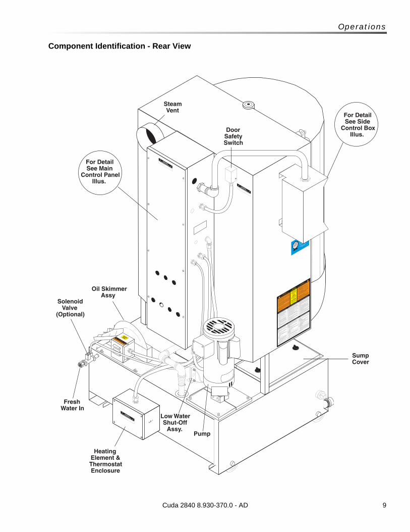
Sump Cover
Solenoid Valve
(Optional)
Fresh Water In
Low Water Shut-Off
Assy.Pump
Heating Element & Thermostat Enclosure
Oil Skimmer Assy
Steam Vent
For Detail See Main
Control Panel Illus.
Door Safety Switch
For Detail See Side
Control Box Illus.
Cuda 2840 8.930-370.0 - AD
10
Operations
Component Identification - Front - Options
Cuda 2840 8.930-370.0 - AD
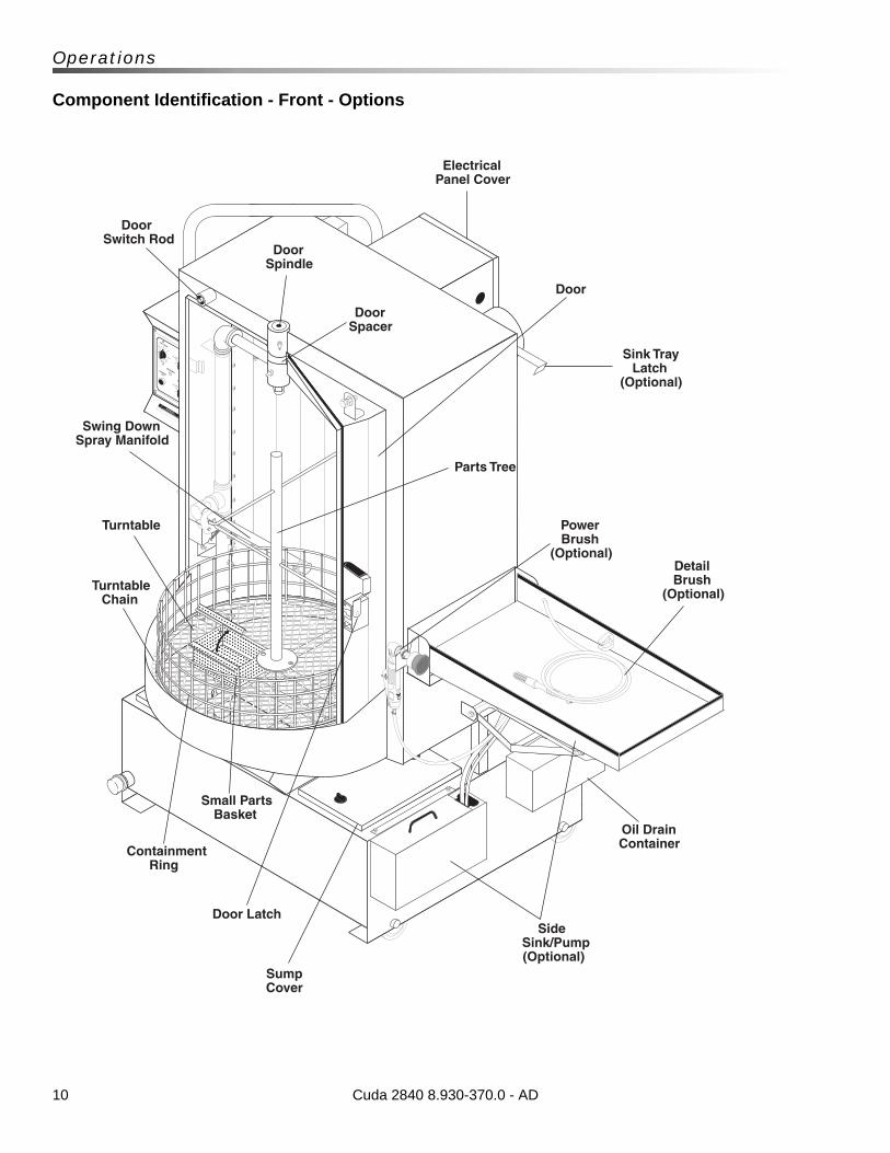
LOW WATER
TURNTABLE
JOG
WASH CYCLE
60
50
40
30
20
10
MINUTES
02
4
6
8
12
10
TURN PAST 2 HEATER
02
4
6
8
12
10
TURN PAST 2 OIL SKIMMER
Door Switch Rod
Door Spacer
Door Spindle
Electrical Panel Cover
Door
Parts Tree
Power Brush
(Optional)Detail Brush
(Optional)
Oil Drain Container
Side Sink/Pump (Optional)
Sump Cover
Door Latch
Small Parts Basket
Containment Ring
Turntable Chain
Turntable
Swing Down Spray Manifold
Sink Tray Latch
(Optional)
11
Operations
Installation
Before You Begin
To prepare to install the machine, choose an unob-structed, level site that allows convenient access for operators and maintenance personnel. Sources for water and electrical power should be located near the installation site. If your machine is equipped with the optional power brush and hand detail brush you must also run a compressed air line to the installation site.
If you have any questions regarding the installation, please contact your dealer or call a customer service representative.
When contacting customer service please refer to the machine identification tag inside the front cover of this manual for detailed machine specifications.
Step 1: Make Electrical ConnectionsNOTE: All electrical installation tasks must be performed by a licensed, professional electrician to ensure safe and proper operation. The installation must comply with the National Electric Code and all applicable state and local codes.
The machine can only operate on the type of elec-trical power indicated on the electrical specifica-tions tag.
Read and understand the electrical specifications tag to determine the electrical power requirements before installing the machine.
Step 2: Configure The 24-hour, 7-day Timers
NOTE: This step is required for machines equipped with an optional 24-hour, 7-day heater timer or a 24-hour, 7-day heater and oil skimmer timer. If your machine does not have a 24-hour, 7-day timer, skip this step.
The optional 24-hour, 7-day heater timer controls the heating system. The optional 24-hour, 7-day heater and oil skimmer timer controls the heating system and the oil skimmer.
The parts washer requires approximately 1 to 2 hours to heat the wash solution to operating temperature, and the oil skimmer requires 10 to 15 minutes to effectively remove oil from the wash solution. Using either timer, you can schedule the heating system to turn on several hours before you begin to use the machine each day. In
addition, the optional 24- hour, 7-day heater and oil skimmer timer allows you to schedule the oil skimmer to operate while the machine sits idle.
The timer is located below the electrical panel inside the main electrical enclosure. To configure the timer, refer to the instruction label inside the timer door.
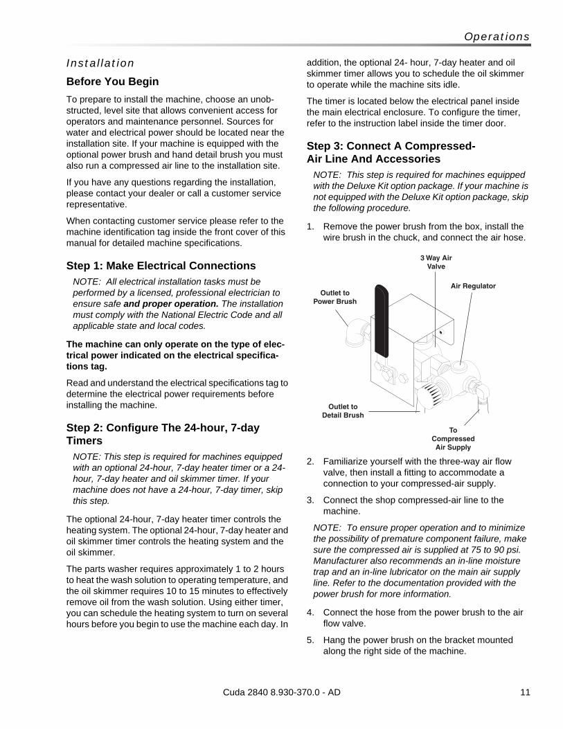
Step 3: Connect A Compressed-Air Line And Accessories
NOTE: This step is required for machines equipped with the Deluxe Kit option package. If your machine is not equipped with the Deluxe Kit option package, skip the following procedure.
1. Remove the power brush from the box, install the wire brush in the chuck, and connect the air hose.
2. Familiarize yourself with the three-way air flow valve, then install a fitting to accommodate a connection to your compressed-air supply.
3. Connect the shop compressed-air line to the machine.
NOTE: To ensure proper operation and to minimize the possibility of premature component failure, make sure the compressed air is supplied at 75 to 90 psi. Manufacturer also recommends an in-line moisture trap and an in-line lubricator on the main air supply line. Refer to the documentation provided with the power brush for more information.
4. Connect the hose from the power brush to the air flow valve.
5. Hang the power brush on the bracket mounted along the right side of the machine.
Cuda 2840 8.930-370.0 - AD
Outlet to Power Brush
Air Regulator
3 Way Air Valve
To Compressed Air Supply
Outlet to Detail Brush
12
Operations
Step 4: Connect A Water LineNOTE: This step is required for machines equipped with the optional automatic water fill feature. If your machine does not have this option, skip this step.
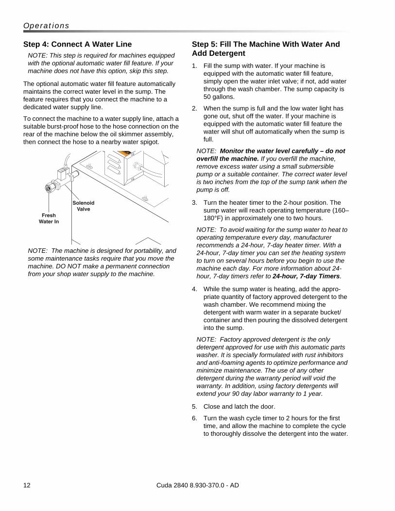
The optional automatic water fill feature automatically maintains the correct water level in the sump. The feature requires that you connect the machine to a dedicated water supply line.
To connect the machine to a water supply line, attach a suitable burst-proof hose to the hose connection on the rear of the machine below the oil skimmer assembly, then connect the hose to a nearby water spigot.
NOTE: The machine is designed for portability, and some maintenance tasks require that you move the machine. DO NOT make a permanent connection from your shop water supply to the machine.
Step 5: Fill The Machine With Water And Add Detergent
1. Fill the sump with water. If your machine is equipped with the automatic water fill feature, simply open the water inlet valve; if not, add water through the wash chamber. The sump capacity is 50 gallons.
2. When the sump is full and the low water light has gone out, shut off the water. If your machine is equipped with the automatic water fill feature the water will shut off automatically when the sump is full.
NOTE: Monitor the water level carefully – do not overfill the machine. If you overfill the machine, remove excess water using a small submersible pump or a suitable container. The correct water level is two inches from the top of the sump tank when the pump is off.
3. Turn the heater timer to the 2-hour position. The sump water will reach operating temperature (160–180°F) in approximately one to two hours.
NOTE: To avoid waiting for the sump water to heat to operating temperature every day, manufacturer recommends a 24-hour, 7-day heater timer. With a 24-hour, 7-day timer you can set the heating system to turn on several hours before you begin to use the machine each day. For more information about 24-hour, 7-day timers refer to 24-hour, 7-day Timers.
4. While the sump water is heating, add the appro-priate quantity of factory approved detergent to the wash chamber. We recommend mixing the detergent with warm water in a separate bucket/container and then pouring the dissolved detergent into the sump.
NOTE: Factory approved detergent is the only detergent approved for use with this automatic parts washer. It is specially formulated with rust inhibitors and anti-foaming agents to optimize performance and minimize maintenance. The use of any other detergent during the warranty period will void the warranty. In addition, using factory detergents will extend your 90 day labor warranty to 1 year.
5. Close and latch the door.
6. Turn the wash cycle timer to 2 hours for the first time, and allow the machine to complete the cycle to thoroughly dissolve the detergent into the water.
Cuda 2840 8.930-370.0 - AD
Fresh Water In
Solenoid Valve
13
Operations
7. (If Optional Deluxe Kit Installed):
After the machine stops, remove the right sump cover and transfer approximately two gallons of wash solution into the detail sump using a small submersible pump or a suitable container.
WARNING: Hot cleaning solution could cause serious injury. Always wear rubber gloves and approved eye protection when handling hot cleaning solution.
8. Replace all sump covers.
When the machine stops, and after the wash water reaches operating temperature, it is ready for use.
Refer to Section 3: Operation for complete operating instructions.
Cuda 2840 8.930-370.0 - AD
14
Operations
Operation
Main Operating Components
Familiarize yourself with the main operating components before operating the machine.
Control Panel
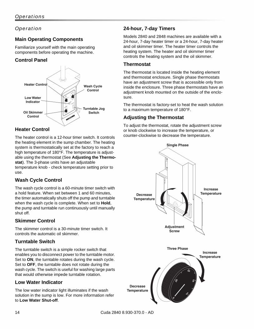
Heater Control
The heater control is a 12-hour timer switch. It controls the heating element in the sump chamber. The heating system is thermostatically set at the factory to reach a high temperature of 180°F. The temperature is adjust-able using the thermostat (See Adjusting the Thermo-stat). The 3-phase units have an adjustable temperature knob - check temperature setting prior to use.
Wash Cycle Control
The wash cycle control is a 60-minute timer switch with a hold feature. When set between 1 and 60 minutes, the timer automatically shuts off the pump and turntable when the wash cycle is complete. When set to Hold, the pump and turntable run continuously until manually shut off.
Skimmer Control
The skimmer control is a 30-minute timer switch. It controls the automatic oil skimmer.
Turntable Switch
The turntable switch is a simple rocker switch that enables you to disconnect power to the turntable motor. Set to ON, the turntable rotates during the wash cycle. Set to OFF, the turntable does not rotate during the wash cycle. The switch is useful for washing large parts that would otherwise impede turntable rotation.
Low Water Indicator
The low water indicator light illuminates if the wash solution in the sump is low. For more information refer to Low Water Shut-off.
24-hour, 7-day Timers
Models 2840 and 2848 machines are available with a 24-hour, 7-day heater timer or a 24-hour, 7-day heater and oil skimmer timer. The heater timer controls the heating system. The heater and oil skimmer timer controls the heating system and the oil skimmer.
Thermostat
The thermostat is located inside the heating element and thermostat enclosure. Single phase thermostats have an adjustment screw that is accessible only from inside the enclosure. Three phase thermostats have an adjustment knob mounted on the outside of the enclo-sure.
The thermostat is factory-set to heat the wash solution to a maximum temperature of 180°F.
Adjusting the Thermostat
To adjust the thermostat, rotate the adjustment screw or knob clockwise to increase the temperature, or counter-clockwise to decrease the temperature.
Cuda 2840 8.930-370.0 - AD
Heater Control
Oil Skimmer Control
Low Water Indicator
Turntable Jog Switch
Wash Cycle Control
Decrease Temperature
Single Phase
Three Phase
Adjustment Screw
Increase TemperatureDecrease
Temperature
Increase Temperature
15
Operations
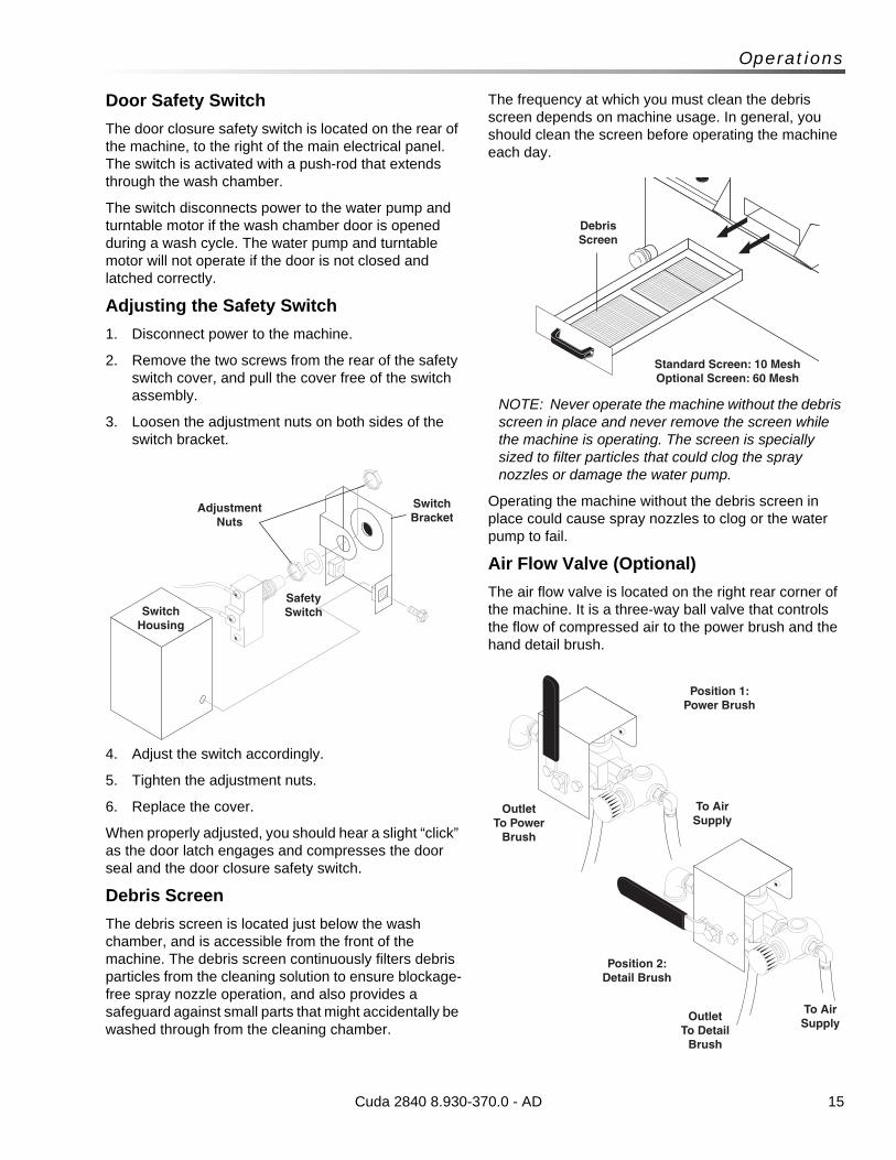
Door Safety Switch
The door closure safety switch is located on the rear of the machine, to the right of the main electrical panel. The switch is activated with a push-rod that extends through the wash chamber.
The switch disconnects power to the water pump and turntable motor if the wash chamber door is opened during a wash cycle. The water pump and turntable motor will not operate if the door is not closed and latched correctly.
Adjusting the Safety Switch
1. Disconnect power to the machine.
2. Remove the two screws from the rear of the safety switch cover, and pull the cover free of the switch assembly.
3. Loosen the adjustment nuts on both sides of the switch bracket.
4. Adjust the switch accordingly.
5. Tighten the adjustment nuts.
6. Replace the cover.
When properly adjusted, you should hear a slight “click” as the door latch engages and compresses the door seal and the door closure safety switch.
Debris Screen
The debris screen is located just below the wash chamber, and is accessible from the front of the machine. The debris screen continuously filters debris particles from the cleaning solution to ensure blockage-free spray nozzle operation, and also provides a safeguard against small parts that might accidentally be washed through from the cleaning chamber.
The frequency at which you must clean the debris screen depends on machine usage. In general, you should clean the screen before operating the machine each day.
NOTE: Never operate the machine without the debris screen in place and never remove the screen while the machine is operating. The screen is specially sized to filter particles that could clog the spray nozzles or damage the water pump.
Operating the machine without the debris screen in place could cause spray nozzles to clog or the water pump to fail.
Air Flow Valve (Optional)
The air flow valve is located on the right rear corner of the machine. It is a three-way ball valve that controls the flow of compressed air to the power brush and the hand detail brush.
Cuda 2840 8.930-370.0 - AD
SwitchHousing
SafetySwitch
Adjustment Nuts
SwitchBracket
DebrisScreen
Standard Screen: 10 MeshOptional Screen: 60 Mesh
To Air Supply
To Air Supply
Outlet To Detail
Brush
Outlet To Power
Brush
Position 2:Detail Brush
Position 1:Power Brush
16
Operations
Detail Tray and Sump Assembly (Optional)
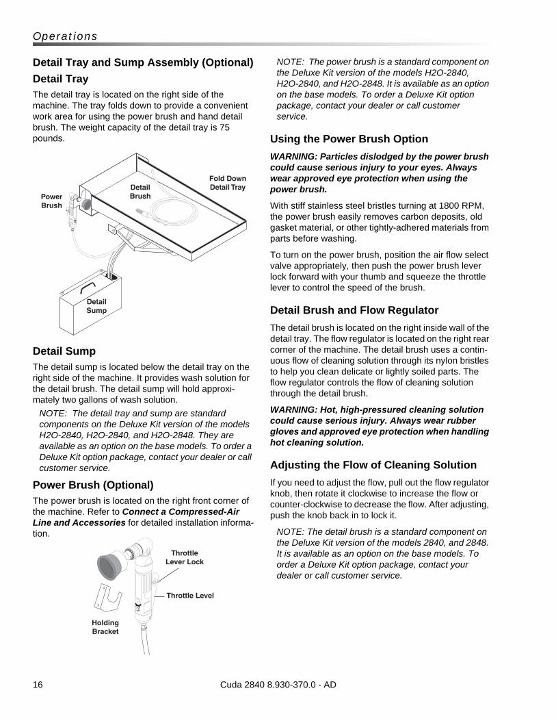
Detail TrayThe detail tray is located on the right side of the machine. The tray folds down to provide a convenient work area for using the power brush and hand detail brush. The weight capacity of the detail tray is 75 pounds.
Detail SumpThe detail sump is located below the detail tray on the right side of the machine. It provides wash solution for the detail brush. The detail sump will hold approxi-mately two gallons of wash solution.
NOTE: The detail tray and sump are standard components on the Deluxe Kit version of the models H2O-2840, H2O-2840, and H2O-2848. They are available as an option on the base models. To order a Deluxe Kit option package, contact your dealer or call customer service.
Power Brush (Optional)The power brush is located on the right front corner of the machine. Refer to Connect a Compressed-Air Line and Accessories for detailed installation informa-tion.
NOTE: The power brush is a standard component on the Deluxe Kit version of the models H2O-2840, H2O-2840, and H2O-2848. It is available as an option on the base models. To order a Deluxe Kit option package, contact your dealer or call customer service.
Using the Power Brush Option
WARNING: Particles dislodged by the power brush could cause serious injury to your eyes. Always wear approved eye protection when using the power brush.
With stiff stainless steel bristles turning at 1800 RPM, the power brush easily removes carbon deposits, old gasket material, or other tightly-adhered materials from parts before washing.
To turn on the power brush, position the air flow select valve appropriately, then push the power brush lever lock forward with your thumb and squeeze the throttle lever to control the speed of the brush.
Detail Brush and Flow Regulator
The detail brush is located on the right inside wall of the detail tray. The flow regulator is located on the right rear corner of the machine. The detail brush uses a contin-uous flow of cleaning solution through its nylon bristles to help you clean delicate or lightly soiled parts. The flow regulator controls the flow of cleaning solution through the detail brush.
WARNING: Hot, high-pressured cleaning solution could cause serious injury. Always wear rubber gloves and approved eye protection when handling hot cleaning solution.
Adjusting the Flow of Cleaning Solution
If you need to adjust the flow, pull out the flow regulator knob, then rotate it clockwise to increase the flow or counter-clockwise to decrease the flow. After adjusting, push the knob back in to lock it.
NOTE: The detail brush is a standard component on the Deluxe Kit version of the models 2840, and 2848. It is available as an option on the base models. To order a Deluxe Kit option package, contact your dealer or call customer service.
Cuda 2840 8.930-370.0 - AD
Fold Down Detail Tray
Power Brush
Detail Sump
Detail Brush
Holding Bracket
ThrottleLever Lock
Throttle Level
17
Operations
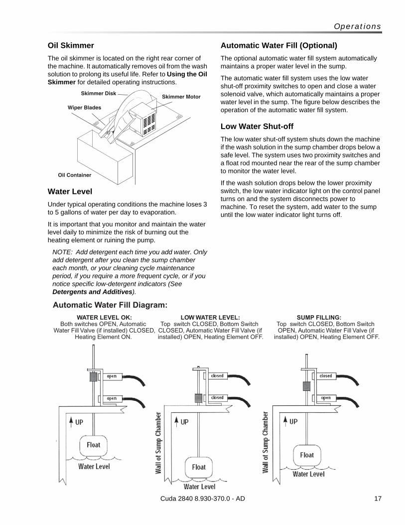
Oil Skimmer
The oil skimmer is located on the right rear corner of the machine. It automatically removes oil from the wash solution to prolong its useful life. Refer to Using the Oil Skimmer for detailed operating instructions.
Water Level
Under typical operating conditions the machine loses 3 to 5 gallons of water per day to evaporation.
It is important that you monitor and maintain the water level daily to minimize the risk of burning out the heating element or ruining the pump.
NOTE: Add detergent each time you add water. Only add detergent after you clean the sump chamber each month, or your cleaning cycle maintenance period, if you require a more frequent cycle, or if you notice specific low-detergent indicators (See Detergents and Additives).
Automatic Water Fill (Optional)
The optional automatic water fill system automatically maintains a proper water level in the sump.
The automatic water fill system uses the low water shut-off proximity switches to open and close a water solenoid valve, which automatically maintains a proper water level in the sump. The figure below describes the operation of the automatic water fill system.
Low Water Shut-off
The low water shut-off system shuts down the machine if the wash solution in the sump chamber drops below a safe level. The system uses two proximity switches and a float rod mounted near the rear of the sump chamber to monitor the water level.
If the wash solution drops below the lower proximity switch, the low water indicator light on the control panel turns on and the system disconnects power to machine. To reset the system, add water to the sump until the low water indicator light turns off.
Cuda 2840 8.930-370.0 - AD
Skimmer MotorSkimmer Disk
Wiper Blades
Oil Container
WATER LEVEL OK:Both switches OPEN, Automatic
Water Fill Valve (if installed) CLOSED, Heating Element ON.
LOW WATER LEVEL:Top switch CLOSED, Bottom Switch
CLOSED, Automatic Water Fill Valve (if installed) OPEN, Heating Element OFF.
SUMP FILLING:Top switch CLOSED, Bottom Switch OPEN, Automatic Water Fill Valve (if
installed) OPEN, Heating Element OFF.
Automatic Water Fill Diagram:
18
Operations
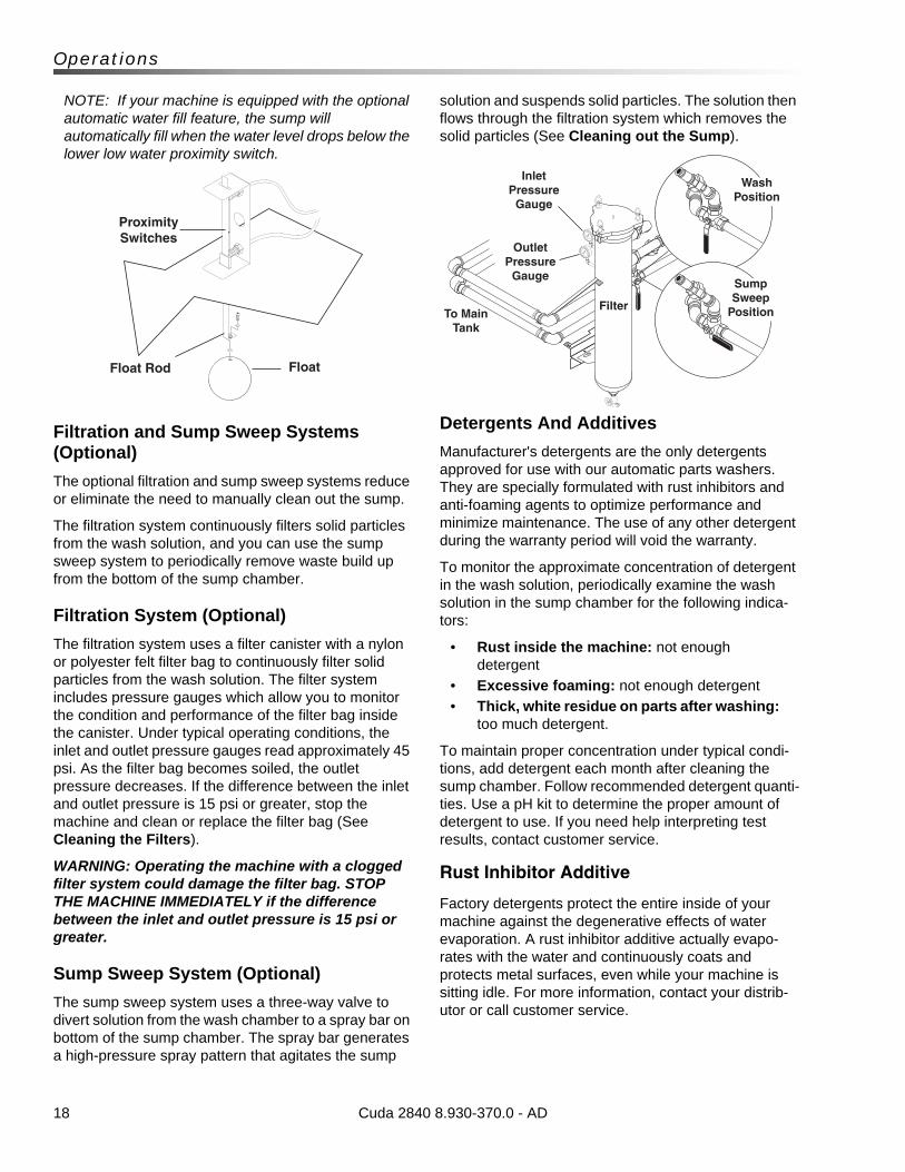
NOTE: If your machine is equipped with the optional automatic water fill feature, the sump will automatically fill when the water level drops below the lower low water proximity switch.
Filtration and Sump Sweep Systems (Optional)
The optional filtration and sump sweep systems reduce or eliminate the need to manually clean out the sump.
The filtration system continuously filters solid particles from the wash solution, and you can use the sump sweep system to periodically remove waste build up from the bottom of the sump chamber.
Filtration System (Optional)
The filtration system uses a filter canister with a nylon or polyester felt filter bag to continuously filter solid particles from the wash solution. The filter system includes pressure gauges which allow you to monitor the condition and performance of the filter bag inside the canister. Under typical operating conditions, the inlet and outlet pressure gauges read approximately 45 psi. As the filter bag becomes soiled, the outlet pressure decreases. If the difference between the inlet and outlet pressure is 15 psi or greater, stop the machine and clean or replace the filter bag (See Cleaning the Filters).
WARNING: Operating the machine with a clogged filter system could damage the filter bag. STOP THE MACHINE IMMEDIATELY if the difference between the inlet and outlet pressure is 15 psi or greater.
Sump Sweep System (Optional)
The sump sweep system uses a three-way valve to divert solution from the wash chamber to a spray bar on bottom of the sump chamber. The spray bar generates a high-pressure spray pattern that agitates the sump
solution and suspends solid particles. The solution then flows through the filtration system which removes the solid particles (See Cleaning out the Sump).
Detergents And Additives
Manufacturer's detergents are the only detergents approved for use with our automatic parts washers. They are specially formulated with rust inhibitors and anti-foaming agents to optimize performance and minimize maintenance. The use of any other detergent during the warranty period will void the warranty.
To monitor the approximate concentration of detergent in the wash solution, periodically examine the wash solution in the sump chamber for the following indica-tors:
• Rust inside the machine: not enough detergent
• Excessive foaming: not enough detergent
• Thick, white residue on parts after washing: too much detergent.
To maintain proper concentration under typical condi-tions, add detergent each month after cleaning the sump chamber. Follow recommended detergent quanti-ties. Use a pH kit to determine the proper amount of detergent to use. If you need help interpreting test results, contact customer service.
Rust Inhibitor Additive
Factory detergents protect the entire inside of your machine against the degenerative effects of water evaporation. A rust inhibitor additive actually evapo-rates with the water and continuously coats and protects metal surfaces, even while your machine is sitting idle. For more information, contact your distrib-utor or call customer service.
Cuda 2840 8.930-370.0 - AD
Float Rod Float
Proximity Switches
Inlet Pressure
Gauge
Outlet Pressure
Gauge
To Main Tank
Filter
Sump Sweep
Position
Wash Position
19
Operations
Preparing The Machine For Use
Before you begin to wash parts, it is important that you properly prepare the machine. Before you begin to use the machine each day:
• check the water level and add water to the sump tank if necessary;
• check sump water cleanliness and run skimmer as-needed to clean sump water surface;
• heat the water to operating temperature;
• add detergent if necessary (see Detergents);
• verify that none of the spray nozzles are clogged; and
• clean the debris screen.
Washing Parts
The following procedure assumes that the heater is on and the sump water is at operating temperature.
To wash parts, perform the following procedure.
WARNING: Hot, high-pressured cleaning solution could cause serious injury. Always wear rubber gloves and approved eye protection when loading and unloading the machine.
1. Load parts into the machine.
Load large, heavy parts directly onto the turntable.
Secure large, light parts (valve covers for example) to the turntable using suitable rubber tie-downs.
Load small, light parts into the small parts basket.
NOTE: For optimum cleaning performance, provide a slight clearance between parts to allow adequate flow of cleaning solution around and between them.
2. Close and latch the door.
3. Set the wash cycle timer to between 1 and 60 minutes for a timed wash cycle, or set it to Hold for a continuous wash.
4. When the machine automatically stops (or after you manually stop the wash cycle), open the door and wait a few moments to allow the parts to cool and dry before removing them. Most parts will flash-dry in seconds.
Shutting Down The Machine
To shut down the machine at the end of the day:
• set the wash cycle timer to OFF;
• set the heater timer to OFF; and
• shut off the compressed air at the supply line (if installed).
WARNING: If the heater is left on unattended, the wash solution could evaporate and the oil and grease in the sump chamber could catch fire.
• For periods of extended shut-down, disconnect all power to the machine.
NOTE: Perform rust preventative treatment on mild steel units prior to extended storage.
• If your machine is equipped with an optional 24-hour, 7-day heater timer, periodically verify the settings to prevent inadvertent unattended operation.
Cuda 2840 8.930-370.0 - AD
20
Maintenance
Maintaining The Machine
To ensure optimum performance and trouble-free oper-ation, observe the following maintenance schedule consistently.
Daily Maintenance• Check the water level; add water if necessary.
• Clean the debris screen.
• Remove oil from the wash solution using the oil skimmer system (See Using the Oil Skimmer System).
Weekly Maintenance• Examine the spray nozzles; clean and align if
necessary (See Cleaning and Aligning the Spray Nozzles).
• Wipe down the exterior of the machine using degreaser spray and a soft, damp cloth. TO PREVENT ELECTRICAL COMPONENT FAILURE, DO NOT SPRAY THE MACHINE WITH WATER.
• Check detergent level to maintain proper con-centration level which decreases as water is added. The pH level of this detergent must be in accordance with the detergent manufacturer's recommendation.
NOTE: Degreaser spray and a damp cloth will usually remove all dirt and grime from the machine. For particularly stubborn soap deposits, use a soft cloth dampened with warm solution from the wash chamber.
Monthly Maintenance• Clean out the sump chamber and detail sump
(See Cleaning out the Sump).• Lubricate the door spindle using high-quality
automotive grease. Add grease until it begins to flow out of the joint beneath the grease fitting, then wipe excess grease from the fitting and the joint.
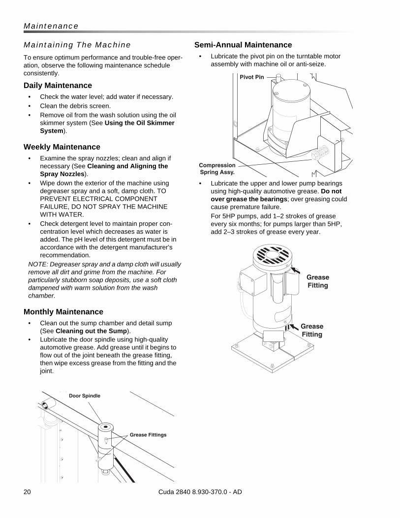
Semi-Annual Maintenance• Lubricate the pivot pin on the turntable motor
assembly with machine oil or anti-seize.
• Lubricate the upper and lower pump bearings using high-quality automotive grease. Do not over grease the bearings; over greasing could cause premature failure.
For 5HP pumps, add 1–2 strokes of grease every six months; for pumps larger than 5HP, add 2–3 strokes of grease every year.
Cuda 2840 8.930-370.0 - AD
Door Spindle
Grease Fittings
Pivot Pin
Compression Spring Assy.
Grease Fitting
Grease Fitting
21
Maintenance
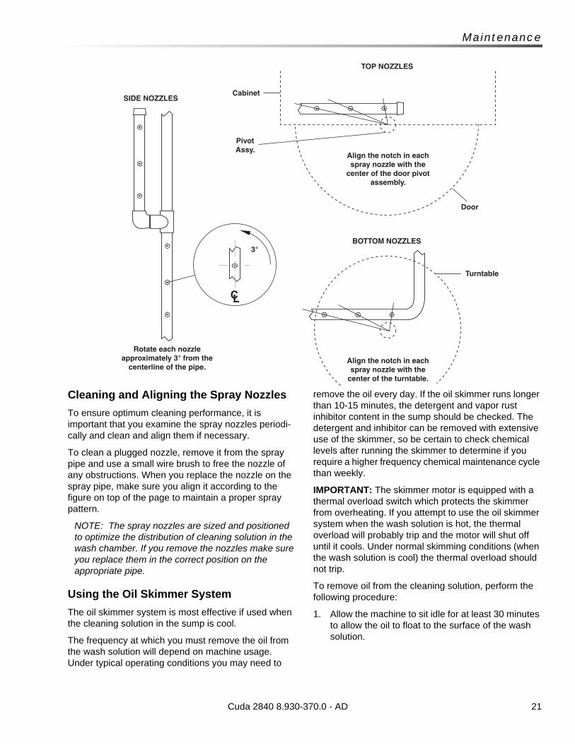
Cleaning and Aligning the Spray Nozzles
To ensure optimum cleaning performance, it is important that you examine the spray nozzles periodi-cally and clean and align them if necessary.
To clean a plugged nozzle, remove it from the spray pipe and use a small wire brush to free the nozzle of any obstructions. When you replace the nozzle on the spray pipe, make sure you align it according to the figure on top of the page to maintain a proper spray pattern.
NOTE: The spray nozzles are sized and positioned to optimize the distribution of cleaning solution in the wash chamber. If you remove the nozzles make sure you replace them in the correct position on the appropriate pipe.
Using the Oil Skimmer System
The oil skimmer system is most effective if used when the cleaning solution in the sump is cool.
The frequency at which you must remove the oil from the wash solution will depend on machine usage. Under typical operating conditions you may need to
remove the oil every day. If the oil skimmer runs longer than 10-15 minutes, the detergent and vapor rust inhibitor content in the sump should be checked. The detergent and inhibitor can be removed with extensive use of the skimmer, so be certain to check chemical levels after running the skimmer to determine if you require a higher frequency chemical maintenance cycle than weekly.
IMPORTANT: The skimmer motor is equipped with a thermal overload switch which protects the skimmer from overheating. If you attempt to use the oil skimmer system when the wash solution is hot, the thermal overload will probably trip and the motor will shut off until it cools. Under normal skimming conditions (when the wash solution is cool) the thermal overload should not trip.
To remove oil from the cleaning solution, perform the following procedure:
1. Allow the machine to sit idle for at least 30 minutes to allow the oil to float to the surface of the wash solution.
Cuda 2840 8.930-370.0 - AD
Align the notch in each spray nozzle with the
center of the turntable.
Rotate each nozzle approximately 3° from the
centerline of the pipe.
BOTTOM NOZZLES
SIDE NOZZLES
TOP NOZZLES
3°
Turntable
Door
Cabinet
Pivot Assy.
Align the notch in each spray nozzle with the
center of the door pivot assembly.
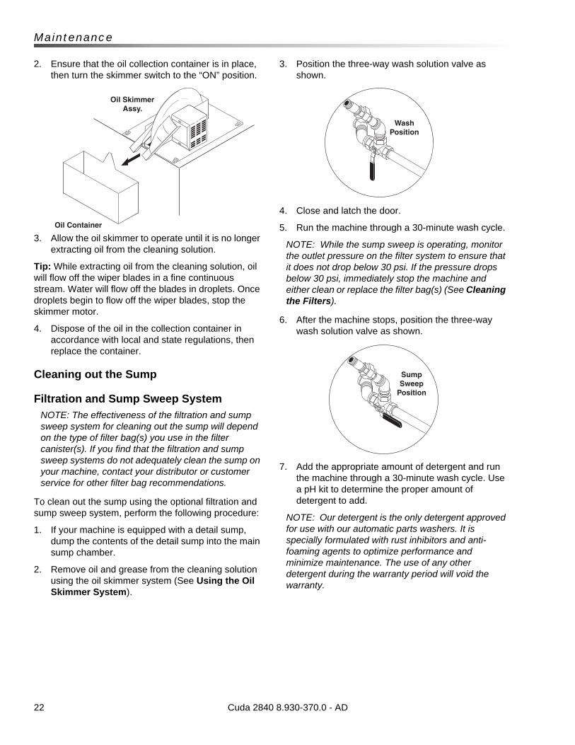
22
Maintenance
2. Ensure that the oil collection container is in place, then turn the skimmer switch to the “ON” position.
3. Allow the oil skimmer to operate until it is no longer extracting oil from the cleaning solution.
Tip: While extracting oil from the cleaning solution, oil will flow off the wiper blades in a fine continuous stream. Water will flow off the blades in droplets. Once droplets begin to flow off the wiper blades, stop the skimmer motor.
4. Dispose of the oil in the collection container in accordance with local and state regulations, then replace the container.
Cleaning out the Sump
Filtration and Sump Sweep SystemNOTE: The effectiveness of the filtration and sump sweep system for cleaning out the sump will depend on the type of filter bag(s) you use in the filter canister(s). If you find that the filtration and sump sweep systems do not adequately clean the sump on your machine, contact your distributor or customer service for other filter bag recommendations.
To clean out the sump using the optional filtration and sump sweep system, perform the following procedure:
1. If your machine is equipped with a detail sump, dump the contents of the detail sump into the main sump chamber.
2. Remove oil and grease from the cleaning solution using the oil skimmer system (See Using the Oil Skimmer System).
3. Position the three-way wash solution valve as shown.
4. Close and latch the door.
5. Run the machine through a 30-minute wash cycle.
NOTE: While the sump sweep is operating, monitor the outlet pressure on the filter system to ensure that it does not drop below 30 psi. If the pressure drops below 30 psi, immediately stop the machine and either clean or replace the filter bag(s) (See Cleaning the Filters).
6. After the machine stops, position the three-way wash solution valve as shown.
7. Add the appropriate amount of detergent and run the machine through a 30-minute wash cycle. Use a pH kit to determine the proper amount of detergent to add.
NOTE: Our detergent is the only detergent approved for use with our automatic parts washers. It is specially formulated with rust inhibitors and anti-foaming agents to optimize performance and minimize maintenance. The use of any other detergent during the warranty period will void the warranty.
Cuda 2840 8.930-370.0 - AD
Wash Position
Sump Sweep
Position
Oil Container
Oil Skimmer Assy.
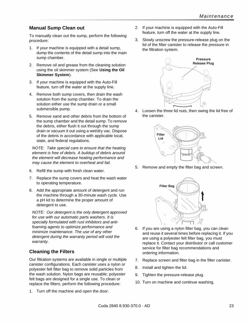
23
Maintenance
Manual Sump Clean out
To manually clean out the sump, perform the following procedure:
1. If your machine is equipped with a detail sump, dump the contents of the detail sump into the main sump chamber.
2. Remove oil and grease from the cleaning solution using the oil skimmer system (See Using the Oil Skimmer System).
3. If your machine is equipped with the Auto-Fill feature, turn off the water at the supply line.
4. Remove both sump covers, then drain the wash solution from the sump chamber. To drain the solution either use the sump drain or a small submersible pump.
5. Remove sand and other debris from the bottom of the sump chamber and the detail sump. To remove the debris, either flush it out through the sump drain or vacuum it out using a wet/dry vac. Dispose of the debris in accordance with applicable local, state, and federal regulations.
NOTE: Take special care to ensure that the heating element is free of debris. A buildup of debris around the element will decrease heating performance and may cause the element to overheat and fail.
6. Refill the sump with fresh clean water.
7. Replace the sump covers and heat the wash water to operating temperature.
8. Add the appropriate amount of detergent and run the machine through a 30-minute wash cycle. Use a pH kit to determine the proper amount of detergent to use.
NOTE: Our detergent is the only detergent approved for use with our automatic parts washers. It is specially formulated with rust inhibitors and anti-foaming agents to optimize performance and minimize maintenance. The use of any other detergent during the warranty period will void the warranty.
Cleaning the Filters
Our filtration systems are available in single or multiple canister configurations. Each canister uses a nylon or polyester felt filter bag to remove solid particles from the wash solution. Nylon bags are reusable; polyester felt bags are designed for a single use. To clean or replace the filters, perform the following procedure:
1. Turn off the machine and open the door.
2. If your machine is equipped with the Auto-Fill feature, turn off the water at the supply line.
3. Slowly unscrew the pressure-release plug on the lid of the filter canister to release the pressure in the filtration system.
4. Loosen the three lid nuts, then swing the lid free of the canister.
5. Remove and empty the filter bag and screen.
6. If you are using a nylon filter bag, you can clean and reuse it several times before replacing it. If you are using a polyester felt filter bag, you must replace it. Contact your distributor or call customer service for filter bag recommendations and ordering information.
7. Replace screen and filter bag in the filter canister.
8. Install and tighten the lid.
9. Tighten the pressure-release plug.
10. Turn on machine and continue washing.
Cuda 2840 8.930-370.0 - AD
Pressure Release Plug
Filter Lid
Filter Bag
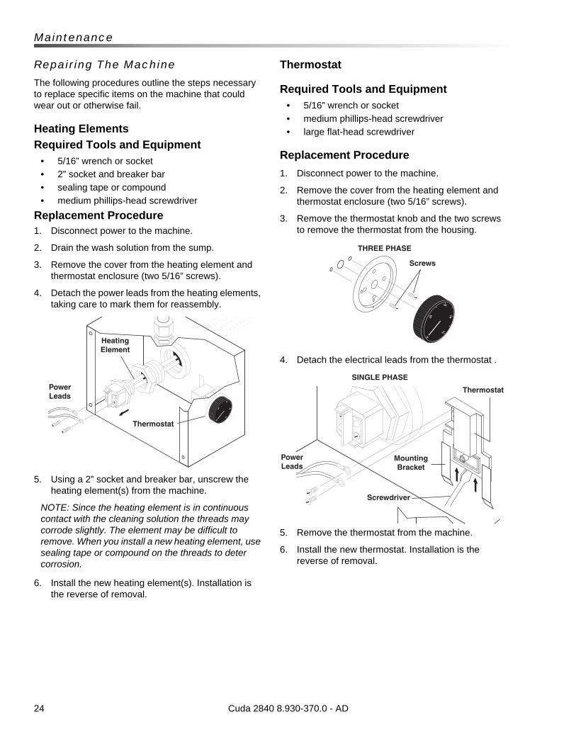
24
Maintenance
Repairing The Machine
The following procedures outline the steps necessary to replace specific items on the machine that could wear out or otherwise fail.
Heating Elements
Required Tools and Equipment• 5/16” wrench or socket
• 2” socket and breaker bar
• sealing tape or compound
• medium phillips-head screwdriver
Replacement Procedure1. Disconnect power to the machine.
2. Drain the wash solution from the sump.
3. Remove the cover from the heating element andthermostat enclosure (two 5/16” screws).
4. Detach the power leads from the heating elements, taking care to mark them for reassembly.
5. Using a 2” socket and breaker bar, unscrew the heating element(s) from the machine.
NOTE: Since the heating element is in continuous contact with the cleaning solution the threads may corrode slightly. The element may be difficult to remove. When you install a new heating element, use sealing tape or compound on the threads to deter corrosion.
6. Install the new heating element(s). Installation is the reverse of removal.
Thermostat
Required Tools and Equipment• 5/16” wrench or socket
• medium phillips-head screwdriver
• large flat-head screwdriver
Replacement Procedure
1. Disconnect power to the machine.
2. Remove the cover from the heating element and thermostat enclosure (two 5/16” screws).
3. Remove the thermostat knob and the two screws to remove the thermostat from the housing.
4. Detach the electrical leads from the thermostat .
5. Remove the thermostat from the machine.
6. Install the new thermostat. Installation is the reverse of removal.
Cuda 2840 8.930-370.0 - AD
Power Leads
Heating Element
Thermostat
Screws
THREE PHASE
Screwdriver
Power Leads
Thermostat
Mounting Bracket
SINGLE PHASE
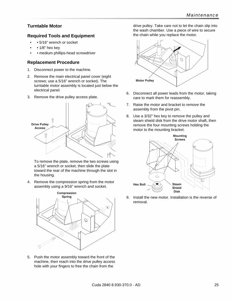
25
Maintenance
Turntable Motor
Required Tools and Equipment• • 5/16” wrench or socket
• • 1/8” hex key
• • medium phillips-head screwdriver
Replacement Procedure
1. Disconnect power to the machine.
2. Remove the main electrical panel cover (eight screws; use a 5/16” wrench or socket). The turntable motor assembly is located just below the electrical panel.
3. Remove the drive pulley access plate.
To remove the plate, remove the two screws using a 5/16” wrench or socket, then slide the plate toward the rear of the machine through the slot in the housing.
4. Remove the compression spring from the motor assembly using a 9/16” wrench and socket.
5. Push the motor assembly toward the front of the machine, then reach into the drive pulley access hole with your fingers to free the chain from the
drive pulley. Take care not to let the chain slip into the wash chamber. Use a piece of wire to secure the chain while you replace the motor.
6. Disconnect all power leads from the motor, taking care to mark them for reassembly.
7. Raise the motor and bracket to remove the assembly from the pivot pin.
8. Use a 3/32” hex key to remove the pulley and steam shield disk from the drive motor shaft, then remove the four mounting screws holding the motor to the mounting bracket.
9. Install the new motor. Installation is the reverse of removal.
Cuda 2840 8.930-370.0 - AD
Drive Pulley Access
Compression Spring
Motor Pulley
Hex Bolt Steam Shield Disk
Mounting Screws
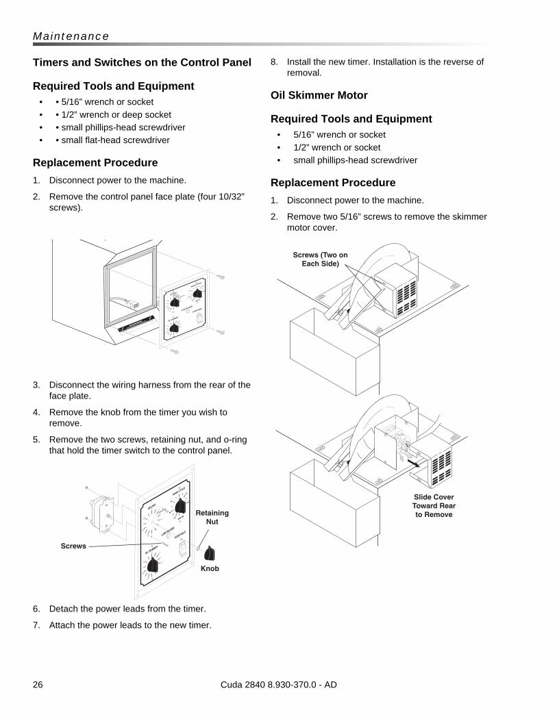
26
Maintenance
Timers and Switches on the Control Panel
Required Tools and Equipment• • 5/16” wrench or socket
• • 1/2” wrench or deep socket
• • small phillips-head screwdriver
• • small flat-head screwdriver
Replacement Procedure
1. Disconnect power to the machine.
2. Remove the control panel face plate (four 10/32” screws).
3. Disconnect the wiring harness from the rear of the face plate.
4. Remove the knob from the timer you wish to remove.
5. Remove the two screws, retaining nut, and o-ring that hold the timer switch to the control panel.
6. Detach the power leads from the timer.
7. Attach the power leads to the new timer.
8. Install the new timer. Installation is the reverse of removal.
Oil Skimmer Motor
Required Tools and Equipment• 5/16” wrench or socket
• 1/2” wrench or socket
• small phillips-head screwdriver
Replacement Procedure
1. Disconnect power to the machine.
2. Remove two 5/16” screws to remove the skimmer motor cover.
Cuda 2840 8.930-370.0 - AD
Screws (Two on Each Side)
Slide Cover Toward Rear to Remove
Screws
Knob
Retaining Nut
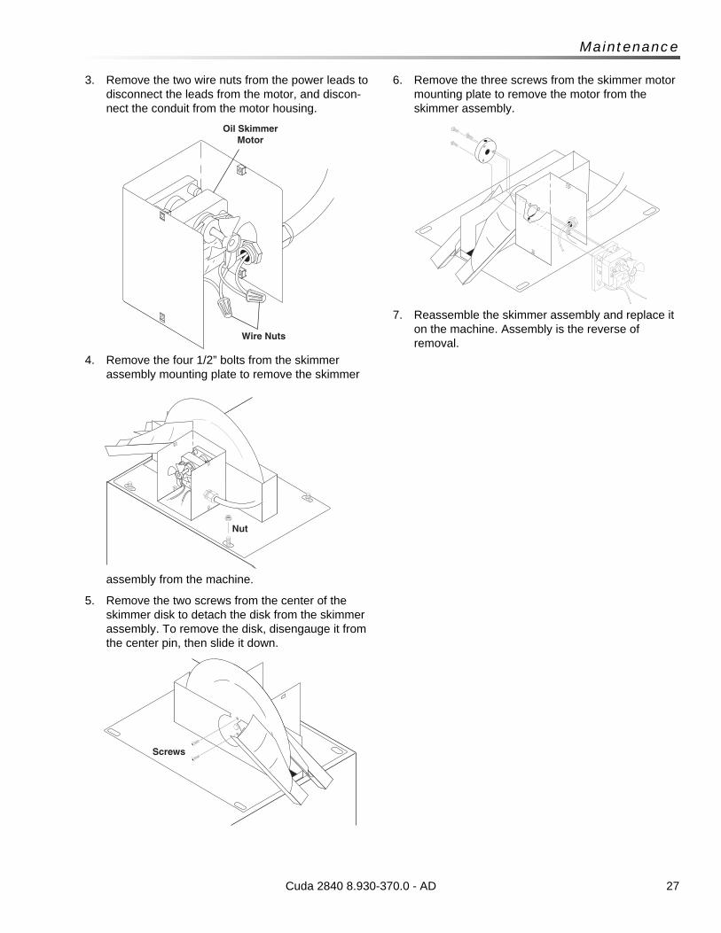
27
Maintenance
3. Remove the two wire nuts from the power leads to disconnect the leads from the motor, and discon-nect the conduit from the motor housing.
4. Remove the four 1/2” bolts from the skimmer assembly mounting plate to remove the skimmer
assembly from the machine.
5. Remove the two screws from the center of the skimmer disk to detach the disk from the skimmer assembly. To remove the disk, disengauge it from the center pin, then slide it down.
6. Remove the three screws from the skimmer motor mounting plate to remove the motor from the skimmer assembly.
7. Reassemble the skimmer assembly and replace it on the machine. Assembly is the reverse of removal.
Cuda 2840 8.930-370.0 - AD
Nut
Screws
Wire Nuts
Oil Skimmer Motor
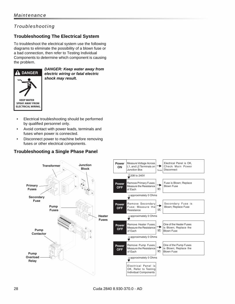
28
Maintenance
Troubleshooting
Troubleshooting The Electrical System
To troubleshoot the electrical system use the following diagrams to eliminate the possibility of a blown fuse or a bad connection, then refer to Testing Individual Components to determine which component is causing the problem.
DANGER: Keep water away from electric wiring or fatal electric shock may result.
• Electrical troubleshooting should be performed by qualified personnel only.
• Avoid contact with power leads, terminals and fuses when power is connected.
• Disconnect power to machine before removing fuses or other electrical components.
Troubleshooting a Single Phase Panel
Cuda 2840 8.930-370.0 - AD
None
Power ON
Power OFF
Power OFF
Power OFF
Power OFF
Measure Voltage Across L1, and L2 Terminals on Junction Box
Electrical Panel is OK, Check Main Power Disconnect
Remove Primary Fuses; Measure the Resistance of Each
Fuse is Blown; Replace Blown Fuse
Remove Secondary Fuse; Measure the Resistance
Secondary Fuse is Blown; Replace Fuse
Remove Heater Fuses; Measure the Resistance of Each
One of the Heater Fuses is Blown; Replace the Blown Fuse
Remove Pump Fuses; Measure the Resistance of Each
One of the Pump Fuses is Blown; Replace the Blown Fuse
Elect r ica l Panel is OK, Refer to Testing Individual Components
208 to 240V
approximately 0 Ohms
approximately 0 Ohms
approximately 0 Ohms
approximately 0 Ohms
GROUND
Junction Block
Transformer
Secondary Fuse
Primary Fuses
Heater Fuses
Pump Fuses
Pump Contactor
Pump Overload
Relay
DANGER
KEEP WATER SPRAY AWAY FROM ELECTRICAL WIRING.
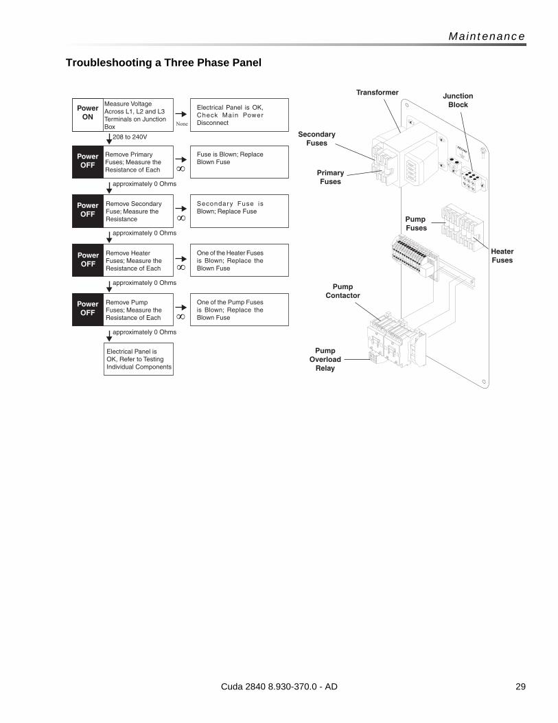
29
Maintenance
Troubleshooting a Three Phase Panel
Cuda 2840 8.930-370.0 - AD
None
Power ON
Power OFF
Power OFF
Power OFF
Power OFF
Measure Voltage Across L1, L2 and L3 Terminals on Junction Box
Electrical Panel is OK, Check Main Power Disconnect
Remove Primary Fuses; Measure the Resistance of Each
Fuse is Blown; Replace Blown Fuse
Remove Secondary Fuse; Measure the Resistance
Secondary Fuse is Blown; Replace Fuse
Remove Heater Fuses; Measure the Resistance of Each
One of the Heater Fuses is Blown; Replace the Blown Fuse
Remove Pump Fuses; Measure the Resistance of Each
One of the Pump Fuses is Blown; Replace the Blown Fuse
Electrical Panel is OK, Refer to Testing Individual Components
208 to 240V
approximately 0 Ohms
approximately 0 Ohms
approximately 0 Ohms
approximately 0 Ohms
GROUND
Junction Block
Transformer
Secondary Fuses
Primary Fuses
Heater Fuses
Pump Fuses
Pump Overload
Relay
Pump Contactor
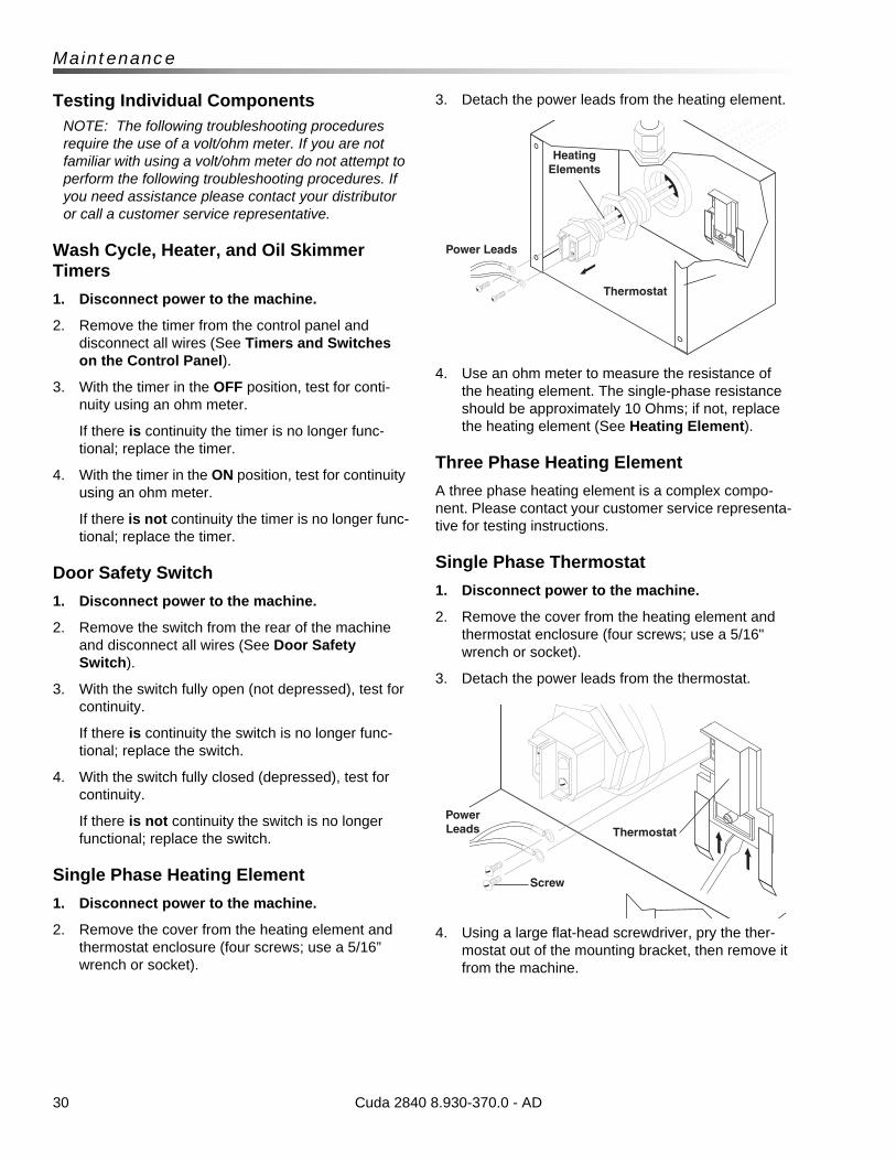
30
Maintenance
Testing Individual ComponentsNOTE: The following troubleshooting procedures require the use of a volt/ohm meter. If you are not familiar with using a volt/ohm meter do not attempt to perform the following troubleshooting procedures. If you need assistance please contact your distributor or call a customer service representative.
Wash Cycle, Heater, and Oil Skimmer Timers
1. Disconnect power to the machine.
2. Remove the timer from the control panel and disconnect all wires (See Timers and Switches on the Control Panel).
3. With the timer in the OFF position, test for conti-nuity using an ohm meter.
If there is continuity the timer is no longer func-tional; replace the timer.
4. With the timer in the ON position, test for continuity using an ohm meter.
If there is not continuity the timer is no longer func-tional; replace the timer.
Door Safety Switch
1. Disconnect power to the machine.
2. Remove the switch from the rear of the machine and disconnect all wires (See Door Safety Switch).
3. With the switch fully open (not depressed), test for continuity.
If there is continuity the switch is no longer func-tional; replace the switch.
4. With the switch fully closed (depressed), test for continuity.
If there is not continuity the switch is no longer functional; replace the switch.
Single Phase Heating Element
1. Disconnect power to the machine.
2. Remove the cover from the heating element and thermostat enclosure (four screws; use a 5/16” wrench or socket).
3. Detach the power leads from the heating element.
4. Use an ohm meter to measure the resistance of the heating element. The single-phase resistance should be approximately 10 Ohms; if not, replace the heating element (See Heating Element).
Three Phase Heating Element
A three phase heating element is a complex compo-nent. Please contact your customer service representa-tive for testing instructions.
Single Phase Thermostat
1. Disconnect power to the machine.
2. Remove the cover from the heating element and thermostat enclosure (four screws; use a 5/16" wrench or socket).
3. Detach the power leads from the thermostat.
4. Using a large flat-head screwdriver, pry the ther-mostat out of the mounting bracket, then remove it from the machine.
Cuda 2840 8.930-370.0 - AD
Heating Elements
Power Leads
Thermostat
Power Leads Thermostat
Screw
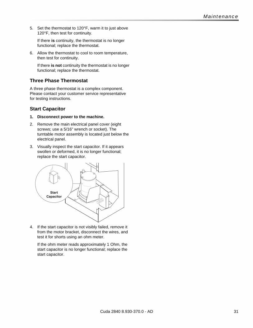
31
Maintenance
5. Set the thermostat to 120°F, warm it to just above 120°F, then test for continuity.
If there is continuity, the thermostat is no longer functional; replace the thermostat.
6. Allow the thermostat to cool to room temperature, then test for continuity.
If there is not continuity the thermostat is no longer functional; replace the thermostat.
Three Phase Thermostat
A three phase thermostat is a complex component. Please contact your customer service representative for testing instructions.
Start Capacitor
1. Disconnect power to the machine.
2. Remove the main electrical panel cover (eight screws; use a 5/16” wrench or socket). The turntable motor assembly is located just below the electrical panel.
3. Visually inspect the start capacitor. If it appears swollen or deformed, it is no longer functional; replace the start capacitor.
4. If the start capacitor is not visibly failed, remove it from the motor bracket, disconnect the wires, and test it for shorts using an ohm meter.
If the ohm meter reads approximately 1 Ohm, the start capacitor is no longer functional; replace the start capacitor.
Cuda 2840 8.930-370.0 - AD
Start Capacitor
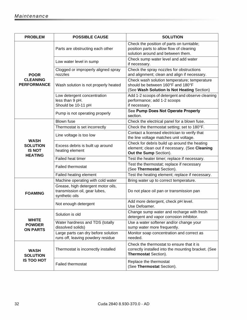
32
Maintenance
PROBLEM POSSIBLE CAUSE SOLUTION
POOR CLEANING
PERFORMANCE
Parts are obstructing each otherCheck the position of parts on turntable; position parts to allow flow of cleaning solution around and between them.
Low water level in sumpCheck sump water level and add water if necessary.
Clogged or improperly aligned spray nozzles
Check the spray nozzles for obstructions and alignment; clean and align if necessary.
Wash solution is not properly heatedCheck wash solution temperature; temperature should be between 160°F and 180°F (See Wash Solution Is Not Heating Section)
Low detergent concentration less than 9 pH. Should be 10-11 pH
Add 1-2 scoops of detergent and observe cleaning performance; add 1-2 scoops if necessary.
Pump is not operating properlySee Pump Does Not Operate Properly
section.
WASH SOLUTION
IS NOT HEATING
Blown fuse Check the electrical panel for a blown fuse.
Thermostat is set incorrectly Check the thermostat setting; set to 180°F.
Line voltage is too lowContact a licensed electrician to verify that the line voltage matches unit voltage.
Excess debris is built up around heating element
Check for debris build up around the heating element; clean out if necessary. (See Cleaning Out the Sump Section).
Failed heat timer Test the heater timer; replace if necessary.
Failed thermostatTest the thermostat; replace if necessary (See Thermostat Section).
Failed heating element Test the heating element; replace if necessary.
FOAMING
Machine operating with cold water Bring water up to correct temperature.
Grease, high detergent motor oils, transmission oil, gear lubes, synthetic oils
Do not place oil pan or transmission pan
Not enough detergentAdd more detergent, check pH level. Use Defoamer.
WHITE POWDER
ON PARTS
Solution is oldChange sump water and recharge with fresh detergent and vapor corrosion inhibitor.
Water hardness and TDS (totally dissolved solids)
Use a water softener and/or change your sump water more frequently.
Large parts can dry before solution runs off, leaving powdery residue
Monitor soap concentration and correct as needed.
WASH SOLUTION
IS TOO HOT
Thermostat is incorrectly installedCheck the thermostat to ensure that it is correctly installed into the mounting bracket. (See Thermostat Section).
Failed thermostatReplace the thermostat (See Thermostat Section).
Cuda 2840 8.930-370.0 - AD
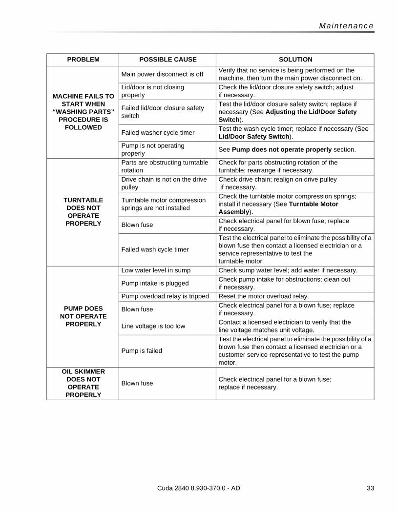
33
Maintenance
PROBLEM POSSIBLE CAUSE SOLUTION
MACHINE FAILS TO START WHEN
“WASHING PARTS” PROCEDURE IS
FOLLOWED
Main power disconnect is offVerify that no service is being performed on the machine, then turn the main power disconnect on.
Lid/door is not closing properly
Check the lid/door closure safety switch; adjust if necessary.
Failed lid/door closure safety switch
Test the lid/door closure safety switch; replace if necessary (See Adjusting the Lid/Door Safety Switch).
Failed washer cycle timerTest the wash cycle timer; replace if necessary (See Lid/Door Safety Switch).
Pump is not operating properly
See Pump does not operate properly section.
TURNTABLE DOES NOT OPERATE
PROPERLY
Parts are obstructing turntable rotation
Check for parts obstructing rotation of the turntable; rearrange if necessary.
Drive chain is not on the drive pulley
Check drive chain; realign on drive pulley if necessary.
Turntable motor compression springs are not installed
Check the turntable motor compression springs; install if necessary (See Turntable Motor Assembly).
Blown fuseCheck electrical panel for blown fuse; replace if necessary.
Failed wash cycle timer
Test the electrical panel to eliminate the possibility of a blown fuse then contact a licensed electrician or a service representative to test the turntable motor.
PUMP DOES NOT OPERATE
PROPERLY
Low water level in sump Check sump water level; add water if necessary.
Pump intake is pluggedCheck pump intake for obstructions; clean out if necessary.
Pump overload relay is tripped Reset the motor overload relay.
Blown fuseCheck electrical panel for a blown fuse; replaceif necessary.
Line voltage is too lowContact a licensed electrician to verify that the line voltage matches unit voltage.
Pump is failed
Test the electrical panel to eliminate the possibility of a blown fuse then contact a licensed electrician or a customer service representative to test the pump motor.
OIL SKIMMER DOES NOT OPERATE
PROPERLY
Blown fuseCheck electrical panel for a blown fuse; replace if necessary.
Cuda 2840 8.930-370.0 - AD
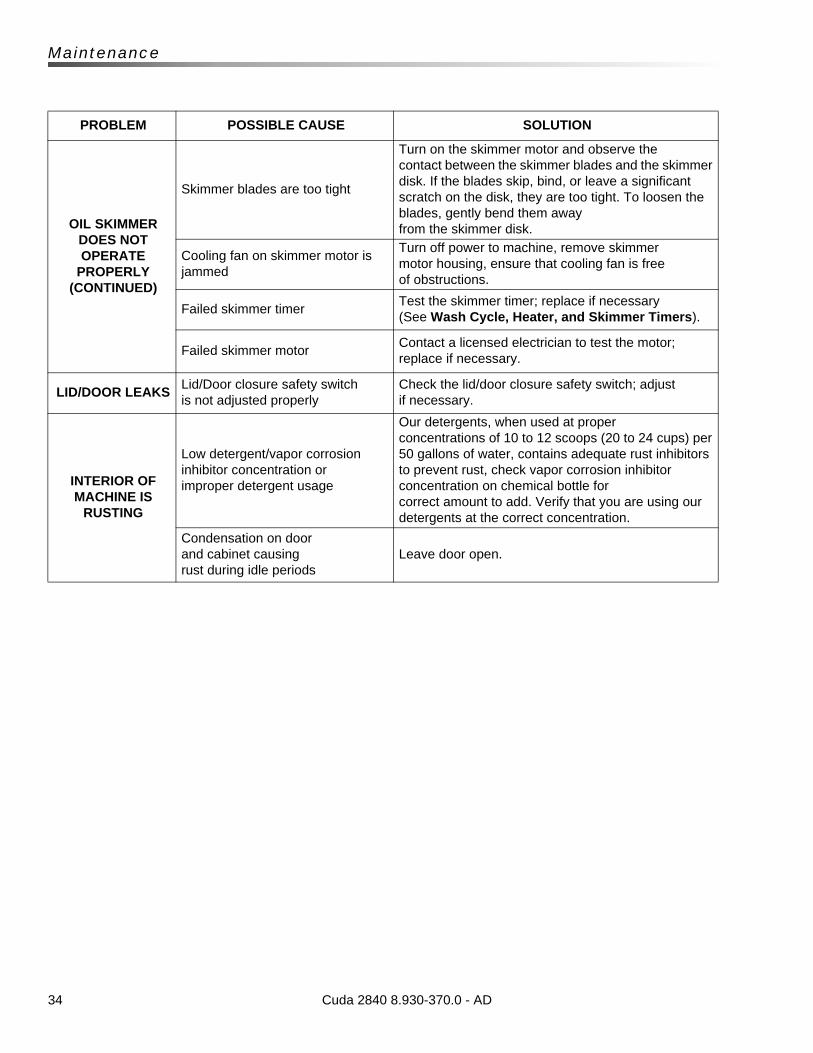
34
Maintenance
PROBLEM POSSIBLE CAUSE SOLUTION
OIL SKIMMER DOES NOTOPERATE
PROPERLY (CONTINUED)
Skimmer blades are too tight
Turn on the skimmer motor and observe the contact between the skimmer blades and the skimmer disk. If the blades skip, bind, or leave a significant scratch on the disk, they are too tight. To loosen the blades, gently bend them away from the skimmer disk.
Cooling fan on skimmer motor is jammed
Turn off power to machine, remove skimmer motor housing, ensure that cooling fan is free of obstructions.
Failed skimmer timerTest the skimmer timer; replace if necessary (See Wash Cycle, Heater, and Skimmer Timers).
Failed skimmer motorContact a licensed electrician to test the motor; replace if necessary.
LID/DOOR LEAKSLid/Door closure safety switch is not adjusted properly
Check the lid/door closure safety switch; adjust if necessary.
INTERIOR OF MACHINE IS
RUSTING
Low detergent/vapor corrosion inhibitor concentration or improper detergent usage
Our detergents, when used at proper concentrations of 10 to 12 scoops (20 to 24 cups) per 50 gallons of water, contains adequate rust inhibitors to prevent rust, check vapor corrosion inhibitor concentration on chemical bottle for correct amount to add. Verify that you are using our detergents at the correct concentration.
Condensation on door and cabinet causing rust during idle periods
Leave door open.
Cuda 2840 8.930-370.0 - AD
35
Parts
Parts
1.043-395.0, 1.043-416.0, 1.043-417.0, 1.043-418.0, 1.043-419.0, 1.043-420.0, 1.043-492.0, 1.043-493.0, 1.043-494.0, 1.043-496.0, 1.043-497.0, 1.043-498.0
Cuda 2840
Cuda 2840 8.930-370.0 - AD
36
Cuda 2840 Front
Cuda 2840 8.930-370.0 - AD
LOW WATER
TURNTABLE
JOG
WASH CYCLE
60
50
40
30
20
10
MINUTES
02
4
6
8
12
10
TURN PAST 2 HEATER
02
4
6
8
12
10
TURN PAST 2 OIL SKIMMER
1
2
3
4
5
6
7
8
9
10
11
12
13
14
15
16
17
18 19
21
22
23
2627
28
29
3031
32
33
3435
36
37
38
39
4142
43
44
29
2827
32
3334
33
34
35
Field Installed
25
45
47
47
20
40
2431
19
For Detail See Latch
Assy
37Cuda 2840 8.930-370.0 - AD
Cuda 2840 Front
REF PART NO. QTY DESCRIPTION NOTES
1 8.915-132.0 1 ASSY, CABINET 2840
- 8.922-457.0 1 WLMT, CABINET, 2840, SS
2 8.915-131.0 1 ASSY, DOOR 2840
- 8.922-462.0 1 WLMT, DOOR, 2840, SS
3 8.915-141.0 1 ASSY, TURNTABLE 2840/2848
- 8.921-910.0 1 WLMT, TURNTABLE, 28 OD, SS
4 8.915-606.0 1 ASSY, DEBRIS TRAY
- 8.921-919.0 1 WLMT, DEBRIS TRAY, SS
5 8.921-957.0 1 COVER, SUMP 10" X 16.5" W/O GAUGE, SS
6 9.804-346.0 1 BEARING, BALL UPPER TT 6206RS
7 9.804-347.0 1 BEARING, BALL LOWER TT 6007RS
8 8.713-234.0 1 SPINDLE, TURNTABLE 2216-2848
- 8.753-685.0 1 SPINDLE, TURNTABLE CHAIN DRIVE, SS
9 8.712-909.0 1 WASHER LOCK 3/4
- 8.749-817.0 1 WASHER 3/4" SPLIT RING, LOCK, SS
10 8.712-855.0 1 BOLT, 3/4", -16 X 1-1/2" GRADE 2 HEX HEAD
- 8.754-309.0 1 SCREW, 3/4" X 1-1/2", HH, CS, SS
11 8.712-875.0 4 PIN COTTER 1/8" X 1-1/4"
12 8.712-939.0 4 PIN CLEVIS 3/4" X 3-1/2"
13 8.713-037.0 4 WHEEL POLYOLEFIN 4" X 2" X 3/4" BORE
14 9.804-378.0 2 LATCH, SUMP COVER
15 8.706-349.0 1 PIPE, CAP, 1-1/2" GALV.
- 8.749-821.0 1 PIPE, CAP, 1-1/2" STAINLESS STEEL
16 8.712-928.0 1 SPINDLE, DOOR
- 8.753-684.0 1 BOLT, SHOULDER DOOR PIVOT, SS
17 8.930-238.0 1 SPACER, DOOR HUB
- 8.753-836.0 1 SPACER, DOOR HUB, SS
18 8.713-821.0 1 NUT, NYLOC, 5/8"-18 ZINC GR5
- 8.754-317.0 1 NUT, 5/8"-18 NYLOC, 316 SS
19 8.712-852.0 2 GREASE FITTING
20 9.804-203.0 1 HANDLE, STRAINER
21 8.915-133.0 1 ANGLE, DOOR SIDE 2840
- 8.922-465.0 1 DOOR, SIDE, ANGLE, 2840, SS
22 8.915-200.0 1 ANGLE, DOOR TOP 2840
- 8.921-950.0 1 ANGLE, DOOR TOP 2840/2848, SS
23 8.712-951.0 54" FOAM STRIP 1/8" X 1" ADHESIVE BACK
24 8.714-150.0 1 CHAIN W/CONNECTOR LINK
- 8.923.114.0 1 CHAIN W/CONNECTOR LINK, SS
25 9.802-807.0 3 WASHER, 3/8" SAE FLAT
- 8.754-310.0 3 WASHER, 3/8" 18-8, SAE FLAT, SS
26 8.915-388.0 60" SEAL, BULB TYPE EPDM SIDE PROFILE
27 8.718-794.0 15 SCREW, 10/32" X 3/4", HEX
- 8.754-306.0 15 SCREW, 10/32" X 3/4", HEX WASHER HEAD SS
38
Cuda 2840 Front
28 9.802-802.0 15 WASHER, 1/4" FLAT, SAE
- 8.718-965.0 15 WASHER, 1/4" FLAT, SAE, SS
29 9.804-567.0 15 NUT, 10/32", ESNA
- 8.754-307.0 15 NUT, 10/32", ESNA, SS
30 8.713-038.0 6 WHEEL, TRACK
- 8.753-682.0 6 WHEEL, TRACK, SS
31 8.713-266.0 12 E-CLIP, 1/4" MILD STEEL
- 8.753-763.0 12 E-CLIP, 1/4" STAINLESS STEEL
32 8.718-603.0 3 BOLT, 1/4" X 3/4", NC HH SS
33 8.718-965.0 6 WASHER, 1/4", FLAT, SAE, SS
34 9.802-774.0 5 NUT, 1/4", ESNA, NC, SS
35 8.718-568.0 4 WASHER, 1/4" FLAT SS SEALING RUBBER
36 9.802-779.0 3 NUT, 3/8", ESNA, NC
- 9.802-780.0 3 NUT, 3/8", STAINLESS, ESNA, NC
37 8.921-304.0 1 LATCH, SPRAY PIPE
- 8.921-955.0 1 LATCH, SPRAY PIPE, SS
38 8.713-020.0 1 SPRING- EXTENSION. 440 DIA. X 2", 6.5 LB/INCH
Cuda 2840 8.930-370.0 - AD

39Cuda 2840 8.930-370.0 - AD
Cuda 2840 Front
REF PART NO. QTY DESCRIPTION NOTES
39 9.804-373.0 1 U-BOLT, 1/4"-20 PLATED
- 8.754-305.0 1 U-BOLT, 1/4"- 3/8" PIPE, SS
40 8.930-307.0 1 STOP, SPRAY PIPE
- 8.921-959.0 1 STOP, SPRAY PIPE, SS
41 8.713-246.0 2 SCREW -5/16"-18 X 1" SOCKET HEAD
- 8.754-316.0 2 SCREW -5/16"X 1", SHCS, SS
42 8.718-980.0 2 WASHER, 5/16", FLAT, SAE
- 9.802-805.0 2 WASHER, 5/16",18-8, FLAT, SAE, SS
43 9.802-776.0 2 NUT, 5/16", ESNA, NC
- 8.754-314.0 2 NUT, 5/16"-18, FLAT, SAE, SS
44 8.915-388.0 48" SEAL, BULB TYPE EPDM SIDE PROFILE
45 9.801-126.0 1 LABEL, CUDA 24 X 6"
46 8.924-172.0 1 BUCKET, OIL NOT SHOWN
47 8.713-265.0 6 CAP, VINYL BLACK, 1/4" X 3/4" LG
48 8.731-254.0 1 PARTS BASKET -SMALL 8 X 8 X 4 NOT SHOWN
49 8.705-957.0 1 CONTAINMENT RING-28 INCH,MARKED RED NOT SHOWN
50 8.915-124.0 1 PARTS TREE, 4 HOOK, 27" X 24" NOT SHOWN
40
Cuda 2840 Rear
KEEPDRY
GROUND
GROUND
ATTENTION
USE ONLY CUDA APPROVED
DETERGENTS TO EXTEND
LABOR WARRANTY TO 1-YEAR!
MIX DETERGENTS 1 LB (1/2 KG) PER
5-GALLONS (15 LITERS) OF WATER
For CUDA Approved Detergents visit
http://w
ww.cudausa.com or
call 888-319-0882
9.807-513.0
90-DAY LABOR WARRANTY
EXTENDS TO 1-YEAR
WITH EXCLUSIVE USE OF
CUDA DETERGENTS
LIMIT
ED
This is a heated parts cleaner.
Use only nonflammable, non-
combustible, w
ater-based cleaning compounds in
this m
achine.
Do not fill or contaminate with any flammable or combustib
le
material such as gasolin
e, alcohol, mineral spirit
s, etc. Drain parts
to be cleaned of any combustib
le or flammable m
aterial b
efore
placing inside cabinet. F
ailure to
observe this warning will c
reate
an extremely hazardous conditio
n.
Este es un limpiador de parte
s que se calienta. Utilice sola-
mente en esta máquina componentes de lim
pieza base agua, no
inflamables y no combustibles. N
o llenar o
contaminar con algún
material in
flamable como, gasolin
a, alcohol, esencias m
inerales,
etc. Drene las parte
s a ser limpiadas de cualquier c
ombustible o
material inflamable antes de intro
ducir en el gabinete. Si
descuida observar estas precauciones, pueden crearse condicio-
nes extremadamente pelig
rosas.
Ce nettoyeur de pièces est chauffé
. Utiliser dans cet appareil
seulement des netto
yeurs à base d’eau, non combustib
les et non
inflammables. Ne pas y ajouter o
u contaminer avec des m
atériaux
combustibles te
ls: gasolin
e, alcool, etc. Vider le
s pièces contenant
des matéria
ux combustibles ou in
flammables avant de le
s placer
à l’intérie
ur du cabinet. N
e pas observer ces avertis
sements peut
créer des situ
ations ris
quées.
HOT WATER
Before opening lid, w
ait 5
seconds to allo
w spray
arm/tu
rntable to stop
spinning.
AGUA
CALIENTE
Antes de abrir la ta
pa,
espere 5 segundos para
que la barra ro
tatoria se
detenga.
EAU CHAUDE
Avant d’ouvrir
le couvert,
attendez 5 secondes pour
permettre
au bras vaporisa-
teur/plaque to
urnante d’arrêter
de tourner.
WARNING
PRECAUCION / ADVERTISSEMENT
CAUTION
CUIDADO / ATTENTION
OPERATING INSTRUCTIONS
INSTRUCCIONESDE OPERACION
INSTRUCTIONS D’OPÉRATION
IMPORTANT: Before operating th
is machine,
completely familiarize yourself w
ith instruction
manual provided. Only authorized and properly
instructed individuals should operate th
is machine.
Before loading parts onto tu
rntable/ basket, b
e cer-
tain the pump is off a
nd not running and th
e wash
solutions are at operating te
mperature.
1. Fill t
ank with water and cleaning solution.
Water level should be 2" b
elow the access doors.
Check daily.
2. Program heater ti
mer for d
esired perio
d of
operation. Allow tim
e for unit to
preheat cleaning
solution.
3. Open door/lid
and place articles to
be clean onto
basket/turntable. B
e certain no parts
protrude
through the botto
m or beyond th
e sides of the
basket/turntable. D
o not exceed the specified
height or w
eight limit fo
r this spray wash cabinet.
4. Close door/lid
and latch securely. With m
achine
set to wash, tu
rn “wash cycle” tim
er to th
e desired
cleaning time. P
ump will start a
nd run until t
ime
has expired.
5. Before opening th
e door/lid, tu
rn wash cycle timer
off and wait 5
seconds for machine to
stop spin-
ning. This will allow steam to
escape the cabinet
and excess water to drain fro
m your parts
.
IMPORTANTE: Antes de oparar e
l equipo, familia
rícese com-
pletamente con el manual de operación que se incluye. S
olo
personal autorizado y debidamente capacitado debe oparar
éste equipo. Antes de abrir
la puerta/cubierta
o las piezas de
carga sobre la tornamesa/canasta, a
segúrese de que la bomba
esté apagada y sin funcionar, y
que las soluciones de limpieza
estén a temperatura de fu
ncionamiento.
1. Llene el depósito con agua y la solución para limpieza. E
l
nivel del agua debe estar 2
" por d
ebajo de las puerta de ac-
ceso. Verifique el nive
l diariamente.
2. Programe el Temporizador d
el calentador para el perío
do de
operación deseado. Deje pasar u
n tiempo para que la unidad
precaliente la solución para limpieza.
3. Abra la puerta
/tapa y coloque las piezas a lavar e
n la tor-
namesa/canasta, asegúrese de que ninguna pieza so-
brepase el fondo ni el perím
etro de la to
rnamesa. No exceda
los limites especificados de peso y altura para el gabinete de
lavado.
4. Cierre
la puerta/ta
pa y asegure el candado. Con la m
áquina
en posición de lavar, ajuste el te
mporizador de “ciclo de
lavado” al tie
mpo deseado. La bomba arrancará y fu
ncionará
durante el tiempo seleccionado.
5. Antes de abrir
la puerta/cubierta
, apague el te
mporizador del
ciclo de lavado y espere 5 segundos para que la máquina
deje de girar. E
sto permitirá
que el vapor s
alga del gabinete y
el exceso de agua drene de las piezas.
IMPORTANT: Avant d
’utiliser c
ette m
achine, familia
risez-
vous complètement avec le manuel d’instru
ction fourni. Cette
machine devrait être
utilisée seulement p
ar du personnel
autorisé et form
é. Avant l’o
uverture de la porte
/du couvercle
ou du chargement des pièces sur la
table to
urnante/le panier,
s’assurer que la pompe est e
n position arrê
t et n
e fonctionne
pas et que les solutions de lavage sont à
température de
fonctionnement.
1. Remplir l
e réservo
ir d’eau et d
’une solution de nettoyage.
Le niveau d’eau doit s
e trouver à
5 cm (2 po) s
ous les
portes d’accès. V
érifier quotidiennement.
2. Programmer le
minuterie
de chauffage de l’appareil p
our
la période de fonctionnement souhaitée. P
révoir du te
mps
pour que l’a
ppareil préchauffe la solution de nettoyage.
3. Ouvrir
la porte/couvert e
t placez les artic
les à être lavé
sur le panier/p
laque tournante. A
ssurez-vous qu’il n
’y est
aucune pièce dépassant le painer o
u dans le fond au-delà
du painer/plaque to
urnante.
4. Ferm
ez la porte/couvert e
t verro
uillez de façon sécurita
ire.
La machine prête pour le
lavage, tournez le m
inuteur “wash
cycle” au te
mps de la lavage désiré. La pompe fonctionnera
jusqu’à ce que temps sélectionné soit é
coulé.
5. Avant d
’ouvrir la porte
/le couvercle, mettre
la minuterie
du
cycle de lavage à l’arrê
t et a
ttendre pendant 5
secondes que
l’appareil s’arrê
te de tourner. C
ela permettra
à la vapeur d
e
s’échapper du cabinet e
t à l’e
xcès d’eau de s’écouler de vo
s
pièces.
WARNING
PRECAUCION / ADVERTISSEMENT
• Machine m
ust be connected to
a properly sized
lockable disconnect.
• Installatio
n must c
omply with NEC code.
• For s
upply connection, u
se wires acceptable fo
r
at least 9
0 degrees C.
• Do not u
se below grade floor or g
rade level.
The following schedule is based on average use.
Higher usage may re
quire more fre
quent mainte-
nance.
IMPORTANT: Be sure electric
al supply is OFF be-
fore draining sump. Only qualified personnel should
service this m
achine.
DAILY:
• Check water le
vel in th
e sump daily. Topping
off the water d
aily will prevent d
amage to th
e
heater element.
• Remove and clean debris screen.
• Visually check for p
lugged nozzles. Remove
and clean if needed. R
einstall in th
e exact orig
i-
nal position.
WEEKLY:
• Grease/oil d
oor hinges.
MONTHLY:
• Perfo
rm visual check of tu
rntable drive chain.
• Drain wash solution fro
m sump, remove sand/
grit fro
m bottom of th
e sump. Care should be
taken to avoid bending or d
amaging heater ele-
ment durin
g the cleaning process.
• When sump has been cleaned and re
filled with
water, add th
e recommended quantity
of deter-
gent for yo
ur machine.
NOTE: Dissolve
cleaning powder into warm
water
before adding the m
anufacturer’s recommended
amount to th
e tank.
8.922-402.0
• La m
áquina debe estar conectada a un enchufe
eléctrico de segurid
ad.
• La in
stalación debe cumplir con el código NEC.
• Para las conexiones de alim
entación, use cablea-
do para al menos 90 grados centíg
rados.
No utilice por d
ebajo del nivel d
el piso.
• L’a
ppareil doit ê
tre connecté à un sectio
nneur
verrouilla
ble de taille
appropriée.
• L’in
stallation doit s
e conformer a
u code NEC.
• Pour le
raccordement d
e l’alim
entation, u
tiliser d
es
fils pouvant accepter a
u moins 90 degrés Celsius.
Ne pas utiliser u
n calibre ou un grade in
férieur.
Le tableau suivant e
st fondé sur u
ne utilisation m
oyenne.
Une utilisation plus im
portante peut exiger u
n entretien plus
fréquent.
IMPORTANT : S’assurer q
ue le système électrique est à
l’arrê
t
avant de vider le
réservo
ir. Seul le
personnel qualifié doit ré-
parer cet a
ppareil.
QUOTIDIENNEMENT:
• Vérifier q
uotidiennement le nive
au d’eau dans le rés-
ervoir.
Le remplissage quotidien d’eau perm
et d’éviter
d’endommager l’élément chauffa
nt.
• Démonter e
t nettoyer le
filtre à débris.
• Vérifier v
isuellement si des buses sont bouchées/ob-
struées. D
émonter et n
ettoyer, le cas échéant. R
éinstaller
dans la position initia
le exacte.
HEBDOMADAIREMENT:
• Graisser/h
uiler les pentures/charnières de la porte
.
MENSUELLEMENT:
• Procéder à
un contrôle visuel de la chaîne d’entra
înement
de la table to
urnante.
• Assécher la
solution de lavage du réservo
ir, et e
nlever tout
sable/gravier se tro
uvant au fond. D
es précautions doivent
être prises pour é
viter de plier/c
ourber l’élément chauffant
ou de l’endommager a
u cours du processus de nettoyage.
• Lorsque le ré
servoir a
été nettoyé et rempli d
’eau, ajouter la
quantité de détergent r
ecommandée pour votre
appareil.
NOTE: Bien dissoudre la poudre dans l’e
au chaude avant
d’ajouter dans le ré
servoir.
El plan de mantenimiento que se presenta a continuación, está
basado en un uso promedio del equipo. Un uso más fr
ecuente o
severo puede requerir
un mantenimiento más frecuente.
IMPORTANTE: Asegúrese de que el sistema eléctric
o esté
APAGADO antes de vaciar e
l cárter. S
ólo personal calificado
debe reparar e
sta máquina.
DIARIAMENTE:
• Compruebe el nive
l del agua en el cárter d
iariamente.
Mantener el nive
l adecuado del agua evitará dañar el
elemento del calentador.
• Retire
y limpie los re
siduos de la criba.
• Compruebe visualmente que las boquilla
s están instaladas
correctamente. R
etire y lim
pie si es necesario. Reinstale en
la posición original exacta.
SEMANALMENTE:
• Lubriq
ue las bisagras de la puerta.
MENSUALMENTE:
• Realice una ve
rificación visual de la cadena de propulsión
de la tornamesa.
• Drene la solución de lim
pieza del cárter, r
etire del fo
ndo de
cárter lo
s sedimentos. Debe te
ner cuidado de no doblar o
dañar el elemento del calentador d
urante el proceso de
limpieza.
• Una ve
z que el cárter e
stá limpio y re
lleno de agua,
agregue la cantidad recomendada de detergente para la
máquina.
NOTA: Disuelva
el detergente en agua caliente antes de agregar-
lo al tanque en la cantidad re
comendada por el fa
bricante.
MAINTENANCE INSTRUCTIONS
INSTRUCCIONES DE MANTENIMIENTO
DIRECTIVES D’ENTRETIEN
1 2
34
5
7
8
9
10
11
12
13
7715
1617 18
19
3
21
22 23
24
25
2627
2829
30
31
32
33
34
38
39 40
41
4243
44
53
3579
4514
49
15
12
60
14
15
2
56
59
5754
64
63
62 6061 49
55
58
46
For Details, See Control
Panel Exploded Views Pages
42-53
74
75
5
70
68
69
7666
65
71
73
67
36
3737
8283
48
5
48
72
20
49
For Details See TT Motor
PageFor Detail See
Oil Skimmer Page
80
78
51 166
82
Cuda 2840 8.930-370.0 - AD
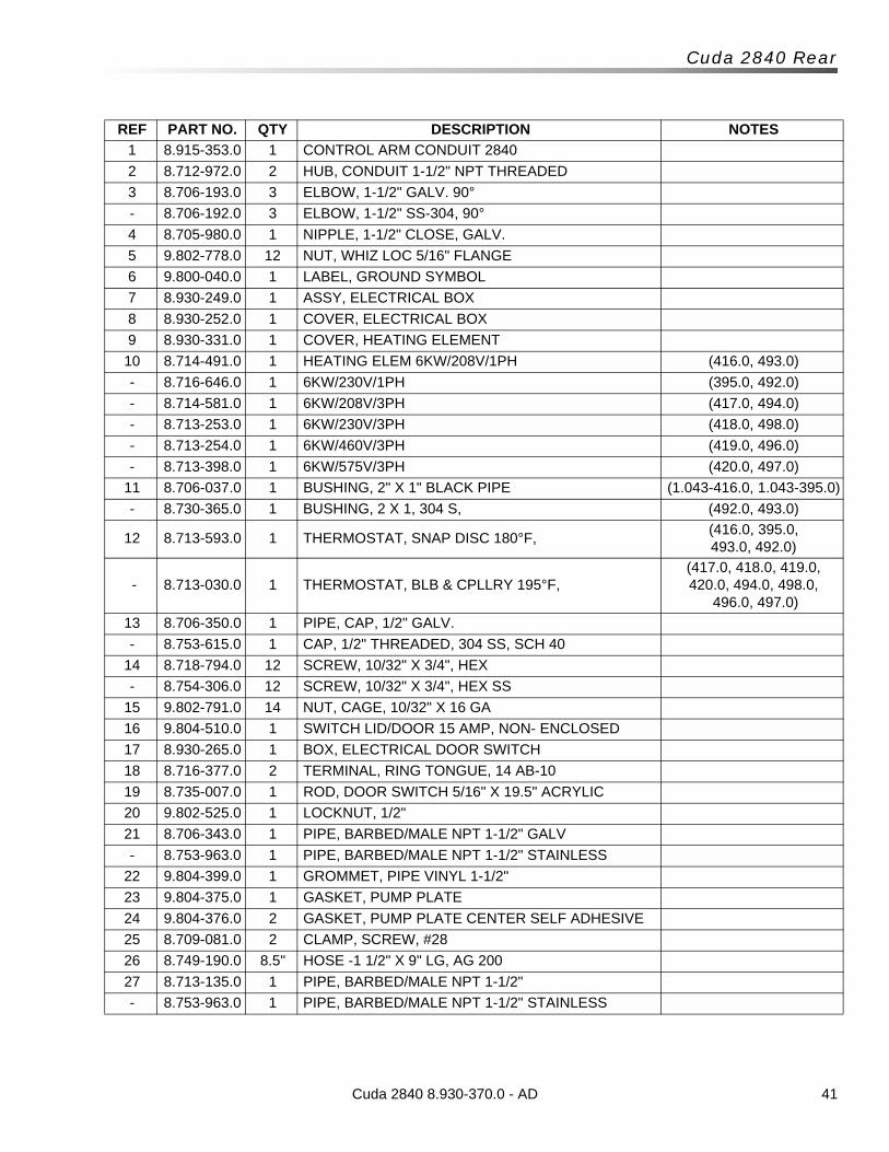
41Cuda 2840 8.930-370.0 - AD
Cuda 2840 Rear
REF PART NO. QTY DESCRIPTION NOTES
1 8.915-353.0 1 CONTROL ARM CONDUIT 2840
2 8.712-972.0 2 HUB, CONDUIT 1-1/2" NPT THREADED
3 8.706-193.0 3 ELBOW, 1-1/2" GALV. 90°
- 8.706-192.0 3 ELBOW, 1-1/2" SS-304, 90°
4 8.705-980.0 1 NIPPLE, 1-1/2" CLOSE, GALV.
5 9.802-778.0 12 NUT, WHIZ LOC 5/16" FLANGE
6 9.800-040.0 1 LABEL, GROUND SYMBOL
7 8.930-249.0 1 ASSY, ELECTRICAL BOX
8 8.930-252.0 1 COVER, ELECTRICAL BOX
9 8.930-331.0 1 COVER, HEATING ELEMENT
10 8.714-491.0 1 HEATING ELEM 6KW/208V/1PH (416.0, 493.0)
- 8.716-646.0 1 6KW/230V/1PH (395.0, 492.0)
- 8.714-581.0 1 6KW/208V/3PH (417.0, 494.0)
- 8.713-253.0 1 6KW/230V/3PH (418.0, 498.0)
- 8.713-254.0 1 6KW/460V/3PH (419.0, 496.0)
- 8.713-398.0 1 6KW/575V/3PH (420.0, 497.0)
11 8.706-037.0 1 BUSHING, 2" X 1" BLACK PIPE (1.043-416.0, 1.043-395.0)
- 8.730-365.0 1 BUSHING, 2 X 1, 304 S, (492.0, 493.0)
12 8.713-593.0 1 THERMOSTAT, SNAP DISC 180°F, (416.0, 395.0, 493.0, 492.0)
- 8.713-030.0 1 THERMOSTAT, BLB & CPLLRY 195°F, (417.0, 418.0, 419.0, 420.0, 494.0, 498.0,
496.0, 497.0)
13 8.706-350.0 1 PIPE, CAP, 1/2" GALV.
- 8.753-615.0 1 CAP, 1/2" THREADED, 304 SS, SCH 40
14 8.718-794.0 12 SCREW, 10/32" X 3/4", HEX
- 8.754-306.0 12 SCREW, 10/32" X 3/4", HEX SS
15 9.802-791.0 14 NUT, CAGE, 10/32" X 16 GA
16 9.804-510.0 1 SWITCH LID/DOOR 15 AMP, NON- ENCLOSED
17 8.930-265.0 1 BOX, ELECTRICAL DOOR SWITCH
18 8.716-377.0 2 TERMINAL, RING TONGUE, 14 AB-10
19 8.735-007.0 1 ROD, DOOR SWITCH 5/16" X 19.5" ACRYLIC
20 9.802-525.0 1 LOCKNUT, 1/2"
21 8.706-343.0 1 PIPE, BARBED/MALE NPT 1-1/2" GALV
- 8.753-963.0 1 PIPE, BARBED/MALE NPT 1-1/2" STAINLESS
22 9.804-399.0 1 GROMMET, PIPE VINYL 1-1/2"
23 9.804-375.0 1 GASKET, PUMP PLATE
24 9.804-376.0 2 GASKET, PUMP PLATE CENTER SELF ADHESIVE
25 8.709-081.0 2 CLAMP, SCREW, #28
26 8.749-190.0 8.5" HOSE -1 1/2" X 9" LG, AG 200
27 8.713-135.0 1 PIPE, BARBED/MALE NPT 1-1/2"
- 8.753-963.0 1 PIPE, BARBED/MALE NPT 1-1/2" STAINLESS
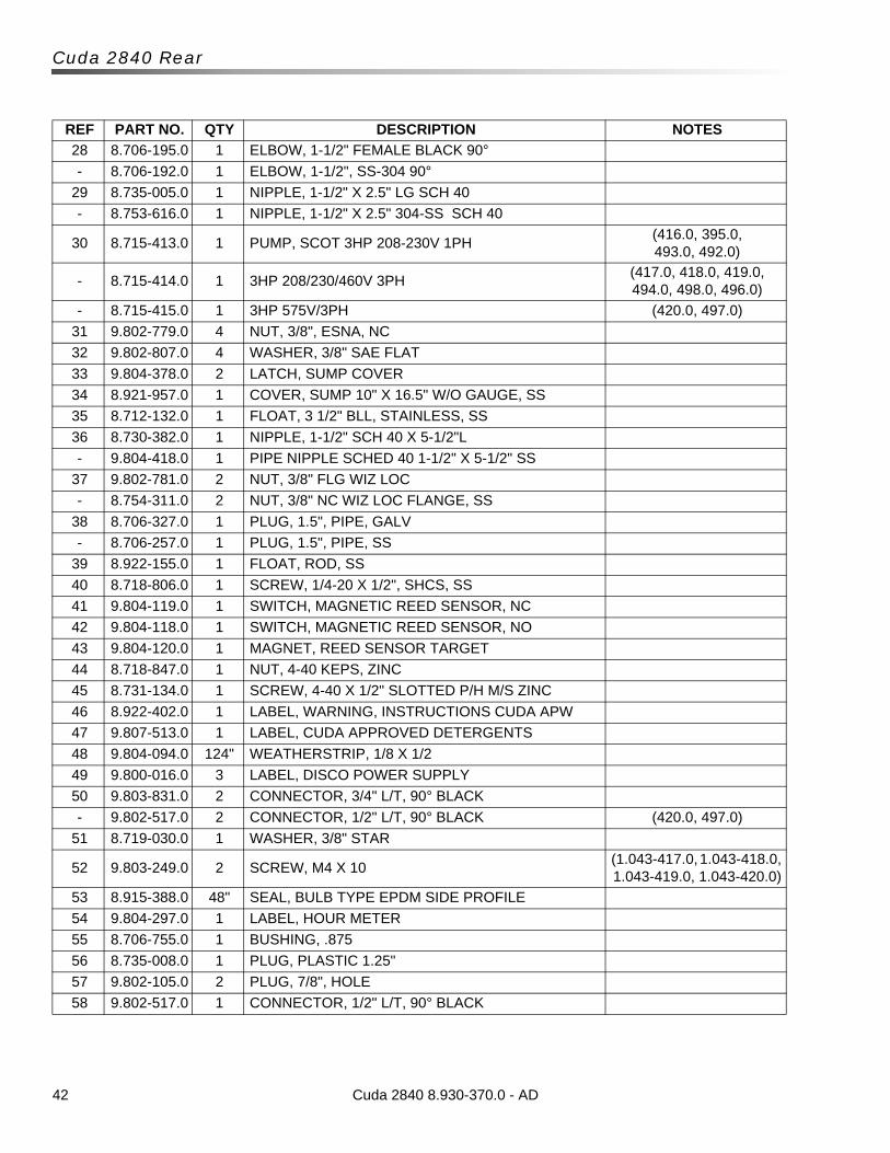
42
Cuda 2840 Rear
REF PART NO. QTY DESCRIPTION NOTES
28 8.706-195.0 1 ELBOW, 1-1/2" FEMALE BLACK 90°
- 8.706-192.0 1 ELBOW, 1-1/2", SS-304 90°
29 8.735-005.0 1 NIPPLE, 1-1/2" X 2.5" LG SCH 40
- 8.753-616.0 1 NIPPLE, 1-1/2" X 2.5" 304-SS SCH 40
30 8.715-413.0 1 PUMP, SCOT 3HP 208-230V 1PH (416.0, 395.0, 493.0, 492.0)
- 8.715-414.0 1 3HP 208/230/460V 3PH (417.0, 418.0, 419.0, 494.0, 498.0, 496.0)
- 8.715-415.0 1 3HP 575V/3PH (420.0, 497.0)
31 9.802-779.0 4 NUT, 3/8", ESNA, NC
32 9.802-807.0 4 WASHER, 3/8" SAE FLAT
33 9.804-378.0 2 LATCH, SUMP COVER
34 8.921-957.0 1 COVER, SUMP 10" X 16.5" W/O GAUGE, SS
35 8.712-132.0 1 FLOAT, 3 1/2" BLL, STAINLESS, SS
36 8.730-382.0 1 NIPPLE, 1-1/2" SCH 40 X 5-1/2"L
- 9.804-418.0 1 PIPE NIPPLE SCHED 40 1-1/2" X 5-1/2" SS
37 9.802-781.0 2 NUT, 3/8" FLG WIZ LOC
- 8.754-311.0 2 NUT, 3/8" NC WIZ LOC FLANGE, SS
38 8.706-327.0 1 PLUG, 1.5", PIPE, GALV
- 8.706-257.0 1 PLUG, 1.5", PIPE, SS
39 8.922-155.0 1 FLOAT, ROD, SS
40 8.718-806.0 1 SCREW, 1/4-20 X 1/2", SHCS, SS
41 9.804-119.0 1 SWITCH, MAGNETIC REED SENSOR, NC
42 9.804-118.0 1 SWITCH, MAGNETIC REED SENSOR, NO
43 9.804-120.0 1 MAGNET, REED SENSOR TARGET
44 8.718-847.0 1 NUT, 4-40 KEPS, ZINC
45 8.731-134.0 1 SCREW, 4-40 X 1/2" SLOTTED P/H M/S ZINC
46 8.922-402.0 1 LABEL, WARNING, INSTRUCTIONS CUDA APW
47 9.807-513.0 1 LABEL, CUDA APPROVED DETERGENTS
48 9.804-094.0 124" WEATHERSTRIP, 1/8 X 1/2
49 9.800-016.0 3 LABEL, DISCO POWER SUPPLY
50 9.803-831.0 2 CONNECTOR, 3/4" L/T, 90° BLACK
- 9.802-517.0 2 CONNECTOR, 1/2" L/T, 90° BLACK (420.0, 497.0)
51 8.719-030.0 1 WASHER, 3/8" STAR
52 9.803-249.0 2 SCREW, M4 X 10 (1.043-417.0, 1.043-418.0, 1.043-419.0, 1.043-420.0)
53 8.915-388.0 48" SEAL, BULB TYPE EPDM SIDE PROFILE
54 9.804-297.0 1 LABEL, HOUR METER
55 8.706-755.0 1 BUSHING, .875
56 8.735-008.0 1 PLUG, PLASTIC 1.25"
57 9.802-105.0 2 PLUG, 7/8", HOLE
58 9.802-517.0 1 CONNECTOR, 1/2" L/T, 90° BLACK
Cuda 2840 8.930-370.0 - AD
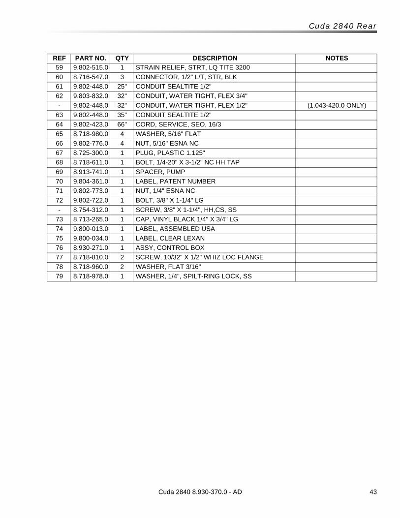
43Cuda 2840 8.930-370.0 - AD
Cuda 2840 Rear
REF PART NO. QTY DESCRIPTION NOTES
59 9.802-515.0 1 STRAIN RELIEF, STRT, LQ TITE 3200
60 8.716-547.0 3 CONNECTOR, 1/2" L/T, STR, BLK
61 9.802-448.0 25" CONDUIT SEALTITE 1/2"
62 9.803-832.0 32" CONDUIT, WATER TIGHT, FLEX 3/4"
- 9.802-448.0 32" CONDUIT, WATER TIGHT, FLEX 1/2" (1.043-420.0 ONLY)
63 9.802-448.0 35" CONDUIT SEALTITE 1/2"
64 9.802-423.0 66" CORD, SERVICE, SEO, 16/3
65 8.718-980.0 4 WASHER, 5/16" FLAT
66 9.802-776.0 4 NUT, 5/16" ESNA NC
67 8.725-300.0 1 PLUG, PLASTIC 1.125"
68 8.718-611.0 1 BOLT, 1/4-20" X 3-1/2" NC HH TAP
69 8.913-741.0 1 SPACER, PUMP
70 9.804-361.0 1 LABEL, PATENT NUMBER
71 9.802-773.0 1 NUT, 1/4" ESNA NC
72 9.802-722.0 1 BOLT, 3/8" X 1-1/4" LG
- 8.754-312.0 1 SCREW, 3/8" X 1-1/4", HH,CS, SS
73 8.713-265.0 1 CAP, VINYL BLACK 1/4" X 3/4" LG
74 9.800-013.0 1 LABEL, ASSEMBLED USA
75 9.800-034.0 1 LABEL, CLEAR LEXAN
76 8.930-271.0 1 ASSY, CONTROL BOX
77 8.718-810.0 2 SCREW, 10/32" X 1/2" WHIZ LOC FLANGE
78 8.718-960.0 2 WASHER, FLAT 3/16"
79 8.718-978.0 1 WASHER, 1/4", SPILT-RING LOCK, SS
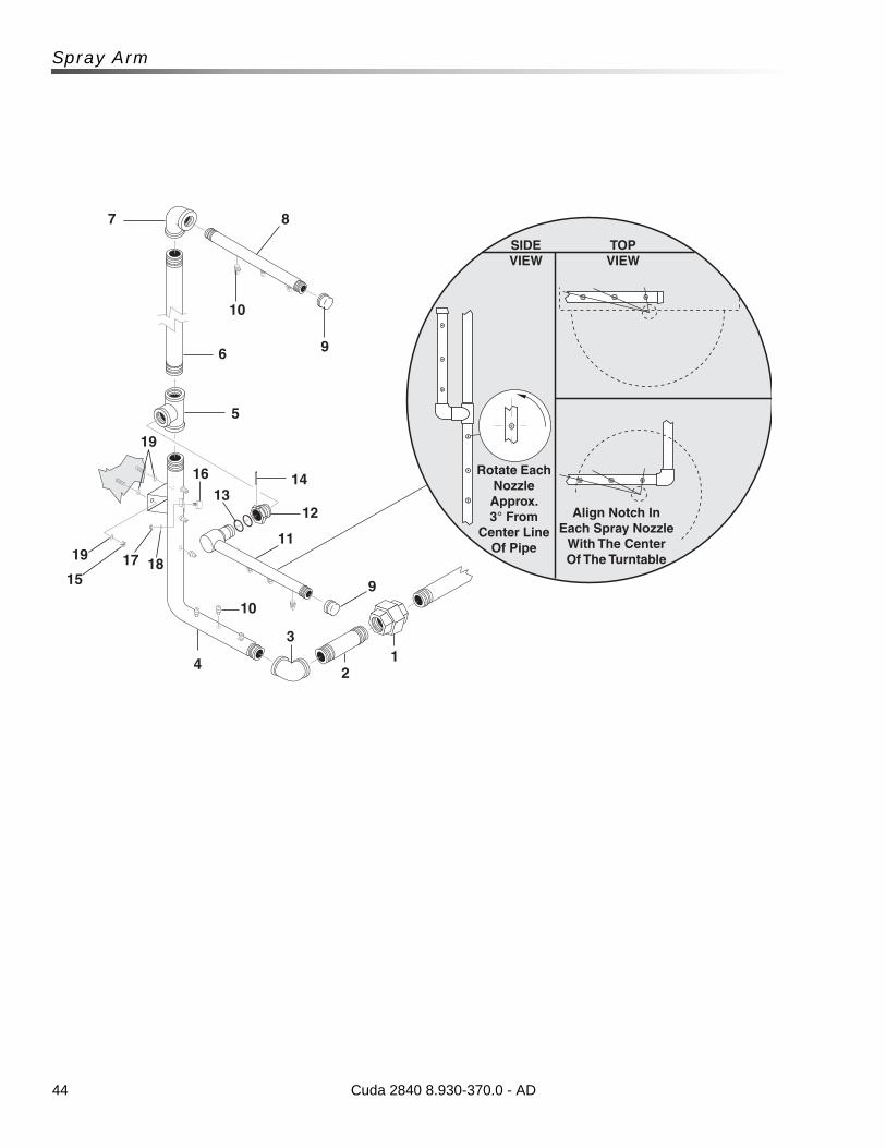
44
Spray Arm
7 8
10
96
5
1413
16
12
11
9
10
12
3
4
181715
Rotate Each Nozzle Approx. 3° From
Center Line Of Pipe
Align Notch In Each Spray Nozzle
With The Center Of The Turntable
SIDE VIEW
TOP VIEW
19
19
Cuda 2840 8.930-370.0 - AD
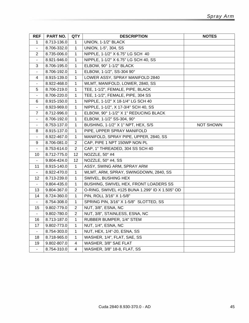
45Cuda 2840 8.930-370.0 - AD
Spray Arm
REF PART NO. QTY DESCRIPTION NOTES
1 8.713-136.0 1 UNION, 1-1/2" BLACK
- 8.706-332.0 1 UNION, 1-5", 304, SS
2 8.735-006.0 1 NIPPLE, 1-1/2" X 6.75" LG SCH 40
- 8.921-946.0 1 NIPPLE, 1-1/2" X 6.75" LG SCH 40, SS
3 8.706-195.0 1 ELBOW, 90° 1-1/2" BLACK
- 8.706-192.0 1 ELBOW, 1-1/2", SS-304 90°
4 8.915-139.0 1 LOWER ASSY, SPRAY MANIFOLD 2840
- 8.922-468.0 1 WLMT, MANIFOLD, LOWER, 2840, SS
5 8.706-219.0 1 TEE, 1-1/2", FEMALE, PIPE, BLACK
- 8.706-220.0 1 TEE, 1-1/2", FEMALE, PIPE, 304 SS
6 8.915-150.0 1 NIPPLE, 1-1/2" X 18-1/4" LG SCH 40
- 8.923-969.0 1 NIPPLE, 1-1/2", X 17-3/4" SCH 40, SS
7 8.712-996.0 1 ELBOW, 90° 1-1/2" X 1" REDUCING BLACK
- 8.706-192.0 1 ELBOW, 1-1/2" SS-304, 90°
- 8.753-137.0 1 BUSHING, 1-1/2" X 1" NPT, HEX, S/S NOT SHOWN
8 8.915-137.0 1 PIPE, UPPER SPRAY MANIFOLD
- 8.922-467.0 1 MANIFOLD, SPRAY PIPE, UPPER, 2840, SS
9 8.706-081.0 2 CAP, PIPE 1 NPT 150WP NON PL
- 8.753-614.0 2 CAP, 1" THREADED, 304 SS SCH 40
10 8.712-775.0 12 NOZZLE, 50° #4
- 9.804-424.0 12 NOZZLE, 50° #4, SS
11 8.915-140.0 1 ASSY, SWING ARM, SPRAY ARM
- 8.922-470.0 1 WLMT, ARM, SPRAY, SWINGDOWN, 2840, SS
12 8.713-239.0 1 SWIVEL, BUSHING HEX
- 9.804-435.0 1 BUSHING, SWIVEL HEX, FRONT LOADERS SS
13 9.804-367.0 2 O-RING, SWIVEL #125 BUNA 1.299" ID X 1.505" OD
14 8.724-360.0 1 PIN, ROLL 3/16" X 1-5/8"
- 8.754-308.0 1 SPRING PIN, 3/16" X 1-5/8" SLOTTED, SS
15 9.802-779.0 2 NUT, 3/8", ESNA, NC
- 9.802-780.0 2 NUT, 3/8", STAINLESS, ESNA, NC
16 8.713-187.0 1 RUBBER BUMPER, 1/4" STEM
17 9.802-773.0 1 NUT, 1/4", ESNA, NC
- 8.754-303.0 1 NUT, HEX, 1/4"-20, ESNA, SS
18 8.718-965.0 1 WASHER, 1/4", FLAT, SAE, SS
19 9.802-807.0 4 WASHER, 3/8" SAE FLAT
- 8.754-310.0 4 WASHER, 3/8" 18-8, FLAT, SS
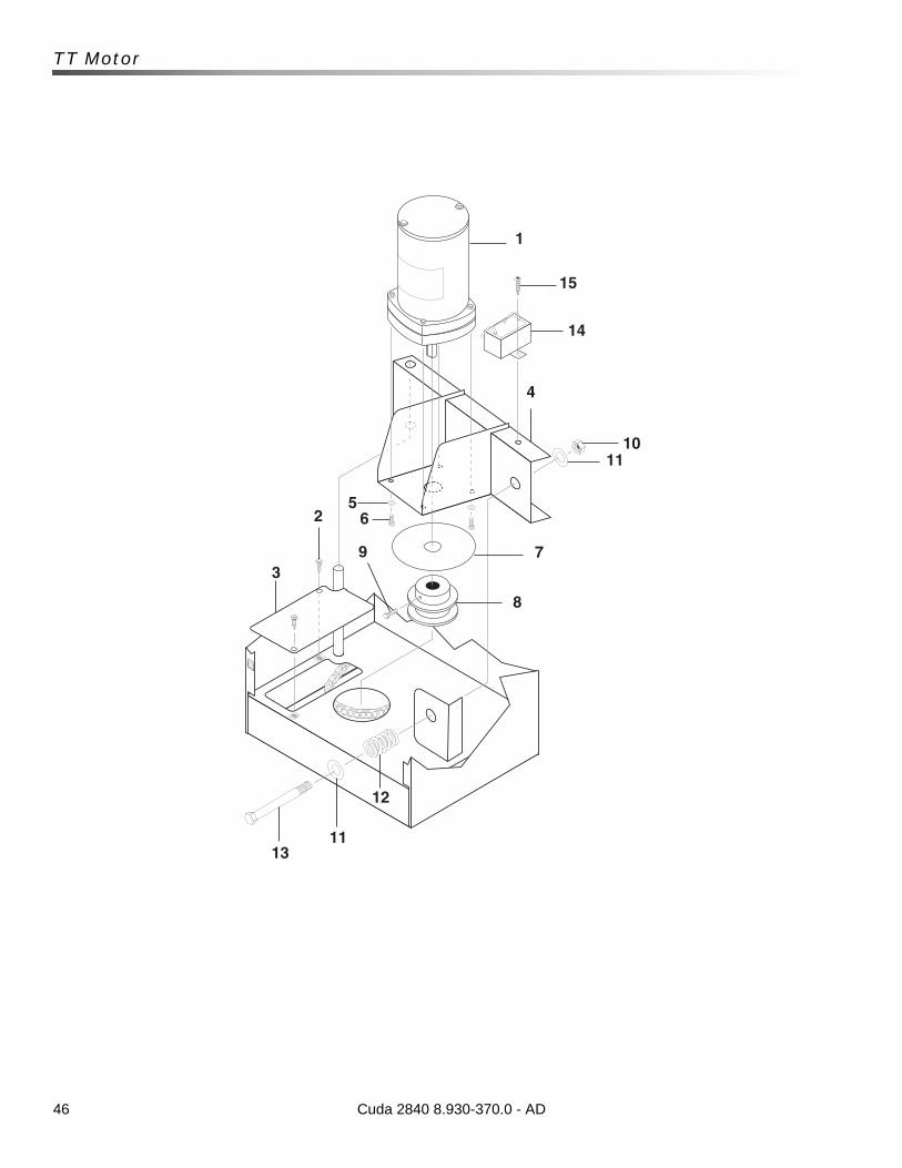
46
TT Motor
1
15
4
1011
7
8
562
3
1311
12
9
14
Cuda 2840 8.930-370.0 - AD
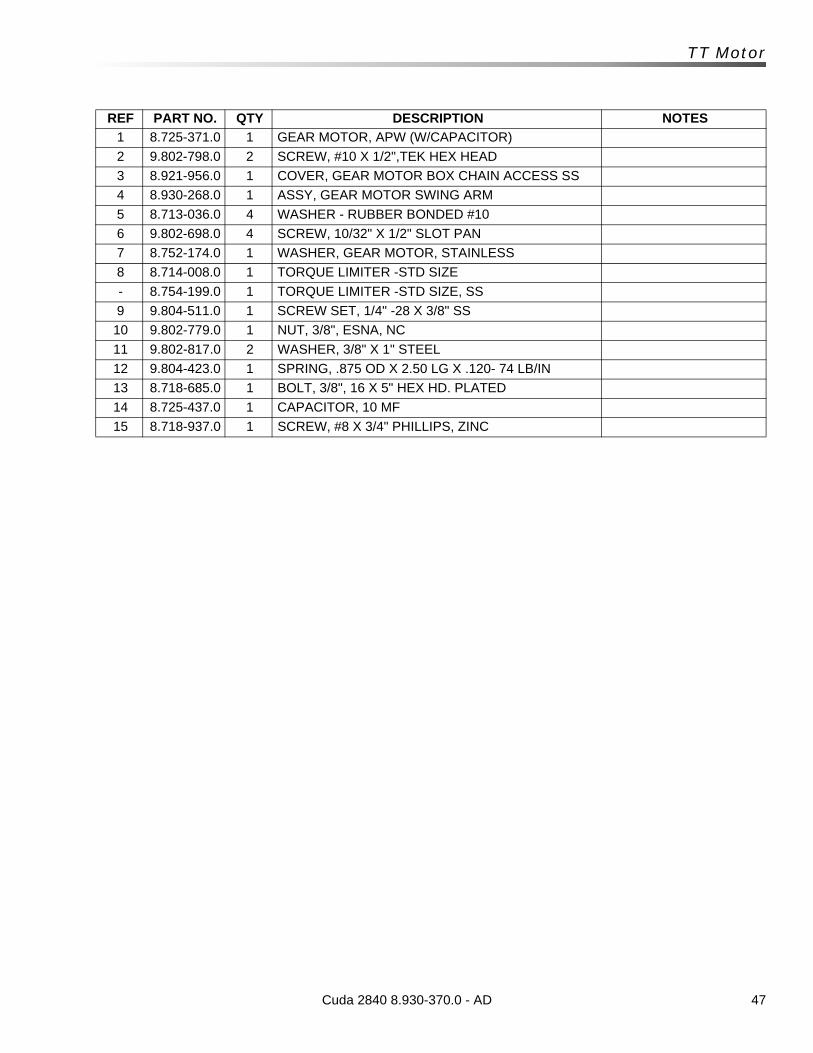
47Cuda 2840 8.930-370.0 - AD
TT Motor
REF PART NO. QTY DESCRIPTION NOTES
1 8.725-371.0 1 GEAR MOTOR, APW (W/CAPACITOR)
2 9.802-798.0 2 SCREW, #10 X 1/2",TEK HEX HEAD
3 8.921-956.0 1 COVER, GEAR MOTOR BOX CHAIN ACCESS SS
4 8.930-268.0 1 ASSY, GEAR MOTOR SWING ARM
5 8.713-036.0 4 WASHER - RUBBER BONDED #10
6 9.802-698.0 4 SCREW, 10/32" X 1/2" SLOT PAN
7 8.752-174.0 1 WASHER, GEAR MOTOR, STAINLESS
8 8.714-008.0 1 TORQUE LIMITER -STD SIZE
- 8.754-199.0 1 TORQUE LIMITER -STD SIZE, SS
9 9.804-511.0 1 SCREW SET, 1/4" -28 X 3/8" SS
10 9.802-779.0 1 NUT, 3/8", ESNA, NC
11 9.802-817.0 2 WASHER, 3/8" X 1" STEEL
12 9.804-423.0 1 SPRING, .875 OD X 2.50 LG X .120- 74 LB/IN
13 8.718-685.0 1 BOLT, 3/8", 16 X 5" HEX HD. PLATED
14 8.725-437.0 1 CAPACITOR, 10 MF
15 8.718-937.0 1 SCREW, #8 X 3/4" PHILLIPS, ZINC
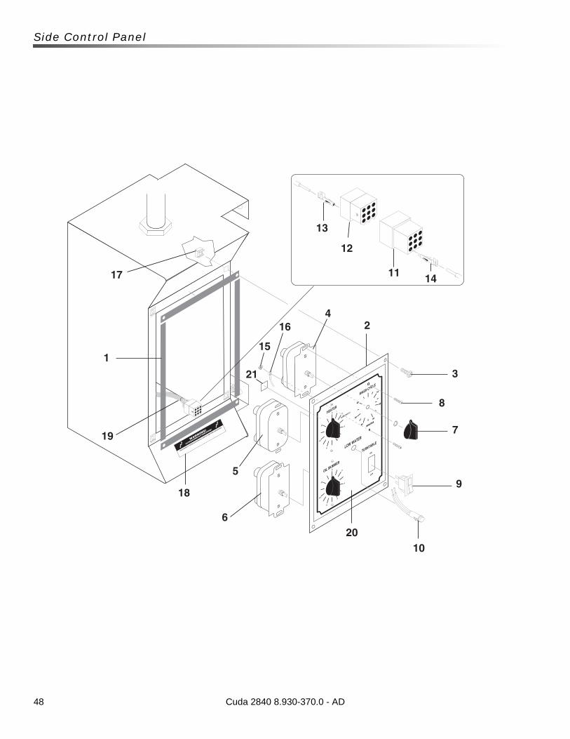
48
Side Control Panel
17
1
19
18
5
6
15
164
2
3
8
7
9
10
1411
12
13
20
21
Cuda 2840 8.930-370.0 - AD
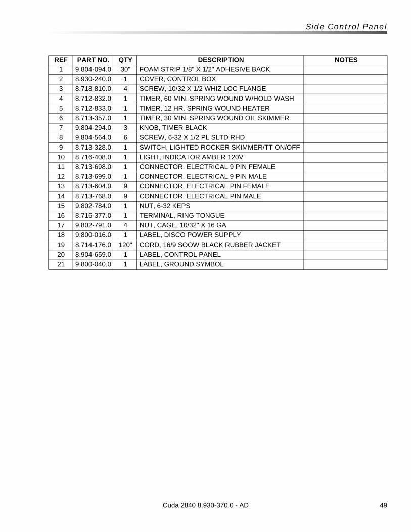
49Cuda 2840 8.930-370.0 - AD
Side Control Panel
REF PART NO. QTY DESCRIPTION NOTES
1 9.804-094.0 30" FOAM STRIP 1/8" X 1/2" ADHESIVE BACK
2 8.930-240.0 1 COVER, CONTROL BOX
3 8.718-810.0 4 SCREW, 10/32 X 1/2 WHIZ LOC FLANGE
4 8.712-832.0 1 TIMER, 60 MIN. SPRING WOUND W/HOLD WASH
5 8.712-833.0 1 TIMER, 12 HR. SPRING WOUND HEATER
6 8.713-357.0 1 TIMER, 30 MIN. SPRING WOUND OIL SKIMMER
7 9.804-294.0 3 KNOB, TIMER BLACK
8 9.804-564.0 6 SCREW, 6-32 X 1/2 PL SLTD RHD
9 8.713-328.0 1 SWITCH, LIGHTED ROCKER SKIMMER/TT ON/OFF
10 8.716-408.0 1 LIGHT, INDICATOR AMBER 120V
11 8.713-698.0 1 CONNECTOR, ELECTRICAL 9 PIN FEMALE
12 8.713-699.0 1 CONNECTOR, ELECTRICAL 9 PIN MALE
13 8.713-604.0 9 CONNECTOR, ELECTRICAL PIN FEMALE
14 8.713-768.0 9 CONNECTOR, ELECTRICAL PIN MALE
15 9.802-784.0 1 NUT, 6-32 KEPS
16 8.716-377.0 1 TERMINAL, RING TONGUE
17 9.802-791.0 4 NUT, CAGE, 10/32" X 16 GA
18 9.800-016.0 1 LABEL, DISCO POWER SUPPLY
19 8.714-176.0 120" CORD, 16/9 SOOW BLACK RUBBER JACKET
20 8.904-659.0 1 LABEL, CONTROL PANEL
21 9.800-040.0 1 LABEL, GROUND SYMBOL
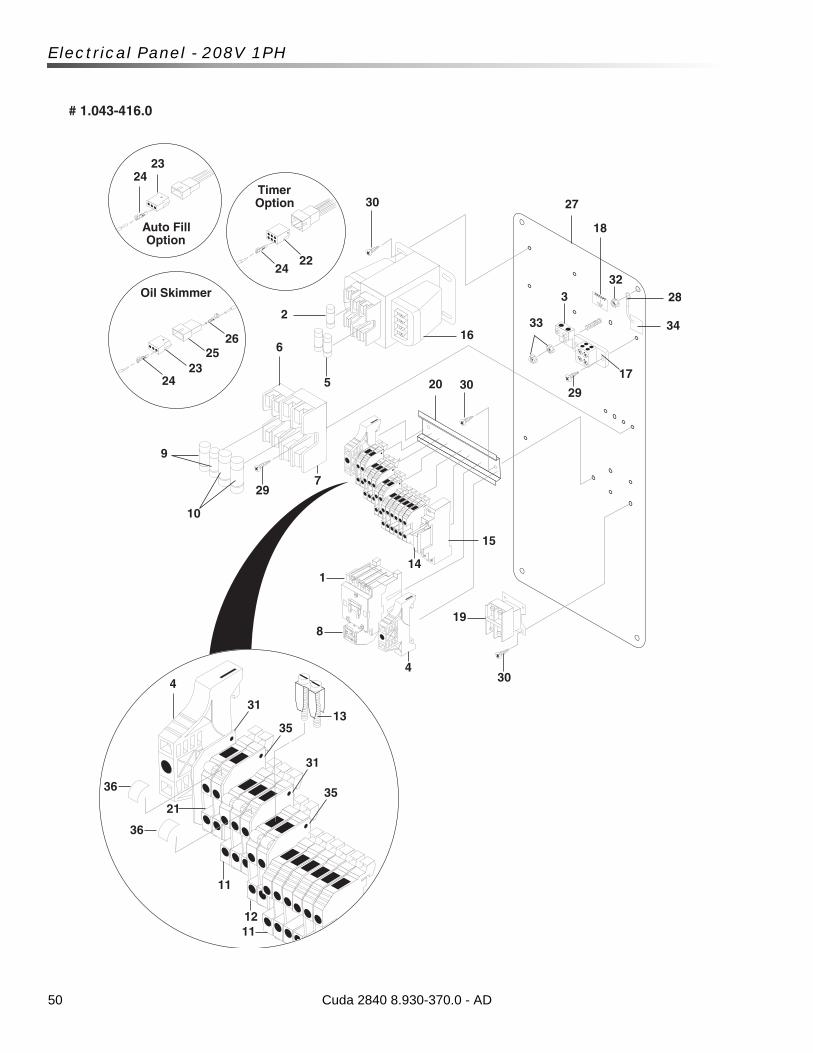
50
Electrical Panel - 208V 1PH
GROUND
1
2324
2324
26
2224
Timer Option
Oil Skimmer
Auto Fill Option
6
2
5
16
30
18
283
17
29
30
25
4
15
14
31
11
1211
21
7
8
4
19
30
29
9
27
32
33
# 1.043-416.0
34
20
36
10
35
31
35
13
36
Cuda 2840 8.930-370.0 - AD

51Cuda 2840 8.930-370.0 - AD
Electrical Panel - 208V 1PH
REF PART NO. QTY DESCRIPTION NOTES
1 8.750-863.0 1 CONTACTOR, IEC, 3 POLE,30 AMPS, NO AUX
2 8.713-078.0 1 FUSE, 2 AMP FNM-2
3 8.713-086.0 1 GROUND, LUG 2 HOLE ALUM
4 9.804-595.0 2 END BRACKET, ENTRELEC, 103-002-26
5 8.713-286.0 2 FUSE, CLASS R 2 AMP FNQ-R-20
6 8.713-290.0 1 FUSE BLOCK (H2PR) 2-POLE
7 8.714-132.0 1 FUSE BLOCK -60A
8 8.750-875.0 1 OVERLOAD 14.5 -18 AMP
9 8.713-293.0 2 FUSE, CLASS R 20 AMP FRN-R-20
10 8.714-451.0 2 FUSE, -35 AMP
11 8.716-398.0 9 TERMINAL BLOCK, BLUE INTRELEC
12 8.716-396.0 2 TERMINAL BLOCK, INTRELEC
13 8.755-016.0 1 TERMINAL BLOCK JUMPER, 2 POLE
14 8.753-367.0 1 RELAY, SPDT
15 8.753-368.0 1 RELAY, BASE
16 8.716-895.0 1 TRANSFORMER, 200/220/440/120V, .200 KVA
17 8.714-164.0 1 TERMINAL BLOCK, 2 POSITION (SURFACE) BL-BL
18 9.800-040.0 1 LABEL, GROUND SYMBOL
19 8.714-290.0 1 CONTACTOR, GEN PURP 2 POLE 230V 30AMP
20 9.802-457.0 7" DIN RAIL, 35 MM
21 8.716-599.0 2 TERMINAL, GROUNDING, GREEN W/YELLOW
22 8.713-697.0 1 CONNECTOR, ELECT 6 PIN MALE
23 8.713-603.0 2 CONNECTOR, ELECT 3 PIN MALE
24 8.713-604.0 12 CONNECTOR, ELECT PIN FEMALE
25 8.713-656.0 1 CONNECTOR, ELECT 3 PIN FEMALE
26 8.713-768.0 3 CONNECTOR, ELECT PIN MALE
27 8.931-186.0 1 PANEL, ELECT, 2840
28 8.716-375.0 2 TERMINAL RING TONGUE RC10-516
29 8.718-937.0 6SCREW, #8 X 3/4" PHILLIPS, ZINC PLATED, HEX TEK
30 9.802-798.0 10 SCREW, #10 X 1/2",TEK HEX HEAD
31 8.716-399.0 2 END COVER, ENTRELEC, GRAY
32 9.802-778.0 1 NUT, WHIZ LOC, 5/16" FLANGE
33 9.802-775.0 2 NUT, 1/4" FLANGE NC
34 8.900-514.0 1 LABEL, 208V, 1 PH
35 8.716-400.0 2 END COVER, ENTRELEC, BLUE
36 9.804-609.0 18 MARKER, BLANK
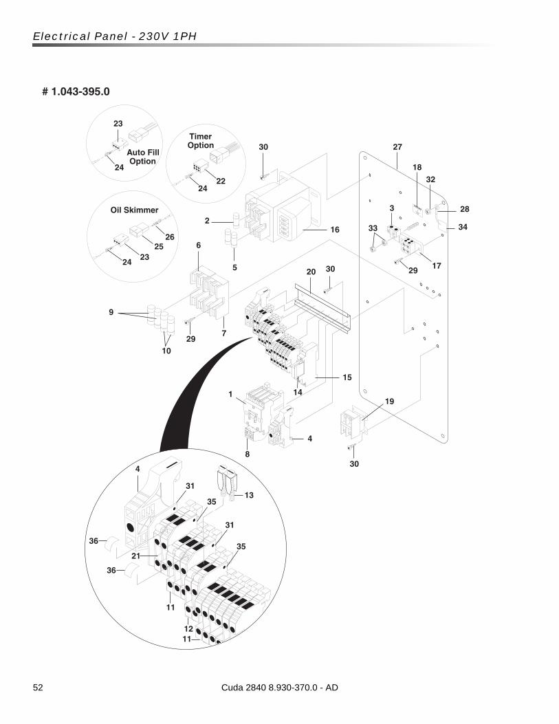
52
Electrical Panel - 230V 1PH
Cuda 2840 8.930-370.0 - AD
GROUND
1
23
24
2324
2526
2224
Timer Option
Oil Skimmer
Auto Fill Option
6
2
5
16
30
18
283
17293020
15
14
7
8
4
19
30
2910
9
27
32
33
# 1.043-395.0
4
31
11
1211
21
36
35
31
35
13
36
34
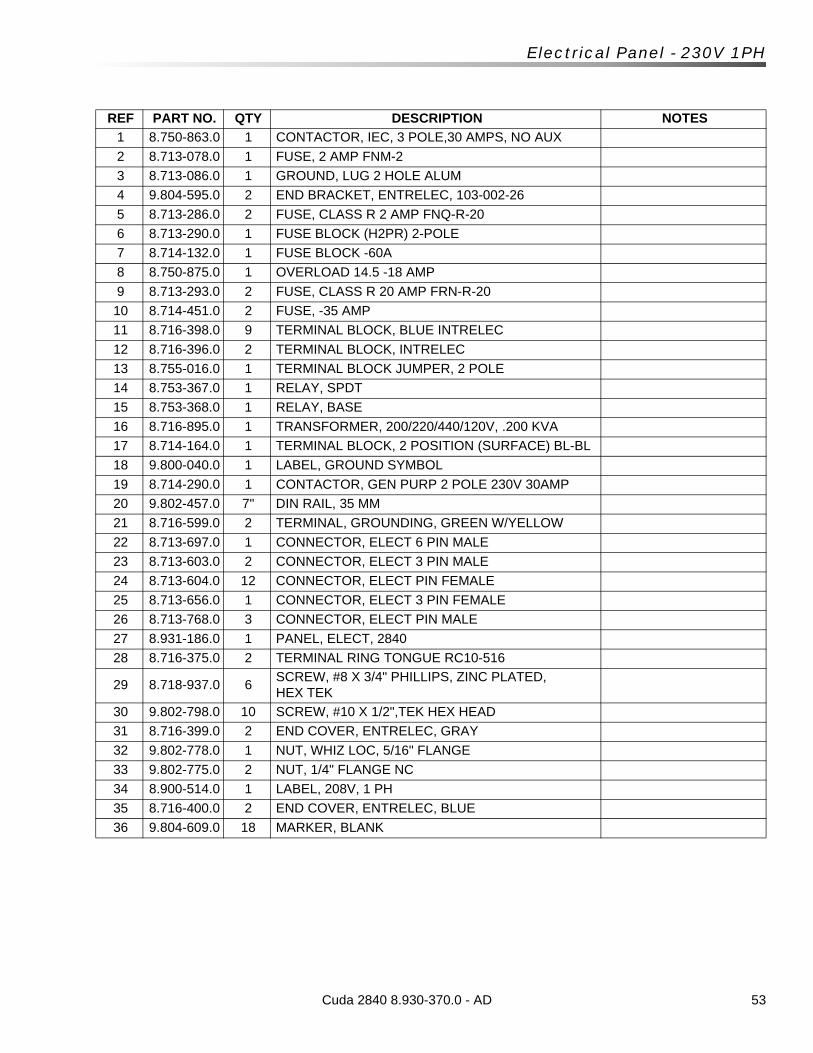
53Cuda 2840 8.930-370.0 - AD
Electrical Panel - 230V 1PH
REF PART NO. QTY DESCRIPTION NOTES
1 8.750-863.0 1 CONTACTOR, IEC, 3 POLE,30 AMPS, NO AUX
2 8.713-078.0 1 FUSE, 2 AMP FNM-2
3 8.713-086.0 1 GROUND, LUG 2 HOLE ALUM
4 9.804-595.0 2 END BRACKET, ENTRELEC, 103-002-26
5 8.713-286.0 2 FUSE, CLASS R 2 AMP FNQ-R-20
6 8.713-290.0 1 FUSE BLOCK (H2PR) 2-POLE
7 8.714-132.0 1 FUSE BLOCK -60A
8 8.750-875.0 1 OVERLOAD 14.5 -18 AMP
9 8.713-293.0 2 FUSE, CLASS R 20 AMP FRN-R-20
10 8.714-451.0 2 FUSE, -35 AMP
11 8.716-398.0 9 TERMINAL BLOCK, BLUE INTRELEC
12 8.716-396.0 2 TERMINAL BLOCK, INTRELEC
13 8.755-016.0 1 TERMINAL BLOCK JUMPER, 2 POLE
14 8.753-367.0 1 RELAY, SPDT
15 8.753-368.0 1 RELAY, BASE
16 8.716-895.0 1 TRANSFORMER, 200/220/440/120V, .200 KVA
17 8.714-164.0 1 TERMINAL BLOCK, 2 POSITION (SURFACE) BL-BL
18 9.800-040.0 1 LABEL, GROUND SYMBOL
19 8.714-290.0 1 CONTACTOR, GEN PURP 2 POLE 230V 30AMP
20 9.802-457.0 7" DIN RAIL, 35 MM
21 8.716-599.0 2 TERMINAL, GROUNDING, GREEN W/YELLOW
22 8.713-697.0 1 CONNECTOR, ELECT 6 PIN MALE
23 8.713-603.0 2 CONNECTOR, ELECT 3 PIN MALE
24 8.713-604.0 12 CONNECTOR, ELECT PIN FEMALE
25 8.713-656.0 1 CONNECTOR, ELECT 3 PIN FEMALE
26 8.713-768.0 3 CONNECTOR, ELECT PIN MALE
27 8.931-186.0 1 PANEL, ELECT, 2840
28 8.716-375.0 2 TERMINAL RING TONGUE RC10-516
29 8.718-937.0 6SCREW, #8 X 3/4" PHILLIPS, ZINC PLATED, HEX TEK
30 9.802-798.0 10 SCREW, #10 X 1/2",TEK HEX HEAD
31 8.716-399.0 2 END COVER, ENTRELEC, GRAY
32 9.802-778.0 1 NUT, WHIZ LOC, 5/16" FLANGE
33 9.802-775.0 2 NUT, 1/4" FLANGE NC
34 8.900-514.0 1 LABEL, 208V, 1 PH
35 8.716-400.0 2 END COVER, ENTRELEC, BLUE
36 9.804-609.0 18 MARKER, BLANK
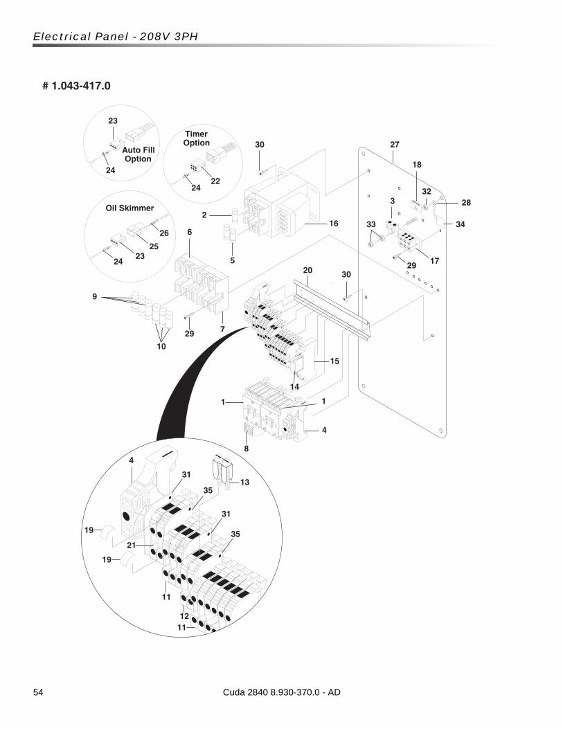
54
Electrical Panel - 208V 3PH
Cuda 2840 8.930-370.0 - AD
GROUND
1
23
24
2324
25
26
2224
Timer Option
Oil Skimmer
Auto Fill Option
6
2
5
16
30
18
283
17293020
15
14
7
8
4
1
29
10
9
27
32
33
# 1.043-417.0
4
31
11
1211
21
19
35
31
35
13
19
34
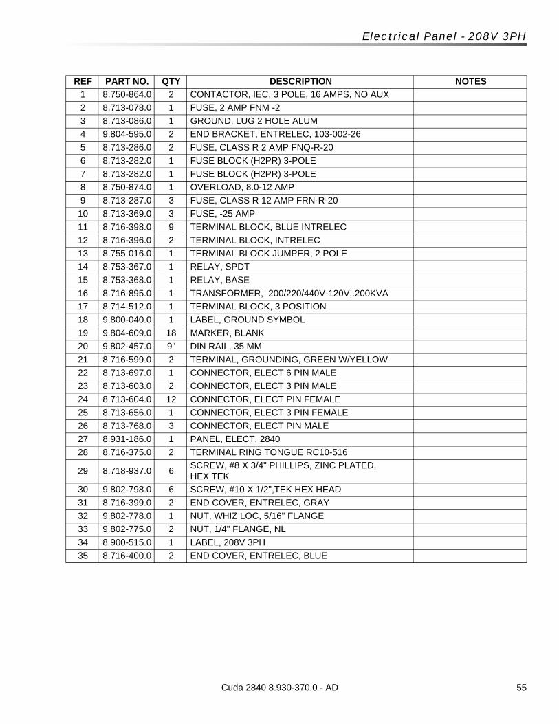
55Cuda 2840 8.930-370.0 - AD
Electrical Panel - 208V 3PH
REF PART NO. QTY DESCRIPTION NOTES
1 8.750-864.0 2 CONTACTOR, IEC, 3 POLE, 16 AMPS, NO AUX
2 8.713-078.0 1 FUSE, 2 AMP FNM -2
3 8.713-086.0 1 GROUND, LUG 2 HOLE ALUM
4 9.804-595.0 2 END BRACKET, ENTRELEC, 103-002-26
5 8.713-286.0 2 FUSE, CLASS R 2 AMP FNQ-R-20
6 8.713-282.0 1 FUSE BLOCK (H2PR) 3-POLE
7 8.713-282.0 1 FUSE BLOCK (H2PR) 3-POLE
8 8.750-874.0 1 OVERLOAD, 8.0-12 AMP
9 8.713-287.0 3 FUSE, CLASS R 12 AMP FRN-R-20
10 8.713-369.0 3 FUSE, -25 AMP
11 8.716-398.0 9 TERMINAL BLOCK, BLUE INTRELEC
12 8.716-396.0 2 TERMINAL BLOCK, INTRELEC
13 8.755-016.0 1 TERMINAL BLOCK JUMPER, 2 POLE
14 8.753-367.0 1 RELAY, SPDT
15 8.753-368.0 1 RELAY, BASE
16 8.716-895.0 1 TRANSFORMER, 200/220/440V-120V,.200KVA
17 8.714-512.0 1 TERMINAL BLOCK, 3 POSITION
18 9.800-040.0 1 LABEL, GROUND SYMBOL
19 9.804-609.0 18 MARKER, BLANK
20 9.802-457.0 9" DIN RAIL, 35 MM
21 8.716-599.0 2 TERMINAL, GROUNDING, GREEN W/YELLOW
22 8.713-697.0 1 CONNECTOR, ELECT 6 PIN MALE
23 8.713-603.0 2 CONNECTOR, ELECT 3 PIN MALE
24 8.713-604.0 12 CONNECTOR, ELECT PIN FEMALE
25 8.713-656.0 1 CONNECTOR, ELECT 3 PIN FEMALE
26 8.713-768.0 3 CONNECTOR, ELECT PIN MALE
27 8.931-186.0 1 PANEL, ELECT, 2840
28 8.716-375.0 2 TERMINAL RING TONGUE RC10-516
29 8.718-937.0 6SCREW, #8 X 3/4" PHILLIPS, ZINC PLATED, HEX TEK
30 9.802-798.0 6 SCREW, #10 X 1/2",TEK HEX HEAD
31 8.716-399.0 2 END COVER, ENTRELEC, GRAY
32 9.802-778.0 1 NUT, WHIZ LOC, 5/16" FLANGE
33 9.802-775.0 2 NUT, 1/4" FLANGE, NL
34 8.900-515.0 1 LABEL, 208V 3PH
35 8.716-400.0 2 END COVER, ENTRELEC, BLUE
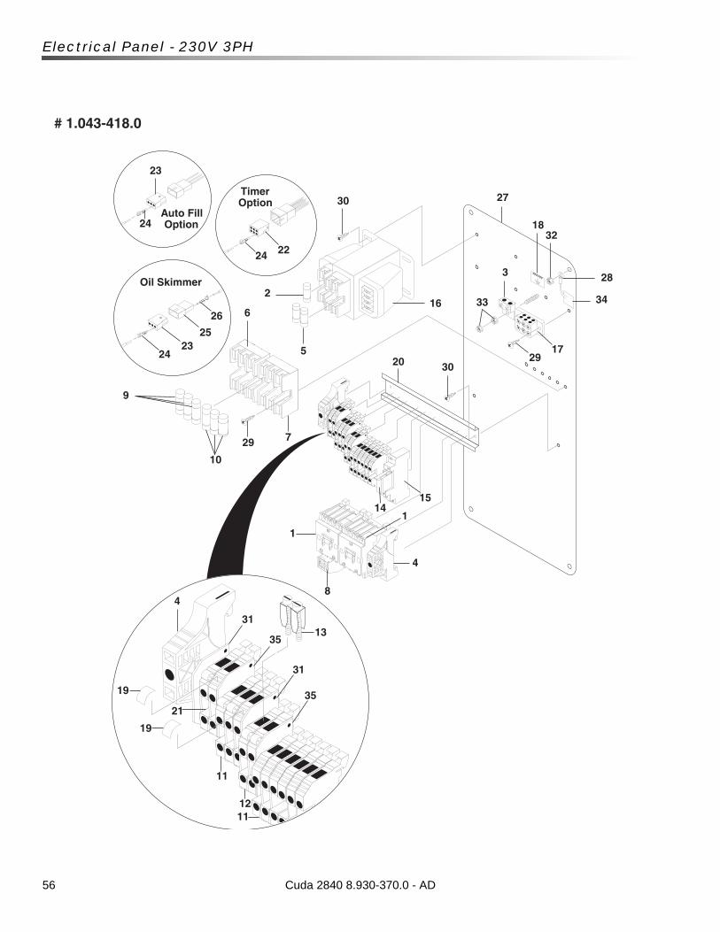
56
Electrical Panel - 230V 3PH
Cuda 2840 8.930-370.0 - AD
GROUND
1
23
24
2324
25
26
2224
Timer Option
Oil Skimmer
Auto Fill Option
6
2
5
16
30
18
283
1729
3020
1514
7
8
4
1
29
10
9
27
32
33
# 1.043-418.0
4
31
11
1211
21
19
35
31
35
13
19
34
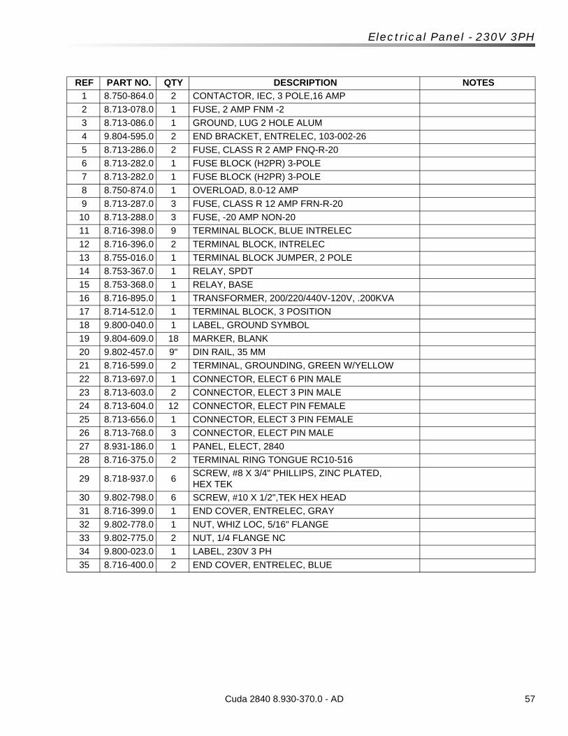
57Cuda 2840 8.930-370.0 - AD
Electrical Panel - 230V 3PH
REF PART NO. QTY DESCRIPTION NOTES
1 8.750-864.0 2 CONTACTOR, IEC, 3 POLE,16 AMP
2 8.713-078.0 1 FUSE, 2 AMP FNM -2
3 8.713-086.0 1 GROUND, LUG 2 HOLE ALUM
4 9.804-595.0 2 END BRACKET, ENTRELEC, 103-002-26
5 8.713-286.0 2 FUSE, CLASS R 2 AMP FNQ-R-20
6 8.713-282.0 1 FUSE BLOCK (H2PR) 3-POLE
7 8.713-282.0 1 FUSE BLOCK (H2PR) 3-POLE
8 8.750-874.0 1 OVERLOAD, 8.0-12 AMP
9 8.713-287.0 3 FUSE, CLASS R 12 AMP FRN-R-20
10 8.713-288.0 3 FUSE, -20 AMP NON-20
11 8.716-398.0 9 TERMINAL BLOCK, BLUE INTRELEC
12 8.716-396.0 2 TERMINAL BLOCK, INTRELEC
13 8.755-016.0 1 TERMINAL BLOCK JUMPER, 2 POLE
14 8.753-367.0 1 RELAY, SPDT
15 8.753-368.0 1 RELAY, BASE
16 8.716-895.0 1 TRANSFORMER, 200/220/440V-120V, .200KVA
17 8.714-512.0 1 TERMINAL BLOCK, 3 POSITION
18 9.800-040.0 1 LABEL, GROUND SYMBOL
19 9.804-609.0 18 MARKER, BLANK
20 9.802-457.0 9" DIN RAIL, 35 MM
21 8.716-599.0 2 TERMINAL, GROUNDING, GREEN W/YELLOW
22 8.713-697.0 1 CONNECTOR, ELECT 6 PIN MALE
23 8.713-603.0 2 CONNECTOR, ELECT 3 PIN MALE
24 8.713-604.0 12 CONNECTOR, ELECT PIN FEMALE
25 8.713-656.0 1 CONNECTOR, ELECT 3 PIN FEMALE
26 8.713-768.0 3 CONNECTOR, ELECT PIN MALE
27 8.931-186.0 1 PANEL, ELECT, 2840
28 8.716-375.0 2 TERMINAL RING TONGUE RC10-516
29 8.718-937.0 6SCREW, #8 X 3/4" PHILLIPS, ZINC PLATED, HEX TEK
30 9.802-798.0 6 SCREW, #10 X 1/2",TEK HEX HEAD
31 8.716-399.0 1 END COVER, ENTRELEC, GRAY
32 9.802-778.0 1 NUT, WHIZ LOC, 5/16" FLANGE
33 9.802-775.0 2 NUT, 1/4 FLANGE NC
34 9.800-023.0 1 LABEL, 230V 3 PH
35 8.716-400.0 2 END COVER, ENTRELEC, BLUE
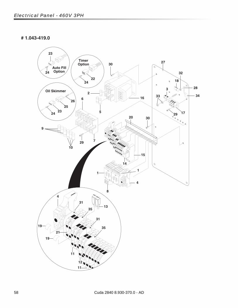
58
Electrical Panel - 460V 3PH
Cuda 2840 8.930-370.0 - AD
GROUND
1
23
24
2324
25
26
2224
Timer Option
Oil Skimmer
Auto Fill Option
6
2
5
16
30
18
283
17293020
15
14
7
8
4
1
2910
9
27
32
33
# 1.043-419.0
4
31
11
12
11
21
19
35
31
35
13
19
34
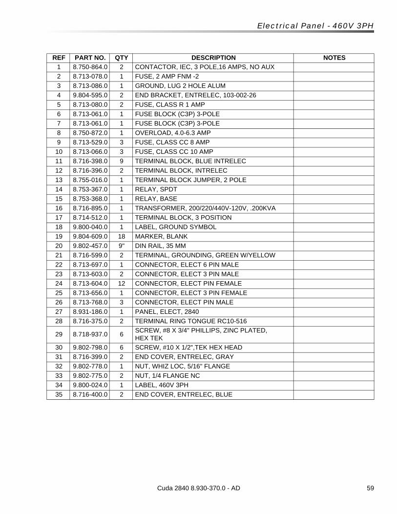
59Cuda 2840 8.930-370.0 - AD
Electrical Panel - 460V 3PH
REF PART NO. QTY DESCRIPTION NOTES
1 8.750-864.0 2 CONTACTOR, IEC, 3 POLE,16 AMPS, NO AUX
2 8.713-078.0 1 FUSE, 2 AMP FNM -2
3 8.713-086.0 1 GROUND, LUG 2 HOLE ALUM
4 9.804-595.0 2 END BRACKET, ENTRELEC, 103-002-26
5 8.713-080.0 2 FUSE, CLASS R 1 AMP
6 8.713-061.0 1 FUSE BLOCK (C3P) 3-POLE
7 8.713-061.0 1 FUSE BLOCK (C3P) 3-POLE
8 8.750-872.0 1 OVERLOAD, 4.0-6.3 AMP
9 8.713-529.0 3 FUSE, CLASS CC 8 AMP
10 8.713-066.0 3 FUSE, CLASS CC 10 AMP
11 8.716-398.0 9 TERMINAL BLOCK, BLUE INTRELEC
12 8.716-396.0 2 TERMINAL BLOCK, INTRELEC
13 8.755-016.0 1 TERMINAL BLOCK JUMPER, 2 POLE
14 8.753-367.0 1 RELAY, SPDT
15 8.753-368.0 1 RELAY, BASE
16 8.716-895.0 1 TRANSFORMER, 200/220/440V-120V, .200KVA
17 8.714-512.0 1 TERMINAL BLOCK, 3 POSITION
18 9.800-040.0 1 LABEL, GROUND SYMBOL
19 9.804-609.0 18 MARKER, BLANK
20 9.802-457.0 9" DIN RAIL, 35 MM
21 8.716-599.0 2 TERMINAL, GROUNDING, GREEN W/YELLOW
22 8.713-697.0 1 CONNECTOR, ELECT 6 PIN MALE
23 8.713-603.0 2 CONNECTOR, ELECT 3 PIN MALE
24 8.713-604.0 12 CONNECTOR, ELECT PIN FEMALE
25 8.713-656.0 1 CONNECTOR, ELECT 3 PIN FEMALE
26 8.713-768.0 3 CONNECTOR, ELECT PIN MALE
27 8.931-186.0 1 PANEL, ELECT, 2840
28 8.716-375.0 2 TERMINAL RING TONGUE RC10-516
29 8.718-937.0 6SCREW, #8 X 3/4" PHILLIPS, ZINC PLATED, HEX TEK
30 9.802-798.0 6 SCREW, #10 X 1/2",TEK HEX HEAD
31 8.716-399.0 2 END COVER, ENTRELEC, GRAY
32 9.802-778.0 1 NUT, WHIZ LOC, 5/16" FLANGE
33 9.802-775.0 2 NUT, 1/4 FLANGE NC
34 9.800-024.0 1 LABEL, 460V 3PH
35 8.716-400.0 2 END COVER, ENTRELEC, BLUE
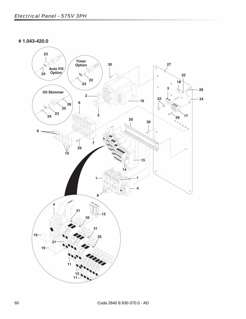
60
Electrical Panel - 575V 3PH
Cuda 2840 8.930-370.0 - AD
GROUND
1
23
24
2324
2526
2224
Timer Option
Oil Skimmer
Auto Fill Option
6
2
5
16
30
18
283
172930
20
15
14
7
8
4
1
2910
9
27
33
32
# 1.043-420.0
4
31
11
1211
21
19
35
31
35
13
19
34
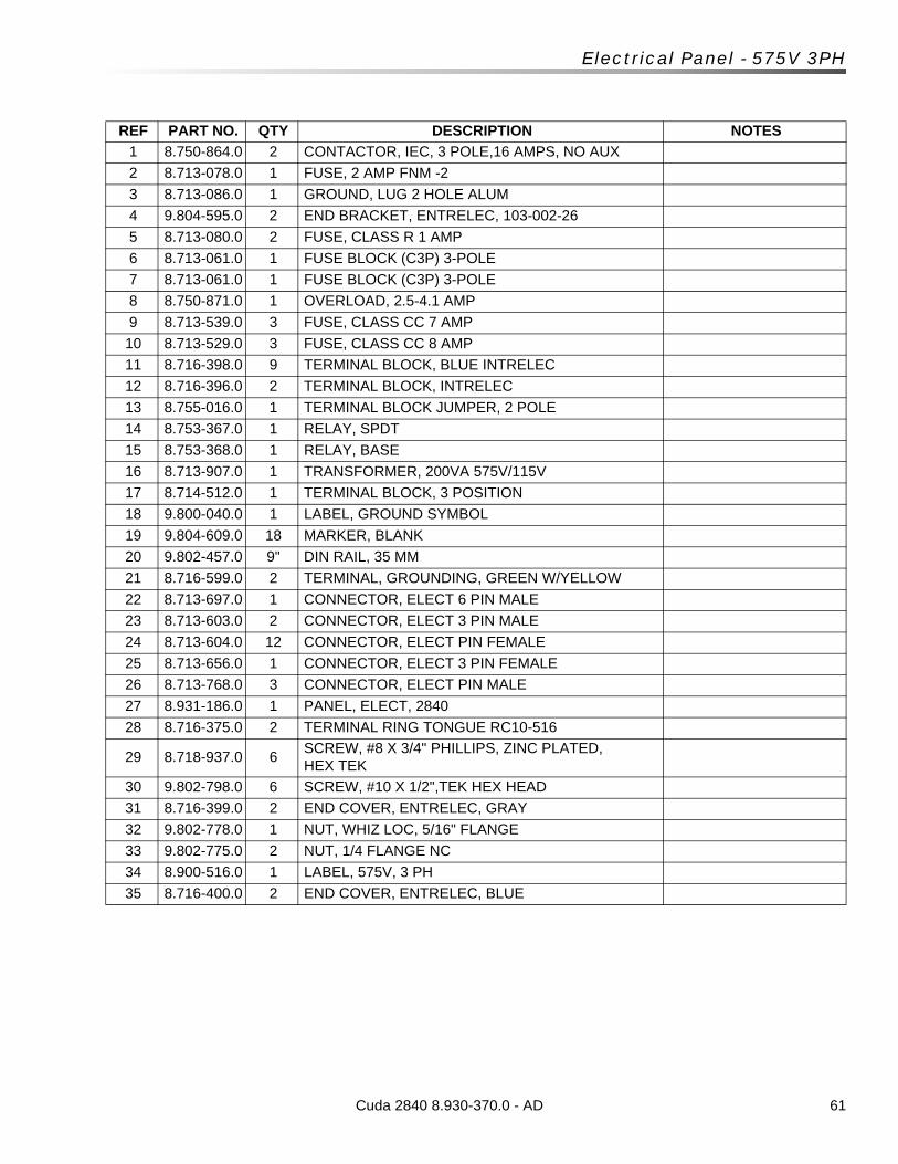
61Cuda 2840 8.930-370.0 - AD
Electrical Panel - 575V 3PH
REF PART NO. QTY DESCRIPTION NOTES
1 8.750-864.0 2 CONTACTOR, IEC, 3 POLE,16 AMPS, NO AUX
2 8.713-078.0 1 FUSE, 2 AMP FNM -2
3 8.713-086.0 1 GROUND, LUG 2 HOLE ALUM
4 9.804-595.0 2 END BRACKET, ENTRELEC, 103-002-26
5 8.713-080.0 2 FUSE, CLASS R 1 AMP
6 8.713-061.0 1 FUSE BLOCK (C3P) 3-POLE
7 8.713-061.0 1 FUSE BLOCK (C3P) 3-POLE
8 8.750-871.0 1 OVERLOAD, 2.5-4.1 AMP
9 8.713-539.0 3 FUSE, CLASS CC 7 AMP
10 8.713-529.0 3 FUSE, CLASS CC 8 AMP
11 8.716-398.0 9 TERMINAL BLOCK, BLUE INTRELEC
12 8.716-396.0 2 TERMINAL BLOCK, INTRELEC
13 8.755-016.0 1 TERMINAL BLOCK JUMPER, 2 POLE
14 8.753-367.0 1 RELAY, SPDT
15 8.753-368.0 1 RELAY, BASE
16 8.713-907.0 1 TRANSFORMER, 200VA 575V/115V
17 8.714-512.0 1 TERMINAL BLOCK, 3 POSITION
18 9.800-040.0 1 LABEL, GROUND SYMBOL
19 9.804-609.0 18 MARKER, BLANK
20 9.802-457.0 9" DIN RAIL, 35 MM
21 8.716-599.0 2 TERMINAL, GROUNDING, GREEN W/YELLOW
22 8.713-697.0 1 CONNECTOR, ELECT 6 PIN MALE
23 8.713-603.0 2 CONNECTOR, ELECT 3 PIN MALE
24 8.713-604.0 12 CONNECTOR, ELECT PIN FEMALE
25 8.713-656.0 1 CONNECTOR, ELECT 3 PIN FEMALE
26 8.713-768.0 3 CONNECTOR, ELECT PIN MALE
27 8.931-186.0 1 PANEL, ELECT, 2840
28 8.716-375.0 2 TERMINAL RING TONGUE RC10-516
29 8.718-937.0 6SCREW, #8 X 3/4" PHILLIPS, ZINC PLATED, HEX TEK
30 9.802-798.0 6 SCREW, #10 X 1/2",TEK HEX HEAD
31 8.716-399.0 2 END COVER, ENTRELEC, GRAY
32 9.802-778.0 1 NUT, WHIZ LOC, 5/16" FLANGE
33 9.802-775.0 2 NUT, 1/4 FLANGE NC
34 8.900-516.0 1 LABEL, 575V, 3 PH
35 8.716-400.0 2 END COVER, ENTRELEC, BLUE
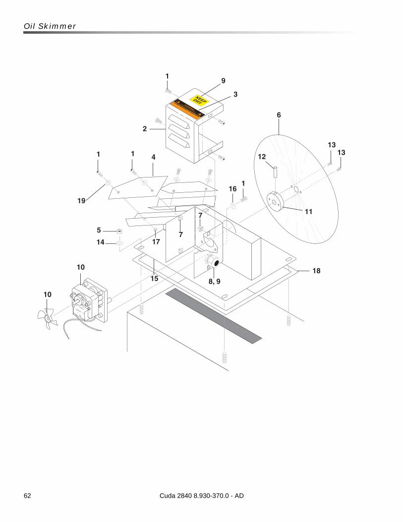
62
Oil Skimmer
KEEPDRY
1
2
1 1 4
6
13
8, 9
7
7
15
10
10
1312
11
116
5
14 17
18
9
3
19
Cuda 2840 8.930-370.0 - AD
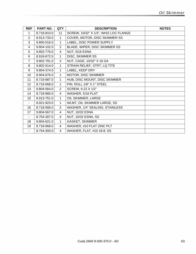
63Cuda 2840 8.930-370.0 - AD
Oil Skimmer
REF PART NO. QTY DESCRIPTION NOTES
1 8.718-810.0 11 SCREW, 10/32" X 1/2", WHIZ LOC FLANGE
2 8.913-733.0 1 COVER, MOTOR, DISC SKIMMER SS
3 9.800-016.0 1 LABEL, DISC POWER SUPPLY
4 9.804-102.0 2 BLADE, WIPER, DISC SKIMMER SS
5 9.802-776.0 4 NUT, 5/16 ESNA
6 8.918-672.0 1 DISC, SKIMMER SS
7 9.802-791.0 4 NUT, CAGE, 10/32" X 16 GA
8 9.802-514.0 1 STRAIN RELIEF, STRT, LQ TITE
9 9.804-374.0 1 LABEL, KEEP DRY
10 8.904-676.0 1 MOTOR, DISC SKIMMER
11 8.719-987.0 1 HUB, DISC MOUNT, DISC SKIMMER
12 8.719-068.0 1 PIN, ROLL 1/8" X 1" STEEL
13 9.804-564.0 2 SCREW, 6-22 X 1/2"
14 8.718-980.0 4 WASHER, 5/16 FLAT
15 8.913-751.0 1 OIL SKIMMER, LARGE
- 8.921-923.0 1 WLMT, OIL SKIMMER LARGE, SS
16 8.718-568.0 3 WASHER, 1/4" SEALING, STAINLESS
17 9.804-567.0 4 NUT, 10/32 ESNA
- 8.754-307.0 4 NUT, 10/32 ESNA, SS
18 9.804-621.0 1 GASKET, SKIMMER
19 8.718-968.0 4 WASHER, #10 FLAT ZINC PLT
- 8.754-300.0 4 WASHER, FLAT, #10 18-8, SS
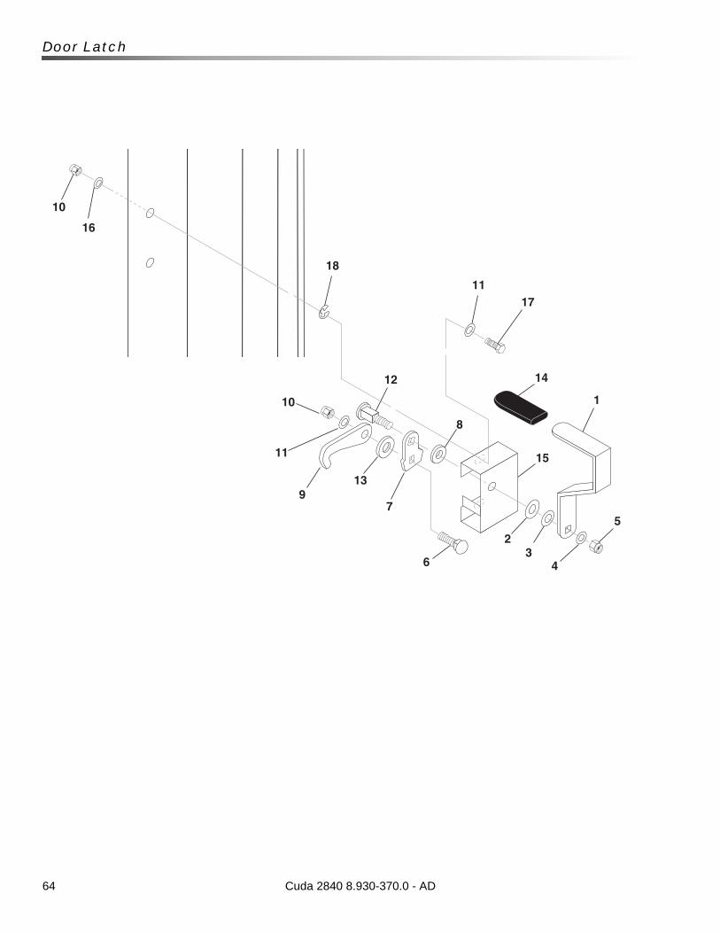
64
Door Latch
1
10
16
11
18
17
5
4
15
12
7
8
6
23
14
10
11
913
Cuda 2840 8.930-370.0 - AD
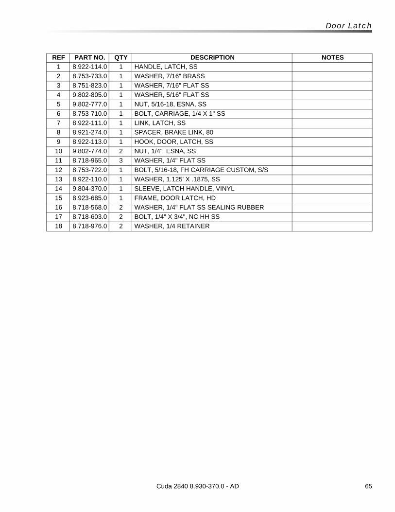
65Cuda 2840 8.930-370.0 - AD
Door Latch
REF PART NO. QTY DESCRIPTION NOTES
1 8.922-114.0 1 HANDLE, LATCH, SS
2 8.753-733.0 1 WASHER, 7/16" BRASS
3 8.751-823.0 1 WASHER, 7/16" FLAT SS
4 9.802-805.0 1 WASHER, 5/16" FLAT SS
5 9.802-777.0 1 NUT, 5/16-18, ESNA, SS
6 8.753-710.0 1 BOLT, CARRIAGE, 1/4 X 1" SS
7 8.922-111.0 1 LINK, LATCH, SS
8 8.921-274.0 1 SPACER, BRAKE LINK, 80
9 8.922-113.0 1 HOOK, DOOR, LATCH, SS
10 9.802-774.0 2 NUT, 1/4" ESNA, SS
11 8.718-965.0 3 WASHER, 1/4" FLAT SS
12 8.753-722.0 1 BOLT, 5/16-18, FH CARRIAGE CUSTOM, S/S
13 8.922-110.0 1 WASHER, 1.125' X .1875, SS
14 9.804-370.0 1 SLEEVE, LATCH HANDLE, VINYL
15 8.923-685.0 1 FRAME, DOOR LATCH, HD
16 8.718-568.0 2 WASHER, 1/4" FLAT SS SEALING RUBBER
17 8.718-603.0 2 BOLT, 1/4" X 3/4", NC HH SS
18 8.718-976.0 2 WASHER, 1/4 RETAINER

8.930-370.0 • Printed in U.S.A.