Embed Size (px)
Citation preview

CULVERT TOP SLAB DESIGN USING OPIS
VOBUG ConferenceAugust 3rd, 2010
Nashville, Tennessee
Robert LeFevre, P.E.Adam Price, P.E.
Tennessee Department of Transportation Structures Division
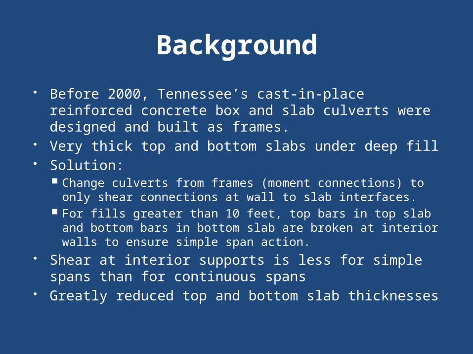
Background Before 2000, Tennessee’s cast-in-place reinforced
concrete box and slab culverts were designed and built as frames.
Very thick top and bottom slabs under deep fill Solution:
Change culverts from frames (moment connections) to only shear connections at wall to slab interfaces.
For fills greater than 10 feet, top bars in top slab and bottom bars in bottom slab are broken at interior walls to ensure simple span action.
Shear at interior supports is less for simple spans than for continuous spans
Greatly reduced top and bottom slab thicknesses

Assignment The current culvert designs are according
to the AASHTO Standard Specifications. In order to receive federal funding, FHWA
requires all culverts to be designed according to the AASHTO LRFD Specifications after October 2010.
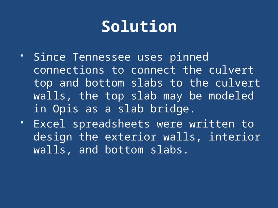
Solution Since Tennessee uses pinned connections
to connect the culvert top and bottom slabs to the culvert walls, the top slab may be modeled in Opis as a slab bridge.
Excel spreadsheets were written to design the exterior walls, interior walls, and bottom slabs.
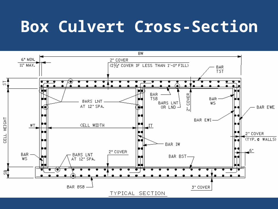
Box Culvert Cross-Section
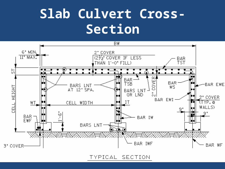
Slab Culvert Cross-Section
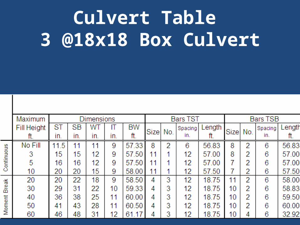
Culvert Table 3 @18x18 Box Culvert
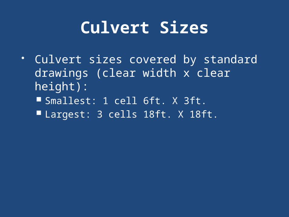
Culvert Sizes Culvert sizes covered by standard
drawings (clear width x clear height): Smallest: 1 cell 6ft. X 3ft. Largest: 3 cells 18ft. X 18ft.
Live Load Distribution Factors (LLDFs)
For a 14’ cell width,no fill,
single cell,LLDF = 0.1240.
AASHTO LRFD 4.6.2.10Equivalent Strip Widths
for Box Culverts
“This Article shall be applied to box culverts with depth of fill less
than 2.0 feet.”
“Design for depths of fill of 2.0 feet or greater are covered in
Article 3.6.1.2.6.”
AASHTO LRFD 4.6.2.10Equivalent Strip Widths for
Box Culverts
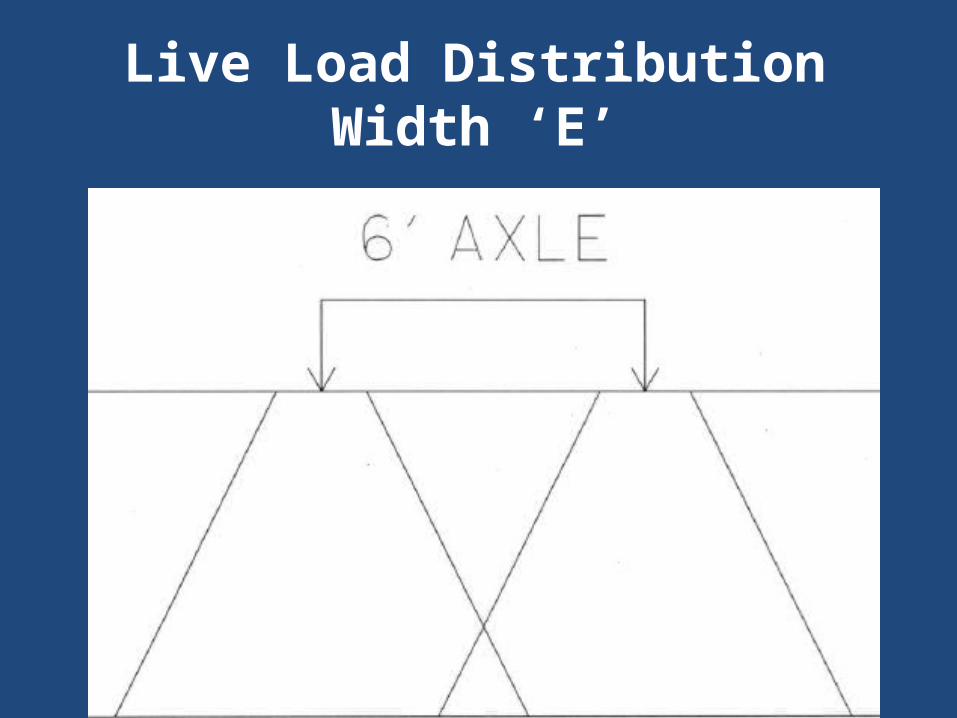
TDOT’s culvert design is based on Case 1: Traffic Travels Parallel to
Span.
The axle load is distributed perpendicularly to the span over a
width ‘E’.
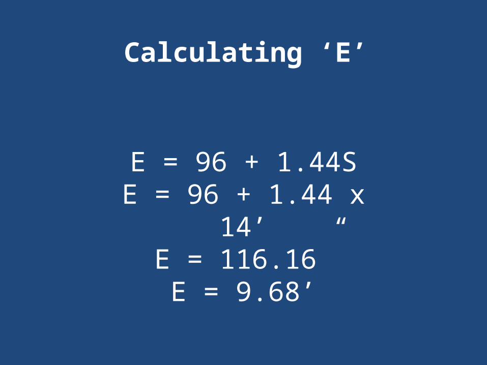
E = 96 + 1.44SE = 96 + 1.44 x 14’
E = 116.16”E = 9.68’
Calculating ‘E’
AASHTO LRFD 4.6.2.10Equivalent Strip Widths
for Box Culverts“When traffic travels primarily
parallel to the span, culverts shall be analyzed for a single loaded
lane with the single lane multiple presence factor.”
From AASHTO LRFD 3.6.1.1.2, the single lane MPF = 1.2
LLDF = (1/E) x MPFLLDF = (1/9.68’) x 1.2LLDF = 0.1240 lanes
Calculating the LLDF
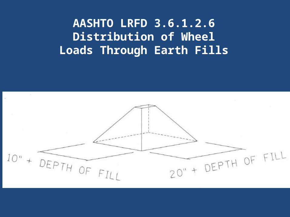
AASHTO LRFD 3.6.1.2.6Distribution of Wheel Loads Through Earth
Fills“…where the depth of fill is 2.0
feet or greater, wheel loads may be considered to be uniformly distributed over a rectangular area with sides equal to the
dimensions of the tire contact area… and increased by…the
depth of the fill...”
AASHTO LRFD 3.6.1.2.5
Tire Contact Area
“The tire contact area...shall be assumed to be a single rectangle whose width is 20.0 inches and whose length is 10.0 inches.”
AASHTO LRFD 3.6.1.2.6Distribution of Wheel Loads
Through Earth Fills
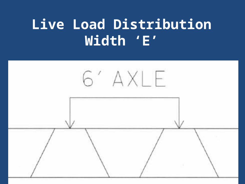
Live Load Distribution Width ‘E’
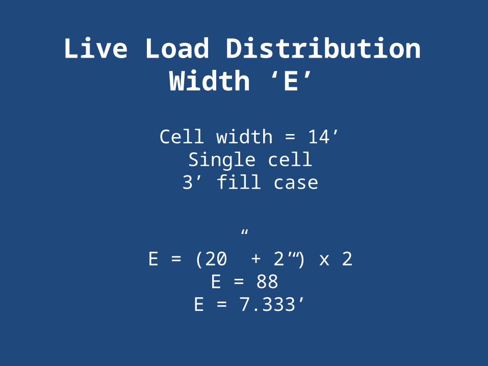
Live Load Distribution Width ‘E’Cell width = 14’
Single cell3’ fill case
E = (20” + 2’) x 2E = 88”
E = 7.333’
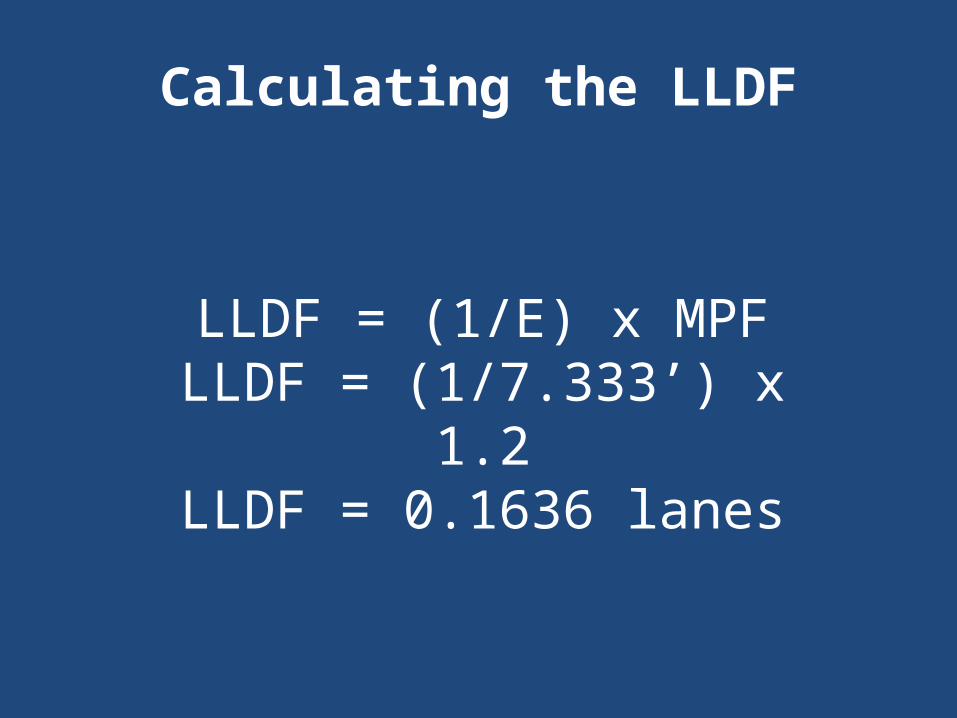
LLDF = (1/E) x MPFLLDF = (1/7.333’) x 1.2
LLDF = 0.1636 lanes
Calculating the LLDF
AASHTO LRFD 3.6.1.2.6Distribution of Wheel
Loads Through Earth Fill
“Where the live load and impact moment in concrete slabs, based on the distribution of the wheel load through earth fills, exceeds the live load and impact moment
calculated according to Article 4.6.2.10, the latter moment shall
be used.”

no fill caseLLDF = 0.1240 lanes
0.1240 < 0.1636Therefore, LLDF =
0.1240
Calculating the LLDF

Live Load Distribution Width ‘E’Cell width = 14’
Single cell5’ fill case
E = (20” + 3’) x 2E = 112”
E = 9.333’

LLDF = (1/E) x MPFLLDF = (1/9.333’) x 1.2
LLDF = 0.1286 lanes
Calculating the LLDF
no fill caseLLDF = 0.1240 lanes
0.1240 < 0.1286Therefore, LLDF =
0.1240
Calculating the LLDF
Live Load Distribution Width ‘E’
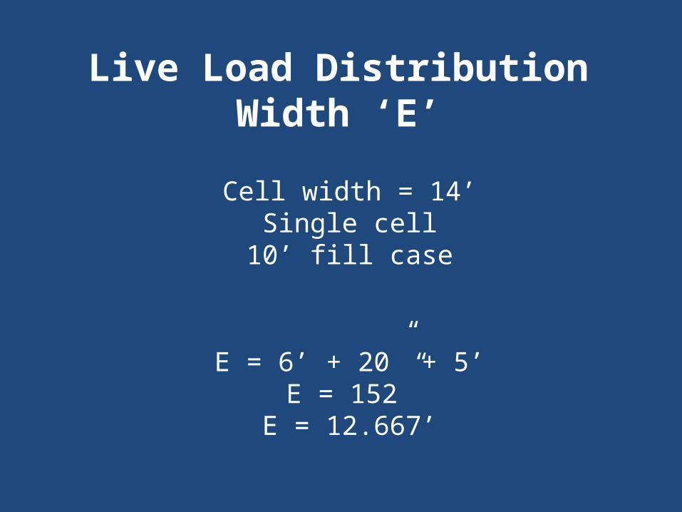
Live Load Distribution Width ‘E’Cell width = 14’
Single cell10’ fill case
E = 6’ + 20” + 5’E = 152”
E = 12.667’

LLDF = (1/E) x MPFLLDF = (1/12.67’) x 1.2
LLDF = 0.0947 lanes
Calculating the LLDF
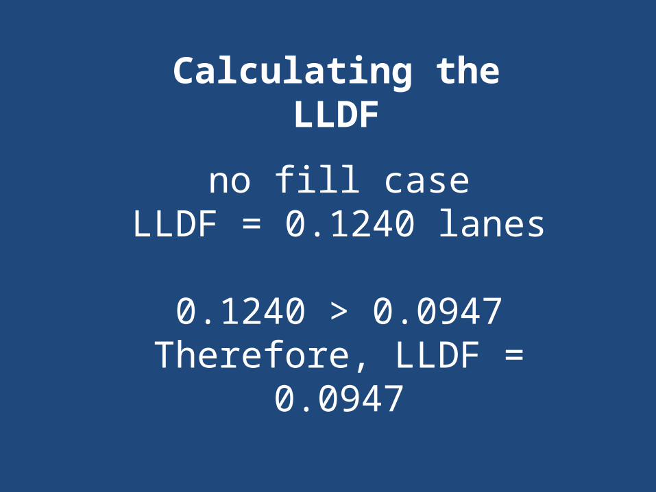
no fill caseLLDF = 0.1240 lanes
0.1240 > 0.0947Therefore, LLDF =
0.0947
Calculating the LLDF
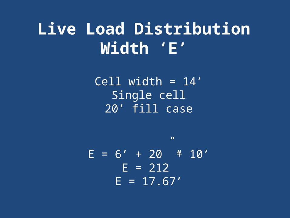
Live Load Distribution Width ‘E’Cell width = 14’
Single cell20’ fill case
E = 6’ + 20” + 10’E = 212”
E = 17.67’
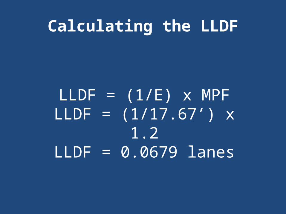
LLDF = (1/E) x MPFLLDF = (1/17.67’) x 1.2
LLDF = 0.0679 lanes
Calculating the LLDF

no fill caseLLDF = 0.1240 lanes
0.1240 > 0.0679Therefore, LLDF =
0.0679
Calculating the LLDF
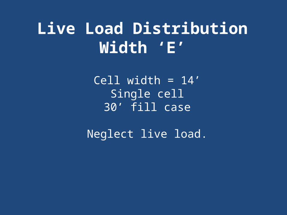
Live Load Distribution Width ‘E’Cell width = 14’
Single cell30’ fill case
Neglect live load.
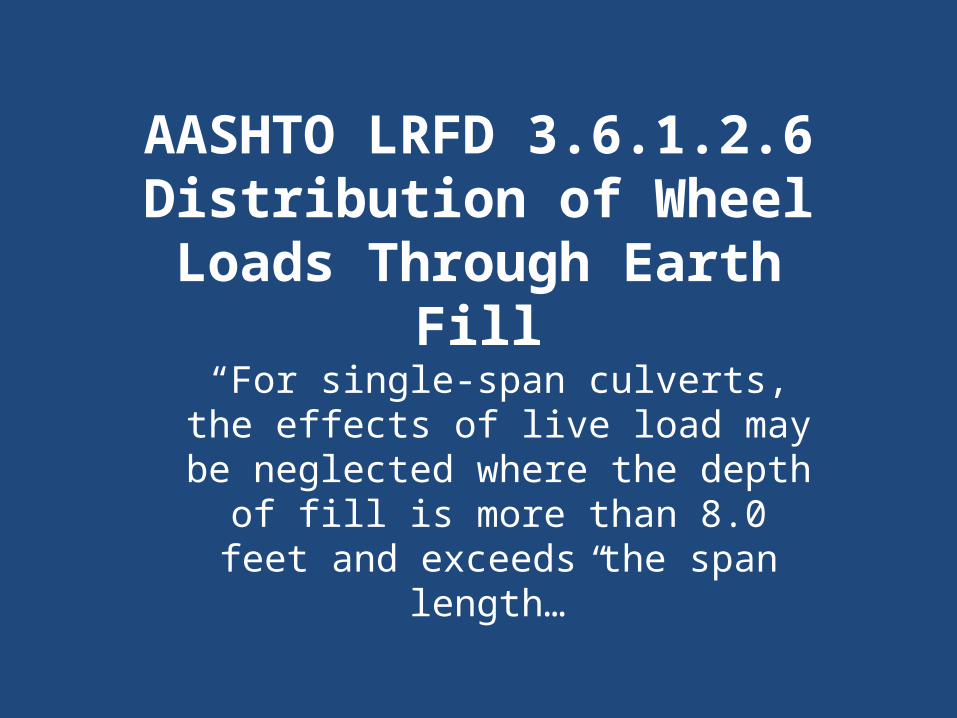
AASHTO LRFD 3.6.1.2.6Distribution of Wheel Loads Through Earth
Fill“For single-span culverts, the
effects of live load may be neglected where the depth of fill
is more than 8.0 feet and exceeds the span length…”
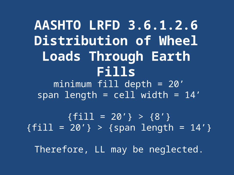
AASHTO LRFD 3.6.1.2.6Distribution of Wheel
Loads Through Earth Fills
minimum fill depth = 20’span length = cell width = 14’
{fill = 20’} > {8’}{fill = 20’} > {span length = 14’}
Therefore, LL may be neglected.
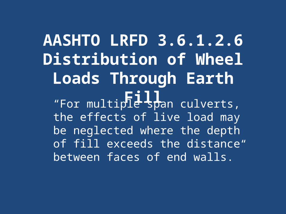
AASHTO LRFD 3.6.1.2.6Distribution of Wheel
Loads Through Earth Fill“For multiple span culverts, the
effects of live load may be neglected where the depth of fill exceeds the distance between
faces of end walls.”
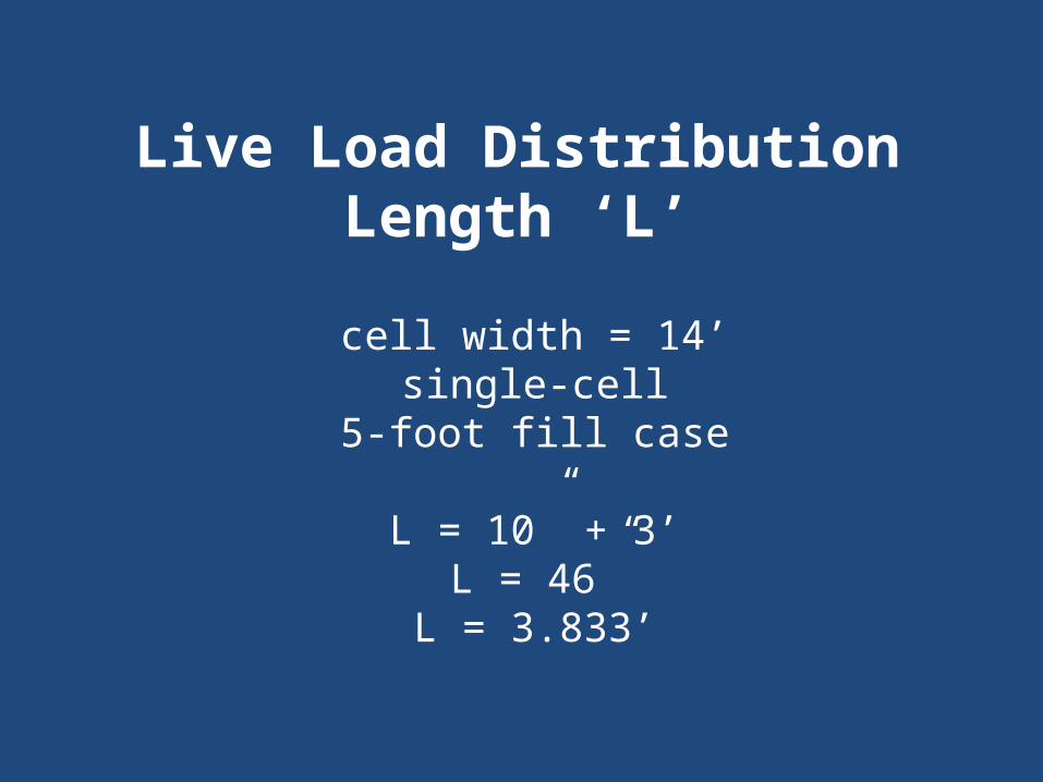
Live Load Distribution Length ‘L’cell width = 14’
single-cell5-foot fill case
L = 10” + 3’L = 46”
L = 3.833’
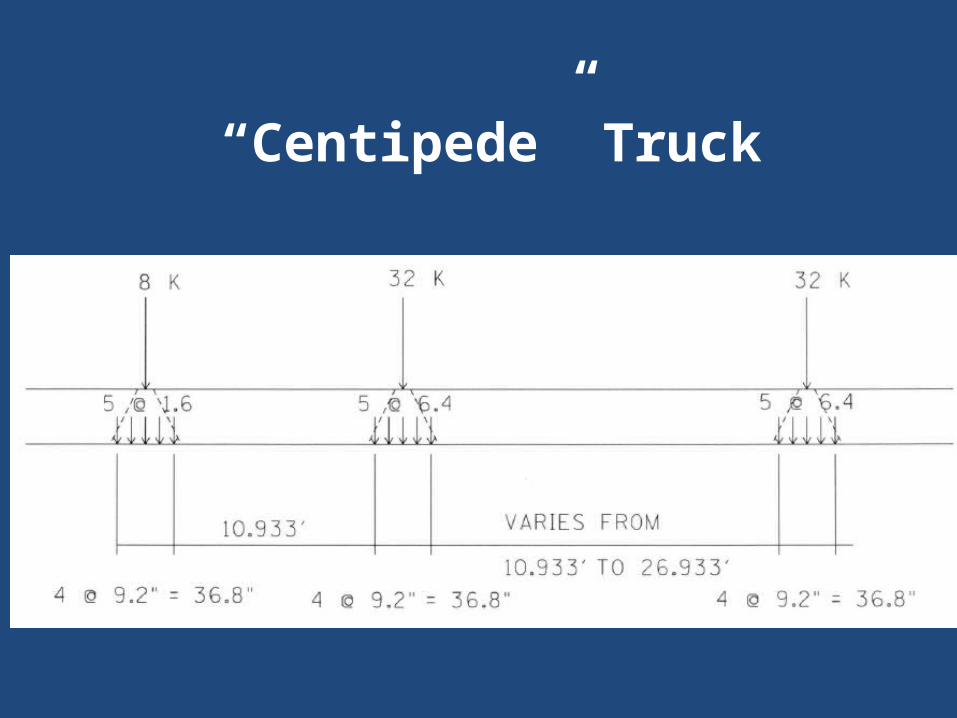
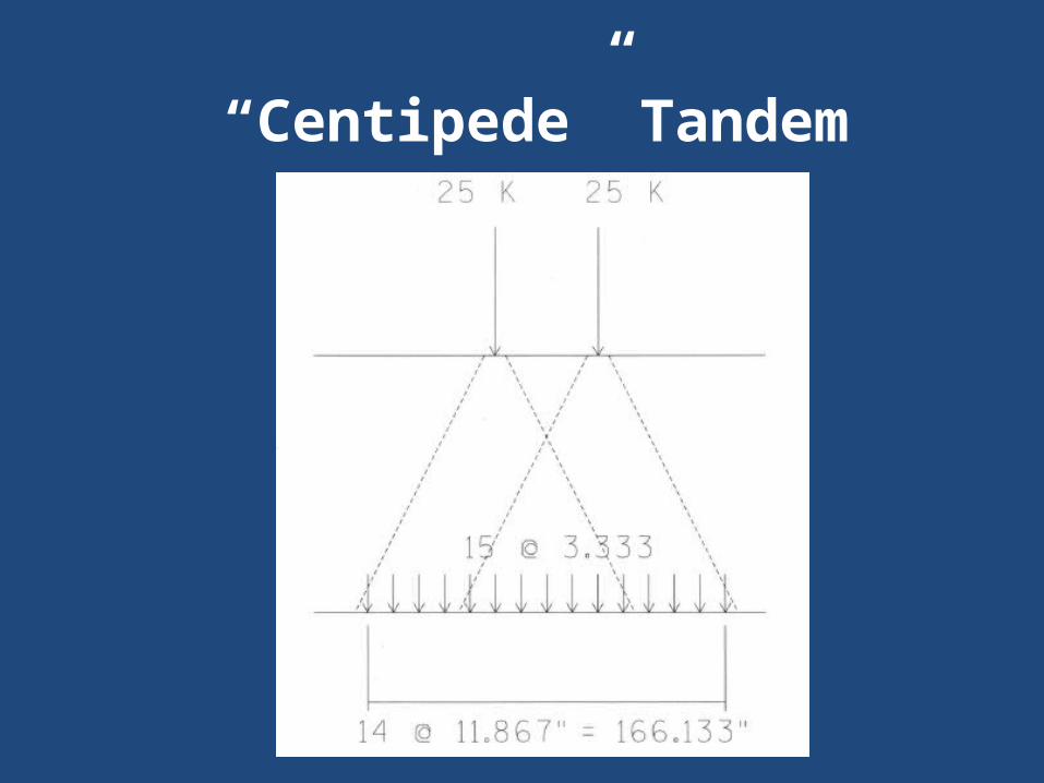
“Centipede” Truck
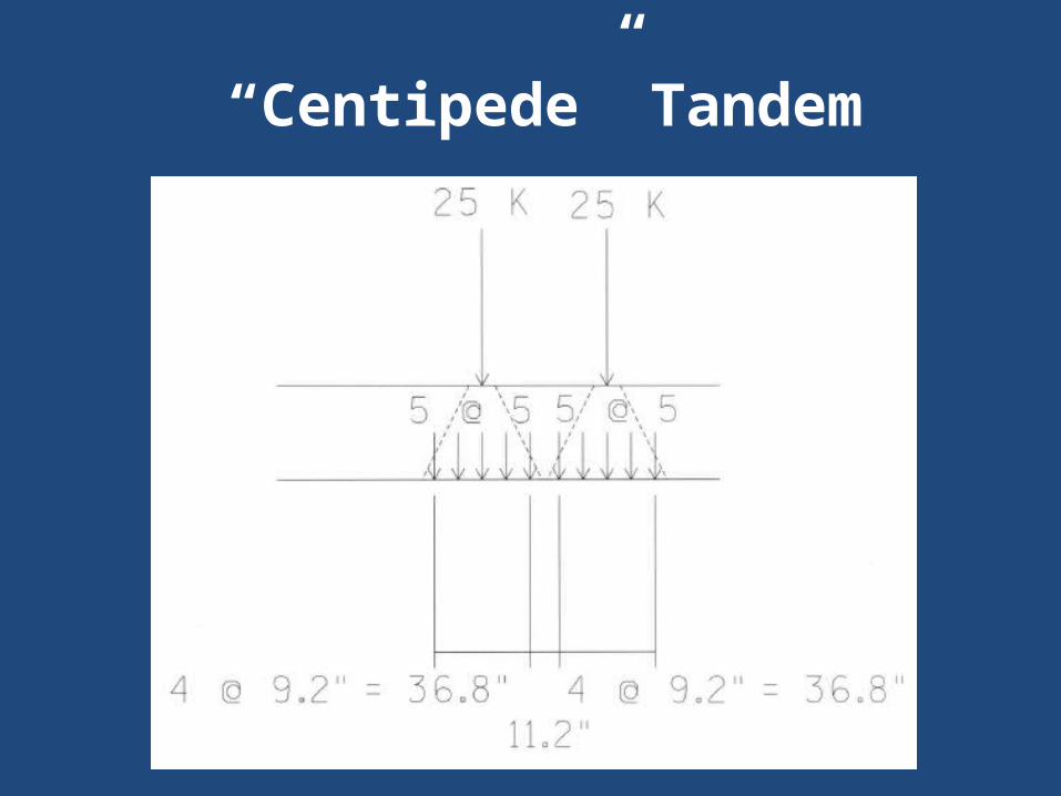
“Centipede” Tandem
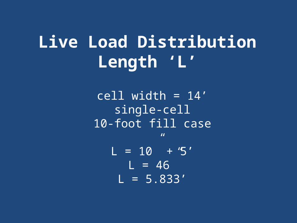
Live Load Distribution Length ‘L’cell width = 14’
single-cell10-foot fill case
L = 10” + 5’L = 46”
L = 5.833’
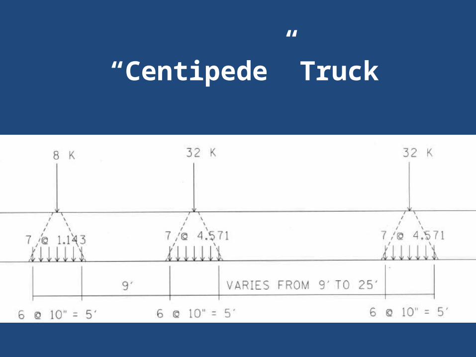
“Centipede” Truck
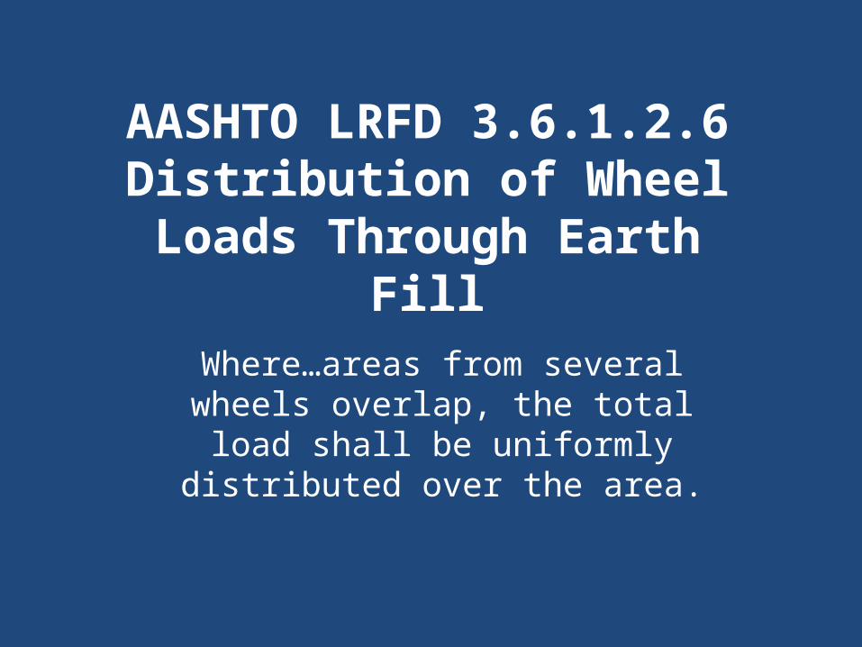
AASHTO LRFD 3.6.1.2.6Distribution of Wheel Loads Through Earth
FillWhere…areas from several
wheels overlap, the total load shall be uniformly distributed
over the area.
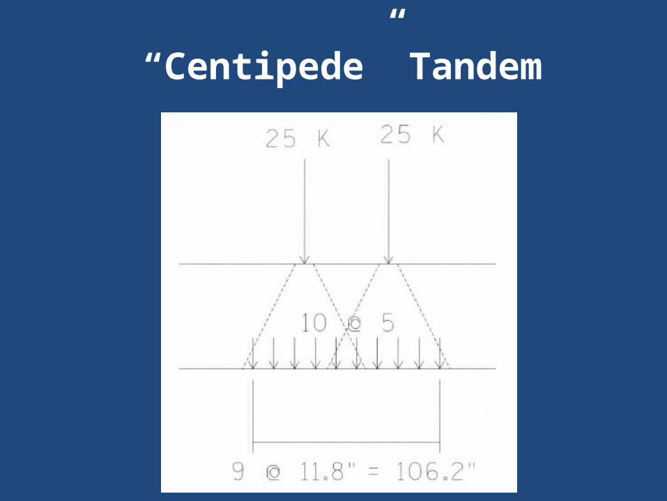
“Centipede” Tandem
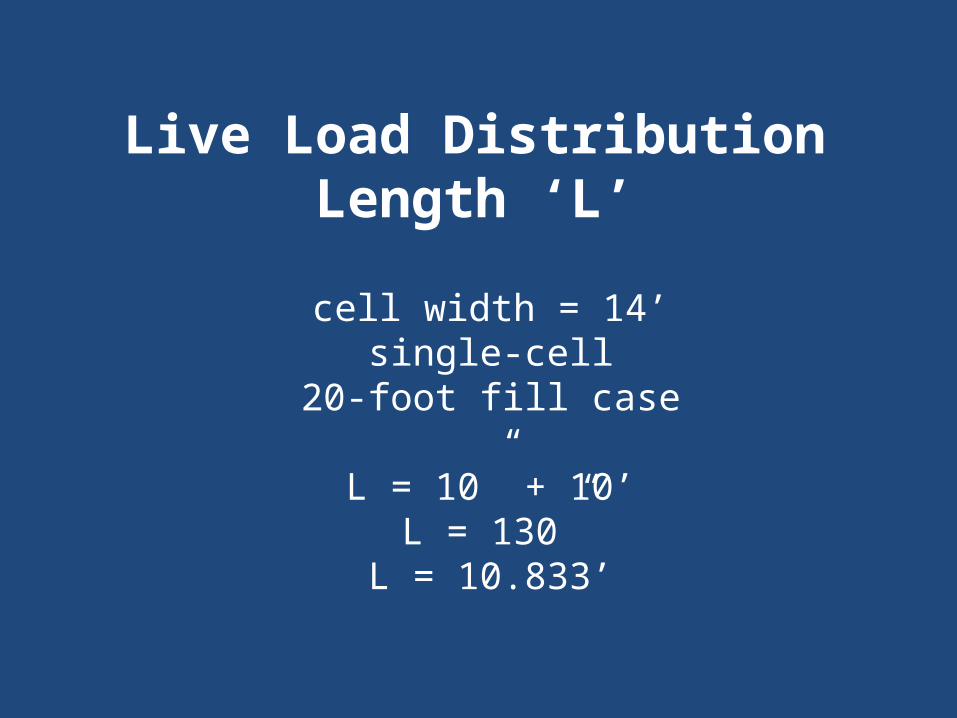
Live Load Distribution Length ‘L’cell width = 14’
single-cell20-foot fill case
L = 10” + 10’L = 130”
L = 10.833’
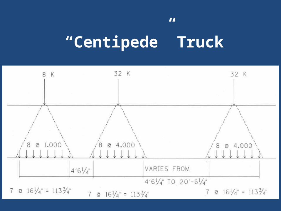
“Centipede” Truck
“Centipede” Tandem

IM = 33% for Limit States other than the Fatigue and Fracture
Limit State.
Dynamic Load Allowance, IM
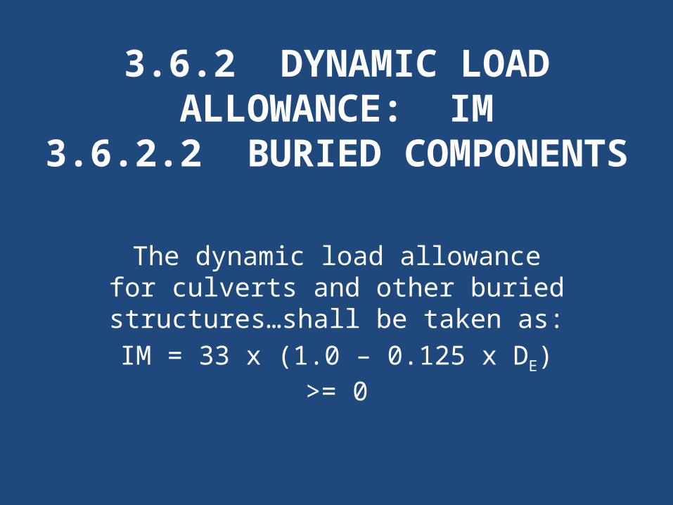
3.6.2 DYNAMIC LOAD ALLOWANCE: IM
3.6.2.2 BURIED COMPONENTS
The dynamic load allowance for culverts and other buried
structures…shall be taken as:IM = 33 x (1.0 – 0.125 x DE) >= 0
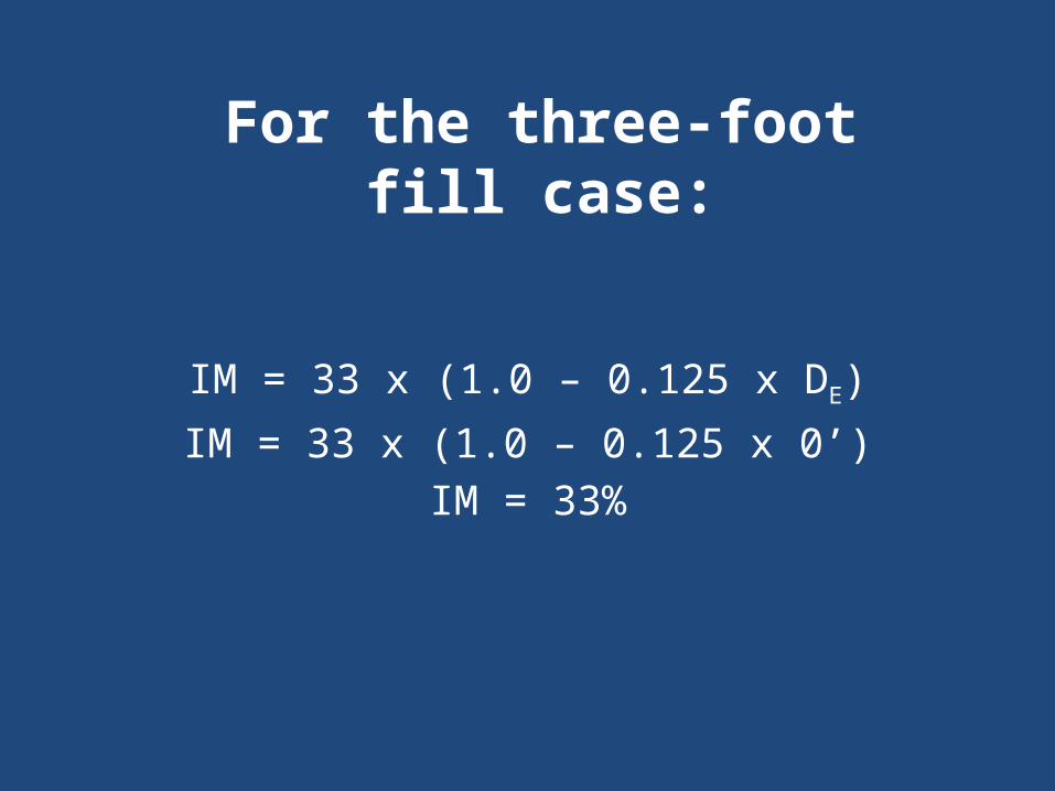
IM = 33 x (1.0 – 0.125 x DE)IM = 33 x (1.0 – 0.125 x 0’)
IM = 33%
For the three-foot fill case:
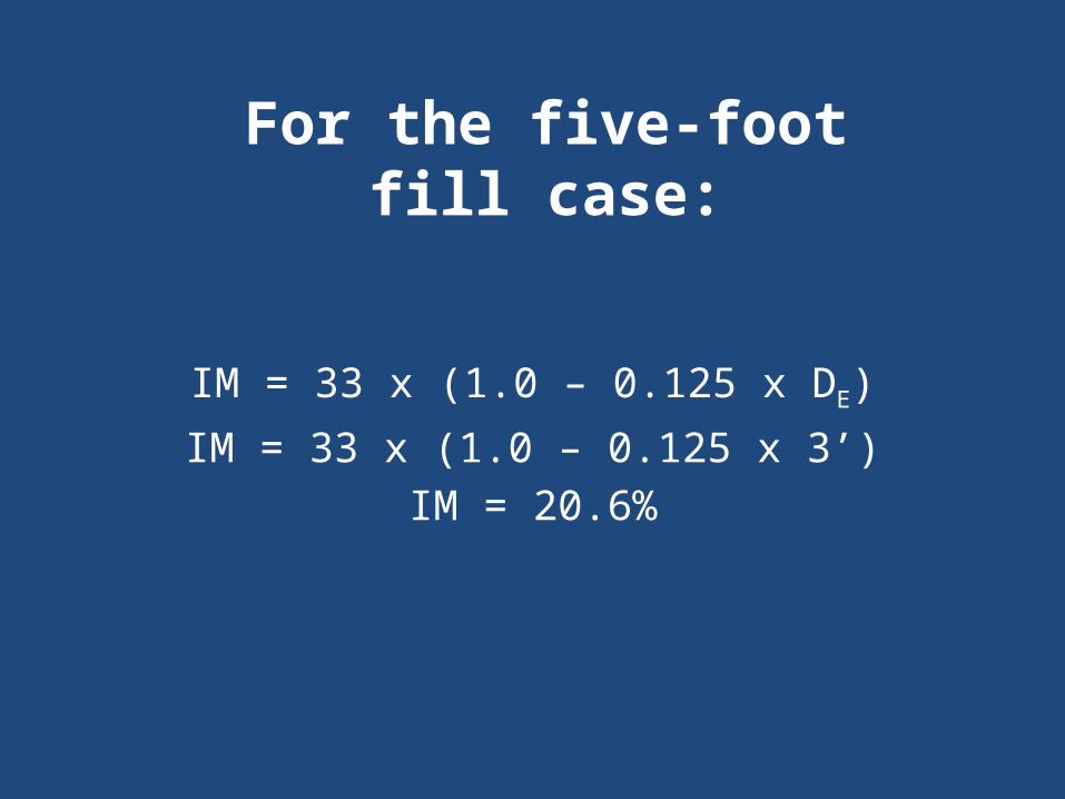
IM = 33 x (1.0 – 0.125 x DE)IM = 33 x (1.0 – 0.125 x 3’)
IM = 20.6%
For the five-foot fill case:

IM = 33 x (1.0 – 0.125 x DE)IM = 33 x (1.0 – 0.125 x 5’)
IM = 12.4%
For the ten-foot fill case:
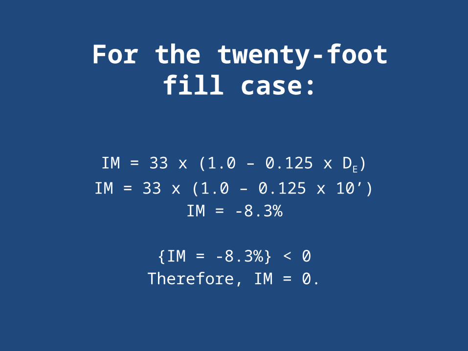
IM = 33 x (1.0 – 0.125 x DE)IM = 33 x (1.0 – 0.125 x 10’)
IM = -8.3%
{IM = -8.3%} < 0Therefore, IM = 0.
For the twenty-foot fill case:
Materials Concrete
28-day Compressive strength: f’c = 3 ksi Reinforcing Steel
ASTM A615 Grade 60 For culverts under less than 1’-0” of fill, bars in
the top mat of the top slab are epoxy coated.
Bar Mark Definitions For reinforced concrete slab bridges, the
reinforcing steel must be defined under the bar mark definitions tab. Name Material (previously defined) Size Type (straight, hooked, etc.) Dimensions
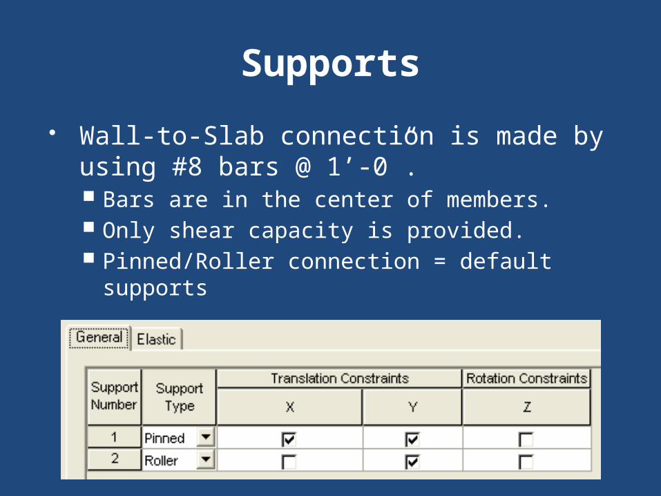
Supports Wall-to-Slab connection is made by using
#8 bars @ 1’-0”. Bars are in the center of members. Only shear capacity is provided. Pinned/Roller connection = default supports
Girder Profile - Section 12 inch strips were used for design. Standard drawing tables are based on per
foot quantities.
Girder Profile - Reinforcement
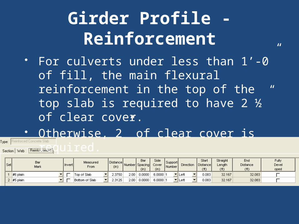
For culverts under less than 1’-0” of fill, the main flexural reinforcement in the top of the top slab is required to have 2 ½” of clear cover.
Otherwise, 2” of clear cover is required.
Girder Profile - Reinforcement
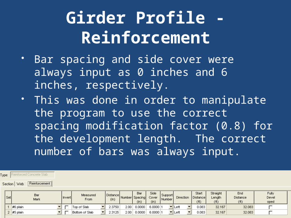
Bar spacing and side cover were always input as 0 inches and 6 inches, respectively.
This was done in order to manipulate the program to use the correct spacing modification factor (0.8) for the development length. The correct number of bars was always input.
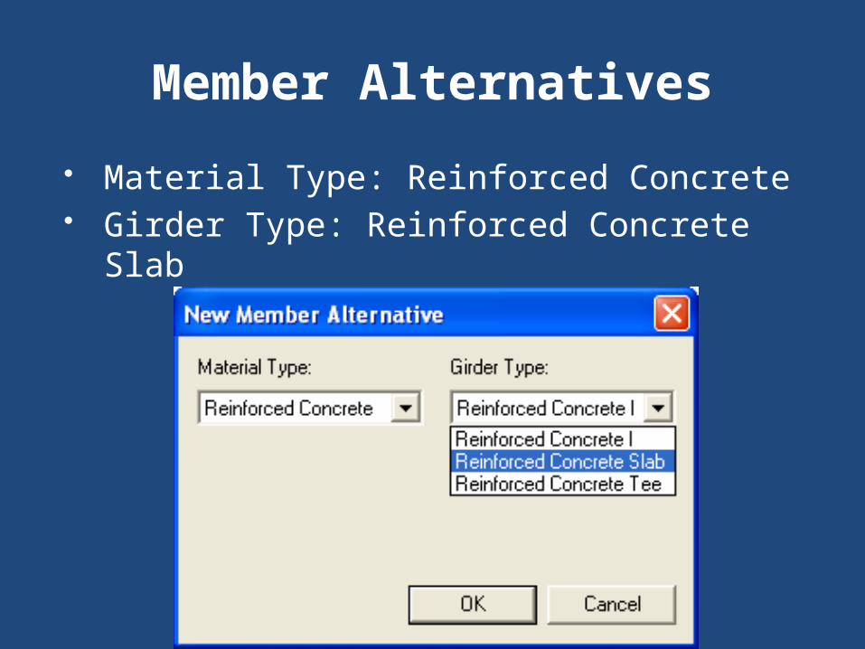
Member Alternatives Material Type: Reinforced Concrete Girder Type: Reinforced Concrete Slab
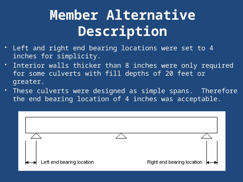
Member Alternative Description
Left and right end bearing locations were set to 4 inches for simplicity.
Interior walls thicker than 8 inches were only required for some culverts with fill depths of 20 feet or greater.
These culverts were designed as simple spans. Therefore the end bearing location of 4 inches was acceptable.
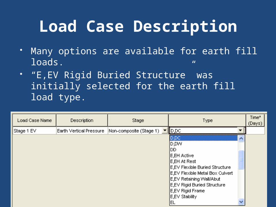
Load Case Description Many options are available for earth fill
loads. “E,EV Rigid Buried Structure” was initially
selected for the earth fill load type.
Load Case Description Problem It was later discovered that none of the
earth fill load types are used by Brass. The earth fill load was not being applied
to the model. “D,DC” was used as the load case type
for the earth fill. The earth fill load as multiplied by
1.3/1.25 to account for the difference in load factors.
Load Case Description Problem Incident 9523 Users should not have the option to input
data not accepted by the engine running the analysis.
Since the load can be input, most people would assume that the program uses it properly.
Could lead to dangerous mistakes Issue has been corrected in version 6.2
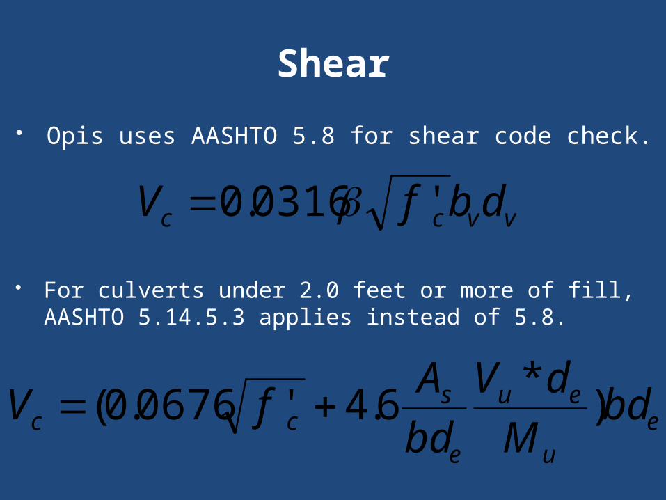
Shear Opis uses AASHTO 5.8 for shear code check.
eu
eu
e
scc bd
MdV
bdAfV )*6.4'0676.0(
vvcc dbfV '0316.0
For culverts under 2.0 feet or more of fill, AASHTO 5.14.5.3 applies instead of 5.8.
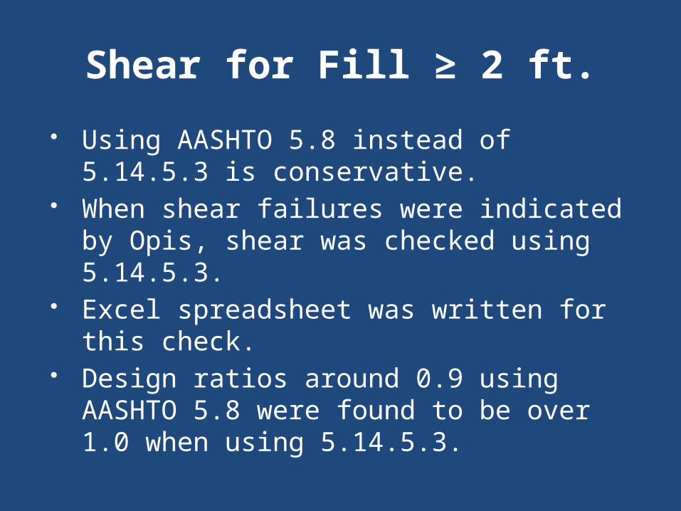
Shear for Fill ≥ 2 ft. Using AASHTO 5.8 instead of 5.14.5.3 is
conservative. When shear failures were indicated by
Opis, shear was checked using 5.14.5.3. Excel spreadsheet was written for this
check. Design ratios around 0.9 using AASHTO
5.8 were found to be over 1.0 when using 5.14.5.3.
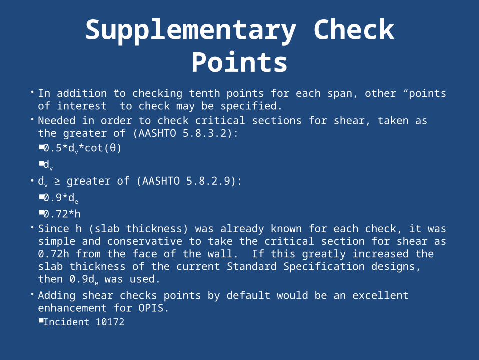
Supplementary Check Points
In addition to checking tenth points for each span, other “points of interest” to check may be specified.
Needed in order to check critical sections for shear, taken as the greater of (AASHTO 5.8.3.2): 0.5*dv*cot(θ) dv
dv ≥ greater of (AASHTO 5.8.2.9): 0.9*de 0.72*h
Since h (slab thickness) was already known for each check, it was simple and conservative to take the critical section for shear as 0.72h from the face of the wall. If this greatly increased the slab thickness of the current Standard Specification designs, then 0.9de was used.
Adding shear checks points by default would be an excellent enhancement for OPIS. Incident 10172

Bridge Alternatives Bridge alternatives are not required for
slab bridges.
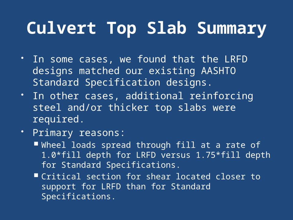
Culvert Top Slab Summary In some cases, we found that the LRFD
designs matched our existing AASHTO Standard Specification designs.
In other cases, additional reinforcing steel and/or thicker top slabs were required.
Primary reasons: Wheel loads spread through fill at a rate of 1.0*fill
depth for LRFD versus 1.75*fill depth for Standard Specifications.
Critical section for shear located closer to support for LRFD than for Standard Specifications.

Reference American Concrete Pipe Association
Very good comparison of the differences between the AASHTO Standard Specifications (17th Ed.) and the AASHTO LRFD Specifications (2008 Interim)
http://www.concrete-pipe.org/pdf/Box-Cliff-Notes.pdf
Standard Drawings TDOT culvert standard drawings can be
found at:
http://www.tdot.state.tn.us/Chief_Engineer/engr_library/stddrlib.htm

Questions?