Embed Size (px)
Citation preview


Filtrosde Aire Turbocharger
Ø .In.5¨Ø.out.10¨
2[x]
Generator
Boxconnection
Aftercooler
Radiator
Startmotor
SIDE VIEW
TOP VIEW
FRONT VIEW107.00
2.50 2.50
145.50
172.
00
46.00144.00144.0046.00380.00
RADIATOR:ENGINE:
# SPRING AVMS:
DESCRIPTION
AIR: FILTER BASE FRAME:
BEARWARD 53494-921VTA 28 G5
AH1101BP-VTA-STF
4 PZS
FO 023-0
MODELSCNE715CNY600
JAN 05th 2005
CUMMINS ENGINE VTA28G5 - STAMFORD ALTERNATOR
Rev.
Customer:
DateDescription
ReviewsCertificated
Date:
Draw:
Title:
Revised:
Scale:
Code:
Dept.: Engineering
Of:
Marks: Draw:
Certificated:
S/O:
s/e
cms
R.G.C. CNE/Y-12F.H.M. F.H.M.
Ottomotores keeps the right to change the information with out prior notice
Date: Date:
-THE GENSET DIMENSIONS ARE THE SAME BY FAMILY MODEL, THERE COULD BE ONLY DIFFERENCES ON THE ALTERNATORLENGHT SEE SPECIFIC GENERAL ARRAGEMENT DRAWING OF CERTEIN MODEL
JAN 05th 2005 JAN 05th 2005
-TOTAL WEIGHT COULD VARY CHECK RATING CHART FOR EACH MODELØ .In.5¨Ø.out.10¨
2[x]
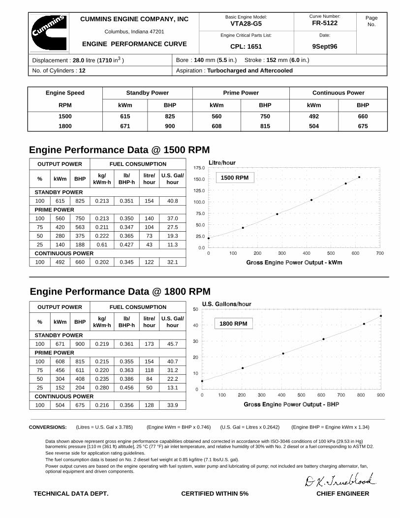
Displacement : 28.0 litre (1710 in3 ) Bore : 140 mm (5.5 in.) Stroke : 152 mm (6.0 in.)
No. of Cylinders : 12 Aspiration : Turbocharged and Aftercooled
OUTPUT POWER FUEL CONSUMPTION
% kWm BHPkg/
kWm·hlb/
BHP·hlitre/hour
U.S. Gal/hour
STANDBY POWER
100 615 825 0.213 0.351 154 40.8
PRIME POWER
100 560 750 0.213 0.350 140 37.0
75 420 563 0.211 0.347 104 27.5
50 280 375 0.222 0.365 73 19.3
25 140 188 0.61 0.427 43 11.3
CONTINUOUS POWER
100 492 660 0.202 0.345 122 32.1
OUTPUT POWER FUEL CONSUMPTION
% kWm BHPkg/
kWm·hlb/
BHP·hlitre/hour
U.S. Gal/hour
STANDBY POWER
100 671 900 0.219 0.361 173 45.7
PRIME POWER
100 608 815 0.215 0.355 154 40.7
75 456 611 0.220 0.363 118 31.2
50 304 408 0.235 0.386 84 22.2
25 152 204 0.280 0.456 50 13.1
CONTINUOUS POWER
100 504 675 0.216 0.356 128 33.9
CUMMINS ENGINE COMPANY, INC
Columbus, Indiana 47201
ENGINE PERFORMANCE CURVE
Curve Number:
FR-5122
Engine Critical Parts List:
CPL: 1651
Date:
9Sept96
PageNo.
Engine Speed Standby Power Prime Power Continuous Power
RPM kWm BHP kWm BHP kWm BHP
1500 615 825 560 750 492 660
1800 671 900 608 815 504 675
CONVERSIONS: (Litres = U.S. Gal x 3.785) (Engine kWm = BHP x 0.746) (U.S. Gal = Litres x 0.2642) (Engine BHP = Engine kWm x 1.34)
Engine Performance Data @ 1500 RPM
Engine Performance Data @ 1800 RPM
1500 RPM
1800 RPM
Data shown above represent gross engine performance capabilities obtained and corrected in accordance with ISO-3046 conditions of 100 kPa (29.53 in Hg)barometric pressure [110 m (361 ft) altitude], 25 °C (77 °F) air inlet temperature, and relative humidity of 30% with No. 2 diesel or a fuel corresponding to ASTM D2.
See reverse side for application rating guidelines.The fuel consumption data is based on No. 2 diesel fuel weight at 0.85 kg/litre (7.1 lbs/U.S. gal).Power output curves are based on the engine operating with fuel system, water pump and lubricating oil pump; not included are battery charging alternator, fan, optional equipment and driven components.
TECHNICAL DATA DEPT. CERTIFIED WITHIN 5% CHIEF ENGINEER
Basic Engine Model:
VTA28-G5
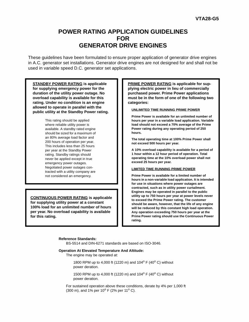
VTA28-G5
POWER RATING APPLICATION GUIDELINESFOR
GENERATOR DRIVE ENGINES
These guidelines have been formulated to ensure proper application of generator drive engines in A.C. generator set installations. Generator drive engines are not designed for and shall not be used in variable speed D.C. generator set applications.
STANDBY POWER RATING is applicable for supplying emergency power for the duration of the utility power outage. No overload capability is available for this rating. Under no condition is an engine allowed to operate in parallel with the public utility at the Standby Power rating.
This rating should be applied where reliable utility power is available. A standby rated engine should be sized for a maximum of an 80% average load factor and 200 hours of operation per year. This includes less than 25 hours per year at the Standby Power rating. Standby ratings should never be applied except in true emergency power outages. Negotiated power outages con-tracted with a utility company are not considered an emergency.
PRIME POWER RATING is applicable for sup-plying electric power in lieu of commercially purchased power. Prime Power applications must be in the form of one of the following two categories:
UNLIMITED TIME RUNNING PRIME POWER
Prime Power is available for an unlimited number of hours per year in a variable load application. Variable load should not exceed a 70% average of the Prime Power rating during any operating period of 250 hours.
The total operating time at 100% Prime Power shall not exceed 500 hours per year.
A 10% overload capability is available for a period of 1 hour within a 12 hour period of operation. Total operating time at the 10% overload power shall not exceed 25 hours per year.
LIMITED TIME RUNNING PRIME POWER
Prime Power is available for a limited number of hours in a non-variable load application. It is intended for use in situations where power outages are contracted, such as in utility power curtailment. Engines may be operated in parallel to the public utility up to 750 hours per year at power levels never to exceed the Prime Power rating. The customer should be aware, however, that the life of any engine will be reduced by this constant high load operation. Any operation exceeding 750 hours per year at the Prime Power rating should use the Continuous Power rating.
CONTINUOUS POWER RATING is applicable for supplying utility power at a constant 100% load for an unlimited number of hours per year. No overload capability is available for this rating.
Reference Standards:BS-5514 and DIN-6271 standards are based on ISO-3046.
Operation At Elevated Temperature And Altitude:The engine may be operated at:
1800 RPM up to 4,000 ft (1220 m) and 104o F (40o C) without power deration.
1500 RPM up to 4,000 ft (1220 m) and 104o F (40o C) without power deration.
For sustained operation above these conditions, derate by 4% per 1,000 ft (300 m), and 1% per 10o F (2% per 11o C).
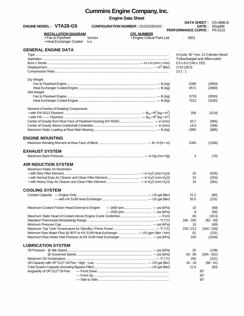
Cummins Engine Company, Inc.Engine Data Sheet
DATA SHEET : DS-4886-BENGINE MODEL : VTA28-G5 CONFIGURATION NUMBER : D153103DX02 DATE : 9Sept96
PERFORMANCE CURVE : FR-5122INSTALLATION DIAGRAM CPL NUMBER • Fan to Flywheel : 3626364 • Engine Critical Parts List : 1651 • Heat Exchanger Cooled : N.A.
GENERAL ENGINE DATAType ............................................................................................................................................................... 4-Cycle; 40° Vee; 12-Cylinder DieselAspiration....................................................................................................................................................... Turbocharged and AftercooledBore x Stroke.............................................................................................................. — in x in (mm x mm) 5.5 x 6.0 (140 x 152)Displacement.............................................................................................................................. — in3
(liter) 1710 (28.0)Compression Ratio........................................................................................................................................ 13.1 : 1
Dry WeightFan to Flywheel Engine.......................................................................................................... — lb (kg) 6395 (2900)Heat Exchanger Cooled Engine............................................................................................ — lb (kg) 6571 (2980)
Wet WeightFan to Flywheel Engine.......................................................................................................... — lb (kg) 6725 (3050)Heat Exchanger Cooled Engine............................................................................................ — lb (kg) 7012 (3180)
Moment of Inertia of Rotating Components • with FW 5013 Flywheel .......................................................................................... — lbm • ft2 (kg • m2) 256 (10.8) • with FW —— Flywheel............................................................................................ — lbm • ft2 (kg • m2)Center of Gravity from Rear Face of Flywheel Housing (FH 5020)........................................ — in (mm) 33.7 (856)Center of Gravity Above Crankshaft Centerline ....................................................................... — in (mm) 14.0 (356)Maximum Static Loading at Rear Main Bearing.......................................................................... — lb (kg) 1950 (885)
ENGINE MOUNTINGMaximum Bending Moment at Rear Face of Block ......................................................... — lb • ft (N • m) 1000 (1356)
EXHAUST SYSTEMMaximum Back Pressure................................................................................................ — in Hg (mm Hg) 3 (76)
AIR INDUCTION SYSTEMMaximum Intake Air Restriction • with Dirty Filter Element......................................................................................... — in H2O (mm H2O) 25 (635) • with Normal Duty Air Cleaner and Clean Filter Element...................................... — in H2O (mm H2O) 10 (254) • with Heavy Duty Air Cleaner and Clean Filter Element....................................... — in H2O (mm H2O) 15 (381)
COOLING SYSTEMCoolant Capacity — Engine Only.................................................................................... — US gal (liter) 21.2 (80)
— with HX 5149 Heat Exchanger...................................................... — US gal (liter) 35.0 (132)
Maximum Coolant Friction Head External to Engine — 1800 rpm................................. — psi (kPa) 10 (69)— 1500 rpm................................. — psi (kPa) 8 (55)
Maximum Static Head of Coolant Above Engine Crank Centerline............................................. — ft (m) 60 (18.3)Standard Thermostat (Modulating) Range................................................................................. — °F (°C) 180 - 200 (82 - 93)Minimum Pressure Cap........................................................................................................... — psi (kPa) 10 (69)Maximum Top Tank Temperature for Standby / Prime Power ................................................. — °F (°C) 220 / 212 (104 / 100)Minimum Raw Water Flow @ 90°F to HX 5149 Heat Exchanger ....................... — US gpm (liter / min) 61 (231)Maximum Raw Water Inlet Pressure at HX 5149 Heat Exchanger...................................... — psi (kPa) 150 (1034)
LUBRICATION SYSTEMOil Pressure @ Idle Speed.................................................................................................... — psi (kPa) 20 (138)
@ Governed Speed ......................................................................................... — psi (kPa) 50 - 90 (345 - 621)Maximum Oil Temperature.......................................................................................................... — °F (°C) 250 (121)Oil Capacity with OP 5127 Oil Pan : High - Low ............................................................... — US gal (liter) 18 - 16 (68 - 61)Total System Capacity (including Bypass Filter)............................................................... — US gal (liter) 21.9 (83)Angularity of OP 5127 Oil Pan — Front Down ..................................................................................... 30°
— Front Up .......................................................................................... 35°— Side to Side..................................................................................... 35°
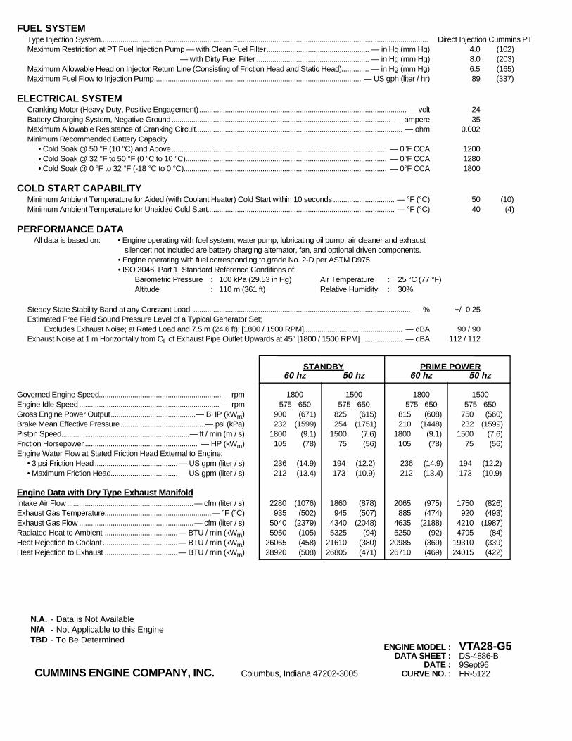
FUEL SYSTEMType Injection System...................................................................................................................................................................... Direct Injection Cummins PTMaximum Restriction at PT Fuel Injection Pump — with Clean Fuel Filter.................................................... — in Hg (mm Hg) 4.0 (102)
— with Dirty Fuel Filter ......................................................... — in Hg (mm Hg) 8.0 (203)Maximum Allowable Head on Injector Return Line (Consisting of Friction Head and Static Head).............. — in Hg (mm Hg) 6.5 (165)Maximum Fuel Flow to Injection Pump......................................................................................................... — US gph (liter / hr) 89 (337)
ELECTRICAL SYSTEMCranking Motor (Heavy Duty, Positive Engagement)......................................................................................................... — volt 24Battery Charging System, Negative Ground............................................................................................................... — ampere 35Maximum Allowable Resistance of Cranking Circuit......................................................................................................... — ohm 0.002Minimum Recommended Battery Capacity
• Cold Soak @ 50 °F (10 °C) and Above............................................................................................................. — 0°F CCA 1200• Cold Soak @ 32 °F to 50 °F (0 °C to 10 °C)...................................................................................................... — 0°F CCA 1280• Cold Soak @ 0 °F to 32 °F (-18 °C to 0 °C)....................................................................................................... — 0°F CCA 1800
COLD START CAPABILITYMinimum Ambient Temperature for Aided (with Coolant Heater) Cold Start within 10 seconds ............................... — °F (°C) 50 (10)Minimum Ambient Temperature for Unaided Cold Start............................................................................................... — °F (°C) 40 (4)
PERFORMANCE DATAAll data is based on: • Engine operating with fuel system, water pump, lubricating oil pump, air cleaner and exhaust
silencer; not included are battery charging alternator, fan, and optional driven components.• Engine operating with fuel corresponding to grade No. 2-D per ASTM D975.• ISO 3046, Part 1, Standard Reference Conditions of:
Barometric Pressure : 100 kPa (29.53 in Hg) Air Temperature : 25 °C (77 °F)Altitude : 110 m (361 ft) Relative Humidity : 30%
Steady State Stability Band at any Constant Load .............................................................................................................. — % +/- 0.25Estimated Free Field Sound Pressure Level of a Typical Generator Set;
Excludes Exhaust Noise; at Rated Load and 7.5 m (24.6 ft); [1800 / 1500 RPM].................................................. — dBA 90 / 90Exhaust Noise at 1 m Horizontally from CL of Exhaust Pipe Outlet Upwards at 45° [1800 / 1500 RPM] ..................... — dBA 112 / 112
STANDBY PRIME POWER60 hz 50 hz 60 hz 50 hz
Governed Engine Speed..............................................................— rpm 1800 1500 1800 1500Engine Idle Speed ....................................................................... — rpm 575 - 650 575 - 650 575 - 650 575 - 650Gross Engine Power Output...........................................— BHP (kWm) 900 (671) 825 (615) 815 (608) 750 (560)Brake Mean Effective Pressure...........................................— psi (kPa) 232 (1599) 254 (1751) 210 (1448) 232 (1599)Piston Speed.................................................................— ft / min (m / s) 1800 (9.1) 1500 (7.6) 1800 (9.1) 1500 (7.6)Friction Horsepower ......................................................... — HP (kWm) 105 (78) 75 (56) 105 (78) 75 (56)Engine Water Flow at Stated Friction Head External to Engine:
• 3 psi Friction Head .......................................... — US gpm (liter / s) 236 (14.9) 194 (12.2) 236 (14.9) 194 (12.2)• Maximum Friction Head.................................. — US gpm (liter / s) 212 (13.4) 173 (10.9) 212 (13.4) 173 (10.9)
Engine Data with Dry Type Exhaust ManifoldIntake Air Flow ................................................................— cfm (liter / s) 2280 (1076) 1860 (878) 2065 (975) 1750 (826)Exhaust Gas Temperature......................................................— °F (°C) 935 (502) 945 (507) 885 (474) 920 (493)Exhaust Gas Flow ..........................................................— cfm (liter / s) 5040 (2379) 4340 (2048) 4635 (2188) 4210 (1987)Radiated Heat to Ambient .....................................— BTU / min (kWm) 5950 (105) 5325 (94) 5250 (92) 4795 (84)Heat Rejection to Coolant ......................................— BTU / min (kWm) 26065 (458) 21610 (380) 20985 (369) 19310 (339)Heat Rejection to Exhaust .....................................— BTU / min (kWm) 28920 (508) 26805 (471) 26710 (469) 24015 (422)
ENGINE MODEL : VTA28-G5DATA SHEET : DS-4886-B
DATE : 9Sept96CUMMINS ENGINE COMPANY, INC. Columbus, Indiana 47202-3005 CURVE NO. : FR-5122
N.A. - Data is Not AvailableN/A - Not Applicable to this EngineTBD - To Be Determined