Embed Size (px)
DESCRIPTION
Current Harmonics Compensation Based on Multiresonant Control in Synchronous Frames for Symmetrical n -Phase Machines
Citation preview

2708 IEEE TRANSACTIONS ON INDUSTRIAL ELECTRONICS, VOL. 62, NO. 5, MAY 2015
Current Harmonics Compensation Based onMultiresonant Control in Synchronous Frames
for Symmetrical n-Phase MachinesAlejandro G. Yepes, Member, IEEE , Jano Malvar, Student Member, IEEE ,
Ana Vidal, Student Member, IEEE , Oscar López, Member, IEEE , andJesús Doval-Gandoy, Member, IEEE
Abstract—Low-order odd current harmonics arise inpractical multiphase drives due to machine and converternonlinear behavior (e.g., deadtime and flux saturation).If the windings are distributed, some harmonics causetorque ripple, whereas others produce losses. The latteris aggravated by the small impedance in the no-torquesubspaces. Current harmonics can be compensated with-out steady-state error by proportional–integral controllersin multiple synchronous frames (SFs); however, a heavycomputational load is required. In three-phase systems, thecomputational burden of this multiple SF (MSF) scheme isoften avoided by implementing instead resonant controllers(RCs) tuned at the harmonics that are multiples of six in anSF rotating with the fundamental frequency. A similar struc-ture has been proposed for nonlinearities compensationin asymmetrical six-phase machines. This paper extendsthis multiple RC (MRC) strategy to symmetrical machinesof any phase number. The optimum frequencies for theRCs and for the SF in each plane, so that the number ofRCs is minimized, are established. Then, the computationalload of the resulting generic MRC scheme is assessed andcompared with that of the MSF structure. The conditionsin which the former is particularly preferable over the latterare identified. Experimental results are provided.
Index Terms—Current control, digital control, machinecontrol, motor drives, multiphase ac drives, variable-speeddrives.
NOMENCLATURE
Variables and transfer functionsGPI
p (z) Proportional–integral (PI) controller in plane p.Gres
p,q(z) Resonant controller (RC) with resonant fre-quencies ±hres
p,qωf placed in a synchronousframe (SF) that rotates with frequency hsf
p ωf
in plane p.h ∈ Z Index that indicates the order of a harmonic of
ωf that is mapped in any of the n subspaces.
Manuscript received April 26, 2014; revised July 4, 2014 andAugust 17, 2014; accepted September 30, 2014. Date of publicationOctober 28, 2014; date of current version April 8, 2015. This work wassupported in part by the Spanish Ministry of Science and Innovation andin part by the European Commission, European Regional DevelopmentFund, under Project DPI2012-31283.
The authors are with the Applied Power Electronics Technology Re-search Group, University of Vigo, 36310 Vigo, Spain (e-mail: [email protected]; [email protected]; [email protected]; [email protected];[email protected]).
Color versions of one or more of the figures in this paper are availableonline at http://ieeexplore.ieee.org.
Digital Object Identifier 10.1109/TIE.2014.2365155
The sign of its value indicates positive or neg-ative sequence.
hp,0 ∈ Z Lowest [in absolute value (ABV)] odd har-monic order in plane p.
h±p,q ∈ Z Positive- (+) or negative-sequence (−) odd
harmonic order in plane p referred by q.hresp,q ∈ N Harmonic order at which Gres
p,q(z) is tuned, sothat its resonant frequencies are ±hres
p,qωf withrespect to the SF in plane p.
hsfp ∈ Z Harmonic order that defines the angular fre-
quency (hsfp ωf ) at which the SF in plane p
rotates.H ∈ N Highest (in ABV) harmonic order h being
controlled.ip Current space vector in plane p.I(z) Discrete-time integrator.Lp Cross-coupling inductanceofSFaxes inplanep.n Number of phases.p ∈ N Plane identifier (p = 1, 2, . . . , P ).q∈N ∪ {0} Index that makes reference to each of the
odd harmonics that are mapped in plane p:hp,0 (q = 0), h+
p,q (q = 1, 2, . . . , Q+p ), and
h−p,q (q = 1, 2, . . . , Q−
p ).Q±
p ∈N ∪ {0} Maximum value of q in plane p for positive(+) or negative sequence (−).
θp Angle of direct rotational transform for the SFin plane p, in the multiple RC (MRC) structure.
u Denotes either voltage v or current i.vp Voltage space vector in plane p.ωf Fundamental frequency of the stator current.Other symbolsx∗ Reference value for x.�x� Maps x to the smallest following integer
(ceiling).�x� Maps x to the largest previous integer (floor).XT Nonconjugated transpose of an array X .
Boldface denotes complex values.
I. INTRODUCTION
MULTIPHASE machines offer many advantages overthree-phase ones. For example, they allow reducing the
torque ripple, as well as the rating per phase and converterswitch [1], [2]. These machines are becoming particularlypopular in those applications that take advantage of their
0278-0046 © 2014 IEEE. Personal use is permitted, but republication/redistribution requires IEEE permission.See http://www.ieee.org/publications_standards/publications/rights/index.html for more information.

YEPES et al.: CURRENT HARMONICS COMPENSATION BASED ON MULTIRESONANT CONTROL IN SFS 2709
enhanced fault tolerance capability [3]–[6]. In addition, it hasbeen recently shown that the increased number of phases can bealso exploited, in wind generation systems, to reduce the dc-linkvoltage to which the ac/dc converters are subjected [7]. In thismanner, multiphase drives have become a topic of increasinginterest in recent years for industry and research [1]–[16].
The model of a multiphase machine with distributed wind-ings can be divided into one α–β plane, in which the electrome-chanical coupling takes place, and several orthogonal subspacesthat can only give rise to losses: a number of x–y planes andone or two homopolar axes [1], [2]. Even when using suitablepulsewidth modulation (PWM) methods, significant currentharmonics arise in practice. These harmonics are mainly dueto the inverter and machine nonlinear behavior (e.g., switchdeadtime and flux saturation) [8]–[10], [13]. The ones mappedin the α–β plane cause undesired effects such as torque rippleand errors in sensorless algorithms; in fact, the cancellationof such disturbances has attracted a considerable attention inthree-phase machines, in which such plane is the only existingone [17], [18]. However, in multiphase drives, more special careshould be taken with the harmonics mapped in the additionalno-torque subspaces, since the low impedance in them leadsto large current (and hence losses) even if the correspondingvoltage harmonics have small amplitude [8].
The possibility of using a multiple SF (MSF) scheme basedon PI controllers in several SFs in parallel (one per harmonic)has been suggested to actively cancel the current harmonicsin multiphase machines [8], analogously to other applicationsin which the MSF approach is adopted to attain zero steady-state state error at various harmonics [19], [20]. Nevertheless,this scheme requires many frame transformations, and hence asignificant computational burden [8], [20].
Concerning three-phase systems, extensive research has beencarried out with regard to control of multiple harmonics withoutsteady-state error and optimized computational load. In contrastto MSF control, a considerable simplification is achieved byimplementing RCs in an SF rotating with the fundamentalfrequency [20]–[23]. A single RC implemented in the funda-mental SF and tuned at a harmonic order that is a multipleof six (i.e., 6k) is able to control two harmonics simultane-ously without steady-state error, because both the 6k − 1 and6k + 1 ones are transformed into a harmonic of order 6k inthe SF (neglecting imbalance and asymmetries) [20]–[23]. Asimilar control structure, based on the implementation of anRC tuned at the sixth harmonic in an SF rotating with thenegative-sequence1 fundamental frequency in the x–y plane,has been proved to be satisfactory for harmonics compensationin asymmetrical six-phase machines [9]. However, it is cur-rently unknown if this MRC strategy can be applied to machineswith phase number n different from six. Furthermore, evenif such extension is possible, its realization is not straightfor-ward, because the harmonic mapping depends on the phasenumber [12].
Additionally, while the computational load of the MSF andMRC schemes has been previously quantified in terms ofnumber of operations and memory allocation in three-phaseapplications [20], the resources needed in multiphase systems
1Positive or negative sequence means that a given space vector rotates incounterclockwise or clockwise direction in its plane, respectively [11].
are expected to be considerably different, as a consequence ofthe modification in the harmonic mapping.
This paper addresses the compensation of current harmonicsin symmetrical multiphase drives that are due to machine andconverter nonlinearities by means of RCs placed in a singleSF per plane. The well-known three-phase MRC strategy isextended to any number of phases. The optimum combinationsof frequencies for the SF and RCs in each plane are assessedas a function of the number of phases and of the harmonicsto be compensated. In addition, the computational burden ofthe MSF and MRC schemes is compared in terms of numberof operations and memory allocation, depending on the phasenumber and on the highest harmonic order to be compensated.
A preliminary version, only accompanied by steady-statesimulation results (for 7- and 12-phase synchronous machines),has been presented at a conference [24], [25]. Now, exper-imental results with a five-phase induction machine, includ-ing both steady-state and transient conditions, are provided.Moreover, several technical mistakes are corrected, and thetheory presentation is enhanced to facilitate its understandingand straightforwardness for practical application.
This paper is organized as follows. Some preliminariesare briefly reviewed in Section II. Then, Section III extendsthe MRC strategy to n phases. The computational loads ofthe MSF and MRC structures are assessed and compared inSection IV. Experimental results are provided in Section V.Finally, Section VI concludes this paper.
II. PRELIMINARIES
A. Division Into Torque and No-Torque Planes
The model of an n-phase machine can be divided into 1 +�n/2� orthogonal subspaces [1], [2], [11]. If the windings aredistributed, only one allows coupling with the rotor and henceflux/torque production: the α–β plane. Thus, to reduce thelosses, the current should be canceled in the other subspaces,which consist of several x–y planes (�n/2� − 2 of them) andone (if n is odd) or two (if n is even) homopolar axes [1],[2]. For the sake of simplicity and without loss of generality,2
the neutral points are assumed to be set so that there is nohomopolar current [1], [9]. Additionally, only symmetricalwindings are considered. If u denotes either voltage v or currenti, the space vector up in each plane p = 1, 2, . . . , P is obtainedby multiplication of the instantaneous per-phase values by thetransformation matrix T [11], i.e.,
[u1 u2 · · · up · · · uP ]T = T [ua ub · · · un ]T ;
T =1
n
⎡⎢⎢⎢⎢⎢⎢⎢⎢⎢⎣
a0 a1 a2 · · · an−1
a0 a2 a4 · · · a(n−1)2
a0 a3 a6 · · · a(n−1)3
......
.... . .
...a0 ap a2p · · · a(n−1)p
......
.... . .
...a0 aP a2P · · · a(n−1)P
⎤⎥⎥⎥⎥⎥⎥⎥⎥⎥⎦
∣∣∣∣∣∣∣∣∣∣∣∣∣∣∣
αβxy1xy2
...xyp−1
...xyP−1
(1)
2An SF implementation in a single-axis subspace is difficult to achieve invariable-speed applications. Thus, control of homopolar current harmonics bycombining RCs and SFs is discarded. Alternatives such as RCs in stationaryframe should be applied instead to the homopolar axes [26], if necessary.
2710 IEEE TRANSACTIONS ON INDUSTRIAL ELECTRONICS, VOL. 62, NO. 5, MAY 2015
where a = ej2π/n, and the right-hand column in T indicatesthe plane onto which each row projects the input vector.The scaling factor 1/n yields the magnitude-invariant formof T [27], whereas 1/
√n would result in the power-invariant
one [11]. These factors should be replaced by 2/n and√
2/n,respectively, when the per-phase instantaneous values in (1) arereal- rather than complex-valued (e.g., once implemented in theactual application), since cos(θ) = (ejθ + e−jθ)/2.
B. Low-Order Harmonics in Multiphase Drives
The amplitude of the hth voltage harmonic due to deadtimeat the output of a multiphase voltage source converter (VSC) isapproximately [8]
Vh =4
π
fswTdVdc
|h| (2)
where fsw is the switching frequency, Td is the deadtime, andVdc is the dc-link voltage. Additional voltage harmonics mayarise because of other nonlinear effects such as flux saturation[10], [13]. Usually, these voltage harmonics are odd and havesmall magnitude, although they can give rise to large currentcomponents [8], [9], [13].
III. EXTENSION OF MRC STRATEGY TO n PHASES
A. Harmonic Mapping Considering Frequencyand Sequence
Analytical expressions have been previously provided for themapping of time harmonics (i.e., voltage and current harmon-ics) in multiphase machines [1], [12]. However, differently fromexisting publications, in order to calculate the optimum RC andSF frequencies, it is here necessary to find equations that givethe harmonic orders as a function of p and n while includingexplicit information about the sequence.
1) Development of Harmonic Mapping Equations:First, the vector of per-phase instantaneous values is expressedas a sum of harmonic components [12], i.e.,
[ua ub · · · un ]T =
H∑h
{Uhe
j(hωf t+γh)
· [a0 a−h a−2h · · · a−(n−1)h ]T}
(3)
where Uh and γh are the amplitude and initial phase of thehth harmonic, respectively; ωf is the fundamental frequency;and t is time. Both positive and negative values of h ∈ Z areconsidered, which will allow discerning the sequences. All oddharmonic orders h up to (in ABV) a certain H ∈ N are takeninto account. By substitution of (3) into (1), the space vector inplane p results in
up =1√n
H∑h
[Uhe
j(hωf t+γh)n−1∑κ=0
aκ(p−h)
]. (4)
From (4) and the roots of unity theory [12], an hth harmonicwith Uh = 0 contributes to up if and only if p− h = ∓nq′, withq′ ∈ N ∪ {0}. This equation is rewritten as
h = p± nq′. (5)
Note that no odd harmonics are mapped in plane p if both p andn are even.
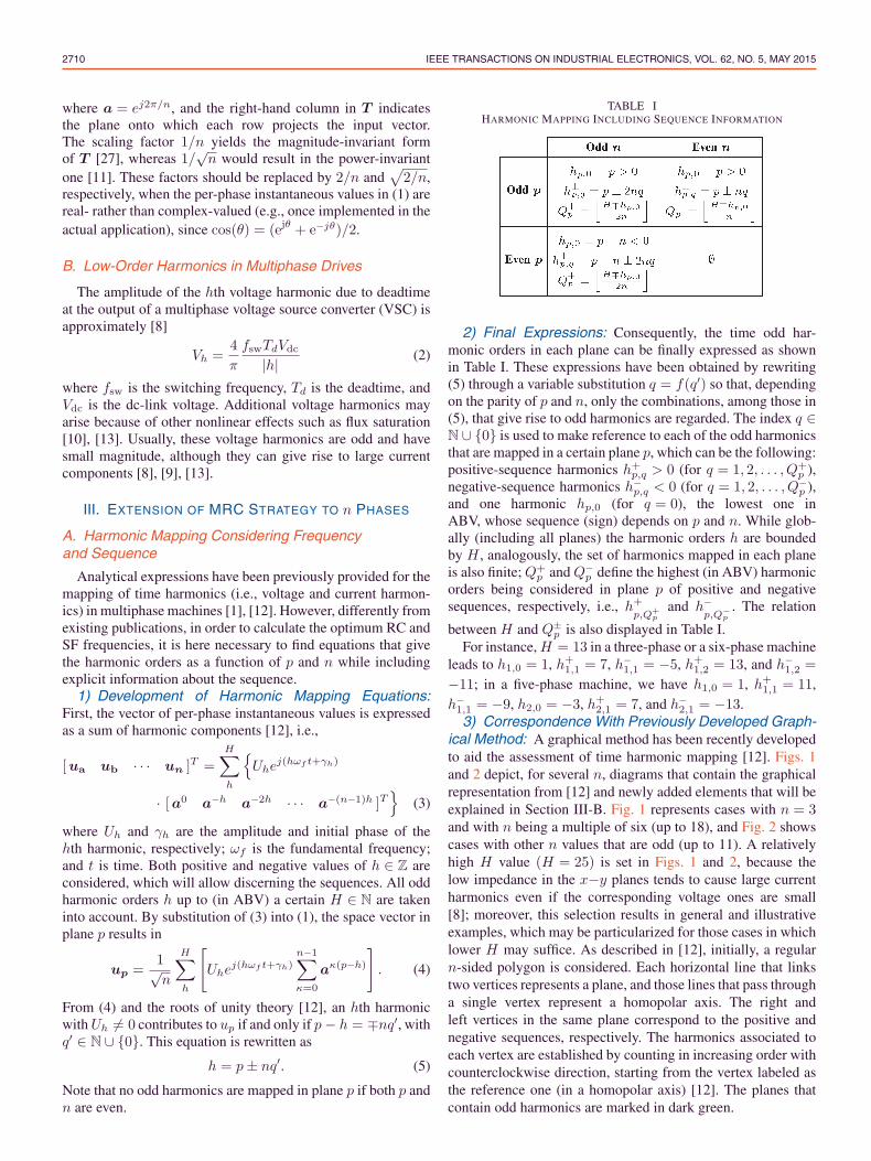
TABLE IHARMONIC MAPPING INCLUDING SEQUENCE INFORMATION
2) Final Expressions: Consequently, the time odd har-monic orders in each plane can be finally expressed as shownin Table I. These expressions have been obtained by rewriting(5) through a variable substitution q = f(q′) so that, dependingon the parity of p and n, only the combinations, among those in(5), that give rise to odd harmonics are regarded. The index q ∈N ∪ {0} is used to make reference to each of the odd harmonicsthat are mapped in a certain plane p, which can be the following:positive-sequence harmonics h+
p,q > 0 (for q = 1, 2, . . . , Q+p ),
negative-sequence harmonics h−p,q < 0 (for q = 1, 2, . . . , Q−
p ),and one harmonic hp,0 (for q = 0), the lowest one inABV, whose sequence (sign) depends on p and n. While glob-ally (including all planes) the harmonic orders h are boundedby H , analogously, the set of harmonics mapped in each planeis also finite; Q+
p and Q−p define the highest (in ABV) harmonic
orders being considered in plane p of positive and negativesequences, respectively, i.e., h+
p,Q+p
and h−p,Q−
p. The relation
between H and Q±p is also displayed in Table I.
For instance, H = 13 in a three-phase or a six-phase machineleads to h1,0 = 1, h+
1,1 = 7, h−1,1 = −5, h+
1,2 = 13, and h−1,2 =
−11; in a five-phase machine, we have h1,0 = 1, h+1,1 = 11,
h−1,1 = −9, h2,0 = −3, h+
2,1 = 7, and h−2,1 = −13.
3) Correspondence With Previously Developed Graph-ical Method: A graphical method has been recently developedto aid the assessment of time harmonic mapping [12]. Figs. 1and 2 depict, for several n, diagrams that contain the graphicalrepresentation from [12] and newly added elements that will beexplained in Section III-B. Fig. 1 represents cases with n = 3and with n being a multiple of six (up to 18), and Fig. 2 showscases with other n values that are odd (up to 11). A relativelyhigh H value (H = 25) is set in Figs. 1 and 2, because thelow impedance in the x−y planes tends to cause large currentharmonics even if the corresponding voltage ones are small[8]; moreover, this selection results in general and illustrativeexamples, which may be particularized for those cases in whichlower H may suffice. As described in [12], initially, a regularn-sided polygon is considered. Each horizontal line that linkstwo vertices represents a plane, and those lines that pass througha single vertex represent a homopolar axis. The right andleft vertices in the same plane correspond to the positive andnegative sequences, respectively. The harmonics associated toeach vertex are established by counting in increasing order withcounterclockwise direction, starting from the vertex labeled asthe reference one (in a homopolar axis) [12]. The planes thatcontain odd harmonics are marked in dark green.

YEPES et al.: CURRENT HARMONICS COMPENSATION BASED ON MULTIRESONANT CONTROL IN SFS 2711
Fig. 1. Graphical representation of the controllers with H = 25, for n = 3 and for n being a multiple of six. (a) n = 3. (b) n = 6. (c) n = 12.(d) n = 18.
The harmonics indicated in Figs. 1 and 2 match those pre-dicted by the compact expressions in Table I.
B. Assessment of Optimum RC and SF Frequencies
1) Graphical Assessment: A simple procedure is de-scribed in the following to obtain, from the harmonic mappingdiagrams drawn in Section III-A3, the optimum harmonic or-ders at which the RCs and the SFs should be tuned.
First, a scaled axis is added to each plane in Figs. 1 and 2, andthe harmonic orders contained in each of them are marked byvertical blue arrows. It can be observed that all the harmonicsmapped in a plane are equally spaced among themselves, inagreement with Table I (see the ±nq and ±2nq terms). Thisfact makes it possible to apply the subsequent steps.
If a given harmonic h+p,q or h−
p,q is expressed with respect toan SF that rotates at hsf
p ωf , it is transformed into a harmonicof order h+
p,q − hsfp or h−
p,q − hsfp , respectively [19]. An RC
Gresp,q(z) achieves zero steady-state error at the resonant frequen-
cies ±hresp,qωf in closed loop [20]. Thus, hsf
p and hresp,q can be
calculated from the diagrams as follows.
• hsfp is the mean between the harmonic orders h+
p,Q+p
and
h−p,Q−
p(considering their sign).
• hresp,q is given by the subtraction of hsf
p from h+p,q (or,
equivalently, hresp,q = |h−
p,q − hsfp |).
In this manner, the specific controllers that should be im-plemented to compensate each of the harmonics, according tothese rules, are added to Figs. 1 and 2. The vertical dashed redlines indicate the harmonic order with which the SF in plane pis synchronized, i.e., hsf
p . The resulting graphical representationfor each plane can be understood as an extrapolation of thatshown in [20] (for n = 3) to n > 3.
Note that, if Q+p = Q−
p , the harmonic hp,0 can be controlledby including an integral term I(z) (leading to a PI controllerGPI
p (z)) in the SF, because hsfp = hp,0, which means that this
harmonic is seen as a dc component in the SF. Otherwise, whenQ+
p = Q−p , the integrator I(z) can be omitted. If Q+
1 < Q−1 , it
is convenient to increase Q+1 (or to decrease Q−
1 ) in a unit sothat Q+
1 = Q−1 and hsf
1 = 1; in this manner, the flux and torquecan be regulated by an I(z) term rotating at ωf in the α−βplane in the conventional way [1], [8], [28].
When both p and n are even, for which, ideally, there are noodd harmonics (see Table I), no control is needed in plane p.That occurs, for example, in Fig. 1(b)–(d). In any case, a simplecontroller (not shown in the figures) may be included just forasymmetries compensation [9], if deemed necessary.

2712 IEEE TRANSACTIONS ON INDUSTRIAL ELECTRONICS, VOL. 62, NO. 5, MAY 2015
Fig. 2. Graphical representation of the controllers with H = 25, for odd n > 3. (a) n = 5. (b) n = 7. (c) n = 9. (d) n = 11.
2) Analytical Assessment: Next, closed-form expressionsare derived for hsf
p and hresp,q . Such equations can be useful for
computer-based algorithms (e.g., the analysis of computationalburden in Section IV), for designing the control scheme for agiven machine rather than by the graphical method, etc.
It follows from Table I (or from the harmonic mappingdiagrams from Section III-A3) that the difference betweenQ+
p and Q−p may be −1, 0, or 1. Therefore, each RC should
simultaneously cancel either the pair of harmonics h+p,q−1 and
h−p,q (if Q+
p −Q−p = −1), h+
p,q and h−p,q (if Q+
p −Q−p = 0), or
h+p,q and h−
p,q−1 (if Q+p −Q−
p = 1). Consequently, the SF tobe implemented in a plane p should be rotating at a frequencyhsfp ωf such that these positive- and negative-sequence harmon-
ics are transformed into harmonics of identical order in ABV(pairwise) hres
p,q in that SF, i.e.,
hresp,q=h+
p,q − hsfp = −
(h−p,q − hsf
p
), if Q+
p −Q−p = 0
hresp,q =h+
p,q − hsfp = −
(h−p,q−1 − hsf
p
), if Q+
p −Q−p = 1
hresp,q=h+
p,q−1 − hsfp = −
(h−p,q − hsf
p
), if Q+
p −Q−p = −1. (6)
Isolation of hsfp from (6) and combination with Table I results
in the hsfp expressions shown in Table II. Then, substitution of
TABLE IIOPTIMUM COMBINATIONS OF RC AND SF HARMONIC ORDERS
the h+p,q and hsf
p equations from Tables I and II, respectively,in (6) gives that the RCs in the SF rotating at hsf
p ωf should betuned at hres
p,q , which is also detailed in Table II. To obtain thenumerical hsf
p and hresp,q values from the equations for a certain
application, the designer should first calculate Q±p from H by
means of Table I and then directly use Table II.The parameters hsf
p and hresp,q from Figs. 1 and 2 satisfy the
developed equations shown in Table II.Particularization of the theory for n = 3 results in the well-
known approach based on RCs (Q+1 = Q−
1 of them) tuned athres1,q = 6q and one PI controller, all of them implemented in an
SF rotating with hsf1 = 1 in p = 1, as in [20]–[23].

YEPES et al.: CURRENT HARMONICS COMPENSATION BASED ON MULTIRESONANT CONTROL IN SFS 2713
Fig. 3. Generic MRC scheme for an n-phase machine.
C. Multiphase MRC Structure
Fig. 3 depicts the n-phase MRC scheme. The subscripts andsuperscripts of Q are omitted. The references isf
∗
p are zero forp = 1. The inductance Lp, used for cross-coupling decouplingof SF axes, is equal to the stator leakage inductance for p = 1,whereas L1 is defined depending on the machine type [28].
The discrete-time integrators I(z) are assumed to be obtainedby the Tustin method, which produces low distortion in thefrequency response [19]. Hence, the PI controller in plane pcan be expressed as
GPIp (z) = KP
p +KIp
I(z)︷ ︸︸ ︷Ts
2
1 + z−1
1− z−1(7)
where KPp and KI
p are the proportional and integral gains,respectively. The I(z) blocks in the x−y planes are shown withdashed line in Fig. 3 to emphasize the fact that they can beomitted when hsf
p = hp,0, as mentioned in Section III-B1.The angles of the inverse and direct rotational transforma-
tions of the SF in plane p are set so that θ′p − θp = 1.5hsfp ωfTs,
where Ts is the sampling period, to compensate the phase lag athsfp ωf due to the one and a half sample delay, which is related
to computation and modulation [22], [29].Among proportional–resonant and vector PI controllers, the
former type of RC is selected because of its greater gainat frequencies different from the resonant ones [30], such asthose of interharmonics or disturbances due to asymmetries. Asuitable discrete-time implementation is given by the impulseinvariant method [31], [32], i.e.,
Gresp,q(z)=Kres
p,qTs
cos(φ′p,q
)−z−1 cos
(φ′p,q−hres
p,qωfTs
)1−2z−1 cos
(hresp,qωfTs
)+z−2
(8)
where Kresp,q is a gain, and φ′
p,q is a phase lead added inopen loop at the resonant frequencies ±hres
p,qωf to improve thedynamics [31], [32].
If cancellation without steady-state error is desired as wellfor the positive- or negative-sequence fundamental componentthat may arise in the x–y planes due to asymmetries, anadditional controller can be included (not shown in Fig. 3) inparallel with the SFs. For instance, a pair of SFs rotating at±ωf with integrators, or an equivalent RC in stationary frame,would suffice [9].
IV. ANALYSIS OF COMPUTATIONAL LOAD
First, in Section IV-A, then-phase MSF implementation is de-scribed. Then, some clarifications are made in Section IV-Babout the computations associated to certain functions of boththe MSF and MRC structures, in relation to [25]. Finally,the computational loads of the MSF and MRC strategies arecompared in Section IV-C.
A. Multiphase MSF Structure
Fig. 4 depicts the block diagram of the n-phase MSF ap-proach. Note that, extending for n phases, the MSF structureis much more straightforward than the MRC one. To simplifythe representation, the superscripts and subscripts of Q areignored, and it is assumed that the initial phase is zero, i.e.,θ1 = ωf t. Since a proportional gain is not affected by rotationaltransformations, all the proportional gains that would resultfrom implementing a PI controller per SF are aggregated intoa single total proportional gain KP
p for each plane p [19]. Thegains for the integrators I(z) rotating at hp,0ωf and h±
p,qωf aredenoted by Kp,0 and K±
p,q , respectively.It is not recommendable to add cross-coupling decoupling
operations to more than one SF in the same plane, sincethe decoupling lines would interfere among themselves [33].Therefore, the decoupling technique is only implemented in theα–β plane for the fundamental component (see Fig. 4), so thatit provides an enhancement in the torque and flux dynamics, asis usually done for n = 3 [28], [29].
To compensate the phase lag of the plant and the time delay,the leading angles φ+
p,q and φ−p,q are added in the inverse
rotational transformations, as shown in Fig. 4.

2714 IEEE TRANSACTIONS ON INDUSTRIAL ELECTRONICS, VOL. 62, NO. 5, MAY 2015
Fig. 4. Generic MSF scheme for an n-phase machine.
B. Further Details About Implementationand Computation
Additional details about the implementation and resourcesassociated to each of the blocks of the MSF and MRC schemescan be found in [25]. In any case, there are some points from[25] that are worth clarifying for the sake of completeness.
It is considered in [25] that the angles (φ′p,q in RCs or
φ+p,q and φ−
p,q in the MSF approach) are set so that a phaselead 1.5hωfTs ± π/2 is added at each harmonic h, but this
may not be convenient if ωfLp/Rs is too small [32], with Rs
being the stator winding resistance. For such cases, it may be abetter choice to use 2hωfTs, as can be inferred from the open-loop phase versus frequency response [32]. Nevertheless, theselection among these alternatives hardly affects the differencebetween the MSF and MRC schemes in terms of global com-putational burden [25].
The trigonometric functions are assumed here to be calcu-lated by Taylor series of sixth order, for both the RCs and SFs,as in [25]. However, while the arguments in the trigonometricfunctions are small in RCs [32], those in the SFs vary betweenzero and 2π. Hence, to achieve acceptable accuracy with asixth-order approximation for the SFs, the sine and cosinefunctions in the rotational transformations should be carefullyprogrammed so that their period can be divided into, e.g., foursymmetric parts. If, for simplicity, direct calculation by Taylorseries is preferred, then a much higher order of approximationshould be chosen for the SFs (e.g., 18th), and then, the MRCscheme would become even more computationally advanta-geous in comparison with the MSF one, even for relativelylow H .
Asymmetries compensation is not taken into account for thefollowing comparison, as it would not make any differencebetween the MSF and MRC structures [25].
C. Computational Load Analysis as a Functionof n and H
In modern digital signal processors and microcontrollers,additions and multiplications usually require the same numberof clock cycles. Hence, both types of calculations are hereconsidered together.
The resulting total numbers of operations for the MSF andMRC structures are shown in Fig. 5 for different n. The totalnumber of delays z−1 (i.e., stored variables) is displayed inFig. 6. Although the n = 3 case has been already studied [20],it is also included here to facilitate the comparison.
From these figures, in certain conditions, the curves nearly(or completely) overlap, whereas in some others, the MRCstructure exhibits a significant simplification.
It has been concluded by Etxeberria-Otadui et al. [20] that,for n = 3, the computational advantage in comparison withMSF control increases with H [see Figs. 5(a) and 6(a)]. Thisbehavior is explained by the fact that, as the number of harmon-ics to be controlled is incremented, there are more RCs in theSF; thus, the operations related to the rotational transformationsof that SF become negligible as H grows, with respect to thetotal computations. From Figs. 5 and 6, in general, the savingin computational burden also increases with H when n > 3,because, as can be observed in Figs. 1 and 2, the proportionbetween the number of RCs and the number of SFs rises withH also if n > 3.
It can be observed in Figs. 5 and 6 that, in addition to H , thedifference in resources is also considerably altered by n. First,two different groups should be distinguished: the machineswith odd n and those with even n (e.g., n = 6k, with k ∈ N).This distinction is made because, when n is even, no oddharmonics are mapped in �n/4− 1� of the x−y planes [see

YEPES et al.: CURRENT HARMONICS COMPENSATION BASED ON MULTIRESONANT CONTROL IN SFS 2715
Fig. 5. Number of operations of the MSF and MRC schemes depend-ing on n and H. (a) n = 3, 6. (b) n = 5, 7. (c) n = 9, 11. (d) n = 12, 18.
Fig. 6. Number of stored variables of the MSF and MRC schemesdepending on n and H. (a) n = 3, 6. (b) n = 5, 7. (c) n = 9, 11.(d) n = 12, 18.

2716 IEEE TRANSACTIONS ON INDUSTRIAL ELECTRONICS, VOL. 62, NO. 5, MAY 2015
TABLE IIIPARAMETERS OF THE MACHINE IN THE EXPERIMENTAL PROTOTYPE
Table I and Fig. 1(b)–(d)]. In this manner, the difference incomputations between MRC and MSF control is bigger foreven n than for odd n (for similar n), as shown in Figs. 5and 6, since, for even n, there is a higher number of RCs perSF [compare Fig. 1(b)–(d) with Fig. 2]. Within each of thesetwo groups (i.e., odd or even n), the number of RCs per SFdecreases as n becomes greater, hence leading to a reductionin the computational saving attained by the MRC strategy withrespect to the MSF one (see Figs. 5 and 6).
It is worth noticing that the MRC curves in Fig. 5 exhibita decrease in slope at a specific H value (Hc). This changetakes place once there are three harmonics in any of the planes,because the control of the third harmonic is achieved with veryfew additional operations in the MRC scheme with respect toH = 2. By inspection of Table I and Figs. 1 and 2, it is deducedthat the first time (for increasing H) this condition occurs iswhen H = h+
1,1, for either even or odd n. Also from Table I,h+1,1 is equal to 1 + n or 1 + 2n depending on whether n is even
or odd, respectively; thus, a critical threshold can be defined atthe preceding odd harmonic order, i.e.,
Hc =n− 1, if n is even
Hc =2n− 1, if n is odd. (9)
Actually, (9) coincides with the abscissa values at which theMRC curves begin to deviate more substantially from the MSFones in Fig. 5. In addition, there is a certain reduction in theslope of the MRC curve in Fig. 6 at Hc; nevertheless, it is notas relevant as in Fig. 5.
V. EXPERIMENTAL RESULTS
The experiments are performed with a five-phase inductionmachine with double-layer windings. Simulation results with7- and 12-phase synchronous machines were presented at theconference [24]. The parameters of the machine used in thelaboratory prototype, which are shown in Table III, have beenidentified by the methods proposed in [11]. The magnetizinginductance of the x–y plane [14] is disregarded for the estima-tion and the control dynamics. The variation of the parameterswith frequency is much less significant than in the machinesstudied in [11]. This five-phase machine has been obtained byrewinding a three-phase one, whose rated values of power, linevoltage, current, and speed for star connection were 750 W,380 V, 1.3 A, and 1440 r/min, respectively. The rated voltagehas been kept after the rewinding process.
The VSC is based on insulated-gate bipolar transistors. Thedc-link voltage is Vdc = 750 V, so that there is enough output
voltage capability to provide high peak torques by momentarilysupplying very large current [34]. There is no need to substan-tially increase Vdc to provide the current harmonics cancellationfunctionality, since the corresponding voltage harmonics areusually small (see Section II-B); if such was not the case, Vdc
would have to be raised accordingly.The control is implemented in a dSPACE MABXII DS1401
platform. The sampling and switching frequencies are fs =fsw = 10 kHz. The torque and flux are regulated by indirectrotor field oriented control (IRFOC) [28]. The flux referenceis reduced in inverse relation to the speed in the constant-power region [28]. The gains of the current PI controllersare tuned according to the internal model principle, with abandwidth of 3.9% of fs in the α−β plane (for minimumovershoot and settling time when isf
∗
1 changes) and of 10%of fs in the x–y plane (for better disturbance rejection) [29].For further information about the dynamic response providedby other bandwidth selections for the PI controllers, both fromthe command-tracking and disturbance-rejection viewpoints,see [29] and the publications cited therein. It should be alsoremarked that the addition of the RCs to the PI one in a givenplane only alters the frequency response around their resonantfrequencies (providing zero steady-state error), because of theirselective nature [30]. The gains of all RCs are set to Kres
p,q =4000, taking into account selectivity, transient response, andstability [30]. A phase lead φ′
p,q of two samples [31] is chosenfor the RCs (see Section IV-B). The magnitude-invariant formof T is adopted.
Concerning antiwindup protection, back-calculationschemes as those described in [35] and [36] are adopted for thePI and RCs, respectively.
The rotor speed ωm is obtained by processing the pulses(1024 per turn) from an incremental encoder by means ofa field-programmable gate array (FPGA), with a time-stamp-based velocity calculation algorithm: the time between risingedges is measured, and the number of edges is adjusted to thesampling period of the main control task Ts = 1/fs. The posi-tion and speed of the rotor flux are calculated by multiplicationof the slip gain and the q-axis current reference, according toIRFOC [28].
Note that the Rs value shown in Table III (which coincideswith its dc measurement) is very large. In a well-designedmachine for practical industry applications, much lower Rs
and copper losses are expected. For example, a real 12-phasemachine with Rs = 7 mΩ and low leakage inductances isstudied in [13], and external reactors are added to passivelyattenuate the x–y current harmonics at the expense of mod-erately increasing the copper losses. Theoretically, increasingthe deadtime Td has the same effect on the current harmonicamplitudes [see (2)] as lowering the impedance in the samequantity; therefore, to achieve a closer current spectrum to a realapplication (ignoring external reactors [13], as the harmonicsare actively compensated), Td is here artificially increased to12 μs. A reasonable Td would be about 3 μs (as was usedfor the simulation results presented at the conference [24]);thus, such Td rise yields similar current harmonic amplitudesas dividing the impedance by four. Moreover, although in somepractical multiphase drives the harmonic content may not be

YEPES et al.: CURRENT HARMONICS COMPENSATION BASED ON MULTIRESONANT CONTROL IN SFS 2717
Fig. 7. Steady-state results at ωm = 2100 r/min, with only a PI con-troller in SF in the α−β plane (H = 1). (a) Current projections on theorthogonal axes. (b) Phase-a current.
as substantial as in this case, and it may not be necessaryto compensate as many harmonics, the results shown for thisscenario also prove that the MRC strategy would be able tocompensate the current harmonics in less demanding situations.
A. Steady-State Results
Fig. 7 shows the steady-state current components obtainedwhen there is only a PI controller in SF in the α−β plane(i.e., H = 1) and the rotor rotates at a mechanical speed ωm =2100 r/min. A relatively high ωm has been chosen so that theharmonic rejection capability of the RCs can be more clearlyassessed subsequently, since the attenuation provided by theproportional gains KP
1 and KP2 decreases with frequency [30],
[31]. The signals included in Fig. 7(a) are id1= Re{isf1 },
iq1 = Im{isf1 }, ix = Re{i2}, and iy = Im{i2}. On the otherhand, Fig. 7(b) shows the phase-a current, directly measuredby a current probe (ia) and with its switching harmonics beingfiltered by the FPGA with a sampling frequency of 10 MHz(ifilta ). The coupling mode for id1
and iq1 is set to ac, so thattheir average value is removed.
In Fig. 7(b), the phase current is highly distorted. As ex-pected, the largest harmonics are those mapped in the x–y plane[see Fig. 7(a)], although there are also some oscillations in id1
and iq1 , associated to torque ripple.Fig. 8 displays analogous signals to Fig. 7, but now with
the complete MRC structure (H = 25). It can be seen that the
Fig. 8. Steady-state results at ωm = 2100 r/min, with MRC (H = 25).(a) Current projections on the orthogonal axes. (b) Phase-a current.
Fig. 9. Spectrum of phase-a current in Figs. 7(b) and 8(b).
current harmonics are almost completely eliminated in bothplanes and that ia is nearly sinusoidal.
Fig. 9 compares the spectrum of ia with H = 1 and H =25. The sign of h is omitted, since ia is real valued. InFig. 2(a), the sets of harmonics |h| = 1, 9, 11, 19, 21 and |h| =3, 7, 13, 17, 23 correspond to the α–β and x–y planes, respec-tively. It can be observed in Fig. 9 that the total harmonicdistortion (THD) is reduced from 18.32% to 0.84%, and all oddharmonics below 25 are substantially attenuated.
Table IV displays the THD obtained by steady-state testsidentical to that shown in Fig. 8, but with different H values,so that the progressive improvement in harmonic cancellationis illustrated. The step from H = 1 to H = 3 also implies the

2718 IEEE TRANSACTIONS ON INDUSTRIAL ELECTRONICS, VOL. 62, NO. 5, MAY 2015
TABLE IVVARIATION OF THD AND COMPUTATIONAL BURDEN WITH H
Fig. 10. Machine start with high torque [34]. The scale of ωm is600 r/min/div. (a) With only a PI controller in SF in the α−β plane(H = 1). (b) With MRC (H = 25).
addition of the proportional part in the x–y plane KP2 . The
computational load that corresponds to each case, according toSection IV, is also included.
B. Transient Results
To test the ability of the MRC scheme to adapt to abruptfrequency variations, a very demanding speed transient isachieved by starting the machine with the procedure of [34].Furthermore, this method implies that i∗1, becomes momen-tarily very high; thus, the flux saturates, and, hence, morecurrent harmonics arise. The results of the speed transient fromωm = 0 r/min to ωm ≈ 1000 r/min are shown in Fig. 10(a) and(b), for H = 1 and H = 25, respectively. The harmonics arealmost totally canceled in spite of the fast ωm change; thus, theeffective adaptation of the MRC scheme to frequency is proved.
On the other hand, Fig. 11 depicts the waveforms obtainedwith a different acceleration test. The machine is initially mov-ing at a speed close to rated, i.e., ωm = 1400 r/min, and then, aω∗m step is applied to an outer speed two-degree-of-freedom PI
Fig. 11. Response to ω∗m step applied at ωm = 1400 r/min. The scale
of ωm is 150 r/min/div. Both (a) and (b) have been taken simultaneously.
regulator [37]. Consequently, a sudden i∗q1 increase is produced,causing the saturation of the VSC output voltage referencev∗ [note the high level of the Boolean variable saturationin Fig. 11(b)]. As shown in Fig. 11, windup problems aresatisfactorily prevented, and the harmonics are compensatedafter a short transient.
VI. CONCLUSION
In this paper, the well-known three-phase MRC strategy foroptimized current harmonic control, based on implementationof a set of RCs in an SF, has been extended to n phases. Theoptimum combinations of frequencies at which the RCs and theSF in each plane should be tuned are assessed as a function of nand the highest harmonic order. In this manner, odd current har-monics due to nonlinear behavior can be compensated withoutsteady-state error in symmetrical multiphase drives.
An analysis of the computational load involved in the MSFand MRC schemes is performed, in terms of number of op-erations and memory allocation. It is proved that the MRCstructure provides a resource saving in comparison with theMSF one that increases as H and n become larger and lower,respectively. This saving is particularly considerable if H isgreater than n− 1 or 2n− 1 in machines with even or odd n,respectively.
Experimental results with a five-phase induction machine,including steady-state and transient operations, are provided.

YEPES et al.: CURRENT HARMONICS COMPENSATION BASED ON MULTIRESONANT CONTROL IN SFS 2719
REFERENCES
[1] E. Levi, “Multiphase electric machines for variable-speed applications,”IEEE Trans. Ind. Electron., vol. 55, no. 5, pp. 1893–1909, May 2008.
[2] E. Levi, R. Bojoi, F. Profumo, H. Toliyat, and S. Williamson, “Multiphaseinduction motor drives—A technology status review,” IET Elect. PowerAppl., vol. 1, no. 4, pp. 489–516, Jul. 2007.
[3] H. Guzman, M. J. Duran, F. Barrero, B. Bogado, and S. Toral, “Speedcontrol of five-phase induction motors with integrated open-phase faultoperation using model-based predictive current control techniques,” IEEETrans. Ind. Electron., vol. 61, no. 9, pp. 4474–4484, Sep. 2014.
[4] A. Mohammadpour, S. Mishra, and L. Parsa, “Fault-tolerant operation ofmultiphase permanent-magnet machines using iterative learning control,”IEEE J. Emerging Sel. Topics Power Electron., vol. 2, no. 2, pp. 201–211,Jun. 2014.
[5] N. Bianchi, E. Fornasiero, and S. Bolognani, “Thermal analysis of a five-phase motor under faulty operations,” IEEE Trans. Ind. Appl., vol. 49,no. 4, pp. 1531–1538, Jul./Aug. 2013.
[6] M. Popescu et al., “Thermal analysis of duplex three-phase inductionmotor under fault operating conditions,” IEEE Trans. Ind. Appl., vol. 49,no. 4, pp. 1523–1530, Jul./Aug. 2013.
[7] H. S. Che et al., “Operation of a six-phase induction machine using series-connected machine-side converters,” IEEE Trans. Ind. Electron., vol. 61,no. 1, pp. 164–176, Jan. 2014.
[8] M. Jones, S. Vukosavic, D. Dujic, and E. Levi, “A synchronous currentcontrol scheme for multiphase induction motor drives,” IEEE Trans.Energy Convers., vol. 24, no. 4, pp. 860–868, Dec. 2009.
[9] H. S. Che, E. Levi, M. Jones, W.-P. Hew, and N. A. Rahim, “Currentcontrol methods for an asymmetrical six-phase induction motor drive,”IEEE Trans. Power Electron., vol. 29, no. 1, pp. 407–417, Jan. 2014.
[10] J. Karttunen, S. Kallio, P. Peltoniemi, P. Silventoinen, and O. Pyrhonen,“Decoupled vector control scheme for dual three-phase permanent mag-net synchronous machines,” IEEE Trans. Ind. Electron., vol. 61, no. 5,pp. 2185–2196, May 2014.
[11] A. G. Yepes et al., “Parameter identification of multiphase induction ma-chines with distributed windings—Part 1: Sinusoidal excitation methods,”IEEE Trans. Energy Convers., vol. 27, no. 4, pp. 1056–1066, Dec. 2012.
[12] J. Malvar et al., “Graphical diagram for subspace and sequence identifi-cation of harmonics in symmetrical multiphase machines,” IEEE Trans.Ind. Electron., vol. 61, no. 1, pp. 29–42, Jan. 2014.
[13] A. Tessarolo and C. Bassi, “Stator harmonic currents in VSI-fed syn-chronous motors with multiple three-phase armature windings,” IEEETrans. Energy Convers., vol. 25, no. 4, pp. 974–982, Dec. 2010.
[14] A. S. Abdel-Khalik, M. I. Daoud, S. Ahmed, A. A. Elserougi, andA. M. Massoud, “Parameter identification of five-phase induction ma-chines with single layer windings,” IEEE Trans. Ind. Electron., vol. 61,no. 10, pp. 5139–5154, Oct. 2014.
[15] M. Mengoni et al., “On-line detection of high-resistance connections inmultiphase induction machines,” IEEE Trans. Power Electron., vol. 30,no. 8, pp. 4505–4513, Aug. 2015.
[16] K. Wang, Z. Q. Zhu, and G. Ombach, “Torque improvement of five-phase surface-mounted permanent magnet machine using third-order har-monic,” IEEE Trans. Energy Convers., vol. 29, no. 3, pp. 735–747,Sep. 2014.
[17] C. Xia, B. Ji, and Y. Yan, “Smooth speed control for low speed hightorque permanent magnet synchronous motor using proportional integralresonant controller,” IEEE Trans. Ind. Electron., vol. 62, no. 4, pp. 2123–2134, Apr. 2015.
[18] D.-M. Park and K.-H. Kim, “Parameter-independent online compensationscheme for dead time and inverter nonlinearity in IPMSM drive throughwaveform analysis,” IEEE Trans. Ind. Electron., vol. 61, no. 2, pp. 701–707, Feb. 2014.
[19] S. Buso and P. Mattavelli, Digital Control in Power Electronics,J. Hudgins, Ed. San Rafael, CA, USA: Morgan & Claypool, 2006.
[20] I. Etxeberria-Otadui, A. Lopez de Heredia, H. Gaztanaga, S. Bacha, andM. Reyero, “A single synchronous frame hybrid (SSFH) multifrequencycontroller for power active filters,” IEEE Trans. Ind. Electron., vol. 53,no. 5, pp. 1640–1648, Oct. 2006.
[21] R. I. Bojoi et al., “Current control strategy for power conditioners using si-nusoidal signal integrators in synchronous reference frame,” IEEE Trans.Power Electron., vol. 20, no. 6, pp. 1402–1412, Nov. 2005.
[22] L. Harnefors, A. G. Yepes, A. Vidal, and J. Doval-Gandoy, “Passivity-based stabilization of resonant current controllers with consideration oftime delay,” IEEE Trans. Power Electron., vol. 29, no. 12, pp. 6260–6263,Dec. 2014.
[23] L. Limongi, R. Bojoi, G. Griva, and A. Tenconi, “Digital current-controlschemes,” IEEE Ind. Electron. Mag., vol. 3, no. 1, pp. 20–31, Mar. 2009.
[24] A. G. Yepes, J. Malvar, A. Vidal, O. Lopez, and J. Doval-Gandoy,“Current harmonic compensation in symmetrical multiphase machinesby resonant controllers in synchronous reference frames—Part 1: Ex-tension to any phase number,” in Proc. IEEE IECON, Vienna, Austria,Nov. 2013, pp. 5155–5160.
[25] A. G. Yepes, J. Malvar, A. Vidal, O. Lopez, and J. Doval-Gandoy, “Cur-rent harmonic compensation in symmetrical multiphase machines by reso-nant controllers in synchronous reference frames—Part 2: Computationalload,” in Proc. IEEE IECON, Vienna, Austria, Nov. 2013, pp. 5161–5166.
[26] J. Zeng, P. Degobert, and J.-P. Hautier, “Minimum torque ripple control ofpermanent magnet synchronous motor in the stationary reference frame,”in Proc. IEEE IEMDC, May 2005, pp. 667–673.
[27] J. Figueroa, J. Cros, and P. Viarouge, “Generalized transformations forpolyphase phase-modulation motors,” IEEE Trans. Energy Convers.,vol. 21, no. 2, pp. 332–341, Jun. 2006.
[28] E. Levi, “FOC: Field oriented control,” in The Industrial ElectronicsHandbook, 2nd ed., vol. Power Electronics and Motor Drives.Boca Raton, FL, USA: CRC Press, 2011.
[29] A. G. Yepes, A. Vidal, J. Malvar, O. Lopez, and J. Doval-Gandoy, “Tuningmethod aimed at optimized settling time and overshoot for synchronousproportional–integral current control in electric machines,” IEEE Trans.Power Electron., vol. 29, no. 6, pp. 3041–3054, Jun. 2014.
[30] A. G. Yepes, F. D. Freijedo, O. Lopez, and J. Doval-Gandoy, “Analysisand design of resonant current controllers for voltage-source convertersby means of Nyquist diagrams and sensitivity function,” IEEE Trans. Ind.Electron., vol. 58, no. 11, pp. 5231–5250, Nov. 2011.
[31] A. G. Yepes et al., “Effects of discretization methods on the performanceof resonant controllers,” IEEE Trans. Power Electron., vol. 25, no. 7,pp. 1692–1712, Jul. 2010.
[32] A. G. Yepes, F. D. Freijedo, O. Lopez, and J. Doval-Gandoy, “High-performance digital resonant controllers implemented with two integra-tors,” IEEE Trans. Power Electron., vol. 26, no. 2, pp. 563–576, Feb. 2011.
[33] A. G. Yepes, A. Vidal, O. Lopez, and J. Doval-Gandoy, “Evaluationof techniques for cross-coupling decoupling between orthogonal axes indouble synchronous reference frame current control,” IEEE Trans. Ind.Electron., vol. 61, no. 7, pp. 3527–3531, Jul. 2014.
[34] I. Wallace, D. Novotny, R. Lorenz, and D. Divan, “Increasing the dynamictorque per ampere capability of induction machines,” IEEE Trans. Ind.Appl., vol. 30, no. 1, pp. 146–153, Jan. 1994.
[35] L. Harnefors and H. P. Nee, “Model-based current control of ac machinesusing the internal model control method,” IEEE Trans. Ind. Appl., vol. 34,no. 1, pp. 133–141, Jan./Feb. 1998.
[36] N. Bottrell and T. C. Green, “Comparison of current-limiting strategiesduring fault ride-through of inverters to prevent latch-up and wind-up,”IEEE Trans. Power Electron., vol. 29, no. 7, pp. 3786–3797, Jul. 2014.
[37] L. Harnefors, S. Saarakkala, and M. Hinkkanen, “Speed control of elec-trical drives using classical control methods,” IEEE Trans. Ind. Appl.,vol. 49, no. 2, pp. 889–898, Mar./Apr. 2013.
Alejandro G. Yepes (S’10–M’12) received theM.Sc. and Ph.D. degrees from the University ofVigo, Vigo, Spain, in 2009 and 2011, respec-tively.
Since 2008, he has been with the AppliedPower Electronics Technology Research Group,University of Vigo. His main research interestsinclude control of switching power convertersand ac drives.
Jano Malvar (S’10) received the M.Sc. degreefrom the University of Vigo, Vigo, Spain, in 2007.He is currently working toward the Ph.D. degreein the Applied Power Electronics TechnologyResearch Group, University of Vigo.
Since 2007, he has been with the AppliedPower Electronics Technology Research Group.His research focuses on power electronics, mul-tiphase systems, ac drives, and harmonics.

2720 IEEE TRANSACTIONS ON INDUSTRIAL ELECTRONICS, VOL. 62, NO. 5, MAY 2015
Ana Vidal (S’10) received the M.Sc. degreefrom the University of Vigo, Vigo, Spain, in 2010.She is currently working toward the Ph.D. de-gree in the Applied Power Electronics Technol-ogy Research Group, University of Vigo.
Since 2009, she has been with the AppliedPower Electronics Technology Research Group.Her research interests include control of grid-connected converters and distributed powergeneration systems.
Oscar López (M’05) received the M.Sc. andPh.D. degrees from the University of Vigo, Vigo,Spain, in 2001 and 2009, respectively.
Since 2004, he has been an Assistant Pro-fessor with the University of Vigo. His researchinterests are in the area of ac power switchingconverters technology.
Jesús Doval-Gandoy (M’99) received theM.Sc. degree from the Polytechnic University ofMadrid, Madrid, Spain, in 1991 and the Ph.D.degree from the University of Vigo, Vigo, Spain,in 1999.
From 1991 until 1994, he worked in industry.He is currently an Associate Professor with theUniversity of Vigo. His research interests are inthe area of ac power conversion.