Embed Size (px)
Citation preview
Current Performance of the PHELIX Facility
Vincent Bagnoud
GSI - Helmholtzzentrum für Schwerionenforschung GmbHDarmstadt, Germany. [email protected]
EMMI workshop, May 14-15, 2009Moscow, Russia
PHELIX has delivered more than 100 shifts since its commissioning
• PHELIX has been commissioned for use with short pulses (120 J, 700 fs) and nanosecond pulses (300 J - 1kJ)
• Emphasis is put on pulse control, beam shaping, and cost efficient focusing technology
• The laser has been successfully applied to: – ion stopping in plasmas– Particle acceleration– X-ray generation
• The next call for proposal will run from June 1st to August 8th 2009.
summary
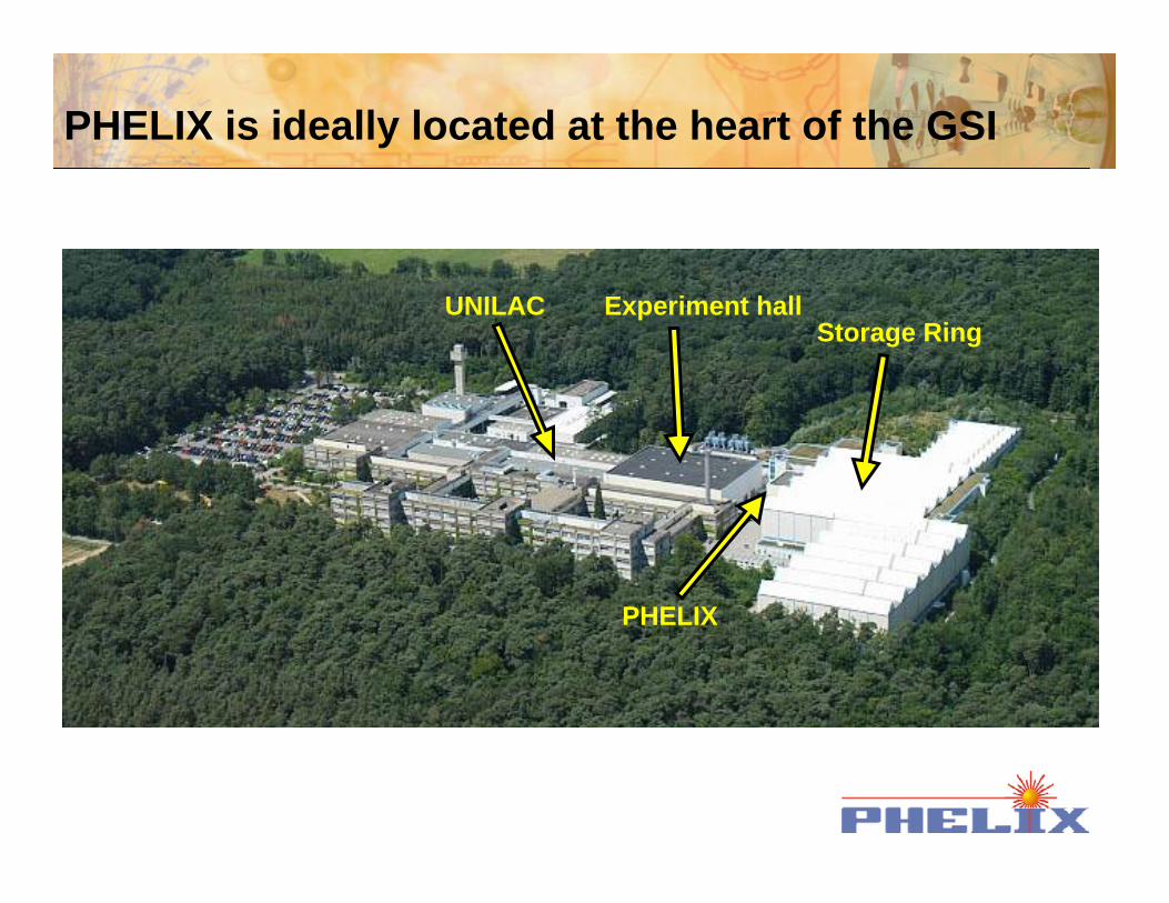
PHELIX is ideally located at the heart of the GSI
UNILAC Experiment hallStorage Ring
PHELIX
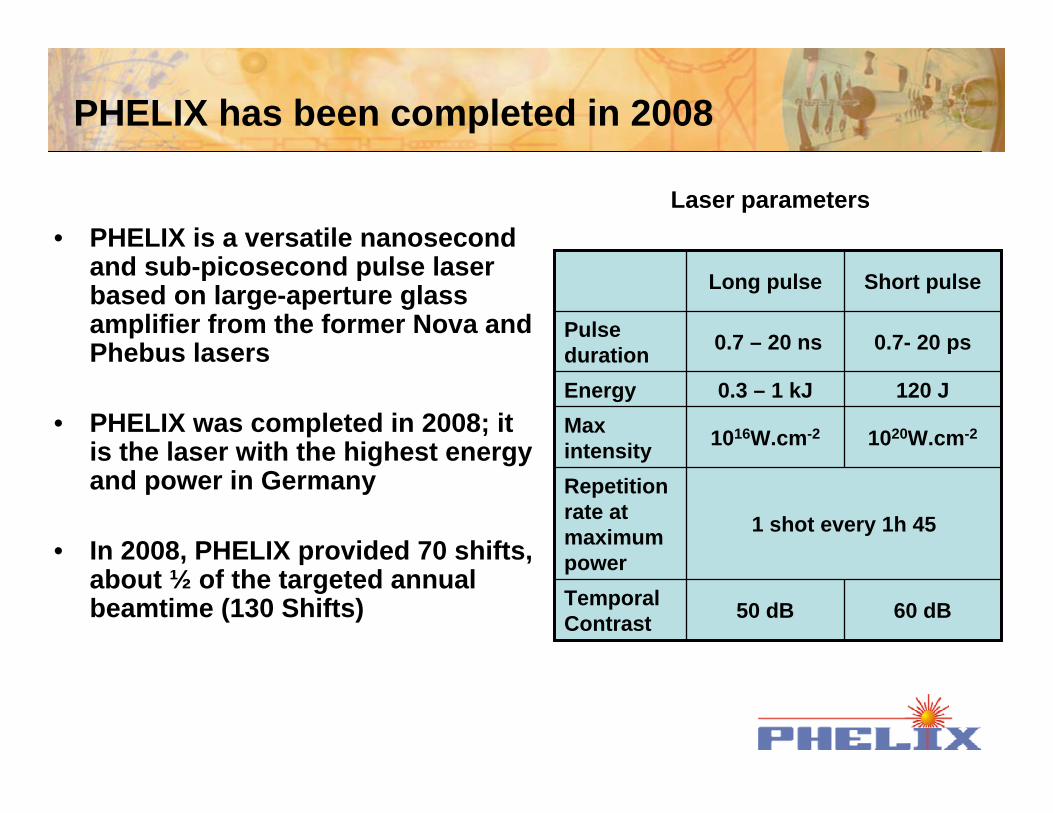
PHELIX has been completed in 2008
• PHELIX is a versatile nanosecond and sub-picosecond pulse laser based on large-aperture glass amplifier from the former Nova and Phebus lasers
• PHELIX was completed in 2008; it is the laser with the highest energy and power in Germany
• In 2008, PHELIX provided 70 shifts, about ½ of the targeted annual beamtime (130 Shifts)
1 shot every 1h 45
Repetition rate at maximum power
1020W.cm-21016W.cm-2Max intensity
120 J0.3 – 1 kJEnergy
0.7- 20 ps0.7 – 20 nsPulse duration
50 dB
Long pulse
60 dBTemporal Contrast
Short pulse
Laser parameters
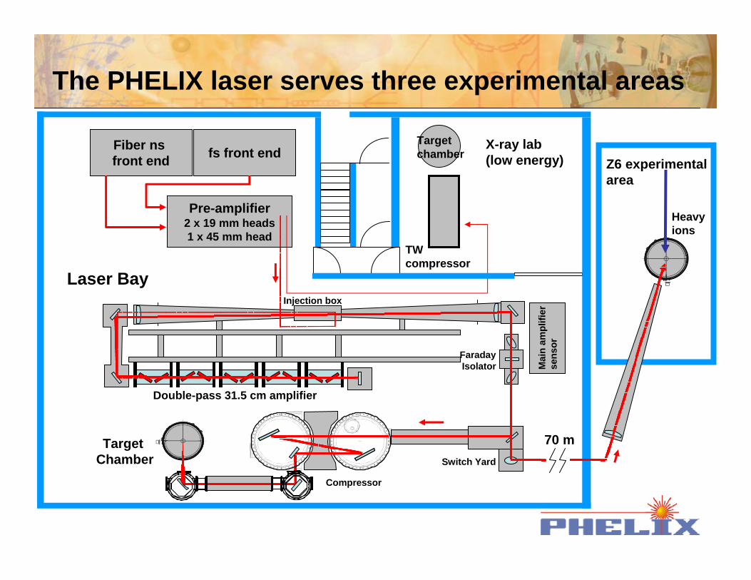
The PHELIX laser serves three experimental areas
Injection box
Mai
n am
plifi
erse
nsor
Faraday Isolator
Switch Yard
Compressor
Target Chamber
fs front endFiber ns front end
Pre-amplifier2 x 19 mm heads1 x 45 mm head
X-ray lab(low energy)
TW compressor
Target chamber
Z6 experimental area
Heavy ions
Laser Bay
Double-pass 31.5 cm amplifier
70 m
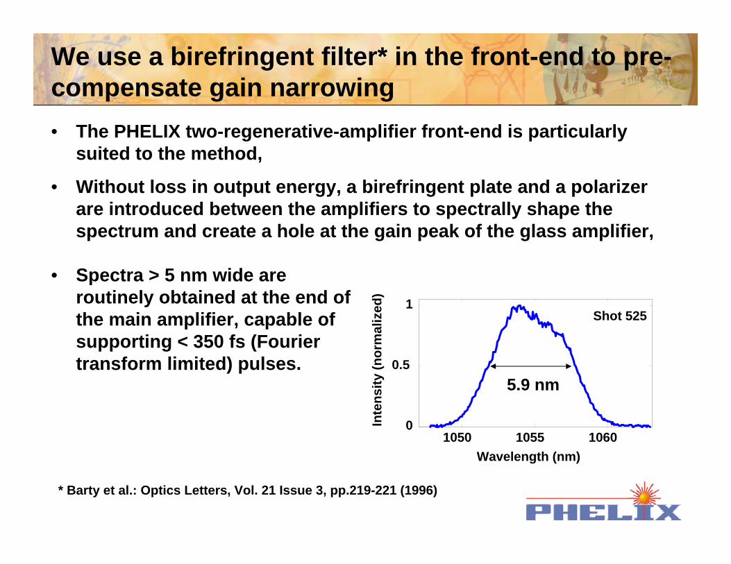
We use a birefringent filter* in the front-end to pre-compensate gain narrowing• The PHELIX two-regenerative-amplifier front-end is particularly
suited to the method,
• Without loss in output energy, a birefringent plate and a polarizer are introduced between the amplifiers to spectrally shape the spectrum and create a hole at the gain peak of the glass amplifier,
1050 1055 10600
0.5
1Shot 525
Wavelength (nm)
Inte
nsity
(nor
mal
ized
)5.9 nm
• Spectra > 5 nm wide are routinely obtained at the end of the main amplifier, capable of supporting < 350 fs (Fourier transform limited) pulses.
* Barty et al.: Optics Letters, Vol. 21 Issue 3, pp.219-221 (1996)
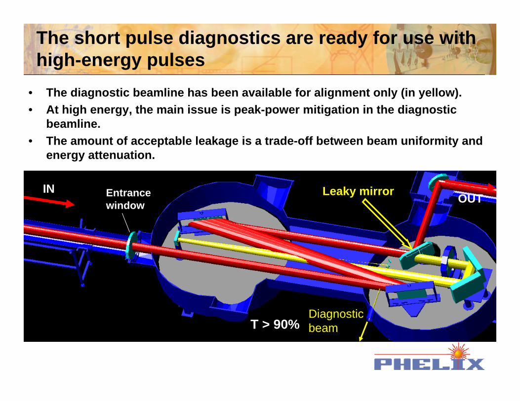
INOUTEntrance
window
T > 90%
The short pulse diagnostics are ready for use with high-energy pulses
• The diagnostic beamline has been available for alignment only (in yellow).• At high energy, the main issue is peak-power mitigation in the diagnostic
beamline. • The amount of acceptable leakage is a trade-off between beam uniformity and
energy attenuation.
Leaky mirror
Diagnostic beam
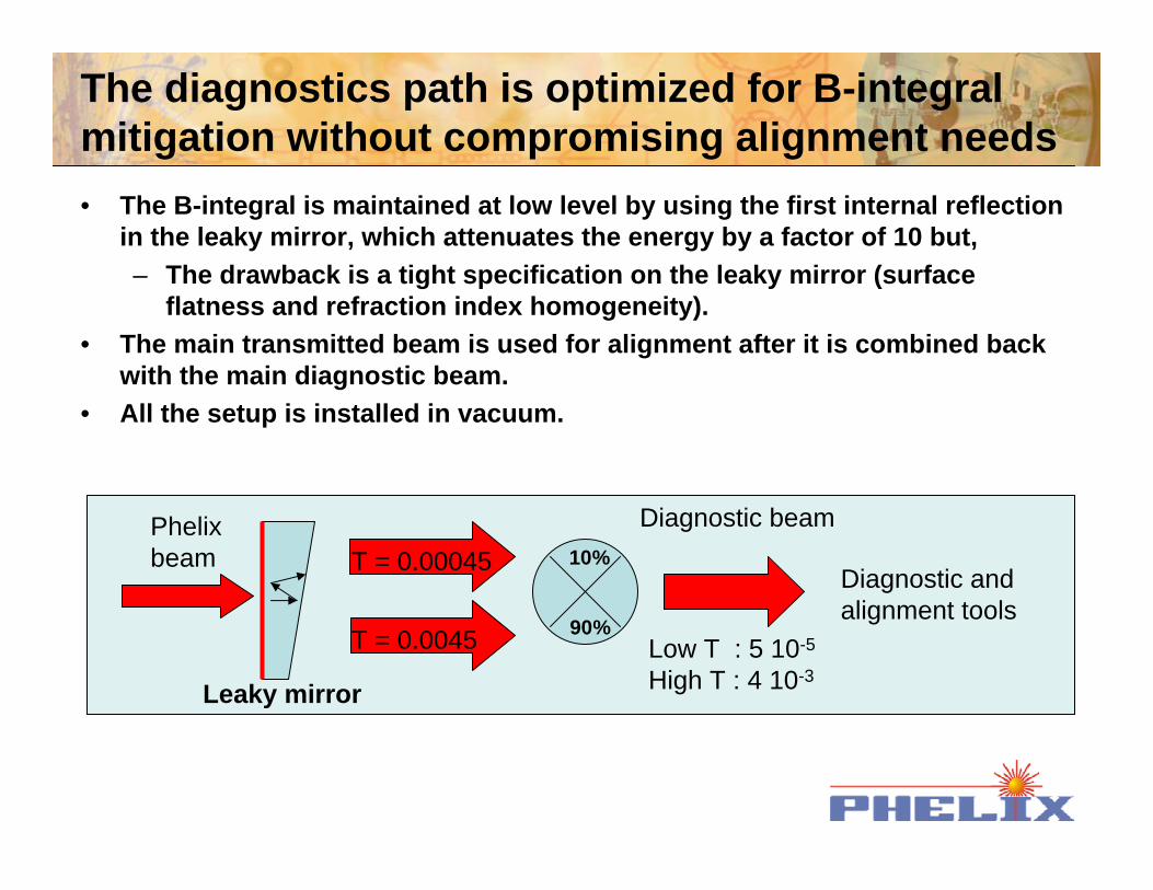
The diagnostics path is optimized for B-integral mitigation without compromising alignment needs
Leaky mirror
Phelix beam
T = 0.0045
T = 0.00045
90%
10%
Diagnostic beam
Diagnostic and alignment tools
Low T : 5 10-5
High T : 4 10-3
• The B-integral is maintained at low level by using the first internal reflection in the leaky mirror, which attenuates the energy by a factor of 10 but,– The drawback is a tight specification on the leaky mirror (surface
flatness and refraction index homogeneity).• The main transmitted beam is used for alignment after it is combined back
with the main diagnostic beam.• All the setup is installed in vacuum.
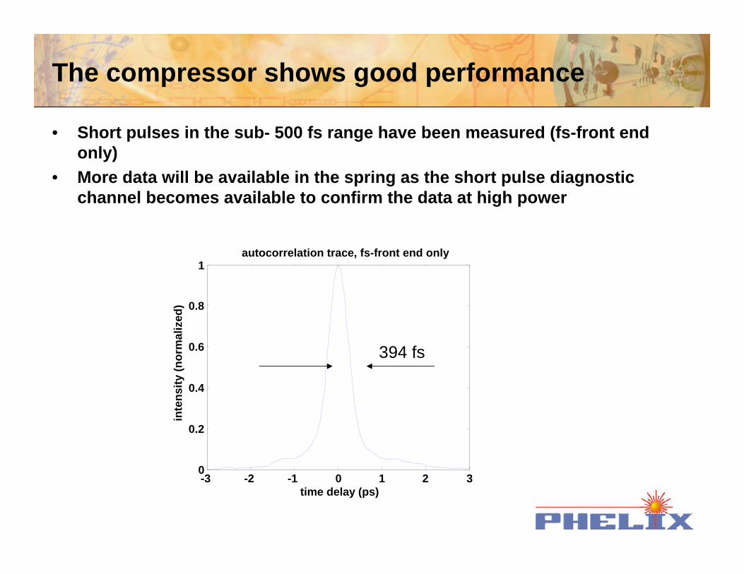
The compressor shows good performance
• Short pulses in the sub- 500 fs range have been measured (fs-front end only)
• More data will be available in the spring as the short pulse diagnostic channel becomes available to confirm the data at high power
-3 -2 -1 0 1 2 30
0.2
0.4
0.6
0.8
1
time delay (ps)
inte
nsity
(nor
mal
ized
)
autocorrelation trace, fs-front end only
394 fs
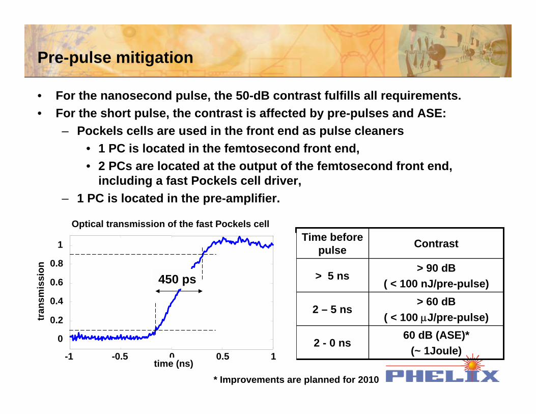
Pre-pulse mitigation
• For the nanosecond pulse, the 50-dB contrast fulfills all requirements.• For the short pulse, the contrast is affected by pre-pulses and ASE:
– Pockels cells are used in the front end as pulse cleaners• 1 PC is located in the femtosecond front end,• 2 PCs are located at the output of the femtosecond front end,
including a fast Pockels cell driver,– 1 PC is located in the pre-amplifier.
60 dB (ASE)*(~ 1Joule)
2 - 0 ns
> 60 dB ( < 100 µJ/pre-pulse)
2 – 5 ns
> 90 dB ( < 100 nJ/pre-pulse)
> 5 ns
Contrast Time before pulse
-1 -0.5 0 0.5 1
0
0.2
0.4
0.6
0.8
1
time (ns)
tran
smis
sion
450 ps
Optical transmission of the fast Pockels cell
* Improvements are planned for 2010
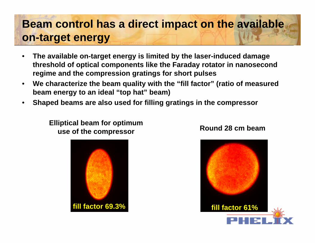
Beam control has a direct impact on the available on-target energy• The available on-target energy is limited by the laser-induced damage
threshold of optical components like the Faraday rotator in nanosecond regime and the compression gratings for short pulses
• We characterize the beam quality with the “fill factor” (ratio of measured beam energy to an ideal “top hat” beam)
• Shaped beams are also used for filling gratings in the compressor
Elliptical beam for optimum use of the compressor
fill factor 69.3%
Round 28 cm beam
fill factor 61%
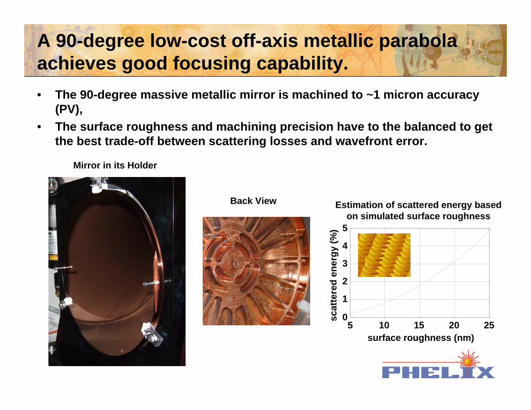
A 90-degree low-cost off-axis metallic parabola achieves good focusing capability.
5 10 15 20 250
1
2
3
4
5
surface roughness (nm)sc
atte
red
ener
gy (%
)
• The 90-degree massive metallic mirror is machined to ~1 micron accuracy(PV),
• The surface roughness and machining precision have to the balanced to get the best trade-off between scattering losses and wavefront error.
Mirror in its Holder
Back View Estimation of scattered energy based on simulated surface roughness
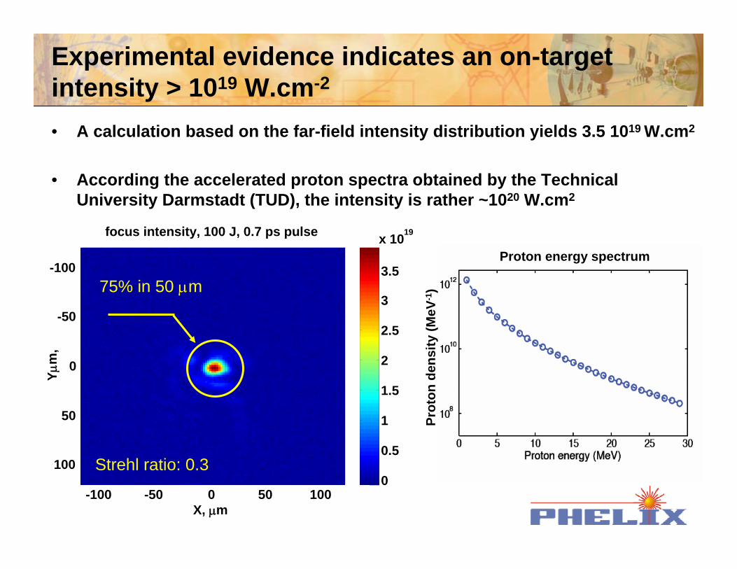
Experimental evidence indicates an on-target intensity > 1019 W.cm-2
• A calculation based on the far-field intensity distribution yields 3.5 1019 W.cm2
• According the accelerated proton spectra obtained by the Technical University Darmstadt (TUD), the intensity is rather ~1020 W.cm2
Prot
on d
ensi
ty (M
eV-1
)
Proton energy spectrum
X, µm
Yµm
,
focus intensity, 100 J, 0.7 ps pulse
-100 -50 0 50 100
-100
-50
0
50
1000
0.5
1
1.5
2
2.5
3
3.5
x 1019
75% in 50 µm
Strehl ratio: 0.3
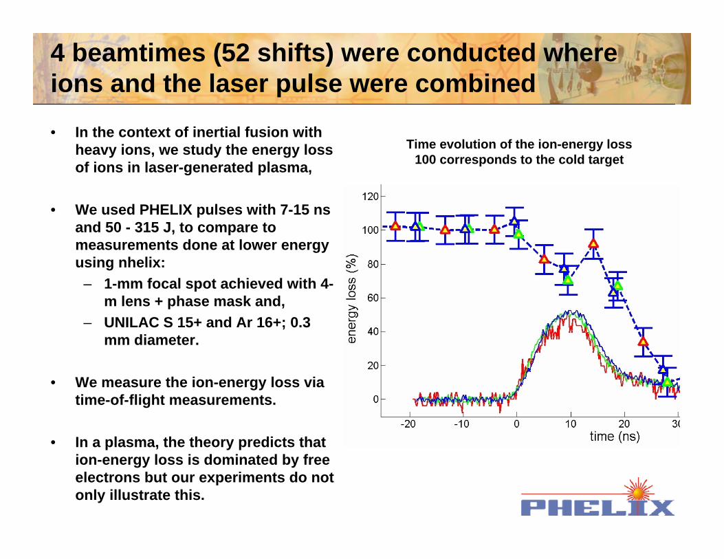
4 beamtimes (52 shifts) were conducted where ions and the laser pulse were combined
• In the context of inertial fusion with heavy ions, we study the energy loss of ions in laser-generated plasma,
• We used PHELIX pulses with 7-15 ns and 50 - 315 J, to compare to measurements done at lower energy using nhelix:
– 1-mm focal spot achieved with 4-m lens + phase mask and,
– UNILAC S 15+ and Ar 16+; 0.3 mm diameter.
• We measure the ion-energy loss via time-of-flight measurements.
• In a plasma, the theory predicts that ion-energy loss is dominated by free electrons but our experiments do not only illustrate this.
Time (ns)
Ener
gylo
ss(%
)
Time evolution of the ion-energy loss100 corresponds to the cold target
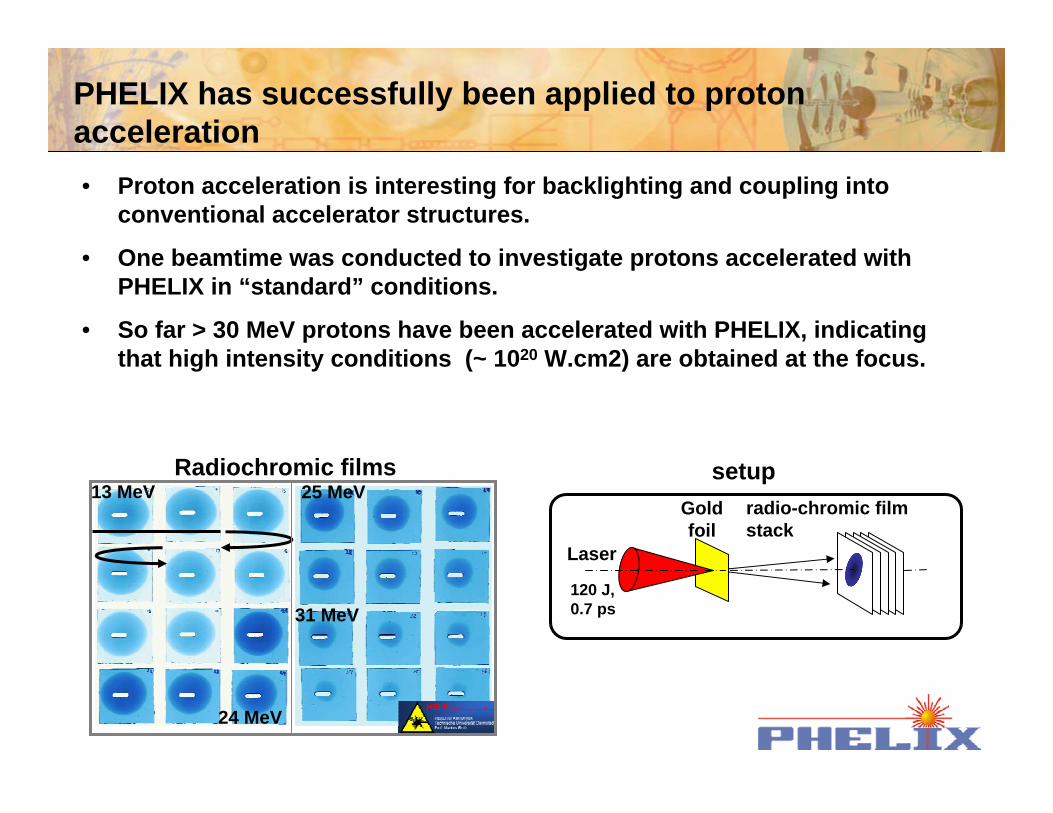
PHELIX has successfully been applied to proton acceleration• Proton acceleration is interesting for backlighting and coupling into
conventional accelerator structures.
• One beamtime was conducted to investigate protons accelerated with PHELIX in “standard” conditions.
• So far > 30 MeV protons have been accelerated with PHELIX, indicating that high intensity conditions (~ 1020 W.cm2) are obtained at the focus.
Gold foil
radio-chromic film stack
Laser
120 J, 0.7 ps
Radiochromic films13 MeV
24 MeV
25 MeV
31 MeV
setup
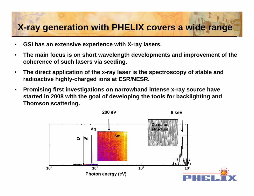
X-ray generation with PHELIX covers a wide range
• GSI has an extensive experience with X-ray lasers.
• The main focus is on short wavelength developments and improvement of the coherence of such lasers via seeding.
• The direct application of the x-ray laser is the spectroscopy of stable and radioactive highly-charged ions at ESR/NESR.
• Promising first investigations on narrowband intense x-ray source have started in 2008 with the goal of developing the tools for backlighting and Thomson scattering.
101 102 103 104
PdSm
Cu nano-structure
200 eV 8 keV
Zr
Ag
Photon energy (eV)
The laser performance will be further enhanced during the next years• Temporal contrast enhancement of the laser pulse and short pulse
capability development at Z6– X-ray generation and particle acceleration will be enhanced after the
temporal contrast is improved by 60 dB – Laser accelerated particles can be best manipulated at Z6 because of
existing capabilities, requiring the building of a short pulse beamline to Z6
• Hohlraum heating at Z6 will be possible thanks to the completion of frequency doubling and tight focusing of the PHELIX beam– Hohraums create homogeneous non-fully-ionized plasma conditions
necessary to support the further studies of stopping power in plasma