Embed Size (px)
Citation preview

BOEING is a trademark of Boeing Management Company.Copyright © 2009 Boeing. All rights reserved.
2008 AIAA Atmospheric and Space Environments
7th AIRA Research Implementation Forum
Current Perspectives on Jet Engine Power Loss in Ice Crystal Conditions: Engine Icing
Jeanne MasonSenior Specialist Engineer - PropulsionBoeing Commercial AirplanesJune 23, 2009Acknowledgements: Walter Strapp, Environment CanadaMatt Grzych, Boeing Philip Chow, Engine Icing Consultant

Copyright © 2009 Boeing. All rights reserved.
Ice Crystal Icing - Definition
Ice crystals (frozen water) associated with convective clouds can form ice in the engine core, where temperatures are initially warmer than freezingIce shedding can cause engine power loss (surge, flameout) and damageHigh Ice Water Content (HIWC) – new term to describe copious quantities of ice crystals in these clouds which cause engine events(Ref: AIAA 2006-206-739 Mason, Strapp & Chow)
Photo: courtesy of Ian McPherson

Copyright © 2009 Boeing. All rights reserved.
What is Ice Crystal Icing?
Frozen ice crystals impinging on a warm surface in the engineSome crystals melt, creating local mixed phase conditionsCrystals impinging on wetted surface stick, cool the surface to 0CIce begins to formAt high altitude, ice can form deep in the engine core
Ice Crystals Encounter Heated Engine Surfaces and Form Ice
An airfoil surface inside the engine core
warm airflow
Supercooled droplet icing
Potential ice particle accretion areas
Copyright © 2009 Boeing. All rights reserved.
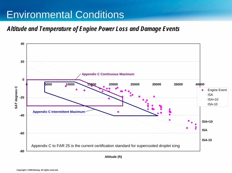
Environmental Conditions
-80
-60
-40
-20
0
20
40
0 5000 10000 15000 20000 25000 30000 35000 40000
Altitude (ft)
SAT
degr
ees
C
Engine EventISAISA+10ISA-10
ISA
ISA-10
ISA+10
Appendix C Continuous Maximum
Appendix C Intermittent Maximum
Appendix C to FAR 25 is the current certification standard for supercooled droplet icing
Altitude and Temperature of Engine Power Loss and Damage Events

Copyright © 2009 Boeing. All rights reserved.
Global View of Engine Power Loss Events
60% of events in the Asia Pacific region – this may be due to the fact that the highest sea surface temperatures are also found in this region

Copyright © 2009 Boeing. All rights reserved.
Scope of the Ice Crystal Icing Problem
Affects multiple models of aircraft and engines (Large transport aircraft and small jet aircraft)
Over 100 power loss events – approximately 1 every 4 monthsTypically 1 in 4 engine power loss events involves multiple engines – large transport events have always restartedApproximately 60 damage events, typically compressor blade tip curl, rarely multiple engines damaged Affects new and old engine designs, new and old enginesData mostly comes from in-service events – pilot reports and digital flight dataThe industry is just beginning to understand this icing phenomenon

Copyright © 2009 Boeing. All rights reserved.
Types of Power Loss Events
Each engine appears to have a different manifestation of ice crystal icingFlight crew recognition and recommended action depends on the eventThere is no single solution for all events
Powerloss Type Description Cockpit Effect
Surge/Stall
Ice shed into compressor drives engine to surge, then stall causes rotor speeds to decay and reducing airflow while combustor remains lit
Thrust loss and High EGT
Flameout Ice shed into the combustor quenches the flame
Thrust loss and all parameters dropping
Engine Damage
Engine compressor blades become damaged as shed ice impacts them
Typically no effect at time of initial damage, damaged blades may fail later causing vibration or engine stall
Copyright © 2009 Boeing. All rights reserved.
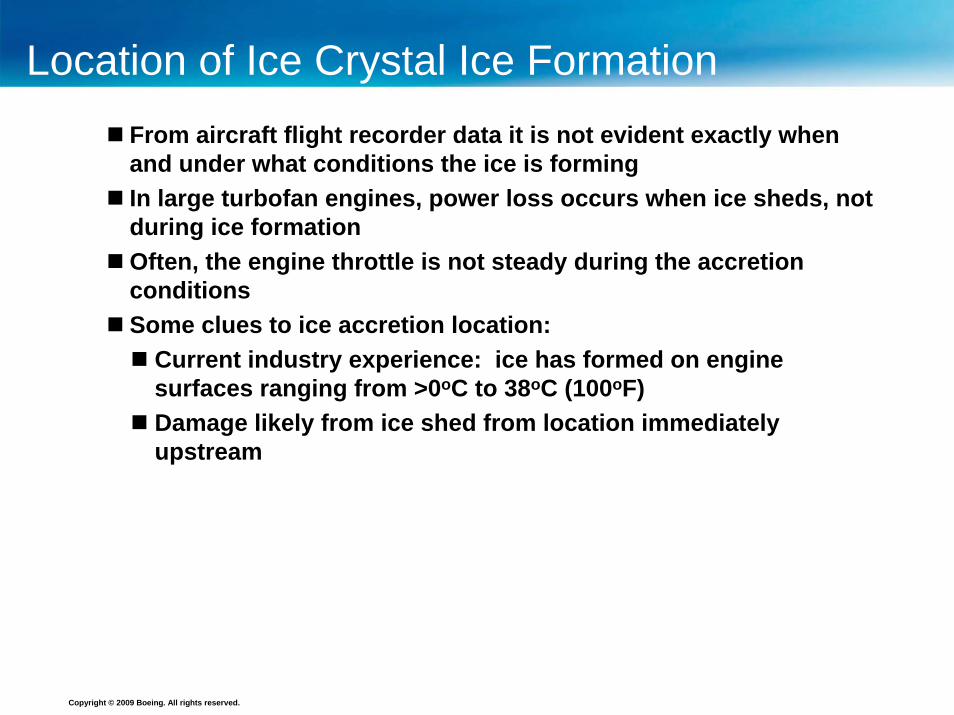
Location of Ice Crystal Ice FormationFrom aircraft flight recorder data it is not evident exactly when and under what conditions the ice is formingIn large turbofan engines, power loss occurs when ice sheds, notduring ice formationOften, the engine throttle is not steady during the accretion conditions Some clues to ice accretion location:
Current industry experience: ice has formed on engine surfaces ranging from >0oC to 38oC (100oF) Damage likely from ice shed from location immediately upstream

Copyright © 2009 Boeing. All rights reserved.
Location of Ice Crystal Ice FormationPinpointing Location of Ice Formation in the Engine
Warmer than freezing on descent, high altitude
sub-freezing

Copyright © 2009 Boeing. All rights reserved.
Pilot Reports Provide Valuable Insight
Events occur with little or no reflectivity at flight level – ice particles are very small & poor reflectors of radar energyWhile avoiding weather radar returns – not flying through heavy storm coresLow to moderate turbulence – low updraft velocitiesNo airframe ice – ice particles hitting airframe do not accretePilots often report heavy rain – ice particles melting on the heated windscreen give the appearance of rainPilots are following standard practices regarding thunderstorm avoidance – the conditions where engine power loss events are occurring have not traditionally been considered a weather concern
Events often occur in conditions the pilots consider benign

Copyright © 2009 Boeing. All rights reserved.
Airframe icing
Convective CloudConvective Cloud
Engine ice crystal icing
Flying in cloud above the freezing level in convective weatherAircraft may already be avoiding flight-level weather radar returnsAircraft is near the deepest part of the cloud (cloud tops can reach the tropopause)
Heavy rain is present below the aircraft, producing yellow and red returns, but few or no returns at flight levelUsing ‘tilt feature’ on radar should identify heavy rain below –
a good indicator that dense ice crystals may exist above
High concentrations of ice crystals
Pilot Recognition of HIWC is a Process of Deduction
Rain
Freezing Level
Radar Representation of Convective CloudRadar Representation of Convective Cloud

Copyright © 2009 Boeing. All rights reserved.
Event Analysis – Where does HIWC occur?
Goal: to understand where, and in what types of cloud high ice water content occursThree areas of focus:
1. Meteorological: satellite images, ground based radar, convective environment
2. Pilot reports: proximity to radar returns, reports of rain, turbulence
3. Total Temperature Sensor Anomaly
Boeing has conducted in-depth analyses of 50 events

Copyright © 2009 Boeing. All rights reserved.Conceptual model cross section
x
z
Freezing Level
HIWC possibleHIWC possible
ActiveConvection
ActiveConvection
Stratiform Region
Stratiform Region
Decaying convection
Tropopause
Safe to fly zoneSafe to fly zone
Developed from event database with ground based radar data Radar data has revealed that reflectivity typically exceeds 30dbz below the aircraft at the time of the engine power loss
A Conceptual Model of HIWC RegionsA Conceptual Model of HIWC Regions
A A
A-A

Copyright © 2009 Boeing. All rights reserved.
Industry Progress - Regulations
Development of Regulatory Requirements:Created Appendix D, an interim icing envelope for Engine Certification FAR Part 33 – similar to Appendix C, built with theory and experimental data (SAE 2007-01-3377 Mazzawy & Strapp)
Developed draft rules for engine and powerplantcertification - part of Supercooled Large Droplet package expected to be published as FAA Notice of Proposed Rulemaking (NPRM) 1st quarter 2010Means of compliance by similarity proposed until technology needs are completed
Industry Committee Activities

Copyright © 2009 Boeing. All rights reserved.
Future Compliance with Federal Aviation Regulations
Compliance with the regulations in future will mean conducting engine testsCurrently specific test points do not exist – need to reflect real life encountersEvent data analysis can help formulate test conditionsHow long do we expose the engine to HIWC?Can the aircraft be exposed during holding?
Event Analysis Provides Information for Future Engine Testing in Ice Crystals

Copyright © 2009 Boeing. All rights reserved.
Industry Progress – Research Needs
Technology Plan developed to address unknowns:1. Improved instrumentation to measure atmosphere 2. Flight trials to characterize atmosphere
(understand particle size, concentration and extent) 3. Fundamental physics of ice accretion and shedding 4. Test methods and facilities Government/Industry partnerships are being created to fund this work
Industry Committee Activities

Copyright © 2009 Boeing. All rights reserved.
Fundamental Physics of Ice Accretion and Shedding - Progress
Boeing and National Research Council of Canada partnered for the first successful rig-based simulation of engine-like conditions January 2009Objectives:
1. Modeled mixed phase ice accretion in both above freezing and below freezing airflow
2. Explored accretion characteristics of various combinations of LWC (liquid water content) and IWC (ice water content)
3. Determined the influence of surface temperature on accretion and the adhesion of the accreted ice
4. Observed the response of embedded metal thermocouples5. Obtained data to understand the process of the ice crystals
impacting the surface and the initiation of accretion
Technology Plan Item 3 - Successful Rig test

Copyright © 2009 Boeing. All rights reserved.
Technology Plan Item 3 - Successful Rig Test
Geometry to simulate engine s-shaped duct with fan frame
Metal surface thermocoupleson leading edge of airfoil
Independently heat controlled endwall
Warm air, frozen ice particles
Simulation of the s-shaped duct between the low and high compressors

Copyright © 2009 Boeing. All rights reserved.
Rig Simulation of Icing in Engine Environment
Local mixed phase conditions must be presentSurface temperature reduction to freezing (0oC) for ice formationObserved ice forming on endwall and stagnation points
General Test Results

Copyright © 2009 Boeing. All rights reserved.
Rig Simulation of Icing in Engine Environment
The airfoil in the model is similar to an engine fan frame – washed by ambient air
The temperature controlled endwall -when not equal to ambient temperature, it had totally different accretion / shed characteristics than the airfoil
Two Different Scenarios for Ice Crystal Accretion and Shedding

Copyright © 2009 Boeing. All rights reserved.
Phantom Camera Images of Ice Impact
Investigated: − onset of ice accretion− how/whether particles
bounce/break on the surface
− where incoming water goes – splash or stick to surface
− how much liquid is present on the surface, and does it splash
− amount of melting of incoming particle
Single ice particle impacting leading edge taken with NASA’s phantom camera

Copyright © 2009 Boeing. All rights reserved.
Overview of Results
Although a simplified model, the rig produced results consistentwith some of our predictions about the ice crystal accretion processIt is the first time that we have a controlled experiment showing that accretion is possible on surfaces warmer than freezing, as measured by thermocouplesThe high speed camera provided insight into the mechanism of initial accretion, and build-upThe experimental data is still being evaluated, and is expected to provide guidance for developing the next set of rig tests Further testing of this nature will be needed to develop parameterizations for all the elements of the icing process

Copyright © 2009 Boeing. All rights reserved.
Impinging ice and waterHeat flux from warm air through blade to ice interface, warming the bond
warm airflowViscous heating
Kinetic heatingHeat of fusion
Evaporation
Convection
Water on the surface of the iceimpinging watersurface melting from warm airflowsplashing, filming
Partly melted ice particle –melting as it travels in heated air, irregular particles with varying drag
Swirl from compressor stages
Erosion from impacting ice
Particle impact –particle and break-up, coefficient of restitution – dependent on amount of water on surface and whether ice has already formed on the surface
Black text represents elements of supercooled droplet accretion
Complex Heat Transfer Problem – Some of the Elements
Impinging water

Copyright © 2009 Boeing. All rights reserved.
Next Steps in Fundamental Physics Research
2nd Boeing/NRC Collaborative Rig Test May 2009 – airfoil at an angle of attackIce Crystal Icing Consortium - cascade test in 2009 (macroscopic processes)Collaborative test on flat plate (microscopic processes of particle bouncing, breakup & splashing)
Technology Plan – Progress on Item 3 Fundamental Physics

Copyright © 2009 Boeing. All rights reserved.
Conclusions
Ice crystal icing conditions continue to cause turbofan engines power loss and damage eventsEvent analysis allows us to provide better information to pilots for weather recognitionData on location of events with respect to reflectivity in the cloud will be valuable to future flight programs and definition of future engine testsProgress is being made towards understanding of the physics of ice crystal accretion and shedding in the engineThere are still many challenges

BOEING is a trademark of Boeing Management Company.Copyright © 2009 Boeing. All rights reserved.