Embed Size (px)
Citation preview
1
Current Status and Challenges of SoC Verification for
Embedded Systems Market
Sep. 18, 2003/ Portland Hilton
Chong-Min Kyung,
KAIST
IEEE International SOC Conference
2
Current Status and Challenges of SoC Verification for
Embedded Systems Market
(요약) 우리나라의 장차 적어도 30년간 산업과 기술에서 SoC 가 갖는 비중은 매우 크다. 내장 시스템 (Embedded System) 을 구성하는핵심 부품인 SoC 칩은 설계보다 검증이 더 큰 비용을 요구할 수 있다. 다른 말로, 광의의 SoC 설계는 검증이 70% 이상을 차지할 수 있다. 이 발표는 최신 SoC 검증의 방법과 장단점과 미래의 도전이 무엇인지에 대하여 생각하기 위한 것이다. TTM (Time-to-market) 이핵심인 SoC market 에서는 설계와 검증의 대상뿐 아니라 과정/수단도 Hardware+Software 로서 Amphibian(수륙양용식) 접근 이 필요하다. SoC 검증을 위한 언어와 표준, Tool/Solution 과 Movement 를소개하면서 우리는 어떻게 해야 소위 신성장 동력이라 회자하는SoC 가 우리 산업에서 booming 할 수 있는지 같이 고민해보자. 이미 강력한 미국, 일본, 유럽 외에 중국, 대만, 인도 등이 강력한 계획과 야심을 가지고 달리는 이 super-dynamic 한 상황에서 말이다.
3
Agenda
Why Verification ?
Verification Alternatives
Languages for System Modeling and Verification
Verification with Progressive Refinement
SoC Verification
Concluding Remarks
4
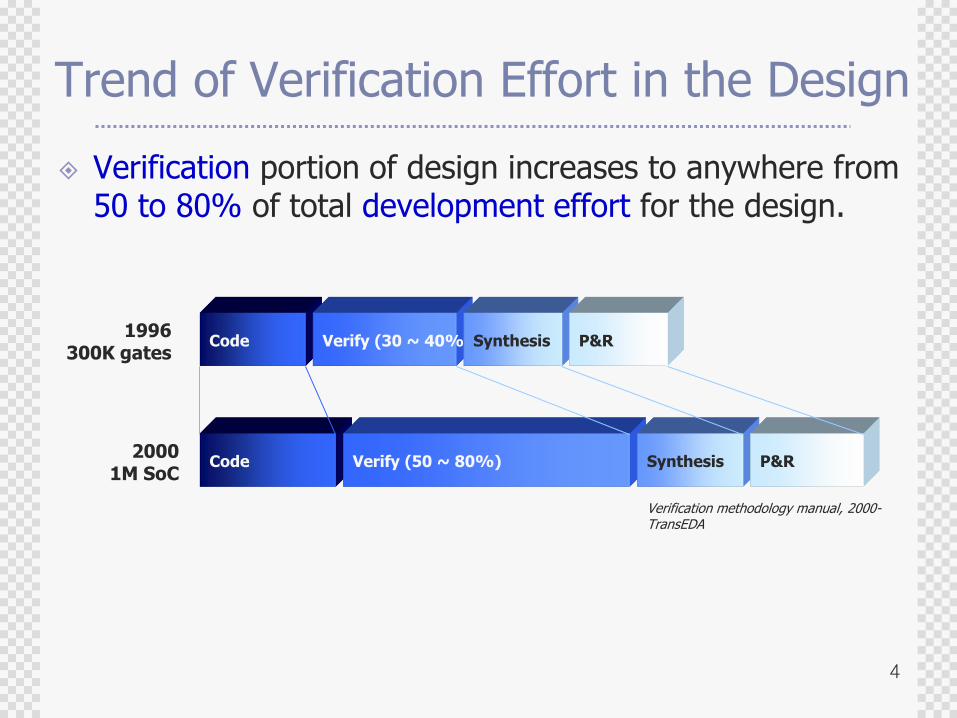
Trend of Verification Effort in the Design
Verification portion of design increases to anywhere from 50 to 80% of total development effort for the design.
Code Verify (30 ~ 40%)Synthesis P&R
Code Verify (50 ~ 80%) Synthesis P&R
1996300K gates
20001M SoC
Verification methodology manual, 2000-TransEDA
5
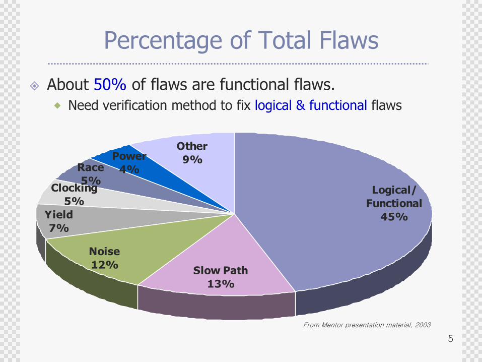
Percentage of Total Flaws
About 50% of flaws are functional flaws.
Need verification method to fix logical & functional flaws
From Mentor presentation material, 2003
Clocking
5%
Race
5%
Power
4%
Other
9%
Yield
7%
Noise
12%Slow Path
13%
Logical/
Functional
45%
6
Another recent independent study showed that more than half of all chips require one or more re-spins,
and that functional errors were found in 74% of these
re-spins.
With increasing chip complexity, this situation could worsen.
Who can afford that with >= 1M Dollar NRE cost?
7
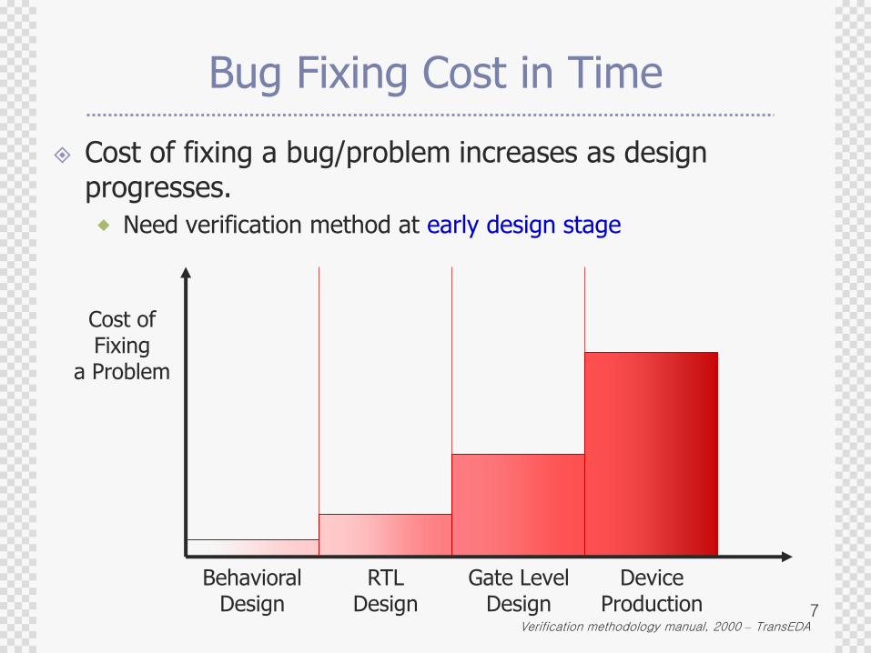
Bug Fixing Cost in Time
Cost of fixing a bug/problem increases as design progresses.
Need verification method at early design stage
Verification methodology manual, 2000 – TransEDA
BehavioralDesign
RTLDesign
Gate LevelDesign
DeviceProduction
Cost ofFixing
a Problem
8
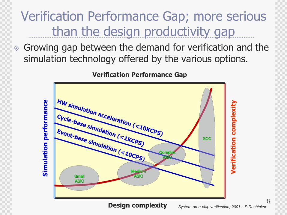
Verification Performance Gap; more serious than the design productivity gap
Growing gap between the demand for verification and the simulation technology offered by the various options.
System-on-a-chip verification, 2001 – P.RashinkarDesign complexity
Sim
ula
tio
n p
erf
orm
an
ce
Ve
rifi
ca
tio
n c
om
ple
xit
y
Verification Performance Gap
SmallASIC
MediumASIC
ComplexASIC
SOC
9
Completion Metrics; How do we know when the verification is done?
Emotionally, or Intuitively;
Out of money? Exhausted?
Competition‟s product is there.
Software people are happy with your hardware.
There have been no bugs reported for two weeks.
More rigorous criteria;
All tests passed
Test Plan Coverage
Functional Coverage
Code Coverage
Bug Rates have flattened toward bottom.
10
Verification Challenges
Specification or Operating Environment is Incomplete/Open-Ended. (Verification metric is never complete like last-minute ECO.)
The Day before Yesterday‟s tool for Today‟s Design.
Design productivity grows faster than Verification productivity.
11
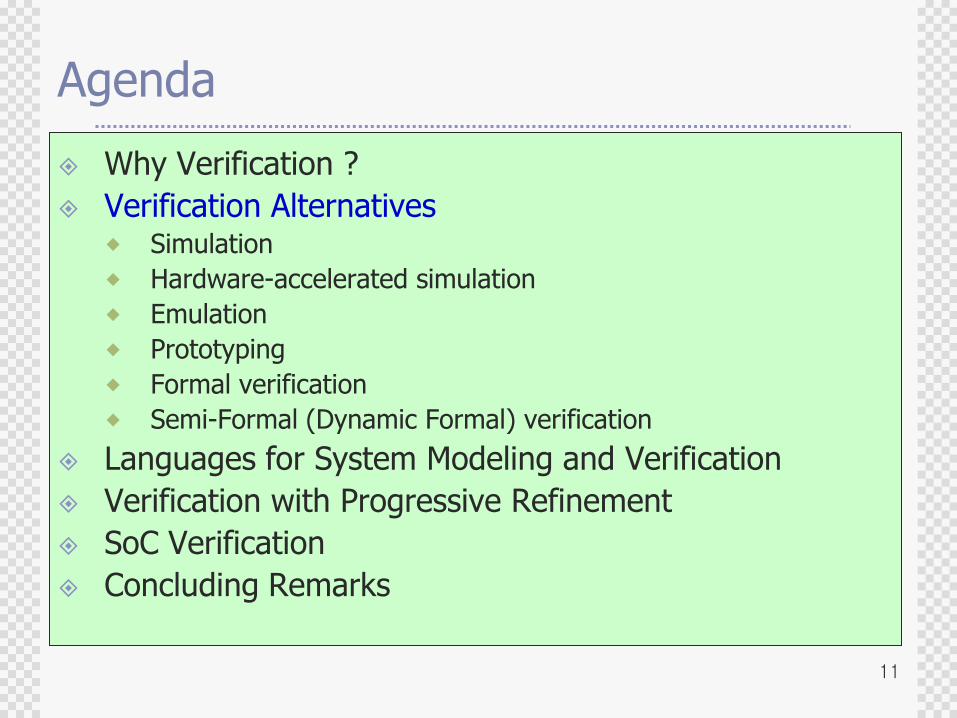
Agenda
Why Verification ?
Verification Alternatives Simulation
Hardware-accelerated simulation
Emulation
Prototyping
Formal verification
Semi-Formal (Dynamic Formal) verification
Languages for System Modeling and Verification
Verification with Progressive Refinement
SoC Verification
Concluding Remarks
12
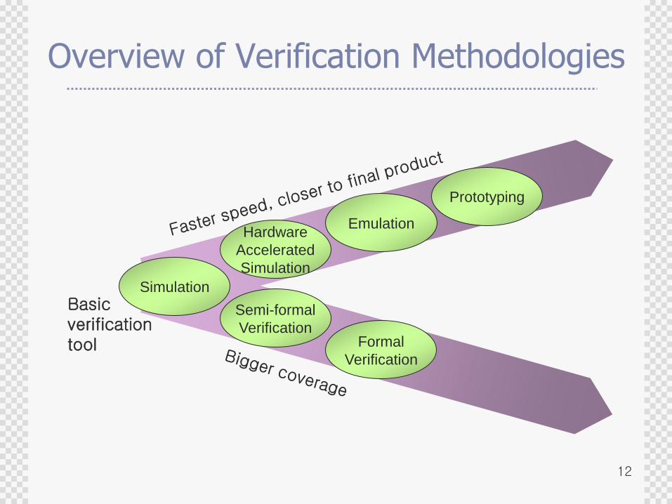
Overview of Verification Methodologies
Simulation
Hardware
Accelerated
Simulation
Emulation
Formal
Verification
Semi-formal
Verification
Prototyping
Basicverificationtool
13
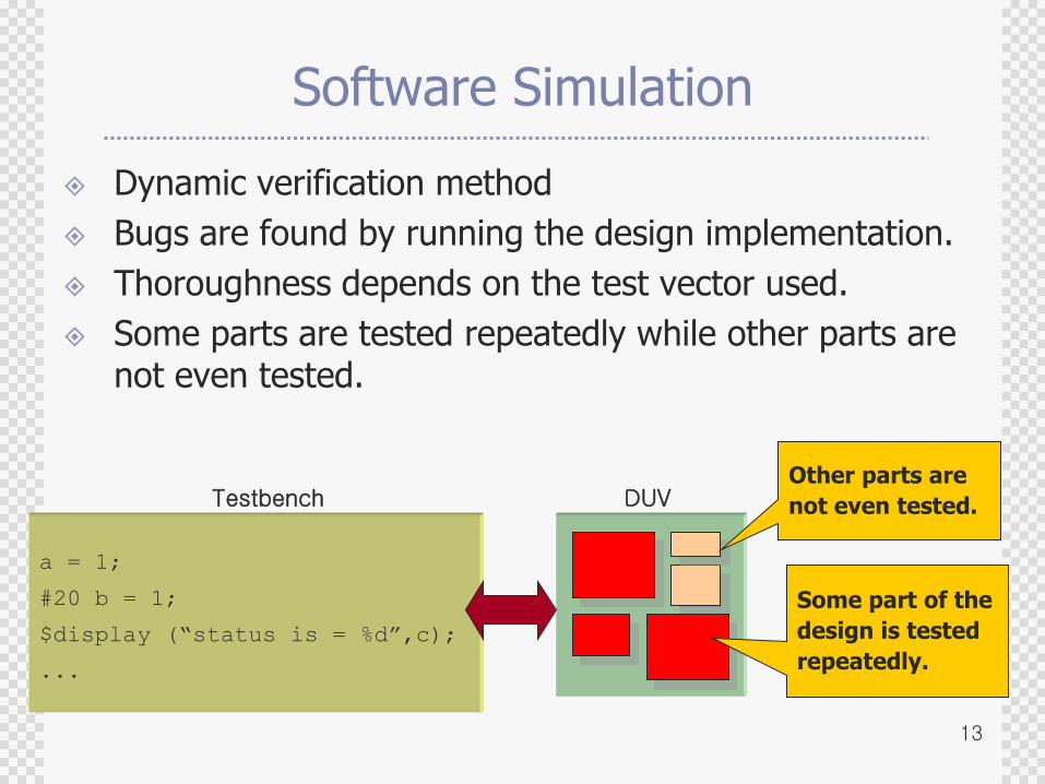
Software Simulation
Dynamic verification method
Bugs are found by running the design implementation.
Thoroughness depends on the test vector used.
Some parts are tested repeatedly while other parts are not even tested.
a = 1;
#20 b = 1;
$display (“status is = %d”,c);
...
Testbench DUV
Some part of the
design is tested
repeatedly.
Other parts are
not even tested.
14
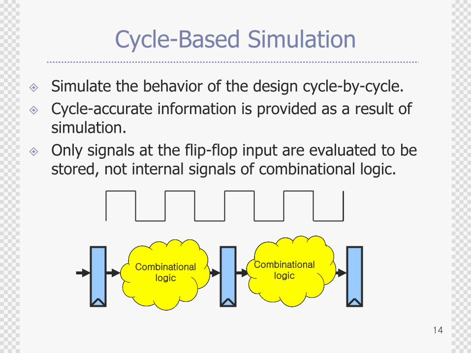
Cycle-Based Simulation
Simulate the behavior of the design cycle-by-cycle.
Cycle-accurate information is provided as a result of simulation.
Only signals at the flip-flop input are evaluated to be stored, not internal signals of combinational logic.
Combinational logic
Combinational logic
Combinational logic
Combinational logic
Combinational logic
Combinational logic
Combinational logic
Combinational logic
Combinational logic
Combinational logic
15
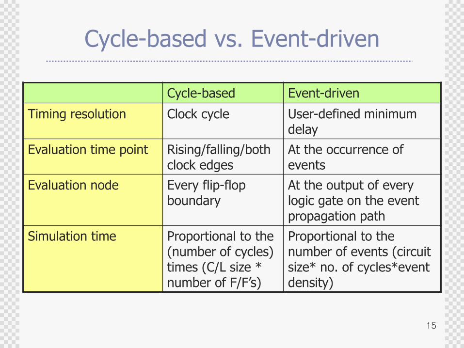
Cycle-based vs. Event-driven
Cycle-based Event-driven
Timing resolution Clock cycle User-defined minimum delay
Evaluation time point Rising/falling/both clock edges
At the occurrence of events
Evaluation node Every flip-flop boundary
At the output of every logic gate on the event propagation path
Simulation time Proportional to the (number of cycles) times (C/L size * number of F/F‟s)
Proportional to the number of events (circuit size* no. of cycles*event density)
16
Software Simulation
Pros
The design size is limited only by the computing resource.
Simulation can be started as soon as the RTL description is finished.
Set-up cost is minimal.
Cons
Slow (~100 cycles/sec) ; Speed gap between the speed of software simulation and real silicon widens. (Simulation speed = size of the circuit simulated / speed of the simulation engine)
The designer does not exactly know how much percentage of the design have been tested.
17
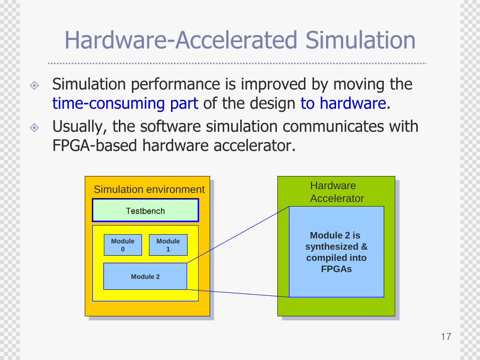
Hardware-Accelerated Simulation
Simulation performance is improved by moving the time-consuming part of the design to hardware.
Usually, the software simulation communicates with FPGA-based hardware accelerator.
Simulation environment
Testbench
Module
0
Module
1
Module 2
Hardware
Accelerator
Module 2 is
synthesized &
compiled into
FPGAs
18
Hardware-Accelerated Simulation
Pros
Fast (100K cycles/sec)
Cheaper than hardware emulation
Debugging is easier as the circuit structure is unchanged.
Not an Overhead : Deployed as a step stone in the gradual refinement
Cons (Obstacles to overcome)
Set-up time overhead to map RTL design into the hardware can be substantial.
SW-HW communication speed can degrade the performance.
Debugging of signals within the hardware can be difficult.
19
Hardware-Accelerated Simulation
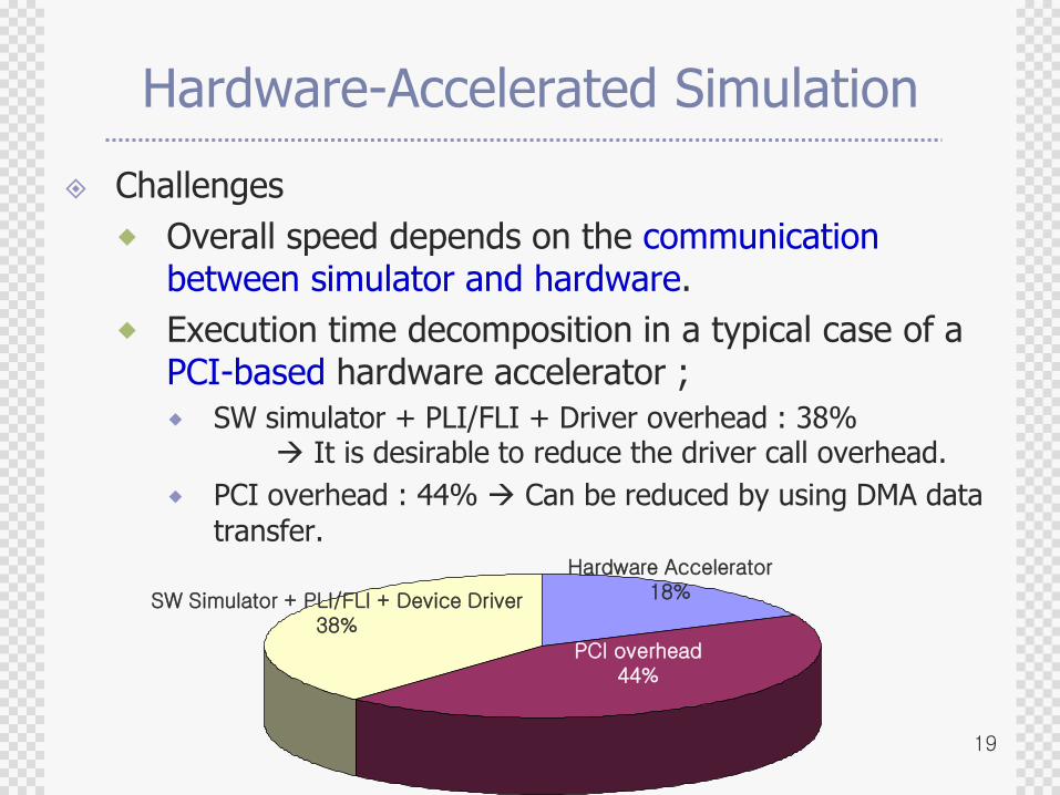
Challenges
Overall speed depends on the communication between simulator and hardware.
Execution time decomposition in a typical case of a PCI-based hardware accelerator ;
SW simulator + PLI/FLI + Driver overhead : 38% It is desirable to reduce the driver call overhead.
PCI overhead : 44% Can be reduced by using DMA data
transfer.
SW Simulator + PLI/FLI + Device Driver38%
Hardware Accelerator18%
PCI overhead44%
20
Emulation
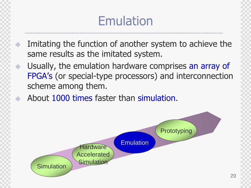
Imitating the function of another system to achieve the same results as the imitated system.
Usually, the emulation hardware comprises an array of FPGA‟s (or special-type processors) and interconnection scheme among them.
About 1000 times faster than simulation.
Simulation
Hardware
Accelerated
Simulation
Emulation
Prototyping
21
Emulation
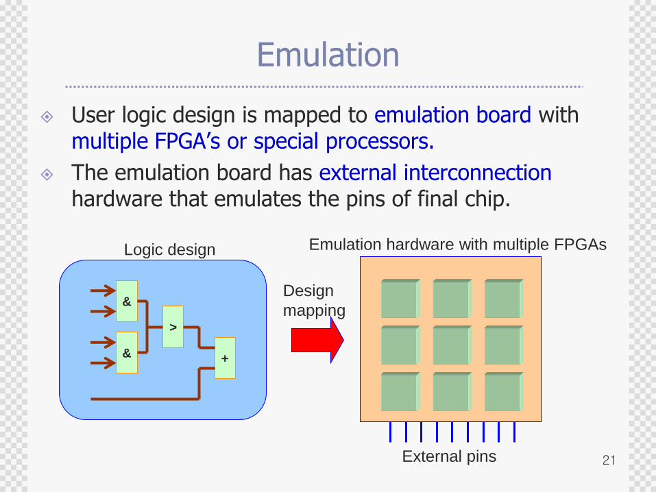
User logic design is mapped to emulation board with multiple FPGA‟s or special processors.
The emulation board has external interconnectionhardware that emulates the pins of final chip.
&
&
>
+
Logic design Emulation hardware with multiple FPGAs
Design
mapping
External pins
22
Emulation
Pros
Fast (500K cycles/sec)
Verification on real target system.
Cons
Setup time overhead to map RTL design into hardware is very high.
Many FPGA‟s + resources for debugging high cost
Circuit partitioning algorithm and interconnectionarchitecture limit the usable gate count.
23
General Architecture of Emulation Systems
FPGA 0 FPGA 1
FPGA 2 FPGA 3
Crossbar(Switch)
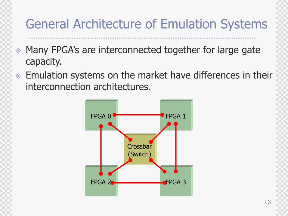
Many FPGA‟s are interconnected together for large gate capacity.
Emulation systems on the market have differences in their interconnection architectures.
24
Emulation
Challenges
Efficient interconnection architecture and Hardware Mapping efficiency for Speed and Cost
RTL debugging facility with reasonable amount of resource
Efficient partitioning algorithm for any given interconnection architecture
Reducing development time (to take advantage of more recent FPGA‟s)
25
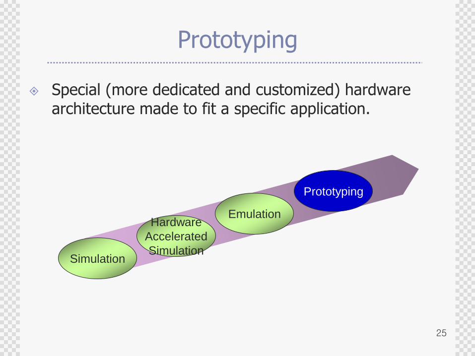
Prototyping
Special (more dedicated and customized) hardware architecture made to fit a specific application.
Simulation
Hardware
Accelerated
Simulation
Emulation
Prototyping
26
Prototyping
Pros
Higher (than emulation) clock rate (over 1M cycles/sec) due to specific design of prototyping board.
Components as well as the wiring can be customized for the corresponding application.
Can be carried along. (Hardware Emulation? Forget it!)
Cons
Not flexible for design change
(Every new prototype requires a new board architecture. / Even a small change requires a new PCB.)
27
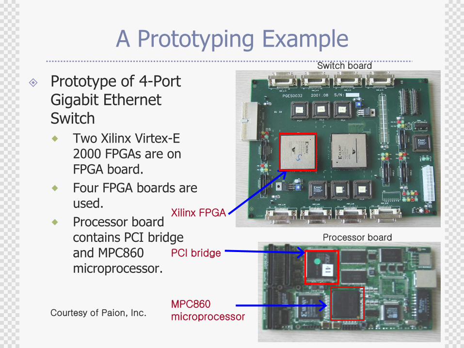
A Prototyping Example
Prototype of 4-Port Gigabit Ethernet Switch
Two Xilinx Virtex-E 2000 FPGAs are on FPGA board.
Four FPGA boards are used.
Processor board contains PCI bridge and MPC860 microprocessor.
PCI bridge
MPC860microprocessor
Xilinx FPGA
Switch board
Processor board
Courtesy of Paion, Inc.
28
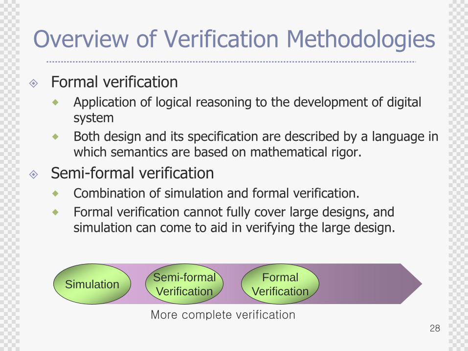
Overview of Verification Methodologies
Formal verification
Application of logical reasoning to the development of digital system
Both design and its specification are described by a language in which semantics are based on mathematical rigor.
Semi-formal verification
Combination of simulation and formal verification.
Formal verification cannot fully cover large designs, and simulation can come to aid in verifying the large design.
SimulationFormal
Verification
Semi-formal
Verification
More complete verification
29
Formal Verification
Objective
Check properties of model with all possible conditions
Pros
Assures 100% coverage.
Fast.
Cons
Works only for small-size finite state systems.
Uncomfortable due to culture difference (E.g., engineers are not familiar with the use of temporal logic used for “property” description in Model Checking)
30
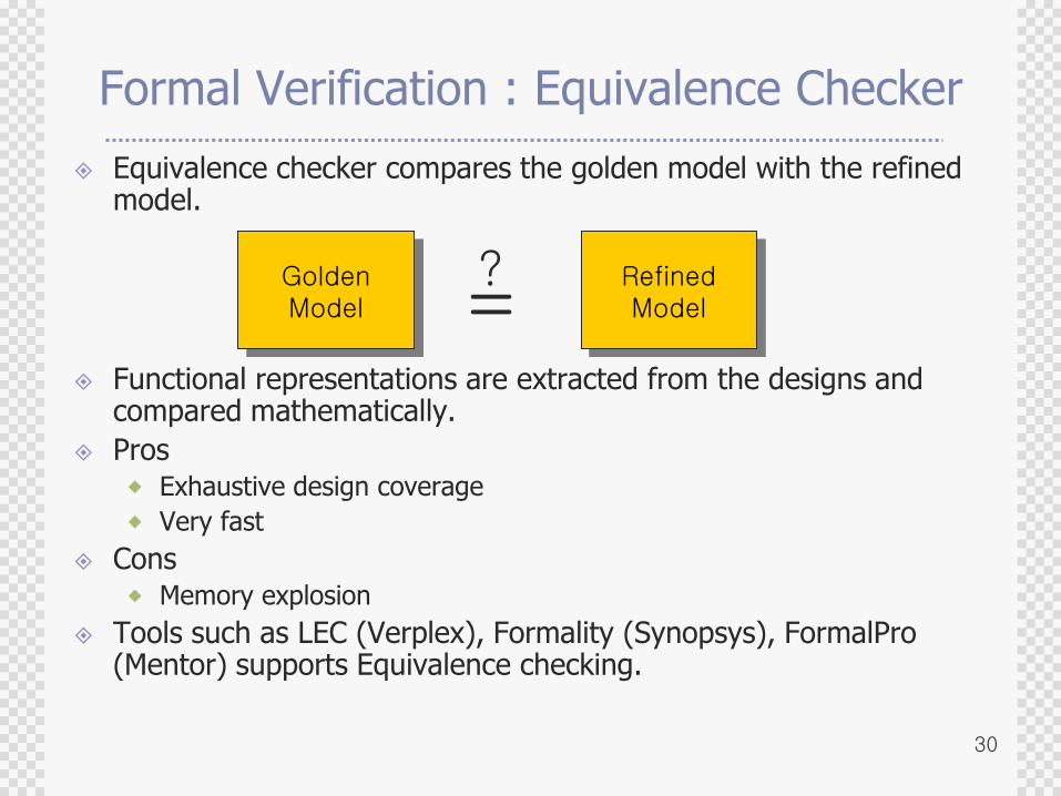
Formal Verification : Equivalence Checker
Equivalence checker compares the golden model with the refined model.
Functional representations are extracted from the designs and compared mathematically.
Pros Exhaustive design coverage
Very fast
Cons Memory explosion
Tools such as LEC (Verplex), Formality (Synopsys), FormalPro (Mentor) supports Equivalence checking.
GoldenModel
RefinedModel=
?
31
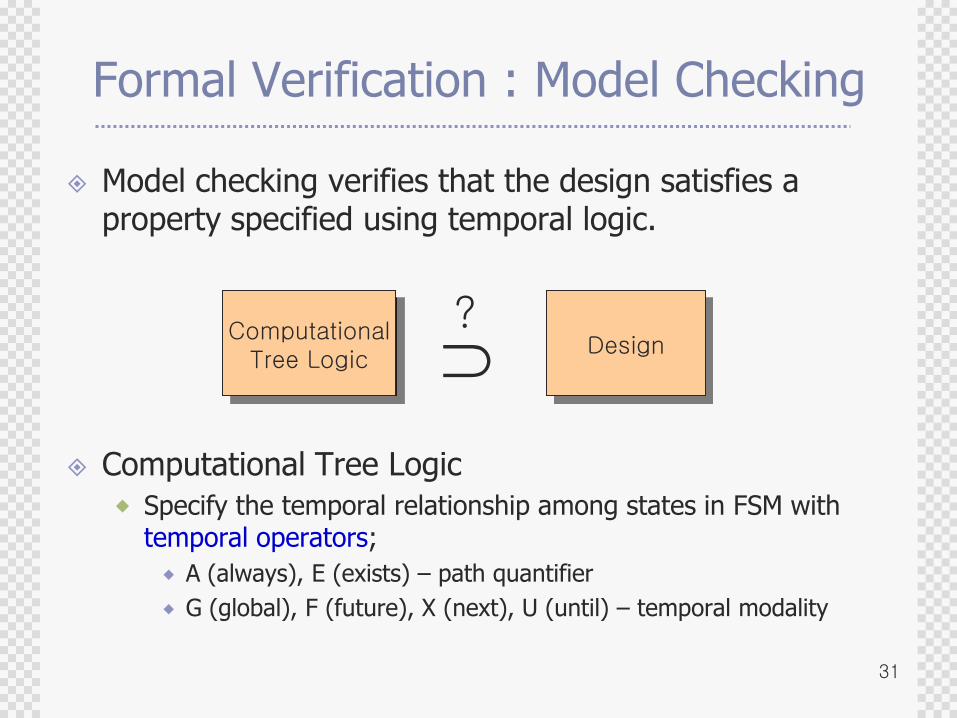
Formal Verification : Model Checking
Model checking verifies that the design satisfies a property specified using temporal logic.
Computational Tree Logic
Specify the temporal relationship among states in FSM with temporal operators;
A (always), E (exists) – path quantifier
G (global), F (future), X (next), U (until) – temporal modality
ComputationalTree Logic
Design?
32
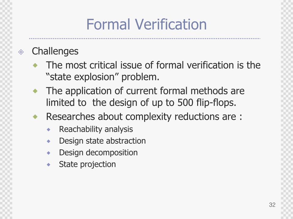
Formal Verification
Challenges
The most critical issue of formal verification is the “state explosion” problem.
The application of current formal methods are limited to the design of up to 500 flip-flops.
Researches about complexity reductions are :
Reachability analysis
Design state abstraction
Design decomposition
State projection
33
Semi-Formal Verification - Assertion
Assertion-based verification (ABV)
“Assertion” is a statement on the intended behavior of a design.
The purpose of assertion is to ensure consistency between the designer‟s intention and the implementation.
Key features of assertions
1. Error detection : If the assertion is violated, it is detected by the simulator.
2. Error isolation : The signals related to the violated assertion are identified.
3. Error notification : The source of error is reported to the user.
34
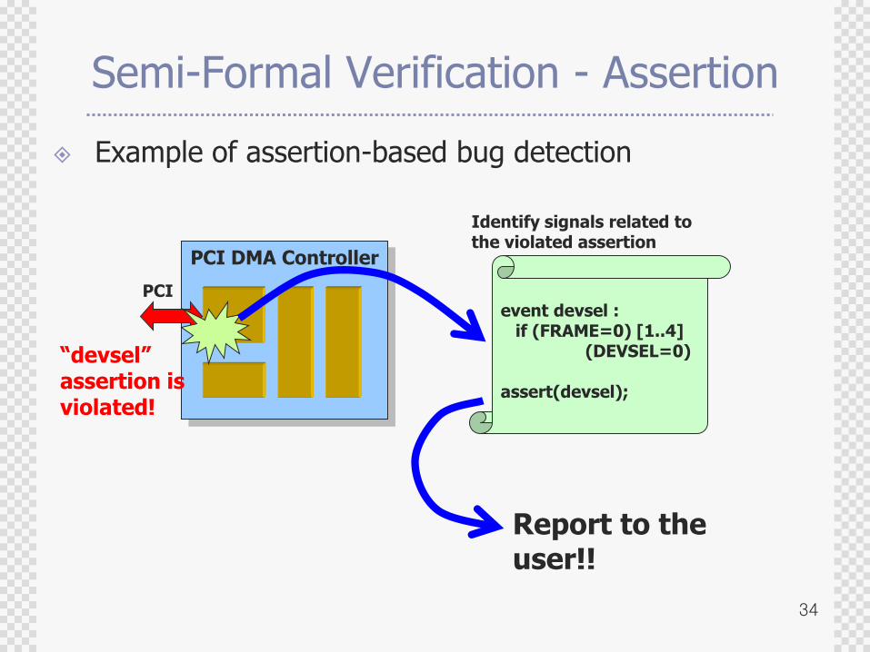
Semi-Formal Verification - Assertion
Example of assertion-based bug detection
PCI DMA Controller
PCIevent devsel :
if (FRAME=0) [1..4] (DEVSEL=0)
assert(devsel);
Identify signals related to the violated assertion
“devsel” assertion is violated!
Report to the user!!
35
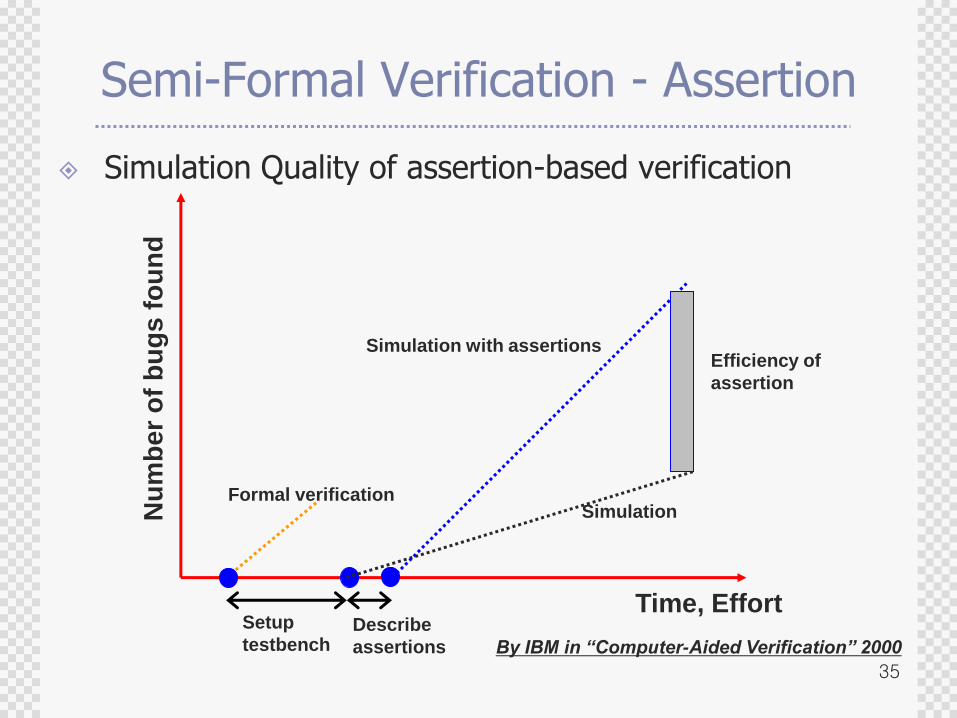
Semi-Formal Verification - Assertion
Simulation Quality of assertion-based verificationN
um
be
r o
f b
ug
s f
ou
nd
Time, EffortSetup
testbenchDescribe
assertions
Formal verificationSimulation
Simulation with assertionsEfficiency of
assertion
By IBM in “Computer-Aided Verification” 2000
36
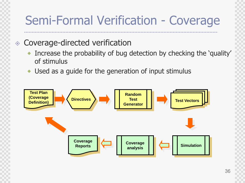
Semi-Formal Verification - Coverage
Coverage-directed verification
Increase the probability of bug detection by checking the „quality‟ of stimulus
Used as a guide for the generation of input stimulus
Test Plan
(Coverage
Definition)Directives
Random
Test
GeneratorTest Vectors
SimulationCoverage
analysis
Coverage
Reports
37
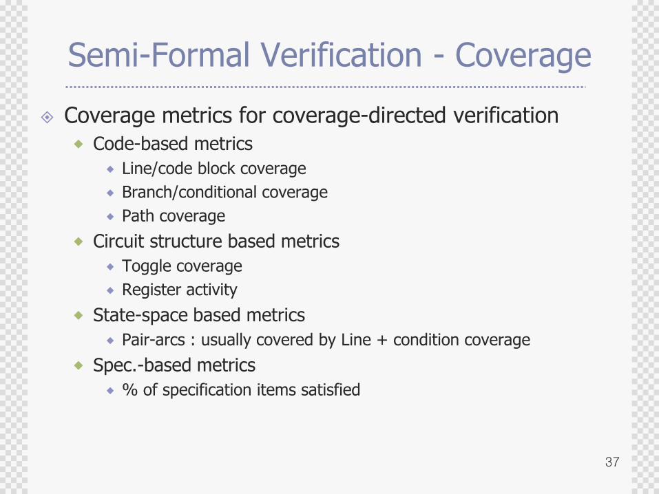
Semi-Formal Verification - Coverage
Coverage metrics for coverage-directed verification
Code-based metrics
Line/code block coverage
Branch/conditional coverage
Path coverage
Circuit structure based metrics
Toggle coverage
Register activity
State-space based metrics
Pair-arcs : usually covered by Line + condition coverage
Spec.-based metrics
% of specification items satisfied

38
Semi-Formal Verification - Coverage
Coverage Checking tools
VeriCover (Veritools)
SureCov (Verisity)
Coverscan (Cadence)
HDLScore, VeriCov (Summit Design)
HDLCover, VeriSure (TransEDA)
Polaris (Synopsys)
Covermeter (Synopsys)
39
Semi-Formal Verification
Pros
Designer can measure the coverage of the test environment as the formal properties are checked during simulation.
Cons
The simulation speed is degraded as the properties are checked during simulation.
Challenges
There is no unified testbench description method.
It is difficult to guide the direction of test vectors to increase the coverage of the design.
Development of more efficient coverage metric to represent the behavior of the design.
40
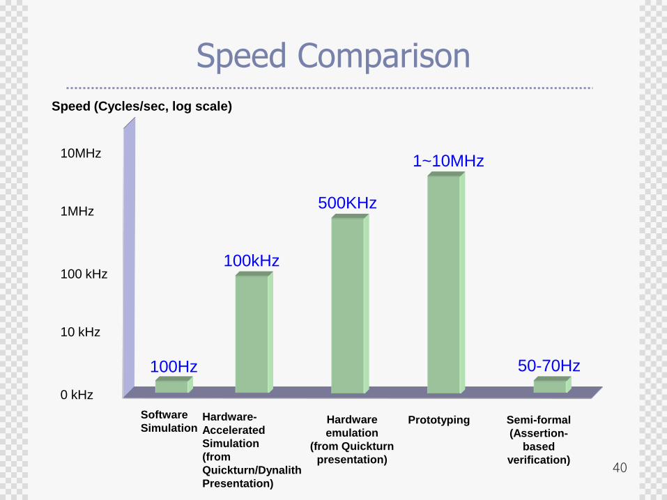
Speed Comparison
0 kHz
Software
Simulation
10 kHz
1MHz
Hardware-
Accelerated
Simulation
(from
Quickturn/Dynalith
Presentation)
Hardware
emulation
(from Quickturn
presentation)
100kHz
500KHz
100Hz
100 kHz
Speed (Cycles/sec, log scale)
10MHz1~10MHz
Prototyping Semi-formal
(Assertion-
based
verification)
50-70Hz
41
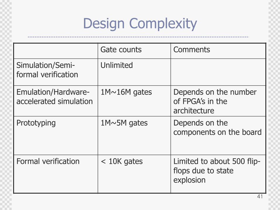
Design Complexity
Gate counts Comments
Simulation/Semi-formal verification
Unlimited
Emulation/Hardware-accelerated simulation
1M~16M gates Depends on the number of FPGA‟s in the architecture
Prototyping 1M~5M gates Depends on the components on the board
Formal verification < 10K gates Limited to about 500 flip-flops due to state explosion
42
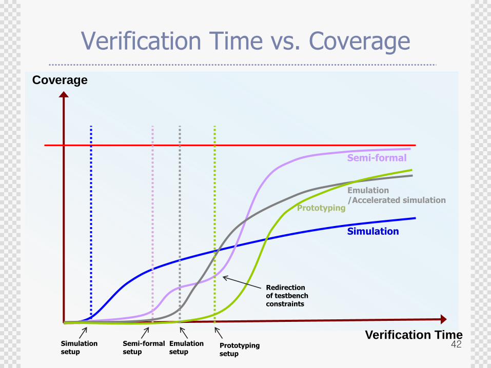
Verification Time vs. Coverage
Coverage
Verification Time
Simulation
Semi-formal
Prototyping
Emulation/Accelerated simulation
Simulation setup
Semi-formal setup
Emulation setup
Prototyping setup
Redirection of testbench constraints
43
Agenda
Why Verification ?
Verification Alternatives
Languages for System Modeling and Verification
System modeling languages
Testbench automation & Assertion languages
Verification with Progressive Refinement
SoC Verification
Concluding Remarks
44
Accellera
Formed in 2000 through the unification of Open Verilog International and VHDL International to focus on identifying new standards, development of standards and formats, and to foster the adoption of new methodologies.
45
Accellera
Three different ways of specifying Assertions in Verilog designs;
OVL (Open Verification Library)
PSL (Property Specification Language)
Native assertion construct in System Verilog
46
ACCELLERA APPROVES FOUR NEW DESIGN VERIFICATION STANDARDS
June 2, 2003 - Accellera, the electronics industry organization focused on language-based electronic design standards approved four new standards for language-based design verification; Property Specification Language (PSL) 1.01, Standard Co-Emulation Application Programming Interface(SCE-API) 1.0, SystemVerilog 3.1 and Verilog-AMS2.1.
47
Accellera's PSL (Property Specification Language)
Gives the design architect a standard means of specifying design properties using a concise syntax with clearly defined formal semantics.
Enables RTL implementer to capture design intent in a verifiable form, while enabling verification engineer to validate that the implementation satisfies its specification with dynamic (that is, simulation) and static (that is, formal) verification.
48
SCE(Standard Co-Emulation Interface)-API
SCE-API standard defines a high-speed, asynchronous, transaction-level interface between simulators or testbenches and hardware-assisted solutions such as emulation or rapid prototypes.
49
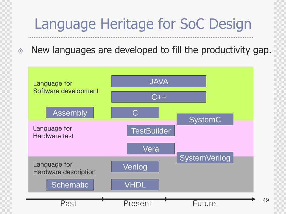
Language Heritage for SoC Design
New languages are developed to fill the productivity gap.
Verilog
VHDL
C
C++
JAVA
AssemblySystemC
SystemVerilogVera
TestBuilder
Language forSoftware development
Language forHardware test
Language forHardware description
Schematic
Past Present Future
50
SystemC
SystemC is a modeling platform consisting of
A set of C++ class library,
Including a simulation kernel that supports hardware modeling concepts at the system level, behavioral level and register transfer level.
SystemC enables us to effectively create
A cycle-accurate model of
Software algorithm,
Hardware architecture, and
Interfaces of System-on-a-Chip.
Program in SystemC can be
An executable specification of the system.
51
SystemC
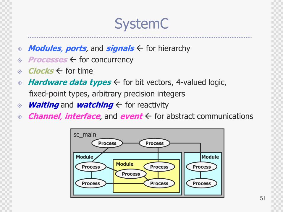
Modules, ports, and signals for hierarchy
Processes for concurrency
Clocks for time
Hardware data types for bit vectors, 4-valued logic,
fixed-point types, arbitrary precision integers
Waiting and watching for reactivity
Channel, interface, and event for abstract communications
sc_main
Module
Module
Process
Process
ProcessProcess
Process
Process Process
Module
Process
Process
52
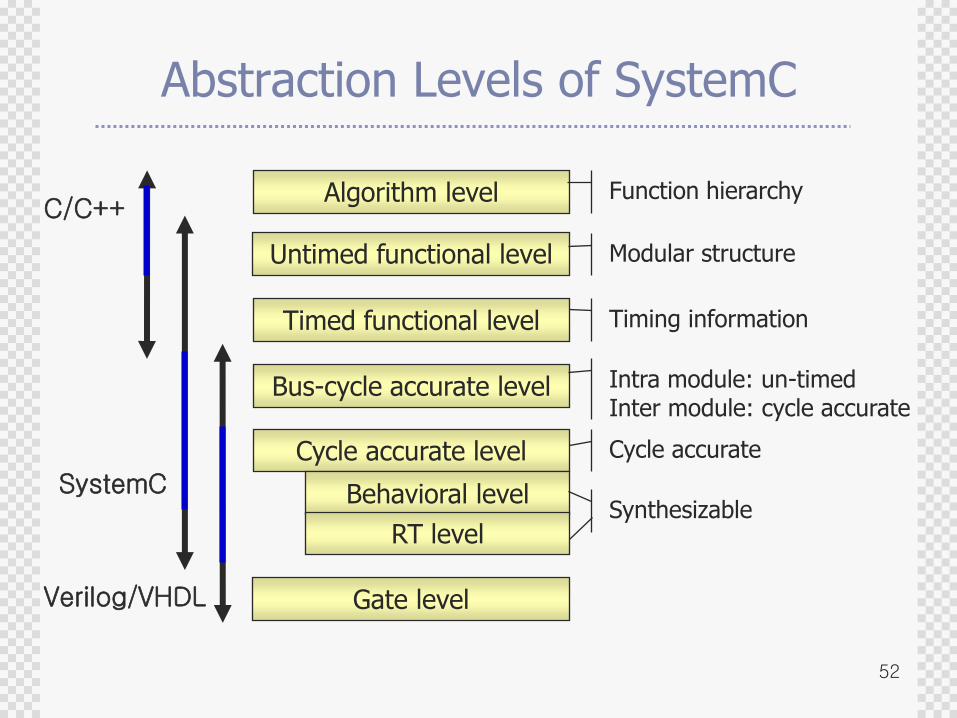
Abstraction Levels of SystemC
Algorithm level
Untimed functional level
Timed functional level
Bus-cycle accurate level
Cycle accurate level
Behavioral level
RT level
C/C++
SystemC
Function hierarchy
Modular structure
Timing information
Intra module: un-timedInter module: cycle accurate
Cycle accurate
Synthesizable
Gate levelVerilog/VHDL
53
Test-bench automation
Why is test-bench automation required?
Test-bench for IP can be more complex than the IP itself.
Manual description of the test-bench is a time-consuming job.
Simulating the whole test-bench in HDL yields excessive verification time.
Players
TestBuilder (Cadence)
Closer to C, integrated to SystemC
VERA (Synopsys)
Closer to Verilog, integrated to SystemVerilog
54
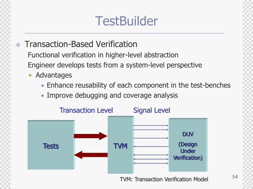
TestBuilder
Transaction-Based Verification
Functional verification in higher-level abstraction
Engineer develops tests from a system-level perspective
Advantages
Enhance reusability of each component in the test-benches
Improve debugging and coverage analysis
DUV
(Design Under
Verification)
TVMTests
Signal LevelTransaction Level
TVM: Transaction Verification Model
55
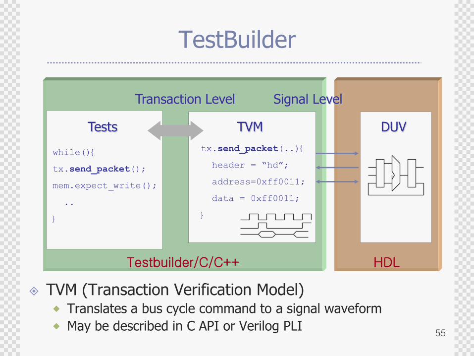
Testbuilder/C/C++ HDL
TestBuilder
Signal LevelTransaction Level
Tests TVM DUV
while(){
tx.send_packet();
mem.expect_write();
..
}
tx.send_packet(..){
header = “hd”;
address=0xff0011;
data = 0xff0011;
}
TVM (Transaction Verification Model) Translates a bus cycle command to a signal waveform
May be described in C API or Verilog PLI
56
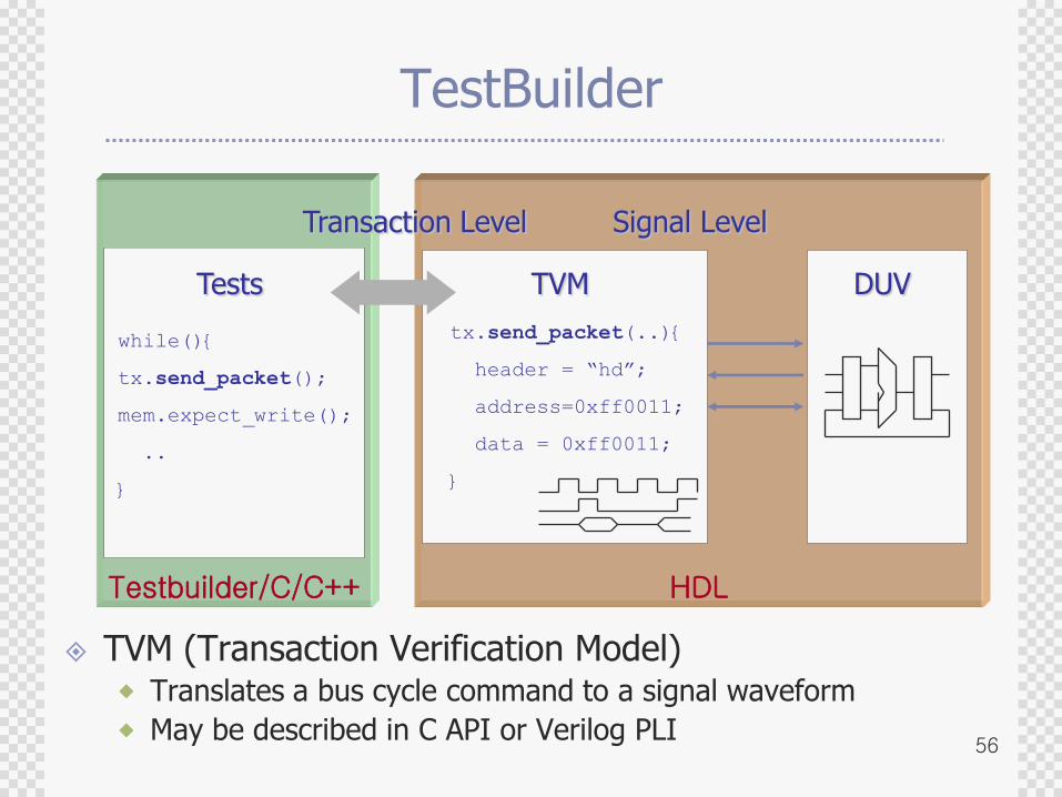
Testbuilder/C/C++ HDL
TestBuilder
Signal LevelTransaction Level
Tests TVM DUV
while(){
tx.send_packet();
mem.expect_write();
..
}
tx.send_packet(..){
header = “hd”;
address=0xff0011;
data = 0xff0011;
}
TVM (Transaction Verification Model) Translates a bus cycle command to a signal waveform
May be described in C API or Verilog PLI
57
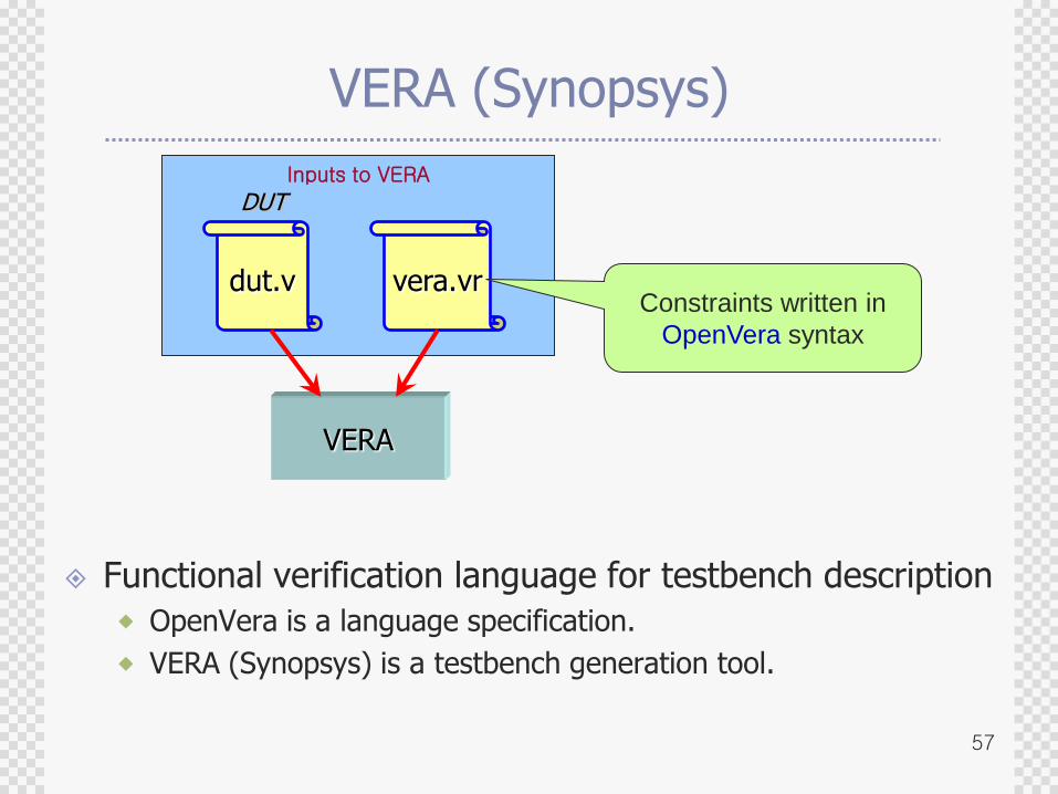
Inputs to VERA
VERA (Synopsys)
dut.v vera.vr
VERA
DUT
Functional verification language for testbench description
OpenVera is a language specification.
VERA (Synopsys) is a testbench generation tool.
Constraints written in
OpenVera syntax
58
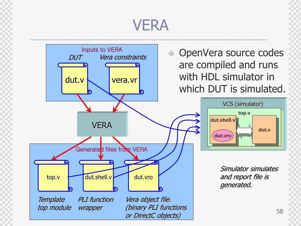
Generated files from VERA
Inputs to VERA
VERA
dut.v vera.vr
VERA
top.v dut.shell.v dut.vro
DUT Vera constraints
Template top module
PLI function wrapper
Vera object file. (binary PLI functions or DirectC objects)
OpenVera source codes are compiled and runs with HDL simulator in which DUT is simulated.
Simulator simulates and report file is generated.
VCS (simulator)
top.v
dut.shell.v
dut.vro
dut.v
59
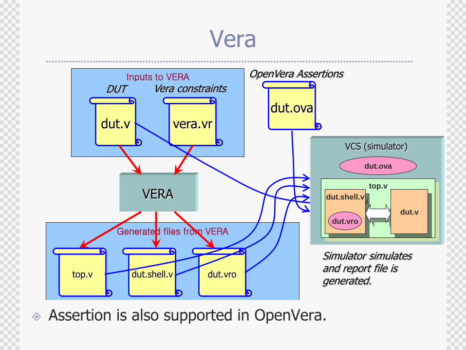
Generated files from VERA
Inputs to VERA
Vera
dut.v vera.vr
VERA
top.v dut.shell.v dut.vro
DUT Vera constraints
Template top module
PLI function wrapper
Vera object file. (binary PLI functions or DirectC objects)
dut.ova
OpenVera Assertions
Assertion is also supported in OpenVera.
Simulator simulates and report file is generated.
VCS (simulator)
top.v
dut.shell.v
dut.vro
dut.v
dut.ova
60
SystemVerilog
SystemVerilog 3.1 provides design constructs for architectural, algorithmic and transaction-based modeling.
Adds an environment for automated testbench generation, while providing assertions to describe design functionality, including complex protocols, to drive verification using simulation or formal verification techniques.
Its C-API provides the ability to mix Verilog and C/C++ constructs without the need for PLI for direct data exchange.
61
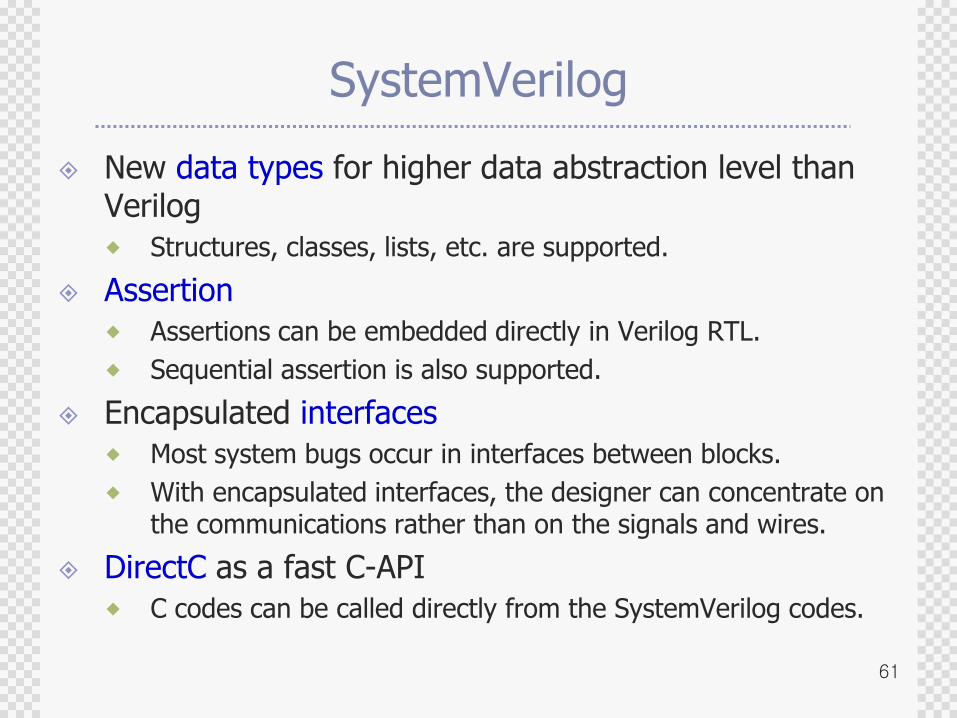
SystemVerilog
New data types for higher data abstraction level than Verilog
Structures, classes, lists, etc. are supported.
Assertion
Assertions can be embedded directly in Verilog RTL.
Sequential assertion is also supported.
Encapsulated interfaces
Most system bugs occur in interfaces between blocks.
With encapsulated interfaces, the designer can concentrate on the communications rather than on the signals and wires.
DirectC as a fast C-API
C codes can be called directly from the SystemVerilog codes.
62
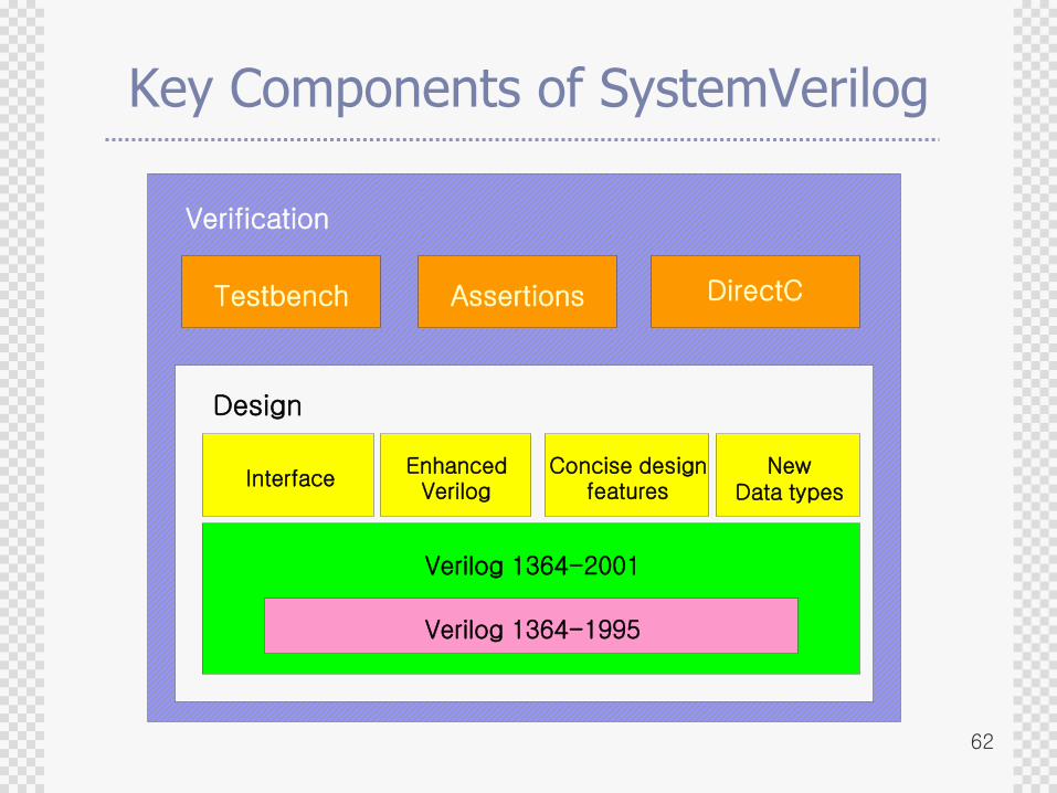
Key Components of SystemVerilog
Testbench Assertions DirectC
Entity
InterfaceEnhanced
VerilogConcise design
featuresNew
Data types
Verilog 1364-2001
Design
Verilog 1364-1995
Verification
63
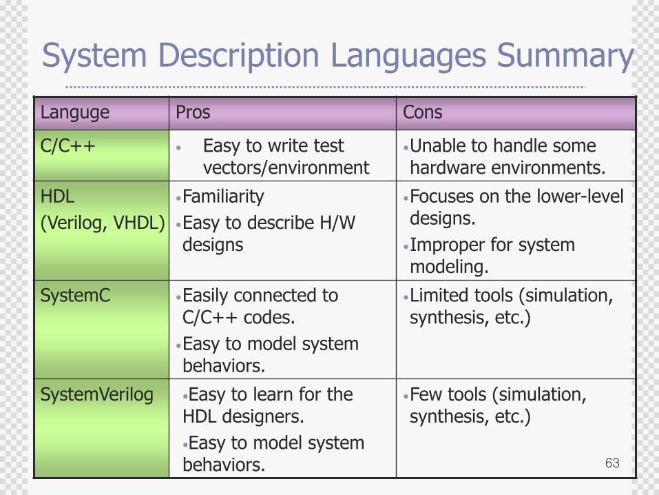
System Description Languages Summary
Languge Pros Cons
C/C++ • Easy to write test vectors/environment
•Unable to handle some hardware environments.
HDL
(Verilog, VHDL)
•Familiarity
•Easy to describe H/W designs
•Focuses on the lower-level designs.
•Improper for system modeling.
SystemC •Easily connected to C/C++ codes.
•Easy to model system behaviors.
•Limited tools (simulation, synthesis, etc.)
SystemVerilog •Easy to learn for the HDL designers.
•Easy to model system behaviors.
•Few tools (simulation, synthesis, etc.)
64
Agenda
Why Verification ?
Verification Alternatives
Languages for System Modeling and Verification
Verification with Progressive Refinement
Flexible SoC verification environment
Debugging features
Cycle vs. transaction mode verification
Emulation products
SoC Verification
Concluding Remarks
65
Criteria for Good SoC Verification Environment
Support various abstraction levels
Support heterogeneous design languages
Trade-off between verification speed and debugging features
Co-work with existing tools
Progressive refinement
Platform-based design
66
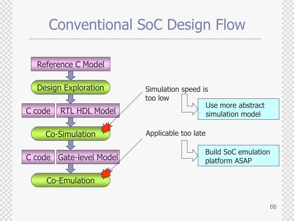
Conventional SoC Design Flow
Reference C Model
RTL HDL Model
Gate-level Model
Design Exploration
Co-Simulation
Co-Emulation
C code
C code
Simulation speed istoo low
Applicable too late
Use more abstractsimulation model
Build SoC emulationplatform ASAP
67
Core model
ISS
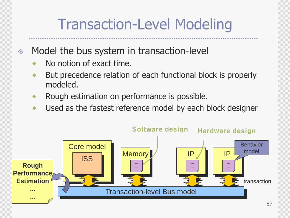
Transaction-Level Modeling
Model the bus system in transaction-level
No notion of exact time.
But precedence relation of each functional block is properly modeled.
Rough estimation on performance is possible.
Used as the fastest reference model by each block designer
Memory IP IP
Transaction-level Bus model
Rough
Performance
Estimation
...
...
Behavior
model
---
---
---
---
---
---
Software design Hardware design
transaction
68
Core model
ISS
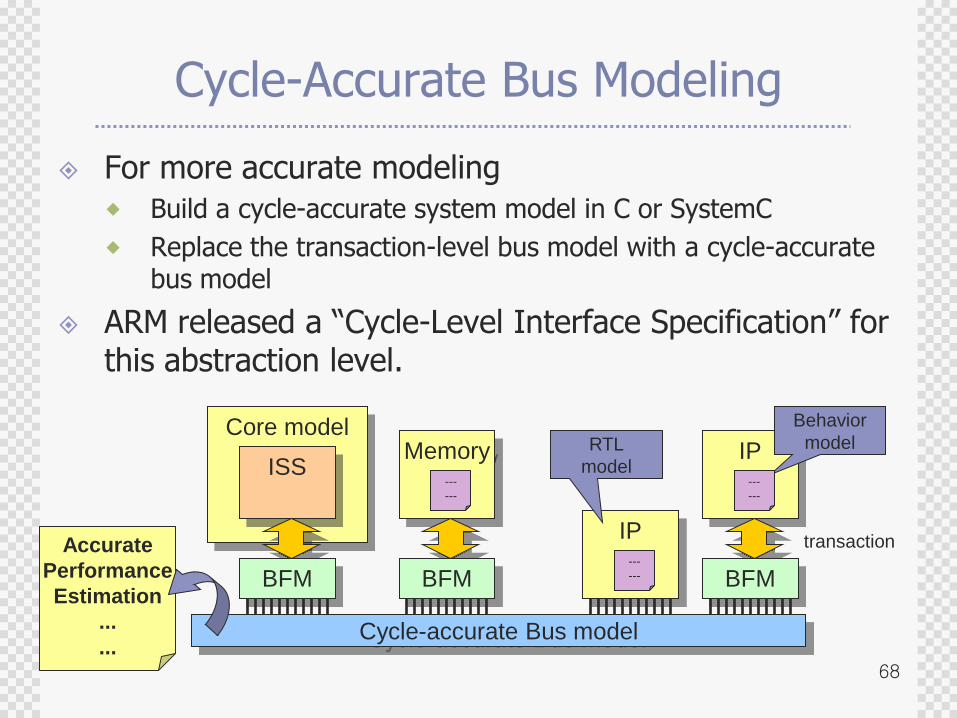
Cycle-Accurate Bus Modeling
For more accurate modeling
Build a cycle-accurate system model in C or SystemC
Replace the transaction-level bus model with a cycle-accurate bus model
ARM released a “Cycle-Level Interface Specification” for this abstraction level.
Memory
IP
IP
Cycle-accurate Bus model
Accurate
Performance
Estimation
...
...
Behavior
model
---
---
---
---
---
---
transaction
BFM BFM BFM
RTL
model
69
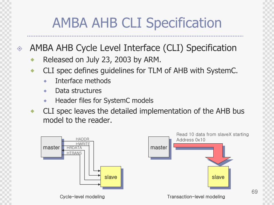
AMBA AHB CLI Specification
AMBA AHB Cycle Level Interface (CLI) Specification
Released on July 23, 2003 by ARM.
CLI spec defines guidelines for TLM of AHB with SystemC.
Interface methods
Data structures
Header files for SystemC models
CLI spec leaves the detailed implementation of the AHB bus model to the reader.
master
slave
master
HADDR
HWRITEHRDATA
HTRANS
slave
Read 10 data from slaveX startingAddress 0x10
Cycle-level modeling Transaction-level modeling
70
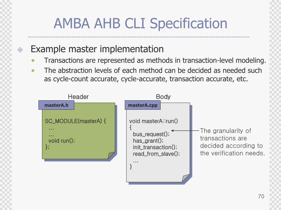
AMBA AHB CLI Specification
Example master implementation Transactions are represented as methods in transaction-level modeling.
The abstraction levels of each method can be decided as needed such as cycle-count accurate, cycle-accurate, transaction accurate, etc.
void masterA::run(){bus_request();has_grant();init_transaction();read_from_slave();...
}
Header Body
The granularity of transactions are decided according to the verification needs.
SC_MODULE(masterA) {......void run();
};
masterA.h masterA.cpp
71
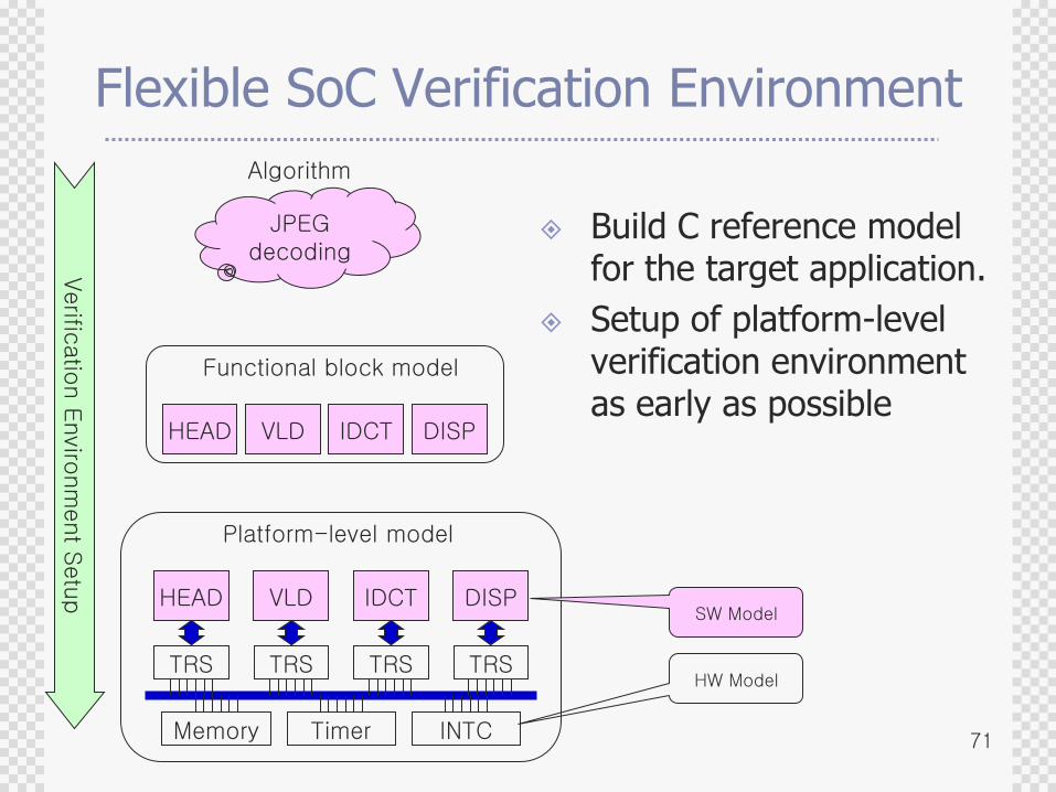
Flexible SoC Verification Environment
Build C reference model for the target application.
Setup of platform-level verification environment as early as possible
JPEG decoding
HEAD VLD IDCT DISP
Verific
atio
n E
nviro
nm
ent S
etu
p
Functional block model
TRS TRS TRS TRS
HEAD VLD IDCT DISP
Platform-level model
Algorithm
Memory Timer INTC
SW Model
HW Model
72
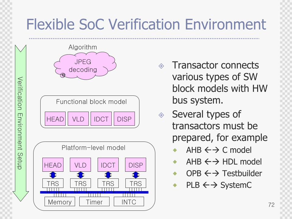
Flexible SoC Verification Environment
Transactor connects various types of SW block models with HW bus system.
Several types of transactors must be prepared, for example
AHB C model
AHB HDL model
OPB Testbuilder
PLB SystemC
JPEG decoding
HEAD VLD IDCT DISP
Verific
atio
n E
nviro
nm
ent S
etu
p
Functional block model
TRS TRS TRS TRS
HEAD VLD IDCT DISP
Platform-level model
Algorithm
Memory Timer INTC
73
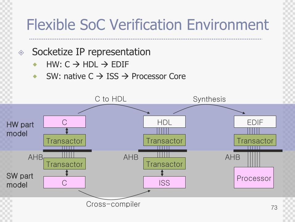
Flexible SoC Verification Environment
Socketize IP representation
HW: C HDL EDIF
SW: native C ISS Processor Core
C
Transactor
HDL
AHB
C to HDL
EDIF
Synthesis
Transactor
C
AHB
ISS
AHB
Processor
Cross-compiler
Transactor
Transactor
Transactor
SW partmodel
HW partmodel
74
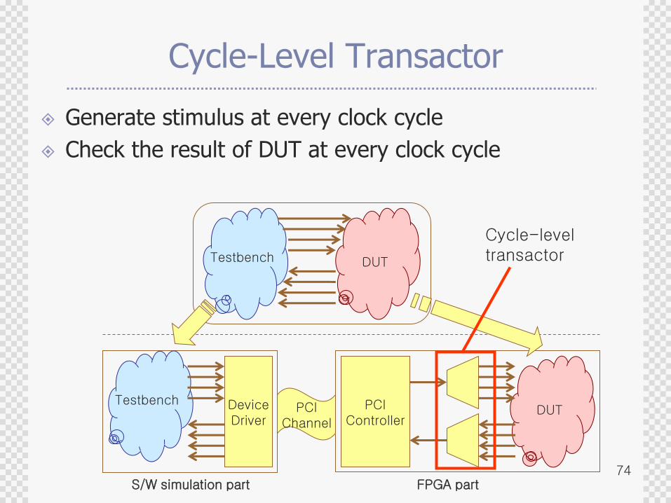
Cycle-Level Transactor
Generate stimulus at every clock cycle
Check the result of DUT at every clock cycle
PCIController
DUTPCIChannel
Testbench
Testbench DUT
FPGA part
DeviceDriver
S/W simulation part
Cycle-leveltransactor
75
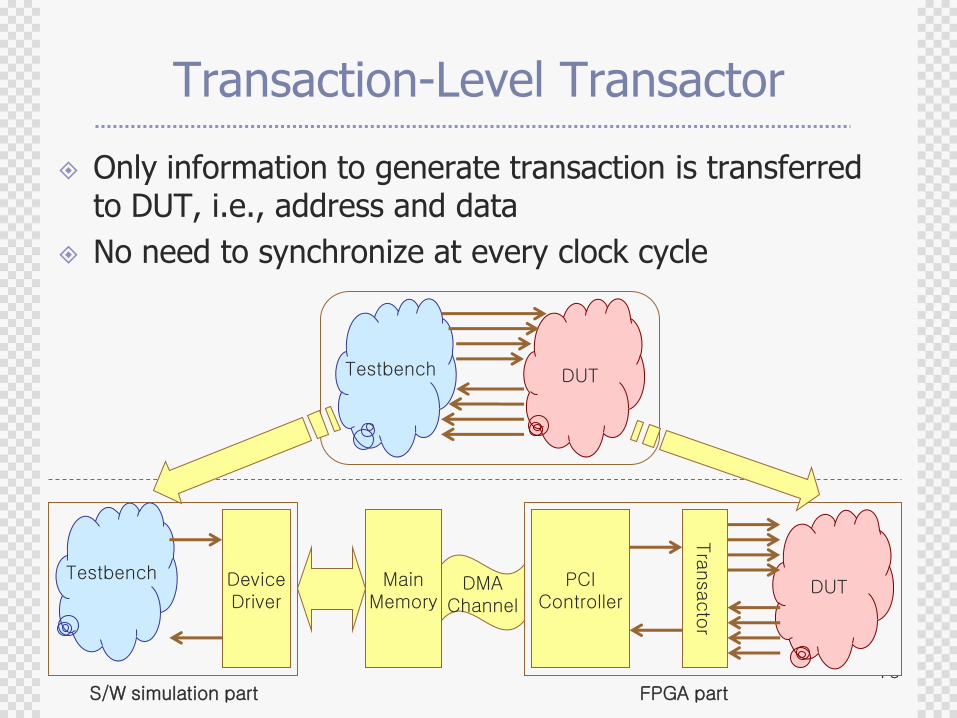
Transaction-Level Transactor
Only information to generate transaction is transferred to DUT, i.e., address and data
No need to synchronize at every clock cycle
PCIController
DUTDMAChannel
Testbench
Testbench DUT
FPGA part
DeviceDriver
S/W simulation part
Tra
nsacto
r
MainMemory
76
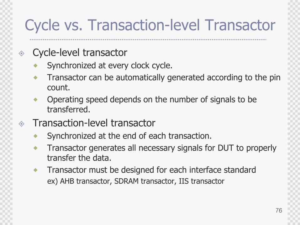
Cycle vs. Transaction-level Transactor
Cycle-level transactor
Synchronized at every clock cycle.
Transactor can be automatically generated according to the pin count.
Operating speed depends on the number of signals to be transferred.
Transaction-level transactor
Synchronized at the end of each transaction.
Transactor generates all necessary signals for DUT to properly transfer the data.
Transactor must be designed for each interface standard
ex) AHB transactor, SDRAM transactor, IIS transactor
77
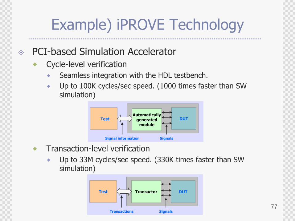
Example) iPROVE Technology
PCI-based Simulation Accelerator
Cycle-level verification
Seamless integration with the HDL testbench.
Up to 100K cycles/sec speed. (1000 times faster than SW simulation)
Transaction-level verification
Up to 33M cycles/sec speed. (330K times faster than SW simulation)
DUTTransactor
Transactions Signals
DUTTest
Signal information Signals
Automaticallygenerated
module
Test
78
OpenVera (OV) verification IP
Reusable verification modules, i.e.,
1) bus functional models,
2) traffic generators,
3) protocol monitors,
and
4) functional coverage blocks.
79
Companies providing OpenVera Verification IP
ControlNet IndiaIEEE 1394, TCP/IP Stack
GDA TechnologyHyperTransport
HCL TechnologiesI2C
IntegnologySmart Card Interface
nSysSIEEE 1284, UART
Qualis DesignEthernet 10/100, Ethernet 10/100/1G, Ethernet 10G, PCI-X, PCI, PCI Express Base, PCI Express AS, 802.11b, ARM AMBA AHB, USB 1.1, USB 2.0
Synopsys, Inc.AMBA AHB, AMBA APB, USB, Ethernet 10/100/1000, IEEE 1394, PCI/PCIx, SONET, SDH, ATM, IP, PDH
80
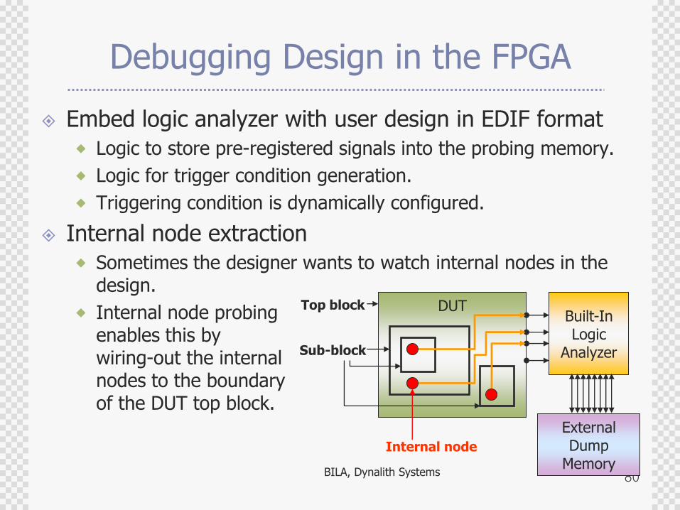
Debugging Design in the FPGA
Embed logic analyzer with user design in EDIF format
Logic to store pre-registered signals into the probing memory.
Logic for trigger condition generation.
Triggering condition is dynamically configured.
Internal node extraction
Sometimes the designer wants to watch internal nodes in the design.
Internal node probing enables this by wiring-out the internal nodes to the boundary of the DUT top block.
DUTBuilt-InLogic
Analyzer
Top block
Sub-block
Internal node
ExternalDump
MemoryBILA, Dynalith Systems
81
RTL Debugging Feature
Emulation is based on gate-level netlist.
Gate-level netlist generated from the synthesis tools has too complex name styles difficult to trace manually.
Techniques to resolve RTL symbol names from the gate-level symbol names and to provide debugging environment in RTL name spaces is required.
Insert RTL instrumentation IP for debugging Design flow
Read RTL design (Verilog, VHDL)
Generate instrumented RTL design (spiced with triggering and dump logic)
Synthesis
Compile (mapping & PAR)
DiaLite (Temento), Identify (Synplicity)
82
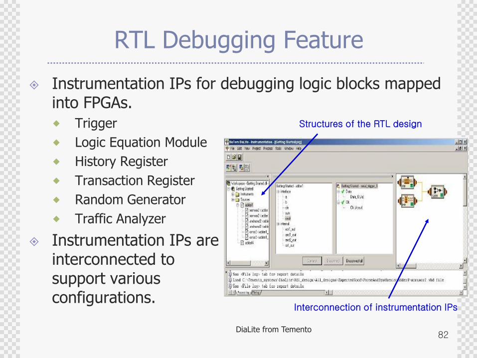
RTL Debugging Feature
Instrumentation IPs for debugging logic blocks mapped into FPGAs.
Trigger
Logic Equation Module
History Register
Transaction Register
Random Generator
Traffic Analyzer
Instrumentation IPs are interconnected to support various configurations.
Structures of the RTL design
Interconnection of instrumentation IPs
DiaLite from Temento
83
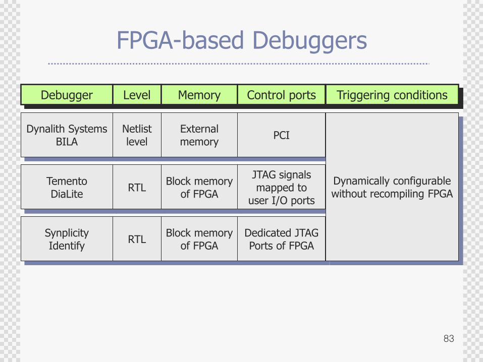
FPGA-based Debuggers
Debugger Level Memory Control ports Triggering conditions
Dynalith SystemsBILA
Netlistlevel
TementoDiaLite
RTLBlock memory
of FPGA
Externalmemory
PCI
JTAG signalsmapped to
user I/O ports
SynplicityIdentify
RTLBlock memory
of FPGADedicated JTAGPorts of FPGA
Dynamically configurablewithout recompiling FPGA
84
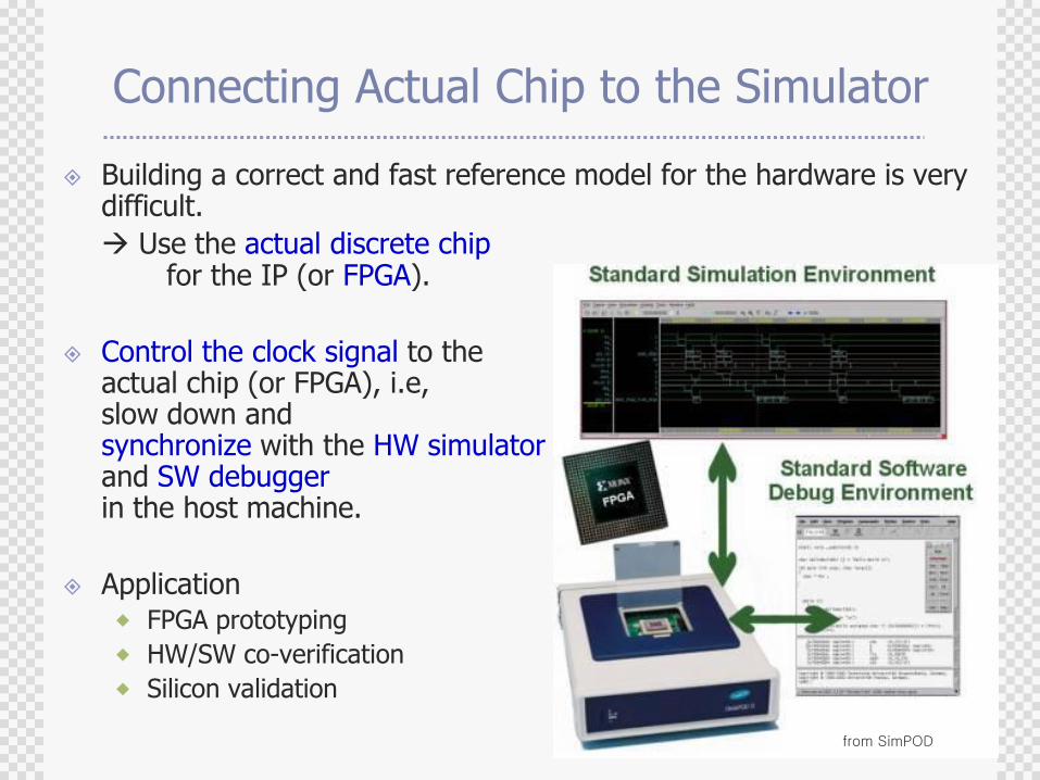
Connecting Actual Chip to the Simulator
Building a correct and fast reference model for the hardware is very difficult.
Use the actual discrete chipfor the IP (or FPGA).
Control the clock signal to the actual chip (or FPGA), i.e, slow down andsynchronize with the HW simulatorand SW debuggerin the host machine.
Application FPGA prototyping
HW/SW co-verification
Silicon validation
from SimPOD
85
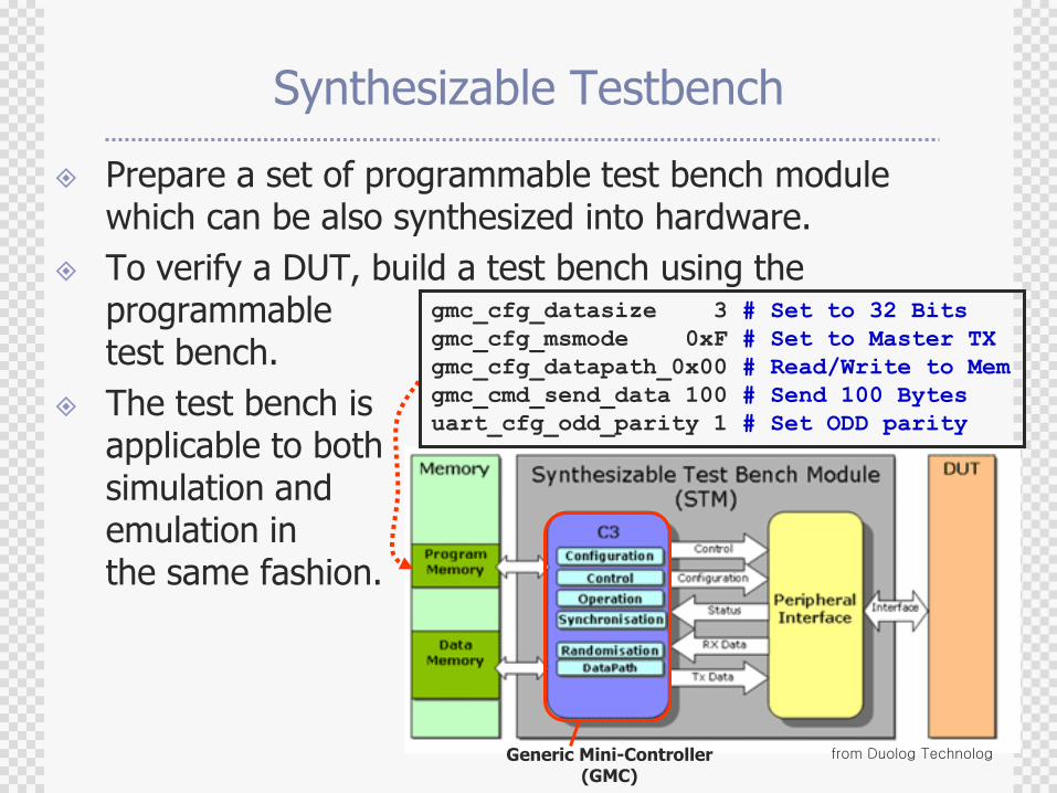
Synthesizable Testbench
Prepare a set of programmable test bench module which can be also synthesized into hardware.
To verify a DUT, build a test bench using the programmable test bench.
The test bench is applicable to both simulation and emulation in the same fashion.
from Duolog TechnologGeneric Mini-Controller(GMC)
gmc_cfg_datasize 3 # Set to 32 Bits
gmc_cfg_msmode 0xF # Set to Master TX
gmc_cfg_datapath_0x00 # Read/Write to Mem
gmc_cmd_send_data 100 # Send 100 Bytes
uart_cfg_odd_parity 1 # Set ODD parity
86
Large-Scale Emulators
Celaro, Mentor
Massive array of FPGA‟s
Distributed compilation
RTL debuggability
Full visibility without re-compilation
VStation, Mentor (IKOS)
Reduced routing problem by multiplexing multiple physical signal lines to a virtual wire.
Palladium, Quickturn (Cadence)
Use custom processor-array instead of FPGA
Support synthesizable testbench
Support multi-user operation
87
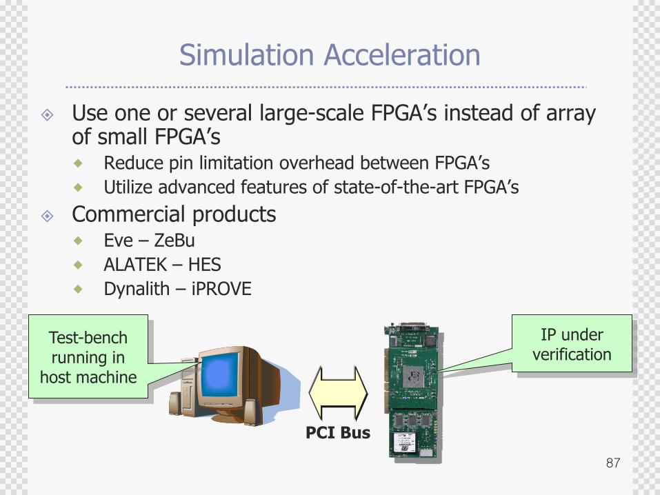
Simulation Acceleration
Use one or several large-scale FPGA‟s instead of array of small FPGA‟s Reduce pin limitation overhead between FPGA‟s
Utilize advanced features of state-of-the-art FPGA‟s
Commercial products Eve – ZeBu
ALATEK – HES
Dynalith – iPROVE
PCI Bus
IP underverification
Test-benchrunning in
host machine
88
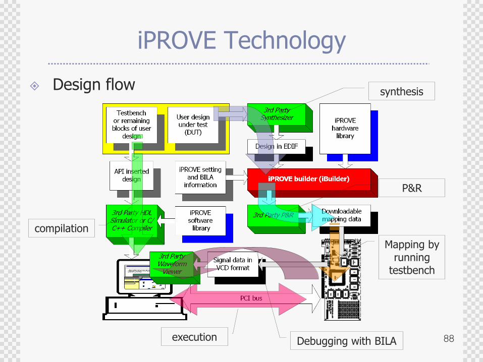
iPROVE Technology
Design flow
compilation
synthesis
P&R
Mapping by running
testbench
execution Debugging with BILA
89
Agenda
Why Verification ?
Verification Alternatives
Languages for System Modeling and Verification
Verification with Progressive Refinement
SoC Verification
Co-simulation
Co-emulation
Concluding Remarks
90
SoC Verification
Co-simulation
Connecting ISS with HDL simulation environment
Seamless, N2C
Co-emulation
Emulation/rapid-prototyping equipments supporting co-emulation
ARM Integrator, Aptix System Explorer, AXIS XoC, Dynalith iPROVE
91
What‟s the point in SoC Verification?
Mixture of SW and HW
Let the HW model to cooperate with Processor Model such as ISS or BFM (Bus functional model)
Mixture of pre-verified, unverified components
Utilize legacy IPs already verified
Mixture of different language, different abstraction levels
Provide common interface structure between SoC components
92
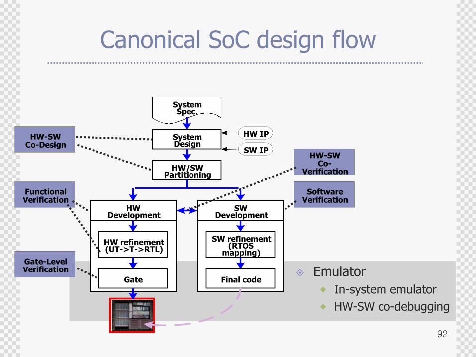
Canonical SoC design flow
SystemSpec.
SystemDesign
HW/SWPartitioning
HWDevelopment
SWDevelopment
HW refinement(UT->T->RTL)
Gate
HW IP
SW IP
SoftwareVerification
FunctionalVerification
Gate-LevelVerification
HW-SWCo-Design
HW-SWCo-
Verification
SW refinement(RTOS
mapping)
Final code Emulator
In-system emulator
HW-SW co-debugging
93
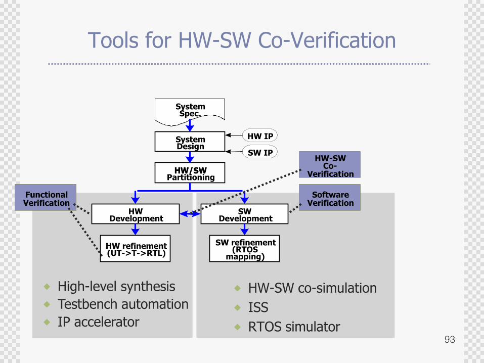
Tools for HW-SW Co-Verification
HW-SW co-simulation
ISS
RTOS simulator
HW/SWPartitioning
HWDevelopment
SWDevelopment
HW refinement(UT->T->RTL)
SoftwareVerification
FunctionalVerification
Co-Verification
SW refinement(RTOS
mapping)
HW-SW
High-level synthesis
Testbench automation
IP accelerator
SystemSpec.
SystemDesign
HW/SW
HW IP
SW IP
94
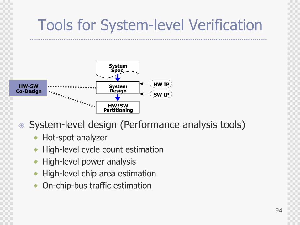
Tools for System-level Verification
System-level design (Performance analysis tools)
Hot-spot analyzer
High-level cycle count estimation
High-level power analysis
High-level chip area estimation
On-chip-bus traffic estimation
SystemSpec.
SystemDesign
HW/SWPartitioning
HW IP
SW IP
HW-SWCo-Design
95
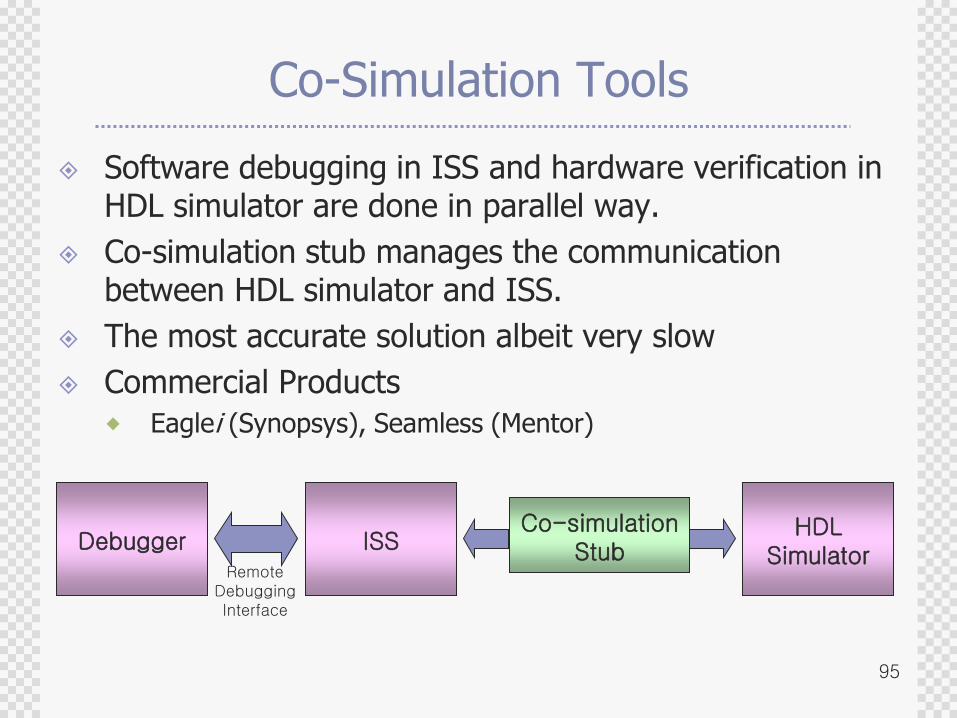
Co-Simulation Tools
Software debugging in ISS and hardware verification in HDL simulator are done in parallel way.
Co-simulation stub manages the communication between HDL simulator and ISS.
The most accurate solution albeit very slow
Commercial Products
Eaglei (Synopsys), Seamless (Mentor)
ISSHDL
Simulator
Co-simulationStubDebugger
RemoteDebuggingInterface
96
while(true) {
inst = fetch( pc );
opcode=decode(inst);
switch( opcode ){
…
case ADD:
…
break;
}
}
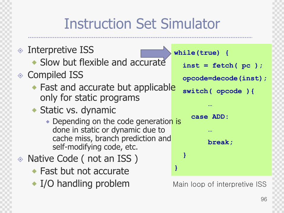
Instruction Set Simulator
Interpretive ISS
Slow but flexible and accurate
Compiled ISS
Fast and accurate but applicable only for static programs
Static vs. dynamic Depending on the code generation is
done in static or dynamic due tocache miss, branch prediction andself-modifying code, etc.
Native Code ( not an ISS )
Fast but not accurate
I/O handling problem Main loop of interpretive ISS
97
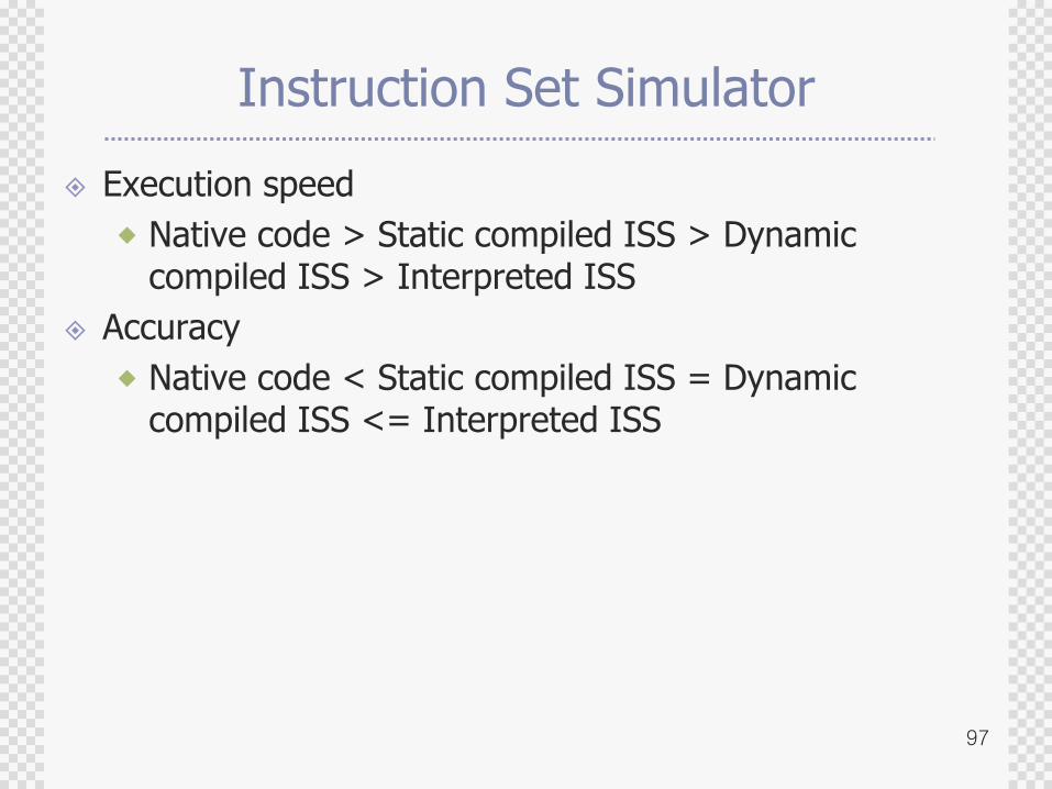
Instruction Set Simulator
Execution speed
Native code > Static compiled ISS > Dynamic compiled ISS > Interpreted ISS
Accuracy
Native code < Static compiled ISS = Dynamic compiled ISS <= Interpreted ISS
98
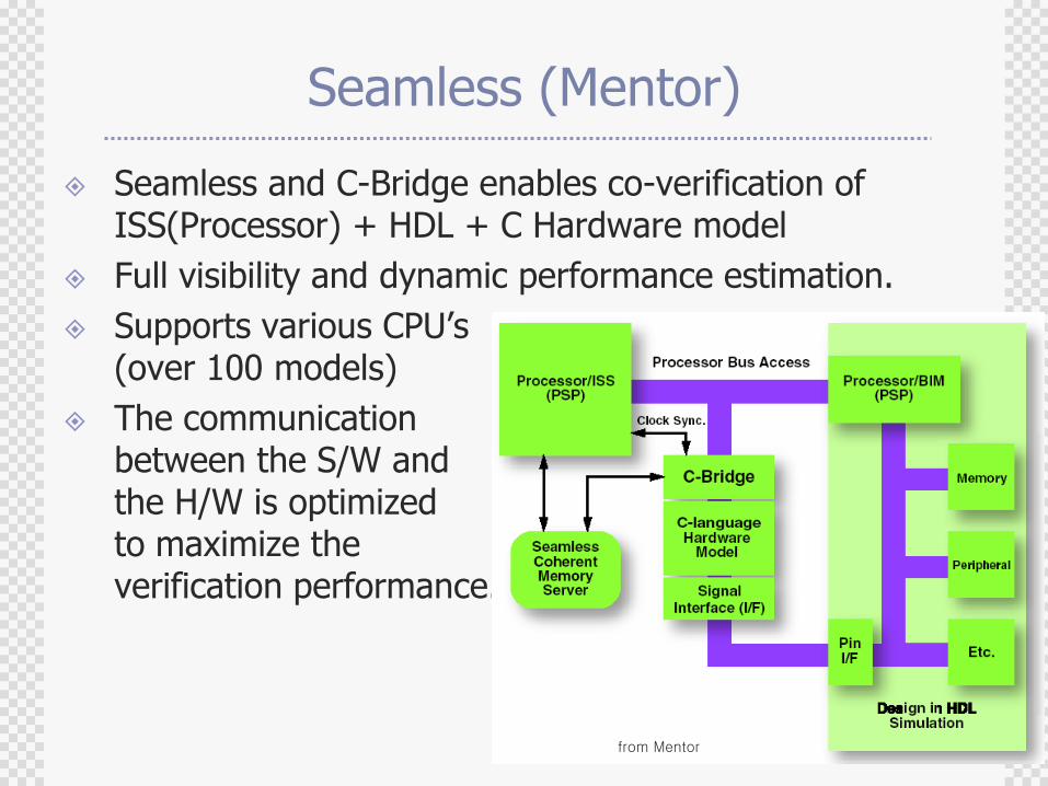
Seamless (Mentor)
Seamless and C-Bridge enables co-verification of ISS(Processor) + HDL + C Hardware model
Full visibility and dynamic performance estimation.
Supports various CPU‟s(over 100 models)
The communication between the S/W and the H/W is optimized to maximize the verification performance.
from Mentor
99
N2C
A set of tools allowing co-simulation of the system described in various abstraction levels
Un-timed C
Timed functional description
Behavioral bus cycle accurate description
RTC (Register Transfer C)
HDL with C
Interface synthesis to enable platform exploration
Interface synthesis make it possible to verify the performance of each platform efficiently in the early design stage.
Solving Hardware/software partitioning problems.
Deciding bus architecture of the SoC.
100
Co-Emulation Tools
Link hardware emulators with a processor model running in host machine or an actual processor core module
Most emulation and rapid prototyping products support linkage with ISS running in host machine
As the emulator runs very fast, speed of ISS including memory access as well as synchronization between emulation and ISS rise as new bottlenecks in verification
101
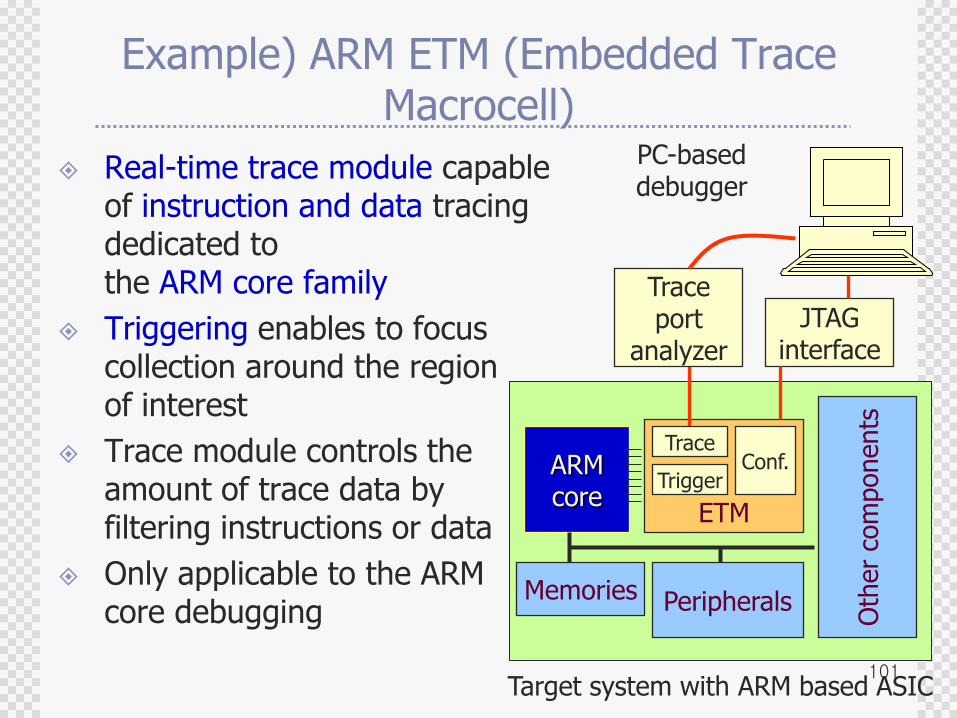
Example) ARM ETM (Embedded Trace Macrocell)
Real-time trace module capable of instruction and data tracing dedicated to the ARM core family
Triggering enables to focuscollection around the region of interest
Trace module controls theamount of trace data by filtering instructions or data
Only applicable to the ARMcore debugging
ARMcore
Memories Peripherals
Oth
er
com
ponents
ETM
Target system with ARM based ASIC
PC-based debugger
Trace
Trigger
Traceport
analyzer
JTAGinterface
Conf.
102
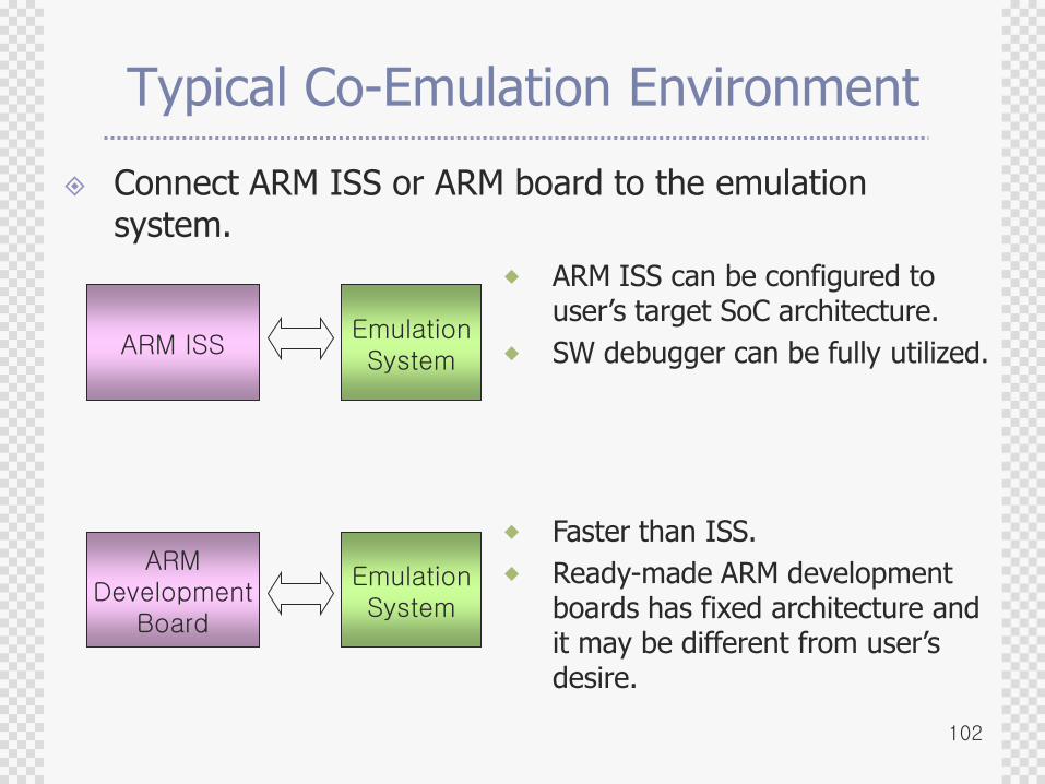
Typical Co-Emulation Environment
Connect ARM ISS or ARM board to the emulation system.
ARM ISSEmulationSystem
ARMDevelopment
Board
EmulationSystem
ARM ISS can be configured to user‟s target SoC architecture.
SW debugger can be fully utilized.
Faster than ISS.
Ready-made ARM development boards has fixed architecture and it may be different from user‟s desire.
103
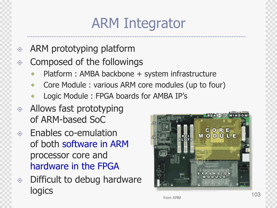
ARM Integrator
ARM prototyping platform
Composed of the followings
Platform : AMBA backbone + system infrastructure
Core Module : various ARM core modules (up to four)
Logic Module : FPGA boards for AMBA IP‟s
Allows fast prototypingof ARM-based SoC
Enables co-emulationof both software in ARMprocessor core andhardware in the FPGA
Difficult to debug hardwarelogics
from ARM
104
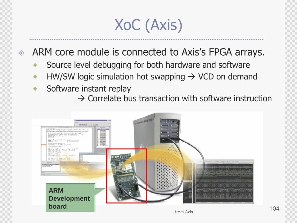
XoC (Axis)
ARM core module is connected to Axis‟s FPGA arrays.
Source level debugging for both hardware and software
HW/SW logic simulation hot swapping VCD on demand
Software instant replay Correlate bus transaction with software instruction
ARM
Development
boardfrom Axis
105
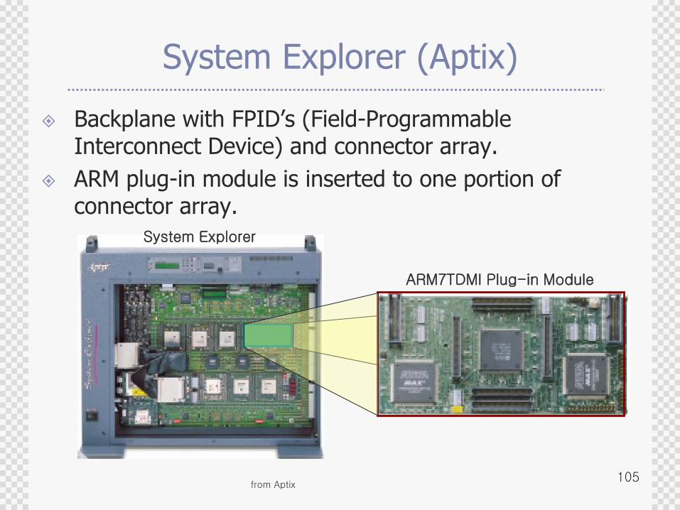
System Explorer (Aptix)
Backplane with FPID‟s (Field-Programmable Interconnect Device) and connector array.
ARM plug-in module is inserted to one portion of connector array.
System Explorer
ARM7TDMI Plug-in Module
from Aptix
106
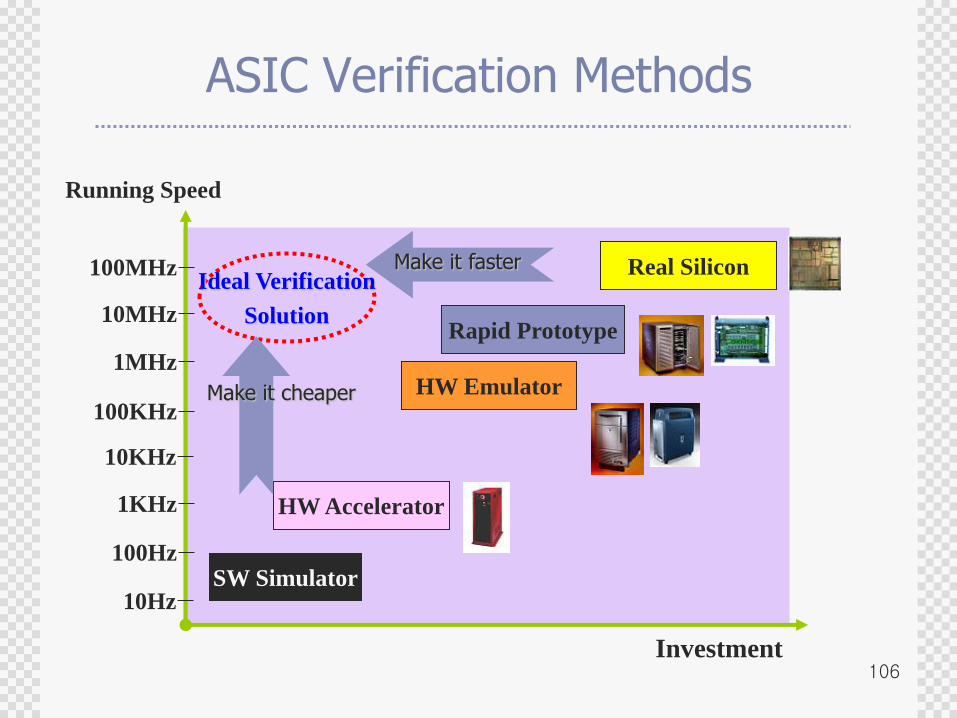
ASIC Verification Methods
Running Speed
10Hz
100Hz
1KHz
10KHz
100KHz
1MHz
10MHz
100MHz
SW Simulator
Investment
HW Emulator
Rapid Prototype
Real Silicon
HW Accelerator
Ideal Verification
Solution
Make it faster
Make it cheaper
107
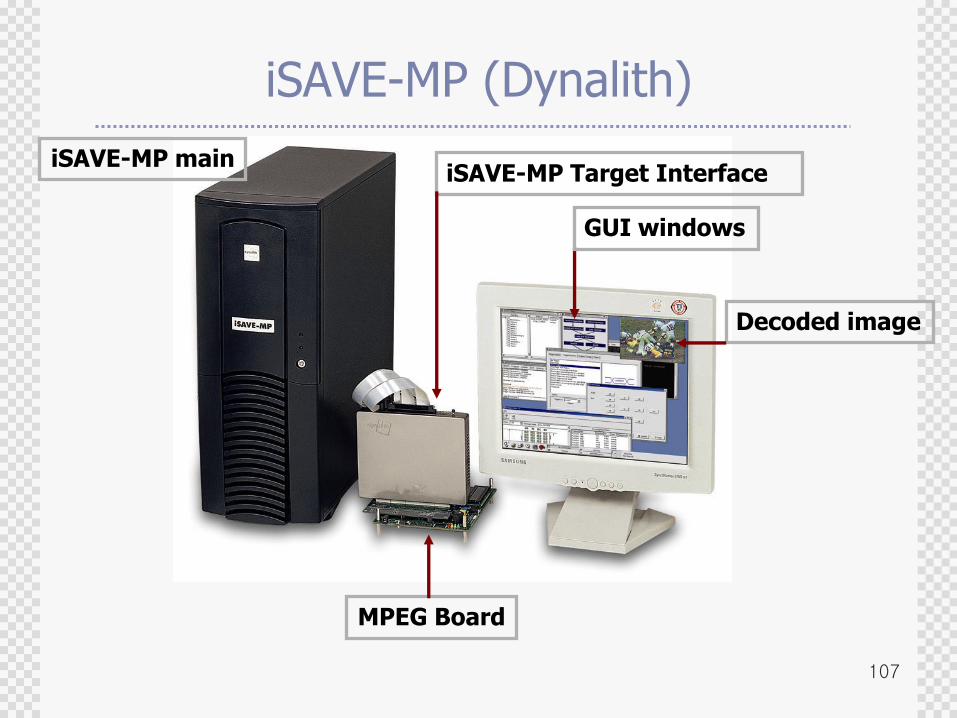
iSAVE-MP (Dynalith)
iSAVE-MP mainiSAVE-MP Target Interface
MPEG Board
Decoded image
GUI windows
108
FPGA
FPGA
C sessions
Designin EDIF
Designin EDIF
Transactor Transactor
Target board
I/F protocol I/F protocol
Inter-Lingual Communication
Designin C
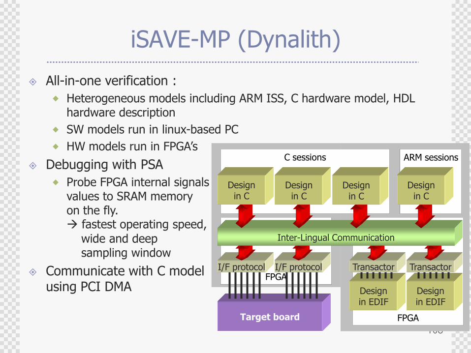
iSAVE-MP (Dynalith)
All-in-one verification :
Heterogeneous models including ARM ISS, C hardware model, HDL hardware description
SW models run in linux-based PC
HW models run in FPGA‟s
Debugging with PSA
Probe FPGA internal signalsvalues to SRAM memoryon the fly. fastest operating speed,
wide and deep sampling window
Communicate with C modelusing PCI DMA
ARM sessions
Designin C
Designin C
Designin C
109
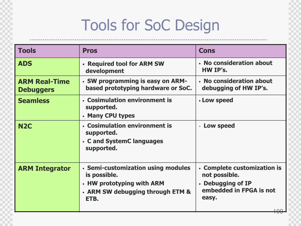
Tools for SoC Design
Tools Pros Cons
ADS • Required tool for ARM SW
development
• No consideration about HW IP’s.
ARM Real-Time Debuggers
• SW programming is easy on ARM-based prototyping hardware or SoC.
• No consideration about debugging of HW IP’s.
Seamless • Cosimulation environment is supported.
• Many CPU types
• Low speed
N2C • Cosimulation environment is supported.
• C and SystemC languages supported.
• Low speed
ARM Integrator • Semi-customization using modules is possible.
• HW prototyping with ARM
• ARM SW debugging through ETM & ETB.
• Complete customization is not possible.
• Debugging of IP embedded in FPGA is not easy.
110
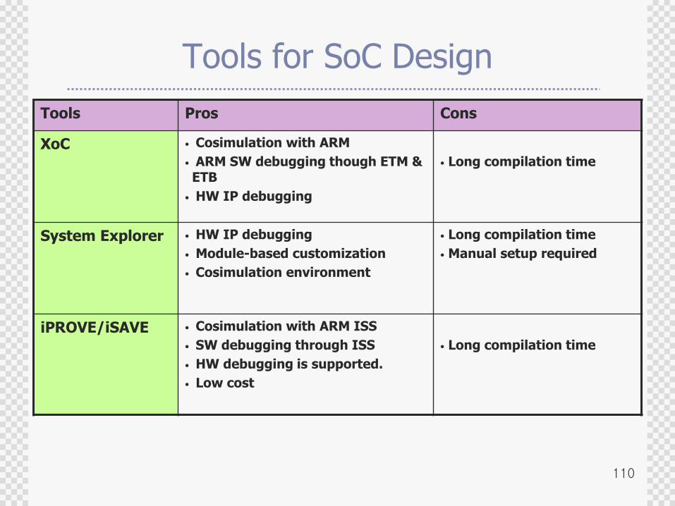
Tools for SoC Design
Tools Pros Cons
XoC • Cosimulation with ARM
• ARM SW debugging though ETM & ETB
• HW IP debugging
• Long compilation time
System Explorer • HW IP debugging
• Module-based customization
• Cosimulation environment
• Long compilation time
• Manual setup required
iPROVE/iSAVE • Cosimulation with ARM ISS
• SW debugging through ISS
• HW debugging is supported.
• Low cost
• Long compilation time
111
Agenda
Why Verification ?
Verification Alternatives
Languages for System Modeling and Verification
Verification with Progressive Refinement
SoC Verification
Concluding Remarks
112
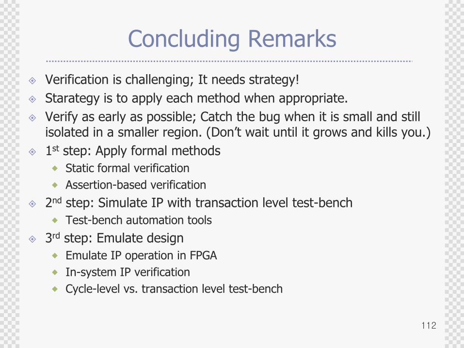
Concluding Remarks
Verification is challenging; It needs strategy!
Starategy is to apply each method when appropriate.
Verify as early as possible; Catch the bug when it is small and still isolated in a smaller region. (Don‟t wait until it grows and kills you.)
1st step: Apply formal methods
Static formal verification
Assertion-based verification
2nd step: Simulate IP with transaction level test-bench
Test-bench automation tools
3rd step: Emulate design
Emulate IP operation in FPGA
In-system IP verification
Cycle-level vs. transaction level test-bench
113
Concluding Remarks
Main differences of SoC with ASIC design are Planned IP-reuse
Reuse of pre-verified platform
Focus on co-verification with software
Newly added IP‟s must be thoroughly verified utilizing automated testbench and formal methods, if possible.
Well-established emulation platform helps, Progressive refinement of newly added SoC components
Early development and verification of software
Powerful debugging features handling both hardware part and software part are required.
Language, Tool/Data Interfaces need standardization.
DFV (Design for Verification) ; You lose in the beginning, but will win later, like Design for Reuse.

114
Thank You!!
115
iPROVE add-on‟s (cycle and trans mode example)
116
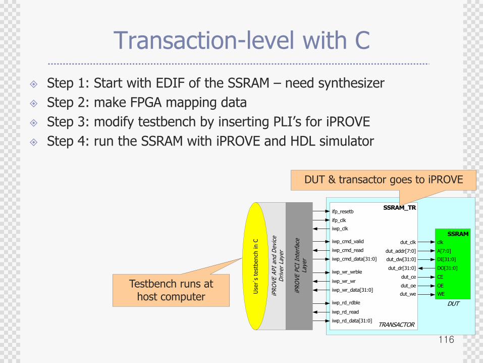
Transaction-level with C
Step 1: Start with EDIF of the SSRAM – need synthesizer
Step 2: make FPGA mapping data
Step 3: modify testbench by inserting PLI‟s for iPROVE
Step 4: run the SSRAM with iPROVE and HDL simulator
SSRAM
clk
A[7:0]
DI[31:0]
DO[31:0]
CE
OE
WE
SSRAM_TR
dut_clk
dut_addr[7:0]
dut_dw[31:0]
dut_dr[31:0]
dut_ce
dut_oe
dut_we
ifp_resetb
ifp_clk
iwp_clk
iwp_cmd_valid
iwp_cmd_read
iwp_cmd_data[31:0]
iwp_wr_wrble
iwp_wr_wr
iwp_wr_data[31:0]
iwp_rd_rdble
iwp_rd_read
iwp_rd_data[31:0]
Use
r’s
test
bench
in C
iPR
OV
E A
PI
and D
evi
ceD
rive
r La
yer
iPR
OV
E P
CI
Inte
rface
Laye
rDUT
TRANSACTOR
DUT & transactor goes to iPROVE
Testbench runs at host computer
117
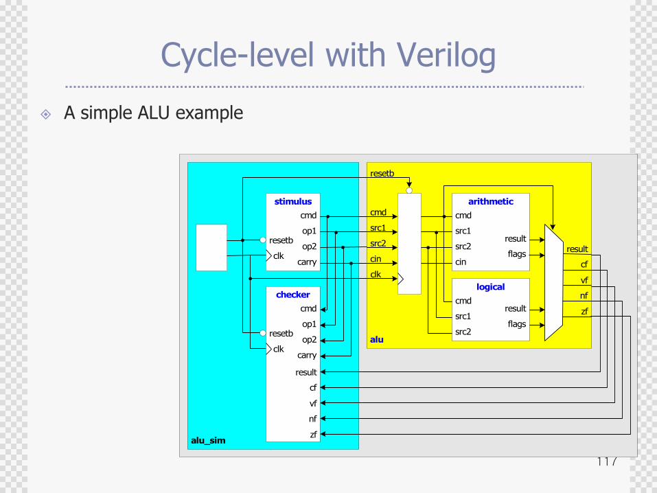
Cycle-level with Verilog
A simple ALU example
alu_sim
alu
arithmetic
cmd
src1
src2
cin
result
flags
logical
cmd
src1
src2
result
flags
cmd
src1
src2
cin
clk
resetb
result
cf
vf
nf
zf
stimulus
cmd
op1
op2
carryclk
resetb
checker
cmd
op1
op2
carryclk
resetb
result
cf
vf
nf
zf
118
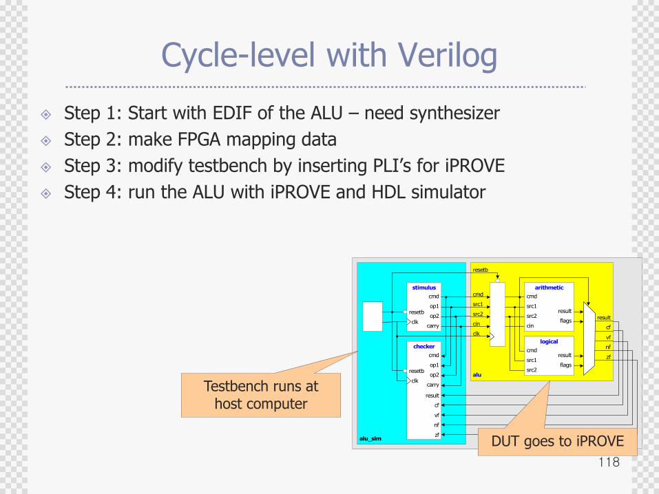
Cycle-level with Verilog
Step 1: Start with EDIF of the ALU – need synthesizer
Step 2: make FPGA mapping data
Step 3: modify testbench by inserting PLI‟s for iPROVE
Step 4: run the ALU with iPROVE and HDL simulator
alu_sim
alu
arithmetic
cmd
src1
src2
cin
result
flags
logical
cmd
src1
src2
result
flags
cmd
src1
src2
cin
clk
resetb
result
cf
vf
nf
zf
stimulus
cmd
op1
op2
carryclk
resetb
checker
cmd
op1
op2
carryclk
resetb
result
cf
vf
nf
zf
DUT goes to iPROVE
Testbench runs at host computer
119
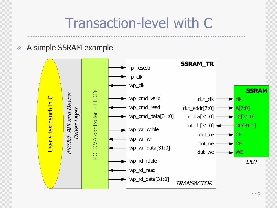
Transaction-level with C
A simple SSRAM example
SSRAM
clk
A[7:0]
DI[31:0]
DO[31:0]
CE
OE
WE
SSRAM_TR
dut_clk
dut_addr[7:0]
dut_dw[31:0]
dut_dr[31:0]
dut_ce
dut_oe
dut_we
ifp_resetb
ifp_clk
iwp_clk
iwp_cmd_valid
iwp_cmd_read
iwp_cmd_data[31:0]
iwp_wr_wrble
iwp_wr_wr
iwp_wr_data[31:0]
iwp_rd_rdble
iwp_rd_read
iwp_rd_data[31:0]
Use
r’s
test
bench
in C
iPR
OV
E A
PI
and D
evi
ceD
rive
r La
yer
iPR
OV
E P
CI
Inte
rface
Laye
r
DUT
TRANSACTOR
PC
I D
MA c
ontrolle
r + F
IFO
’s
120
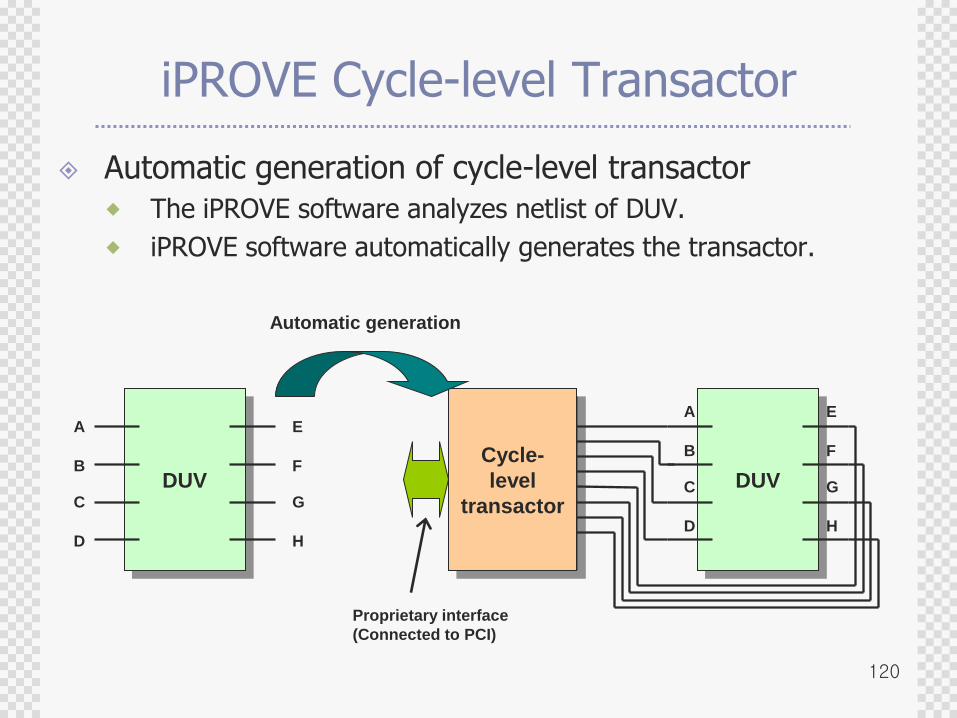
iPROVE Cycle-level Transactor
Automatic generation of cycle-level transactor
The iPROVE software analyzes netlist of DUV.
iPROVE software automatically generates the transactor.
DUV
A
B
C
D
E
F
G
H
DUV
Cycle-
level
transactor
A
B
C
D
E
F
G
H
Proprietary interface
(Connected to PCI)
Automatic generation
121
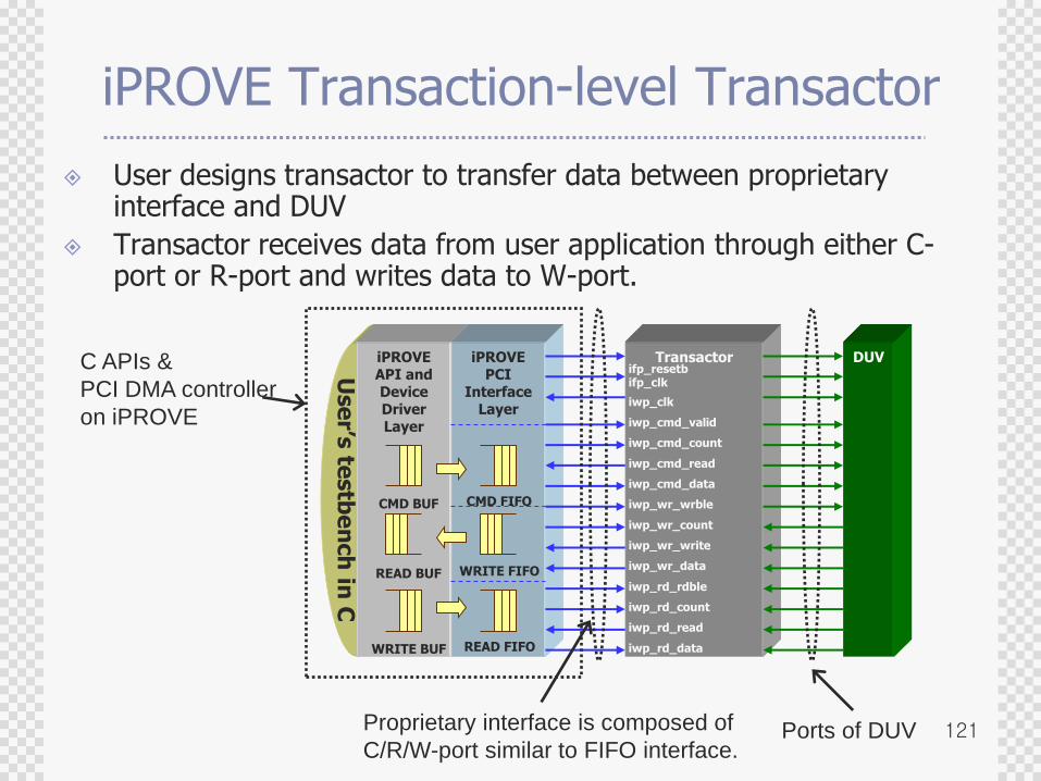
iPROVE Transaction-level Transactor
User designs transactor to transfer data between proprietary interface and DUV
Transactor receives data from user application through either C-port or R-port and writes data to W-port.
C APIs &
PCI DMA controller
on iPROVE
Use
r’s te
stb
en
ch
in C
iPROVEAPI andDeviceDriverLayer
iPROVEPCI
InterfaceLayer
Transactor DUV
CMD BUF
READ BUF
WRITE BUF
CMD FIFO
WRITE FIFO
READ FIFO
ifp_resetbifp_clk
iwp_clk
iwp_cmd_valid
iwp_cmd_count
iwp_cmd_read
iwp_cmd_data
iwp_wr_wrble
iwp_wr_count
iwp_wr_write
iwp_wr_data
iwp_rd_rdble
iwp_rd_count
iwp_rd_read
iwp_rd_data
Proprietary interface is composed of
C/R/W-port similar to FIFO interface.Ports of DUV