Embed Size (px)
Citation preview
30th ICPIG, August 28th - Septemper 2nd, 2011, Belfast, UK Topic number A4
Current-Voltage characteristics of nonharmonicallymodulated plasma boundary sheaths
Abd Elfattah T. Elgendy, D. Eremin , T. Mussenbrock , Ralf Peter Brinkmann
Institute for Theoretical Electrical Engineering, Ruhr University Bochum, Bochum, Germany
Abstract:
The dynamics of dual frequency capacitive RF discharges is largely dominated by the
charge-voltage characteristics of the plasma boundary sheath, which in turn is dependent
on the characteristcs of the modulation. This contribution focuses on the behavior of
the sheath under nonharmonic excitation, such as square, sawtooth, dual frequency and
pulse-like excitation. Fluid model of a collisional sheath and a PIC simulation of different
complexety and computational efficiency is established and compared.
1. Introduction:
Plasma technology is applied in many areas thatrequire high quality and precision demands. Itis especially important in areas such as manu-facturing of semiconductors, solar cells, textile,medical technologies,etc. Capacitively coupledplasmas (CCPs), are widely used for materialprocessing. In recent years it was realized thatfurther improvement of plasma processes cannotbe achieved without an improved insight in theirfunctioning. The sheath controls the energy andangular distribution of the ions, efficiency of theenergy coupling and characteristics of the non-linear behavior. Theoretical and experimentalperspectives be studied. [1–8].In this work the driving different RF excitationsfrequency will invesigate in details based on exactmodel and PIC simulation, in its collision form.The result of different characteristic behaviour ofsheath plasma such as density of ion and electrondistribution, electric field, sheath charge, currentdistribution and V (Q) − Q characteristics curvewill study.
2. collisional sheath model
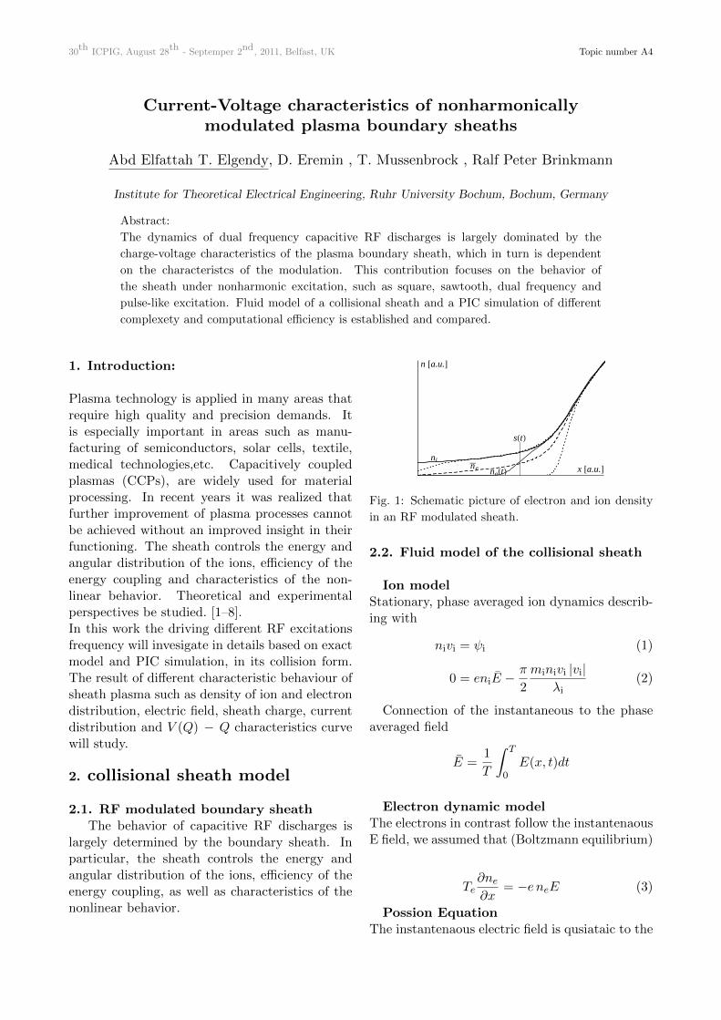
2.1. RF modulated boundary sheathThe behavior of capacitive RF discharges is
largely determined by the boundary sheath. Inparticular, the sheath controls the energy andangular distribution of the ions, efficiency of theenergy coupling, as well as characteristics of thenonlinear behavior.
ne
ni
neHtL
sHtL
x @a.u.D
n @a.u.D
Fig. 1: Schematic picture of electron and ion density
in an RF modulated sheath.
2.2. Fluid model of the collisional sheath
Ion modelStationary, phase averaged ion dynamics describ-ing with
nivi = ψi (1)
0 = eniE −π
2
minivi |vi|λi
(2)
Connection of the instantaneous to the phaseaveraged field
E =1
T
∫ T
0E(x, t)dt
Electron dynamic modelThe electrons in contrast follow the instantenaousE field, we assumed that (Boltzmann equilibrium)
Te∂ne∂x
= −e neE (3)
Possion EquationThe instantenaous electric field is qusiataic to the
30th ICPIG, August 28th - Septemper 2nd, 2011, Belfast, UK Topic number A4
charge density (which is parametrically RF mod-ulated)
ε0∂E
∂x= e (ni − ne) (4)
Equality of currentsEquality of ion and electron current
Ji = Je = e
√Te
2π me
1
T
∫ T
0nedt
∣∣∣x=0
(5)
Sheath charge
Charge of the sheath is coupled to RF excita-tion
Q(t) =
∫ ∞xE
e (ni − ne) dx (6)
= Q+J
ωRFF (ωRF t) (7)
A function F (ωRF t), refer to different type offunctions such as pulse excitation (Gaussian func-tion), square wave, Sawtooth wave and two fre-quency
F (ωRF t) = −0.5 + Q1√2πσ
e−(t−π)2
2σ2 (8)
= Q
k∑n=1
4
π
sin(2n− 1)t
2n− 1(9)
= Q
k∑n=1
2
π
sin(n)t
n(10)
= Q cos(ωt) +Q cos(3ωt) (11)
2.3. Particle-in-cell simulationThe code used in this work for independent
comparison is a 1d3v (one spatial dimension andthree dimensions in velocity space) self-consistentelectrostatic explicit kinetic code based onthe particle-in-cell algorithm enhanced withMonte-Carlo algorithm to treat collisions. In thisalgorithm, particle distribution function is dis-cretized by using markers (superparticles), whosenumber has to be large for good statistics, leadingto a large computational cost. To accelerate thesimulations, a coarse-sorting algorithm [9] wasused for massive parallelization of the code ongraphics processing unit. The resulting executiontime per particle is, for example, 0.8 ns in asimulation with 8 × 10⁶ particles. As a result, asimulation takes only a couple of hours to achieve
a stationary state. All simulations were startedwith 5 × 10⁶ particles, Te = 3 eV, Ti = 300 K,and p = 100 mTorr. The initial electron density,however, was taken to be a rough estimate of thedensity expected at the end of the simulation.For example, for the run with single frequencydriving voltage the initial electron density wastaken to be 4 × 10¹⁵ m−3, and for the doublefrequency run 3.2× 10¹⁶ m−3, respectively. [9]
Result of different F (ωRF t)
5 10 15 20 25 30 x
1
2
3
4
5
n
Π 2 Πt
FHΩtL=∆HtL
Π 2 Π t
50
125
200
V HtL
10 20 30 40 x
1
2
3
4
5
n
Π 2 Πt
-1
1
CosHtL+CosH5tL
Π 2 Π t
100
250
400
V HtL
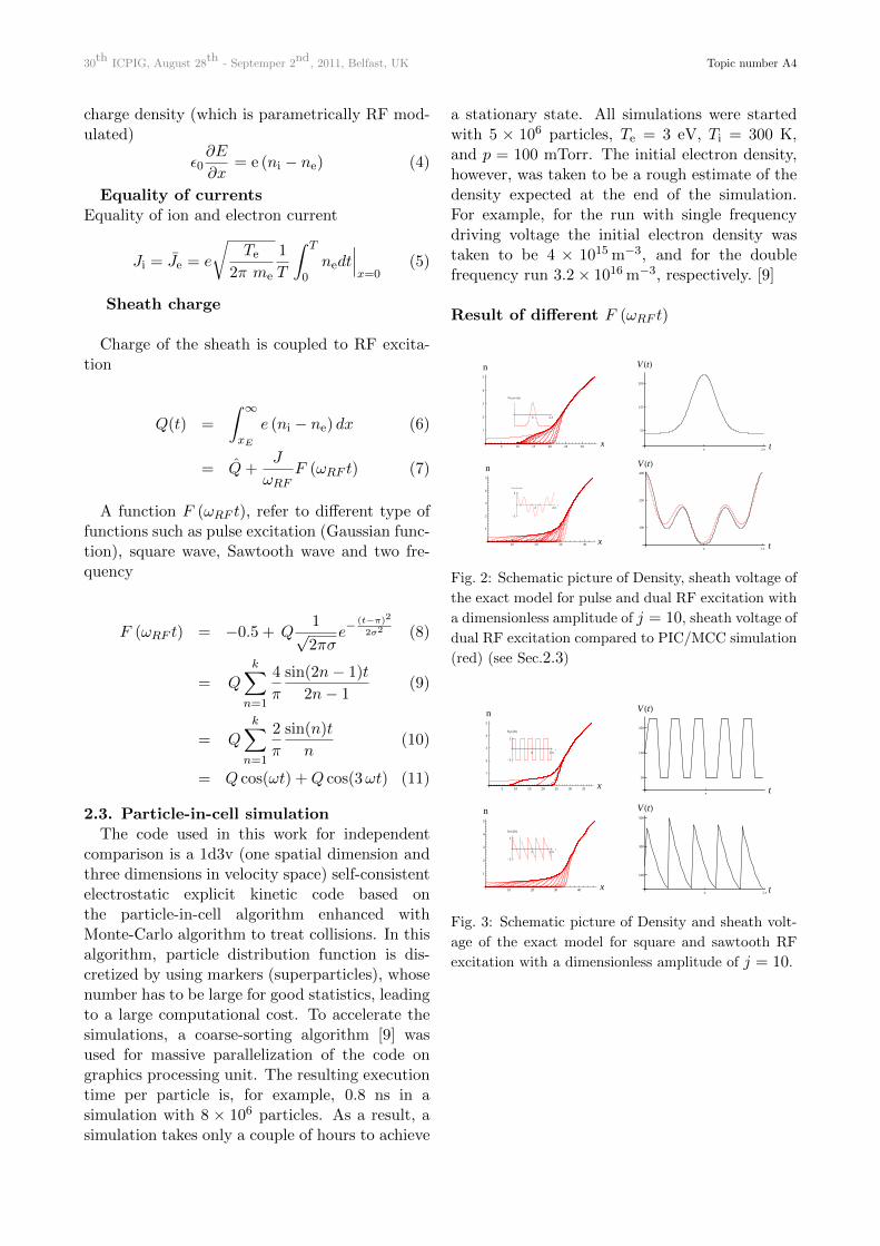
Fig. 2: Schematic picture of Density, sheath voltage of
the exact model for pulse and dual RF excitation with
a dimensionless amplitude of j = 10, sheath voltage of
dual RF excitation compared to PIC/MCC simulation
(red) (see Sec.2.3)
5 10 15 20 25 30 35 x
1
2
3
4
5
n
Π 2 Πt
-1
1
Sqw@5tD
Π t
50
150
250
V HtL
10 20 30 40 x
1
2
3
4
5
n
Π 2 Πt
-1
1
Saw@5tD
Π 2 Π t
100
300
500
V HtL
Fig. 3: Schematic picture of Density and sheath volt-
age of the exact model for square and sawtooth RF
excitation with a dimensionless amplitude of j = 10.
30th ICPIG, August 28th - Septemper 2nd, 2011, Belfast, UK Topic number A4
10 20 30 40x
-15
-10
-5
E
Π 2 Πt
-6
6
IHtL
10 20 30 40x
-15
-10
-5
E
Π 2 Πt
IHtL
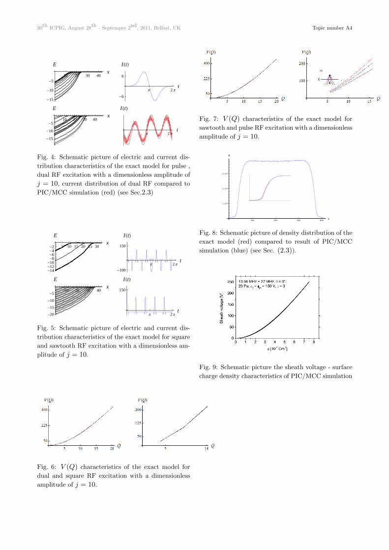
Fig. 4: Schematic picture of electric and current dis-
tribution characteristics of the exact model for pulse ,
dual RF excitation with a dimensionless amplitude of
j = 10, current distribution of dual RF compared to
PIC/MCC simulation (red) (see Sec.2.3)
5 10 15 20 25 30x
-14-12-10
-8-6-4-2
E
Π 2 Πt
-100
150
IHtL
10 20 30 40x
-20
-15
-10
-5
E
Π 2 Πt
150
IHtL
Fig. 5: Schematic picture of electric and current dis-
tribution characteristics of the exact model for square
and sawtooth RF excitation with a dimensionless am-
plitude of j = 10.
Fig. 6: V (Q) characteristics of the exact model for
dual and square RF excitation with a dimensionless
amplitude of j = 10.
Fig. 7: V (Q) characteristics of the exact model for
sawtooth and pulse RF excitation with a dimensionless
amplitude of j = 10.
1000 2000 3000 4000x
1 ´ 1016
2 ´ 1016
3 ´ 1016
n
Fig. 8: Schematic picture of density distribution of the
exact model (red) compared to result of PIC/MCC
simulation (blue) (see Sec. (2.3)).
Fig. 9: Schematic picture the sheath voltage - surface
charge density characteristics of PIC/MCC simulation
30th ICPIG, August 28th - Septemper 2nd, 2011, Belfast, UK Topic number A4
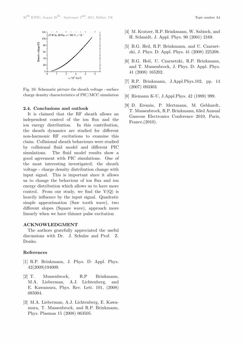
Fig. 10: Schematic picture the sheath voltage - surface
charge density characteristics of PIC/MCC simulation
2.4. Conclusions and outlookIt is claimed that the RF sheath allows an
independent control of the ion flux and theion energy distribution. In this contribution,the sheath dynamics are studied for differentnon-harmonic RF excitations to examine thisclaim. Collisional sheath behaviours were studiedby collisional fluid model and different PICsimulations. The fluid model results show agood agreement with PIC simulations. One ofthe most interesting investigated; the sheathvoltage - charge density distribution change withinput signal. This is important since it allowsus to change the behaviour of ion flux and ionenergy distribution which allows us to have morecontrol. From our study, we find the V(Q) isheavily influence by the input signal. Quadraticsimple approximation (Saw tooth wave), twodifferent slopes (Square wave), approach morelinearly when we have thinner pulse excitation
ACKNOWLEDGMENTThe authors gratefully appreciated the useful
discussions with Dr. J. Schulze and Prof. Z.Donko.
References
[1] R.P. Brinkmann, J. Phys. D: Appl. Phys.42(2009)194009.
[2] T. Mussenbrock, R.P Brinkmann,M.A. Lieberman, A.J. Lichtenberg, andE. Kawamura, Phys. Rev. Lett. 101, (2008)085004.
[3] M.A. Lieberman, A.J. Lichtenberg, E. Kawa-mura, T. Mussenbrock, and R.P. Brinkmann,Phys. Plasmas 15 (2008) 063505.
[4] M. Kratzer, R.P. Brinkmann, W. Sabisch, andH. Schmidt, J. Appl. Phys. 90 (2001) 2169.
[5] B.G. Heil, R.P. Brinkmann, and U. Czarnet-zki, J. Phys. D: Appl. Phys. 41 (2008) 225208.
[6] B.G. Heil, U. Czarnetzki, R.P. Brinkmann,and T. Mussenbrock, J. Phys. D: Appl. Phys.41 (2008) 165202.
[7] R.P. Brinkmann, J.Appl.Phys.102, pp. 14(2007) 093303.
[8] Riemann K-U, J.Appl.Phys. 42 (1989) 999.
[9] D. Eremin, P. Mertmann, M. Gebhardt,T. Mussenbrock, R.P. Brinkmann, 63rd AnnualGaseous Electronics Conference 2010, Paris,France,(2010).