Embed Size (px)
Citation preview
Course 3-4Fundamental notions of digital
telephony. The primary PCM multiplex.
Zsolt Polgar
Communications DepartmentFaculty of Electronics and
Telecommunications,Technical University of Cluj-Napoca
Cotent of the course Fundamental notions of digital telephony; PCM modulation; Delta modulation;
The primary PCM multiplex; The primary E1 multiplex; The primary T1 multiplex; Frame synchronization; Alarms; Line interfaces;
Data terminal – multiplexer interfaces;
Year 2012 – 2013Semester II
Telephony 2
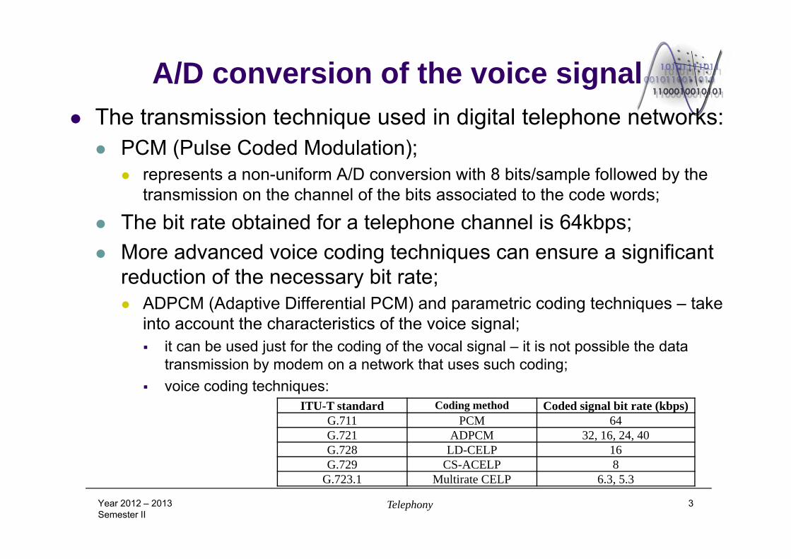
A/D conversion of the voice signal The transmission technique used in digital telephone networks: PCM (Pulse Coded Modulation);
represents a non-uniform A/D conversion with 8 bits/sample followed by the transmission on the channel of the bits associated to the code words;
The bit rate obtained for a telephone channel is 64kbps; More advanced voice coding techniques can ensure a significant
reduction of the necessary bit rate; ADPCM (Adaptive Differential PCM) and parametric coding techniques – take
into account the characteristics of the voice signal; it can be used just for the coding of the vocal signal – it is not possible the data
transmission by modem on a network that uses such coding; voice coding techniques:
Year 2012 – 2013Semester II
Telephony 3
ITU-T standard Coding method Coded signal bit rate (kbps)G.711 PCM 64G.721 ADPCM 32, 16, 24, 40G.728 LD-CELP 16G.729 CS-ACELP 8
G.723.1 Multirate CELP 6.3, 5.3
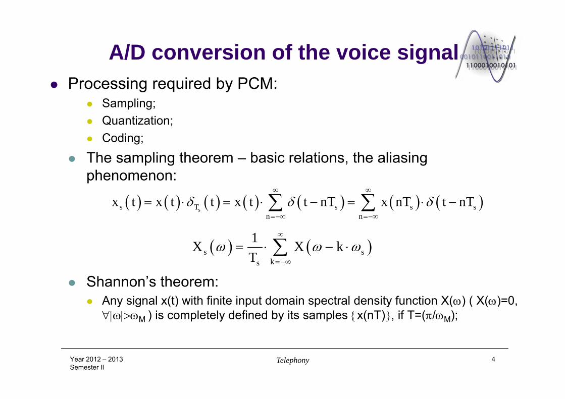
A/D conversion of the voice signal Processing required by PCM:
Sampling; Quantization; Coding;
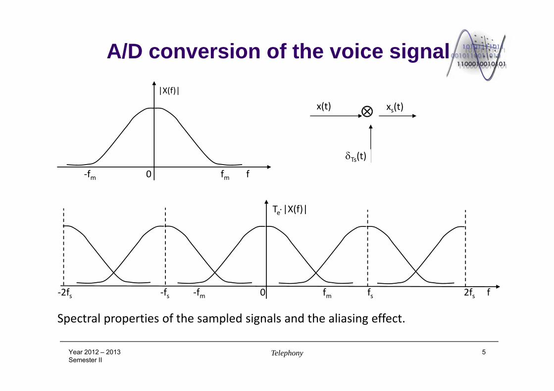
The sampling theorem – basic relations, the aliasing phenomenon:
Shannon’s theorem: Any signal x(t) with finite input domain spectral density function X() ( X()=0,
M ) is completely defined by its samples x(nT), if T=(/M);
Year 2012 – 2013Semester II
Telephony 4
ss T s s s
n nx t x t t x t t nT x nT t nT
s sks
1X X kT
A/D conversion of the voice signal
Year 2012 – 2013Semester II
Telephony 5
x(t) xs(t)
Ts(t)
‐fm 0 fm f
‐2fs ‐fs ‐fm 0 fm fs 2fs f
|X(f)|
Te|X(f)|
Spectral properties of the sampled signals and the aliasing effect.
A/D conversion of the voice signal
Year 2012 – 2013Semester II
Telephony 6
x(t) xs(t)
Ts(t)
‐fl 0 fl f
‐fs‐fl ‐fs ‐fs+fl ‐fl 0 fl fs‐fl fs fs+fl f
|Xf(f)|
Ts|Xf(f)|
LPFxf(t)
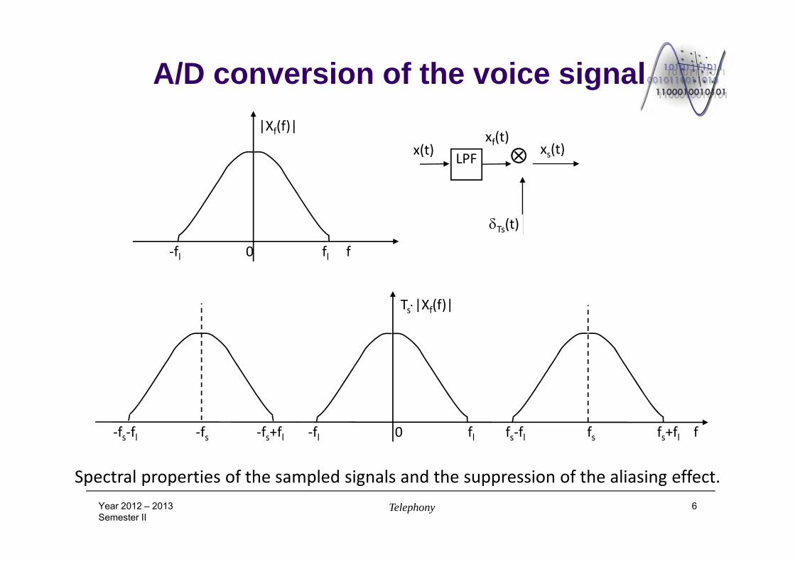
Spectral properties of the sampled signals and the suppression of the aliasing effect.
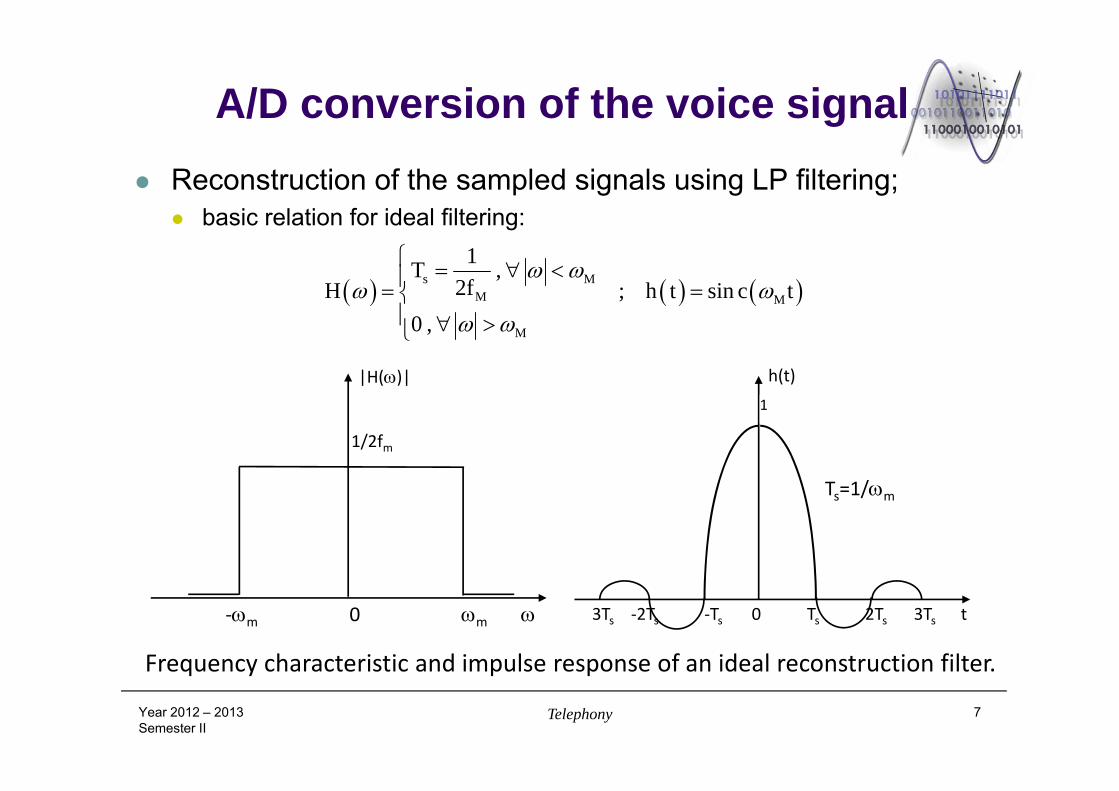
A/D conversion of the voice signal Reconstruction of the sampled signals using LP filtering;
basic relation for ideal filtering:
Year 2012 – 2013Semester II
Telephony 7
s MM M
M
1T ,2fH ; h t sin c t
0 ,
|H()|
‐m 0 m
h(t) 1
1/2fm
3Ts ‐2Ts ‐Ts 0 Ts 2Ts 3Ts t
Ts=1/m
Frequency characteristic and impulse response of an ideal reconstruction filter.
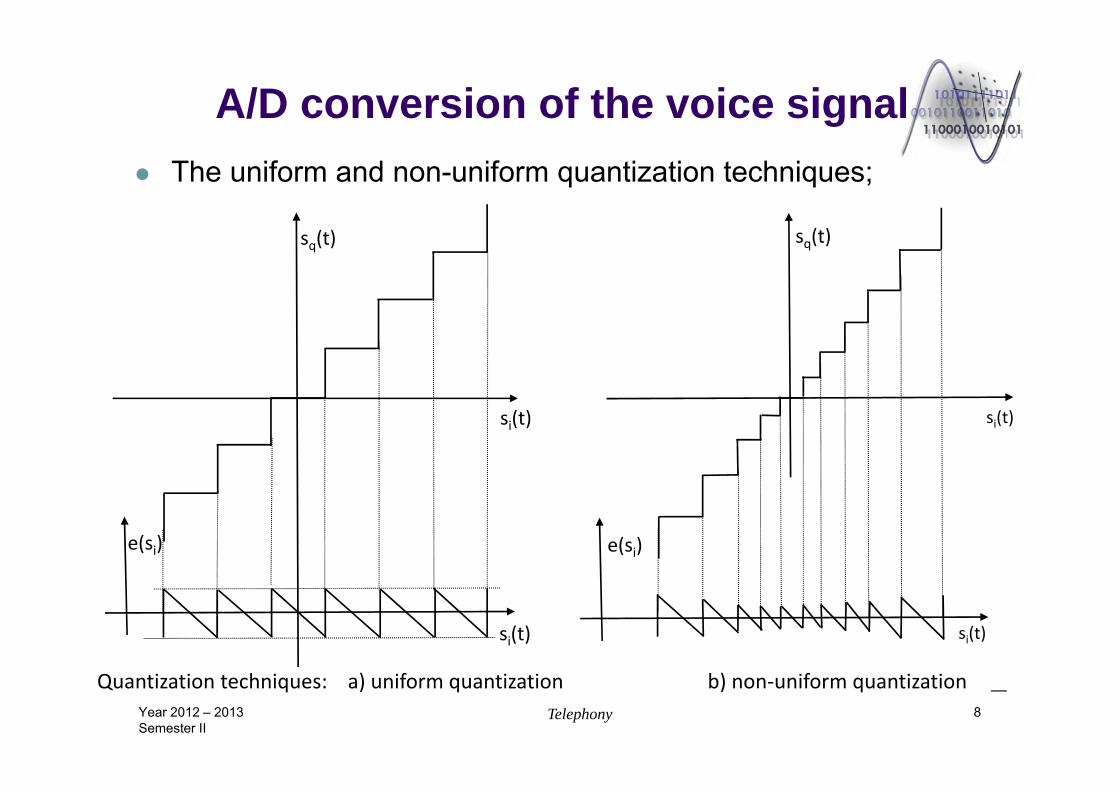
A/D conversion of the voice signal The uniform and non-uniform quantization techniques;
Year 2012 – 2013Semester II
Telephony 8
si(t)
e(si)
sq(t)
si(t)
sq(t)
si(t)
e(si)
Quantization techniques: a) uniform quantization b) non‐uniform quantization
si(t)
A/D conversion of the voice signal
Year 2012 – 2013Semester II
Telephony 9
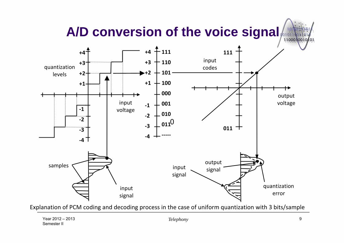
Explanation of PCM coding and decoding process in the case of uniform quantization with 3 bits/sample
111
110
101
100
000
001
010
011
‐‐‐‐‐
+4
+3
+2
+1
‐1
‐2
‐3
‐4
+4
+3
+2
+1
‐1
‐2
‐3
‐4
011
111
quantization levels
input voltage
input codes
samples
input signal
input signal
output signal
output voltage
quantization error
0
A/D conversion of the voice signal
Year 2012 – 2013Semester II
Telephony 10
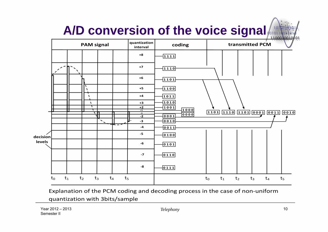
Explanation of the PCM coding and decoding process in the case of non‐uniform quantization with 3bits/sample
0 0 1 0
decisionlevels
1 1 1 1
1 1 1 0
1 1 0 1
1 1 0 0
1 0 1 1
1 0 1 0
1 0 0 11 0 0 00 0 0 0
0 1 1 1
0 0 1 0
0 1 0 1
0 1 0 0
0 0 1 1
0 0 0 1
0 1 1 0
1 1 0 1 1 1 1 0 1 1 0 1 0 0 0 1 0 0 1 1
+8
+7
+6
+5
+4
+3+2+1‐1
‐2‐3
‐4
‐5
‐6
‐7
‐8
t0 t1 t2 t3 t4 t5 t0 t1 t2 t3 t4 t5
quantizationintervalPAM signal coding transmitted PCM
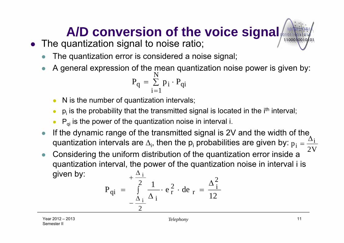
A/D conversion of the voice signal The quantization signal to noise ratio;
The quantization error is considered a noise signal; A general expression of the mean quantization noise power is given by:
N is the number of quantization intervals; pi is the probability that the transmitted signal is located in the ith interval; Pqi is the power of the quantization noise in interval i.
If the dynamic range of the transmitted signal is 2V and the width of the quantization intervals are i, then the pi probabilities are given by:
Considering the uniform distribution of the quantization error inside a quantization interval, the power of the quantization noise in interval i is given by:
Year 2012 – 2013Semester II
Telephony 11
N
1iqiiq PpP
V2p i
i
12dee1P
2i2
2
r2r
iqi
i
i
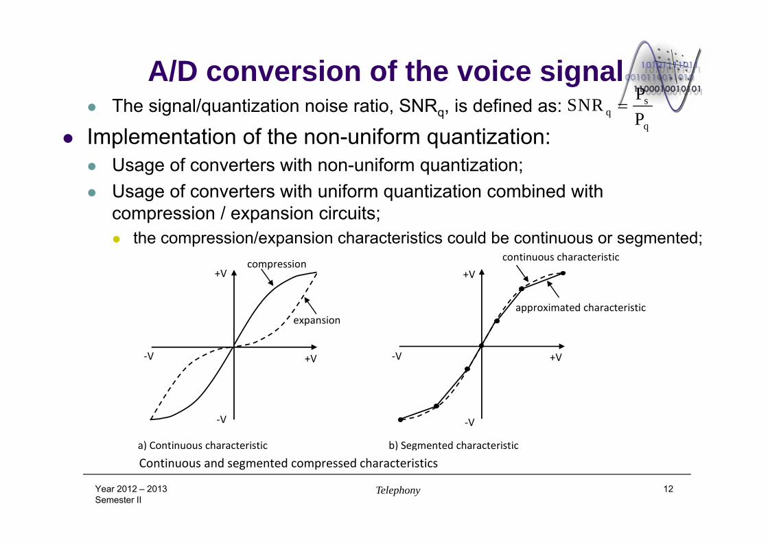
A/D conversion of the voice signal The signal/quantization noise ratio, SNRq, is defined as:
Implementation of the non-uniform quantization: Usage of converters with non-uniform quantization; Usage of converters with uniform quantization combined with
compression / expansion circuits; the compression/expansion characteristics could be continuous or segmented;
Year 2012 – 2013Semester II
Telephony 12
sq
q
PSNRP
Continuous and segmented compressed characteristics a) Continuous characteristic b) Segmented characteristic
+V
+V
‐V
‐V ‐V
‐V +V
+Vcompression
expansion
continuous characteristic
approximated characteristic
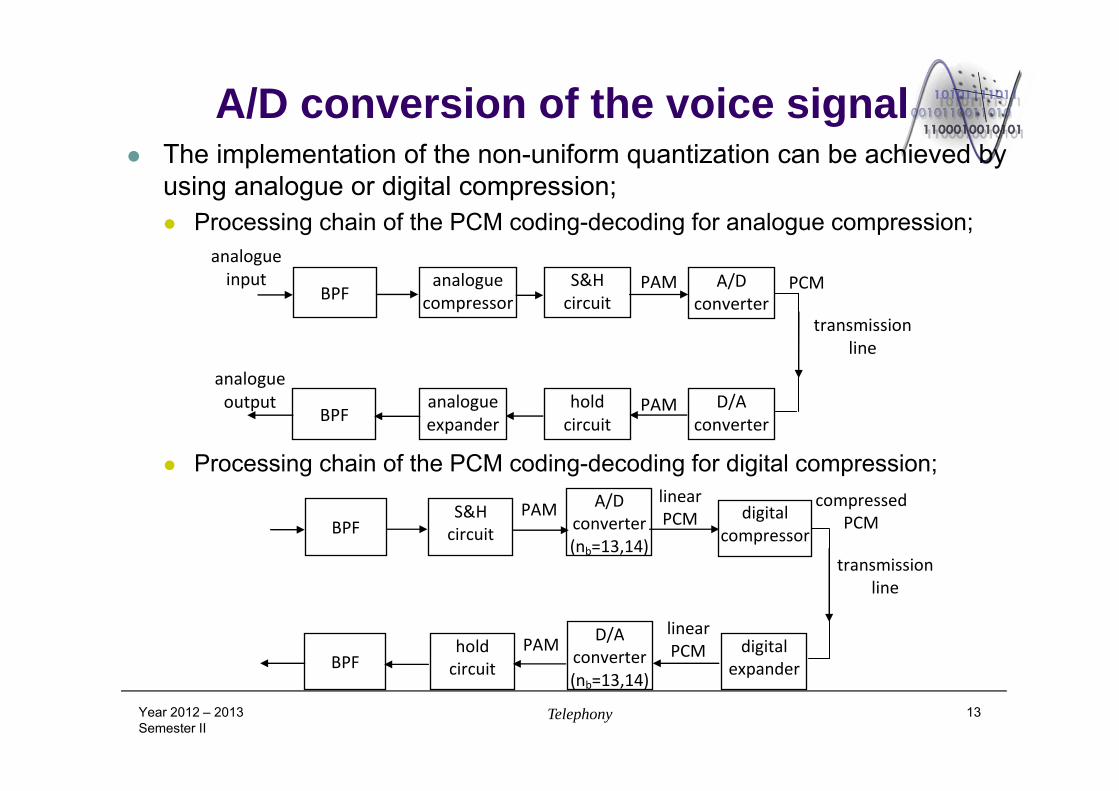
A/D conversion of the voice signal The implementation of the non-uniform quantization can be achieved by
using analogue or digital compression; Processing chain of the PCM coding-decoding for analogue compression;
Processing chain of the PCM coding-decoding for digital compression;
Year 2012 – 2013Semester II
Telephony 13
BPF S&Hcircuit
A/D converter (nb=13,14)
digitalcompressor
digitalexpander
D/A converter (nb=13,14)
holdcircuit BPF
PAM
PAM
compressedPCM
transmissionline
linearPCM
linearPCM
analogue input
BPF analogue
compressorS&Hcircuit
A/Dconverter
D/Aconverter
hold circuit
analogueexpanderBPF
PAM
PAM
PCM
analogue output
transmissionline
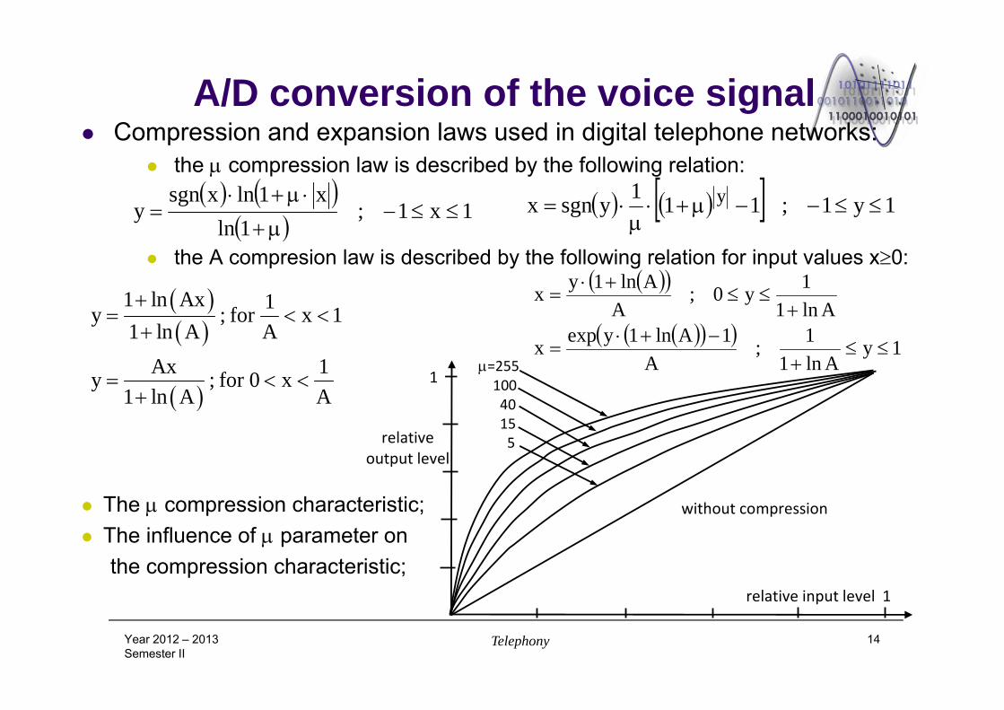
A/D conversion of the voice signal Compression and expansion laws used in digital telephone networks:
the compression law is described by the following relation:
the A compresion law is described by the following relation for input values x0:
The compression characteristic; The influence of parameter on
the compression characteristic;
Year 2012 – 2013Semester II
Telephony 14
1x1;1ln
x1lnxsgny
1y1;111ysgnx y
1 ln Ax 1y ; for x 11 ln A A
Ax 1y ; for 0 x1 ln A A
1yAln1
1;A
1Aln1yexpx
Aln11y0;
AAln1yx
relative output level
1
1
without compression
relative input level
=255 100 40 15 5
A/D conversion of the voice signal
Year 2012 – 2013Semester II
Telephony 15
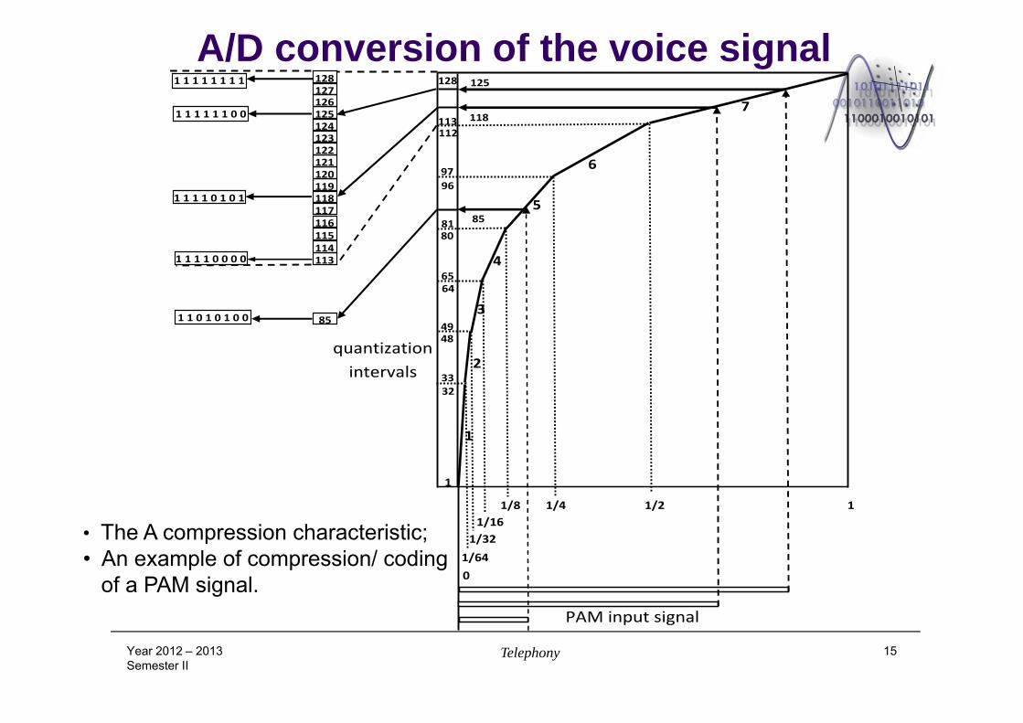
• The A compression characteristic;• An example of compression/ coding
of a PAM signal.
1/8 1/4 1/2 11/16
1/321/64 0
1
3233
4849
6465
8081
9697
112113
128
118
125
85
85
1131141151161171181191201211221231241251261271281 1 1 1 1 1 1 1
1 1 1 1 1 1 0 0
1 1 1 1 0 1 0 1
1 1 1 1 0 0 0 0
1 1 0 1 0 1 0 0
quantization intervals
1
2
3
4
5
6
7
PAM input signal
DPCM modulation Disadvantages of the PCM modulation:
Large transmission bandwidth – low spectral efficiency; The decrease of transmission bandwidth can be realized by exploiting
the correlation between the samples of the transmitted signal; the use of the correlation between the samples of the signal represents the
basic idea of the diferential PCM modulation;
DPCM modulation: The next sample is predicted based on the previous samples and it is
coded (quantized) only the difference between the current sample, x(kTe)=xk, and the predicted sample, x^k (kTs)=x^k ;
If the diffrence signal has a smaller dynamic range than that of the source signal the quantization can be performed on a smaller number of bits; the transmission rate can be reduced;
Year 2012 – 2013Semester II
Telephony 16
1
2 2 2 2 21 1 1 12 2 2
k k k
k k k k k k k k k k
d x x
d x x x x x x x x x
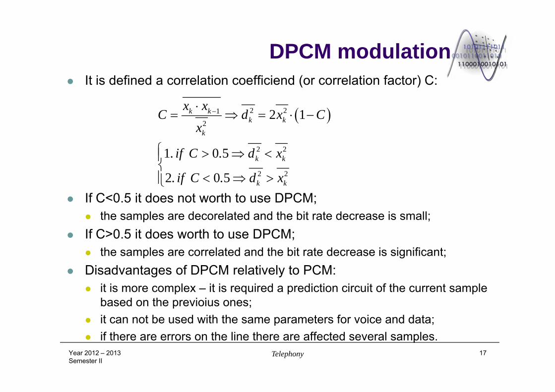
DPCM modulation It is defined a correlation coefficiend (or correlation factor) C:
If C<0.5 it does not worth to use DPCM; the samples are decorelated and the bit rate decrease is small;
If C>0.5 it does worth to use DPCM; the samples are correlated and the bit rate decrease is significant;
Disadvantages of DPCM relatively to PCM: it is more complex – it is required a prediction circuit of the current sample
based on the previoius ones; it can not be used with the same parameters for voice and data; if there are errors on the line there are affected several samples.
Year 2012 – 2013Semester II
Telephony 17
2 21
2
2 2
2 2
2 1
1 0 5
2 0 5
k kk k
k
k k
k k
x xC d x C
x
. if C . d x
. if C . d x
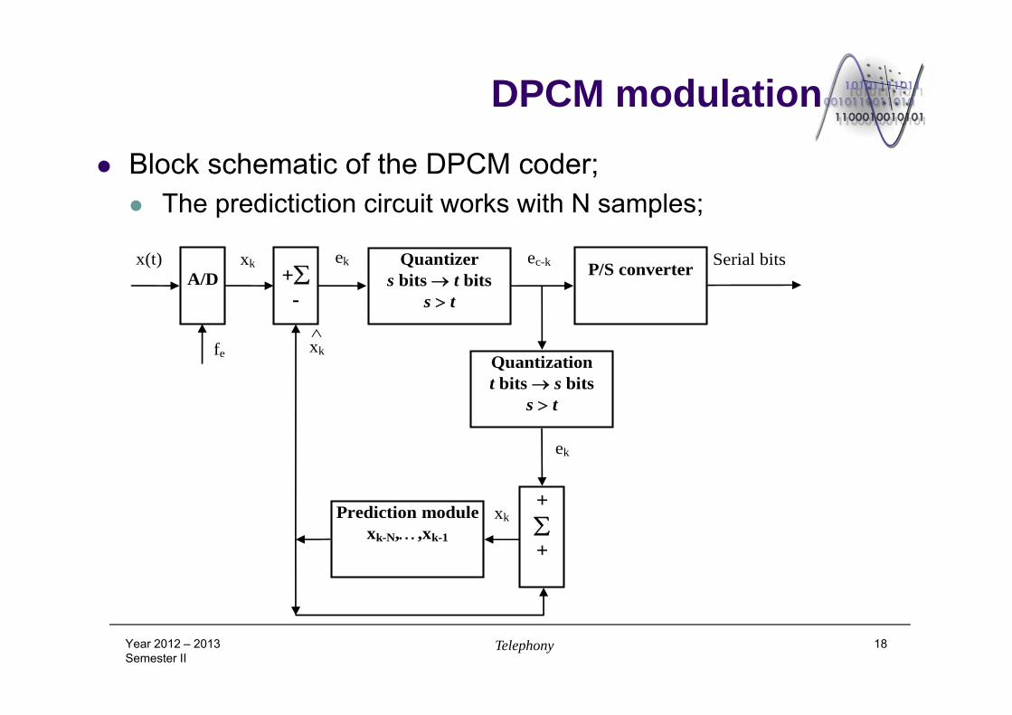
DPCM modulation
Block schematic of the DPCM coder; The predictiction circuit works with N samples;
Year 2012 – 2013Semester II
Telephony 18
A/D
fe
x(t)
xk
xk
+-
Quantizer s bits t bits
s t
P/S converter ek ec-k
+
+
Quantization t bits s bits
s t
Prediction modulexk-N,,xk-1
ek
Serial bits
xk
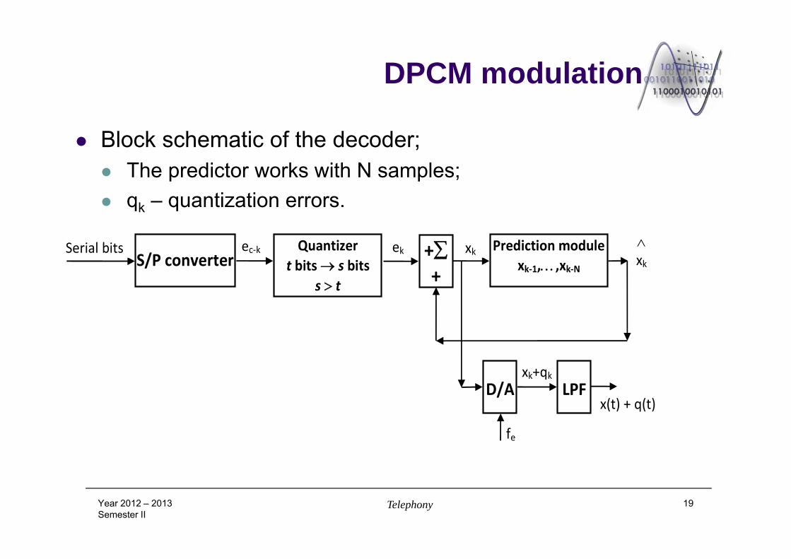
DPCM modulation
Block schematic of the decoder; The predictor works with N samples; qk – quantization errors.
Year 2012 – 2013Semester II
Telephony 19
fe
ec‐k Quantizert bits s bits
s t
S/P converterSerial bits
x(t) + q(t)
+ +
Prediction modulexk‐1,,xk‐N
ek xk
xk
D/A LPFxk+qk
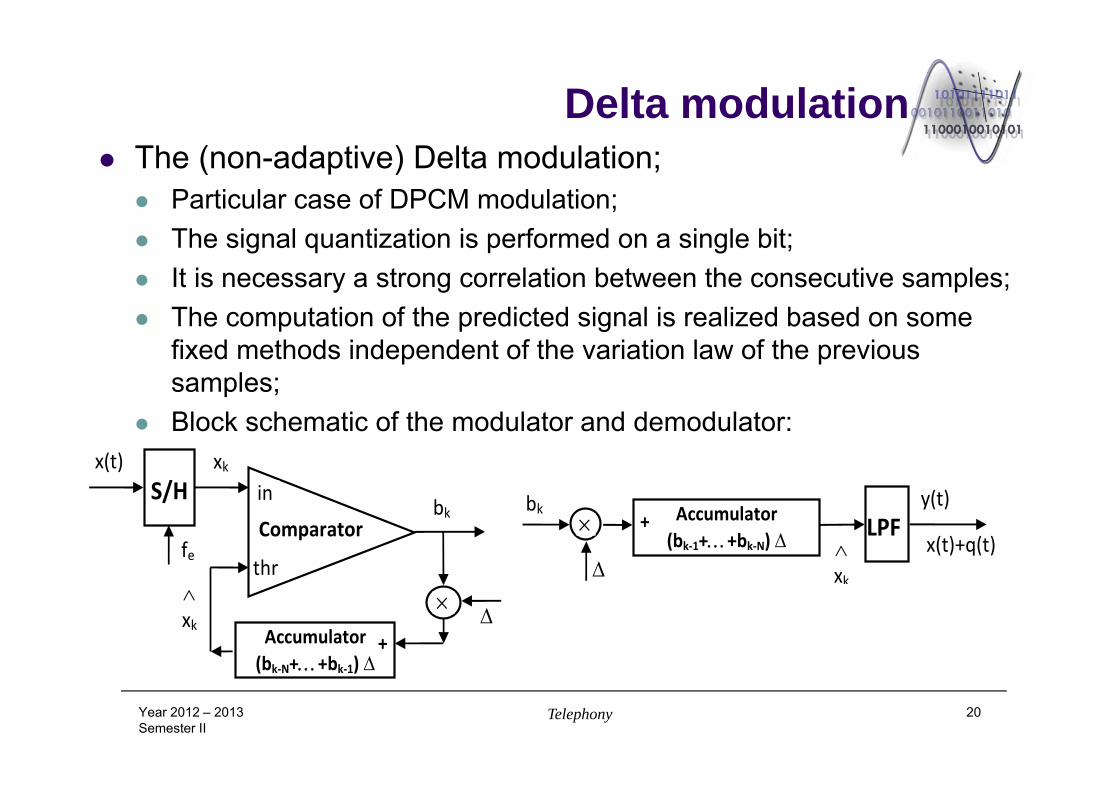
Delta modulation The (non-adaptive) Delta modulation;
Particular case of DPCM modulation; The signal quantization is performed on a single bit; It is necessary a strong correlation between the consecutive samples; The computation of the predicted signal is realized based on some
fixed methods independent of the variation law of the previous samples;
Block schematic of the modulator and demodulator:
Year 2012 – 2013Semester II
Telephony 20
bk Accumulator(bk‐1++bk‐N)
xk
+ LPFy(t)
x(t)+q(t)
S/H
fe
x(t) xk
bk
Accumulator(bk‐N++bk‐1)
Comparator
in
thr
xk+
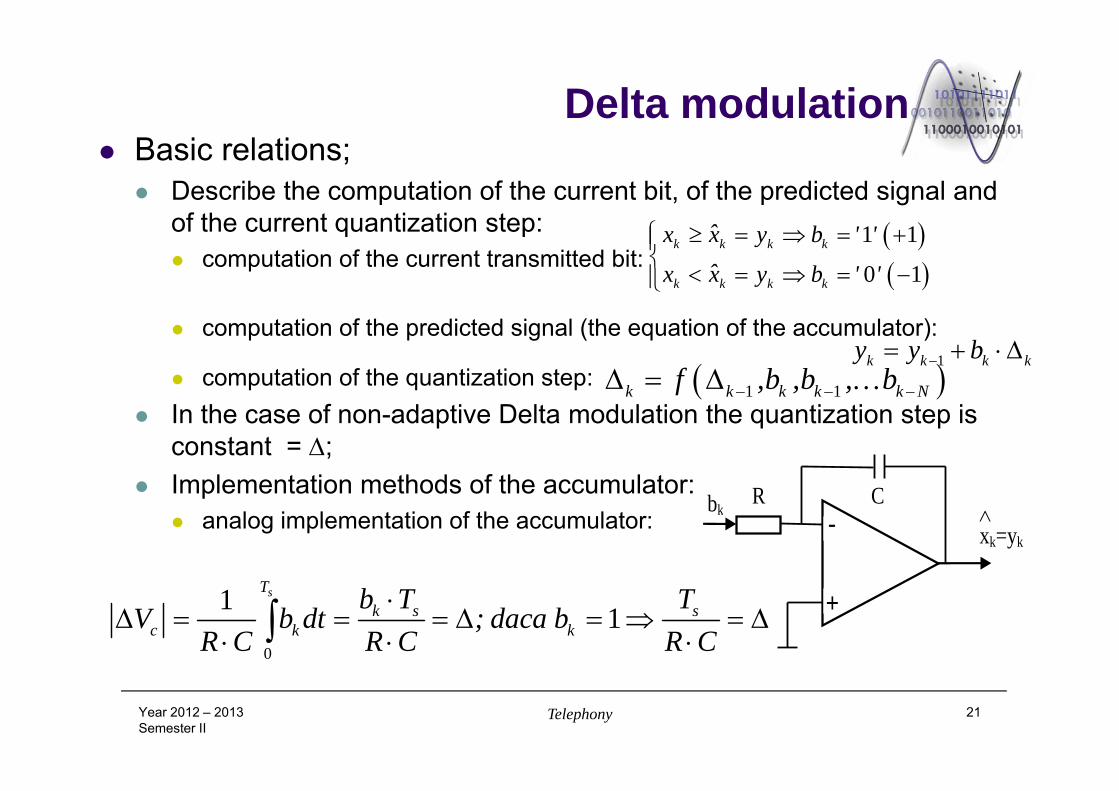
Delta modulation Basic relations;
Describe the computation of the current bit, of the predicted signal and of the current quantization step: computation of the current transmitted bit:
computation of the predicted signal (the equation of the accumulator):
computation of the quantization step: In the case of non-adaptive Delta modulation the quantization step is
constant = ; Implementation methods of the accumulator:
analog implementation of the accumulator:
Year 2012 – 2013Semester II
Telephony 21
Cbk -
+
xk=yk
R
1 1
0 1k k k k
k k k k
ˆx x y b ' 'ˆx x y b ' '
1k k k ky y b 1 1k k k k k Nf ,b ,b , b
0
1 1sT
k s sc k k
b T TV b dt ; daca b
R C R C R C
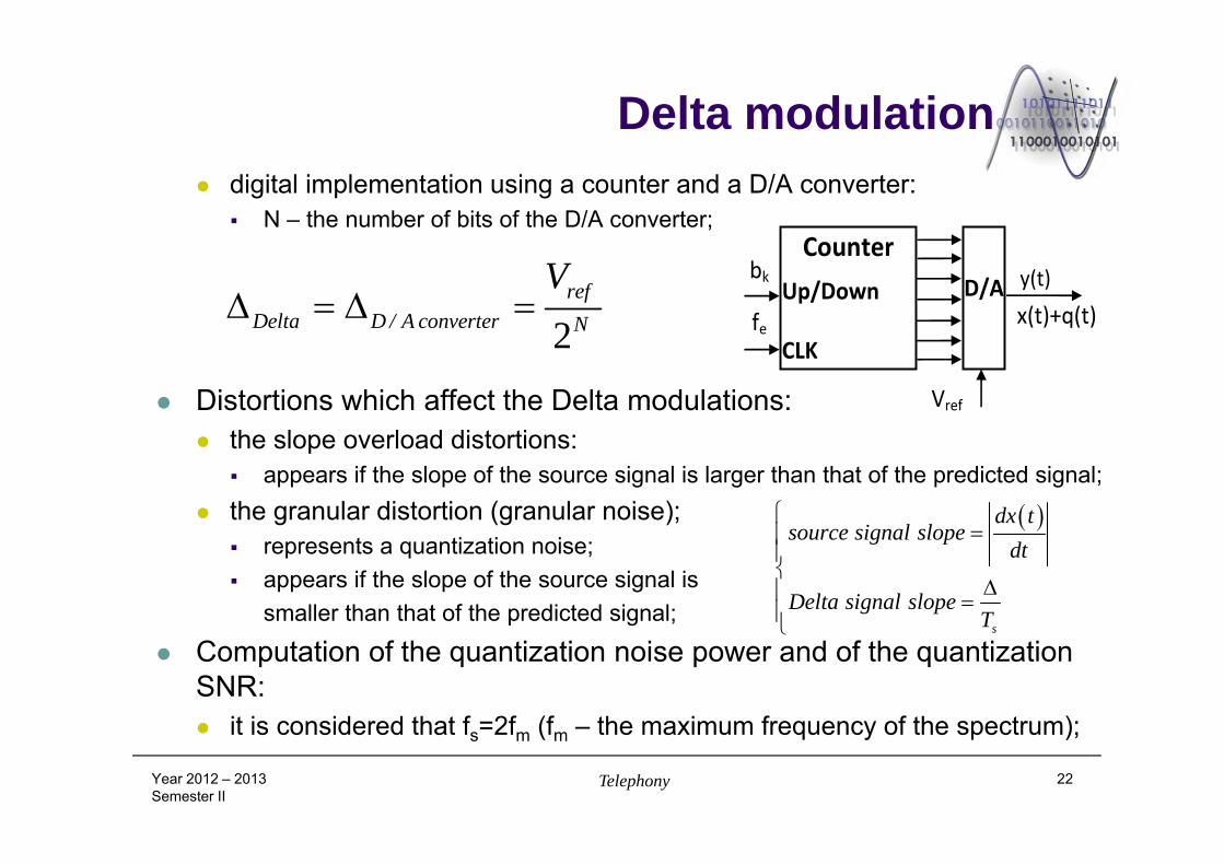
Delta modulation digital implementation using a counter and a D/A converter:
N – the number of bits of the D/A converter;
Distortions which affect the Delta modulations: the slope overload distortions:
appears if the slope of the source signal is larger than that of the predicted signal; the granular distortion (granular noise);
represents a quantization noise; appears if the slope of the source signal is
smaller than that of the predicted signal;
Computation of the quantization noise power and of the quantization SNR: it is considered that fs=2fm (fm – the maximum frequency of the spectrum);
Year 2012 – 2013Semester II
Telephony 22
bkCounter
Up/Down
CLK
D/A y(t)
x(t)+q(t)
Vref
fe2ref
Delta D / A converter N
V
s
dx tsource signal slope
dt
Delta signal slopeT
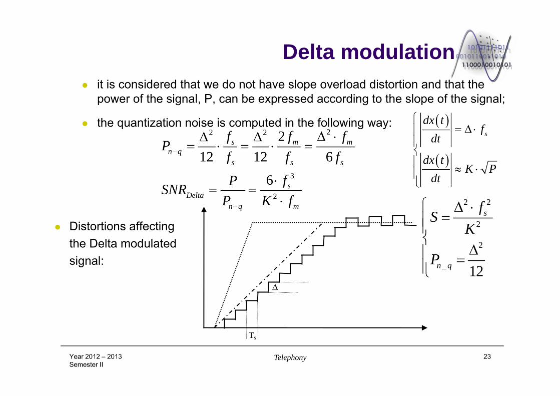
Delta modulation it is considered that we do not have slope overload distortion and that the
power of the signal, P, can be expressed according to the slope of the signal;
the quantization noise is computed in the following way:
Distortions affectingthe Delta modulatedsignal:
Year 2012 – 2013Semester II
Telephony 23
Ts
22 2
3
2
212 12 6
6
s m mn q
s s s
sDelta
n q m
f f fP
f f f
fPSNRP K f
s
dx tf
dt
dx tK P
dt
2 2
2
2
12
s
n_q
fS
K
P
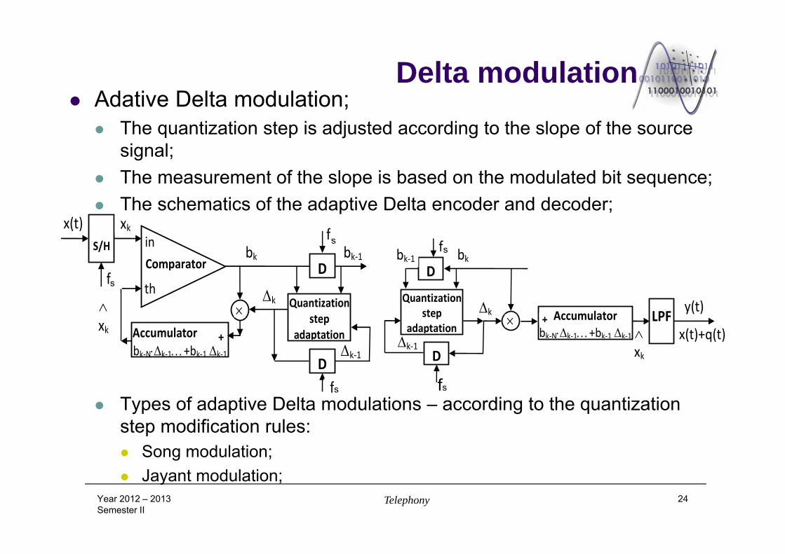
Delta modulation Adative Delta modulation;
The quantization step is adjusted according to the slope of the source signal;
The measurement of the slope is based on the modulated bit sequence; The schematics of the adaptive Delta encoder and decoder;
Types of adaptive Delta modulations – according to the quantization step modification rules: Song modulation; Jayant modulation;
Year 2012 – 2013Semester II
Telephony 24
S/H
fe
x(t) xk
bk
Accumulator bk‐Nk‐1+bk‐1 k‐1
k
Comparator in
th
xk +
D
fe
Quantizationstep
adaptation
Dfe
k‐1
bk‐1
bk
Accumulatorbk‐Nk‐1+bk‐1 k‐1
k
xk
+ LPF y(t)
x(t)+q(t)
D
fe bk‐1
Quantizationstep
adaptation
D k‐1
ss
s fs
s
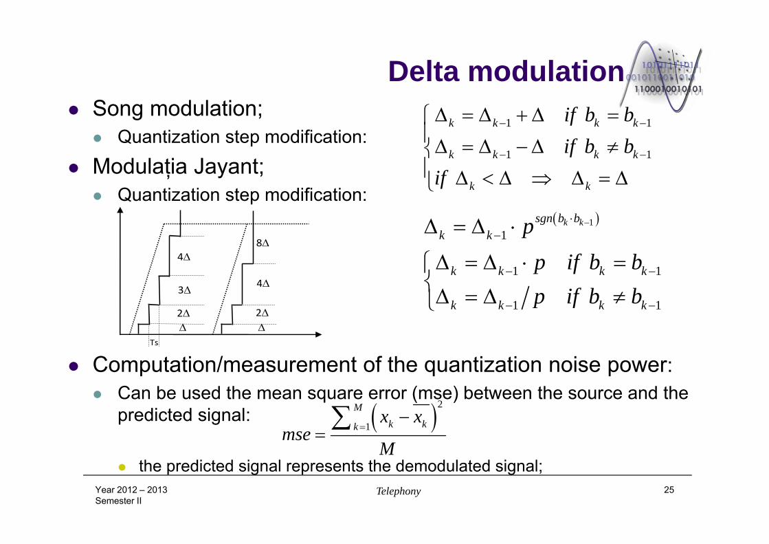
Delta modulation Song modulation;
Quantization step modification:
Modulaţia Jayant; Quantization step modification:
Computation/measurement of the quantization noise power: Can be used the mean square error (mse) between the source and the
predicted signal:
the predicted signal represents the demodulated signal;Year 2012 – 2013Semester II
Telephony 25
Ts
2
3
4
2
4
8
1 1
1 1
k k k k
k k k k
k k
if b bif b b
if
11
1 1
1 1
k ksgn b bk k
k k k k
k k k k
pp if b bp if b b
2
1
Mk kk
x xmse
M
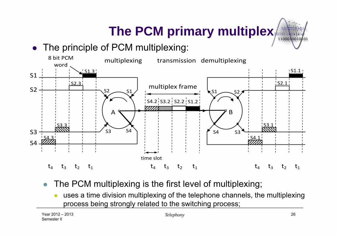
The PCM primary multiplex The principle of PCM multiplexing:
The PCM multiplexing is the first level of multiplexing; uses a time division multiplexing of the telephone channels, the multiplexing
process being strongly related to the switching process;Year 2012 – 2013Semester II
Telephony 26
S1
S2
S3
S4
t4 t3 t2 t1 t4 t3 t2 t1 t4 t3 t2 t1
S4.3
S3.3
S2.3
S1.3
S4.2 S3.2 S2.2 S1.2
time slot
multiplex frame
S4.1
S3.1
S2.1
S1.1
multiplexing transmission demultiplexing8 bit PCM word
A B
S1S2
S3 S4
S2S1
S4 S3
The PCM primary multiplex
to each 8 bit PCM word is allocated a time interval – time slot, interval in which the bits are transmitted;
PCM words generated by different sources are interleaved, a separate time slot corresponding to each word;
the bit rate assigned to the multiplex frame must be N times larger than the bit rate assigned to one of the multiplexed channels, N being the number of the multiplexed channels;
the demultiplexing implies the identification of the time slots assigned to different channels and the transmission to the destination of the words extracted from the time slots, using a bit rate characteristic to the terminal equipment;
Year 2012 – 2013Semester II
Telephony 27
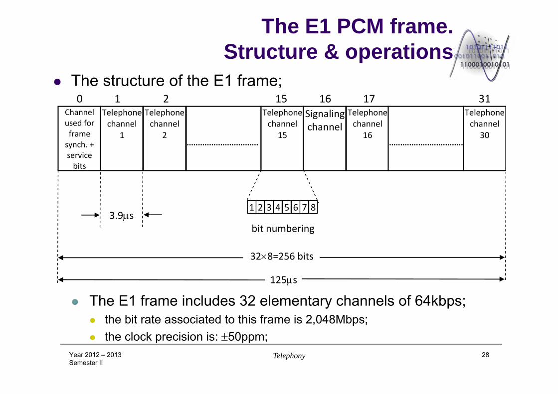
The E1 PCM frame. Structure & operations
The structure of the E1 frame;
The E1 frame includes 32 elementary channels of 64kbps; the bit rate associated to this frame is 2,048Mbps; the clock precision is: 50ppm;
Year 2012 – 2013Semester II
Telephony 28
Channel used for frame synch. + service bits
Telephone channel
1
Telephone channel
2
................................
Telephone channel
15
Signalingchannel
Telephone channel
16
.................................
Telephone channel
30
0 1 2 15 16 17 31
3.9s
125s
328=256 bits
bit numbering
1 2 3 4 5 6 7 8
The E1 PCM frame. Structure & operations
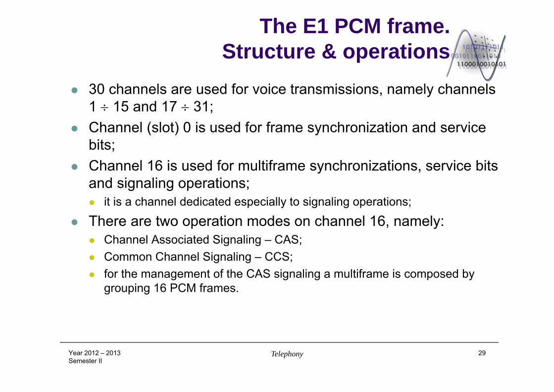
30 channels are used for voice transmissions, namely channels 1 15 and 17 31;
Channel (slot) 0 is used for frame synchronization and service bits;
Channel 16 is used for multiframe synchronizations, service bits and signaling operations; it is a channel dedicated especially to signaling operations;
There are two operation modes on channel 16, namely: Channel Associated Signaling – CAS; Common Channel Signaling – CCS; for the management of the CAS signaling a multiframe is composed by
grouping 16 PCM frames.
Year 2012 – 2013Semester II
Telephony 29
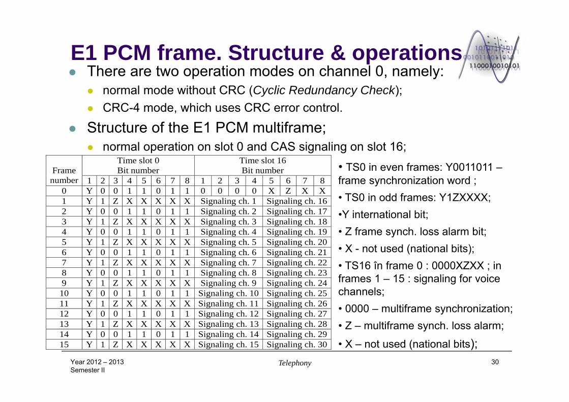
E1 PCM frame. Structure & operations There are two operation modes on channel 0, namely:
normal mode without CRC (Cyclic Redundancy Check); CRC-4 mode, which uses CRC error control.
Structure of the E1 PCM multiframe; normal operation on slot 0 and CAS signaling on slot 16;
Year 2012 – 2013Semester II
Telephony 30
• TS0 in even frames: Y0011011 –frame synchronization word ;• TS0 in odd frames: Y1ZXXXX; •Y international bit;• Z frame synch. loss alarm bit;• X - not used (national bits);• TS16 în frame 0 : 0000XZXX ; in frames 1 – 15 : signaling for voice channels;• 0000 – multiframe synchronization;• Z – multiframe synch. loss alarm;
• X – not used (national bits);
Frame number
Time slot 0 Bit number
Time slot 16 Bit number
1 2 3 4 5 6 7 8 1 2 3 4 5 6 7 8 0 Y 0 0 1 1 0 1 1 0 0 0 0 X Z X X 1 Y 1 Z X X X X X Signaling ch. 1 Signaling ch. 16 2 Y 0 0 1 1 0 1 1 Signaling ch. 2 Signaling ch. 17 3 Y 1 Z X X X X X Signaling ch. 3 Signaling ch. 18 4 Y 0 0 1 1 0 1 1 Signaling ch. 4 Signaling ch. 19 5 Y 1 Z X X X X X Signaling ch. 5 Signaling ch. 20 6 Y 0 0 1 1 0 1 1 Signaling ch. 6 Signaling ch. 21 7 Y 1 Z X X X X X Signaling ch. 7 Signaling ch. 22 8 Y 0 0 1 1 0 1 1 Signaling ch. 8 Signaling ch. 23 9 Y 1 Z X X X X X Signaling ch. 9 Signaling ch. 24 10 Y 0 0 1 1 0 1 1 Signaling ch. 10 Signaling ch. 25 11 Y 1 Z X X X X X Signaling ch. 11 Signaling ch. 26 12 Y 0 0 1 1 0 1 1 Signaling ch. 12 Signaling ch. 27 13 Y 1 Z X X X X X Signaling ch. 13 Signaling ch. 28 14 Y 0 0 1 1 0 1 1 Signaling ch. 14 Signaling ch. 29 15 Y 1 Z X X X X X Signaling ch. 15 Signaling ch. 30
The E1 PCM frame.Structure & operations
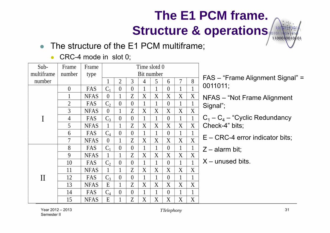
The structure of the E1 PCM multiframe; CRC-4 mode in slot 0;
Year 2012 – 2013Semester II
TTelephony 31
FAS – “Frame Alignment Signal” = 0011011;
NFAS – “Not Frame Alignment Signal”;
C1 – C4 – “Cyclic Redundancy Check-4” bits;
E – CRC-4 error indicator bits;
Z – alarm bit;
X – unused bits.
Sub-multiframe
number
Frame number
Frame type
Time slotd 0 Bit number
1 2 3 4 5 6 7 8 I
0 FAS C1 0 0 1 1 0 1 1 1 NFAS 0 1 Z X X X X X 2 FAS C2 0 0 1 1 0 1 1 3 NFAS 0 1 Z X X X X X 4 FAS C3 0 0 1 1 0 1 1 5 NFAS 1 1 Z X X X X X 6 FAS C4 0 0 1 1 0 1 1 7 NFAS 0 1 Z X X X X X
II
8 FAS C1 0 0 1 1 0 1 1 9 NFAS 1 1 Z X X X X X
10 FAS C2 0 0 1 1 0 1 1 11 NFAS 1 1 Z X X X X X 12 FAS C3 0 0 1 1 0 1 1 13 NFAS E 1 Z X X X X X 14 FAS C4 0 0 1 1 0 1 1 15 NFAS E 1 Z X X X X X
The E1 PCM frame.Structure & operations
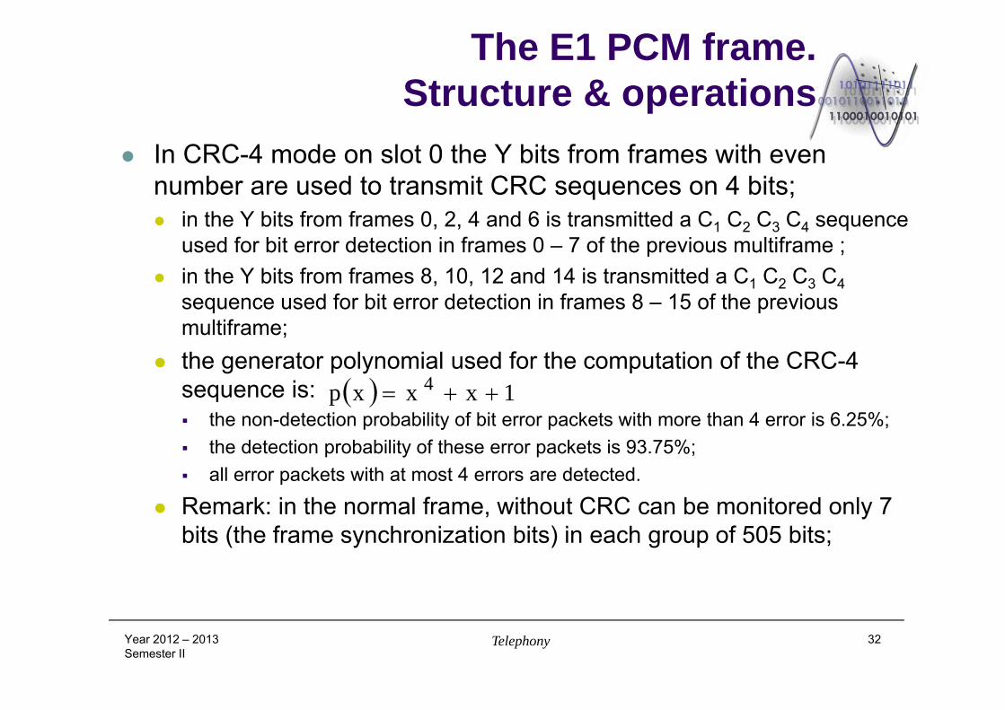
In CRC-4 mode on slot 0 the Y bits from frames with even number are used to transmit CRC sequences on 4 bits; in the Y bits from frames 0, 2, 4 and 6 is transmitted a C1 C2 C3 C4 sequence
used for bit error detection in frames 0 – 7 of the previous multiframe ; in the Y bits from frames 8, 10, 12 and 14 is transmitted a C1 C2 C3 C4
sequence used for bit error detection in frames 8 – 15 of the previous multiframe;
the generator polynomial used for the computation of the CRC-4 sequence is: the non-detection probability of bit error packets with more than 4 error is 6.25%; the detection probability of these error packets is 93.75%; all error packets with at most 4 errors are detected.
Remark: in the normal frame, without CRC can be monitored only 7 bits (the frame synchronization bits) in each group of 505 bits;
Year 2012 – 2013Semester II
Telephony 32
1xxxp 4
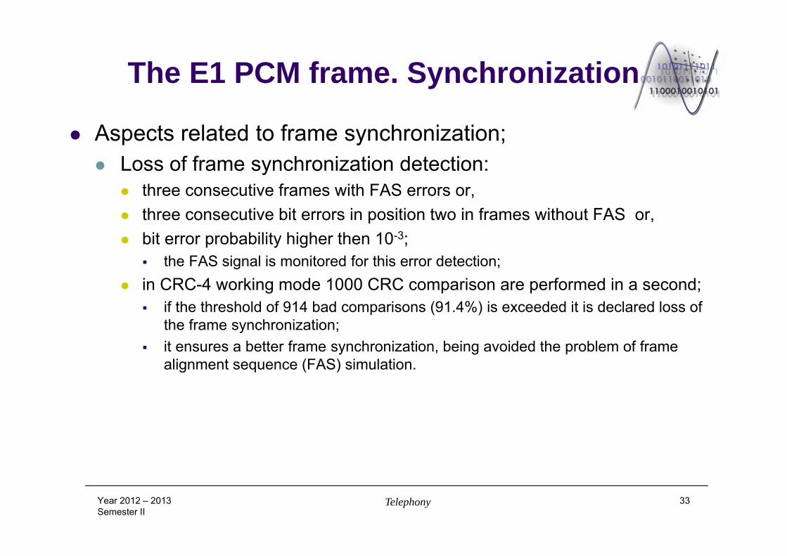
The E1 PCM frame. Synchronization
Aspects related to frame synchronization; Loss of frame synchronization detection:
three consecutive frames with FAS errors or, three consecutive bit errors in position two in frames without FAS or, bit error probability higher then 10-3;
the FAS signal is monitored for this error detection; in CRC-4 working mode 1000 CRC comparison are performed in a second;
if the threshold of 914 bad comparisons (91.4%) is exceeded it is declared loss of the frame synchronization;
it ensures a better frame synchronization, being avoided the problem of frame alignment sequence (FAS) simulation.
Year 2012 – 2013Semester II
Telephony 33
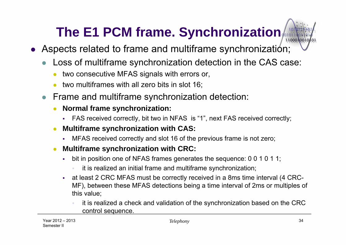
The E1 PCM frame. Synchronization Aspects related to frame and multiframe synchronization; Loss of multiframe synchronization detection in the CAS case:
two consecutive MFAS signals with errors or, two multiframes with all zero bits in slot 16;
Frame and multiframe synchronization detection: Normal frame synchronization:
FAS received correctly, bit two in NFAS is “1”, next FAS received correctly; Multiframe synchronization with CAS:
MFAS received correctly and slot 16 of the previous frame is not zero; Multiframe synchronization with CRC:
bit in position one of NFAS frames generates the sequence: 0 0 1 0 1 1; it is realized an initial frame and multiframe synchronization;
at least 2 CRC MFAS must be correctly received in a 8ms time interval (4 CRC-MF), between these MFAS detections being a time interval of 2ms or multiples of this value; it is realized a check and validation of the synchronization based on the CRC
control sequence.Year 2012 – 2013Semester II
Telephony 34
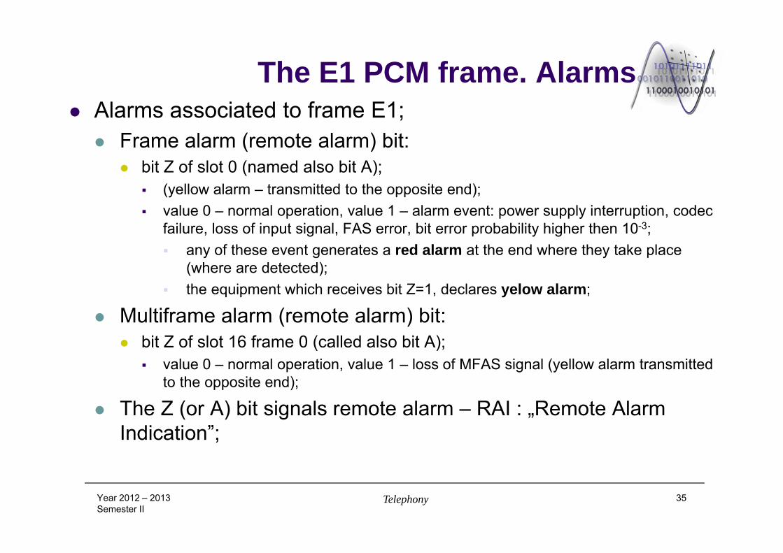
The E1 PCM frame. Alarms Alarms associated to frame E1; Frame alarm (remote alarm) bit:
bit Z of slot 0 (named also bit A); (yellow alarm – transmitted to the opposite end); value 0 – normal operation, value 1 – alarm event: power supply interruption, codec
failure, loss of input signal, FAS error, bit error probability higher then 10-3; any of these event generates a red alarm at the end where they take place
(where are detected); the equipment which receives bit Z=1, declares yelow alarm;
Multiframe alarm (remote alarm) bit: bit Z of slot 16 frame 0 (called also bit A);
value 0 – normal operation, value 1 – loss of MFAS signal (yellow alarm transmitted to the opposite end);
The Z (or A) bit signals remote alarm – RAI : „Remote Alarm Indication”;
Year 2012 – 2013Semester II
Telephony 35
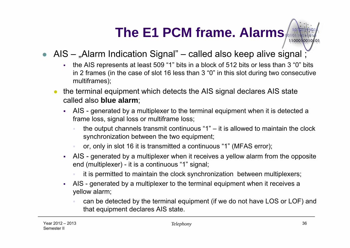
The E1 PCM frame. Alarms AIS – „Alarm Indication Signal” – called also keep alive signal ;
the AIS represents at least 509 “1” bits in a block of 512 bits or less than 3 “0” bits in 2 frames (in the case of slot 16 less than 3 “0” in this slot during two consecutive multiframes);
the terminal equipment which detects the AIS signal declares AIS state called also blue alarm; AIS - generated by a multiplexer to the terminal equipment when it is detected a
frame loss, signal loss or multiframe loss; the output channels transmit continuous “1” – it is allowed to maintain the clock
synchronization between the two equipment; or, only in slot 16 it is transmitted a continuous “1” (MFAS error);
AIS - generated by a multiplexer when it receives a yellow alarm from the opposite end (multiplexer) - it is a continuous “1” signal; it is permitted to maintain the clock synchronization between multiplexers;
AIS - generated by a multiplexer to the terminal equipment when it receives a yellow alarm; can be detected by the terminal equipment (if we do not have LOS or LOF) and
that equipment declares AIS state.
Year 2012 – 2013Semester II
Telephony 36
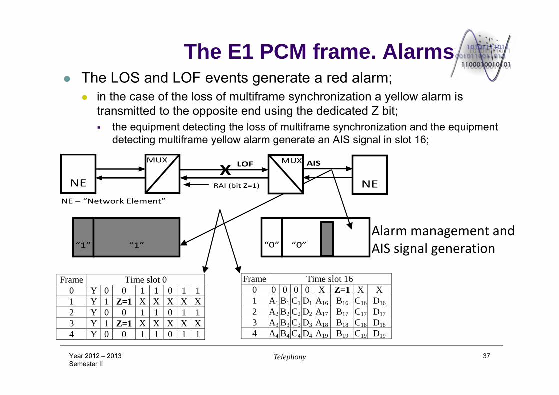
The E1 PCM frame. Alarms The LOS and LOF events generate a red alarm;
in the case of the loss of multiframe synchronization a yellow alarm is transmitted to the opposite end using the dedicated Z bit; the equipment detecting the loss of multiframe synchronization and the equipment
detecting multiframe yellow alarm generate an AIS signal in slot 16;
Year 2012 – 2013Semester II
Telephony 37
Alarm management and AIS signal generation
Frame Time slot 0 0 Y 0 0 1 1 0 1 11 Y 1 Z=1 X X X X X2 Y 0 0 1 1 0 1 13 Y 1 Z=1 X X X X X4 Y 0 0 1 1 0 1 1
Frame Time slot 16 0 0 0 0 0 X Z=1 X X 1 A1 B1 C1 D1 A16 B16 C16 D162 A2 B2 C2 D2 A17 B17 C17 D173 A3 B3 C3 D3 A18 B18 C18 D184 A4 B4 C4 D4 A19 B19 C19 D19
“1”
“1”
“0”
“0”
NE
NE
MUX
MUX
RAI (bit Z=1)
LOF AIS X
NE – “Network Element”
The T1 PCM frame. Structure & operations
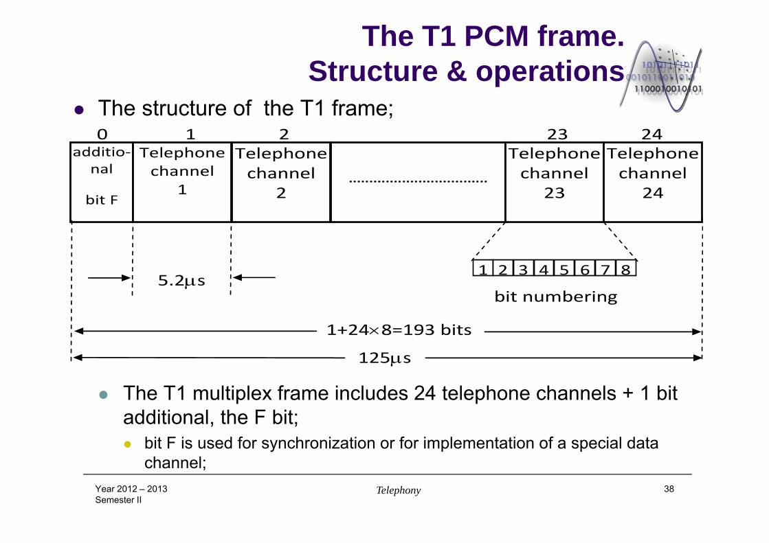
The structure of the T1 frame;
The T1 multiplex frame includes 24 telephone channels + 1 bit additional, the F bit; bit F is used for synchronization or for implementation of a special data
channel;Year 2012 – 2013Semester II
Telephony 38
additio‐nal
bit F
Telephone channel
1
Telephone channel
2
..................................
Telephone channel
23
Telephone channel
24
0 1 2 23 24
5.2s
125s
1+248=193 bits
bit numbering
1 2 3 4 5 6 7 8
The T1 PCM frame. Structure & operations
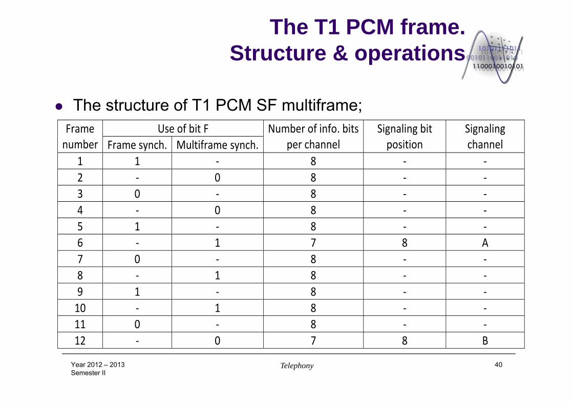
Types of T1 multiframes: The Supper Frame (SF);
composed of 12 frames; has no separate time slot for synchronization or signaling;
the frame and the multiframe synchronization is accomplished with the help of the supplementary F bit;
for channel assigned signaling it is used the last bit of each sixth frame : A – B type signaling; this technique is called bit robbing;
for CCS signaling is used the slot 24 of the T1 frame; in the case of SF frame the yellow alarm is transmitted by setting the bit no. 2 of
each slot to 0;
Year 2012 – 2013Semester II
Telephony 39
The T1 PCM frame. Structure & operations
The structure of T1 PCM SF multiframe;
Year 2012 – 2013Semester II
Telephony 40
Frame number
Use of bit F Number of info. bitsper channel
Signaling bit position
Signaling channel Frame synch. Multiframe synch.
1 1 ‐ 8 ‐ ‐ 2 ‐ 0 8 ‐ ‐ 3 0 ‐ 8 ‐ ‐ 4 ‐ 0 8 ‐ ‐ 5 1 ‐ 8 ‐ ‐ 6 ‐ 1 7 8 A 7 0 ‐ 8 ‐ ‐ 8 ‐ 1 8 ‐ ‐ 9 1 ‐ 8 ‐ ‐ 10 ‐ 1 8 ‐ ‐ 11 0 ‐ 8 ‐ ‐ 12 ‐ 0 7 8 B
The T1 PCM frame. Structure & operations
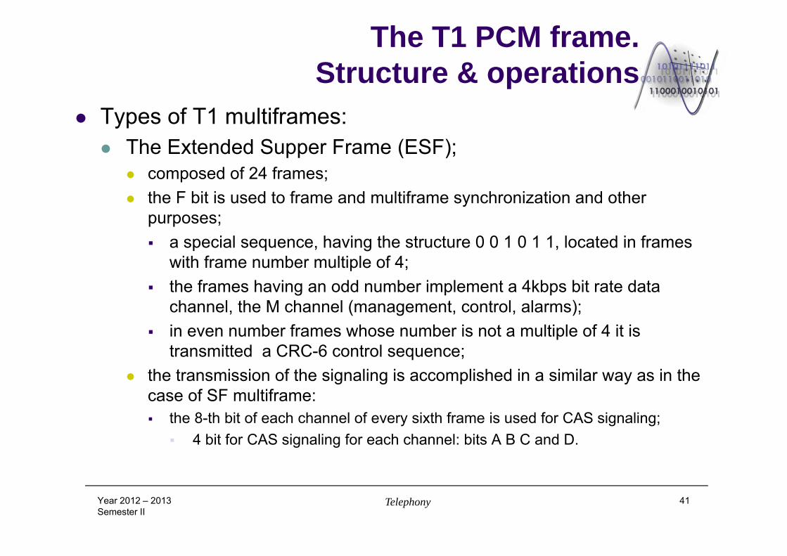
Types of T1 multiframes: The Extended Supper Frame (ESF);
composed of 24 frames; the F bit is used to frame and multiframe synchronization and other
purposes; a special sequence, having the structure 0 0 1 0 1 1, located in frames
with frame number multiple of 4; the frames having an odd number implement a 4kbps bit rate data
channel, the M channel (management, control, alarms); in even number frames whose number is not a multiple of 4 it is
transmitted a CRC-6 control sequence; the transmission of the signaling is accomplished in a similar way as in the
case of SF multiframe: the 8-th bit of each channel of every sixth frame is used for CAS signaling;
4 bit for CAS signaling for each channel: bits A B C and D.
Year 2012 – 2013Semester II
Telephony 41
The T1 PCM frame. Structure & operations
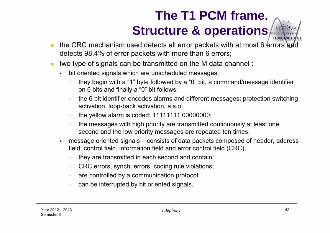
the CRC mechanism used detects all error packets with at most 6 errors and detects 98.4% of error packets with more than 6 errors;
two type of signals can be transmitted on the M data channel : bit oriented signals which are unscheduled messages;
they begin with a “1” byte followed by a “0” bit, a command/message identifier on 6 bits and finally a “0” bit follows;
the 6 bit identifier encodes alarms and different messages: protection switching activation, loop-back activation, a.s.o.
the yellow alarm is coded: 11111111 00000000; the messages with high priority are transmitted continuously at least one
second and the low priority messages are repeated ten times; message oriented signals – consists of data packets composed of header, address
field, control field, information field and error control field (CRC); they are transmitted in each second and contain: CRC errors, synch. errors, coding rule violations; are controlled by a communication protocol; can be interrupted by bit oriented signals.
Year 2012 – 2013Semester II
Telephony 42
The T1 PCM frame.Structure & operations
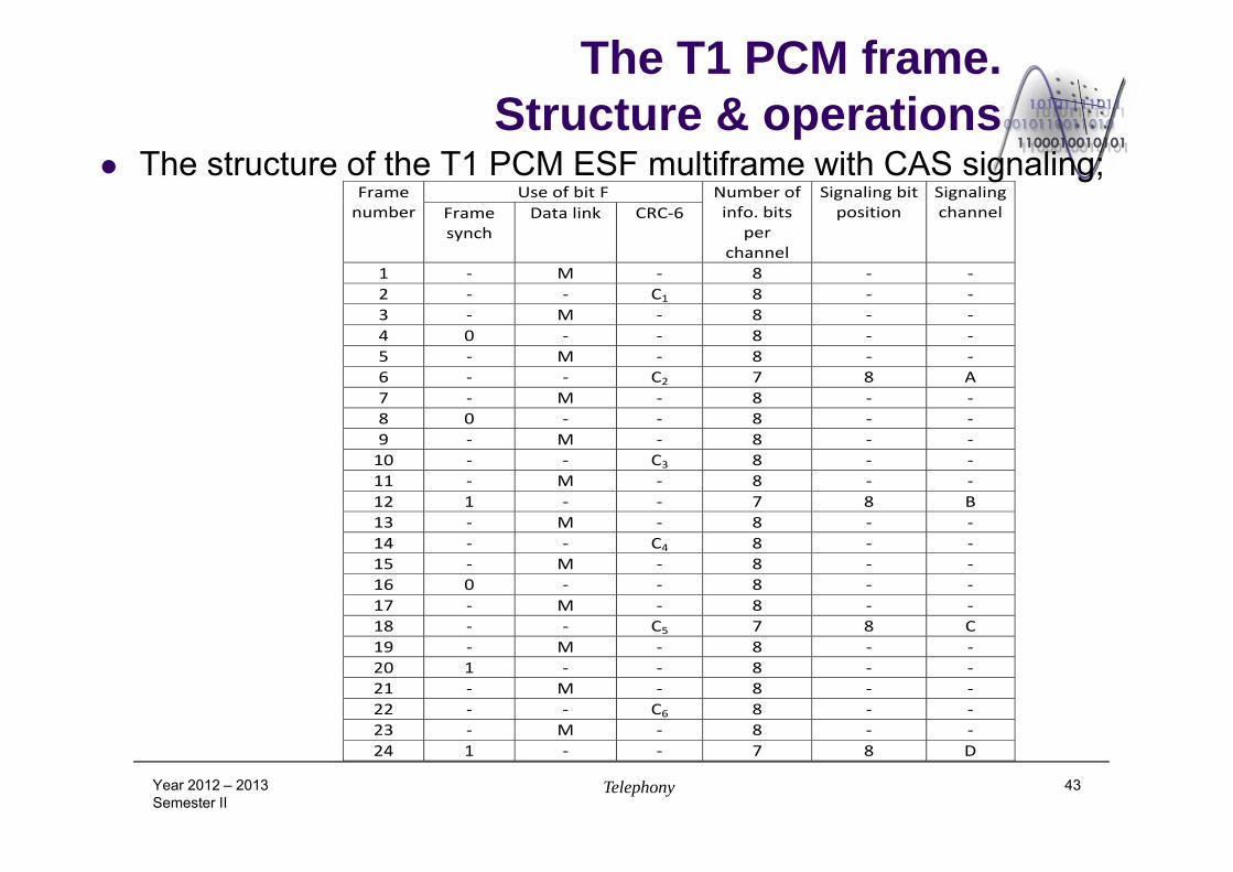
The structure of the T1 PCM ESF multiframe with CAS signaling;
Year 2012 – 2013Semester II
Telephony 43
Frame number
Use of bit F Number of info. bits
per channel
Signaling bitposition
Signaling channel Frame
synch Data link CRC‐6
1 ‐ M ‐ 8 ‐ ‐ 2 ‐ ‐ C1 8 ‐ ‐ 3 ‐ M ‐ 8 ‐ ‐ 4 0 ‐ ‐ 8 ‐ ‐ 5 ‐ M ‐ 8 ‐ ‐ 6 ‐ ‐ C2 7 8 A 7 ‐ M ‐ 8 ‐ ‐ 8 0 ‐ ‐ 8 ‐ ‐ 9 ‐ M ‐ 8 ‐ ‐ 10 ‐ ‐ C3 8 ‐ ‐ 11 ‐ M ‐ 8 ‐ ‐ 12 1 ‐ ‐ 7 8 B 13 ‐ M ‐ 8 ‐ ‐ 14 ‐ ‐ C4 8 ‐ ‐ 15 ‐ M ‐ 8 ‐ ‐ 16 0 ‐ ‐ 8 ‐ ‐ 17 ‐ M ‐ 8 ‐ ‐ 18 ‐ ‐ C5 7 8 C 19 ‐ M ‐ 8 ‐ ‐ 20 1 ‐ ‐ 8 ‐ ‐ 21 ‐ M ‐ 8 ‐ ‐ 22 ‐ ‐ C6 8 ‐ ‐ 23 ‐ M ‐ 8 ‐ ‐ 24 1 ‐ ‐ 7 8 D
The T1 PCM frame. Alarms The T1 alarms (shortly); OOF (“Out Of Frame Condition”): 2 of 4, 2 of 5 or 3 of 5
synchronization bits are erroneous; Red CFA (“Carrier Failure Alarm”): OOF for 2.5s; end of this
state: no OOF for 1s; Yellow CFA – yellow alarm transmitted to the opposite end; LOS (“Los Of Signal”): no impulse detected in a window of
175+/-75 impulse periods (100 – 250 bits);
Year 2012 – 2013Semester II
Telephony 44
Line interface of the primary multiplex Transmission of the E1 frame; 4 wire full duplex transmission;
AMI (Alternate Mark Inversion) coding; the “0” bit is coded with a 0V level and the “1” bits are alternatively coded with A
impulses; this code has no DC component (it is avoided the saturation of the separation
transformer’s core); has relatively narrow bandwidth; simple decoding; reduced synchronization capability;
it is replaced with a HDB3 (High-Density-Bipolar-3 Zeros) coding; this code replaces groups of 4 zeros with violations of AMI coding rule – it is
ensured also a reduced level of the DC component.
Year 2012 – 2013Semester II
Telephony 45
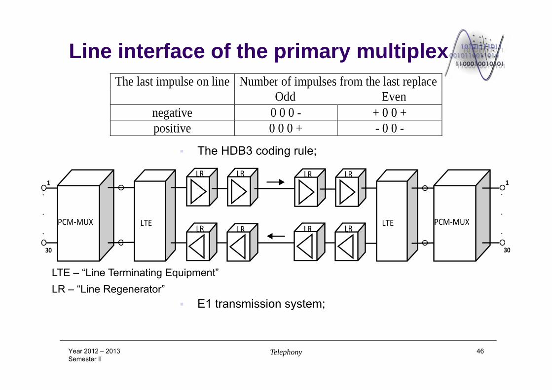
Line interface of the primary multiplex
The HDB3 coding rule;
E1 transmission system;
Year 2012 – 2013Semester II
Telephony 46
PCM‐MUX LTE
LR1
30
.
.
.
LR LRLR
LTE PCM‐MUX
1
30
.
.
. LRLR LRLR
LTE – “Line Terminating Equipment”LR – “Line Regenerator”
The last impulse on line Number of impulses from the last replace Odd Even
negative 0 0 0 - + 0 0 + positive 0 0 0 + - 0 0 -
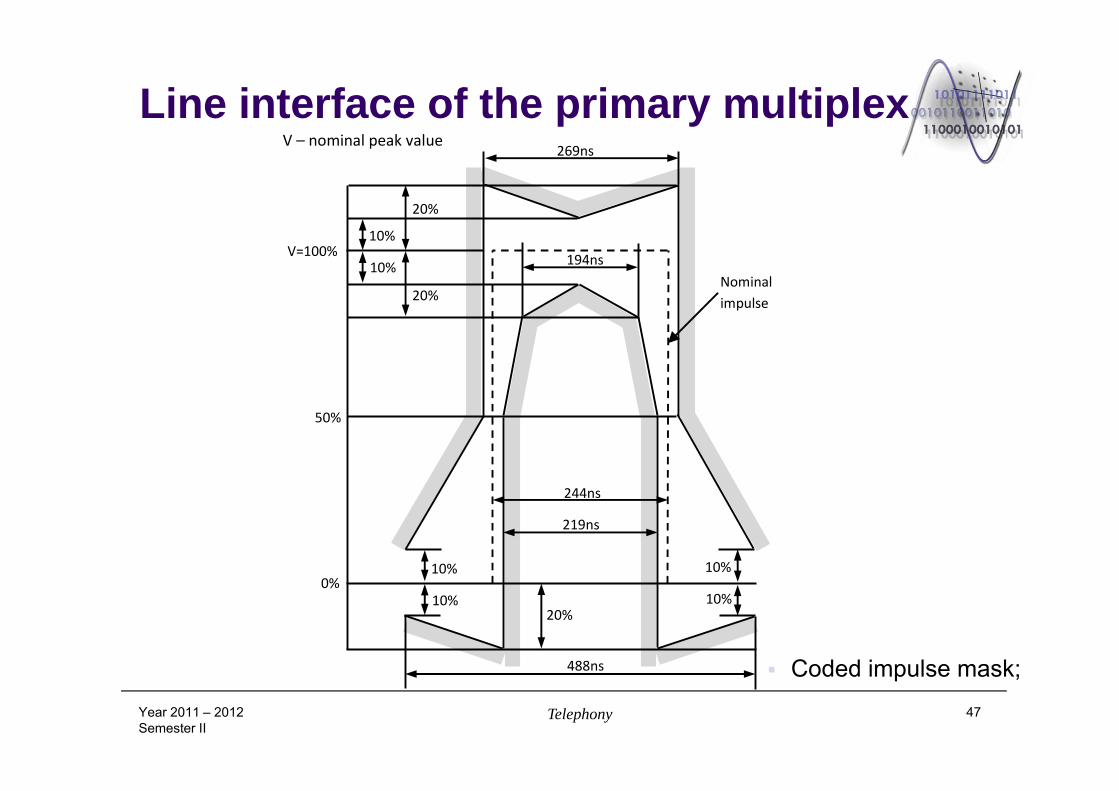
Line interface of the primary multiplex
Coded impulse mask;
Year 2011 – 2012Semester II
Telephony 47
V=100%
V – nominal peak value
Nominalimpulse
50%
0%10%
10%
10%
10%
20%
20%
20%
269ns
194ns
219ns
244ns
488ns
10%
10%
Line interface of the primary multiplex (E1) line interface parameters:
Nominal bit rate: 2048kbps; Precision of the nominal bit rate: at least 50ppm; Line code: HDB3; Frame structure; Transmission medium / Number of pairs in each direction;
Coaxial; Twisted pairs; 1 cable / 1 pair for each transmission direction; Load impedance: 75 (coaxial), 120 (twisted pair); Peak amplitude: 2.37V – 3V; Power level and power spectral mask; Impulse nominal duration: 244ns; Ration of positive and negative amplitudes: 0.95 – 1.05; Ratio of positive/negative pulse duration: 0.95 – 1.05; Maximum peak to peak jitter; DC power: has to be as low as possible;Year 2012 – 2013Semester II
Telephony 48
Line interface of the primary multiplex T1 interface specific characteristics: Transmission of T1 frames is similar with the transmission of E1
frames; 4 wire full duplex with regenerators after each 1.5km cable length;
B8ZS (Bipolar with 8 Zero Substitution) line coding; AMI type cod which replaces the groups of 8 consecutive zero bits with a
coded sequence having the structure: 0 0 0 0 V 1 0 V 1: 4 “0” bits, a violation of the AMI coding rule, followed by “1” “0” normally coded and
after that a new violation of the AMI coding rule and finally a “1” normally coded.
Year 2012 – 2013Semester II
Telephony 49
Terminal – multiplexer interface There are defined two types of interfaces between the local
equipment (terminal - multiplexer); These correspond to two transmission strategy of data
transmission and synchronization; Codirectional interfaces;
correspond to the case when each equipment transmits the data together with his own synchronization signal; all equipment must have the same clock synchronized from an external source;
Contradirectional interfaces; the multiplexer transmit the synchronization information for both
transmission directions; it is not necessary an external synchronization source;
Year 2011 – 2012Semester II
Telephony 50
Terminal – multiplexer interface Codirectional interfaces; A complex signal, combining both the information and the
synchronization signals (bit clock and byte clock) is transmitted between the connected equipment;
A single channel composed of a pair of wire is used in each directions; separation transformers are usually used.
Precision of the clock signal: at least 100ppm; The clock generator of each equipment (multiplexer or terminal
equipment) is synchronized with an external reference clock;
Year 2011 – 2012Semester II
Telephony 51
Terminal – multiplexer interface
Year 2012 – 2013Semester II
Telephony 52
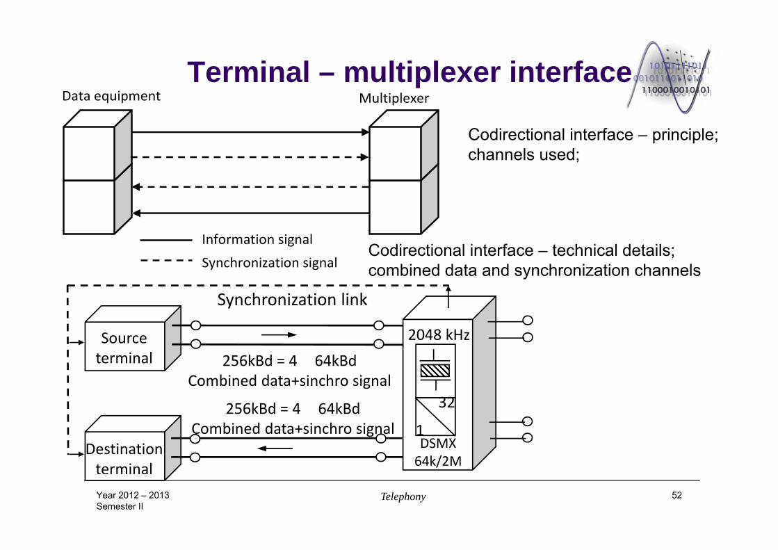
Codirectional interface – principle; channels used;
Codirectional interface – technical details; combined data and synchronization channels
Multiplexer Data equipment
Information signal
Synchronization signal
Sourceterminal
Destination terminal
Synchronization link
32
1DSMX64k/2M
2048 kHz256kBd = 4 64kBd
Combined data+sinchro signal
256kBd = 4 64kBdCombined data+sinchro signal
Terminal – multiplexer interface Codirectional interface – the coding rule;
step 1: the period corresponding to the 64kbps rate is split in 4 unit intervals; step 2: a binary “1” (64kbps rate) is coded as a block of 4 binary symbols
(each having a period 4 times smaller): “1 1 0 0”; “0” represents 0V; step 3: a binary “0” (64kbps rate) is coded as a block of 4 binary symbols
(each having a period 4 times smaller): “1 0 1 0”; step 4: the coded data signal is converted into a 3 level signal by alternating
the polarity of consecutive blocks of 4 symbols; step 5: the alternation of the polarity of the blocks is violated every 8th block,
meaning the position corresponding to bit 8 in a byte; in this way can be realized the byte level synchronization between the two
equipment.
Year 2012 – 2013Semester II
Telephony 53
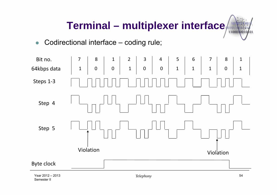
Terminal – multiplexer interface Codirectional interface – coding rule;
Year 2012 – 2013Semester II
Telephony 54
Bit no.
64kbps data 1 0 0 1 0 0 1 1 1 0 1
7 8 1 2 3 4 5 6 7 8 1
Steps 1‐3
Step 4
Step 5
Violation Violation
Byte clock
Terminal – multiplexer interface Contradirectional interfaces; Both the data signal and the synchronization signal is
transmitted between equipment; The synchronization signal is transmitted from multiplexer to
terminal equipment; There are necessary two channels, each on a pair of wire, in
both directions: data and synchronization bit clock and byte clock;
Precision of the clock signal: at least 100 ppm; It is not necessary an external reference clock;
Year 2012 – 2013Semester II
Telephony 55
Terminal – multiplexer interface
Year 2012 – 2013Semester II
Telephony 56
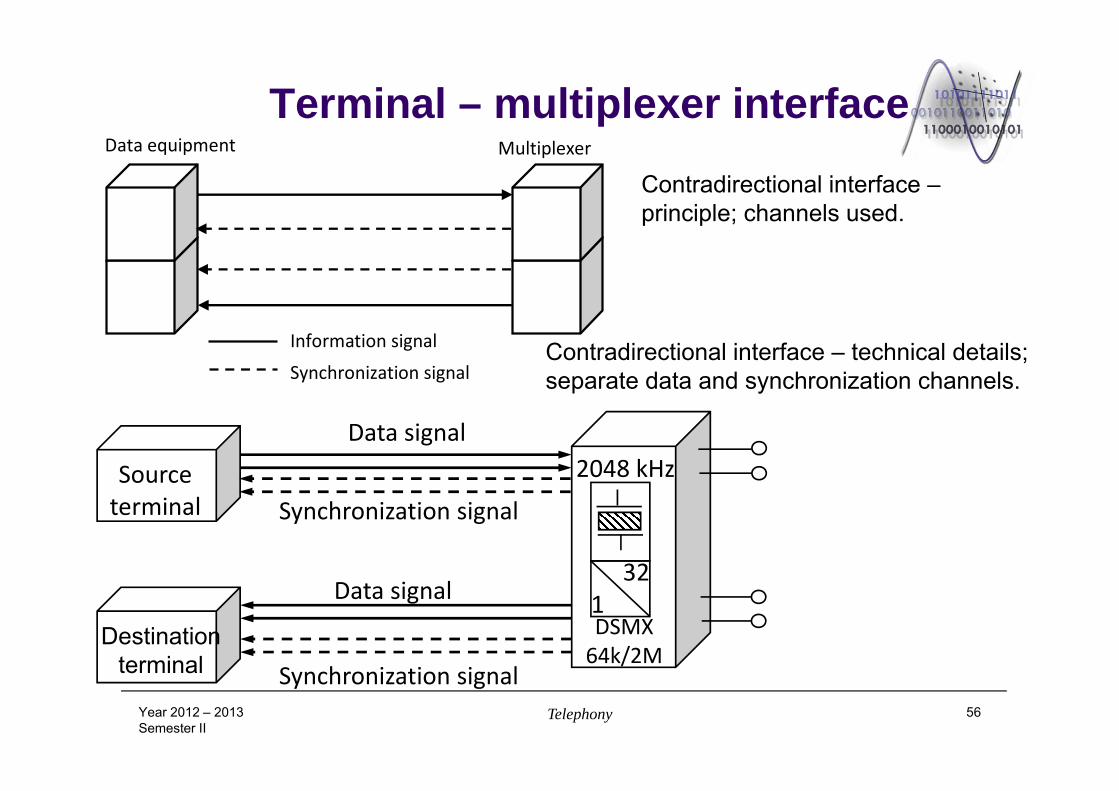
Contradirectional interface –principle; channels used.
321DSMX64k/2M
2048 kHzSource terminal
Destination terminal
Data signal
Data signal
Synchronization signal
Synchronization signal
Contradirectional interface – technical details; separate data and synchronization channels.
MultiplexerData equipment
Information signal
Synchronization signal
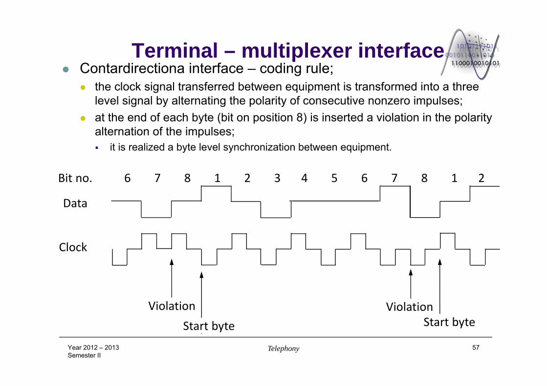
Terminal – multiplexer interface Contardirectiona interface – coding rule;
the clock signal transferred between equipment is transformed into a three level signal by alternating the polarity of consecutive nonzero impulses;
at the end of each byte (bit on position 8) is inserted a violation in the polarity alternation of the impulses; it is realized a byte level synchronization between equipment.
Year 2012 – 2013Semester II
Telephony 57
Clock
Data
Bit no.
Violation ViolationStart byte Start byte
6 7 8 1 2 3 4 5 6 7 8 1 2


![5334 Problems - Polgar [SOLUTIONS]](https://img.pdfslide.net/doc/110x75/563db98e550346aa9a9e7977/5334-problems-polgar-solutions.jpg)