Embed Size (px)
Citation preview

Curtiss-Wright Controls Defense Solutions
VPX3-685 Secure Routers Hardware Versions: VPX3-685-A13014-FC, VPX3-685-A13020-FC, VPX3-685-C23014-
FC, and VPX3-685-C23020-FC; Firmware Version: 2.0
FIPS 140-2 Non-Proprietary Security Policy
FIPS Security Level: 2
Document number: 828035
Document Version: 1.7
Prepared for: Prepared by:
Curtiss-Wright Controls Defense Solutions Corsec Security, Inc. 333 Palladium Drive
Kanata, Ontario 13135 Lee Jackson Memorial Highway, Suite 220
Fairfax, VA 22033 Canada K2V 1A6 United States of America
Phone: +1 (613) 599-9191 Phone: +1 (703) 267-6050
http://www.cwcdefense.com http://www.corsec.com

Security Policy, Version 1.7 February 12, 2014
Curtiss-Wright Controls Defense Solutions VPX3-685 Secure Routers
© 2014 Curtiss-Wright Controls Defense Solutions
This document may be freely reproduced and distributed whole and intact including this copyright notice.
Page 2 of 30
Table of Contents
1 INTRODUCTION ...................................................................................................................4
1.1 PURPOSE ................................................................................................................................................................4 1.2 REFERENCES ..........................................................................................................................................................4
1.3 DOCUMENT ORGANIZATION ............................................................................................................................4
2 VPX3-685 SECURE ROUTERS ..............................................................................................5
2.1 OVERVIEW.............................................................................................................................................................5
2.1.1 VPX3-685 Secure Routers ..................................................................................................................................5 2.1.2 VPX3-685 FIPS 140-2 Validation .....................................................................................................................7
2.2 MODULE SPECIFICATION.....................................................................................................................................8
2.3 MODULE INTERFACES ..........................................................................................................................................9 2.4 ROLES AND SERVICES .........................................................................................................................................11
2.4.1 Crypto Officer Role ............................................................................................................................................. 11
2.4.2 User Role................................................................................................................................................................ 11 2.4.3 Authentication Mechanism............................................................................................................................... 13
2.5 PHYSICAL SECURITY ...........................................................................................................................................14
2.6 OPERATIONAL ENVIRONMENT.........................................................................................................................15 2.7 CRYPTOGRAPHIC KEY MANAGEMENT ............................................................................................................15
2.8 EMI/EMC ............................................................................................................................................................21 2.9 SELF-TESTS ..........................................................................................................................................................21
2.9.1 Power–Up Self–Tests ......................................................................................................................................... 21
2.9.2 Conditional Self–Tests........................................................................................................................................ 21 2.9.3 User-Initiated Built-In-Tests .............................................................................................................................. 22
2.10 MITIGATION OF OTHER ATTACKS ..................................................................................................................22
3 SECURE OPERATION .........................................................................................................23
3.1 INITIAL SETUP......................................................................................................................................................23
3.1.1 VPX3-685 Installation ....................................................................................................................................... 23
3.1.2 VPX3-685 Tamper-Evident Seal Inspection ............................................................................................... 23 3.1.3 VPX3-685 FIPS-Approved mode Configuration......................................................................................... 24
3.2 CRYPTO OFFICER GUIDANCE ..........................................................................................................................24
3.2.1 Management ........................................................................................................................................................ 25 3.2.2 Zeroization ............................................................................................................................................................ 25
3.3 USER GUIDANCE ................................................................................................................................................25
4 ACRONYMS ..........................................................................................................................26
Table of Figures
FIGURE 1 – VPX3-685-A13014-FC AND VPX3-685-A13020-FC AIR-COOLED CHASSIS..........................................5
FIGURE 2 – VPX3-685-C23014-FC AND VPX3-685-C23020-FC CONDUCTION-COOLED CHASSIS .....................5
FIGURE 3 – TYPICAL DEPLOYMENT.........................................................................................................................................7 FIGURE 4 – BLOCK DIAGRAM WITH CRYPTOGRAPHIC BOUNDARY..................................................................................8
FIGURE 5 – FRONT (ABOVE) AND REAR VIEW ......................................................................................................................9
FIGURE 6 – VPX3-685 TAMPER EVIDENT SEAL PLACEMENT............................................................................................ 24
List of Tables
TABLE 1 – SECURITY LEVEL PER FIPS 140-2 SECTION .........................................................................................................7
TABLE 2 – VPX3-685 PORTS/INTERFACES ......................................................................................................................... 10
TABLE 3 – LOGICAL INTERFACE MAPPING.......................................................................................................................... 10 TABLE 4 – LED DESCRIPTIONS............................................................................................................................................. 11
TABLE 5 – MAPPING OF OPERATOR SERVICES TO INPUTS, OUTPUTS, CSPS, AND TYPE OF ACCESS......................... 12

Security Policy, Version 1.7 February 12, 2014
Curtiss-Wright Controls Defense Solutions VPX3-685 Secure Routers
© 2014 Curtiss-Wright Controls Defense Solutions
This document may be freely reproduced and distributed whole and intact including this copyright notice.
Page 3 of 30
TABLE 6 – AUTHENTICATION MECHANISM USED BY THE MODULES ............................................................................. 14
TABLE 7 – FIPS-APPROVED ALGORITHM IMPLEMENTATIONS IN HARDWARE ............................................................... 15
TABLE 8 – FIPS-APPROVED ALGORITHM IMPLEMENTATIONS IN FIRMWARE.................................................................. 16 TABLE 8A – NON-APPROVED AND NON-COMPLIANT ALGORITHM IMPLEMENTATIONS ........................................... 16
TABLE 9 – LIST OF CRYPTOGRAPHIC KEYS, CRYPTOGRAPHIC KEY COMPONENTS, AND CSPS................................. 18
TABLE 10 – ACRONYMS ........................................................................................................................................................ 26

Security Policy, Version 1.7 February 12, 2014
Curtiss-Wright Controls Defense Solutions VPX3-685 Secure Routers
© 2014 Curtiss-Wright Controls Defense Solutions
This document may be freely reproduced and distributed whole and intact including this copyright notice.
Page 4 of 30
1 Introduction
1.1 Purpose This is a non-proprietary Cryptographic Module Security Policy for the VPX3-685 Secure Routers from
Curtiss-Wright Controls Defense Solutions. This Security Policy describes how the VPX3-685 Secure
Routers meet the security requirements of Federal Information Processing Standards (FIPS) Publication
140-2, which details the U.S. and Canadian Government requirements for cryptographic modules. More
information about the FIPS 140-2 standard and validation program is available on the National Institute of
Standards and Technology (NIST) and the Communications Security Establishment Canada (CSEC)
Cryptographic Module Validation Program (CMVP) website at http://csrc.nist.gov/groups/STM/cmvp.
This document also describes how to run the modules in a secure FIPS-Approved mode of operation. This
policy was prepared as part of the Level 2 FIPS 140-2 validation of the modules. The VPX3-685 Secure
Routers are referred to in this document as the VPX3-685 modules, the cryptographic modules or the
modules.
1.2 References This document deals only with operations and capabilities of the modules in the technical terms of a FIPS
140-2 cryptographic module security policy. More information is available on the modules from the
following sources:
The Curtiss-Wright Controls Defense Solutions website (http://www.cwcdefense.com/) contains
information on the full line of products from Curtiss-Wright Controls Defense Solutions.
The CMVP website (http://csrc.nist.gov/groups/STM/cmvp/documents/140-1/140val-all.htm)
contains contact information for individuals to answer technical or sales-related questions for the
modules.
1.3 Document Organization The Security Policy document is one document in a FIPS 140-2 Submission Package. In addition to this
document, the Submission Package contains:
Vendor Evidence document
Finite State Model document
Other supporting documentation as additional references
This Security Policy and the other validation submission documentation were produced by Corsec Security,
Inc. under contract to Curtiss-Wright Controls Defense Solutions. With the exception of this Non-
Proprietary Security Policy, the FIPS 140-2 Submission Package is proprietary to Curtiss-Wright Controls
Defense Solutions and is releasable only under appropriate non-disclosure agreements. For access to these
documents, please contact Curtiss-Wright Controls Defense Solutions.

Security Policy, Version 1.7 February 12, 2014
Curtiss-Wright Controls Defense Solutions VPX3-685 Secure Routers
© 2014 Curtiss-Wright Controls Defense Solutions
This document may be freely reproduced and distributed whole and intact including this copyright notice.
Page 5 of 30
2 VPX3-685 Secure Routers
2.1 Overview Curtiss-Wright Controls Defense Solutions is a leading provider of state-of-the-art embedded computing
solutions that offer high-density data processing under rugged operating conditions. Their product and
service offerings include cutting-edge radar and graphics solutions, high-speed communication, custom
software design and hardware engineering, and manufacturing services. By providing flexible design
options and complete product integration services, Curtiss-Wright has earned itself a significant customer
base in the aerospace, defense, and commercial markets.
2.1.1 VPX3-685 Secure Routers
The VPX3-685 Secure Routers are high-performance air- or conduction-cooled, 3U OpenVPX network
security appliances delivering converged firewall, intrusion detection or prevention system, switching,
routing and Virtual Private Networking (VPN) services. Designed for secure rugged military or aerospace
networks (Ethernet-based networks in air, land, and sea vehicles), the VPX3-685 prevents unauthorized
access to critical information. It can be used to secure a data storage network or to protect mission-critical
applications from hostile attacks.
Figure 1 and Figure 2 below shows a picture of the VPX3-685 Secure Routers with air-cooled and
conduction-cooled chassis respectively.
Figure 1 – VPX3-685-A13014-FC and VPX3-685-A13020-FC Air-Cooled Chassis
Figure 2 – VPX3-685-C23014-FC and VPX3-685-C23020-FC Conduction-Cooled Chassis
The VPX3-685 can be used as an intelligent Layer 2-managed switch or an advanced Layer 3-managed
switch or router. It incorporates security software and a high-performance hardware-based security engine.
Using VPX3-685, systems integrators can make high performance chassis-to-chassis, board-to-board or

Security Policy, Version 1.7 February 12, 2014
Curtiss-Wright Controls Defense Solutions VPX3-685 Secure Routers
© 2014 Curtiss-Wright Controls Defense Solutions
This document may be freely reproduced and distributed whole and intact including this copyright notice.
Page 6 of 30
CPU1-to-CPU connections over Gigabit Ethernet. Advanced security and network features provided by the
modules include:
Support for VLANs2
and VPNs (IPsec3) to protect dedicated networks
Spanning Tree Algorithms (STP4, RSTP
5, MSTP
6), IP multicasting, intelligent routing (RIP
7,
OSPF8), Quality of Service (QoS), priority scheduling, network management, and remote
monitoring
Network Address Translation (NAT) routing for IPv4 masquerading
Port- and protocol-based Access Control Lists to prevent unauthorized access
IPv6 with IPsec tunneling for secure communications channels
Advanced standards-based cryptographic functions (encryption, decryption, and authentication)
The VPX3-685 modules implement Non-Volatile Memory Read Only (NVMRO) protection. NVMRO is a
hardware implementation that physically prevents writing to any non-volatile memory device on the
modules. By default, the NVMRO signal is asserted when entering FIPS-Approved mode.
2.1.1.1 VPX3-685 System
The validated VPX3-685 Secure Routers support twelve 10/100/1000 Base-T Ethernet ports. In addition,
the VPX3-685 Secure Routers will either have two 10 GbE ports or eight 1000 Base-KX ports. Embedded
backplane routing is supported with standard Base-T GbE and 10GbE (XAUI9) interfaces. The VPX3-685
Secure Routers covered in this Security Policy support the following slot profiles10
:
VPX3-685-A13014-FC and VPX3-685-C23014-FC
o Twelve 1000 Base-T ports + Two 10 GbE ports (SLT3-SWH-2F12T11
Slot Profile)
VPX3-685-A13020-FC and VPX3-685-C23020-FC
o Twelve 1000 Base-T ports + Eight 1000 Base-x (SerDes) ports (SLT3-SWH-8U12T Slot Profile)
The VPX3-685 Secure Routers are comprised of a motherboard enclosed in a secure tamper-evident
production-grade opaque metal case. The two primary devices on the board are the encryption-enabled
general-purpose processor and the switch fabric. The processor includes CAVP-validated hardware
implementations of cryptographic algorithms, referenced in Table 7. The switch fabric is used to support
network routing and switching. The VPX3-685 firmware architecture provides support for Ethernet
switching, routing and cryptographic functionality implemented in the firmware.
Management of the VPX3-685 Secure Routers is possible via CLI
12 or WebNM
13. The system provides
secure management interfaces through secure HTTP14
(HTTPS15
) and Secure Shell (SSH). Figure 3 below
illustrates a typical deployment scenario of the VPX3-685 Secure Routers. The cryptographic boundary is
shown by the red-colored dotted line and includes the entire steel chassis of the VPX3-685 Secure Routers.
1 CPU – Central Processing Unit 2 VLAN – Virtual Local Area Network 3 IPsec – Internet Protocol Security 4 STP – Spanning Tree Protocol 5 RSTP – Rapid Spanning Tree Protocol 6 MSTP – Multiple Spanning Tree Protocol 7 RIP – Routing Information Protocol 8 OSPF – Open Shortest Path First 9 XAUI – X (ten) Attachment Unit Interface 10 Slot profile – the Open VPX profile with basic definitions of planes (type, number and size) and user-defined pins 11 SLT3-SWH-2F12T – A 3U Open VPX compliant Switch type Slot profile with 2 Fat and 12 Thin pipes 12 CLI – Command Line Interface 13 WebNM – Web-based Network Management 14 HTTP – Hyper Text Transfer Protocol 15 HTTPS – HTTP over SSL

Security Policy, Version 1.7 February 12, 2014
Curtiss-Wright Controls Defense Solutions VPX3-685 Secure Routers
© 2014 Curtiss-Wright Controls Defense Solutions
This document may be freely reproduced and distributed whole and intact including this copyright notice.
Page 7 of 30
Figure 3 – Typical Deployment
2.1.2 VPX3-685 FIPS 140-2 Validation
The VPX3-685 Secure Routers are validated at the FIPS 140-2 Section levels as shown in Table 1 below:
Table 1 – Security Level Per FIPS 140-2 Section
Section Section Title Level
1 Cryptographic Module Specification 3
2 Cryptographic Module Ports and Interfaces 2
3 Roles, Services, and Authentication 3
4 Finite State Model 2
5 Physical Security 2
6 Operational Environment N/A16
7 Cryptographic Key Management 2
8 EMI/EMC17 2
9 Self-tests 2
10 Design Assurance 3
11 Mitigation of Other Attacks N/A
16 N/A – Not applicable 17 EMI/EMC – Electromagnetic Interference / Electromagnetic Compatibility

Security Policy, Version 1.7 February 12, 2014
Curtiss-Wright Controls Defense Solutions VPX3-685 Secure Routers
© 2014 Curtiss-Wright Controls Defense Solutions
This document may be freely reproduced and distributed whole and intact including this copyright notice.
Page 8 of 30
Flash
256Mx16
Flash
256Mx16
UART
XFMR
XFMR
XFMR
XFMR
JT
AG
CP
U C
OM
IPM
B x
2
IPM
I C
OM
R
S23
2
FR
U
T
EM
P
XE
[0:1
]
XA
UI
2.2 Module Specification The VPX3-685 Secure Routers are multi-chip embedded cryptographic modules including firmware and hardware. The main hardware components consist of a main processor, memory, and switch fabric with a
backplane interface providing 10/100/1000 Base-T interfaces, 10 GbE interfaces and IPMI18
. The entire VPX3-685 board (including the enclosure) is defined as the cryptographic boundary of the modules. Figure 4 shows a block diagram for the modules and the red-colored dotted line indicates the cryptographic boundary. Power is supplied to the modules from the VPX power rails and may be reconfigured for +5v or
+3.3v source power.
FIPS 140-2
Cryptographic
Boundary
SDRAM Flash
XFMR
PHY
RS232
10/100
Ethernet
UART
Memory
Control
Local Bus
Control
Processor
I2C
NvRAM
RTC,
TEMP
UART Switch Fabric
Interface
Crypto Engine
IPMI
Switch Fabric
Interface
Switch Fabric
SGMII /SerDes
[0:7] [8:11]
SerDes
[12:19]
PHY PHY
Configuration Note:
SLT3-SWH-2F12T
SLT3-SWH-1F4U12T
SLT3-SWH-8U12T
XFMR
XFMR
VPX P0
VPX P1/P2
Figure 4 – Block Diagram with Cryptographic Boundary19
18 IPMI – Intelligent Platform Management Interface 19 SDRAM – Synchronous Dynamic Random Access Memory
XMFR – Transformer
PHY – Physical Layer
I2C – Inter-Integrated Circuit
NVRAM – Non-Volatile Random Access Memory
Security Policy, Version 1.7 February 12, 2014
Curtiss-Wright Controls Defense Solutions VPX3-685 Secure Routers
© 2014 Curtiss-Wright Controls Defense Solutions
This document may be freely reproduced and distributed whole and intact including this copyright notice.
Page 9 of 30
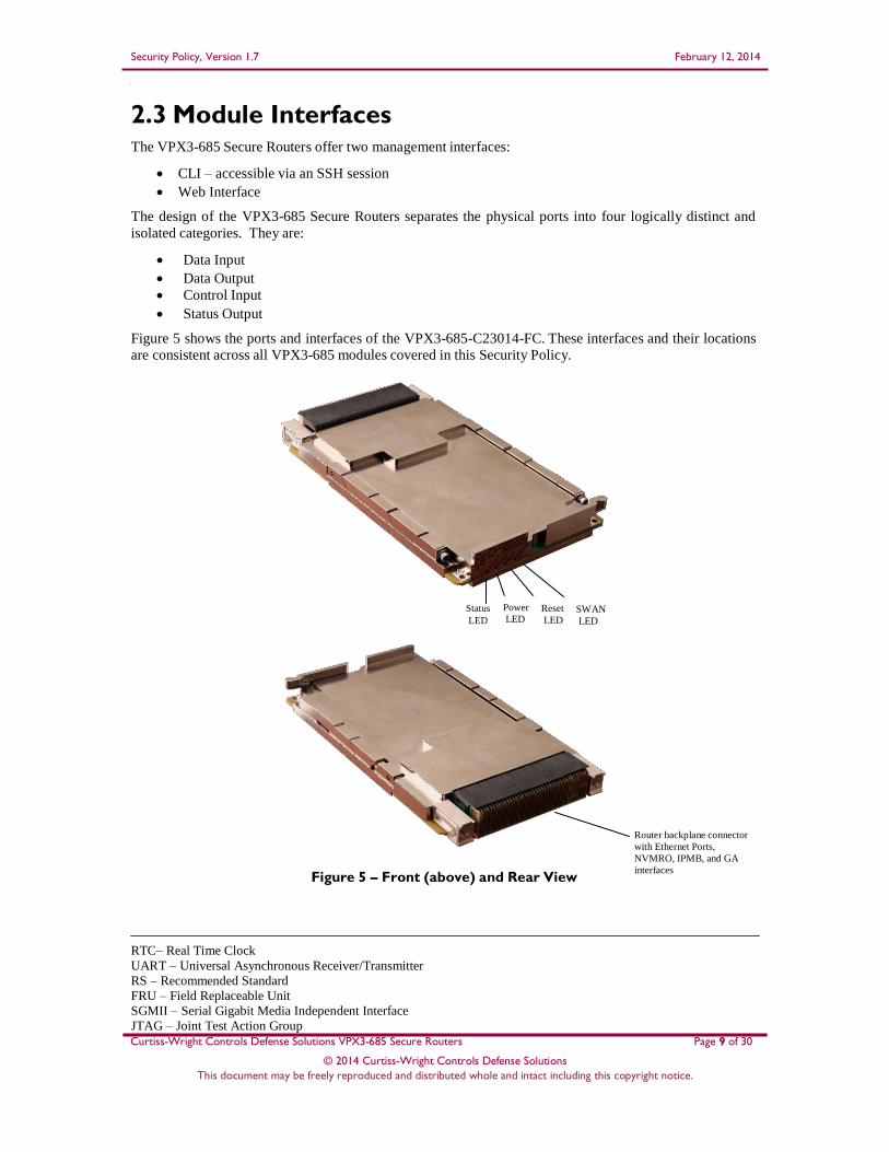
2.3 Module Interfaces The VPX3-685 Secure Routers offer two management interfaces:
CLI – accessible via an SSH session
Web Interface
The design of the VPX3-685 Secure Routers separates the physical ports into four logically distinct and
isolated categories. They are:
Data Input
Data Output
Control Input
Status Output
Figure 5 shows the ports and interfaces of the VPX3-685-C23014-FC. These interfaces and their locations
are consistent across all VPX3-685 modules covered in this Security Policy.
Status
LED
Power
LED Reset
LED SWAN
LED
Figure 5 – Front (above) and Rear View
Router backplane connector
with Ethernet Ports,
NVMRO, IPMB, and GA
interfaces
RTC– Real Time Clock
UART – Universal Asynchronous Receiver/Transmitter
RS – Recommended Standard
FRU – Field Replaceable Unit
SGMII – Serial Gigabit Media Independent Interface
JTAG – Joint Test Action Group

Security Policy, Version 1.7 February 12, 2014
Curtiss-Wright Controls Defense Solutions VPX3-685 Secure Routers
© 2014 Curtiss-Wright Controls Defense Solutions
This document may be freely reproduced and distributed whole and intact including this copyright notice.
Page 10 of 30
The VPX3-685 modules are OpenVPX modules complying to the SLT3-SWH-2F12T or SLT3-SWH-
8U12T configuration with the ports/interfaces listed in Table 2 below. The VPX3-685-A13014 and VPX3-
685-C23014 modules support the SLT3-SWH-2F12T slot profile. The VPX3-685-A13020 and VPX3-685-
C23020 modules support the SLT3-SWH-8U12T slot profile. Ports available on one slot profile, and not on
the other, will be explicitly stated in Table 2 below.
Table 2 – VPX3-685 Ports/Interfaces
Port/Interface Description
TP01 – TP12 12 x 10/100/1000Base-T Ethernet ports
DP01 – DP02 2 x 10 GigE Ethernet Ports (SLT3-SWH-2F12T slot profile)
SGP01 – SGP08 8x 1GbE SerDes Ports (SLT3-SWH-8U12T slot profile)
*OOB Out Of Band (OOB) download port, 10/100 Base-T Ethernet
Interface
*RS232 Serial console interface
IPMB Intelligent Platform Management Bus
*ALT_BOOT Alternative Boot selection interface
NVMRO Non-Volatile Memory Read-only control interface
Reset Reset interface (SYS_RST or Mskble RST)
GA Geographical Address interface
LEDs20 Light Emitting Diodes indicating various status of VPX3-685
Power Power interface (VS1, VS2, VS3, AUX and VBAT)
To prevent tampering of programmable parts, JTAG access is physically disabled at the factory. The
modules also disable the IPMI COM, RS-232 and Out-Of-Band Ethernet interfaces when FIPS-Approved
mode is set. The Field Replaceable Unit (FRU) is a mass memory device attached to the IPMI controller.
It is factory programmable and write-protected through a controlled process when it leaves the factory.
The ports and interfaces marked with an asterisk (*) in Table 2 are physically disabled in the FIPS-
Approved mode of operation. Table 3 lists the physical ports/interfaces available in the VPX3-685
modules, and also provides the mapping from the physical ports/interfaces to logical interfaces as defined
by FIPS 140-2.
Table 3 – Logical Interface Mapping
FIPS 140-2 Logical Interface Physical Port/Interface
Data Input Interface Gigabit Ethernet ports, Geographical
Address interface
Data Output Interface Gigabit Ethernet ports
Control Input Interface Gigabit Ethernet ports, IPMB interface, NVMRO, Reset
Status Output Interface LEDs, Gigabit Ethernet ports, IPMB interface
Power Input Power interface
20 LED – Light Emitting Diode

Security Policy, Version 1.7 February 12, 2014
Curtiss-Wright Controls Defense Solutions VPX3-685 Secure Routers
© 2014 Curtiss-Wright Controls Defense Solutions
This document may be freely reproduced and distributed whole and intact including this copyright notice.
Page 11 of 30
As shown in Figure 5, the VPX3-685 Secure Routers have a number of LEDs that indicate the state of the
modules. The descriptions for the LEDs are listed in Table 4.
Table 4 – LED Descriptions
LED Color State Description
STAT Red On Power-up Built-In-Test (PBIT), Initiated Built-In-Test
(IBIT), or Continuous Built-In-Test (CBIT) has failed
Green On Built-In-Test (BIT) has passed
PWR Green On The VPX3-685 has power and all on-board power
supplies are operating
RST Red On The VPX3-685 is in reset state
SWAN
(FIPS-Approved mode)
Blue On The VPX3-685 is in FIPS-Approved mode
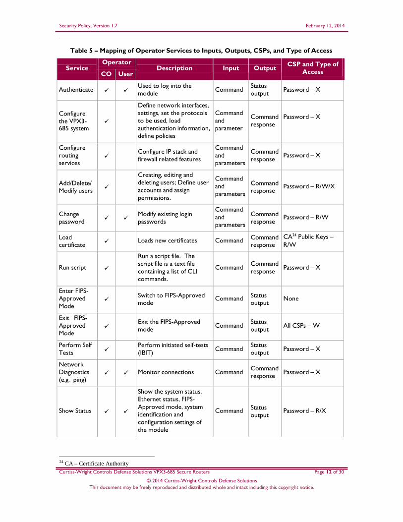
2.4 Roles and Services As required by FIPS 140-2, the modules support two roles that operators may assume: a Crypto Officer
(CO) role and a User role. Multiple concurrent operators are able to access the module at the same time.
The VPX3-685 Secure Routers offer privilege levels 1-15 that provide operators with different levels of
access to the modules as defined by the CO who performs initial configuration. The keys and Critical
Security Parameters (CSPs) listed in the Table 5 indicate the type of access required using the following
notation:
R – Read: The CSP is read.
W – Write: The CSP is established, generated, modified, or zeroized.
X – Execute: The CSP is used within an Approved or Allowed security function or authentication
mechanism.
2.4.1 Crypto Officer Role
The CO is the administrator of the modules. Only a Crypto Officer can create other COs (privilege level 1-
15) and Users (privilege levels 1-4) and provision the VPX3-685 to operate in FIPS-Approved mode. The
Crypto Officers have access to the modules’ services and one or more CSPs. CO services are provided via
the supported secure protocols, including Transport Layer Security (TLS), SSH, and IPsec21
or IKE22
for
VPN23
connections. Descriptions of the services available to the Crypto Officer are provided in Table 5.
2.4.2 User Role
The User (privilege levels 1-4) is limited to information and status activities and cannot configure the
devices. Table 5 below lists the services available to the User.
21 IPsec – Internet Protocol Security 22 IKE – Internet Key Exchange 23 VPN – Virtual Private Network
Security Policy, Version 1.7 February 12, 2014
Curtiss-Wright Controls Defense Solutions VPX3-685 Secure Routers
© 2014 Curtiss-Wright Controls Defense Solutions
This document may be freely reproduced and distributed whole and intact including this copyright notice.
Page 12 of 30
Table 5 – Mapping of Operator Services to Inputs, Outputs, CSPs, and Type of Access
Service
Operator Description
Input
Output
CSP and Type of
Access CO User
Authenticate
Used to log into the
module
Command
Status
output
Password – X
Configure
the VPX3- 685 system
Define network interfaces,
settings, set the protocols
to be used, load
authentication information,
define policies
Command
and
parameter
Command
response
Password – X
Configure
routing
services
Configure IP stack and
firewall related features
Command
and
parameters
Command
response
Password – X
Add/Delete/ Modify users
Creating, editing and
deleting users; Define user
accounts and assign
permissions.
Command
and
parameters
Command response
Password – R/W/X
Change
password
Modify existing login
passwords
Command
and
parameters
Command
response
Password – R/W
Load certificate
Loads new certificates
Command Command response
CA24 Public Keys –
R/W
Run script
Run a script file. The
script file is a text file
containing a list of CLI
commands.
Command
Command
response
Password – X
Enter FIPS-
Approved
Mode
Switch to FIPS-Approved mode
Command
Status output
None
Exit FIPS-
Approved
Mode
Exit the FIPS-Approved
mode
Command
Status
output
All CSPs – W
Perform Self
Tests
Perform initiated self-tests
(IBIT)
Command Status
output
Password – X
Network
Diagnostics
(e.g. ping)
Monitor connections
Command
Command
response
Password – X
Show Status
Show the system status,
Ethernet status, FIPS-
Approved mode, system
identification and
configuration settings of
the module
Command
Status
output
Password – R/X
24 CA – Certificate Authority

Security Policy, Version 1.7 February 12, 2014
Curtiss-Wright Controls Defense Solutions VPX3-685 Secure Routers
© 2014 Curtiss-Wright Controls Defense Solutions
This document may be freely reproduced and distributed whole and intact including this copyright notice.
Page 13 of 30
Service Operator
Description
Input
Output CSP and Type of
Access CO User
System Log
View system status messages
Command
Status output
Password – X
Zeroize
Zeroize all keys and CSPs.
Command Command
response
All CSPs – W
Reset
Reset the module
Command
Status
output
CSPs stored in
RAM25 – W
RADIUS26 or
TACACS27
service
RADIUS or TACACS
server logs in and
performs authentication.
Command
Command
response
RADIUS or TACACS
Shared Secret Key –
X
TLS
Login to the module via
Web interface and
perform any of the
services listed above
Command
Command
response/
Status
output
Password – X
TLS Public key – R/X
TLS Private key – X
TLS Session key –
R/W/X
TLS Authentication Key – R/W/X
SSH
Login to the module
remotely using SSH
protocol and perform any
of the services listed above
Command
Command
response/
Status
output
Password – R
SSH Authentication
Key – R/W/X SSH Encryption Key
– R/W/X
IPsec/IKE
Login to the module over
VPN and perform any of
the services listed above
Command
Command
response/
Status
output
Password – R
IKE pre-shared Key – R/W/X
IKE Private Key –
R/W/X
IKE DH28 key-pairs – R/W/X IPsec Message
Authentication Key –
R/W/X
IPsec Message
Encryption Key –
R/W/X
IPsec ESP29 Key – R/W/X
2.4.3 Authentication Mechanism
All services provided by the modules require the operator to assume a role and a specific identity. The
modules provide services only to authenticated operators. The modules perform identity-based
authentication.
25 RAM – Random Access Memory 26 RADIUS – Remote Authentication Dial-In User Service 27 TACACS – Terminal Access Controller Access-Control System 28 DH – Diffie Hellman 29 ESP – Encapsulating Security Payload

Security Policy, Version 1.7 February 12, 2014
Curtiss-Wright Controls Defense Solutions VPX3-685 Secure Routers
© 2014 Curtiss-Wright Controls Defense Solutions
This document may be freely reproduced and distributed whole and intact including this copyright notice.
Page 14 of 30
All users authenticate to the modules using a username and password or by the use of public key
certificates. All users are required to follow the complex password restrictions. Table 6 lists the
authentication mechanisms used by the modules.
Table 6 – Authentication Mechanism Used by the Modules
Authentication
Type
Strength
Username/Password The minimum length of the password is eight characters, with 95 different case-
sensitive alphanumeric characters and symbols possible for usage. The “!” is
only supported as the last character of the password.
The chance of a random attempt falsely succeeding is 1: (947 x 95), or 1: 6,160,537,144,830,080.
The fastest network connection supported by the modules is 10 Gbps.
Hence at most (10 ×109 × 60 = 6 × 1011 =) 600,000,000,000 bits of data can be transmitted in one minute. Therefore, the probability that a random attempt
will succeed or a false acceptance will occur in one minute is 1 : [(947 x 95) possible passwords / ((6 ×1011 bits per minute) / 64 bits per password)]
1: (947 x 95) possible passwords / 9,375,000,000 passwords per minute) 1: 657,123;
which is less than 1:100,000 as required by FIPS 140-2.
Public Key
Certificates
The modules support RSA30 digital certificate authentication of users during
IPsec/IKE. Using conservative estimates and equating a 2048-bit
RSA key to a 112 bit symmetric key, the probability for a random attempt to
succeed is 1:2112 or 1: 5.19 x 1033.
The fastest network connection supported by the modules is 100 Mbps.
Hence at most (100 ×106 × 60 = 6 × 109 =) 6,000,000,000 bits of data can be transmitted in one minute. Therefore, the probability that a random attempt
will succeed or a false acceptance will occur in one minute is
1: (2112 possible keys / ((6 × 109 bits per minute) / 112 bits per key))
1: (2112 possible keys / 53,571,428 keys per minute)
1: 96.92 × 1024; which is less than 100,000 as required by FIPS 140-2.
2.5 Physical Security All CSPs are stored and protected within the production-grade enclosures of the VPX3-685 Secure Routers. The removable enclosures are opaque within the visible spectrum and are protected by a tamper-evident
seal. The structure of the enclosures is such that the top half is screwed in from the PWB31
side and the bottom half screws go through the PWB and screw into the top half of the enclosures. The tamper evident seal is placed over one screw on the bottom half. The metal is such that any attempts to access without removing the covered screw would result in evidence in the metal cover itself. While the modules are running in the FIPS-Approved mode, the tamper protection controller within the modules monitors the
power signal and zeroizes all keys and CSPs on detection of a tamper event32
. All of the components within the modules are production grade. The placement of tamper-evident seals can be found in Section
3.1 of this document.
30 RSA – Rivest, Shamir, Adleman 31 PWB – Printed Wiring Board 32 A tamper event is defined as removing the module from a supported chassis which results in the loss of power

Security Policy, Version 1.7 February 12, 2014
Curtiss-Wright Controls Defense Solutions VPX3-685 Secure Routers
© 2014 Curtiss-Wright Controls Defense Solutions
This document may be freely reproduced and distributed whole and intact including this copyright notice.
Page 15 of 30
2.6 Operational Environment The operational environment requirements do not apply to the VPX3-685 Secure Routers, because the
modules do not provide a general-purpose operating system (OS) to the user. The operating system is not
modifiable by the operator and only the modules’ signed image can be executed.
2.7 Cryptographic Key Management The VPX3-685 modules use the FIPS-validated algorithm implementations in Hardware as listed in Table 7
below.
Table 7 – FIPS-Approved Algorithm Implementations in Hardware
Algorithm
Certificate Number
Advanced Encryption Standard (AES) in CBC33, ECB34,
CFB12835, CTR36 and CMAC37 modes (128-bit and 256-bit keys)
963
Triple Data Encryption Standard (Triple-DES) – CBC, ECB,
OFB ; 3-key
758
Secure Hash Algorithm (SHA)-1, SHA-224, SHA-256, SHA-
384, and SHA-512
934
Keyed-Hash Message Authentication Code (HMAC) using
SHA-1*, SHA-224, SHA-256, SHA-384, and SHA-512
538
*Note: The use of SHA-1 for the purpose of Digital Signature Generation is non-compliant. The use of
SHA-1 for the purpose of Digital Signature Verification is allowed for legacy-use. Any other use of SHA-
1 for non-digital signature generation applications is acceptable and approved.
Additionally, the VPX3-685 modules support FIPS-Approved algorithms implemented in firmware as
listed in Table 8.
33 CBC – Cipher Block Chaining 34 ECB – Electronic Codebook 35 CFB128 – Cipher Feedback (128-bit) 36 CTR – Counter Mode 37 CMAC – CBC Message Authentication Code
Security Policy, Version 1.7 February 12, 2014
Curtiss-Wright Controls Defense Solutions VPX3-685 Secure Routers
© 2014 Curtiss-Wright Controls Defense Solutions
This document may be freely reproduced and distributed whole and intact including this copyright notice.
Page 16 of 30
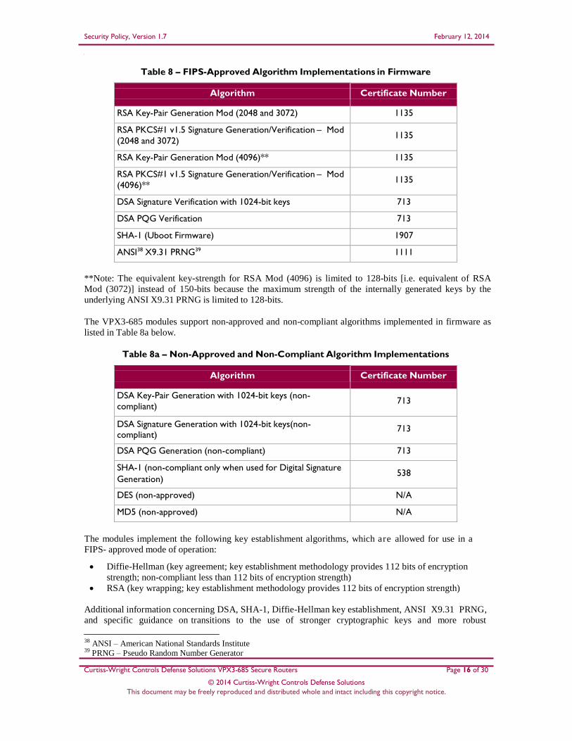
Table 8 – FIPS-Approved Algorithm Implementations in Firmware
Algorithm
Certificate Number
RSA Key-Pair Generation Mod (2048 and 3072) 1135
RSA PKCS#1 v1.5 Signature Generation/Verification – Mod
(2048 and 3072)
1135
RSA Key-Pair Generation Mod (4096)** 1135
RSA PKCS#1 v1.5 Signature Generation/Verification – Mod
(4096)**
1135
DSA Signature Verification with 1024-bit keys 713
DSA PQG Verification 713
SHA-1 (Uboot Firmware) 1907
ANSI38 X9.31 PRNG39 1111
**Note: The equivalent key-strength for RSA Mod (4096) is limited to 128-bits [i.e. equivalent of RSA
Mod (3072)] instead of 150-bits because the maximum strength of the internally generated keys by the
underlying ANSI X9.31 PRNG is limited to 128-bits.
The VPX3-685 modules support non-approved and non-compliant algorithms implemented in firmware as
listed in Table 8a below.
Table 8a – Non-Approved and Non-Compliant Algorithm Implementations
Algorithm
Certificate Number
DSA Key-Pair Generation with 1024-bit keys (non-
compliant)
713
DSA Signature Generation with 1024-bit keys(non- compliant)
713
DSA PQG Generation (non-compliant) 713
SHA-1 (non-compliant only when used for Digital Signature
Generation)
538
DES (non-approved) N/A
MD5 (non-approved) N/A
The modules implement the following key establishment algorithms, which are allowed for use in a
FIPS- approved mode of operation:
Diffie-Hellman (key agreement; key establishment methodology provides 112 bits of encryption
strength; non-compliant less than 112 bits of encryption strength)
RSA (key wrapping; key establishment methodology provides 112 bits of encryption strength)
Additional information concerning DSA, SHA-1, Diffie-Hellman key establishment, ANSI X9.31 PRNG,
and specific guidance on transitions to the use of stronger cryptographic keys and more robust
38 ANSI – American National Standards Institute 39 PRNG – Pseudo Random Number Generator

Security Policy, Version 1.7 February 12, 2014
Curtiss-Wright Controls Defense Solutions VPX3-685 Secure Routers
© 2014 Curtiss-Wright Controls Defense Solutions
This document may be freely reproduced and distributed whole and intact including this copyright notice.
Page 17 of 30
algorithms is contained in NIST Special Publication 800-131A. The modules support the CSPs
described in Table 9.

Security Policy, Version 1.7 February 12, 2014
40 SECRAM - SecureRAM
Curtiss-Wright Controls Defense Solutions VPX3-685 Secure Routers
© 2014 Curtiss-Wright Controls Defense Solutions
This document may be freely reproduced and distributed whole and intact including this copyright notice.
Page 18 of 30
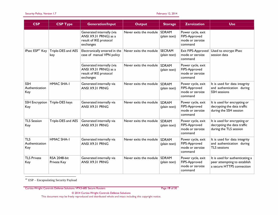
Table 9 – List of Cryptographic Keys, Cryptographic Key Components, and CSPs
CSP
CSP Type
Generation/Input
Output
Storage
Zeroization
Use
IKE pre-shared key
Alpha-numeric
string (Shared
Secret)
Electronically entered by the Crypto Officer
Never exits the module SECRAM40
(plain text)
Exit FIPS-Approved
mode or zeroize
command
Used for authentication
during IKE when the
authentication method is
selected as “preshared”
IKE Private Key RSA 2048-bit
Private key
Generated externally;
Input encrypted via SFTP
Never exits the module SECRAM
(plain text)
Power cycle, exit
FIPS-Approved
mode or zeroize
command
Used for authentication
during IKE when the
authentication method is
selected as “cert”
IKE Public Key RSA 2048-bit Public
key
Generated Internally via
ANSI X9.31 PRNG
Exits the module in
plaintext in the form of
a certificate
SECRAM
(plain text)
Power cycle, exit
FIPS-Approved
mode or zeroize
command
Used for peer authentication
to module during IKE when
the authentication method is
selected as “cert”
IKE DH
Symmetric Key
2048-bit DH session
key
Generated internally during
IKE negotiation via ANSI
X9.31 PRNG
Never exits the module SDRAM
(plain text)
Power cycle, exit
FIPS-Approved
mode or zeroize
command
Exchanging shared secret to
derive encryption keys
during IKE
IPsec Message
Authentication
Key
HMAC SHA-1 for
IPsec data integrity
Electronically entered in the
case of manual VPN policy
Never exits the module SECRAM
(plain text)
Exit FIPS-Approved
mode or zeroize
command
Used for peer authentication
before encrypting IPsec
packets
Generated internally via
ANSI X9.31 PRNG) as a
result of IKE protocol
exchanges
Never exits the module SDRAM
(plain text)
Power cycle, exit
FIPS-Approved
mode or zeroize
command
IPsec Message
Encryption Key
Triple-DES and AES
key
Electronically entered in the
case of manual VPN policy
Never exits the module SDRAM
(plain text)
Power cycle, exit
FIPS-Approved
mode or zeroize
command
Used to encrypt peer-to-
peer IPsec messages
Security Policy, Version 1.7 February 12, 2014
Curtiss-Wright Controls Defense Solutions VPX3-685 Secure Routers
© 2014 Curtiss-Wright Controls Defense Solutions
This document may be freely reproduced and distributed whole and intact including this copyright notice.
Page 19 of 30
CSP
CSP Type
Generation/Input
Output
Storage
Zeroization
Use
Generated internally (via
ANSI X9.31 PRNG) as a
result of IKE protocol
exchanges
Never exits the module SDRAM
(plain text)
Power cycle, exit
FIPS-Approved
mode or zeroize
command
IPsec ESP41 Key Triple-DES and AES
key
Electronically entered in the
case of manual VPN policy
Never exits the module SECRAM
(plain text)
Exit FIPS-Approved
mode or zeroize
command
Used to encrypt IPsec
session data
Generated internally (via
ANSI X9.31 PRNG) as a
result of IKE protocol
exchanges
Never exits the module SDRAM
(plain text)
Power cycle, exit
FIPS-Approved
mode or zeroize
command
SSH
Authentication
Key
HMAC SHA-1 Generated internally via
ANSI X9.31 PRNG
Never exits the module SDRAM
(plain text)
Power cycle, exit
FIPS-Approved
mode or zeroize
command
It is used for data integrity
and authentication during
SSH sessions
SSH Encryption
Key
Triple-DES keys Generated internally via
ANSI X9.31 PRNG
Never exits the module SDRAM
(plain text)
Power cycle, exit
FIPS-Approved
mode or zeroize
command
It is used for encrypting or
decrypting the data traffic
during the SSH session
TLS Session
Key
Triple-DES and AES Generated internally via
ANSI X9.31 PRNG
Never exits the module SDRAM
(plain text)
Power cycle, exit
FIPS-Approved
mode or zeroize
command
It is used for encrypting or
decrypting the data traffic
during the TLS session
TLS
Authentication
Key
HMAC SHA-1 Generated internally via
ANSI X9.31 PRNG
Never exits the module SDRAM
(plain text)
Power cycle, exit
FIPS-Approved
mode or zeroize
command
It is used for data integrity
and authentication during
TLS sessions
TLS Private
Key
RSA 2048-bit
Private Key
Generated internally via
ANSI X9.31 PRNG
Never exits the module SDRAM
(plain text)
Power cycle, exit
FIPS-Approved
mode or zeroize
command
It is used for authenticating a
peer attempting to establish
a secure HTTPS connection
41 ESP – Encapsulating Security Payload

Security Policy, Version 1.7 February 12, 2014
Curtiss-Wright Controls Defense Solutions VPX3-685 Secure Routers
© 2014 Curtiss-Wright Controls Defense Solutions
This document may be freely reproduced and distributed whole and intact including this copyright notice.
Page 20 of 30
CSP
CSP Type
Generation/Input
Output
Storage
Zeroization
Use
TLS Public Key RSA 2048-bit Public
Key
Generated internally via
ANSI X9.31 PRNG
Exits the module in
plaintext in the form of
a certificate
SDRAM
(plain text)
Power cycle, exit
FIPS-Approved
mode or zeroize
command
It is used by a peer
attempting to establish a
secure HTTPS connection
with the module
RADIUS
Shared Secret
Key
Alpha-numeric
string (Shared
Secret)
Electronically entered by
Crypto Officer
Never exits the module SECRAM
(plain text)
Exit FIPS-Approved
mode or zeroize
command
Used for authenticating the
RADIUS server to the VPX3-
685
Password Crypto Officer and
User passwords
Electronically entered by
Crypto Officer
Never exits the module SECRAM (plain text)
Exit FIPS-Approved
mode or zeroize
command
Used for authenticating the
Crypto Officer or User
ANSI X9.31
PRNG Seed
HMAC SHA-256 Generated internally Never exits the module SDRAM
(plain text)
Power cycle, exit
FIPS-Approved
mode or zeroize
command
Used to generate FIPS
approved random number
ANSI X9.31
PRNG Seed
Key
HMAC SHA-256 Generated internally Never exits the module SDRAM
(plain text)
Power cycle, exit
FIPS-Approved
mode or zeroize
command
Used to generate FIPS
approved random number
Caveat: The module generates cryptographic keys whose strengths are modified by available entropy, and thus the maximum encryption strength of the internally
generated module keys is 128 bits.

Security Policy, Version 1.7 February 12, 2014
Curtiss-Wright Controls Defense Solutions VPX3-685 Secure Routers
© 2014 Curtiss-Wright Controls Defense Solutions
This document may be freely reproduced and distributed whole and intact including this copyright notice.
Page 21 of 30
2.8 EMI/EMC The modules were tested and found to be conformant to the EMI/EMC requirements specified by 47 Code
of Federal Regulations, Part 15, Subpart B, Unintentional Radiators, Digital Devices, Class A (i.e., for
business use).
2.9 Self-Tests The VPX3-685 Secure Routers provide cryptographic support in the form of hardware and software
cryptographic algorithm implementations. As such, cryptographic self-tests are required to be performed
on these implementation in order to operate in a FIPS-Approved mode of operation.
2.9.1 Power–Up Self–Tests
The VPX3-685 Secure Routers implement the following Power-Up Self-Tests, also referred as Power-up
Built-In-Tests (PBIT):
Boot ROM42
firmware integrity self-test via 160-bit EDC
Power-up Self-Tests
o AES KAT43
o Triple-DES KAT
o SHA-1 KAT
o SHA-244
KAT
o HMAC SHA-1 KAT
o HMAC SHA-2 KAT
o RSA KAT
o DSA PCT45
o ANSI X9.31 PRNG KAT
Upon failing a PBIT KAT, the module will transition to a temporary error state, turning the STAT LED to
red. In the error state, the module will notify the operator of a failed PBIT, clear the error conditions, and
then exit the FIPS_Approved mode of operation. The SWAN LED will not illuminate and the module will
not be operating in the FIPS-Approved mode. To attempt the PBIT again and run the module in a FIPS-
Approved mode of operation, the operator will be required to restart the module.
2.9.2 Conditional Self–Tests
The VPX3-685 modules implement the following Conditional Built-In-Tests (CBIT) on the software
cryptographic algorithm implementations. CBITs are not required for the hardware algorithm
implementations.
Continuous Random Number Generator Test for the ANSI X9.31 PRNG
RSA PCT
DSA PCT
Upon failing a CBIT, the STAT LED will turn to red and the module will transition to a temporary error
state and display an error message to the operator when the syslog is configured46
. The error state will then
42 ROM – Read Only Memory 43 KAT – Known Answer Test 44 The SHA-2 hash family includes SHA-224, SHA-256, SHA-384, and SHA-512 45 PCT – Pairwise Consistency Test 46 Please refer to “VPX3-685 Command Line Interface (CLI) Software Reference Manual”

Security Policy, Version 1.7 February 12, 2014
Curtiss-Wright Controls Defense Solutions VPX3-685 Secure Routers
© 2014 Curtiss-Wright Controls Defense Solutions
This document may be freely reproduced and distributed whole and intact including this copyright notice.
Page 22 of 30
be cleared by the VPX3-685 and the module will restart outside the FIPS-Approved mode of operation. In
this mode the STAT LED stays red.
2.9.3 User-Initiated Built-In-Tests
The VPX3-685 modules implement the following Initiated Built-In-Tests (IBIT) that can be initiated by an
authorized operator. The operator will invoke the IBIT test through a single command via the CLI. IBITs
will only be performed on the firmware cryptographic algorithms:
SHA-1 KAT
SHA-256 KAT
SHA-512 KAT
HMAC SHA-1 KAT
HMAC SHA-2 KAT
Triple-DES KAT
AES KAT
RSA KAT
DSA PCT
ANSI X9.31 PRNG KAT
Upon failing an IBIT, the test will immediately stop, the STAT LED will turn to red and the module will
transition to a temporary error state. All data output from the module is suppressed. The error state will be
cleared by the VPX3-685 while all cryptographic operations are suspended. The CO at this point may
choose to retry the test or restart the module.
To perform on-demand self-tests on the hardware cryptographic algorithms, the module must be restarted.
2.10 Mitigation of Other Attacks This section is not applicable. The modules do not claim to mitigate any attacks beyond the FIPS 140-2
requirements for this validation.

Security Policy, Version 1.7 February 12, 2014
Curtiss-Wright Controls Defense Solutions VPX3-685 Secure Routers
© 2014 Curtiss-Wright Controls Defense Solutions
This document may be freely reproduced and distributed whole and intact including this copyright notice.
Page 23 of 30
3 Secure Operation
The VPX3-685 Secure Routers meet overall Level 2 requirements for FIPS 140-2. The sections below
describe how to ensure that the modules are running securely.
3.1 Initial Setup The following sections provide the necessary step-by-step instructions for the secure installation of the
VPX3-685 cards, as well as the steps necessary to configure the modules for a FIPS Approved mode of
operation.
3.1.1 VPX3-685 Installation
In order to setup a VPX3-685 module, the following steps shall be performed by an authorized CO:
1. Unpack the Circuit Card Assembly from the shipping carton in a suitable work area. If the shipping carton appears to be damaged, request that an agent of the shipper or carrier be present during unpacking and inspection.
2. Find the packing list. Make sure all the items on the list are present.
3. Place the VPX3-685 in the Switch slot of an OpenVPX backplane supporting the slot profile matching the purchased product. Alternatively, the switch can be placed in any slot of a VPX
backplane without a fabric, but will require the use of a VPX3-685 RTM47
in order to allow serial and Ethernet communication with the VPX3-685. Refer to the VPX3-685 User’s Manual for a complete set of instructions on installing the module.
4. After successful installation, the modules can be configured per the initial configuration instructions in the VPX3-685 User’s Manual. This includes the creation of the CO and User accounts.
5. Once the network settings are correctly configured for the module, return to Section 3.1.3 in this
document to configure VPX3-685 module for FIPS-Approved mode.
3.1.2 VPX3-685 Tamper-Evident Seal Inspection
The VPX3-685 modules will be shipped from the factory with the tamper-evident seal already installed.
Prior to use, the Crypto Officer shall inspect the tamper-evident seal and if tampering is witnessed, the
Crypto Officer shall return the module back to Curtiss-Wright Controls Defense Solutions. The removable
enclosure is opaque within the visible spectrum and is protected by one tamper evident seal placed on the
bottom of the enclosure over a single screw. Figure 6 shows the placement of the tamper evident seal on
the VPX3-685-C23014-FC Secure Router. The location of the tamper-evident seal is consistent across all
VPX3-685 modules covered in this Security Policy.
47 RTM – Rear Transition Module

Security Policy, Version 1.7 February 12, 2014
Curtiss-Wright Controls Defense Solutions VPX3-685 Secure Routers
© 2014 Curtiss-Wright Controls Defense Solutions
This document may be freely reproduced and distributed whole and intact including this copyright notice.
Page 24 of 30
(1) Tamper-Evident Seal
Figure 6 – VPX3-685 Tamper Evident Seal Placement
3.1.3 VPX3-685 FIPS-Approved mode Configuration
Once all necessary initialization procedures have been performed as described in the preceding sections, the
modules need to be configured to comply with FIPS 140-2 requirements. By default, the modules are not
configured to operate in the FIPS-Approved mode on the first power-up. In order to place a module in
FIPS-Approved mode, the following steps are to be followed:
1. Enter command “crypto zeroize keys” to zeroize CSPs
2. Confirm configuration as mentioned in Section 3.1.1 above
3. Configure operator accounts and authorizations
4. The command “fips mode enable” is used to enter FIPS-Approved mode. One of the conditions of
entering and staying in FIPS-Approved mode is that NVMRO remains asserted which prevents
write access to SECRAM memory protecting the firmware and configuration.
5. The command “show fips status”, which may be entered into the CLI, includes a system status
indicating if the VPX3-685 is in FIPS-Approved mode or non-FIPS-Approved mode. Also, the
front panel SWAN LED will be illuminated when the module is in FIPS-Approved mode.
6. In FIPS-Approved mode, the operator is prevented from setting a VPN configuration with strength
stronger than the security provided by the management interface.
3.2 Crypto Officer Guidance The Crypto Officer shall receive the modules from Curtiss-Wright Controls Defense Solutions via trusted
couriers (e.g. United Parcel Service, Federal Express, and Roadway). On receipt, the Crypto Officer shall
check the package for any irregular tears or openings. Prior to use, the Crypto Officer shall inspect the
tamper-evident seal and if tamper is suspected, the Crypto Officer shall contact Curtiss-Wright Controls
Defense Solutions for further guidance. The Crypto Officer shall create a schedule to periodically re-
inspect these seals for tampering.
The VPX3-685 modules support multiple Crypto Officers. This role is assigned when the first CO logs
into the system using the default username and password. The Crypto Officer shall change the default
password after initial login. Only the Crypto Officer can create other operators and bring the VPX3-685

Security Policy, Version 1.7 February 12, 2014
Curtiss-Wright Controls Defense Solutions VPX3-685 Secure Routers
© 2014 Curtiss-Wright Controls Defense Solutions
This document may be freely reproduced and distributed whole and intact including this copyright notice.
Page 25 of 30
modules to a FIPS-Approved mode. It is only possible to enter FIPS-Approved mode with NVMRO
asserted. The following functions shall be performed by the Crypto Officer to enter and remain in a FIPS
approved mode:
Enter command “crypto zeroize keys” to zeroize CSPs
Enter command “fips mode enable” to enter FIPS-Approved mode
Confirm configuration as mentioned in Section 3.1.1above
Verify that the module is in FIPS-Approved mode by verifying that the SWAN LED in ON or by
entering the command “show fips status”.
3.2.1 Management
The Crypto Officer is responsible for maintaining and monitoring the status of the modules to ensure that
it’s running in its FIPS-Approved mode. Please refer to Section 3.1.3 and Section 3.2 above for guidance
that the Crypto Officer must follow for the modules to be considered in a FIPS-Approved mode of
operation. For details regarding the management of the modules, please refer to the VPX3-685 Manuals.
3.2.2 Zeroization
There are many critical security parameters (CSP) within the cryptographic boundary of the modules,
including private keys, certificate secret credentials, and logon passwords. All ephemeral keys used by the
modules are zeroized on reboot or session termination. Keys and CSPs reside in plaintext in multiple
storage media including the SDRAM and SECRAM. Keys residing in volatile memory are zeroized when
the modules are rebooted. Other keys and CSPs, such as public and private keys, that are in a file stored on
SDRAM can be zeroized by the CO by issuing the “crypto zeroize keys” command. Additionally, all keys
and CSPs are also zeroized when the module loses power. Zeroization will also occur whenever the
module transitions to the FIPS-Approved or exits the FIPS-Approved mode of operation. Please refer to
Table 9 for the specific zeroization methods of each key and CSP.
3.3 User Guidance The User does not have the ability to configure sensitive information on the modules, with the exception of
their password. The User must be diligent to pick strong passwords, and must not reveal their password to
anyone. Additionally, the User should be careful to protect any secret or private keys in their possession.

Security Policy, Version 1.7 February 12, 2014
Curtiss-Wright Controls Defense Solutions VPX3-685 Secure Routers
© 2014 Curtiss-Wright Controls Defense Solutions
This document may be freely reproduced and distributed whole and intact including this copyright notice.
Page 26 of 30
4 Acronyms
Table 10 describes the acronyms used in this Security Policy.
Table 10 – Acronyms
Acronym Definition
AES Advanced Encryption Standard
ANSI American National Standards Institute
AUX Auxiliary
BIT Built In Test
CA Certificate Authority
CBC Cipher Block Chaining
CBIT Continuous Built-In Test
CCM Counter with CBC-MAC
CFB Cipher Feedback
CLI Command Line Interface
CMAC CBC Message Authentication Code
CMVP Cryptographic Module Validation Program
CO Crypto-Officer
CPU Central Processing Unit
CRC Cyclic Redundancy Check
CSEC Communications Security Establishment Canada
CSP Critical Security Parameter
CTR Counter
DES Data Encryption Standard
DH Diffie-Hellman
DRBG Deterministic Random Bit Generator
DSA Digital Signature Algorithm
ECB Electronic Codebook
EDC Error Detection Code
EEPROM Electrically Erasable Programmable Read-Only Memory
EMC Electromagnetic Compatibility
EMI Electromagnetic Interference
ESP Encapsulating Security Payload
FIPS Federal Information Processing Standard
FRU Field Replaceable Unit

Security Policy, Version 1.7 February 12, 2014
Curtiss-Wright Controls Defense Solutions VPX3-685 Secure Routers
© 2014 Curtiss-Wright Controls Defense Solutions
This document may be freely reproduced and distributed whole and intact including this copyright notice.
Page 27 of 30
Acronym Definition
FTP File Transfer Protocol
GA Geographical Address
GbE Gigabit Ethernet
HMAC (Keyed-) Hash Message Authentication Code
HTTP Hypertext Transfer Protocol
HTTPS HTTP over SSL
IBIT Initial Built-In Test
IDS Intrusion Detection System
IKE Internet Key Exchange
IP Internet Protocol
IPMB Intelligent Platform Management Bus
IPMI Intelligent Platform Management Interface
IPsec Internet Protocol Security
JTAG Joint Test Action Group
KAT Known Answer Test
L2TP Layer 2 Tunneling Protocol
LED Light Emitting Diode
MAC Message Authentication Code
MD Message Digest
MSTP Multiple Spanning Tree Protocol
N/A Not Applicable
NAT Network Address Translation
NIDS Network Intrusion Detection System
NIST National Institute of Standards and Technology
NVMRO Non-Volatile Memory Read Only
NVRAM Non-Volatile Random Access Memory
OFB Output Feedback
OOB Out Of Band
OS Operating System
OSPF Open Shortest Path First
PBIT Power-up Built-in Test
PCI Peripheral Component Interface
PCT Pairwise Consistency Test
PHY Physical Layer

Security Policy, Version 1.7 February 12, 2014
Curtiss-Wright Controls Defense Solutions VPX3-685 Secure Routers
© 2014 Curtiss-Wright Controls Defense Solutions
This document may be freely reproduced and distributed whole and intact including this copyright notice.
Page 28 of 30
Acronym Definition
PKCS Public Key Cryptography Standard
PKI Public Key Infrastructure
PPTP Point-to-Point Tunneling Protocol
PRNG Pseudo Random Number Generator
PWB Printed Wiring Board
PWR Power
RADIUS Remote Authentication Dial-In Service
RAM Random Access Memory
RIP Routing Information Protocol
RNG Random Number Generator
ROM Read Only Memory
RS Recommended Standard
RSA Rivest, Shamir, and Adleman
RST Reset
RSTP Rapid Spanning Tree Protocol
RTM Rear Transition Module
SDRAM Synchronous Dynamic Random Access Memory
SerDes Serializer/Deserializer
SHA Secure Hash Algorithm
SLT3-SWH-
1F4U12T
A 3U Switch type Slot profile with 1 Fat, 4 Ultra Thin and 12 Thin pipes
SLT3- SWH2F12T
A 3U Switch type Slot profile with 2 Fat and 12 Thin pipes
SLT3-SWH-
8U12T
A 3U Switch type Slot profile with 8 Ultra Thin and 12 Thin pipes
SNMP Simple Network Management Protocol
SP Special Publication
SSH Secure Shell
SSL Secure Sockets Layer
STAT Status
STP Spanning Tree Protocol
Triple-DES Triple Data Encryption Standard
TFTP Trivial File Transfer Protocol
TLS Transport Layer Security
VLAN Virtual Local Area Network

Security Policy, Version 1.7 February 12, 2014
Curtiss-Wright Controls Defense Solutions VPX3-685 Secure Routers
© 2014 Curtiss-Wright Controls Defense Solutions
This document may be freely reproduced and distributed whole and intact including this copyright notice.
Page 29 of 30
Acronym Definition
VPN Virtual Private Network
VPX An ANSI standard (ANSI/VITA 46.0-2007) that provides VMEbus-based
systems with support for switched fabrics over a high speed connector
WebNM Web based Network Management
XAUI X (ten) Attachment Unit Interface
Prepared by: Corsec Security, Inc.
13135 Lee Jackson Memorial Highway, Suite 220 Fairfax, VA 22033
United States of America
Phone: +1 (703) 267-6050 Email: [email protected] http://www.corsec.com


![aq jw…ming OÁsU]JAIMINI GRIHYA SÛTRAM 685 (685) MAHARISHI UNIVERSITY OF MANAGEMENT VEDIC LITERATURE COLLECTION. pu'svn ' t OtIy e m;SyNy] g O∑e`tROe c® ˘ ≈p…yTv; p OWd;Jy](https://img.pdfslide.net/doc/110x75/5ebd30fb630e5f6fdb0020f2/aq-jwming-osu-jaimini-grihya-stram-685-685-maharishi-university-of-management.jpg)


![Chap. 13 - fenix.tecnico.ulisboa.pt · Chap. 13 A few exercises from Chap. 13 Exercise 13.2 n = 89; c = 2; OC B[p_] = CDF[BinomialDistribution[n, p], c]; TableForm[Table[{p, OC B[p]},](https://img.pdfslide.net/doc/110x75/5e6dd65afa054f416c02222a/chap-13-fenix-chap-13-a-few-exercises-from-chap-13-exercise-132-n-89-c.jpg)