Embed Size (px)
Citation preview
Curved MirrorsSNC2P – Optics
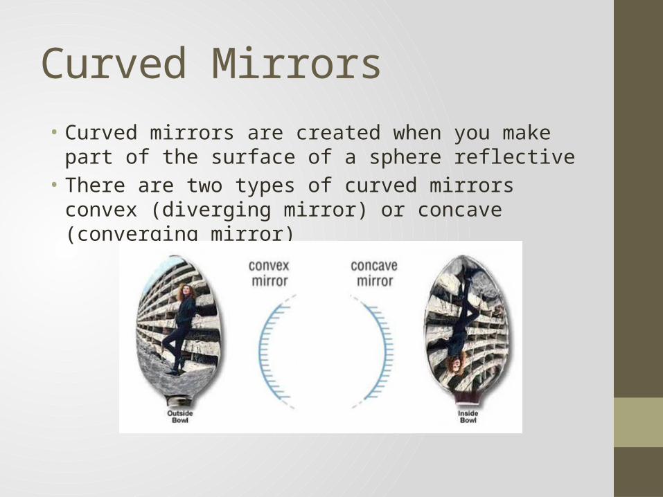
Curved Mirrors• Curved mirrors are created when you make part of the surface
of a sphere reflective• There are two types of curved mirrors convex (diverging
mirror) or concave (converging mirror)
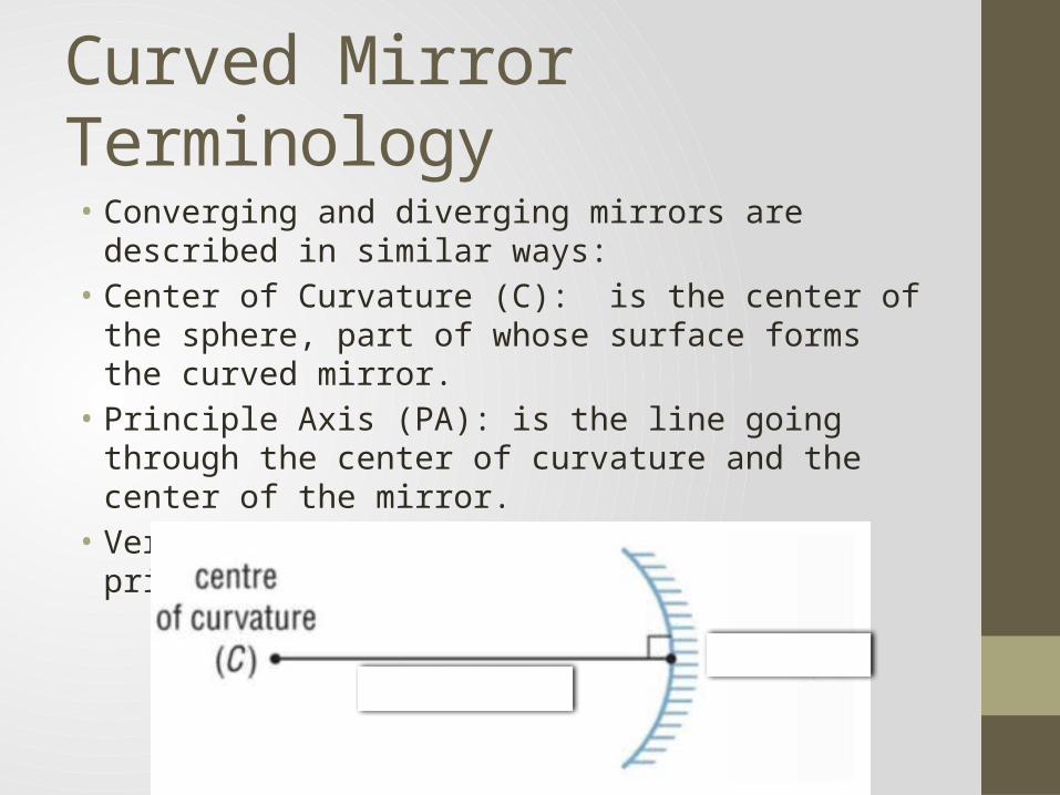
Curved Mirror Terminology• Converging and diverging mirrors are described in similar
ways:• Center of Curvature (C): is the center of the sphere, part of
whose surface forms the curved mirror.• Principle Axis (PA): is the line going through the center of
curvature and the center of the mirror.• Vertex (V): is the point where the principle axis intersects the
mirror
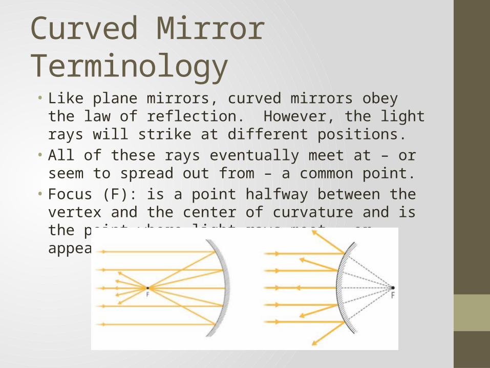
Curved Mirror Terminology• Like plane mirrors, curved mirrors obey the law of reflection.
However, the light rays will strike at different positions.• All of these rays eventually meet at – or seem to spread out
from – a common point.• Focus (F): is a point halfway between the vertex and the
center of curvature and is the point where light rays meet – or appear to spread out from.
Worksheet – Part 1• Complete Part 1 of the worksheet (Converging Mirror
Terminology) the image on the left.
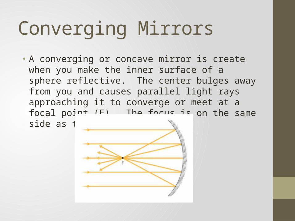
Converging Mirrors• A converging or concave mirror is create when you make the
inner surface of a sphere reflective. The center bulges away from you and causes parallel light rays approaching it to converge or meet at a focal point (F). The focus is on the same side as the object.
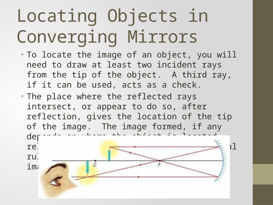
Locating Objects in Converging Mirrors• To locate the image of an object, you will need to draw at least
two incident rays from the tip of the object. A third ray, if it can be used, acts as a check.
• The place where the reflected rays intersect, or appear to do so, after reflection, gives the location of the tip of the image. The image formed, if any depends on where the object is located relative to the mirror. There are several rules we will use to help us find the image.
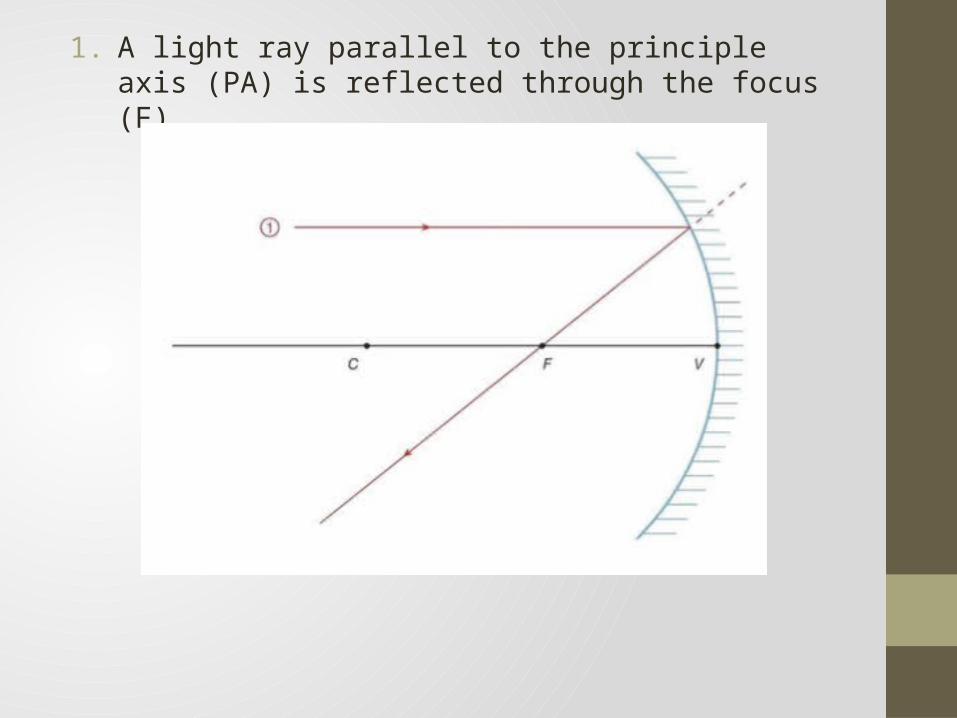
1. A light ray parallel to the principle axis (PA) is reflected through the focus (F)
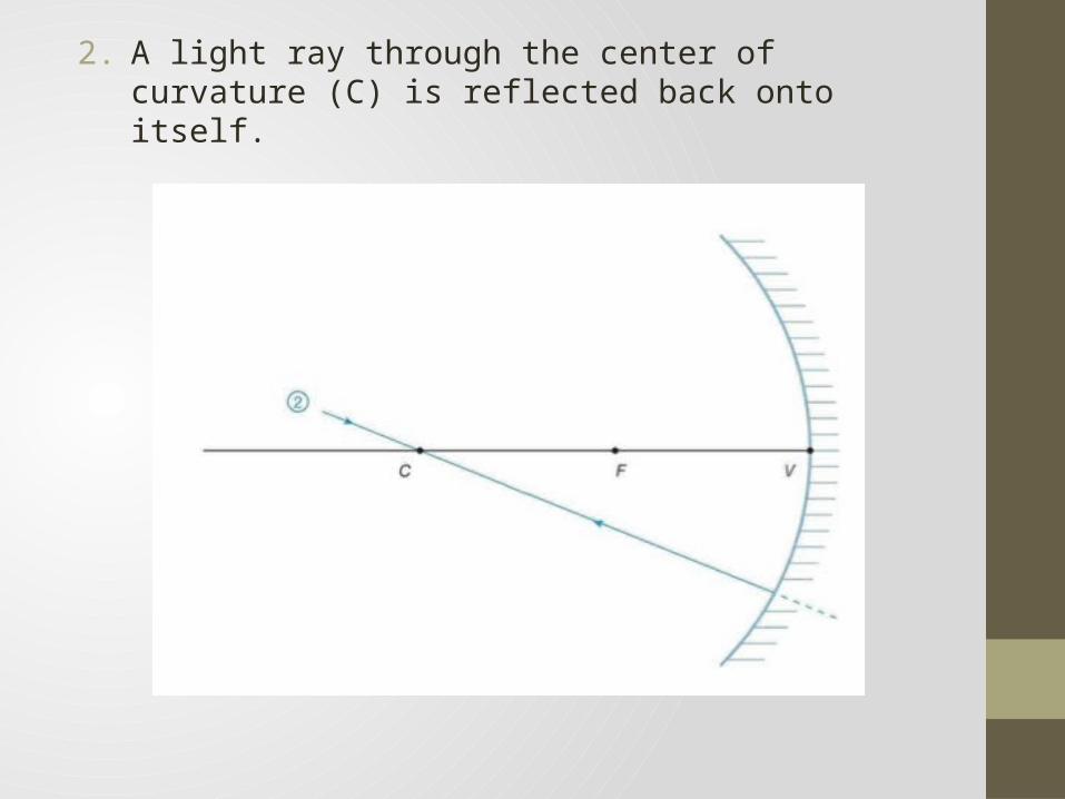
2. A light ray through the center of curvature (C) is reflected back onto itself.
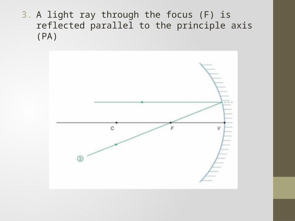
3. A light ray through the focus (F) is reflected parallel to the principle axis (PA)
Worksheet – Part 2• Complete Part 2 of the worksheet (Converging Mirror Ray
Diagram Rules). Be sure to use a ruler and a sharp pencil and to draw lightly.
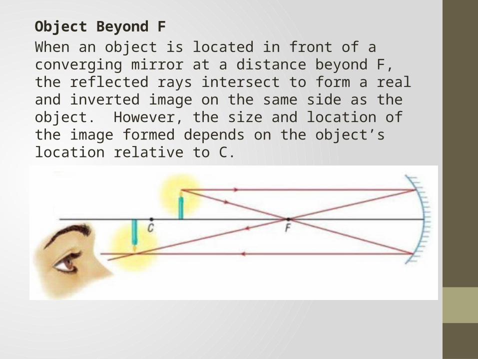
Object Beyond FWhen an object is located in front of a converging mirror at a distance beyond F, the reflected rays intersect to form a real and inverted image on the same side as the object. However, the size and location of the image formed depends on the object’s location relative to C.
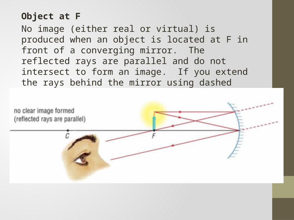
Object at FNo image (either real or virtual) is produced when an object is located at F in front of a converging mirror. The reflected rays are parallel and do not intersect to form an image. If you extend the rays behind the mirror using dashed lines, you cannot even see a virtual image.
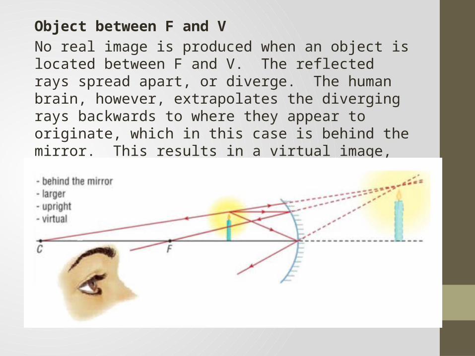
Object between F and VNo real image is produced when an object is located between F and V. The reflected rays spread apart, or diverge. The human brain, however, extrapolates the diverging rays backwards to where they appear to originate, which in this case is behind the mirror. This results in a virtual image, which you can only see by looking into the converging mirror.
Worksheet – Part 3• Complete Part 3 of the worksheet (Ray Diagrams for
Converging Mirrors). Be sure to complete the chart and Q.1 and Q.2.
NoteWhen drawing ray diagrams, remember the following:• The object (real) is always shown as a solid arrow• A real image is always drawn as a solid arrow (because real
rays were used to help locate it)• A virtual image is always shown as a dotted arrow (because
virtual rays were used to help locate it)
Worksheet – Part 3
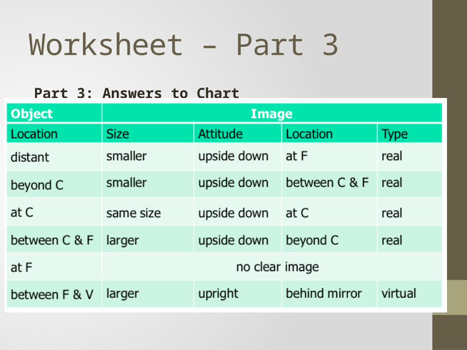
Part 3: Answers to Chart
Worksheet – Part 3
Part 3: Answers to Questions1. What is important about the first ray diagram (i.e. a distant
object)?Since the image appears at the focal point of the mirror, the distance between the image and the mirror gives you the focal length of the mirror
2. What happens to the images as the object approaches the mirror from a distance?
As the object approaches the mirror from a distance, the image (i) gets larger and (ii) moves away from the mirror
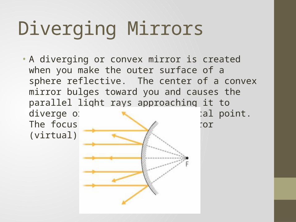
Diverging Mirrors• A diverging or convex mirror is created when you make the
outer surface of a sphere reflective. The center of a convex mirror bulges toward you and causes the parallel light rays approaching it to diverge or spread out from a focal point. The focus (F) is behind the mirror (virtual)
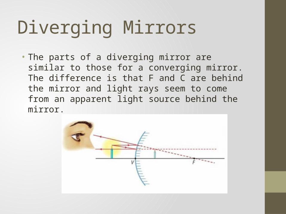
Diverging Mirrors• The parts of a diverging mirror are similar to those for a
converging mirror. The difference is that F and C are behind the mirror and light rays seem to come from an apparent light source behind the mirror.
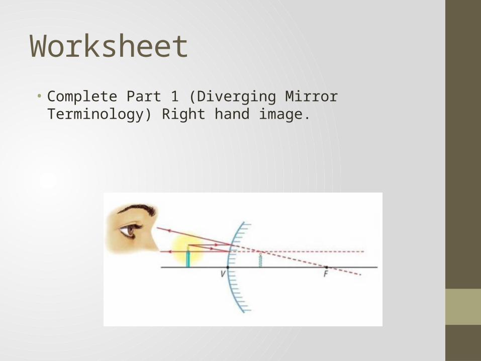
Worksheet• Complete Part 1 (Diverging Mirror Terminology) Right hand
image.
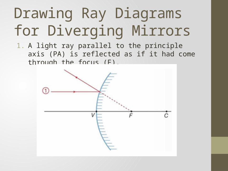
Drawing Ray Diagrams for Diverging Mirrors1. A light ray parallel to the principle axis (PA) is reflected as if it
had come through the focus (F).
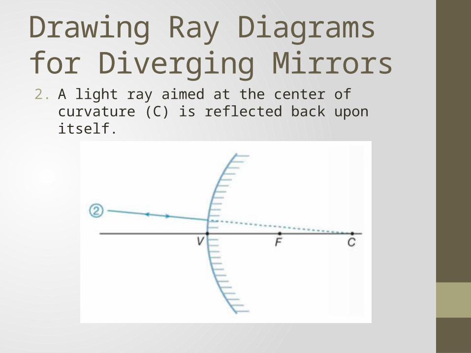
Drawing Ray Diagrams for Diverging Mirrors2. A light ray aimed at the center of curvature (C) is reflected
back upon itself.
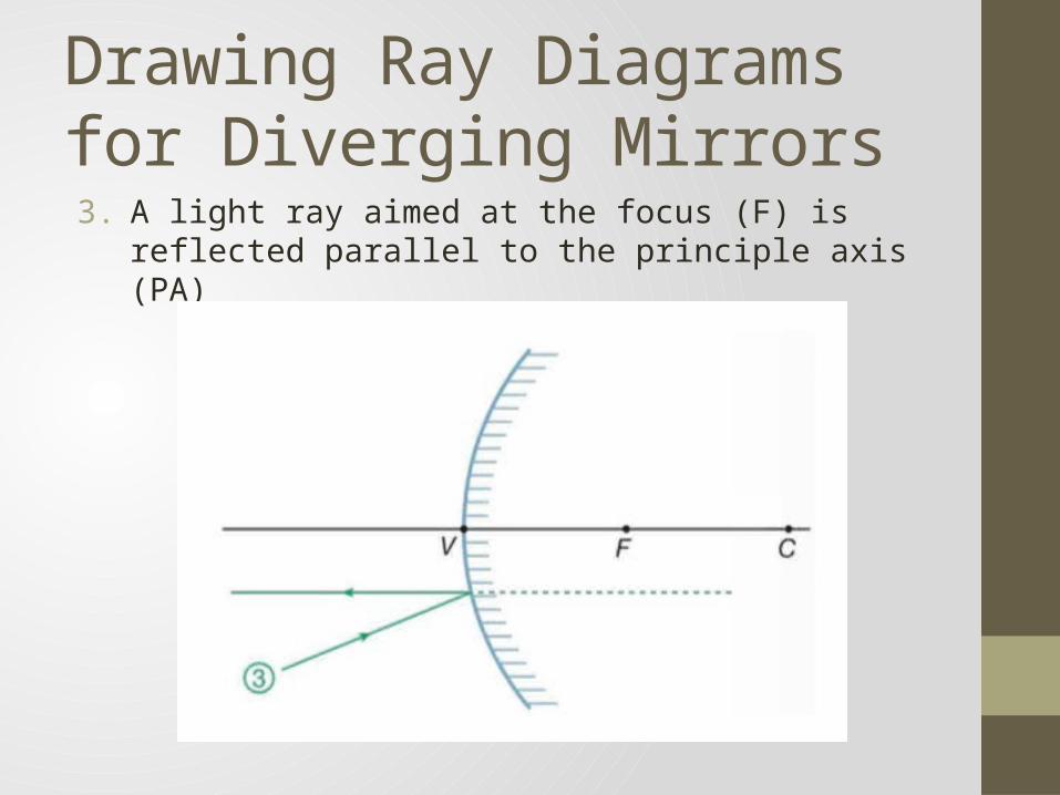
Drawing Ray Diagrams for Diverging Mirrors3. A light ray aimed at the focus (F) is reflected parallel to the
principle axis (PA)
Worksheet – Part 2• Complete Part 2 of the worksheet (Diverging Mirror Ray
Diagram Rules). Be sure to use a ruler and a sharp pencil and to draw lightly.
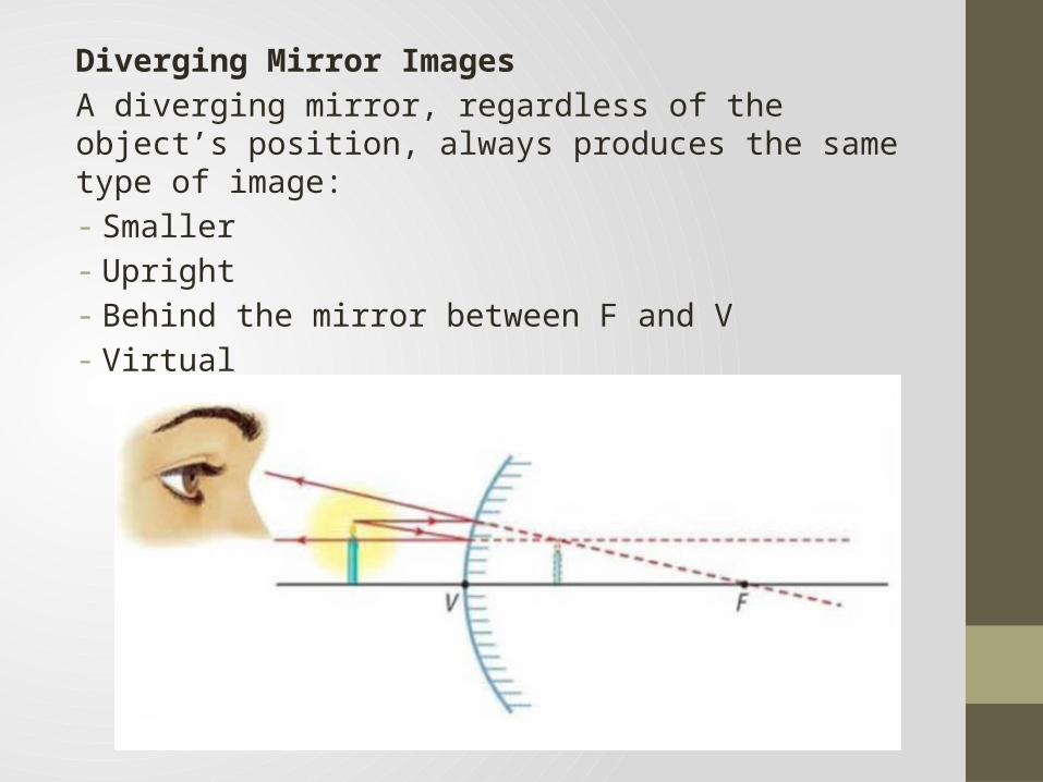
Diverging Mirror ImagesA diverging mirror, regardless of the object’s position, always produces the same type of image:- Smaller- Upright- Behind the mirror between F and V- Virtual
Worksheet – Part 4• Complete Part 4 of the worksheet (Ray Diagrams for Diverging
Mirrors).
NoteWhen drawing ray diagrams, remember the following:• The object (real) is always shown as a solid arrow• A real image is always drawn as a solid arrow (because real
rays were used to help locate it)• A virtual image is always shown as a dotted arrow (because
virtual rays were used to help locate it)