Embed Size (px)
Citation preview
SPARC-CS-12/008October 10, 2012
THE SPARC LOW LEVEL RF CONTROL SYSTEMDESIGN AND OPERATIONAL REFERENCE
Marco BellavegliaINFN, Laboratori Nazionali di Frascati, P.O. Box 13, I-00044 Frascati, Italy
Abstract
The SPARC RF low level control and synchronization system has been entirely designedand assembled in Frascati National Laboratories of INFN. This document accurately de-scribes the control system software that handles the various RF devices involved in thecited systems. The first section is dedicated to an overview of the whole SPARC controlsystem, written in LabVIEWTM developing environment. We describe the main architec-ture, where all the objects with different interfaces and functions are identically inserted.After that we give a precise description of the RFS software class, that handles the RFlow level and synchronization system and slightly differs from the other classes. In factits architecture is more complicated, because some signal acquisition and object ‘cross-talking’ problems. Also a description of the control room software is given to provide asort of operational manual for the RF low level control system user. Many upgrade on theLLRF system have been made since the beginning of the compilation of this manuscriptboth in the hardware and software architecture. Nevertheless this document can be usedas reference to understand the basic working principle of the system.
1 Introduction
This document has been realized to precisely describe the functioning of the RF low levelcontrol system of the SPARC FEL project at LNF [1], mainly from a software point ofview. In particular we want to give both an operational manual for the control room usersand a detailed reference for the RF control system developer. In section 2 we report aboutthe general control system architecture of the accelerator, that is completely designed anddeveloped in a LabVIEWTM [2] environment. Then we accurately describe the RF con-trol system, that has been developed with a structure different from the other devices, dueto some dedicated tasks it have to accomplish. This matter is discussed in section 3.1.1,that describes the main software classes that have been designed and gives the interestingcorrespondence between software and real objects. Moreover in section 3.2 we describethe tasks that the front-end CPU accomplish during each program cycle with emphasis onthe main RF control system LabVIEWTM VIs that are part of a precise software archi-tecture. Next section 3.3 is dedicated to give a sort of operator manual for the RF actionsthat one can perform using this system. We give a precise description of each softwarewindow that can be opened from the control room consoles and a “troubleshooting” as awalk trough for common problems that often occur. This document can be treated as anextension of [3], where the description of hardware devices and measurement performedusing this software are extensively treated.
2 The SPARC control system
2.1 Overview
The first part of the installation (RF gun and emittance-meter) allowed to test the archi-tecture of the control system [4] from the hardware and from the software point of view.Control application for magnetic elements, vacuum equipments, RF cavities and somediagnostics have been developed and debugged on line. In order to improve the machineoperations we have included in the system some operation service. An electronic logbookhas been used since the first phase of the operation contributing to share the informationbetween all the members of the collaboration. We began to develop an automatic systemto monitor the accelerator status periodically or when some variable is changed. This sys-tem is based on a PostgreSQL database server. The SPARC Control System is in chargeof managing devices (Tab. 1) distributed over an accelerator area. To develop the wholesystem we have short time and few people. We decided to use commercial technologiesas much as possible in order to optimize the development time. A commercial product ischaracterized by a broad distribution, which means a lot of feedback from the users and,
2

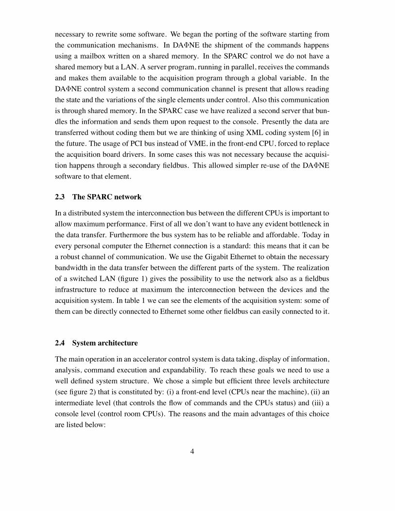
Table 1: Devices controlled in SPARC
Device e-meter SPARC InterfaceMagnet P.S 9 30 serialVacuum pump 15 23 FieldpointVacuumeter 2 6 serialModulator 2 2 EthernetRF 5 23 serial, EthernetCamera 5 12 IEEE1394Flag 5 12 Serial, CANCurrent Monitor 1 2 MultimeterPosition Monitor 0 12 Ethernet
consequently, deep debugging. Furthermore the wider is the distribution of a product themore reliable is its support from the producer. Another criterion was to privilege ‘easydevelopment and maintenance’. We decided to use:
• LabVIEW from National Instrument is used development as environment for all thesoftware;
• Industrial Personal Computer with PCI bus to house the front-end hardware.
2.2 Software
In order to reduce the time of development of the SPARC control system, we decided touse well known software. Labview became the natural choice for the following reasons:
• in the Frascati laboratory the use of National Instrument software is diffused (wecan say it is a ‘standard’);
• Labview is used as development software in the DA!NE control system [5]. Thischoice allows us to re-use, when possible, the software;
• Labview is considered reference software by a lot of hardware manufacturers thatwrite interface divers in Labview.
The DAFNE control system is working since 10 years and now is well defined and de-bugged. This encourages us in using the same architecture and software, when possible,for the SPARC control system. Analyzing the two systems we have found two maindifferences: first of all the acquisition bus is PCI for SPARC VME for DA!NE. Further-more the communication between the system levels is different. For these reasons it is
3
necessary to rewrite some software. We began the porting of the software starting fromthe communication mechanisms. In DA!NE the shipment of the commands happensusing a mailbox written on a shared memory. In the SPARC control we do not have ashared memory but a LAN. A server program, running in parallel, receives the commandsand makes them available to the acquisition program through a global variable. In theDA!NE control system a second communication channel is present that allows readingthe state and the variations of the single elements under control. Also this communicationis through shared memory. In the SPARC case we have realized a second server that bun-dles the information and sends them upon request to the console. Presently the data aretransferred without coding them but we are thinking of using XML coding system [6] inthe future. The usage of PCI bus instead of VME, in the front-end CPU, forced to replacethe acquisition board drivers. In some cases this was not necessary because the acquisi-tion happens through a secondary fieldbus. This allowed simpler re-use of the DA!NEsoftware to that element.
2.3 The SPARC network
In a distributed system the interconnection bus between the different CPUs is important toallow maximum performance. First of all we don’t want to have any evident bottleneck inthe data transfer. Furthermore the bus system has to be reliable and affordable. Today inevery personal computer the Ethernet connection is a standard: this means that it can bea robust channel of communication. We use the Gigabit Ethernet to obtain the necessarybandwidth in the data transfer between the different parts of the system. The realizationof a switched LAN (figure 1) gives the possibility to use the network also as a fieldbusinfrastructure to reduce at maximum the interconnection between the devices and theacquisition system. In table 1 we can see the elements of the acquisition system: some ofthem can be directly connected to Ethernet some other fieldbus can easily connected to it.
2.4 System architecture
The main operation in an accelerator control system is data taking, display of information,analysis, command execution and expandability. To reach these goals we need to use awell defined system structure. We chose a simple but efficient three levels architecture(see figure 2) that is constituted by: (i) a front-end level (CPUs near the machine), (ii) anintermediate level (that controls the flow of commands and the CPUs status) and (iii) aconsole level (control room CPUs). The reasons and the main advantages of this choiceare listed below:
4
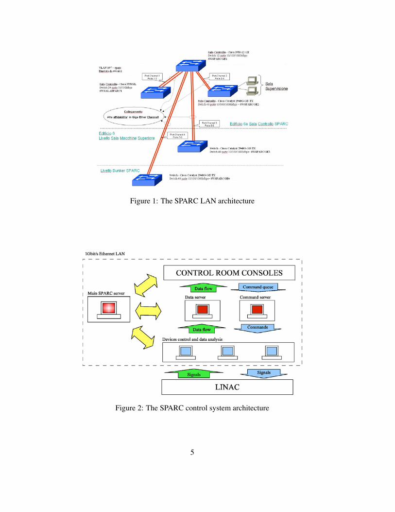
Figure 1: The SPARC LAN architecture
Figure 2: The SPARC control system architecture
5
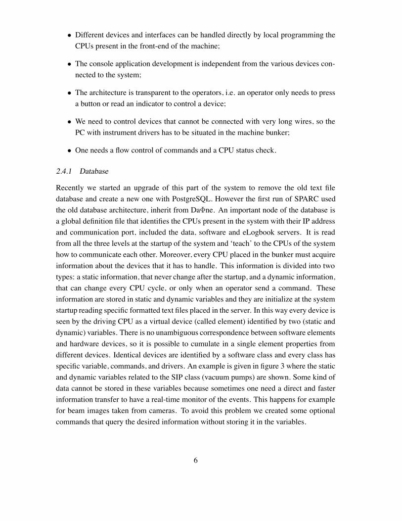
• Different devices and interfaces can be handled directly by local programming theCPUs present in the front-end of the machine;
• The console application development is independent from the various devices con-nected to the system;
• The architecture is transparent to the operators, i.e. an operator only needs to pressa button or read an indicator to control a device;
• We need to control devices that cannot be connected with very long wires, so thePC with instrument drivers has to be situated in the machine bunker;
• One needs a flow control of commands and a CPU status check.
2.4.1 Database
Recently we started an upgrade of this part of the system to remove the old text filedatabase and create a new one with PostgreSQL. However the first run of SPARC usedthe old database architecture, inherit from Da!ne. An important node of the database isa global definition file that identifies the CPUs present in the system with their IP addressand communication port, included the data, software and eLogbook servers. It is readfrom all the three levels at the startup of the system and ‘teach’ to the CPUs of the systemhow to communicate each other. Moreover, every CPU placed in the bunker must acquireinformation about the devices that it has to handle. This information is divided into twotypes: a static information, that never change after the startup, and a dynamic information,that can change every CPU cycle, or only when an operator send a command. Theseinformation are stored in static and dynamic variables and they are initialize at the systemstartup reading specific formatted text files placed in the server. In this way every device isseen by the driving CPU as a virtual device (called element) identified by two (static anddynamic) variables. There is no unambiguous correspondence between software elementsand hardware devices, so it is possible to cumulate in a single element properties fromdifferent devices. Identical devices are identified by a software class and every class hasspecific variable, commands, and drivers. An example is given in figure 3 where the staticand dynamic variables related to the SIP class (vacuum pumps) are shown. Some kind ofdata cannot be stored in these variables because sometimes one need a direct and fasterinformation transfer to have a real-time monitor of the events. This happens for examplefor beam images taken from cameras. To avoid this problem we created some optionalcommands that query the desired information without storing it in the variables.
6
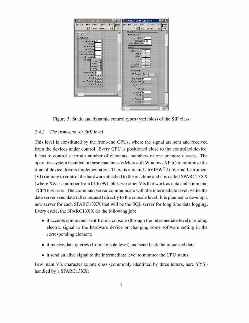
Figure 3: Static and dynamic control types (variables) of the SIP class
2.4.2 The front-end (or 3rd) level
This level is constituted by the front-end CPUs, where the signal are sent and receivedfrom the devices under control. Every CPU is positioned close to the controlled device.It has to control a certain number of elements, members of one or more classes. Theoperative system installed in these machines is Microsoft WindowsXP c! to minimize thetime of device drivers implementation. There is a main LabVIEWTM Virtual Instrument(VI) running to control the hardware attached to the machine and it is called SPARC13XX(where XX is a number from 01 to 99), plus two other VIs that work as data and commandTCP/IP servers. The command server communicate with the intermediate level, while thedata server send data (after request) directly to the console level. It is planned to develop anew server for each SPARC13XX that will be the SQL server for long time data logging.Every cycle, the SPARC13XX do the following job:
• it accepts commands sent from a console (through the intermediate level), sendingelectric signal to the hardware device or changing some software setting in thecorresponding element;
• it receive data queries (from console level) and send back the requested data
• it send an alive signal to the intermediate level to monitor the CPU status.
Few main VIs characterize one class (commonly identified by three letters, here YYY)handled by a SPARC13XX:
7
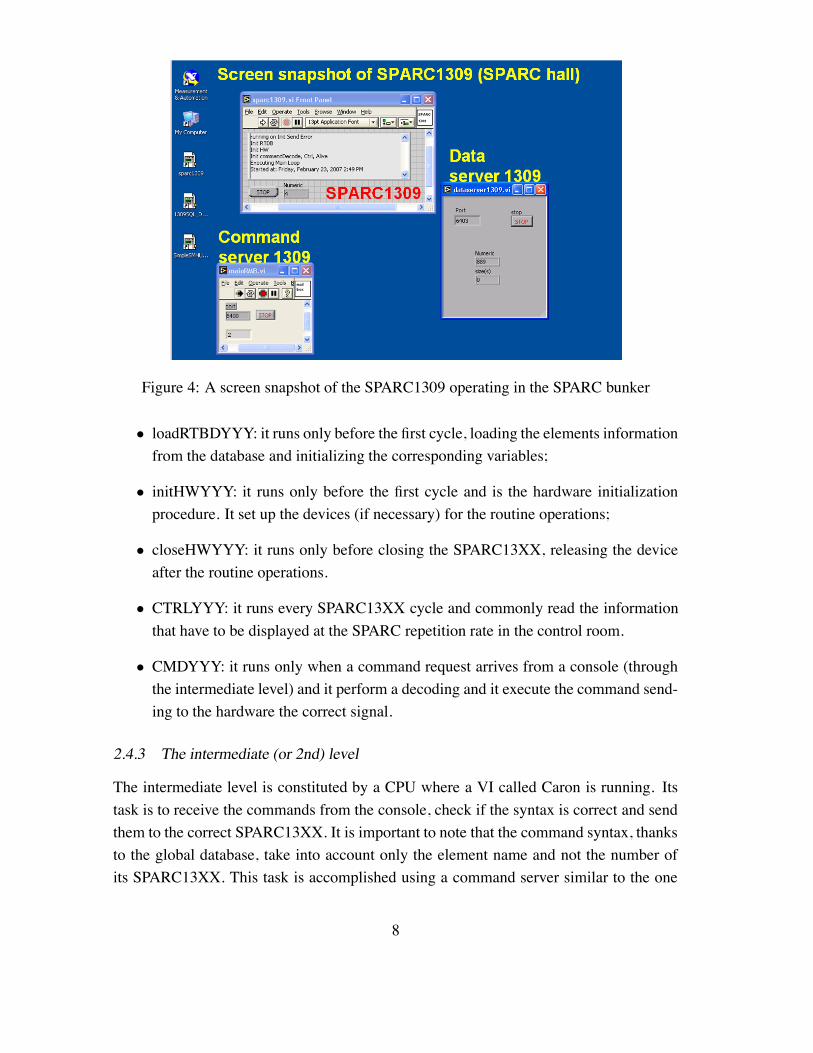
Figure 4: A screen snapshot of the SPARC1309 operating in the SPARC bunker
• loadRTBDYYY: it runs only before the first cycle, loading the elements informationfrom the database and initializing the corresponding variables;
• initHWYYY: it runs only before the first cycle and is the hardware initializationprocedure. It set up the devices (if necessary) for the routine operations;
• closeHWYYY: it runs only before closing the SPARC13XX, releasing the deviceafter the routine operations.
• CTRLYYY: it runs every SPARC13XX cycle and commonly read the informationthat have to be displayed at the SPARC repetition rate in the control room.
• CMDYYY: it runs only when a command request arrives from a console (throughthe intermediate level) and it perform a decoding and it execute the command send-ing to the hardware the correct signal.
2.4.3 The intermediate (or 2nd) level
The intermediate level is constituted by a CPU where a VI called Caron is running. Itstask is to receive the commands from the console, check if the syntax is correct and sendthem to the correct SPARC13XX. It is important to note that the command syntax, thanksto the global database, take into account only the element name and not the number ofits SPARC13XX. This task is accomplished using a command server similar to the one
8
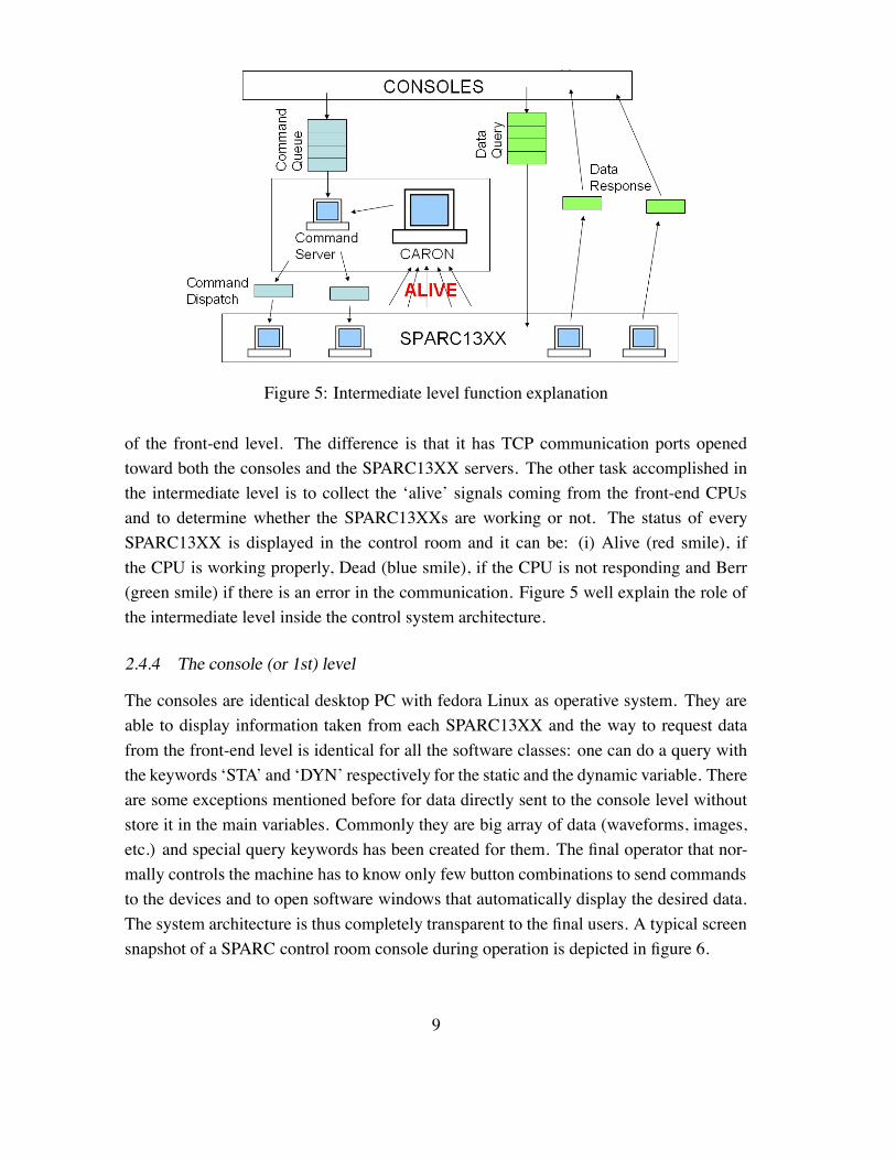
Figure 5: Intermediate level function explanation
of the front-end level. The difference is that it has TCP communication ports openedtoward both the consoles and the SPARC13XX servers. The other task accomplished inthe intermediate level is to collect the ‘alive’ signals coming from the front-end CPUsand to determine whether the SPARC13XXs are working or not. The status of everySPARC13XX is displayed in the control room and it can be: (i) Alive (red smile), ifthe CPU is working properly, Dead (blue smile), if the CPU is not responding and Berr(green smile) if there is an error in the communication. Figure 5 well explain the role ofthe intermediate level inside the control system architecture.
2.4.4 The console (or 1st) level
The consoles are identical desktop PC with fedora Linux as operative system. They areable to display information taken from each SPARC13XX and the way to request datafrom the front-end level is identical for all the software classes: one can do a query withthe keywords ‘STA’ and ‘DYN’ respectively for the static and the dynamic variable. Thereare some exceptions mentioned before for data directly sent to the console level withoutstore it in the main variables. Commonly they are big array of data (waveforms, images,etc.) and special query keywords has been created for them. The final operator that nor-mally controls the machine has to know only few button combinations to send commandsto the devices and to open software windows that automatically display the desired data.The system architecture is thus completely transparent to the final users. A typical screensnapshot of a SPARC control room console during operation is depicted in figure 6.
9
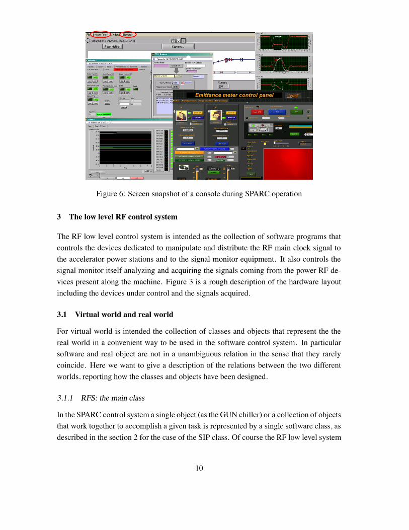
Figure 6: Screen snapshot of a console during SPARC operation
3 The low level RF control system
The RF low level control system is intended as the collection of software programs thatcontrols the devices dedicated to manipulate and distribute the RF main clock signal tothe accelerator power stations and to the signal monitor equipment. It also controls thesignal monitor itself analyzing and acquiring the signals coming from the power RF de-vices present along the machine. Figure 3 is a rough description of the hardware layoutincluding the devices under control and the signals acquired.
3.1 Virtual world and real world
For virtual world is intended the collection of classes and objects that represent the thereal world in a convenient way to be used in the software control system. In particularsoftware and real object are not in a unambiguous relation in the sense that they rarelycoincide. Here we want to give a description of the relations between the two differentworlds, reporting how the classes and objects have been designed.
3.1.1 RFS: the main class
In the SPARC control system a single object (as the GUN chiller) or a collection of objectsthat work together to accomplish a given task is represented by a single software class, asdescribed in the section 2 for the case of the SIP class. Of course the RF low level system
10
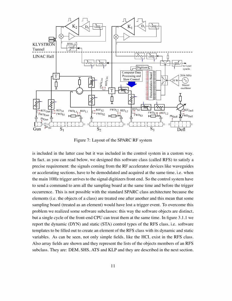
Figure 7: Layout of the SPARC RF system
is included in the latter case but it was included in the control system in a custom way.In fact, as you can read below, we designed this software class (called RFS) to satisfy aprecise requirement: the signals coming from the RF accelerator devices like waveguidesor accelerating sections, have to be demodulated and acquired at the same time, i.e. whenthe main 10Hz trigger arrives to the signal digitizers front end. So the control system haveto send a command to arm all the sampling board at the same time and before the triggeroccurrence. This is not possible with the standard SPARC class architecture because theelements (i.e. the objects of a class) are treated one after another and this mean that somesampling board (treated as an element) would have lost a trigger event. To overcome thisproblem we realized some software subclasses: this way the software objects are distinct,but a single cycle of the front-end CPU can treat them at the same time. In figure 3.1.1 wereport the dynamic (DYN) and static (STA) control types of the RFS class, i.e. softwaretemplates to be filled out to create an element of the RFS class with its dynamic and staticvariables. As can be seen, not only simple fields, like the HCI, exist in the RFS class.Also array fields are shown and they represent the lists of the objects members of an RFSsubclass. They are: DEM, SHS, ATS and KLP and they are described in the next section.
11
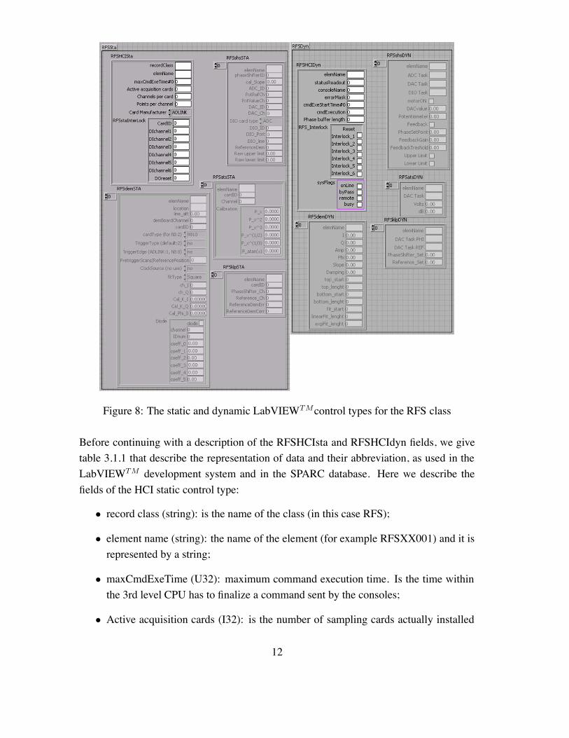
Figure 8: The static and dynamic LabVIEWTMcontrol types for the RFS class
Before continuing with a description of the RFSHCIsta and RFSHCIdyn fields, we givetable 3.1.1 that describe the representation of data and their abbreviation, as used in theLabVIEWTM development system and in the SPARC database. Here we describe thefields of the HCI static control type:
• record class (string): is the name of the class (in this case RFS);
• element name (string): the name of the element (for example RFSXX001) and it isrepresented by a string;
• maxCmdExeTime (U32): maximum command execution time. Is the time withinthe 3rd level CPU has to finalize a command sent by the consoles;
• Active acquisition cards (I32): is the number of sampling cards actually installed
12
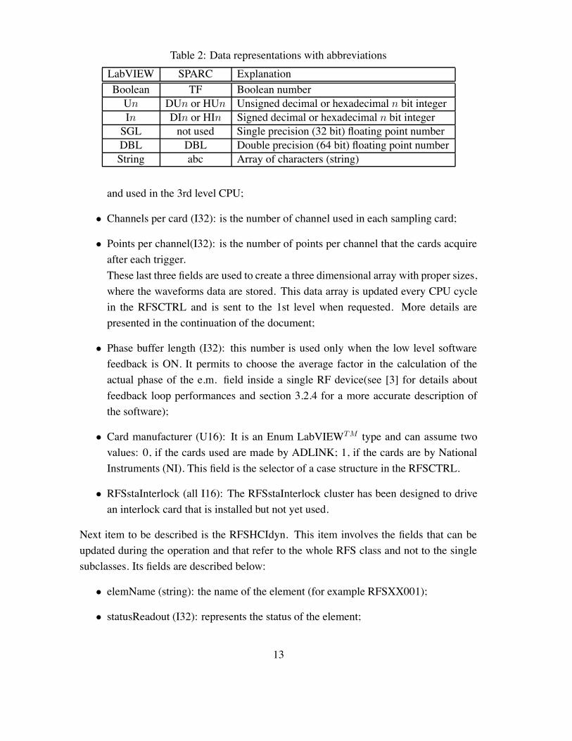
Table 2: Data representations with abbreviationsLabVIEW SPARC ExplanationBoolean TF Boolean numberUn DUn or HUn Unsigned decimal or hexadecimal n bit integerIn DIn or HIn Signed decimal or hexadecimal n bit integerSGL not used Single precision (32 bit) floating point numberDBL DBL Double precision (64 bit) floating point numberString abc Array of characters (string)
and used in the 3rd level CPU;
• Channels per card (I32): is the number of channel used in each sampling card;
• Points per channel(I32): is the number of points per channel that the cards acquireafter each trigger.These last three fields are used to create a three dimensional array with proper sizes,where the waveforms data are stored. This data array is updated every CPU cyclein the RFSCTRL and is sent to the 1st level when requested. More details arepresented in the continuation of the document;
• Phase buffer length (I32): this number is used only when the low level softwarefeedback is ON. It permits to choose the average factor in the calculation of theactual phase of the e.m. field inside a single RF device(see [3] for details aboutfeedback loop performances and section 3.2.4 for a more accurate description ofthe software);
• Card manufacturer (U16): It is an Enum LabVIEWTM type and can assume twovalues: 0, if the cards used are made by ADLINK; 1, if the cards are by NationalInstruments (NI). This field is the selector of a case structure in the RFSCTRL.
• RFSstaInterlock (all I16): The RFSstaInterlock cluster has been designed to drivean interlock card that is installed but not yet used.
Next item to be described is the RFSHCIdyn. This item involves the fields that can beupdated during the operation and that refer to the whole RFS class and not to the singlesubclasses. Its fields are described below:
• elemName (string): the name of the element (for example RFSXX001);
• statusReadout (I32): represents the status of the element;
13
• consoleName (I32): this field represent the number of the console that is remotecontrolling the element. In the SPARC control system it is not used.
• errorMask (I32): this field contain information about the type and the location ofan error (if occured).
• cmdExeStartTime (I32): this is not used in the RFS class;
• cmdExecution (I32): this is not used in the RFS class;
• RFS Interlock (all Boolean): this cluster has been designed to drive an interlockcard that is installed but not yet used;
• sysFlags (all Boolean): every class has this cluster field. It gives to the system acommunication about the status of any virtual object. In the SPARC control systemthis cluster is rarely updated. Here is reported a short description of the clusterboolean items:
onLine: the element is fully operational if tis field is TRUE (the default state);
byPass: the element is not controlled in the 3rd level CPU cycle if this field isTRUE;
remote: if TRUE (as default) it is possible to control to the element from re-mote consoles;
busy: if TRUE the element can not execute a new command.
3.1.2 Subclasses
The RFS subclasses are arrays of clusters placed inside the main RFS static and dynamiccontrol type. Each element of the array represents an element of a subclass. Since thisarchitecture is an extension of the main control system architecture, the subclasses are notrecognized at the global level, that only can address commands and request informationconcerning the main RFS class. So a more complex command syntax and dynamic dataupdate has been designed for the RFS environment, respect to the standard classes. Thesedifferences are extensively treated in the next 3.2 and 3.3 sections. Here we present thestatic and dynamic field description of the 4 RFS subclasses.
DEM: DEMoulator This subclass element represents more than a single real device.In fact, as shown below, it refers to: electronic S-band mixers, RF peak detectors, RFpower devices and cables and sampling boards. A detailed description of a RFSdemSTAelement is here reported:
14
• elemName (string): the name of the subelement;
• location (string): the location where a probe is inserted to acquire and analyze asignal;
• line att (DBL): line attenuation. It is the sum of the calibrated RF devices (direc-tional couplers, cables, fixed attenuators) from the signal location to the hardwarefront-end;
• demBoardChannel (I16): it is the channel used in the demodulation board (see [3])to process the incoming signal;
• cardID (I16): it is the ID number of the sampling card used to acquire the demodu-lated signal;
• cardType (U16): this field is used to determine which kind of digitizer is usedto acquire a signal. For NI DAQ cards PXI5105 (60Msamples/s, 12bit) it simplyassume the value of 2, for ADLINK cards it can be 0 if the digitizer is the PCI9810(20Msamples/s, 10bit), 1 if the digitizer is the PCI9812 (20Msamples/s, 12bit) and2 is the digitizer is the PCI9820 (60Msamples/s, 14bit);
• Trigger Type (U16): it is normally set to the default value (2, external trigger)and one can change it if needed. In this case one has to take care during the fieldmodification, because the Enum strings are relative only to the ADLINK cards. Onecan refer to the acquisition VIs in the RFSCTRL (see section 3.2.4) to acquire theneeded informations about NI cards;
• Trigger Edge (U16): also in this case one must avoid errors due to the Enum stringsthat refers only at the ADLINK case. Nevertheless this field is normally set to thedefault (1 for ADLINK and 0 for NI), and it don’t need to be modified;
• PretriggerScans/ReferencePosition (U32): this field has a double mean. The Pre-trigger scans refer to the ADLINK cards and represent the number of points shownbefore the trigger occurs. Reference position is relative to the NI cards and it isthe position of the signal acquired respect to the trigger event and it is expressed inpercentage (50 means that the same quantity of data are acquired before and afterthe trigger event, 1 is the default and it means that all the data are acquired after thetrigger event);
• ClockSource (U16): it is no more utilized because the sampling clock is perma-nently set to internal both for NI and ADLINK cards;
15
• fitType (U16): this item refers to the signal analysis after the acquisition and permitto choose if an exponential fit (needed for decaying field signal, for example) or asimple average (needed for square pulses, for example) is performed;
• ch I (I16): the sampling card channel used to acquire the part of the demodulatedsignal in phase (I) with the original one;
• ch Q (I16): the sampling card channel used to acquire the part of the demodulatedsignal in quadrature (Q) with the original one;
• Cal K I (DBL): it is a calibration coefficient relative to the RF mixer used to demod-ulate the signal and it is used in the algorithm of phase and amplitude calculation toovercome systematic errors;
• Cal K Q (DBL): same as the previous;
• Cal Phi 0 (DBL): same as the previous;
• Diode (cluster): this cluster is used if we acquire the signal coming from a peakdetector that substitute the RF mixer, but only measure the amplitude of the signal.The contents of the cluster is described below:
diode (Boolean): it is TRUE if a peak detector is used to process the signal;
channel (I16): it is the number of the channel of the sampling card used by thissubelement;
IDnum (I16): is the ID number of the diode;
coeff 0 ÷ coeff 5 (DBL): these are calibration coefficient and they are relativeto a polynomial used to fit the calibration data of the diode. They are used to obtainthe correct amplitude value starting from the measured voltage.
Now we describe the RFSdemDYN that represent the part of the DEM subelement. It canbe updated during the operations automatically (see section 3.2.4) or after a commandexecution (see section 3.2.5)
• elemName (string): the name of the subelement;
• I (DBL): it is a number representing the part of the demodulated signal in phasewith the original one and it is calculated during each 3rd level CPU cycle;
• Q (DBL): it is a number rep resenting the part of the demodulated signal in quadra-ture with the original one and it is calculated during each 3rd level CPU cycle;
16
• Amp (DBL): it is a number representing the amplitude of the signal calculated fromthe I and Q values during each CPU cycle;
• Phi (DBL): it is a number representing the phase of the signal calculated from the Iand Q values during each CPU cycle;
• Slope (DBL): if a strait line is used to fit the RF pulse phase behavior, this is the theslope of that line;
• Damping (DBL): if an exponential curve is used to fit the amplitude of an RF pulse,this represents the damping factor that appear in the exponent;
• top start, top length (I16): modifying these items, one is able to choose the partof the signal where an average is performed to calculate a number representing theflat top of a square RF pulse. They are used in combination with bottom start andbottom length to calculate Amp and Phi. These fields are integers because theyexpress the samples number (see section 3.2.4);
• bottom start, bottom length (I16): modifying these items, one is able to choose thepart of the signal where an average is performed to calculate a number representingthe area where the RF pulse is not present. These fields are integers because theyexpress the samples number;
• fit start, linearFit length, expFit length (I16): they are used in the same way astop start and top length, but they concern the case of an exponential fit performedon the RF demodulated pulse. They are used in combination with bottom start andbottom length to calculate Slope and Damping (see section 3.2.4);
SHS: phase SHifter at Signal level The SHS subclass represents the signal phaseshifters placed in the SPARC hall and with the features of accepting incoming commandsto move forward or reverse and performing an automatic phase locking movement whenthe software feedback system is ON (see [3] and section 3.2.4). The RFSshsSTA elementcontroltype is described below:
• elemName (string): name of the SHS subelement;
• phaseShifterID (U32): the ID number of the phase shifter (visible in the boardinside the SPARC hall rack);
• cal Slope (DBL): the calibration coefficient (potentiometer reading VS phase shift);
17
• ADC ID (U32): the ID number of the ADC reading the motor potentiometer;
• PotRefCh (U32): the channel of the ADC used to read the fixed voltage (about 10V)applied to the potentiometer;
• PotValueCh (U32): the channel of the ADC used to read the voltage at the po-tentiometer central pin. Togheter with the previous field it is used to calculate thepotentiometer changing voltage in a way not sensitive to the main voltage fluctua-tions (see section 3.2.4);
• DAC ID (U32): the ID number of the DAC controlling the DC motor;
• DAC Ch (U32): the channel of the DAC used to control the DC motor;
• DIO card type (U16): this field has to be set properly depending on the type of card(ADC or DAC) where the digital input and output are located. It is only used in thecase of NI cards;
• DIO ID (U32): the ID number of the digital input and output card used to switchON or OFF the phase shifter DC motor(acting on PWN driver electronic card in-puts);
• Dio Port (U32): the port of the DIO used to switch ON or OFF the DC motor;
• Dio line (U32): the line of the DIO port used to turn ON or OFF the DC motor;
• Gain (DBL): the gain of the software phase feedback loop (see section 3.2.4);
• ReferenceDem (U32): the number of the DEM subelement where the phase is readto calculate the error signal in the feedback loop. The reference DEM has to belocated on the same CPU of the SHS;
• Raw upper limit(DBL): is the software upper limit switch implemented only to givean alarm to the operator in the control room and not to stop the motor. It is expressedin volts and it is the maximum value that potentiometer can assume minus the 1%of the total phase excursion (that is about 520!);
• Raw lower limit(DBL): is the software lower limit switch implemented only to givean alarm to the operator in the control room and not to stop the motor. It is expressedin volts and it is the minimum value that the potentiometer can assume plus its 1%of the total phase excursion (that is about 520!);
Here the RFSshsDYN element control type is presented:
18
• elemName (string): it is the DEM subelement name;
• ADC task (string): it is used only with NI cards and it is the task opened at the first3rd level CPU cycle to make available the ADC inputs;
• DAC task (string): it is used only with NI cards and it is the task opened at the first3rd level CPU cycle to make available the DAC outputs;
• DAC task (string): it is used only with NI cards and it is the task opened at the first3rd level CPU cycle to make available the DIO;
• motorON (Boolean): it is TRUE if the motor is switched ON and ready to move;
• DACvalue (DBL): the actual set of the PWM motor driver control voltage;
• Potentiometer (DBL): the actual absolute position of the motor expressed in degreesof RF phase;
• LockedPhase (DBL): the phase to follow in the software feedback loop;
• Feedback (Boolean): it is TRUE if the software phase feedback is ON;
• Upper Limit (Boolean): it is TRUE if the software upper limit is reached;
• Lower Limit (Boolean): it is TRUE if the software lower limit is reached.
ATS: ATtenuator at Signal level The signal level attenuators are represented in thecontrol system by the subclass ATS. They are electronic voltage controlled attenuatorsand change their state when a command is executed, when an error occurs or when the3rd level CPU is turned OFF. The Static control type RFSatsSTA is described below:
• elemName (string): the ATS subelement name;
• cardID (U32): the ID number of the DAC that controls the attenuator;
• Channel (U32): the channel of the DAC that controls the attenuator;
• Calibration (cluster of DBL): here are reported the calibration coefficient that areused to convert the dB setting wanted by the operator into a proper voltage sentto the device. The algorithm is more complex than a simple polynomial due to thestrong not linearity of the attenuators characteristic: V = P0dB+P1dB2+P2dB3+
P3dB1/2 + P4dB1/3 + P5 arctan dB;
19
The dynamic control type RFSatsDYN has the fields reported below:
• elemName (string): the ATS subelement name;
• DAC task (string): it is used only with NI cards and it is the task opened at the first3rd level CPU cycle to make available the DAC outputs;
• Volts (DBL): the actual volts set at the DAC output;
• dB (DBL): the actual set attenuation.
KLP: Klystron phase feedback LooP The klystron fast electronic phase locking loop(see [3] for details) need some remote knob to be properly close the loop, so it is includedin the control system inside the subclass KLP. The static control type is here described:
• elemName(string): the KLP subelement name;
• card ID (U32): the ID number of the DAC card;
• PhaseShifter Ch (U32): the DAC channel used to control an electronic phase shifterthat close the loop;
• Reference Ch (U32): the DAC channel used to control the bias voltage of the am-plification stages;
• ReferenceDemErr (U32): the number of the DEM subelement that acquire the errorsignal of the feedback loop;
• ReferenceDem Corr (U32): the number of the DEM subelement that acquire thecorrection signal of the feedback loop.
The description of the RFSklpDYN control type is reported below:
• elemName (string): the name of the KLP subelement;
• Dac Task PHI, Dac Task REF (string): it is used only with NI cards and it is thetask opened at the first 3rd level CPU cycle to make available the DAC outputs;
• PhaseShifter Set (DBL): the voltage set at the DAC output controlling the phaseshifter;
• Reference Set (DBL): the voltage set at the DAC output controlling the bias voltage.
20
3.1.3 RFS data types
In the RFS class, there are 3 types of data that can be requested from a console: they areSTA, DYN, WAV. The request is made in the same way than the other classes sendingto the data server the correct command. The STA and DYN data types simply representthe RFS main class static and dynamic control types, respectively. The WAV data typerepresents the three dimensional array that each RFS 3rd level CPU updates every cycleand where the acquired raw waveform data from all the active sampling card are stored.
3.2 The 3rd level VIs: a manual for the developer
In the SPARC control system the 3rd level is the real interface with instruments anddevices of various types. The 3rd level CPUs control the objects as they are definedin the control system and normally read informations every cycle about the device statusand execute commands that change the status. Only often these CPUs are used to performa first information processing executing simple algorithms on the acquired data duringeach cycle.
3.2.1 Overview and actual hardware arrangement
Actually, the SPARC photo-injector is working in its final configuration and all the hard-ware, included the RF system one, is installed and functioning. In particular, the RFSclass is using two 3rd level CPUs that are named SPARC1306 and SPARC1307 that re-spectively controls the RFSXX002 and RFSXX001 elements. The SPARC1306 is in-stalled in the accelerator hall and it has to accomplish the following tasks: (i) signal phaseshifter control; (ii) implementation of the slow phase feedback; (iii) acquisition of the de-modulated signals from the linac RF devices using the sampling cards NI PXI 5105; (iv) afirst data analysis to extrapolate amplitude and phase of the acquired signals. So, the sub-classes used in the SPARC1306 are SHS and DEM. The second CPU, the SPARC1307, isinstalled in the RF power station hall and it has to finalize the following tasks: (i) signalattenuator control; (ii) acquisition of the demodulated signals coming from the waveguidedirectional coupler just after the klystrons output and from the fast phase feedback loop(the sampling cards are in this case ADLINK 9812); (iii) klystron loop working pointremote control. The subclasses involved in the SPARC1307 tasks are DEM, ATS andKLP.
21
3.2.2 RFSLoadRTDB, GRFSsta and GRFSdyn: loading the database and handling globalvariables
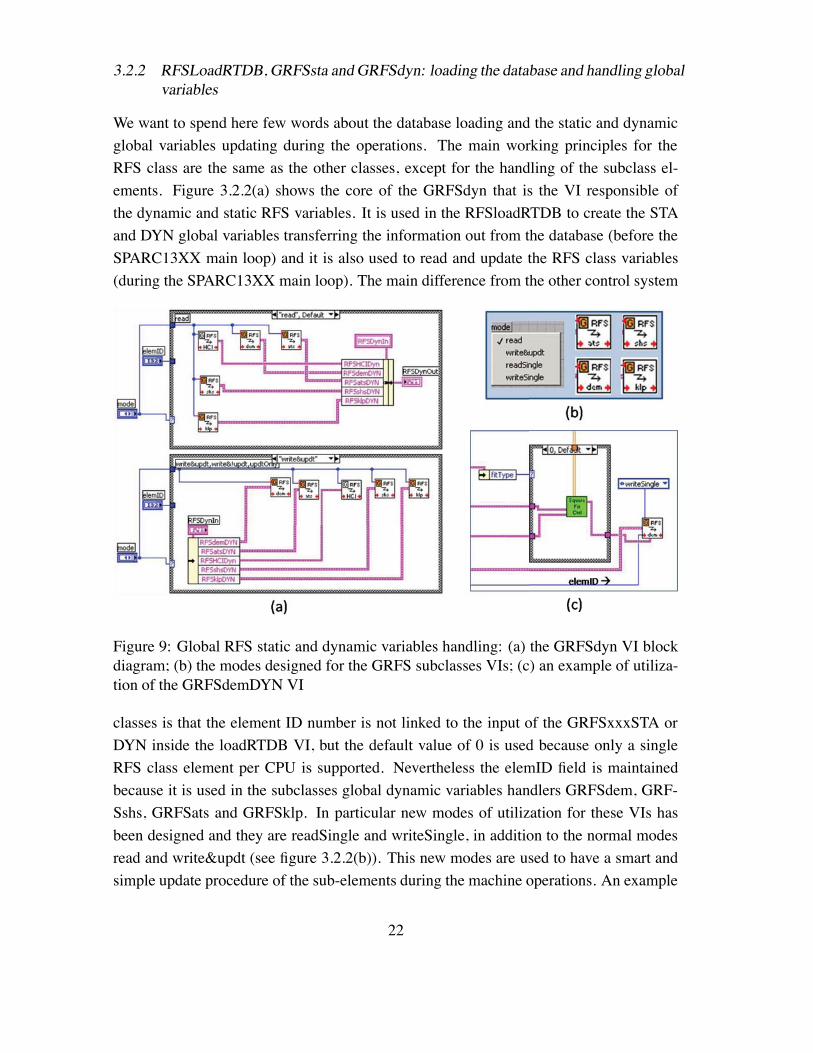
We want to spend here few words about the database loading and the static and dynamicglobal variables updating during the operations. The main working principles for theRFS class are the same as the other classes, except for the handling of the subclass el-ements. Figure 3.2.2(a) shows the core of the GRFSdyn that is the VI responsible ofthe dynamic and static RFS variables. It is used in the RFSloadRTDB to create the STAand DYN global variables transferring the information out from the database (before theSPARC13XX main loop) and it is also used to read and update the RFS class variables(during the SPARC13XX main loop). The main difference from the other control system
Figure 9: Global RFS static and dynamic variables handling: (a) the GRFSdyn VI blockdiagram; (b) the modes designed for the GRFS subclasses VIs; (c) an example of utiliza-tion of the GRFSdemDYN VI
classes is that the element ID number is not linked to the input of the GRFSxxxSTA orDYN inside the loadRTDB VI, but the default value of 0 is used because only a singleRFS class element per CPU is supported. Nevertheless the elemID field is maintainedbecause it is used in the subclasses global dynamic variables handlers GRFSdem, GRF-Sshs, GRFSats and GRFSklp. In particular new modes of utilization for these VIs hasbeen designed and they are readSingle and writeSingle, in addition to the normal modesread and write&updt (see figure 3.2.2(b)). This new modes are used to have a smart andsimple update procedure of the sub-elements during the machine operations. An example
22
of this usage is shown in figure 3.2.2(c), where the GRFSdemDYN is called in the CTRLto update a subelement of the DEM subclass (more details are reported in section 3.2.4).It is important to point out that this method is very fast, but it needs caution to be used.In fact the element ID number refers to a subelement that is identified by its position inthe subclass element array, so when a developer writes down the database, he must payattention to write the subelements in strict increasing number order (i.e. DEMXX001,DEMXX002, .̇ DEMXXn, DEMXX(n+1), .̇). This happen because the GRFSxxx VIs arecalled inside FOR loops and because a search inside an array to find the correct subele-ment number is nowhere implemented (too slow).
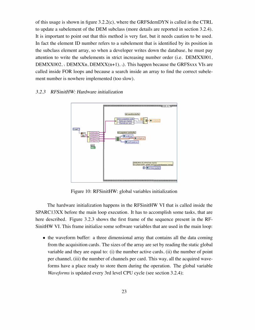
3.2.3 RFSinitHW: Hardware initialization
Figure 10: RFSinitHW: global variables initialization
The hardware initialization happens in the RFSinitHW VI that is called inside theSPARC13XX before the main loop execution. It has to accomplish some tasks, that arehere described. Figure 3.2.3 shows the first frame of the sequence present in the RF-SinitHW VI. This frame initialize some software variables that are used in the main loop:
• the waveform buffer: a three dimensional array that contains all the data comingfrom the acquisition cards. The sizes of the array are set by reading the static globalvariable and they are equal to: (i) the number active cards, (ii) the number of pointper channel, (iii) the number of channels per card. This way, all the acquired wave-forms have a place ready to store them during the operation. The global variableWaveforms is updated every 3rd level CPU cycle (see section 3.2.4);
23
• the global variables concerning the sampling cards configuration. This variables arearray that contains information about the sampling card ID number, configurationand type. These items are necessary because one needs to have a sorted list of thecards and their configurations, stored in the DEM subelements without a preciseorder.
• the Ctrl loop counter. Simply initialize a counter of the SPARC13XX loop cycles.It is needed because the structure of a SPARC13XX VI must be identical for every3rd level CPU. So also the counting of the executed cycle has to be included in theclass specific VIs that we describe in this section.
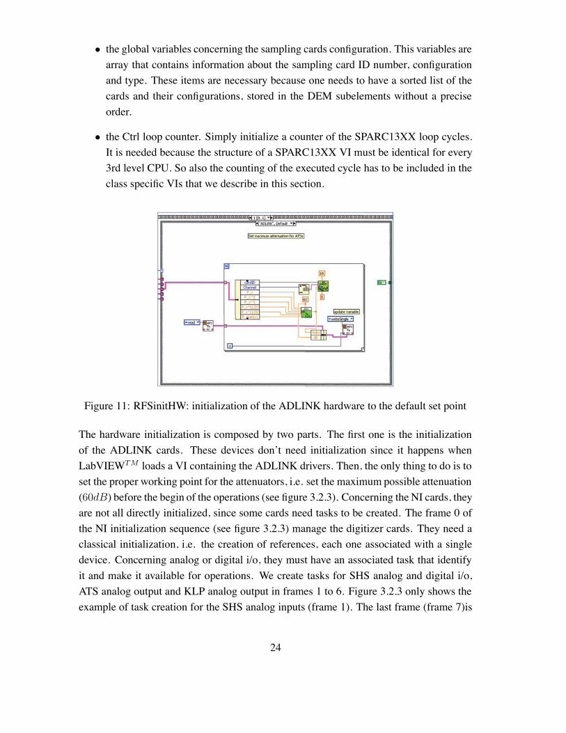
Figure 11: RFSinitHW: initialization of the ADLINK hardware to the default set point
The hardware initialization is composed by two parts. The first one is the initializationof the ADLINK cards. These devices don’t need initialization since it happens whenLabVIEWTM loads a VI containing the ADLINK drivers. Then, the only thing to do is toset the proper working point for the attenuators, i.e. set the maximum possible attenuation(60dB) before the begin of the operations (see figure 3.2.3). Concerning the NI cards, theyare not all directly initialized, since some cards need tasks to be created. The frame 0 ofthe NI initialization sequence (see figure 3.2.3) manage the digitizer cards. They need aclassical initialization, i.e. the creation of references, each one associated with a singledevice. Concerning analog or digital i/o, they must have an associated task that identifyit and make it available for operations. We create tasks for SHS analog and digital i/o,ATS analog output and KLP analog output in frames 1 to 6. Figure 3.2.3 only shows theexample of task creation for the SHS analog inputs (frame 1). The last frame (frame 7)is
24
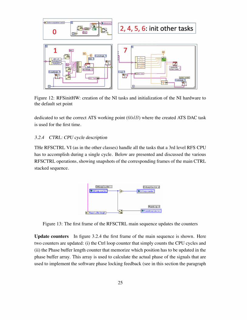
Figure 12: RFSinitHW: creation of the NI tasks and initialization of the NI hardware tothe default set point
dedicated to set the correct ATS working point (60dB) where the created ATS DAC taskis used for the first time.
3.2.4 CTRL: CPU cycle description
THe RFSCTRL VI (as in the other classes) handle all the tasks that a 3rd level RFS CPUhas to accomplish during a single cycle. Below are presented and discussed the variousRFSCTRL operations, showing snapshots of the corresponding frames of the main CTRLstacked sequence.
Figure 13: The first frame of the RFSCTRL main sequence updates the counters
Update counters In figure 3.2.4 the first frame of the main sequence is shown. Heretwo counters are updated: (i) the Ctrl loop counter that simply counts the CPU cycles and(ii) the Phase buffer length counter that memorize which position has to be updated in thephase buffer array. This array is used to calculate the actual phase of the signals that areused to implement the software phase locking feedback (see in this section the paragraph
25
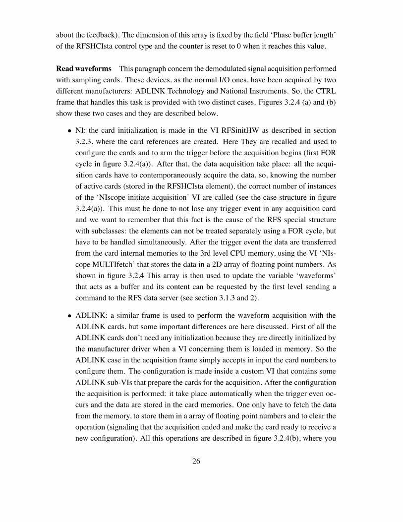
about the feedback). The dimension of this array is fixed by the field ‘Phase buffer length’of the RFSHCIsta control type and the counter is reset to 0 when it reaches this value.
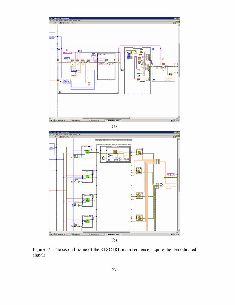
Read waveforms This paragraph concern the demodulated signal acquisition performedwith sampling cards. These devices, as the normal I/O ones, have been acquired by twodifferent manufacturers: ADLINK Technology and National Instruments. So, the CTRLframe that handles this task is provided with two distinct cases. Figures 3.2.4 (a) and (b)show these two cases and they are described below.
• NI: the card initialization is made in the VI RFSinitHW as described in section3.2.3, where the card references are created. Here They are recalled and used toconfigure the cards and to arm the trigger before the acquisition begins (first FORcycle in figure 3.2.4(a)). After that, the data acquisition take place: all the acqui-sition cards have to contemporaneously acquire the data, so, knowing the numberof active cards (stored in the RFSHCIsta element), the correct number of instancesof the ‘NIscope initiate acquisition’ VI are called (see the case structure in figure3.2.4(a)). This must be done to not lose any trigger event in any acquisition cardand we want to remember that this fact is the cause of the RFS special structurewith subclasses: the elements can not be treated separately using a FOR cycle, buthave to be handled simultaneously. After the trigger event the data are transferredfrom the card internal memories to the 3rd level CPU memory, using the VI ‘NIs-cope MULTIfetch’ that stores the data in a 2D array of floating point numbers. Asshown in figure 3.2.4 This array is then used to update the variable ‘waveforms’that acts as a buffer and its content can be requested by the first level sending acommand to the RFS data server (see section 3.1.3 and 2).
• ADLINK: a similar frame is used to perform the waveform acquisition with theADLINK cards, but some important differences are here discussed. First of all theADLINK cards don’t need any initialization because they are directly initialized bythe manufacturer driver when a VI concerning them is loaded in memory. So theADLINK case in the acquisition frame simply accepts in input the card numbers toconfigure them. The configuration is made inside a custom VI that contains someADLINK sub-VIs that prepare the cards for the acquisition. After the configurationthe acquisition is performed: it take place automatically when the trigger even oc-curs and the data are stored in the card memories. One only have to fetch the datafrom the memory, to store them in a array of floating point numbers and to clear theoperation (signaling that the acquisition ended and make the card ready to receive anew configuration). All this operations are described in figure 3.2.4(b), where you
26
(a)
(b)
Figure 14: The second frame of the RFSCTRL main sequence acquire the demodulatedsignals
27
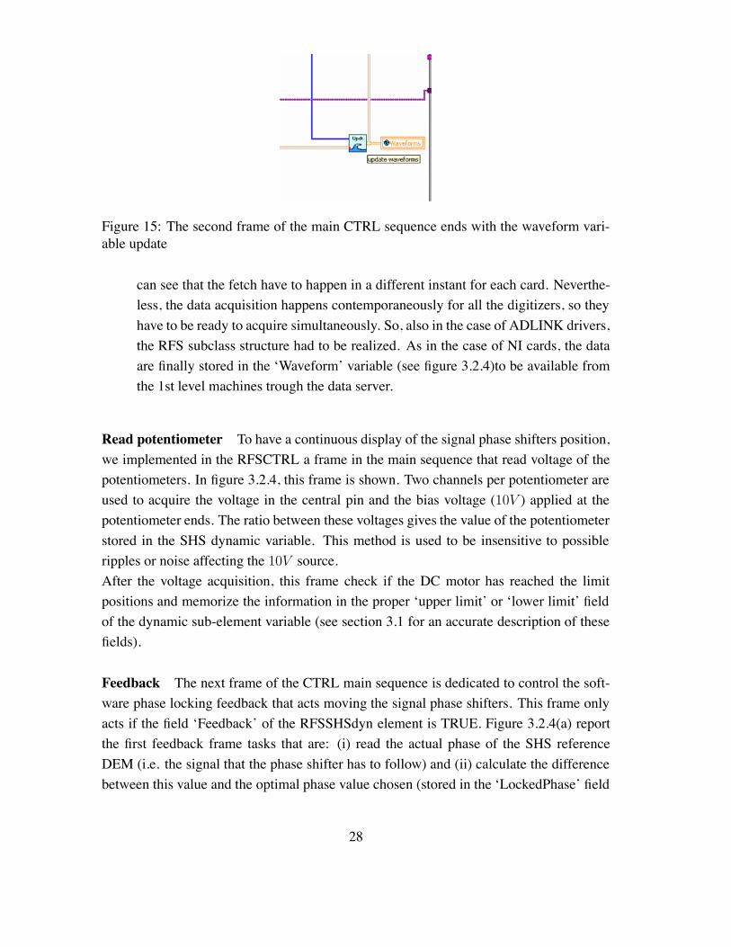
Figure 15: The second frame of the main CTRL sequence ends with the waveform vari-able update
can see that the fetch have to happen in a different instant for each card. Neverthe-less, the data acquisition happens contemporaneously for all the digitizers, so theyhave to be ready to acquire simultaneously. So, also in the case of ADLINK drivers,the RFS subclass structure had to be realized. As in the case of NI cards, the dataare finally stored in the ‘Waveform’ variable (see figure 3.2.4)to be available fromthe 1st level machines trough the data server.
Read potentiometer To have a continuous display of the signal phase shifters position,we implemented in the RFSCTRL a frame in the main sequence that read voltage of thepotentiometers. In figure 3.2.4, this frame is shown. Two channels per potentiometer areused to acquire the voltage in the central pin and the bias voltage (10V ) applied at thepotentiometer ends. The ratio between these voltages gives the value of the potentiometerstored in the SHS dynamic variable. This method is used to be insensitive to possibleripples or noise affecting the 10V source.After the voltage acquisition, this frame check if the DC motor has reached the limitpositions and memorize the information in the proper ‘upper limit’ or ‘lower limit’ fieldof the dynamic sub-element variable (see section 3.1 for an accurate description of thesefields).
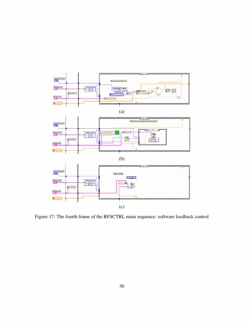
Feedback The next frame of the CTRL main sequence is dedicated to control the soft-ware phase locking feedback that acts moving the signal phase shifters. This frame onlyacts if the field ‘Feedback’ of the RFSSHSdyn element is TRUE. Figure 3.2.4(a) reportthe first feedback frame tasks that are: (i) read the actual phase of the SHS referenceDEM (i.e. the signal that the phase shifter has to follow) and (ii) calculate the differencebetween this value and the optimal phase value chosen (stored in the ‘LockedPhase’ field
28
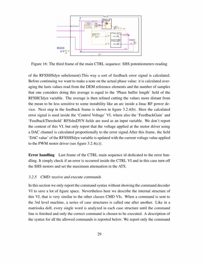
Figure 16: The third frame of the main CTRL sequence: SHS potentiometers reading
of the RFSSHSdyn subelement).This way a sort of feedback error signal is calculated.Before continuing we want to make a note on the actual phase value: it is calculated aver-aging the lasts values read from the DEM reference elements and the number of samplesthat one considers doing this average is equal to the ‘Phase buffer length’ field of theRFSHCIdyn variable. The average is then refined cutting the values more distant fromthe mean to be less sensitive to some instability like an arc inside a linac RF power de-vice. Next step in the feedback frame is shown in figure 3.2.4(b). Here the calculatederror signal is used inside the ‘Control Voltage’ VI, where also the ‘FeedbackGain’ and‘FeedbackThreshold’ RFSshsDYN fields are used as an input variable. We don’t reportthe content of this VI, but only report that the voltage applied at the motor driver usinga DAC channel is calculated proportionally to the error signal.After this frame, the field‘DAC value’ of the RFSSHSdyn variable is updated with the current voltage value appliedto the PWM motor driver (see figure 3.2.4(c)).
Error handling Last frame of the CTRL main sequence id dedicated to the error han-dling. It simply check if an error is occurred inside the CTRL VI and in this case turn offthe SHS motors and set the maximum attenuation in the ATS.
3.2.5 CMD: receive and execute commands
In this section we only report the command syntax without showing the command decoderVI to save a lot of figure space. Nevertheless here we describe the internal structure ofthis VI, that is very similar to the other classes CMD VIs. When a command is sent tothe 3rd level machine, a series of case structures is called one after another. Like in amatrioska doll, every single word is analyzed in each case structure until the commandline is finished and only the correct command is chosen to be executed. A description ofthe syntax for all the allowed commands is reported below. We report only the command
29
(a)
(b)
(c)
Figure 17: The fourth frame of the RFSCTRL main sequence: software feedback control
30
parameters that are placed after the class element name (in this case RFSXX00n) and afterthe command descriptor (SETT, SWTC, etc.) in the command line sent from the consolelevel.
SETT decoder This VI is called if the command identifier in the command line sentfrom the console level is ‘SETT’. Here we report the command parameters and theirmeaning, i.e. the physical action that the 3rd level CPU perform after receiving it.
• DEMXXnnn topstart n (integer number): sets in the RFSDEMdyn variable the av-erage beginning position, expressed in sampling points, to calculate the top valueof a square pulse;
• DEMXXnnn toplength n (integer number): sets in the RFSDEMdyn variable thenumber sampling points used to calculate the top value of a square pulse;
• DEMXXnnn botstart n (integer number): sets in the RFSDEMdyn variable the aver-age beginning position, expressed in sampling points, to calculate the bottom value(when RF is OFF) of a demodulated pulse;
• DEMXXnnn botlength n (integer number): sets in the RFSDEMdyn variable thenumber sampling points used to calculate the bottom value of an RF pulse;
• DEMXXnnn fitstart n (integer number): sets in the RFSDEMdyn variable the fit be-ginning position, expressed in sampling points, to calculate the phase or amplitudevalue of an exponential decaying pulse;
• DEMXXnnn lnfitlen n (integer number): sets in the RFSDEMdyn variable the num-ber sampling points used to calculate the phase value of an exponential decayingpulse;
• DEMXXnnn exfitlen n (integer number): sets in the RFSDEMdyn variable thenumber sampling points used to calculate the amplitude value of an exponentialdecaying pulse;
• SHSXXnnn REV2: sets the maximum reverse speed for a signal phase shifter motor(0V at the input of the PWM motor driver) and updates the RFSSHSdyn variable;
• SHSXXnnn REV2: sets the medium reverse speed for a signal phase shifter motor(1.5V at the input of the PWMmotor driver) and updates the RFSSHSdyn variable;
• SHSXXnnn STOP: stops a signal phase shifter motor (2V at the input of the PWMmotor driver) and updates the RFSSHSdyn variable;
31
• SHSXXnnn FRW1: sets the medium forward speed for a signal phase shifter motor(2.5V at the input of the PWMmotor driver) and updates the RFSSHSdyn variable;
• SHSXXnnn FRW2: sets the maximum forward speed for a signal phase shiftermotor (4V at the input of the PWM motor driver) and updates the RFSSHSdynvariable;
• SHSXXnnn PHAS n (floating point number): sets the phase that the software feed-back follow and stores this value in the RFSSHSdyn variable;
• SHSXXnnn GAIN n(floating point number): this command sets the feedback gainfor an SHS device changing the ‘FeedbackGain’ field inside the RFSshsDYN vari-able. See section 3.1 for further details;
• SHSXXnnn TRSH n(floating point number): this command sets the feedback thresh-old for an SHS device changing the ‘FeedbackThreshold’ field inside the RFSshs-DYN variable. The threshold is the minimum phase difference for the feedbackintervention. See section 3.1 for further details;
• SHSXXnnn BUFF n(integer number): this command sets the phase buffer lengthfor the SHS devices changing the ‘Phase buffer length’ field inside the RFShciDYNvariable. Pay attention using this command because it affect ALL the phase shifterdevices at the same time (also if the command is called with a single device name).See section 3.1 for further details;
• ATSXXnnn dB n (floating point number): sets the chosen attenuation to a signalattenuator and updates the RFSATSdyn variable with the output voltage value andthe corresponding attenuation value (expressed in dB);
• KLPXXnnn PHI: sets the fast klystron phase feedback working point acting on anelectronic phase shifter voltage input and updates the RFSKLPdyn variable;
• KLPXXnnn REF: sets the fast klystron phase feedback amplifiers reference voltageand updates the RFSKLPdyn variable.
READ decoder This VI is called if the command identifier in the command line sentfrom the console level is ‘READ’. Here we report the command parameters and theirmeaning, i.e. the physical action that the 3rd level CPU perform after receiving it.
32
• SHSXXnnn POT: reads a signal phase sifter potentiometer voltage (doing a ratiobetween the central pin voltage and the bias voltage) and updates the RFSSHSdynvariable corresponding field.
SWTC decoder This VI is called if the command identifier in the command line sentfrom the console level is ‘SWTC’. Here we report the command parameters and theirmeaning, i.e. the physical action that the 3rd level CPU perform after receiving it.
• SHSXXnnn ON: switches a signal phase shifter PWM motor driver ON using adigital output and updates the RFSSHSdyn variable;
• SHSXXnnn OFF: switches a signal phase shifter PWM motor driver OFF using adigital output and updates the RFSSHSdyn variable;
• SHSXXnnn FDBON: switches a signal phase shifter software feedback ON, initial-izes the ‘PhaseLoop’ buffer with the actual measured phase at the reference DEMelement and updates the RFSSHSdyn variable;
• SHSXXnnn FDB OFF: switches a signal phase shifter software feedback OFF andupdates the RFSSHSdyn variable.
3.2.6 RFS close hardware
Also in this case we chose to not report images of this VI, because its functioning is veryintuitive and there are a lot of frames that don’t need a graphical explication. In fact theRFScloseHWVI check whether NI or ADLINK cards are used and perform the followingactions:
• it sets the maximum attenuation in the ATS elements;
• it stops and turns off the SHS motors;
• in the case of NI hardware it also closes all the opened ADC, DAC and DIO tasksand the sampling card references.
Here we want to remember that the ADLINK cards don’t need to be initialized and re-leased because their driver automatically do it when a pertinent VI is open or when aLabVIEWTM instance is closed.
33
3.3 1st level VIs: a manual both for the developer and operators
The aim of this section is to describe the main RFS class related control panels (1st levelVIs), that any operator can open using a control room console. These VIs are able to sendcommands to the CPUs simply pressing a button. This way the machine control becomevery simple and all the tasks can be performed by an operator that does not know thecontrol system architecture.
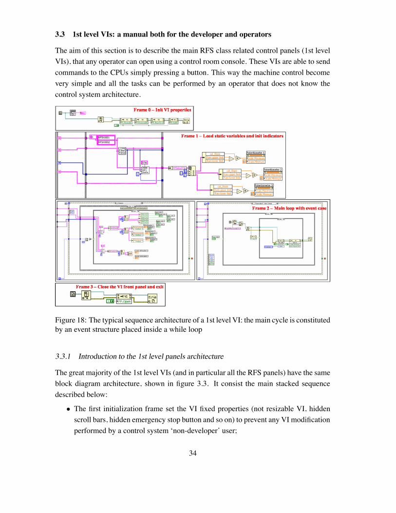
Figure 18: The typical sequence architecture of a 1st level VI: the main cycle is constitutedby an event structure placed inside a while loop
3.3.1 Introduction to the 1st level panels architecture
The great majority of the 1st level VIs (and in particular all the RFS panels) have the sameblock diagram architecture, shown in figure 3.3. It consist the main stacked sequencedescribed below:
• The first initialization frame set the VI fixed properties (not resizable VI, hiddenscroll bars, hidden emergency stop button and so on) to prevent any VI modificationperformed by a control system ‘non-developer’ user;
34
• The second frame is another frame of initialization, where the needed STA variablesare loaded from the 3rd level CPUs and some properties of the front panel indicatorsare set;
• The third frame contains the main while loop that remains active until the VI isclosed. Inside this while loop a event structure is placed. An event can be related tomouse moves or clicks or to other software trigger that one can choose from a list.This kind of structure has a mandatory ‘Timeout’ frame that waits for ‘events’ a setamount of time and then execute its content. In practice here the developer puts thecommands and tasks executed every while cycle. The other frames are identified byan event and are executed only if this event occurs before the timeout. The devel-oper will create a number of event frames equal to the number of commands the VIcan send to the 3rd level CPUs. In fact the panel is normally designed inserting but-tons, knobs and other GUI objects and linking a mouse action performed on themto an event frame. So if no mouse action is performed the VI continue to executeonly the ‘Timeout’ frame (that is normally used to display some DYN variable fieldvalues); else, if an operator wants to execute a command, for example pressing abutton, the related event frame is executed (normally it sends a command to the 3rdlevel or modifies an information display property);
• Finally, when the while cycle is stopped (using a special custom button), the lastframe of the main sequence is executed. It closes the front panel, protecting the VIfrom further modifications.
In the following sections we will precisely describe the aspect and functioning of all the1st level VI front panels that control the RFS class objects.
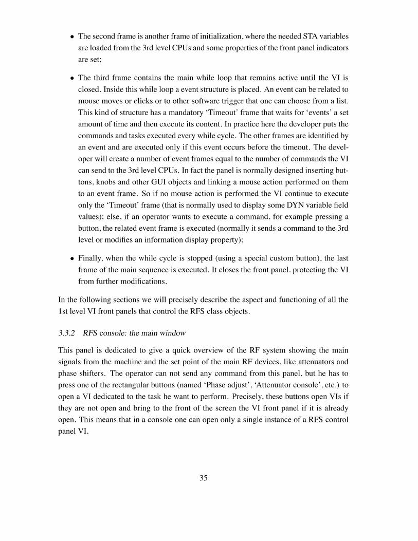
3.3.2 RFS console: the main window
This panel is dedicated to give a quick overview of the RF system showing the mainsignals from the machine and the set point of the main RF devices, like attenuators andphase shifters. The operator can not send any command from this panel, but he has topress one of the rectangular buttons (named ‘Phase adjust’, ‘Attenuator console’, etc.) toopen a VI dedicated to the task he want to perform. Precisely, these buttons open VIs ifthey are not open and bring to the front of the screen the VI front panel if it is alreadyopen. This means that in a console one can open only a single instance of a RFS controlpanel VI.
35
Figure 19: The front panel of the RFSconsole VI, the main control panel of the RFSsystem
3.3.3 RFS console: Waveform monitor
This is the most simple panel to use for an operator, because it only shows the signalscoming from the RF devices along the machine. The only actions allowed are: (i) pressthe button above each graph to choose the location of the signal to display and (ii) pressthe ‘print’ button opening the SPARC logbook prompt to insert data and graphs into it.The waveforms displayed are white or red. The white waveform represents the amplitudeof the signal while the red one represents the phase of the signal. Note that not all thesignals have the red graph active because some of them are obtained from a device notable to detect the phase (for example an RF peak detector).
3.3.4 RFS console: Attenuator console
This is another very simple VI that controls the signal attenuators placed before the finalamplification stage that feeds the waveguides with the radiation. The panel is dividedinto two identical regions because there are two low level attenuators, each one before aklystron. To set a random attenuation (from 0dB to 60dB) the operator must write thedesired value in the right numeric control and press the arrow button. After a while, ifno error is occurred, the command is executed and the new set point is shown in the left
36
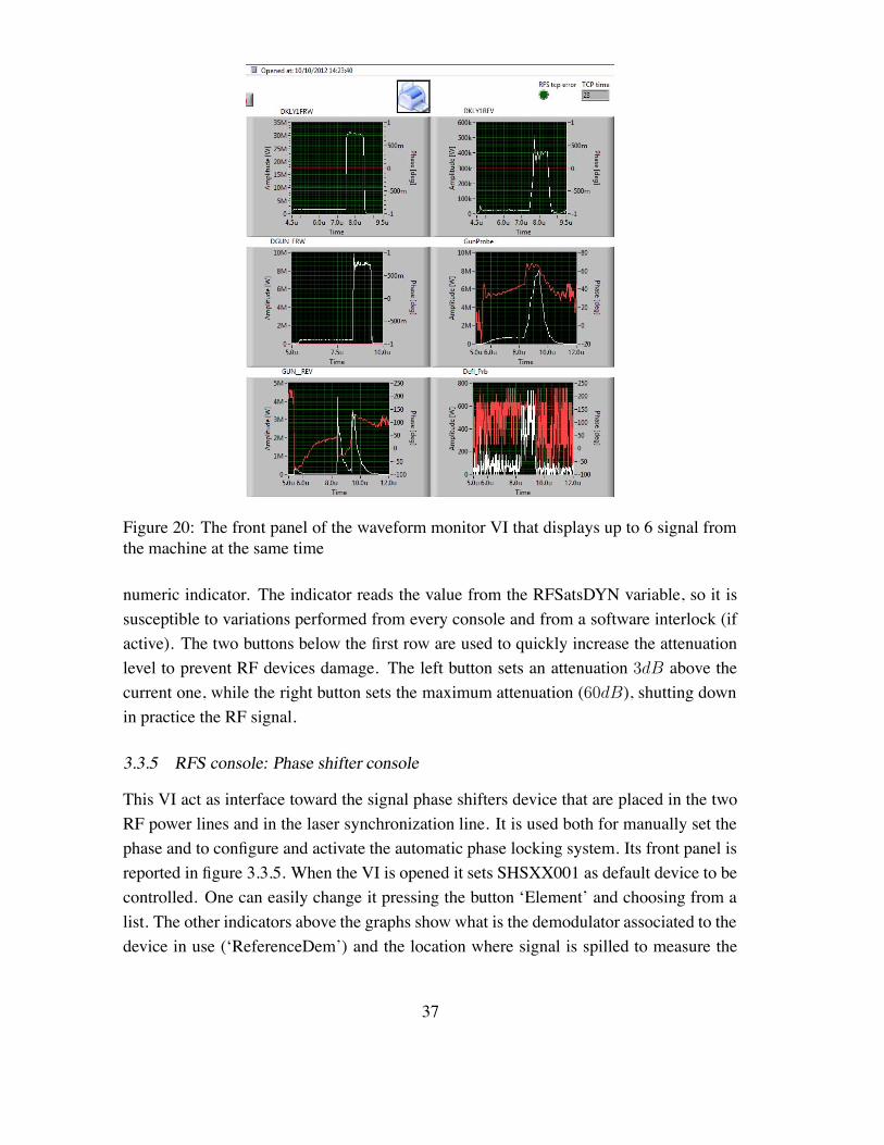
Figure 20: The front panel of the waveform monitor VI that displays up to 6 signal fromthe machine at the same time
numeric indicator. The indicator reads the value from the RFSatsDYN variable, so it issusceptible to variations performed from every console and from a software interlock (ifactive). The two buttons below the first row are used to quickly increase the attenuationlevel to prevent RF devices damage. The left button sets an attenuation 3dB above thecurrent one, while the right button sets the maximum attenuation (60dB), shutting downin practice the RF signal.
3.3.5 RFS console: Phase shifter console
This VI act as interface toward the signal phase shifters device that are placed in the twoRF power lines and in the laser synchronization line. It is used both for manually set thephase and to configure and activate the automatic phase locking system. Its front panel isreported in figure 3.3.5. When the VI is opened it sets SHSXX001 as default device to becontrolled. One can easily change it pressing the button ‘Element’ and choosing from alist. The other indicators above the graphs show what is the demodulator associated to thedevice in use (‘ReferenceDem’) and the location where signal is spilled to measure the
37
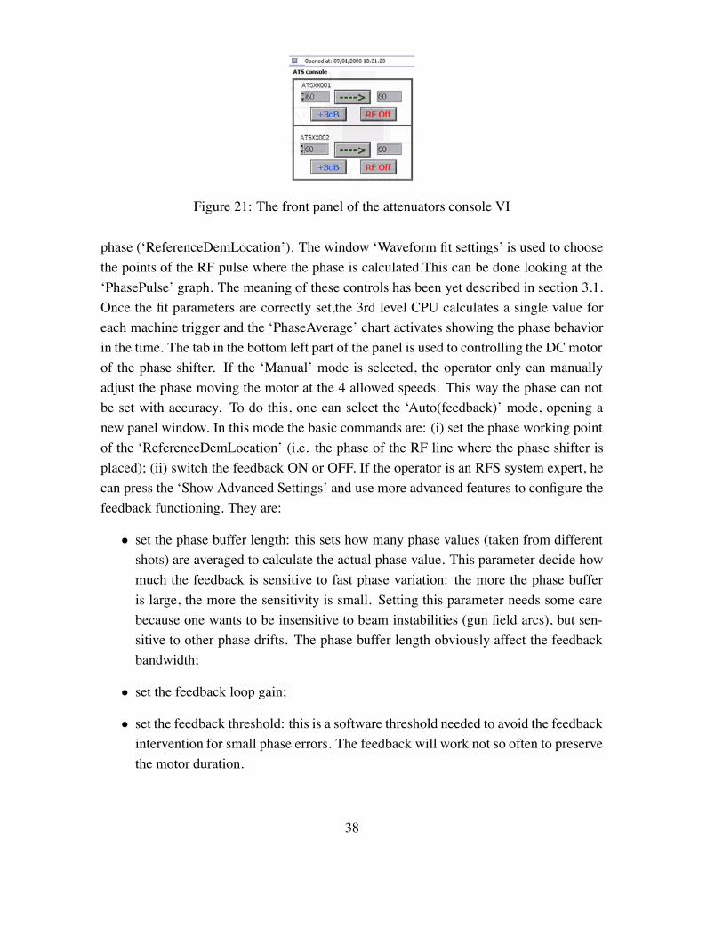
Figure 21: The front panel of the attenuators console VI
phase (‘ReferenceDemLocation’). The window ‘Waveform fit settings’ is used to choosethe points of the RF pulse where the phase is calculated.This can be done looking at the‘PhasePulse’ graph. The meaning of these controls has been yet described in section 3.1.Once the fit parameters are correctly set,the 3rd level CPU calculates a single value foreach machine trigger and the ‘PhaseAverage’ chart activates showing the phase behaviorin the time. The tab in the bottom left part of the panel is used to controlling the DC motorof the phase shifter. If the ‘Manual’ mode is selected, the operator only can manuallyadjust the phase moving the motor at the 4 allowed speeds. This way the phase can notbe set with accuracy. To do this, one can select the ‘Auto(feedback)’ mode, opening anew panel window. In this mode the basic commands are: (i) set the phase working pointof the ‘ReferenceDemLocation’ (i.e. the phase of the RF line where the phase shifter isplaced); (ii) switch the feedback ON or OFF. If the operator is an RFS system expert, hecan press the ‘Show Advanced Settings’ and use more advanced features to configure thefeedback functioning. They are:
• set the phase buffer length: this sets how many phase values (taken from differentshots) are averaged to calculate the actual phase value. This parameter decide howmuch the feedback is sensitive to fast phase variation: the more the phase bufferis large, the more the sensitivity is small. Setting this parameter needs some carebecause one wants to be insensitive to beam instabilities (gun field arcs), but sen-sitive to other phase drifts. The phase buffer length obviously affect the feedbackbandwidth;
• set the feedback loop gain;
• set the feedback threshold: this is a software threshold needed to avoid the feedbackintervention for small phase errors. The feedback will work not so often to preservethe motor duration.
38
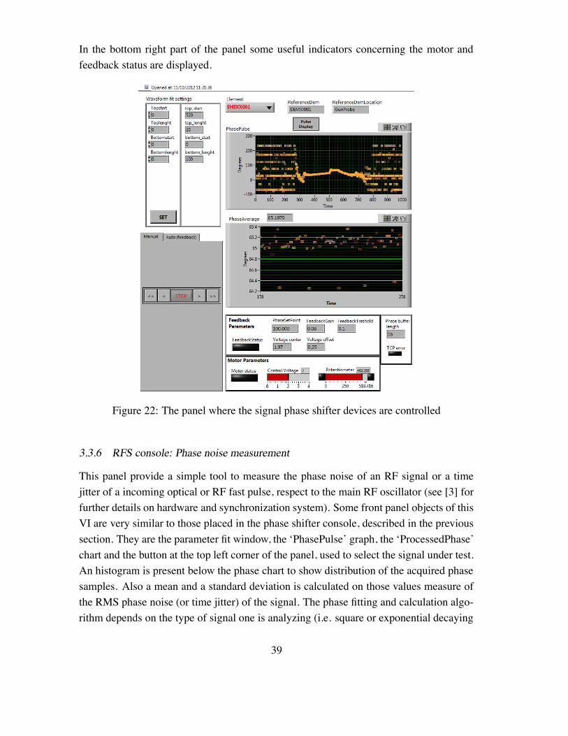
In the bottom right part of the panel some useful indicators concerning the motor andfeedback status are displayed.
Figure 22: The panel where the signal phase shifter devices are controlled
3.3.6 RFS console: Phase noise measurement
This panel provide a simple tool to measure the phase noise of an RF signal or a timejitter of a incoming optical or RF fast pulse, respect to the main RF oscillator (see [3] forfurther details on hardware and synchronization system). Some front panel objects of thisVI are very similar to those placed in the phase shifter console, described in the previoussection. They are the parameter fit window, the ‘PhasePulse’ graph, the ‘ProcessedPhase’chart and the button at the top left corner of the panel, used to select the signal under test.An histogram is present below the phase chart to show distribution of the acquired phasesamples. Also a mean and a standard deviation is calculated on those values measure ofthe RMS phase noise (or time jitter) of the signal. The phase fitting and calculation algo-rithm depends on the type of signal one is analyzing (i.e. square or exponential decaying
39
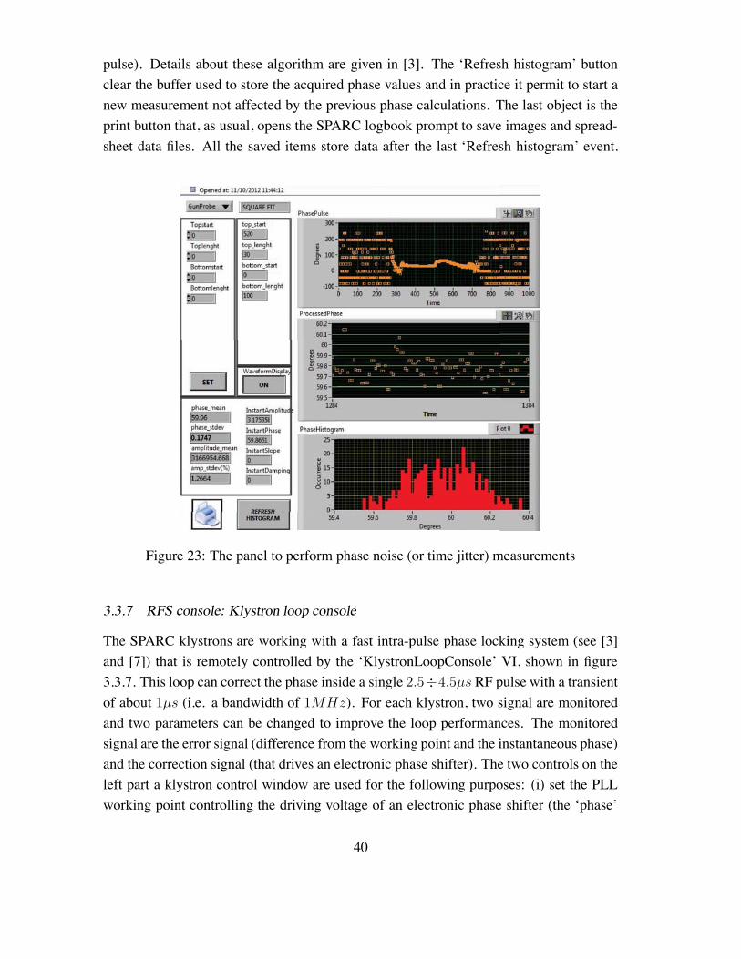
pulse). Details about these algorithm are given in [3]. The ‘Refresh histogram’ buttonclear the buffer used to store the acquired phase values and in practice it permit to start anew measurement not affected by the previous phase calculations. The last object is theprint button that, as usual, opens the SPARC logbook prompt to save images and spread-sheet data files. All the saved items store data after the last ‘Refresh histogram’ event.
Figure 23: The panel to perform phase noise (or time jitter) measurements
3.3.7 RFS console: Klystron loop console
The SPARC klystrons are working with a fast intra-pulse phase locking system (see [3]and [7]) that is remotely controlled by the ‘KlystronLoopConsole’ VI, shown in figure3.3.7. This loop can correct the phase inside a single 2.5÷4.5µs RF pulse with a transientof about 1µs (i.e. a bandwidth of 1MHz). For each klystron, two signal are monitoredand two parameters can be changed to improve the loop performances. The monitoredsignal are the error signal (difference from the working point and the instantaneous phase)and the correction signal (that drives an electronic phase shifter). The two controls on theleft part a klystron control window are used for the following purposes: (i) set the PLLworking point controlling the driving voltage of an electronic phase shifter (the ‘phase’
40
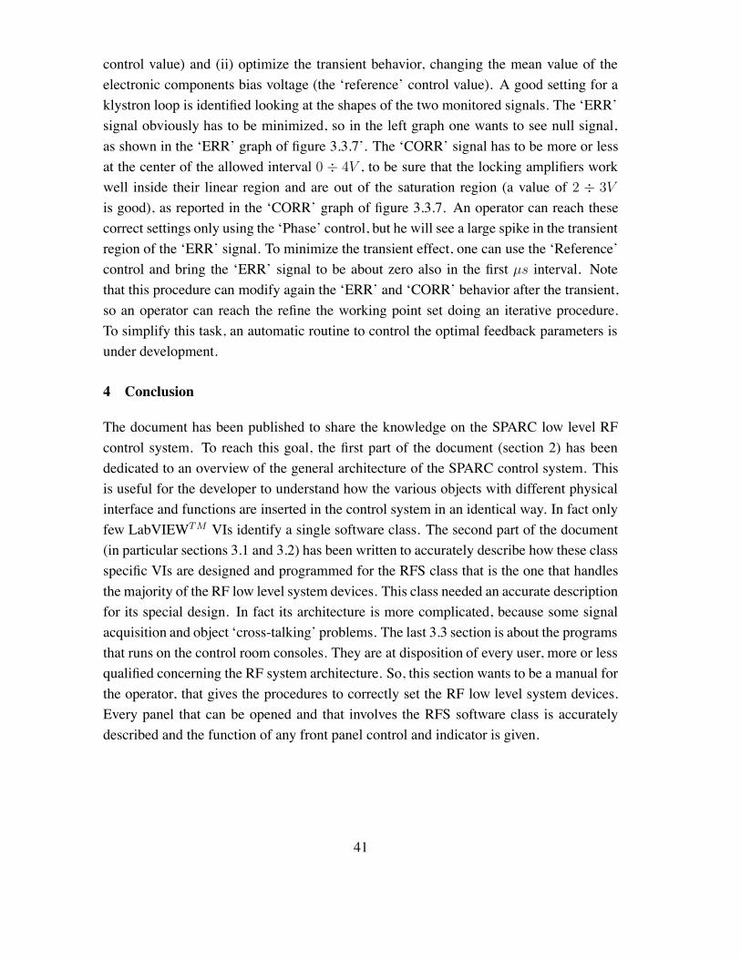
control value) and (ii) optimize the transient behavior, changing the mean value of theelectronic components bias voltage (the ‘reference’ control value). A good setting for aklystron loop is identified looking at the shapes of the two monitored signals. The ‘ERR’signal obviously has to be minimized, so in the left graph one wants to see null signal,as shown in the ‘ERR’ graph of figure 3.3.7’. The ‘CORR’ signal has to be more or lessat the center of the allowed interval 0 ÷ 4V , to be sure that the locking amplifiers workwell inside their linear region and are out of the saturation region (a value of 2 ÷ 3V
is good), as reported in the ‘CORR’ graph of figure 3.3.7. An operator can reach thesecorrect settings only using the ‘Phase’ control, but he will see a large spike in the transientregion of the ‘ERR’ signal. To minimize the transient effect, one can use the ‘Reference’control and bring the ‘ERR’ signal to be about zero also in the first µs interval. Notethat this procedure can modify again the ‘ERR’ and ‘CORR’ behavior after the transient,so an operator can reach the refine the working point set doing an iterative procedure.To simplify this task, an automatic routine to control the optimal feedback parameters isunder development.
4 Conclusion
The document has been published to share the knowledge on the SPARC low level RFcontrol system. To reach this goal, the first part of the document (section 2) has beendedicated to an overview of the general architecture of the SPARC control system. Thisis useful for the developer to understand how the various objects with different physicalinterface and functions are inserted in the control system in an identical way. In fact onlyfew LabVIEWTM VIs identify a single software class. The second part of the document(in particular sections 3.1 and 3.2) has been written to accurately describe how these classspecific VIs are designed and programmed for the RFS class that is the one that handlesthe majority of the RF low level system devices. This class needed an accurate descriptionfor its special design. In fact its architecture is more complicated, because some signalacquisition and object ‘cross-talking’ problems. The last 3.3 section is about the programsthat runs on the control room consoles. They are at disposition of every user, more or lessqualified concerning the RF system architecture. So, this section wants to be a manual forthe operator, that gives the procedures to correctly set the RF low level system devices.Every panel that can be opened and that involves the RFS software class is accuratelydescribed and the function of any front panel control and indicator is given.
41
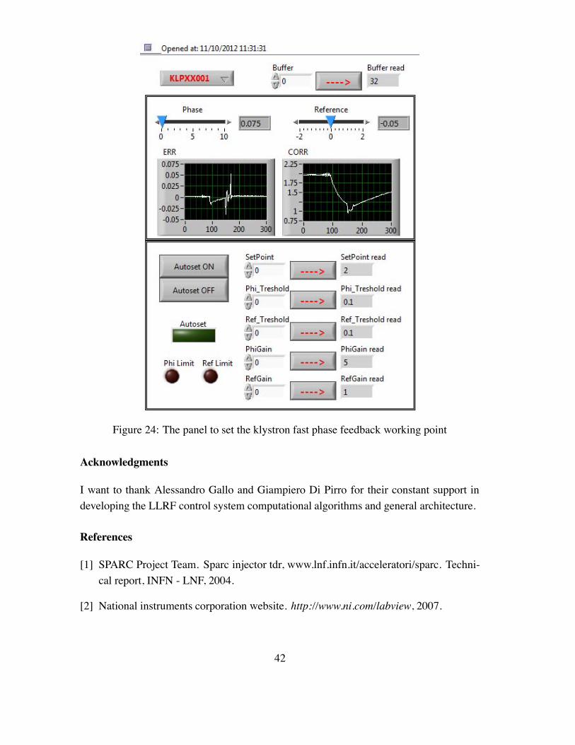
Figure 24: The panel to set the klystron fast phase feedback working point
Acknowledgments
I want to thank Alessandro Gallo and Giampiero Di Pirro for their constant support indeveloping the LLRF control system computational algorithms and general architecture.
References
[1] SPARC Project Team. Sparc injector tdr, www.lnf.infn.it/acceleratori/sparc. Techni-cal report, INFN - LNF, 2004.
[2] National instruments corporation website. http://www.ni.com/labview, 2007.
42
[3] M. Bellaveglia. Radio frequency control system and synchronization in high bright-ness photo-injectors driving FEL experiments. PhD thesis, Unversita’ degli studi diRoma ‘La Sapienza’, 2006.
[4] M. Bellaveglia et al. First operation with sparc control system. Proc. of PcaPAC2006,CEBAF Center Jefferson Lab Newport News, VA USA, Oct. 2006.
[5] G. Di Pirro et al. Dante: Control system for dafne based on macintosh and labview.Nuclear Instrument and Methods in Physics Research A 352 455-475, 1994.
[6] L. Catani. A communication protocol for a distributed control system with labview.Proc. of PcaPAC2006, CEBAF Center Jefferson Lab Newport News, VA USA, Oct.2006.
[7] G. Gatti C. Vicario A. Gallo, M. Bellaveglia. Laser and rf synchronization measure-ments at sparc. Proceedings of PAC07, Albuquerque, New Mexico, USA, 2007.
43
Contents
1 Introduction 2
2 The SPARC control system 22.1 Overview . . . . . . . . . . . . . . . . . . . . . . . . . . . . . . . . . . 22.2 Software . . . . . . . . . . . . . . . . . . . . . . . . . . . . . . . . . . . 32.3 The SPARC network . . . . . . . . . . . . . . . . . . . . . . . . . . . . 42.4 System architecture . . . . . . . . . . . . . . . . . . . . . . . . . . . . . 4
2.4.1 Database . . . . . . . . . . . . . . . . . . . . . . . . . . . . . . 62.4.2 The front-end (or 3rd) level . . . . . . . . . . . . . . . . . . . . 72.4.3 The intermediate (or 2nd) level . . . . . . . . . . . . . . . . . . . 82.4.4 The console (or 1st) level . . . . . . . . . . . . . . . . . . . . . . 9
3 The low level RF control system 103.1 Virtual world and real world . . . . . . . . . . . . . . . . . . . . . . . . 10
3.1.1 RFS: the main class . . . . . . . . . . . . . . . . . . . . . . . . . 103.1.2 Subclasses . . . . . . . . . . . . . . . . . . . . . . . . . . . . . 143.1.3 RFS data types . . . . . . . . . . . . . . . . . . . . . . . . . . . 21
3.2 The 3rd level VIs: a manual for the developer . . . . . . . . . . . . . . . 213.2.1 Overview and actual hardware arrangement . . . . . . . . . . . . 213.2.2 RFSLoadRTDB, GRFSsta and GRFSdyn: loading the database
and handling global variables . . . . . . . . . . . . . . . . . . . 223.2.3 RFSinitHW: Hardware initialization . . . . . . . . . . . . . . . . 233.2.4 CTRL: CPU cycle description . . . . . . . . . . . . . . . . . . . 253.2.5 CMD: receive and execute commands . . . . . . . . . . . . . . . 293.2.6 RFS close hardware . . . . . . . . . . . . . . . . . . . . . . . . 33
3.3 1st level VIs: a manual both for the developer and operators . . . . . . . 343.3.1 Introduction to the 1st level panels architecture . . . . . . . . . . 343.3.2 RFS console: the main window . . . . . . . . . . . . . . . . . . 353.3.3 RFS console: Waveform monitor . . . . . . . . . . . . . . . . . 363.3.4 RFS console: Attenuator console . . . . . . . . . . . . . . . . . 363.3.5 RFS console: Phase shifter console . . . . . . . . . . . . . . . . 373.3.6 RFS console: Phase noise measurement . . . . . . . . . . . . . . 393.3.7 RFS console: Klystron loop console . . . . . . . . . . . . . . . . 40
4 Conclusion 41
44