Embed Size (px)
Citation preview
sensors
Article
Custom-Fitted In- and Around-the-Ear Sensors for Unobtrusiveand On-the-Go EEG Acquisitions: Development and Validation
Olivier Valentin 1,2,* , Guilhem Viallet 1, Aidin Delnavaz 1 , Gabrielle Cretot-Richert 1,2, Mikaël Ducharme 1,Hami Monsarat-Chanon 1 and Jérémie Voix 1,2
Citation: Valentin, O.; Viallet, G.;
Delnavaz, A.; Cretot-Richert, G.;
Ducharme, M.; Monsarat-Chanon, H.;
Voix, J. Custom-Fitted In- and
Around-the-Ear Sensors for
Unobtrusive and On-the-Go EEG
Acquisitions: Development and
Validation. Sensors 2021, 21, 2953.
https://doi.org/10.3390/s21092953
Academic Editor: James Rusling
Received: 6 March 2021
Accepted: 18 April 2021
Published: 23 April 2021
Publisher’s Note: MDPI stays neutral
with regard to jurisdictional claims in
published maps and institutional affil-
iations.
Copyright: © 2021 by the authors.
Licensee MDPI, Basel, Switzerland.
This article is an open access article
distributed under the terms and
conditions of the Creative Commons
Attribution (CC BY) license (https://
creativecommons.org/licenses/by/
4.0/).
1 École de Technologie Supérieure, 1100 Rue Notre-Dame Ouest, Montréal, QC H3C 1K3, Canada;[email protected] (G.V.); [email protected] (A.D.); [email protected] (G.C.-R.);[email protected] (M.D.); [email protected] (H.M.-C.); [email protected] (J.V.)
2 Centre for Interdisciplinary Research in Music, Media, and Technology, McGill University, 527 RueSherbrooke Ouest, Montréal, QC H3A 1E3, Canada
* Correspondence: [email protected]
Abstract: Objectives: This paper aims to validate the performance and physical design of a wearable,unobtrusive ear-centered electroencephalography (EEG) device, dubbed “EARtrodes”, using earlyand late auditory evoked responses. Results would also offer a proof-of-concept for the deviceto be used as a concealed brain–computer interface (BCI). Design: The device is composed of acustom-fitted earpiece and an ergonomic behind-the-ear piece with embedded electrodes made of asoft and flexible combination of silicone rubber and carbon fibers. The location of the conductivesilicone electrodes inside the ear canal and the optimal geometry of the behind-the-ear piece wereobtained through morphological and geometrical analysis of the human ear canal and the regionaround-the-ear. An entirely conductive generic earpiece was also developed to assess the potential ofa universal, more affordable solution. Results: Early latency results illustrate the conductive siliconeelectrodes’ capability to record quality EEG signals, comparable to those obtained with traditionalgold-plated electrodes. Additionally, late latency results demonstrate EARtrodes’ capacity to reliablydetect decision-making processes from the ear. Conclusions: EEG results validate the performanceof EARtrodes as a circum-aural and intra-aural EEG recording system adapted for a wide range ofapplications in audiology, neuroscience, clinical research, and as an unobtrusive BCI.
Keywords: silicone electrodes; wearables; brain computer interface (BCI); auditory steady-stateresponse (ASSR); event-related potentials (ERP); electroencephalography (EEG)
1. Introduction
Electroencephalography (EEG) is a valuable tool for understanding brain function.It has been widely used for medical diagnoses, neurocognitive research and brain–computerinterfaces (BCI) [1]. Conventional EEG systems measure the brain’s electrical activity usingcaps, which maintain electrodes in contact with the skull (scalp-EEG) and which are con-nected to wires transmitting the signals to differential amplifiers connected to a computer.State-of-the-art EEG recording requires trained clinicians, long preparation times of theskin surface to reduce skin–electrode electrical impedance, and a high-level laboratoryinfrastructure to provide controlled environments. In addition, wired EEG technologyheavily restricts user mobility since any cable movements can greatly compromise signalquality. Moreover, EEG caps are uncomfortable to wear, impractical for daily-life situa-tions and inadequate for social settings. These restrictions limit the research questionsthat can be addressed with conventional EEG and prevent its extensive potential for BCIapplications [2].
The proposed ear-EEG acquisition system including intra-aural (inside the ear canal)and circum-aural (around the ear canal) EEG is a relatively new approach with user-friendly characteristics [3]. This approach can bring EEG into the consumer domain and
Sensors 2021, 21, 2953. https://doi.org/10.3390/s21092953 https://www.mdpi.com/journal/sensors
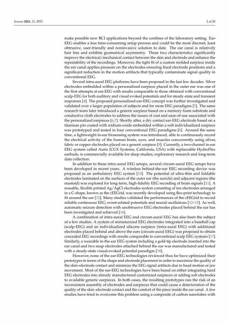
Sensors 2021, 21, 2953 2 of 20
make possible new BCI applications beyond the confines of the laboratory setting. Ear-EEG enables a less time-consuming setup process and could be the most discreet, leastobtrusive, user-friendly and noninvasive solution to date. The ear canal is relativelyhair free and exhibits geometrical asymmetry. These two characteristics significantlyimprove the electrical/mechanical contact between the skin and electrode and enhance therepeatability of the recordings. Moreover, the tight fit of a custom molded earpiece insidethe ear canal applies pressure on the electrodes ensuring fixed electrode positions and asignificant reduction in the motion artifacts that typically contaminate signal quality inconventional EEG.
Several intra-aural EEG platforms have been proposed in the last few decades. Silverelectrodes embedded within a personalized earpiece placed in the outer ear was one ofthe first attempts at ear-EEG with results comparable to those obtained with conventionalscalp-EEG for both auditory and visual evoked potentials and for steady-state and transientresponses [4]. The proposed personalized ear-EEG concept was further investigated andvalidated over a larger population of subjects and for more EEG paradigms [5]. The sameresearch team later introduced a generic earpiece based on a memory foam substrate andconductive cloth electrodes to address the issues of cost and ease-of-use associated withthe personalized earpieces [6,7]. Shortly after, a dry contact ear-EEG electrode based on atitanium pin coated with iridium-oxide embedded within a soft individualized earpiecewas prototyped and tested in four conventional EEG paradigms [8]. Around the sametime, a lightweight in-ear biosensing system was introduced, able to continuously recordthe electrical activity of the human brain, eyes, and muscles concurrently using silver,fabric or copper electrodes placed on a generic earpiece [9]. Currently, a two-channel in-earEEG system called Auris (CGX Systems, California, USA) with replaceable HydroFlexearbuds, is commercially available for sleep studies, exploratory research and long-termdata collection.
In addition to these intra-aural EEG setups, several circum-aural EEG setups havebeen developed in recent years. A wireless behind-the-ear EEG recording device wasproposed as an ambulatory EEG system [10]. The potential of ultra-thin and foldableelectrodes laminated on the surfaces of the outer ear (the auricle) and adjacent regions (themastoid) was explored for long-term, high-fidelity EEG recording of brain signals [11]. Areusable, flexible printed Ag/AgCl electrodes system consisting of ten electrodes arrangedin a C-shape, known as the cEEGrid, was recently developed using flex-print technology tofit around the ear [12]. Many studies validated the performances of the cEEGrid to recordreliable continuous EEG, event-related potentials and neural oscillations [12–15]. As well,automatic seizure detection with unobtrusive EEG electrodes placed behind the ear hasbeen investigated and achieved [16].
A combination of intra-aural EEG and circum-aural EEG has also been the subjectof a few studies. A system of miniaturized EEG electrodes integrated into a baseball cap(scalp-EEG) and an individualized silicone earpiece (intra-aural EEG) with additionalelectrodes placed behind and above the ears (circum-aural EEG) was proposed to obtainconcealed EEG recordings with results comparable to conventional scalp EEG systems [17].Similarly, a wearable in-the-ear EEG system including a gold-tip electrode inserted into theear canal and two snap electrodes attached behind the ear was manufactured and testedwith a steady-state visual-evoked potential paradigm [18].
However, none of the ear-EEG technologies reviewed thus far have optimized theirprototypes in terms of the shape and electrode placement in order to maximize the quality ofthe skin–electrode contact and minimize the EEG signal artifacts due to head motion or jawmovement. Most of the ear-EEG technologies have been based on either integrating hardEEG electrodes into already manufactured customized earpieces or adding soft electrodesto available generic earpieces. In both cases, the resulting prototypes run the risk of aninconsistent assembly of electrodes and earpieces that could cause a deterioration of thequality of the skin–electrode contact and the comfort of the piece inside the ear canal. A fewstudies have tried to overcome this problem using a composite of carbon nanotubes with
Sensors 2021, 21, 2953 3 of 20
flexible material such as polydimethylsiloxane (CNT/PDMS) [19], graphene paper [20]or silicone rubber [21]. However, the manufacturing of these conductive parts involveselaborate chemical procedures, which could lead to high manufacturing costs, sacrificeflexibility for the sake of conductivity or suffer from the scarceness of details regardingrelative quantities and type of materials to be mixed.
This study provides useful characteristics for ear-EEG, based on the 3D-scanninganalysis of ear molds of two jaw end positions: opened and closed, which makes it possibleto identify the optimized placement for the electrode within the earpiece. Moreover, thebehind-the-ear piece was geometrically optimized and ergonomically designed to promoteand maintain contact with the curved surfaces of the head around the ear without the needfor a headband, adhesives or any of the other external equipment that is generally usedwith circum-aural EEG devices. In addition, the potential of conductive silicone, combiningcarbon fibers and medical-grade silicone rubber, is investigated as a promising materialto make soft electrodes. A technique is proposed to standardize the manufacturing ofconductive silicone electrodes and the molding process of the custom-fitted earpiece toproduce an integrated and uniform soft electrode-earpiece structure dubbed EARtrodes:an intra-aural and circum-aural EEG device designed for BCI applications. Alternatively,a less customized and therefore more universal solution is also presented herein: fullyconductive generic earpieces based on this conductive silicone electrode concept. For thisstudy, these universal EEG earpieces were produced in three different sizes.
The perceived comfort of two intra-aural EEG earpiece designs is assessed usingsubjective bipolar comfort rating scales and the Auditory Steady-State Responses (ASSR)results are presented for the conductive silicone electrode earpieces. These results werecompared to conventional gold-plated electrodes. Finally, Auditory Event-Related Po-tentials (AERPs) were recorded using circum- and intra-aural earpiece components toinvestigate the capacity of the EARtrodes to record ERPs such as the P300, a voluntarycognitive response, useful in the context of BCI applications.
2. Materials2.1. Prototyping of Conductive Silicone Electrodes
The main design challenge for EARtrodes is the significant variability in shapes andsizes of ears among individuals. This has an impact on the mechanical design and theareas that electrodes have to reach: inside the ear canal, around the ear canal, includingthe auricle, mastoid and temporal bone. These variations need to be accommodatedby a material that can easily be deformed or adapted to various angles, and that canbe processed in different shapes and sizes. Silicone rubber has been selected as a basematerial because this material, as well as plastic and foam, is commonly used in the hearingprotection industry. Several types of fillers or loading material have been investigated tomake the silicone rubber conductive. The most important selection criterion for the filleris its simplicity of use and chemical procedures. Black carbon is chosen as filler for theEARtrodes application because of its affordability and high availability. Strands of choppedcarbon fiber are first separated in a 70% isopropyl alcohol solution and then added to theA-component of a two-part medical grade silicone before mixing with the B-component.Then the mix of carbon-silicone is cured in a mold to obtain the desired shape and size.A range of 1.5% to 3% of carbon in the material (percentage of weight in the uncuredsilicone) is found to be sufficient for it to exhibit enough conductivity for EEG recordingwithout denaturing the flexibility of the silicone rubber. The shore-A hardness value ofthe medical grade silicone was around 22 HRA before mixing and around 25 HRA aftermixing. As a small portion of the mixed solution is used to make each electrode, it wouldbe difficult to estimate the exact amount of carbon that each electrode contains at the endof the manufacturing process. The distribution of the carbon in the solution may vary,varying the amount of carbon in the electrodes, but it should remain as uniform as possible.

Sensors 2021, 21, 2953 4 of 20
2.2. Intra-Aural Earpiece
The ear canal is a dynamic environment that is momentarily deformed by the move-ment of the temporomandibular joint (TMJ), such as, when eating, chewing, speaking, etc.These movements may break the electrode-skin contact and reduce the quality of EEGsignals. The amount of mechanical deformation is not the same throughout the ear canaland may vary from one participant to another, as reported in [22]. The study investigatedthe ear canal’s dynamic deformations for five participants using custom-fitted ear molds inopen and closed-jaw positions. The custom-molded earplugs were digitally scanned usinga laser Coordinate Measuring Machine (CMM, Mitutoyo, Japan). The 3D images of earmolds for each participant were later aligned by PolyWorks (InnovMetric Software Inc.,Québec, QC, Canada) to find the best fit between open-jaw and closed-jaw ear molds. Theresults show that for all participants, at least two distinct regions are potentially suitablefor the placement of EEG electrodes. The electrode positions were chosen based on thefollowing criteria:
• The electrodes are close neither to the tip of the earplug nor to the concha of the earsince they would likely not be in contact with the ear canal at these two regions;
• The electrodes are preferably placed in nearly flat or large curvature regions of theear canal;
• The choice of the relative positions of two electrodes in one ear mold should ensurethe maximum possible distance between them;
• The electrodes are placed in an area with zero or most preferably positive deforma-tions, so that, regardless of the jaw’s position, the electrode always stays in contactwith the skin of the ear canal.
The proposed electrode positions for one participant are illustrated in Figure 1.
Figure 1. Two optimal electrode positions determined for one participant. The colored zone cor-responds to the deformation field of the open-jaw custom fitted earpiece in relation to the closed-jaw earpiece.
Sensors 2021, 21, 2953 5 of 20
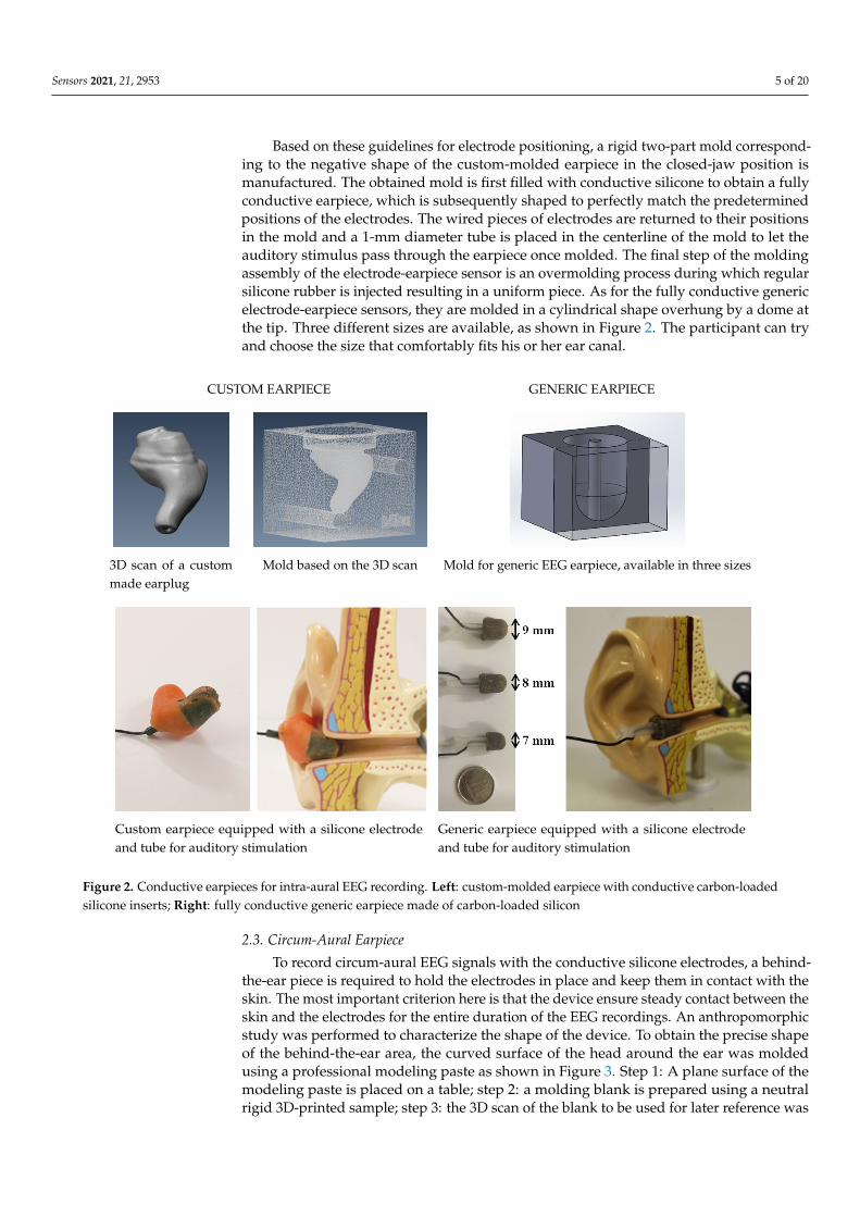
Based on these guidelines for electrode positioning, a rigid two-part mold correspond-ing to the negative shape of the custom-molded earpiece in the closed-jaw position ismanufactured. The obtained mold is first filled with conductive silicone to obtain a fullyconductive earpiece, which is subsequently shaped to perfectly match the predeterminedpositions of the electrodes. The wired pieces of electrodes are returned to their positionsin the mold and a 1-mm diameter tube is placed in the centerline of the mold to let theauditory stimulus pass through the earpiece once molded. The final step of the moldingassembly of the electrode-earpiece sensor is an overmolding process during which regularsilicone rubber is injected resulting in a uniform piece. As for the fully conductive genericelectrode-earpiece sensors, they are molded in a cylindrical shape overhung by a dome atthe tip. Three different sizes are available, as shown in Figure 2. The participant can tryand choose the size that comfortably fits his or her ear canal.
CUSTOM EARPIECE GENERIC EARPIECE
3D scan of a custommade earplug
Mold based on the 3D scan Mold for generic EEG earpiece, available in three sizes
Custom earpiece equipped with a silicone electrodeand tube for auditory stimulation
Generic earpiece equipped with a silicone electrodeand tube for auditory stimulation
Figure 2. Conductive earpieces for intra-aural EEG recording. Left: custom-molded earpiece with conductive carbon-loadedsilicone inserts; Right: fully conductive generic earpiece made of carbon-loaded silicon
2.3. Circum-Aural Earpiece
To record circum-aural EEG signals with the conductive silicone electrodes, a behind-the-ear piece is required to hold the electrodes in place and keep them in contact with theskin. The most important criterion here is that the device ensure steady contact between theskin and the electrodes for the entire duration of the EEG recordings. An anthropomorphicstudy was performed to characterize the shape of the device. To obtain the precise shapeof the behind-the-ear area, the curved surface of the head around the ear was moldedusing a professional modeling paste as shown in Figure 3. Step 1: A plane surface of themodeling paste is placed on a table; step 2: a molding blank is prepared using a neutralrigid 3D-printed sample; step 3: the 3D scan of the blank to be used for later reference was

Sensors 2021, 21, 2953 6 of 20
obtained using an EinScan-S 3D scanner (Shinning3D, Hangzhou, Zhejiang, China); step 4:The molding blank was placed in its position around the ear and pressed onto the surfaceof the head using mild pressure to imprint the behind-the-ear area of the participant;step 5: The resulting impression was 3D scanned; and step 6: it was compared to thegeometric reference plane of the modeling paste. The geometrical differences betweenthe blank reference and the behind-the-ear impression describe the precise shape of thebehind-the-ear area.
(1) Preparation of a plane surface ofmodeling paste
(2) Application on a rigid body (3) 3D scan of the reference shape
(4) Reference shape applied behindthe ear
(5) 3D scan of the deformed shape (6) Geometrical differences betweenreference and deformed shape
Figure 3. Practical steps to obtain the custom shape factor of the behind-the-ear piece.
The behind-the-ear impression process was completed for eight individuals (six males,two females), aged between 21 and 37, with a height between 1.65 m and 1.87 m, allCaucasian. It yielded sixteen (right and left ear) different 3D models of the behind-the-earmorphology. The geometrical models were compared using PolyWorks (v11.0.34, moduleIMinspect). Morphing geometric tools combined with the similar geometric patternsobserved on the sixteen models were used to obtain a unique average-geometry behind-the-ear model. Small cavities were then added to the model to support the conductive siliconeelectrodes. Two different versions of the behind-the-ear piece are illustrated in Figure 4.The first version is suitable for EEG recordings; however it requires the use of a headbandto press the electrodes against the skin and to reach acceptable electrical impedance forthe skin–electrode contact. Given the variety of behind-the-ear geometries among theparticipants, it was difficult to obtain high quality signals for all embedded electrodes.
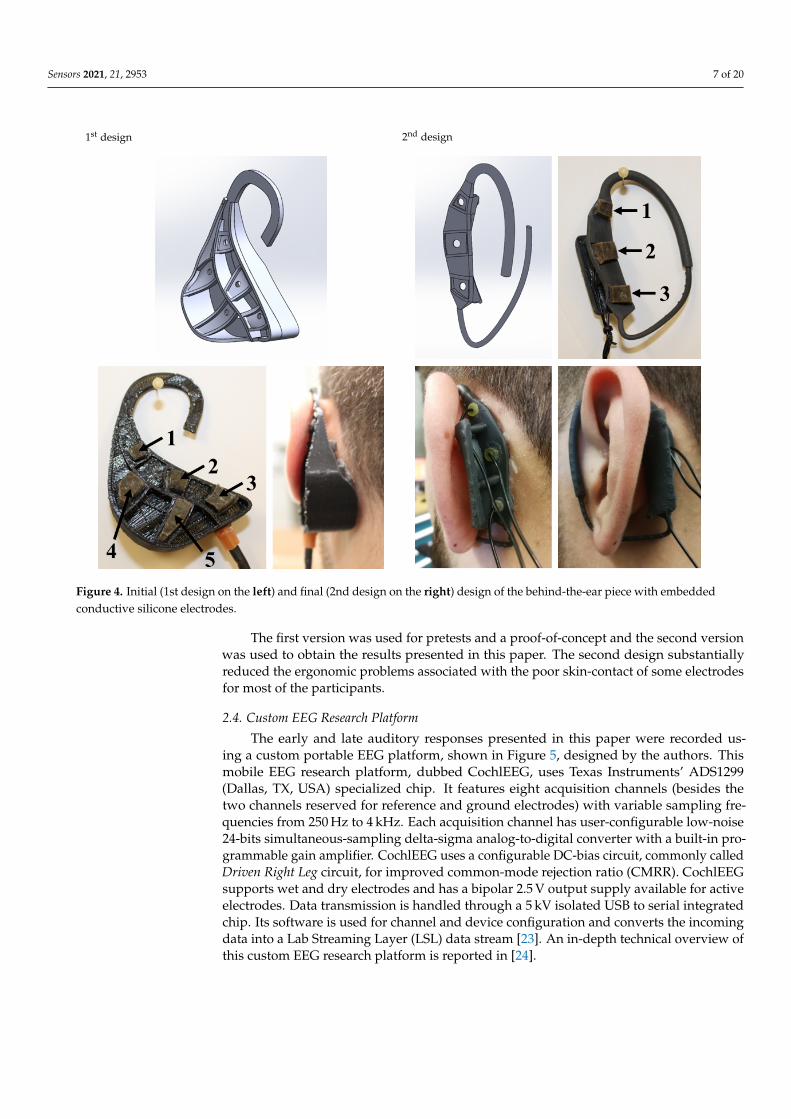
The first version was subsequently modified by reducing it to the zones associatedwith electrode number 1, 2 and 3 as shown in Figure 4. The general shape of the secondversion is still based on the average geometry of the behind-the-ear area. It also contains aV-shape folded structure as shown in Figure 4 to support the behind-the-ear piece againstthe back of the pinna using a spring effect that efficiently presses the electrodes against theskin. In addition, a hook was added to the design to loop around the pinna and steady thebehind-the-ear piece in its position. The frame was 3D printed with a stereo-lithographyprinter (Form2, Formlabs, Somerville. USA) in a flexible acrylic resin.
Sensors 2021, 21, 2953 7 of 20Sensors 2021, 1, 0 7 of 21
1st design 2nd design
Figure 4. Initial (1st design on the left) and final (2nd design on the right) design of the behind-the-ear piece with embeddedconductive silicone electrodes
The first version was used for pretests and a proof-of-concept and the second versionwas used to obtain the results presented in this paper. The second design substantiallyreduced the ergonomic problems associated with the poor skin-contact of some electrodesfor most of the participants.
2.4. Custom EEG Research Platform
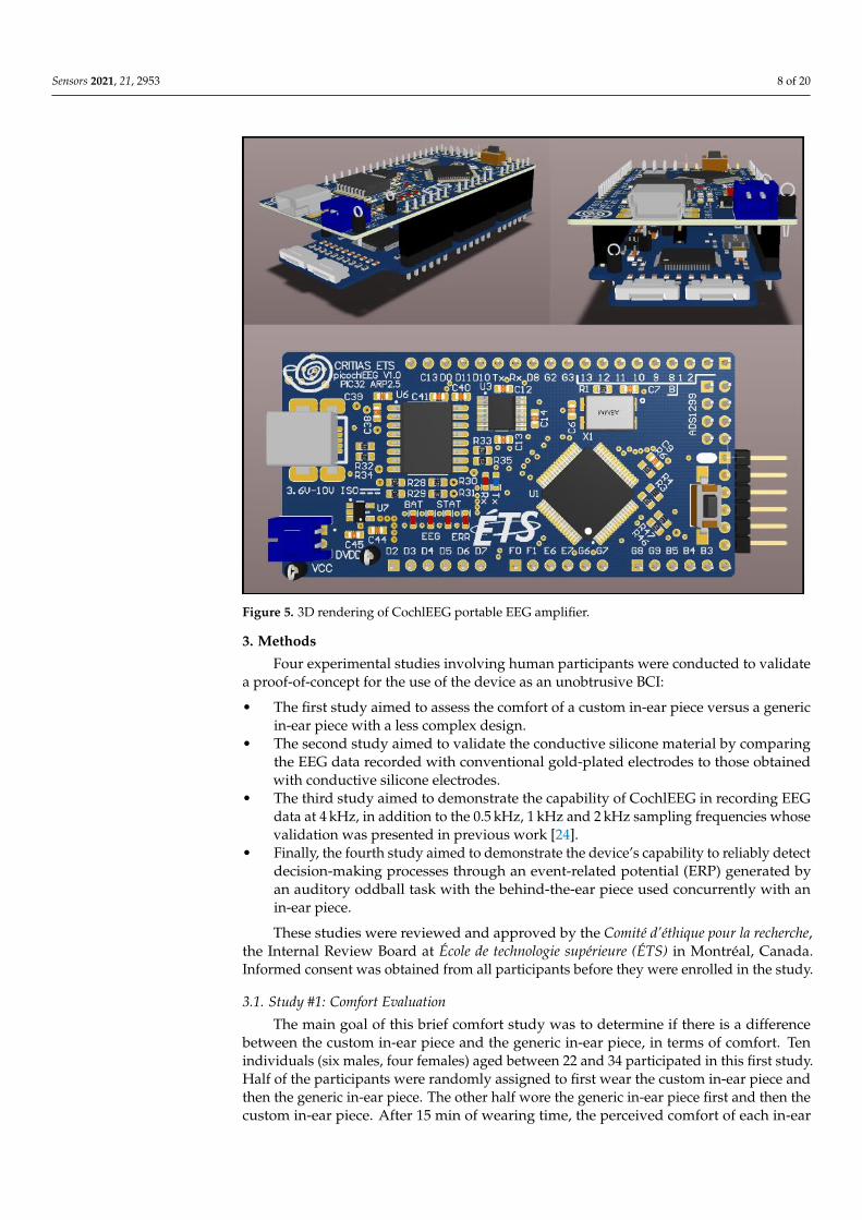
The early and late auditory responses presented in this paper were recorded us-ing a custom portable EEG platform, shown in Figure 5, designed by the authors. Thismobile EEG research platform, dubbed CochlEEG, uses Texas Instruments’ ADS1299(Dallas, TX, USA) specialized chip. It features eight acquisition channels (besides thetwo channels reserved for reference and ground electrodes) with variable sampling fre-quencies from 250 Hz to 4 kHz. Each acquisition channel has user-configurable low-noise24-bits simultaneous-sampling delta-sigma analog-to-digital converter with a built-in pro-grammable gain amplifier. CochlEEG uses a configurable DC-bias circuit, commonly calledDriven Right Leg circuit, for improved common-mode rejection ratio (CMRR). CochlEEGsupports wet and dry electrodes and has a bipolar 2.5 V output supply available for activeelectrodes. Data transmission is handled through a 5 kV isolated USB to serial integratedchip. Its software is used for channel and device configuration and converts the incomingdata into a Lab Streaming Layer (LSL) data stream [32]. An in-depth technical overview ofthis custom EEG research platform is reported in [23].
Figure 4. Initial (1st design on the left) and final (2nd design on the right) design of the behind-the-ear piece with embeddedconductive silicone electrodes.
The first version was used for pretests and a proof-of-concept and the second versionwas used to obtain the results presented in this paper. The second design substantiallyreduced the ergonomic problems associated with the poor skin-contact of some electrodesfor most of the participants.
2.4. Custom EEG Research Platform
The early and late auditory responses presented in this paper were recorded us-ing a custom portable EEG platform, shown in Figure 5, designed by the authors. Thismobile EEG research platform, dubbed CochlEEG, uses Texas Instruments’ ADS1299(Dallas, TX, USA) specialized chip. It features eight acquisition channels (besides thetwo channels reserved for reference and ground electrodes) with variable sampling fre-quencies from 250 Hz to 4 kHz. Each acquisition channel has user-configurable low-noise24-bits simultaneous-sampling delta-sigma analog-to-digital converter with a built-in pro-grammable gain amplifier. CochlEEG uses a configurable DC-bias circuit, commonly calledDriven Right Leg circuit, for improved common-mode rejection ratio (CMRR). CochlEEGsupports wet and dry electrodes and has a bipolar 2.5 V output supply available for activeelectrodes. Data transmission is handled through a 5 kV isolated USB to serial integratedchip. Its software is used for channel and device configuration and converts the incomingdata into a Lab Streaming Layer (LSL) data stream [23]. An in-depth technical overview ofthis custom EEG research platform is reported in [24].
Sensors 2021, 21, 2953 8 of 20
Figure 5. 3D rendering of CochlEEG portable EEG amplifier.
3. Methods
Four experimental studies involving human participants were conducted to validatea proof-of-concept for the use of the device as an unobtrusive BCI:
• The first study aimed to assess the comfort of a custom in-ear piece versus a genericin-ear piece with a less complex design.
• The second study aimed to validate the conductive silicone material by comparingthe EEG data recorded with conventional gold-plated electrodes to those obtainedwith conductive silicone electrodes.
• The third study aimed to demonstrate the capability of CochlEEG in recording EEGdata at 4 kHz, in addition to the 0.5 kHz, 1 kHz and 2 kHz sampling frequencies whosevalidation was presented in previous work [24].
• Finally, the fourth study aimed to demonstrate the device’s capability to reliably detectdecision-making processes through an event-related potential (ERP) generated byan auditory oddball task with the behind-the-ear piece used concurrently with anin-ear piece.
These studies were reviewed and approved by the Comité d’éthique pour la recherche,the Internal Review Board at École de technologie supérieure (ÉTS) in Montréal, Canada.Informed consent was obtained from all participants before they were enrolled in the study.
3.1. Study #1: Comfort Evaluation
The main goal of this brief comfort study was to determine if there is a differencebetween the custom in-ear piece and the generic in-ear piece, in terms of comfort. Tenindividuals (six males, four females) aged between 22 and 34 participated in this first study.Half of the participants were randomly assigned to first wear the custom in-ear piece andthen the generic in-ear piece. The other half wore the generic in-ear piece first and then thecustom in-ear piece. After 15 min of wearing time, the perceived comfort of each in-ear
Sensors 2021, 21, 2953 9 of 20
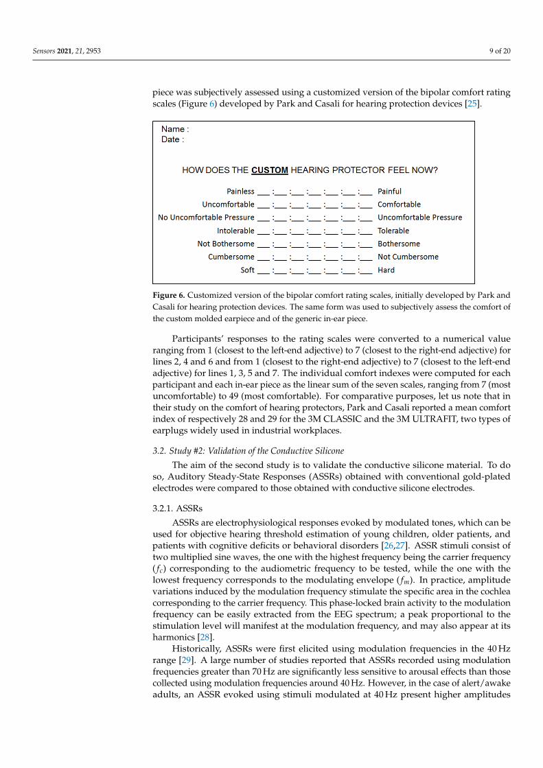
piece was subjectively assessed using a customized version of the bipolar comfort ratingscales (Figure 6) developed by Park and Casali for hearing protection devices [25].
Figure 6. Customized version of the bipolar comfort rating scales, initially developed by Park andCasali for hearing protection devices. The same form was used to subjectively assess the comfort ofthe custom molded earpiece and of the generic in-ear piece.
Participants’ responses to the rating scales were converted to a numerical valueranging from 1 (closest to the left-end adjective) to 7 (closest to the right-end adjective) forlines 2, 4 and 6 and from 1 (closest to the right-end adjective) to 7 (closest to the left-endadjective) for lines 1, 3, 5 and 7. The individual comfort indexes were computed for eachparticipant and each in-ear piece as the linear sum of the seven scales, ranging from 7 (mostuncomfortable) to 49 (most comfortable). For comparative purposes, let us note that intheir study on the comfort of hearing protectors, Park and Casali reported a mean comfortindex of respectively 28 and 29 for the 3M CLASSIC and the 3M ULTRAFIT, two types ofearplugs widely used in industrial workplaces.
3.2. Study #2: Validation of the Conductive Silicone
The aim of the second study is to validate the conductive silicone material. To doso, Auditory Steady-State Responses (ASSRs) obtained with conventional gold-platedelectrodes were compared to those obtained with conductive silicone electrodes.
3.2.1. ASSRs
ASSRs are electrophysiological responses evoked by modulated tones, which can beused for objective hearing threshold estimation of young children, older patients, andpatients with cognitive deficits or behavioral disorders [26,27]. ASSR stimuli consist oftwo multiplied sine waves, the one with the highest frequency being the carrier frequency( fc) corresponding to the audiometric frequency to be tested, while the one with thelowest frequency corresponds to the modulating envelope ( fm). In practice, amplitudevariations induced by the modulation frequency stimulate the specific area in the cochleacorresponding to the carrier frequency. This phase-locked brain activity to the modulationfrequency can be easily extracted from the EEG spectrum; a peak proportional to thestimulation level will manifest at the modulation frequency, and may also appear at itsharmonics [28].
Historically, ASSRs were first elicited using modulation frequencies in the 40 Hzrange [29]. A large number of studies reported that ASSRs recorded using modulationfrequencies greater than 70 Hz are significantly less sensitive to arousal effects than thosecollected using modulation frequencies around 40 Hz. However, in the case of alert/awakeadults, an ASSR evoked using stimuli modulated at 40 Hz present higher amplitudes

Sensors 2021, 21, 2953 10 of 20
and better signal-to-noise ratios, which might provide faster and more efficient ASSRdetection [30,31].
3.2.2. Participants
Ten individuals (six men and four women aged between 22 and 34) participated in thesecond study. They were recruited among students and colleagues. All participants werenormal-hearing (no hearing threshold below 25 dB HL between 125 and 8000 Hz usingtonal audiometry) and were free of past or present neurological conditions.
3.2.3. Auditory Stimuli
In the second experiment, the stimuli were sinusoidal tones with a carrier frequencyof 1000 Hz ( fc) that were 100% amplitude-modulated at 41 Hz ( fm). Equation (1) details thefull mathematical formula used for stimuli generation:
y(t) =sin(2π fc(t))
2× sin(2π fm(t)) + 1
2(1)
All stimuli were generated using a MATLAB R2015b program (Mathworks, Natick,MA, USA) script. They were amplified using an AC40 audiometer (Interacoustic, Mid-delfart, Danemark) before being binaurally presented via E-A-RTONE model 3A insertearphones (Aearo Technologies LLC, Indianapolis, IN, USA) at a stimulation level of75 dB SPL. Stimuli calibration was performed using a B&K2128 Head and Torso Simulator(Brüel & Kjær, Nærum, Danemark).
3.2.4. Recordings
During all the measurements, participants remained seated on a comfortable er-gonomic chair inside a double-walled audiometric booth. ASSR data were collected eitherusing traditional gold wet electrodes or wet electrodes made of conductive silicone. Therecording order was randomly determined for each individual participant using a six-sideddice and a tree diagram (Figure 7).
Figure 7. Tree diagram used to randomly determine the recordings’ order for each individual participant.
Traditionally, ASSR data are collected from an electrode placed at the vertex (Cz) usingan electrode on the back of the neck (below the hairline) as reference and an electrode on theclavicle as ground. Since the aim of this second study is to explore the capability of usingconductive silicone as in-ear electrodes, the exploring, ground and reference electrodeswere placed at the vertex (Cz), on the lobe and into the ear canal respectively.
Sensors 2021, 21, 2953 11 of 20
For the traditional gold electrodes, the exploring electrode consists of a gold-platedcup electrode and the ground electrode is composed of two gold-plated cup electrodesmounted like an ear clip, and the reference electrode is a gold foil electrode with earphonefoam tips. For the conductive silicone electrodes, the exploring electrode is in the form of adisc snapped to a lead wire, the ground electrode consists of a silicone pad mounted like anear clip, and the reference electrode is either a custom earplug with a conductive siliconeelectrode or a fully conductive generic earplug. The recording sites were cleaned usingNuprep abrasive gel (Weaver and Company, Aurora, CO, USA) and alcohol prior to therecording. The conductivity between the skin and all electrodes was ensured using Ten20conductive paste (Weaver and Company). The interelectrode impedance were below 20 kΩat 10 Hz for the traditional gold electrodes and below 60 kΩ at 10 Hz for the conductivesilicone electrodes.
For the second study, ASSR data were recorded with a sampling rate of 1000 Hz usingthe custom EEG research platform presented in Section 2.4. Synchronization between stim-ulation and recording was performed using Lab Streaming Layer (LSL). Data analysis wasperformed offline using MATLAB software and the toolbox EEGLAB [32]. A 0.1–500 HzFIR band-pass filter was applied to ASSR data before extraction of the data sweep. A totalof six sweeps of sixteen epochs each with 1000 points per epoch were extracted from thedata stream, averaged in the time domain, and then translated in the frequency domainusing FFT.
3.3. Study #3: Validation of CochlEEG’s 4 kHz Sampling Rate
The aim of the third study is to validate the capability of CochlEEG to record EEGdata at 4 kHz, in addition to the 0.5 kHz, 1 kHz and 2 kHz sampling frequencies whosevalidation was presented in previous work [24]. To do so, ASSR data obtained usingconventional gold-plated electrodes with a sampling rate of 1000 Hz were compared tothose obtained with a sampling rate of 4000 Hz. Ten individuals (six men and four womenaged between 22 and 34) participated in the third study. They were recruited amongstudents and colleagues. All participants were normal-hearing (no hearing threshold below25 dB HL between 125 and 8000 Hz using tonal audiometry) and were free of past or presentneurological conditions.
In the third experiment, the stimuli were sinusoidal tones with a carrier frequency of1000 and 4000 Hz that were 100% amplitude-modulated at 41 Hz. The methods used to cali-brate, generate, and present the stimuli were the same as the ones described in Section 3.2.3.
Since the aim of this third study is to validate the capability of CochlEEG in recordingEEG data at 4 kHz, ASSR data were collected using traditional gold electrodes with asampling rate of either 1000 Hz or 4000 Hz (the order of presentation being random). Theexploring, ground and reference electrodes were placed at the vertex (Cz), on the ear lobeand in the ear canal respectively. The exploring electrode consists of a gold-plated cupelectrode, the ground electrode is composed of two gold-plated cup electrodes mountedlike an ear clip and the reference electrode is a gold foil electrode with earphone foam tips.All interelectrode impedance were below 20 kΩ at 10 Hz.
The preparation method, recording method, and filtering parameters were the sameas the ones described in Section 3.2.4.
3.4. Study #4: Event-Related Potentials (ERPs)3.4.1. ERPs and the Oddball Paradigm
Event-related potentials (ERP) are important in EEG research because they are causedby the presentation of a stimuli. They translate the brain activity’s response to a specificevent and are time-locked to that event, making them easier to isolate and study. Dependingon the stimulation, you can expect these predictably timed peaks and troughs in voltageamplitude, which correspond to well-known and well-established cognitive processes [33].Many ERPs are described by a letter and a number to indicate the type of polarizationthey represent (Negative or Positive) and the latency or order in which they are found. In
Sensors 2021, 21, 2953 12 of 20
this study, we are interested in the P3 or P300 response, a large positive amplitude waveoccurring around 300 ms after a task-relevant stimuli is presented. The P300 responseindicates that the subject recognizes the stimuli as a target, meaning it is related to decision-making. This makes ERPs and in particular the P300 most relevant for brain–computerinterfaces (BCI) because it is a conscious and voluntary cognitive response [34]. It wastherefore important to use a P300-generating paradigm in this study to demonstrate thecapability of the new electrodes to reliably detect ERPs, validating their compatibility forthe proposed ear-centric EEG acquisition platform.
For this study, an auditory oddball paradigm was chosen to measure a P300 response.Participants heard a series of repetitive tones, interrupted shortly and randomly by adeviant tone clearly higher in frequency. They were asked to pay attention to the devianttones as targets and to count their occurrence while ignoring the standard stimuli [35]. Thedetails of this task are derived from the work of Bennington et al. [36].
3.4.2. Participants
Nine individuals (six males, three females) with ages ranging from 21 to 27, andhearing thresholds below 25 dB HL, were recruited to participate in the fourth study.All participants were free of past or present neurological conditions.
3.4.3. Auditory Stimuli
ERPs were elicited using 40 auditory sequences. Each sequence consists of 10 si-nusoidal tones of 69.8 ms duration (9.9 ms rise/fall and 50 ms plateau) of either 1000 Hz(standard) or 2000 Hz (target). Each stimulus was separated by a 2 s interstimulus intervaland each sequence was separated by a 4-s intersequence interval. All stimuli were stan-dard stimuli except for one that was a target stimulus randomly chosen at either the 7th,8th, 9th or 10th position. The stimulation level was adjusted to a participant-controlledcomfortable loudness, and E-A-RTONE model 3A insert earphones (Aearo TechnologiesLLC, Indianapolis, IN, USA) were used to deliver the stimuli.
3.4.4. Recordings
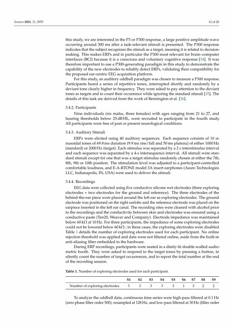
EEG data were collected using five conductive silicone wet electrodes (three exploringelectrodes + two electrodes for the ground and reference). The three electrodes of thebehind-the-ear piece were placed around the left ear as exploring electrodes. The groundelectrode was positioned on the right earlobe and the reference electrode was placed on theearpiece inserted in the left ear canal. The recording sites were cleaned with alcohol priorto the recordings and the conductivity between skin and electrodes was ensured using aconductive paste (Ten20, Weaver and Company). Electrode impedance was maintainedbelow 60 kΩ at 10 Hz. For three participants, the impedance of some exploring electrodescould not be lowered below 60 kΩ ; in these cases, the exploring electrodes were disabled.Table 1 details the number of exploring electrodes used for each participant. No onlinerejection threshold was applied and data were not filtered online, aside from the built-inanti-aliasing filter embedded in the hardware.
During ERP recordings, participants were seated in a dimly-lit double-walled audio-metric booth. They were asked to respond to the target tones by pressing a button, tosilently count the number of target occurrences, and to report the total number at the endof the recording session.
Table 1. Number of exploring electrodes used for each participant.
S1 S2 S3 S4 S5 S6 S7 S8 S9
Number of exploring electrodes 3 3 3 3 3 1 3 2 2
To analyze the oddball data, continuous time series were high-pass filtered at 0.1 Hz(zero phase filter order 500), resampled at 128 Hz, and low-pass filtered at 30 Hz (filter order
Sensors 2021, 21, 2953 13 of 20
100). They were then epoched from −500 to 1000 ms and baseline corrected (−500 to 0 ms).Data recorded with less than two acquisition channels were not included in the analysis(i.e., participant S6). Artifact removal was performed using the EEGLAB 2019 toolbox asfollows: An independent component analysis (ICA) was performed [37] on the data ofparticipants who had all three exploring electrodes active at all times, generating threecomponents. For these participants, one main eye-blink artifact component was identifiedfor rejection using the component data scrolls and looking for obvious eye blinks andlongitudinal eye movements. The projections of this component were then removed fromeach of the three electrode time series data. Additionally, for every participant, improbablemuscular artifacts were identified using the probability and kurtosis criteria (standarddeviation: 3) and rejected from further analysis (3%-to-10% of epochs were rejected usingthis criterion). After this preprocessing phase, the time series data was passed through amoving average FIR filter (zero phase filter order 8) to smooth out the data.
4. Results4.1. Comfort of the In-Ear Pieces
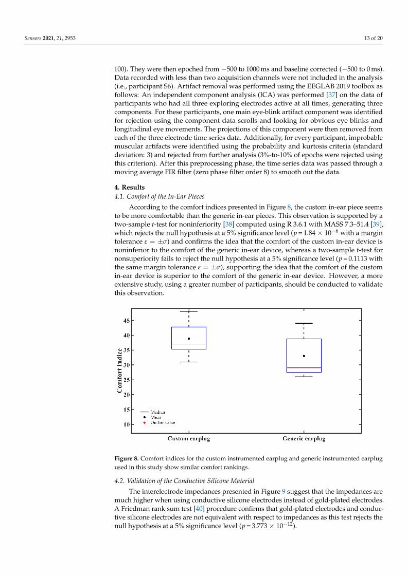
According to the comfort indices presented in Figure 8, the custom in-ear piece seemsto be more comfortable than the generic in-ear pieces. This observation is supported by atwo-sample t-test for noninferiority [38] computed using R 3.6.1 with MASS 7.3–51.4 [39],which rejects the null hypothesis at a 5% significance level (p = 1.84 × 10⁻⁶ with a margintolerance ε = ±σ) and confirms the idea that the comfort of the custom in-ear device isnoninferior to the comfort of the generic in-ear device, whereas a two-sample t-test fornonsuperiority fails to reject the null hypothesis at a 5% significance level (p = 0.1113 withthe same margin tolerance ε = ±σ), supporting the idea that the comfort of the customin-ear device is superior to the comfort of the generic in-ear device. However, a moreextensive study, using a greater number of participants, should be conducted to validatethis observation.
Figure 8. Comfort indices for the custom instrumented earplug and generic instrumented earplugused in this study show similar comfort rankings.
4.2. Validation of the Conductive Silicone Material
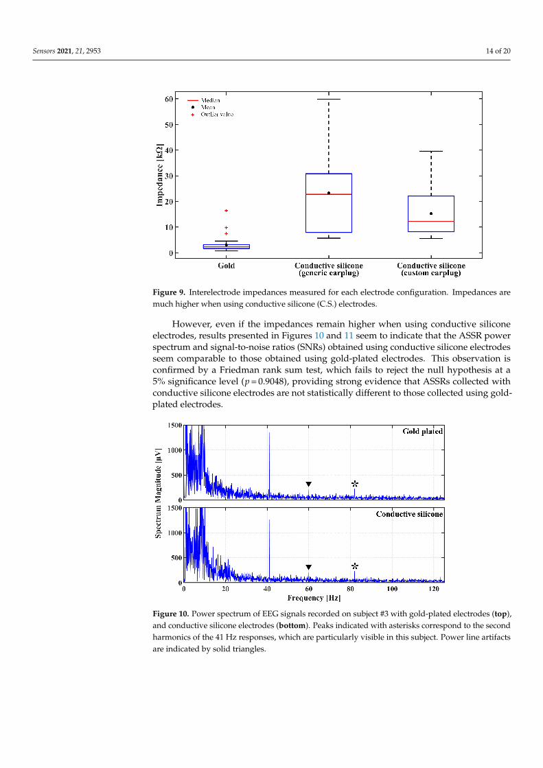
The interelectrode impedances presented in Figure 9 suggest that the impedances aremuch higher when using conductive silicone electrodes instead of gold-plated electrodes.A Friedman rank sum test [40] procedure confirms that gold-plated electrodes and conduc-tive silicone electrodes are not equivalent with respect to impedances as this test rejects thenull hypothesis at a 5% significance level (p = 3.773 × 10⁻¹²).
Sensors 2021, 21, 2953 14 of 20
Figure 9. Interelectrode impedances measured for each electrode configuration. Impedances aremuch higher when using conductive silicone (C.S.) electrodes.
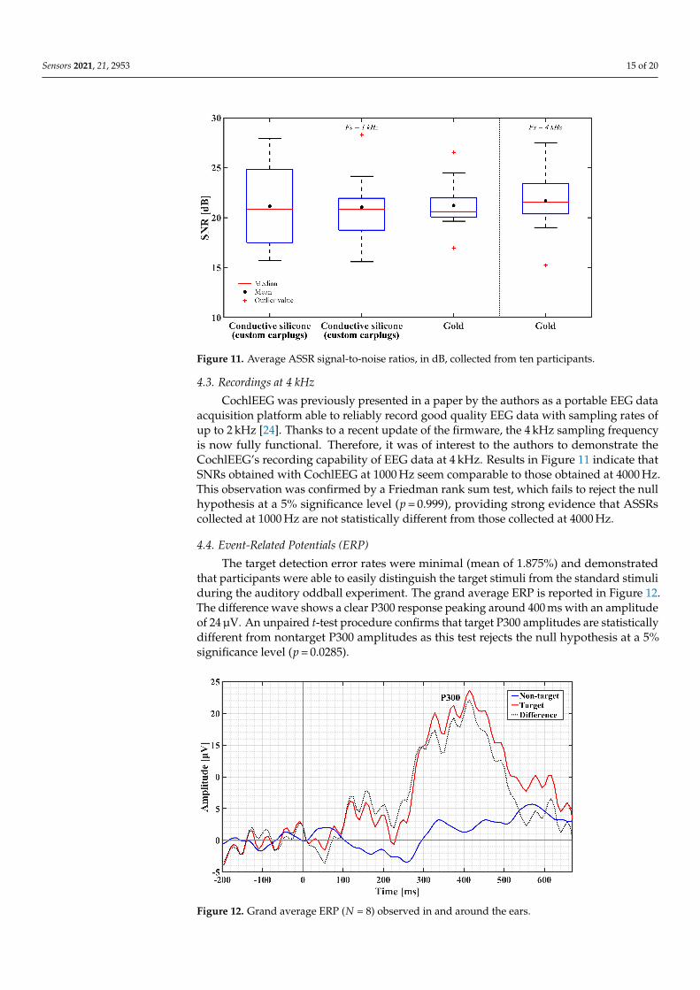
However, even if the impedances remain higher when using conductive siliconeelectrodes, results presented in Figures 10 and 11 seem to indicate that the ASSR powerspectrum and signal-to-noise ratios (SNRs) obtained using conductive silicone electrodesseem comparable to those obtained using gold-plated electrodes. This observation isconfirmed by a Friedman rank sum test, which fails to reject the null hypothesis at a5% significance level (p = 0.9048), providing strong evidence that ASSRs collected withconductive silicone electrodes are not statistically different to those collected using gold-plated electrodes.
Figure 10. Power spectrum of EEG signals recorded on subject #3 with gold-plated electrodes (top),and conductive silicone electrodes (bottom). Peaks indicated with asterisks correspond to the secondharmonics of the 41 Hz responses, which are particularly visible in this subject. Power line artifactsare indicated by solid triangles.
Sensors 2021, 21, 2953 15 of 20
Figure 11. Average ASSR signal-to-noise ratios, in dB, collected from ten participants.
4.3. Recordings at 4 kHz
CochlEEG was previously presented in a paper by the authors as a portable EEG dataacquisition platform able to reliably record good quality EEG data with sampling rates ofup to 2 kHz [24]. Thanks to a recent update of the firmware, the 4 kHz sampling frequencyis now fully functional. Therefore, it was of interest to the authors to demonstrate theCochlEEG’s recording capability of EEG data at 4 kHz. Results in Figure 11 indicate thatSNRs obtained with CochlEEG at 1000 Hz seem comparable to those obtained at 4000 Hz.This observation was confirmed by a Friedman rank sum test, which fails to reject the nullhypothesis at a 5% significance level (p = 0.999), providing strong evidence that ASSRscollected at 1000 Hz are not statistically different from those collected at 4000 Hz.
4.4. Event-Related Potentials (ERP)
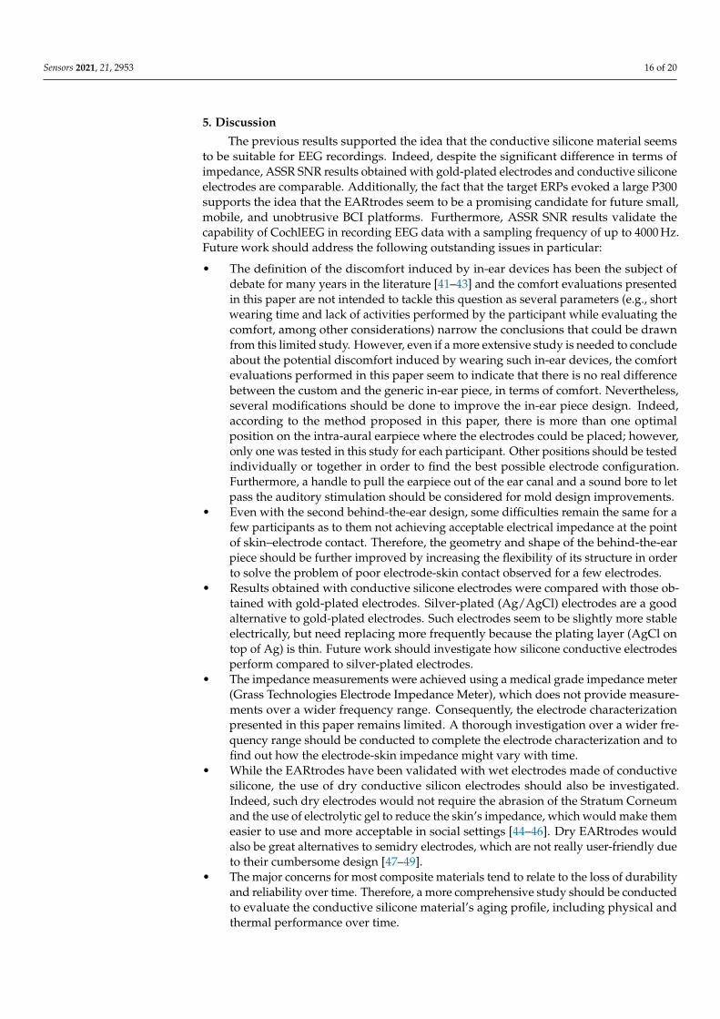
The target detection error rates were minimal (mean of 1.875%) and demonstratedthat participants were able to easily distinguish the target stimuli from the standard stimuliduring the auditory oddball experiment. The grand average ERP is reported in Figure 12.The difference wave shows a clear P300 response peaking around 400 ms with an amplitudeof 24 µV. An unpaired t-test procedure confirms that target P300 amplitudes are statisticallydifferent from nontarget P300 amplitudes as this test rejects the null hypothesis at a 5%significance level (p = 0.0285).
Figure 12. Grand average ERP (N = 8) observed in and around the ears.
Sensors 2021, 21, 2953 16 of 20
5. Discussion
The previous results supported the idea that the conductive silicone material seemsto be suitable for EEG recordings. Indeed, despite the significant difference in terms ofimpedance, ASSR SNR results obtained with gold-plated electrodes and conductive siliconeelectrodes are comparable. Additionally, the fact that the target ERPs evoked a large P300supports the idea that the EARtrodes seem to be a promising candidate for future small,mobile, and unobtrusive BCI platforms. Furthermore, ASSR SNR results validate thecapability of CochlEEG in recording EEG data with a sampling frequency of up to 4000 Hz.Future work should address the following outstanding issues in particular:
• The definition of the discomfort induced by in-ear devices has been the subject ofdebate for many years in the literature [41–43] and the comfort evaluations presentedin this paper are not intended to tackle this question as several parameters (e.g., shortwearing time and lack of activities performed by the participant while evaluating thecomfort, among other considerations) narrow the conclusions that could be drawnfrom this limited study. However, even if a more extensive study is needed to concludeabout the potential discomfort induced by wearing such in-ear devices, the comfortevaluations performed in this paper seem to indicate that there is no real differencebetween the custom and the generic in-ear piece, in terms of comfort. Nevertheless,several modifications should be done to improve the in-ear piece design. Indeed,according to the method proposed in this paper, there is more than one optimalposition on the intra-aural earpiece where the electrodes could be placed; however,only one was tested in this study for each participant. Other positions should be testedindividually or together in order to find the best possible electrode configuration.Furthermore, a handle to pull the earpiece out of the ear canal and a sound bore to letpass the auditory stimulation should be considered for mold design improvements.
• Even with the second behind-the-ear design, some difficulties remain the same for afew participants as to them not achieving acceptable electrical impedance at the pointof skin–electrode contact. Therefore, the geometry and shape of the behind-the-earpiece should be further improved by increasing the flexibility of its structure in orderto solve the problem of poor electrode-skin contact observed for a few electrodes.
• Results obtained with conductive silicone electrodes were compared with those ob-tained with gold-plated electrodes. Silver-plated (Ag/AgCl) electrodes are a goodalternative to gold-plated electrodes. Such electrodes seem to be slightly more stableelectrically, but need replacing more frequently because the plating layer (AgCl ontop of Ag) is thin. Future work should investigate how silicone conductive electrodesperform compared to silver-plated electrodes.
• The impedance measurements were achieved using a medical grade impedance meter(Grass Technologies Electrode Impedance Meter), which does not provide measure-ments over a wider frequency range. Consequently, the electrode characterizationpresented in this paper remains limited. A thorough investigation over a wider fre-quency range should be conducted to complete the electrode characterization and tofind out how the electrode-skin impedance might vary with time.
• While the EARtrodes have been validated with wet electrodes made of conductivesilicone, the use of dry conductive silicon electrodes should also be investigated.Indeed, such dry electrodes would not require the abrasion of the Stratum Corneumand the use of electrolytic gel to reduce the skin’s impedance, which would make themeasier to use and more acceptable in social settings [44–46]. Dry EARtrodes wouldalso be great alternatives to semidry electrodes, which are not really user-friendly dueto their cumbersome design [47–49].
• The major concerns for most composite materials tend to relate to the loss of durabilityand reliability over time. Therefore, a more comprehensive study should be conductedto evaluate the conductive silicone material’s aging profile, including physical andthermal performance over time.
Sensors 2021, 21, 2953 17 of 20
6. Conclusions
The EARtrodes were presented in this paper as a lightweight and inconspicuous ear-centered device with the intention of enabling future innovative mobile EEG applications.The performance of the minielectrodes made of conductive silicone embedded in thedevice was evaluated with a custom 8-channel portable EEG research platform under twoelectrophysiological paradigms (ASSRs and ERPs). The ASSR results prove the capacity ofthe minielectrodes made of conductive silicone to reliably record good quality EEG data.The ERP results demonstrate that the ear-centered device can record a reliable P300 responseand differentiate between target and nontarget stimuli responses, making it suitable fordata acquisition for various applications in BCI like P300 spellers, among others. A moreextensive ERP study, with a higher number of participants should be conducted to improveour generalization capability and better adapt to intersubject variability, an importantparameter to consider in future BCI applications and machine learning algorithms.
In-ear sensors seemed to be relatively well tolerated by the participant whether theywere embedded in a generic or custom-fitted earplug. Consequently, a product based onsuch technology would be a highly innovative earpiece able to noninvasively monitor di-verse biosignals. Such BCIs have the potential to become the ultimate wearable technologywith applications in the fields of neurogaming, military and telemedicine. Many researchactivities aiming towards a more comprehensive understanding of human brain functionunder natural conditions may also benefit from such technology, thanks to applications inthe area of assistive technologies, neurorehabilitation and ubiquitous healthcare.
ASSRs results obtained at 4 kHz prove the capacity of CochlEEG to reliably recordEEG signals with a 4 kHz sampling frequency. Consequently, when merged with CochlEEG,EARtrodes also benefit from high sampling rates, which opens up new possibilities forbrainstem applications such as the automatic adjustment of hearing aids based on speech-evoked Frequency Following Responses (FFR) [50] or the fast diagnostic of brain-traumaticinjuries based on FFR classification that would help to overcome the limitations of currentdiagnostic tools, which are time-consuming and require access to a nearby clinical facilityand trained medical specialists [51].
Author Contributions: The authors all contributed equally to this work. ASSR data were collectedand processed by O.V. and ERP data were collected by O.V. and processed by O.V. and G.C.-R. Theear canal’s dynamic deformations study was performed by A.D. The anthropomorphic study wasconducted by G.V. The behind-the-ear and in-ear pieces were designed by G.V. and A.D., with thehelp of O.V. regarding electrode placement, and the expertise shared by J.V. The custom 8-channelportable EEG research platform was developed by M.D. and H.M.-C., with the help of O.V. regardingthe preliminary validations on human subjects. The statistical analysis was performed by O.V. (ASSR)and G.C.-R. (ERP). J.V. was the principal investigator of this research project. He provided helpfulcomments and suggestions on the manuscript and critical revision as well. All authors discussed theresults and implications and commented on the manuscript at all stages. All authors have read andagreed to the published version of the manuscript.
Funding: This research was funded by MITACS Elevation program, grant number IT07737.
Institutional Review Board Statement: The study was conducted according to the guidelines of theDeclaration of Helsinki, and approved by the Comité d’éthique pour la recherche, the Internal ReviewBoard at École de technologie supérieure (ÉTS) in Montréal, QC, Canada (ethical approval #H20160902).
Informed Consent Statement: Written informed consent has been obtained from the participantsbefore they were enrolled in the study.
Data Availability Statement: Data sharing not applicable.
Acknowledgments: The authors wish to acknowledge the financial support received from theNSERC-EERS Industrial Research Chair in In-Ear Technologies (CRITIAS), as well as from MITACSElevation program and the technical support received from EERS Global Technologies Inc. Theauthors would also like to acknowledge Félix Camirand Lemyre and Jean-Philippe Morissette fortheir helpful comments on the manuscript.

Sensors 2021, 21, 2953 18 of 20
Conflicts of Interest: The authors declare no conflict of interest.
AbbreviationsThe following abbreviations are used in this manuscript:
ASSR Auditory steady-state responseBCI Brain–computer interfacedB DecibelEEG ElectroencephalographyERP Event-related potentialsFFT Fast Fourier transformHL Hearing levelHRA Rockwell A-scale hardnessICA Independent component analysisMMN Mismatch negativityRMS Root mean squareTMJ Temporomandibular joint
References1. Machado, S.; Arauro, F.; Paes, F.; Velasques, B.; Cunha, M.; Budde, H.; Basile, L.; Anghinah, R.; Arias-Carrión, O.; Cagy, M.;
et al. EEG-based Brain-Computer Interfaces: An Overview of Basic Concepts and Clinical Applications in Neurorehabilitation.Rev. Neurosci. 2010, 21, 451–468. [CrossRef]
2. Kappel, S.L.; Looney, D.; Mandic, D.P.; Kidmose, P. Physiological artifacts in scalp EEG and ear-EEG. Biomed. Eng. Online 2017,16, 103. [CrossRef]
3. Kidmose, P.; Looney, D.; Mandic, D.P. Auditory evoked responses from Ear-EEG recordings. In Proceedings of the AnnualInternational Conference of the IEEE Engineering in Medicine and Biology Society, San Diego, CA, USA, 28 August–1 September2012; Volume 2012, p. 586.
4. Kidmose, P.; Looney, D.; Ungstrup, M.; Rank, M.; Mandic, D. A Study of Evoked Potentials from Ear-EEG. IEEE Trans. Biomed.Eng. 2013, 60, 2824–2830 . [CrossRef]
5. Mikkelsen, K.B.; Kappel, S.L.; Mandic, D.P.; Kidmose, P. EEG Recorded from the Ear: Characterizing the Ear-EEG Method.Front. Neurosci. 2015, 9, 438. [CrossRef]
6. Goverdovsky, V.; Looney, D.; Kidmose, P.; Mandic, D.P. In-Ear EEG From Viscoelastic Generic Earpieces: Robust and Unobtrusive24/7 Monitoring. IEEE Sens. J. 2016, 16, 271–277. [CrossRef]
7. Goverdovsky, V.; Rosenberg, W.V.; Nakamura, T.; Looney, D.; Sharp, D.; Papavassiliou, C.; Morell, M.; Mandic, D. Hearables:Multimodal physiological in-ear sensing. Sci. Rep. 2017, 7, 6948. [CrossRef]
8. Simon, P.K.; Kappel, L.; Rank, M.L.; Toft, H.O.; Andersen, M. Dry-Contact Electrode Ear-EEG. IEEE Trans. Biomed. Eng. 2018, 66,150–158.
9. Nguyen, A.; Alqurashi, R.; Raghebi, Z.; Banaei-Kashani, F.; Halbower, A.C.; Vu, T. LIBS: A Bioelectrical Sensing System fromHuman Ears for Staging Whole-Night Sleep Study. Commun. ACM 2018, 61, 157–165. [CrossRef]
10. Valle, B.G.D.; Cash, S.S.; Sodini, C.G. Wireless behind-the-ear EEG recording device with wireless interface to a mobile device(iPhone/iPod touch). In Proceedings of the 2014 36th Annual International Conference of the IEEE Engineering in Medicine andBiology Society, Chicago, IL, USA, 26–30 August 2014; pp. 5952–5955.
11. Norton, J.S.; Sup, L.D.; Woo, L.J.; Woosik, L.; Ohjin, K.; Won, P.; Jung, S.Y. Soft, curved electrode systems capable of integration onthe auricle as a persistent brain–computer interface. Proc. Natl. Acad. Sci. USA 2015, 112, 3920–3925. [CrossRef] [PubMed]
12. Debener, S.; Emkes, R.; Vos, M.D.; Bleichner, M. Unobtrusive ambulatory EEG using a smartphone and flexible printed electrodesaround the ear. Sci. Rep. 2015, 5, 1–11. [CrossRef] [PubMed]
13. Bleichner, M.G.; Debener, S. Concealed, Unobtrusive Ear-Centered EEG Acquisition: cEEGrids for Transparent EEG. Front. Hum.Neurosci. 2017, 11, 163. [CrossRef]
14. Mirkovic, B.; Bleichner, M.G.; Vos, M.D.; Debener, S. Target Speaker Detection with Concealed EEG Around the Ear. Front. Neurosci.2016, 10, 349. [CrossRef]
15. Sterr, A.; Ebajemito, J.K.; Mikkelsen, K.B.; Bonmati-Carrion, M.A.; Santhi, N.; della, M.C.; Grainger, L. Sleep EEG Derived FromBehind-the-Ear Electrodes (cEEGrid) Compared to Standard Polysomnography: A Proof of Concept Study. Front. Hum. Neurosci.2018, 12, 452. [CrossRef] [PubMed]
16. Gu, Y.; Cleeren, E.; Dan, J.; Claes, K.; Paesschen, W.V.; Huffel, S.V.; Hunyadi, B. Comparison between Scalp EEG and Behind-the-Ear EEG for Development of a Wearable Seizure Detection System for Patients with Focal Epilepsy. Sensors 2017, 18, 29.[CrossRef] [PubMed]
17. Bleichner, M.G.; Lundbeck, M.; Selisky, M.; Minow, F.; Jager, M.; Emkes, R.; Debener, S.; Vos, M.D. Exploring miniaturized EEGelectrodes for brain-computer interfaces. An EEG you do not see? Physiol. Rep. 2015, 3, 1–9. [CrossRef] [PubMed]

Sensors 2021, 21, 2953 19 of 20
18. Ahn, J.W.; Ku, Y.; Kim, D.Y.; Sohn, J.; Kim, J.-H.; Kim, H.C. Wearable in-the-ear EEG system for SSVEP-based brain–computerinterface. Electron. Lett. 2018, 54, 413–414. [CrossRef]
19. Lee, J.H.; Lee, S.M.; Byeon, H.J.; Hong, J.S.; Park, K.S.; Lee, S.-H. CNT/PDMS-based canal-typed ear electrodes for inconspicuousEEG recording. J. Neural Eng. 2014, 11, 046014.
20. He, W.; Sun, Y.; Xi, J.; Abdurhman, A.A.M.; Ren, J.; Duan, H. Printing graphene-carbon nanotube-ionic liquid gel on graphenepaper: Towards flexible electrodes with efficient loading of PtAu alloy nanoparticles for electrochemical sensing of blood glucose.Anal. Chim. Acta 2016, 903, 61–68. [CrossRef] [PubMed]
21. Manabe, H.; Fukumoto, M.; Yagi, T . Conductive rubber electrodes for earphone-based eye gesture input interface. Pers. Ubiquit.Comput. 2014, 19, 143--154. [CrossRef]
22. Delnavaz, A.; Voix, J. Ear Canal Dynamic Motion as a Source of Power for In-Ear Devices. J. Appl. Phys. 2013, 113, 1–9. [CrossRef]23. Kothe, C. Lab Streaming Layer (LSL). Available: https://github.com/sccn/labstreaminglayer/(accessed on 17 June 2019).24. Valentin, O.; Ducharme, M.; Cretot-Richert, G.; Monsarrat-Chanon, H.; Viallet, G.; Delnavaz, A.; Voix, J. Validation and
Benchmarking of a Wearable EEG Acquisition Platform for Real-World Applications. IEEE Trans. Biomed. Circuits Syst. 2018, 13,103–111. [CrossRef] [PubMed]
25. Park, M.Y.; Casali, J.G. An empirical study if comfort afforded by various hearing protection devices: laboratory versus fieldresults. Appl. Acoust. 1991, 34, 151–179. [CrossRef]
26. Cone-Wesson, B.; Dowell, R.C.; Tomlin, D.; Rance, G.; Ming, W.J. The auditory steady-state response: Comparisons with theauditory brainstem response. J. Am. Acad. Audiol. 2002, 13, 173–183.
27. Picton, T.W.; John, M.S.; Dimitrijevic, A.; Purcell, D. Human auditory steady state responses. Int. J. Audiol. 2003, 42, 177–219.[CrossRef]
28. John, M.S.; Lins, O.G.; Boucher, B.L.; Picton, T.W. Multiple auditory steady-state responses (MASTER): Stimulus and recordingparameters. Audiology 1998, 37, 59–82. [CrossRef]
29. Galambos, R.; Makeig, A.; Talmachoff, P.J. A 40-Hz auditory potential recorded from the human scalp. Proc. Natl. Acad. Sci. USA1981, 78, 2643—2647. [CrossRef]
30. Dimitrijevic, A.; John, M.S.; Roon, P.V.; Picton, T.W. Human auditory steady-state responses to tones independently modulated inboth frequency and amplitude. Ear Hear 2001, 22, 100–111. [CrossRef] [PubMed]
31. Maanen, A.V.; Stapells, D.R. Comparison of multiple auditory steady state responses (80 versus 40Hz) and slow cortical potentialsfor threshold estimation in hearing-impaired adults. Int. J. Audiol. 2005, 44, 613–624. [CrossRef] [PubMed]
32. Delorme, A.; Makeig, S. EEGLAB: An open source toolbox for analysis of single-trial EEG dynamics including independentcomponent analysis. J. Neurosci. Methods 2004, 15, 9–21. [CrossRef]
33. Luck, S.J.; Kappenman, E.S. The Oxford Handbook of Event-Related Potential Components; Oxford University Press: Hong Kong,China, 2012.
34. Graimann, B.; Allison, B.; Pfurtscheller, G. Brain-Computer Interfaces; Springer: Heidelberg, Germany, 2010. [CrossRef]35. Donchin, E.; Coles, M.G. Is the P300 component a manifestation of context updating? Behav. Brain Sci. 1988, 11, 357–427.
[CrossRef]36. Bennington, J.Y.; Polich, J. Comparison of P300 from passive and active tasks for auditory and visual stimuli. Int. J. Psychophysiol.
1999, 34, 171–177. [CrossRef]37. Hoffmann, S.; Falkenstein, M. The correction of eye blink artefacts in the EEG: A comparison of two prominent methods. PLoS
ONE 2008, 3, e3004. [CrossRef]38. Wellek, S. Testing Statistical Hypotheses of Equivalence and Noniferiority, 2nd ed.; Chapman & Hall: Boca Raton, FL, USA, 2010.39. R Development Core Team. R: A Language and Environment for Statistical Computing; R Foundation for Statistical Computing:
Vienna, Austria, 2014; ISBN 3-900051-07-0. Available online: http://www.R-project.org/ (accessed on 17 June 2019).40. Wayne, W.D. Friedman Two-Way Analysis of Variance by Ranks, 2nd, ed.; Applied Nonparametric Statistics; PWS-Kent: Boston,
MA, USA, 1990; pp. 262–274.41. Davis, R.R. What do we know about hearing protector comfort? Noise Health 2008, 10, 83–89. [CrossRef]42. Kuijt-Evers, L.F.M.; Groenesteijn, L.; de Looze, M.P.; Vink, P. Identifying factors of comfort in using hand tools. Appl. Ergon. 2004,
35, 453–458. [CrossRef]43. Pearson, E.J.M. Comfort and its measurement—A literature review. Disabil. Rehabil. Assist. Technol. 2009, 4, 301–310. [CrossRef]
[PubMed]44. Lin, C.T.; Liao, L.D.; Liu, Y.H.; Wang, I.J.; Lin, B.S.; Chang, J.Y. Novel dry polymer foam electrodes for long-term EEG measurement.
IEEE Trans. Biomed. Eng. 2011, 58, 1200–1207. [PubMed]45. Lopez-Gordo, M.A.; Sanchez-Morillo, D.; Valle, F.P. Dry EEG Electrodes. Sensors 2014, 14, 12847–12870. [CrossRef] [PubMed]46. Li, G.; Wu, J.; Xia, Y.; Wu, Y.; Tian, Y.; Liu, J.; Chen, D.; He, Q. Towards emerging EEG applications: A novel printable flexible
Ag/AgCl dry electrode array for robust recording of EEG signals at forehead sites. J. Neural Eng. 2020, 17, 026001. [CrossRef][PubMed]
47. Li, G.; Zhang, D.; Wang, S.; Duan, Y.Y. Novel passive ceramic based semi-dry electrodes for recording electroencephalographysignals from the hairy scalp. Sens. Actuators Chem. 2016, 237, 167–178. [CrossRef]
48. Li, G.; Wu, J.T.; Xia, Y.H.; He, Q.G.; Jin, H.G. Review of semi-dry electrodes for EEG recording. J. Neural Eng. 2020, 17, 051004.[CrossRef]

Sensors 2021, 21, 2953 20 of 20
49. Li, G.; Wang, S.; Li, M.; Duan, Y.Y. Towards Real-life EEG applications: Novel Superporous Hydrogel-Based Semi-dry EEGElectrodes Enabling Automatically “Charge-discharge” Electrolyte. J. Neural Eng. 2021, 8, 046016. [CrossRef] [PubMed]
50. Heffernan, B.; Dajani, H.R.; Giguère, C. Towards Developing a Brain-computer Interface for Automatic Hearing Aid Fitting basedon the Speech-evoked Frequency Following Response. In NEUROTECHNIX 2017-Extended Abstracts; SciTePress—Science andTechnology Publications: Funchal, Portugal, 2017; pp. 3–4.
51. Kraus, N.; Thompson, E.; Krizman, J.; Cook, K.; White-Schwoch, T.; LaBella, C.-R. Auditory biological marker of concussion inchildren. Sci. Rep. 2016, 6, 39009. [CrossRef] [PubMed]