Embed Size (px)
Citation preview

Alekh Beri/Mechanical/FRC 5422
Custom Tank Tread White Paper
This paper describes the design and build of a custom tank drive for a robot. This tank
drive is very different from most other FRC drive trains.

Custom Tank Tread
Beri 1
Introduction
A tank drive gives a robot the capability to maneuver over non‐uniform surfaces. Usually a tank drive
is not very agile as it is made to have more torque than speed. However, a well‐designed tank drive can
overcome the speed limitations of COTS (Commercial Off‐The‐Shelf) tank drives. Our robot had to
climb over a multitude of different terrains. Our solution was to make a tank drive with gas shocks to
provide suspension for this challenge.
Design
Some of the advantages of using a tank drive over wheels is more surface area to contact the treads,
spreading weight, varying angles of approach, and being perfect for all possible obstructions and
surfaces, along with improved stability, traction and torque. However there are a few disadvantages of
a tank drive, as it is slow and not easy to maneuver around the field with precision. However, if
designed correctly, the drive can be fast and maneuverable on various terrains.
Factors of consideration:
Suspension – Suspension is important for the robot to absorb the impact of kinetic energy displaced
by moving over rough terrain
Tread Selection – Proper selection of tank treads is a key factor to maintain traction while driving.
Speed – It is difficult to maintain speed while crossing obstacles but a well‐designed drive will take
this into account and maintains a constant speed while traversing obstacles.
Materials – The material has to be lightweight and strong. Lightweight for speed control, and
strength for the massive beating the drive has to take during the match.
Adding Suspension
Suspension designs are typically based on either mechanical springs or gas shocks/struts or even a
combination of both. Mechanical springs store energy by straining the coils and gas struts store energy
by compressing Nitrogen gas (N2). Gas shocks are used in other applications like opening windows,
frames, etc. The advantage of the gas shocks is that less force is required compared to mechanical
springs for the same amount of work.
Another advantage of gas shocks over mechanical springs is the level of damping that is present in gas
shocks but not springs. Damping prevents the oscillation and vibration of the shaft when compressed.
For example, take a compressed spring fixed in place. When the spring is released, then the spring will
extend past its free length, then compress back to less than its free length, and so on until it reaches its
true free length. Because of the damping in gas shocks, compression and expansion is at a controlled
rate.
Most manufacturers will provide the technical specifications for the gas strut selection. So for choosing
the gas strut, it must have enough force to hold the suspension. You also need to know the extended
and compressed length for the open and close position. Example gas shock with Threaded Ends 30 lbs.
Force, 8.15ʺ Extended Length, 3.54ʺ Stroke (Mc Master 9416K312).

Custom Tank Tread
Beri 2
Gas shocks work on Boyles’s law, as the gas shock is compressed, the shaft enters the body, reducing
the internal volume and increasing the internal pressure. When the shaft is at the end of the stroke the
pressure is at the end of the stroke and maximum pressure and the shaft returns to original position.
P1V1 = P2V2
For a gas shock that has 0.25” shaft diameter, 3” stroke, 500 psi charge pressure and 1.24 in3 initial
volume:
V1=1.24, P1=500 psi
V2= V1‐(Stroke * cross sectional area of shaft) = V1‐(Stroke * πr2) = 1.24‐(3*π*0.125*0.125)=1.09 in3
P2=(500 psi*1.24 in2)/1.09 in2)=569 psi
Output force = Final Pressure * Shaft Area = 569*0.049= 27.9 lbf
For our design we used four gas struts, two on each side, one in the front and one in the back. You can
also use a combination of gas strut sizes as needed.
Tread Selection
We used the following belt and Pulley combination from BrecoFlex.
Belt: 50‐TK10K13/1770‐V PAZ with serrated self‐tracking guide &1.00 mm thick PVC Blue back cover
Pulley: ʺAL‐55‐ATK10‐K13/48‐0 (cored out to reduce weight)
Custom Tank Tread
Beri 3
BrecoFlex recommends 50mm wide TK10 belting as the TK10 K13 has a large 13mm wide self‐tracking
guide and therefore does not need flanges. The 50mm width welded‐endless (V option) TK10 K13 gives
an allowable tensile load of 490 lbf per belt per Breco technical data sheet. The selection of backing is
dependent on friction on the surface. We evaluated two extreme types. The PVC blue back cover 1.0
mm which has a coefficient of friction 0.5 on carpet , and Supergrip Blue / Green covers 4.0 mm that
have been shown to give the highest friction on carpet 1.5. We decided to go with PVC blue for
maneuverability and speed with low coefficient of friction.
Per Breco’s calculation, Belt length is calculated in two‐equal sized pulleys, 1:1 ratio drive as double the
pulley‐to‐pulley center distance plus one circumference of one pulley at the pitch line. The pitch line is
the center of the steel cords in the belt. Pitch circumference is equal to the number of teeth times the
belt pitch. Example: The calculated belt length for (2) 25‐tooth 10mm pitch pulleys and a CTC of
795mm is 1840mm.
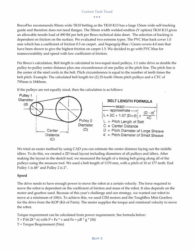
If the pulleys are not equally sized, then the calculation is as follows:
We tried an easier method by using CAD you can estimate the center distance laying out the middle
idlers. To do this, we created a 2D tread layout including diameters of all pulleys and idlers. After
making the layout in the sketch tool, we measured the length of a timing belt going along all of the
pulleys using the measure tool. We used a belt length of 1170 mm, with a pitch of 10 at 177 teeth. End
Pulley 1 is 48” and Pulley 2 is 2”.
Speed
The drive needs to have enough power to move the robot at a certain velocity. The force required to
move the robot is dependent on the coefficient of friction and mass of the robot. It also depends on the
motor and gearbox used. Because of this year’s challenge and our strategy, we wanted our robot to
move at a minimum of 10ft/s. To achieve this, we used CIM motors and the ToughBox Mini Gearbox
for the drive from the KOP (Kit of Parts). The motor supplies the torque and rotational velocity to move
the robot.
Torque requirement can be calculated from power requirement. See formula below:
T = P/(6.28 * n) with P = Fe * v and Fe = μR * g * (M)
T = Torque Requirement (Nm)

Custom Tank Tread
Beri 4
P = Power Requirement (Watt)
Fe = Effective Force (N)
v = Velocity (m/s)
μR = Coefficient of friction
g = gravity (m/s)
M = Material weight (kg)
M =Weight of robot = 120 lbs max=54.5 kg
Fe =Force=0.5*9.81*(54.5) = 267N
Watts to torque conversion can be mathematically derived from the below formula Torque=Power/2*3.14* rotational velocity=Force*velocity/ (6.28*n) For a CIM motor, the free speed is 5310 rpm, and a stall torque of 2.43 Nm. Using half of free speed,
2655 rpm, 2655*2π/60=278 rad/s. Velocity requirement of 10feet/s or 3m/s. Torque= 267*3/(6.28*278*60)=
0.008 Nm.
Materials
Materials play an important role in design in keeping the robot light. It is important to select the right
material for the property required. Plastics are a good choice over metal in keeping weight low as long
as you can get the required properties. Below is a comparison of materials that can be used.
Density g/cc Properties Cost Application
Polycarbonate 1.2 Light, strength Low Frame for the tank tread
Delrin (Acetal) ≥1.4 Low coefficient of friction Low Idlers, Spacers
Carbon Fiber 1.8 Strongest material High Braces to support
Aluminum 2.7 Light weight metal, easy to
machine
Medium Pulley and center frame,
attachment bolts
Build Process
The first step was to water jet the polycarbonate frame. Then we glued them with Loctite epoxy
“Loctite 352” and used an oven at 250 °F to set for 1 hour. Once set, we attached the pulleys and wheels
on the frame. Then we mounted the gear box, finished wiring and put the belts on. More details of the
build are available in the technical book for Stomgears 5422.

Custom Tank Tread
Beri 5
Many thanks to the mentors who helped us understand the engineering principles. And my team 5422,
together we built the drive in less than 6 weeks.
References: Brecoflex Data Sheet, McMaster Carr Data Sheet, Motor Performance Presentation WPI