Embed Size (px)
Citation preview

Custom Tray Fittings
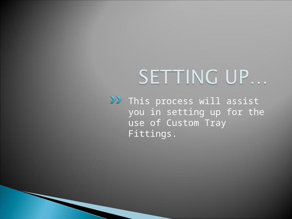
This process will assist you in setting up for the use of Custom Tray Fittings.
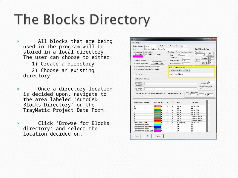
o All blocks that are being used in the program will be stored in a local directory. The user can choose to either:
1) Create a directory 2) Choose an existing directory
o Once a directory location is decided upon, navigate to the area labeled ‘AutoCAD Blocks Directory’ on the TrayMatic Project Data Form.
o Click ‘Browse for Blocks directory’ and select the location decided on.
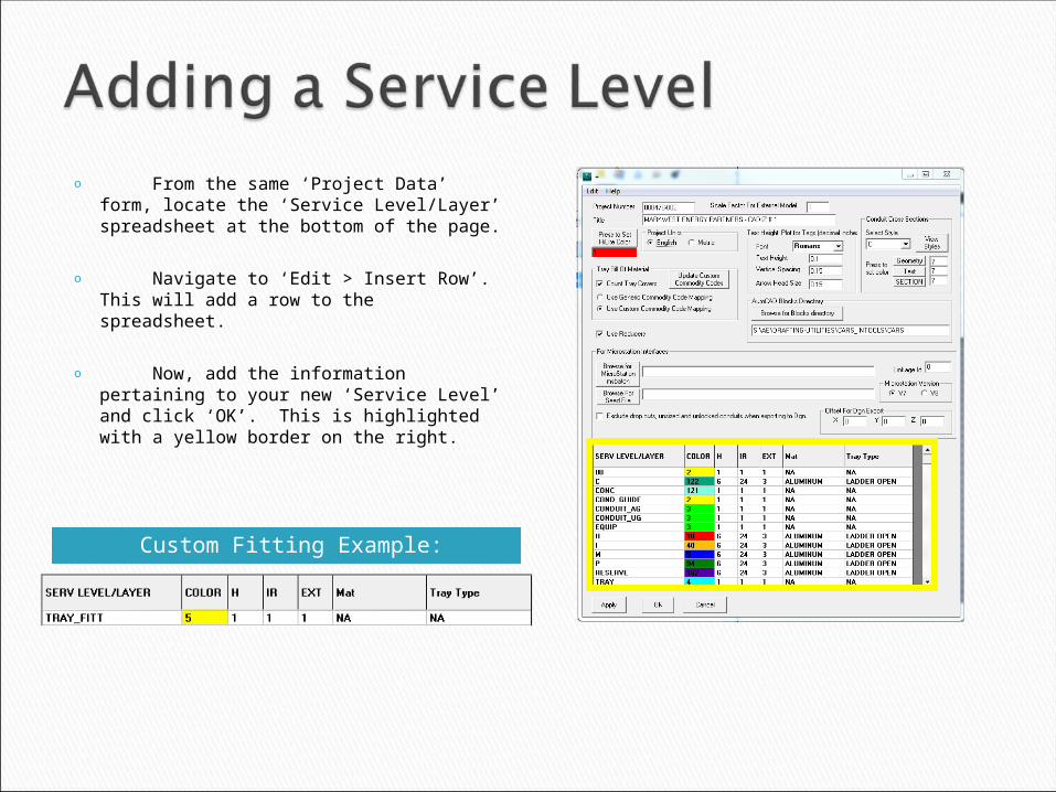
Custom Fitting Example:
o From the same ‘Project Data’ form, locate the ‘Service Level/Layer’ spreadsheet at the bottom of the page.
o Navigate to ‘Edit > Insert Row’. This will add a row to the spreadsheet.
o Now, add the information pertaining to your new ‘Service Level’ and click ‘OK’. This is highlighted with a yellow border on the right.

Populating the list of selectable blocks to be used during design.

o On the Tail-End tab of TrayMatic, towards the bottom of the form, there is a drop down style box.
o By clicking the arrow on the right side of the box, a list of possible selections for that particular dropdown will appear. This functionality is depicted on the right.
Continued on next slide…
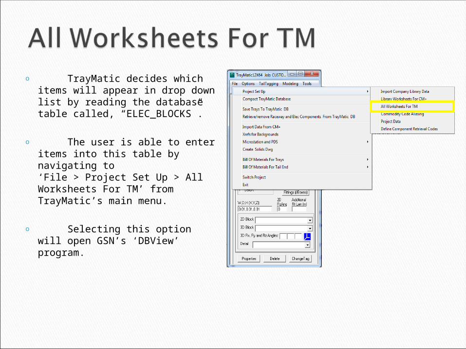
o TrayMatic decides which items will appear in drop down list by reading the database table called, “ELEC_BLOCKS”.
o The user is able to enter items into this table by navigating to ‘File > Project Set Up > All Worksheets For TM’ from TrayMatic’s main menu.
o Selecting this option will open GSN’s ‘DBView’ program.
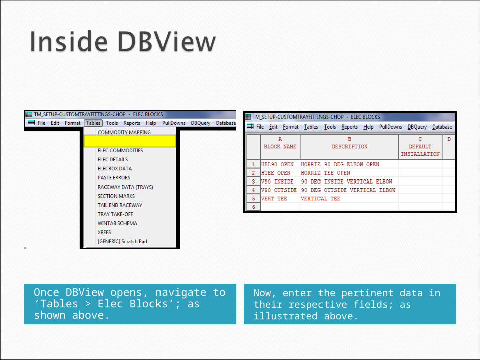
Once DBView opens, navigate to ‘Tables > Elec Blocks’; as shown above.
Now, enter the pertinent data in their respective fields; as illustrated above.
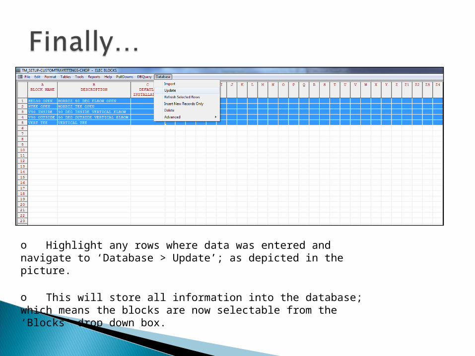
o Highlight any rows where data was entered and navigate to ‘Database > Update’; as depicted in the picture.
o This will store all information into the database; which means the blocks are now selectable from the ‘Blocks’ drop down box.

The following slides will illustrate the method to use blocks to perform tray routing.

**Note: Cable tray centerlines should always be drawn to the
bottom of the tray (BOT).
Click the video to start it.
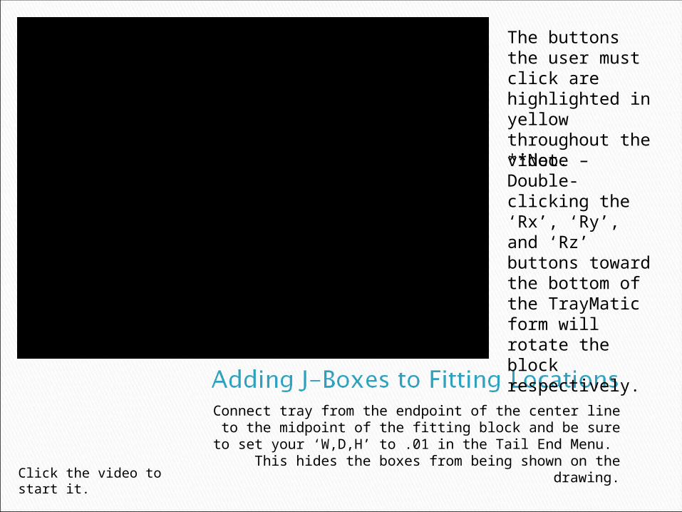
Connect tray from the endpoint of the center line to the midpoint of the fitting block and be sure to set
your ‘W,D,H’ to .01 in the Tail End Menu. This hides the boxes from being shown on the drawing.Click the video to start
it.
The buttons the user must click are highlighted in yellow throughout the video.**Note – Double-clicking the ‘Rx’, ‘Ry’, and ‘Rz’ buttons toward the bottom of the TrayMatic form will rotate the block respectively.

Draw tray segments from fitting to fitting.
Click the video to start it.
Airways will be drawn as shown in the video or from end point of tray segment to end point of tray segment. This will allow for cable to be
routed through the tray design.
When finished, name your tray by whatever method desired and delete the centerlines created at the beginning of the process.Click the video to start
it.

After Custom Tray Fittings Are created and saved to the database, they can be retrieved at any time using standard GSN Techniques.
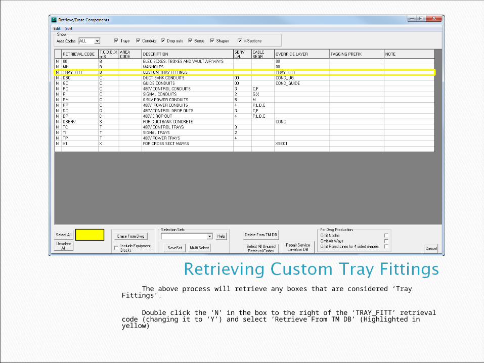
The above process will retrieve any boxes that are considered ‘Tray Fittings’. Double click the ‘N’ in the box to the right of the ‘TRAY_FITT’ retrieval code (changing it to ‘Y’) and select ‘Retrieve From TM DB’ (Highlighted in yellow)
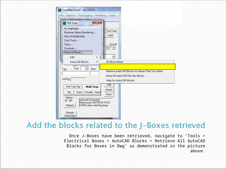
Once J-Boxes have been retrieved, navigate to ‘Tools > Electrical Boxes > AutoCAD Blocks > Retrieve All AutoCAD
Blocks for Boxes in Dwg’ as demonstrated in the picture above.

The following slides will illustrate the differences in the processes required to produce a Bill of Materials based on custom tray fittings in the drawing.
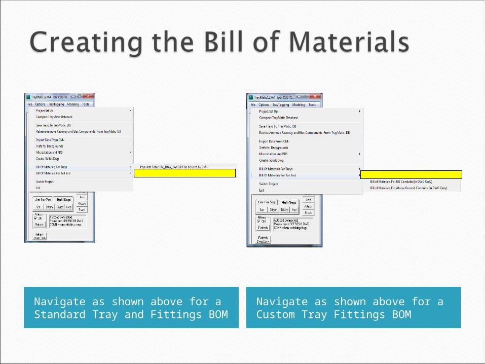
Navigate as shown above for a Standard Tray and Fittings BOM
Navigate as shown above for a Custom Tray Fittings BOM
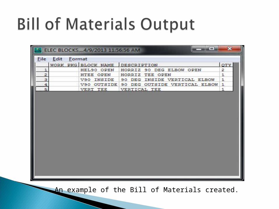
An example of the Bill of Materials created.

If all of the steps in this outline were followed, you now have a tray system designed with custom tray fittings, cable routing functionality, and an accurate Bill of Materials. For additional questions or comments, please contact the GSN Office at (678) 831-0725.
Thank you.