Embed Size (px)
Citation preview
1 © 2015 ANSYS, Inc. November 12, 2015 ANSYS Confidential
Customer Application Presentation
ANSYS Solution for PCB Reliability
Ankit Adhiya
Vamsi Krishna
Rohit Patchigolla
2 © 2015 ANSYS, Inc. November 12, 2015 ANSYS Confidential
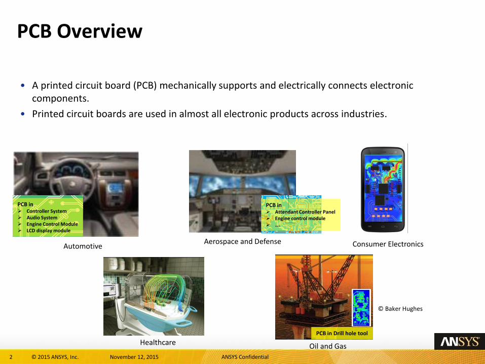
PCB Overview
• A printed circuit board (PCB) mechanically supports and electrically connects electronic components.
• Printed circuit boards are used in almost all electronic products across industries.
Aerospace and Defense Consumer Electronics Automotive
Healthcare Oil and Gas
PCB in Controller System Audio System Engine Control Module LCD display module
PCB in Drill hole tool
© Baker Hughes
PCB in Attendant Controller Panel Engine control module ….
3 © 2015 ANSYS, Inc. November 12, 2015 ANSYS Confidential
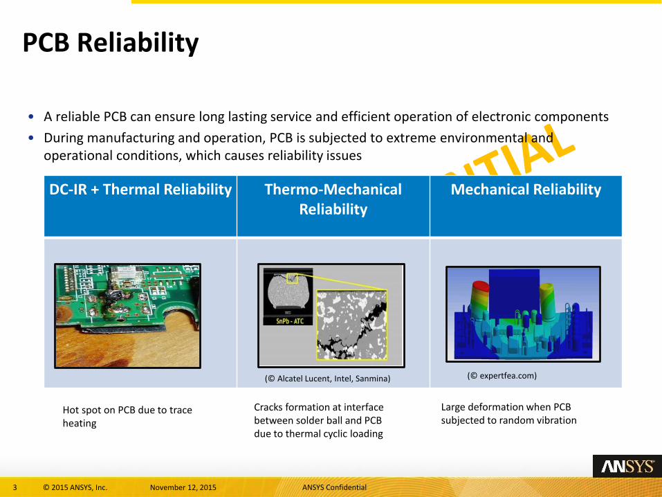
DC-IR + Thermal Reliability Thermo-Mechanical Reliability
Mechanical Reliability
PCB Reliability
Large deformation when PCB subjected to random vibration
Cracks formation at interface between solder ball and PCB due to thermal cyclic loading
Hot spot on PCB due to trace heating
(© Alcatel Lucent, Intel, Sanmina) (© expertfea.com)
• A reliable PCB can ensure long lasting service and efficient operation of electronic components
• During manufacturing and operation, PCB is subjected to extreme environmental and operational conditions, which causes reliability issues
4 © 2015 ANSYS, Inc. November 12, 2015 ANSYS Confidential
Content
• DC-IR + Thermal Reliability
• Thermo-Mechanical Reliability
• Mechanical Reliability
5 © 2015 ANSYS, Inc. November 12, 2015 ANSYS Confidential
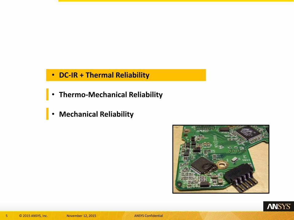
• DC-IR + Thermal Reliability
• Thermo-Mechanical Reliability
• Mechanical Reliability

6 © 2015 ANSYS, Inc. November 12, 2015 ANSYS Confidential
Background : Joule Heating
• What is Joule Heating?
• Joule heating / resistive heating is the process by which the passage of
electric current ( 𝐼 ) through a conductor of electrical resistance ( 𝑅 )
releases heat ( 𝑄 )
𝑄 = 𝐼2𝑅
• Why do we need to perform thermal reliability analysis on printed circuit / wiring boards?
• High current PCB’s are densely populated with components
• Reduction of trace and via dimensions
• Current densities increase
• Joule heating effects on copper traces Temperatures increase Reliability issues
PCB delamination and failure
7 © 2015 ANSYS, Inc. November 12, 2015 ANSYS Confidential
ANSYS Solution
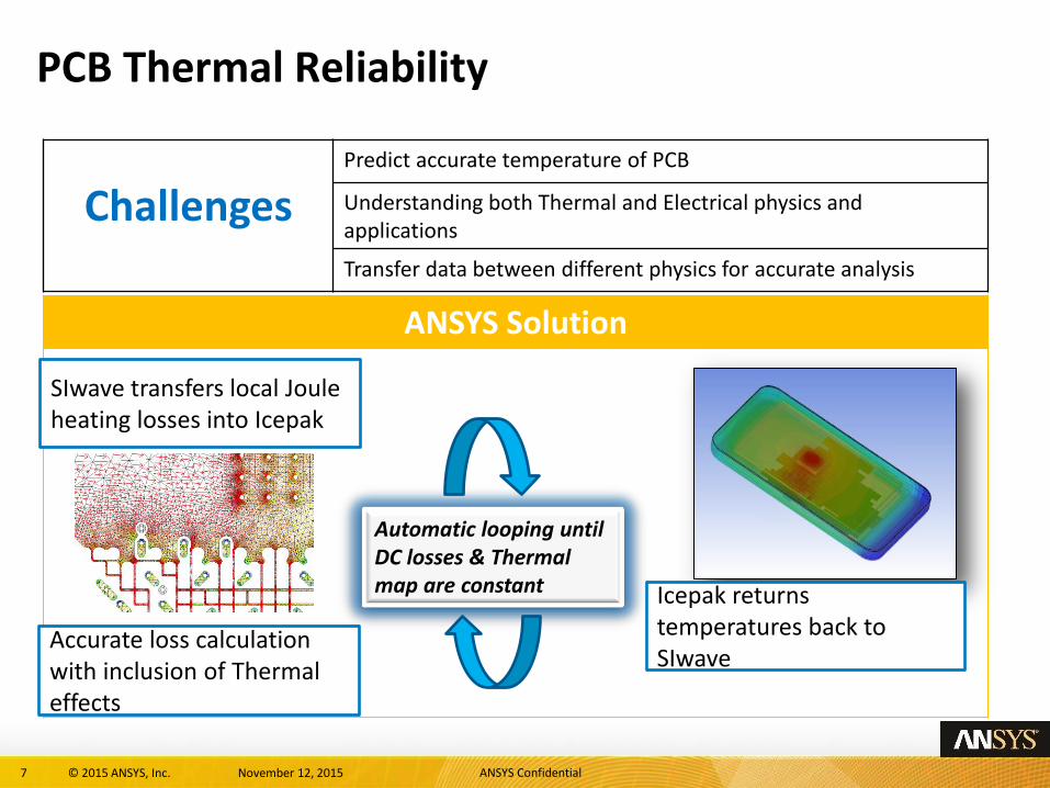
PCB Thermal Reliability
Challenges Predict accurate temperature of PCB
Understanding both Thermal and Electrical physics and applications
Transfer data between different physics for accurate analysis
Accurate loss calculation with inclusion of Thermal effects
Automatic looping until DC losses & Thermal map are constant
SIwave transfers local Joule heating losses into Icepak
Icepak returns temperatures back to SIwave
8 © 2015 ANSYS, Inc. November 12, 2015 ANSYS Confidential
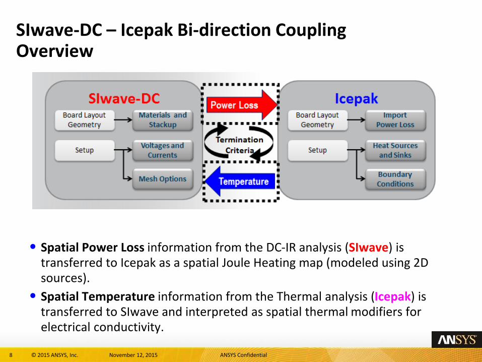
• Spatial Power Loss information from the DC-IR analysis (SIwave) is transferred to Icepak as a spatial Joule Heating map (modeled using 2D sources).
• Spatial Temperature information from the Thermal analysis (Icepak) is transferred to SIwave and interpreted as spatial thermal modifiers for electrical conductivity.
SIwave-DC – Icepak Bi-direction Coupling Overview
9 © 2015 ANSYS, Inc. November 12, 2015 ANSYS Confidential
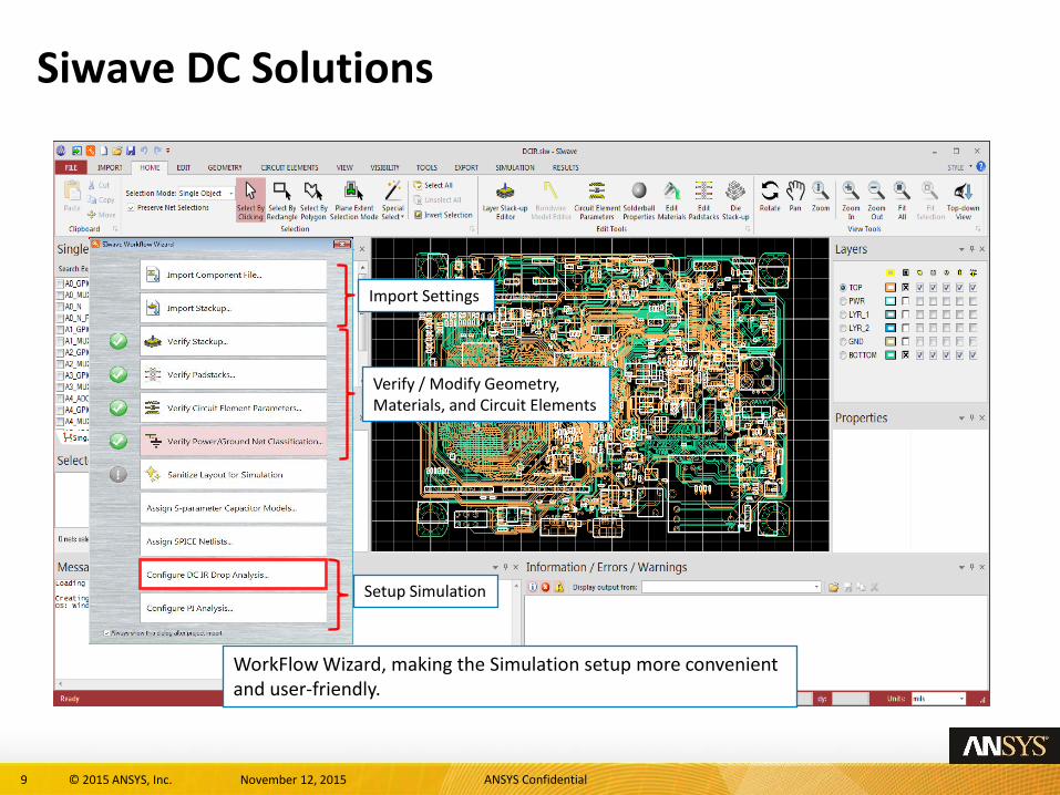
Siwave DC Solutions
WorkFlow Wizard, making the Simulation setup more convenient and user-friendly.
Import Settings
Verify / Modify Geometry, Materials, and Circuit Elements
Setup Simulation
10 © 2015 ANSYS, Inc. November 12, 2015 ANSYS Confidential
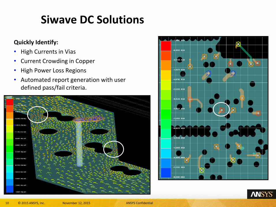
Siwave DC Solutions
Quickly Identify:
• High Currents in Vias
• Current Crowding in Copper
• High Power Loss Regions
• Automated report generation with user defined pass/fail criteria.
11 © 2015 ANSYS, Inc. November 12, 2015 ANSYS Confidential
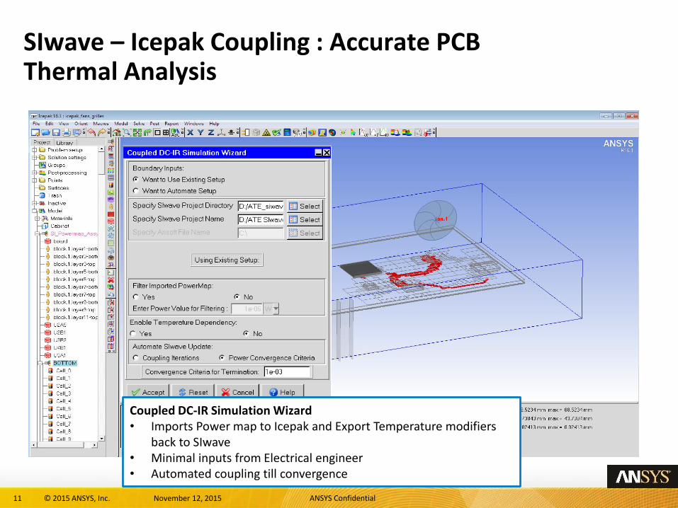
SIwave – Icepak Coupling : Accurate PCB Thermal Analysis
Coupled DC-IR Simulation Wizard • Imports Power map to Icepak and Export Temperature modifiers
back to SIwave • Minimal inputs from Electrical engineer • Automated coupling till convergence
12 © 2015 ANSYS, Inc. November 12, 2015 ANSYS Confidential
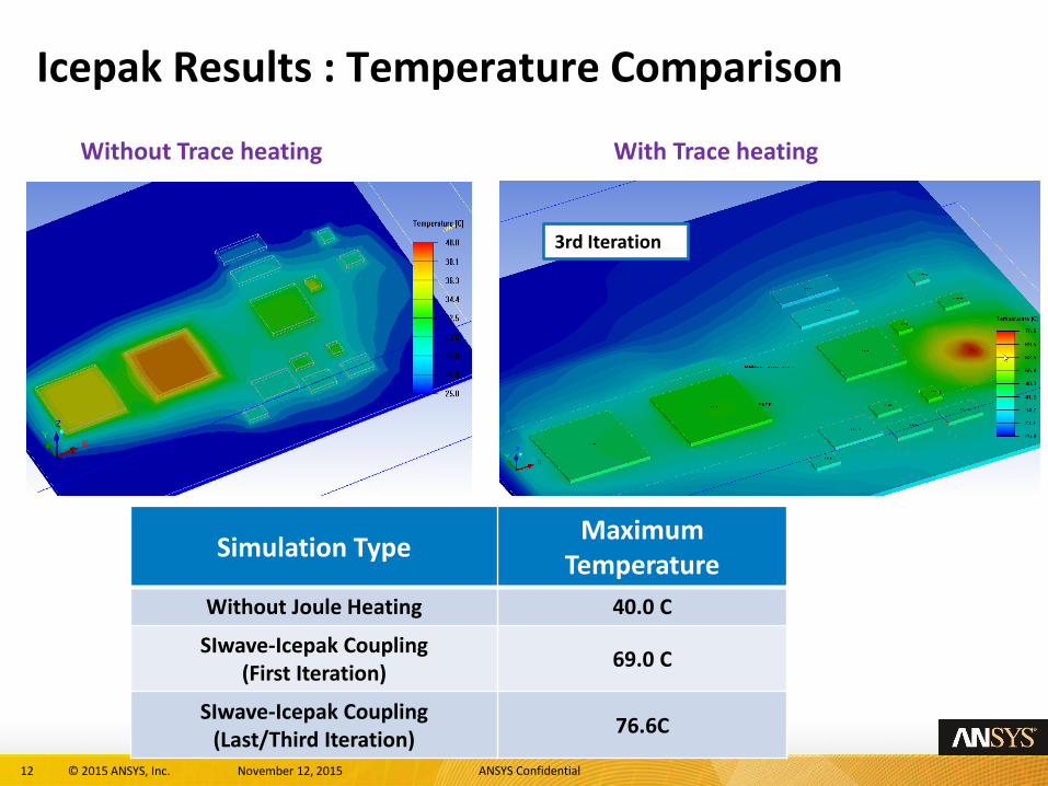
Icepak Results : Temperature Comparison
Without Trace heating With Trace heating
Simulation Type Maximum
Temperature
Without Joule Heating 40.0 C
SIwave-Icepak Coupling (First Iteration)
69.0 C
SIwave-Icepak Coupling (Last/Third Iteration)
76.6C
1st Iteration 2nd Iteration 3rd Iteration
13 © 2015 ANSYS, Inc. November 12, 2015 ANSYS Confidential
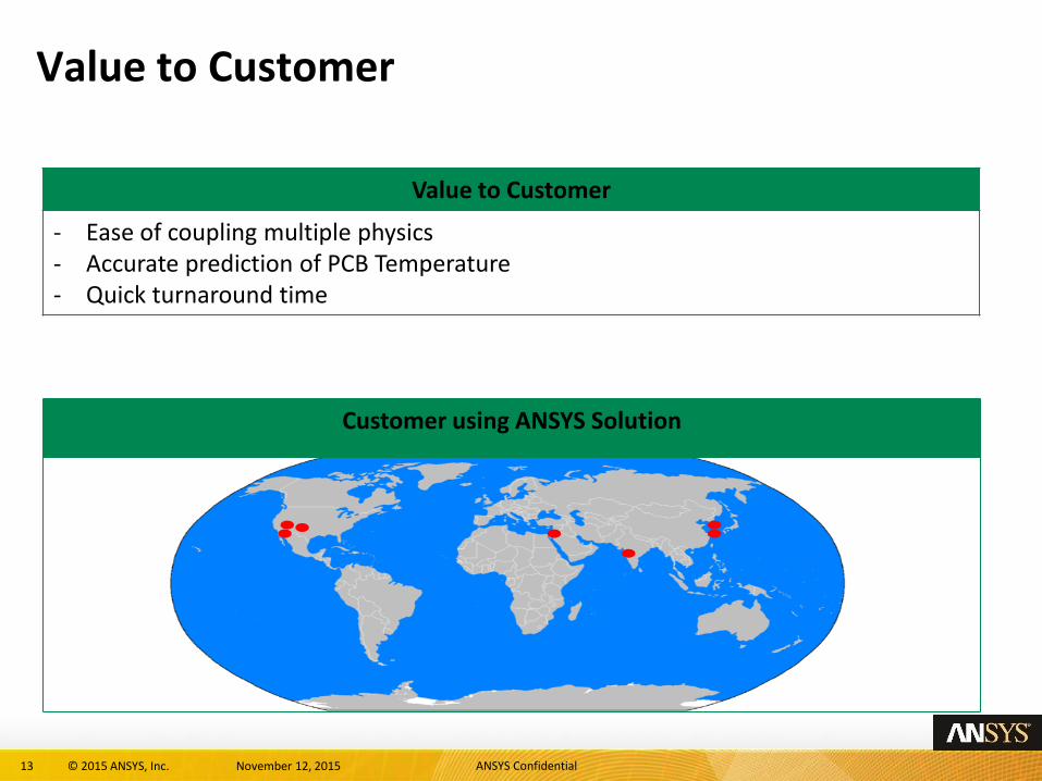
Value to Customer
Value to Customer
- Ease of coupling multiple physics - Accurate prediction of PCB Temperature - Quick turnaround time
Customer using ANSYS Solution
14 © 2015 ANSYS, Inc. November 12, 2015 ANSYS Confidential
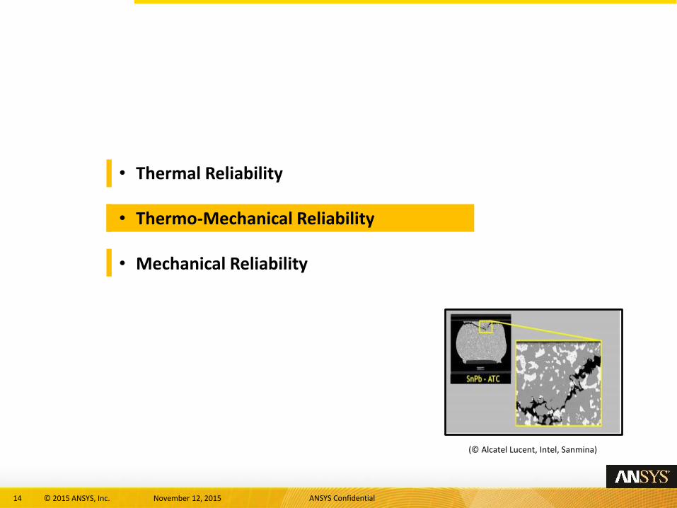
• Thermal Reliability
• Thermo-Mechanical Reliability
• Mechanical Reliability
(© Alcatel Lucent, Intel, Sanmina)
15 © 2015 ANSYS, Inc. November 12, 2015 ANSYS Confidential
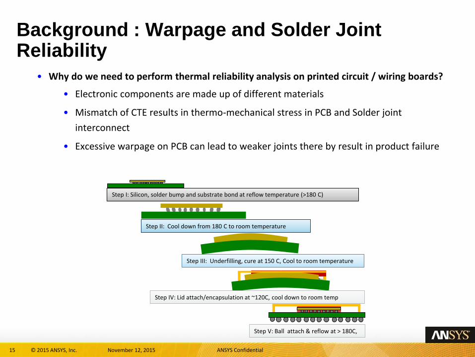
Background : Warpage and Solder Joint Reliability
• Why do we need to perform thermal reliability analysis on printed circuit / wiring boards?
• Electronic components are made up of different materials
• Mismatch of CTE results in thermo-mechanical stress in PCB and Solder joint
interconnect
• Excessive warpage on PCB can lead to weaker joints there by result in product failure
Step I: Silicon, solder bump and substrate bond at reflow temperature (>180 C)
Step II: Cool down from 180 C to room temperature
Step III: Underfilling, cure at 150 C, Cool to room temperature
Step IV: Lid attach/encapsulation at ~120C, cool down to room temp
Step V: Ball attach & reflow at > 180C,
16 © 2015 ANSYS, Inc. November 12, 2015 ANSYS Confidential
ANSYS Solution
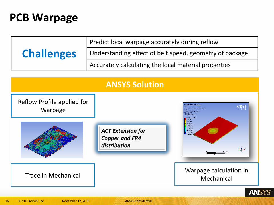
PCB Warpage
Challenges Predict local warpage accurately during reflow
Understanding effect of belt speed, geometry of package
Accurately calculating the local material properties
Trace in Mechanical
ACT Extension for Copper and FR4 distribution
Reflow Profile applied for Warpage
Warpage calculation in Mechanical
17 © 2015 ANSYS, Inc. November 12, 2015 ANSYS Confidential
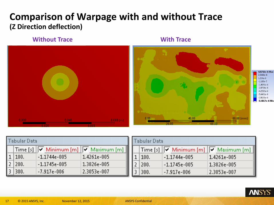
Comparison of Warpage with and without Trace (Z Direction deflection)
Without Trace With Trace
18 © 2015 ANSYS, Inc. November 12, 2015 ANSYS Confidential
ANSYS Solution
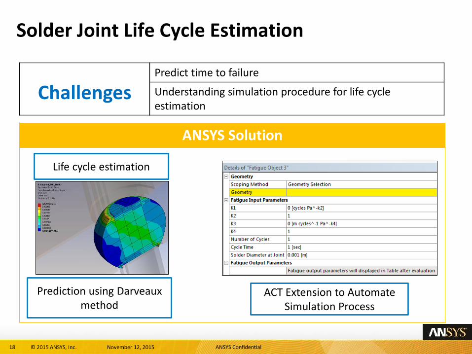
Solder Joint Life Cycle Estimation
Challenges Predict time to failure
Understanding simulation procedure for life cycle estimation
Prediction using Darveaux method
Life cycle estimation
ACT Extension to Automate Simulation Process
19 © 2015 ANSYS, Inc. November 12, 2015 ANSYS Confidential
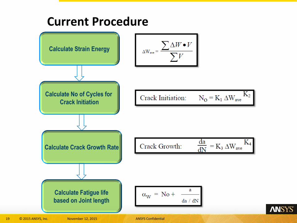
Current Procedure
Calculate Strain Energy
Calculate No of Cycles for
Crack Initiation
Calculate Crack Growth Rate
Calculate Fatigue life
based on Joint length
20 © 2015 ANSYS, Inc. November 12, 2015 ANSYS Confidential
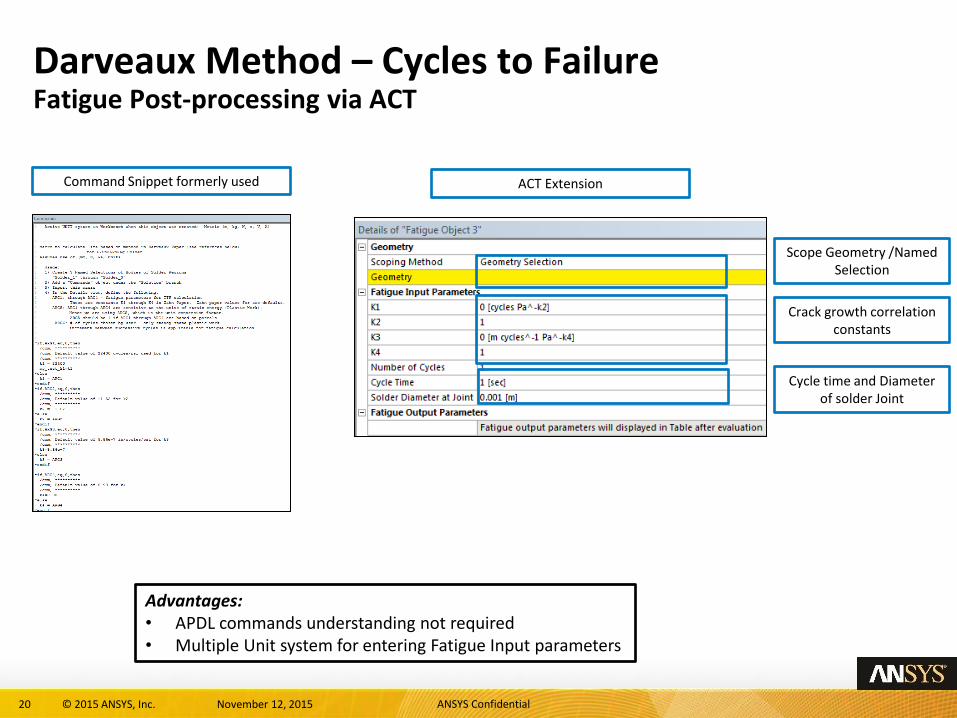
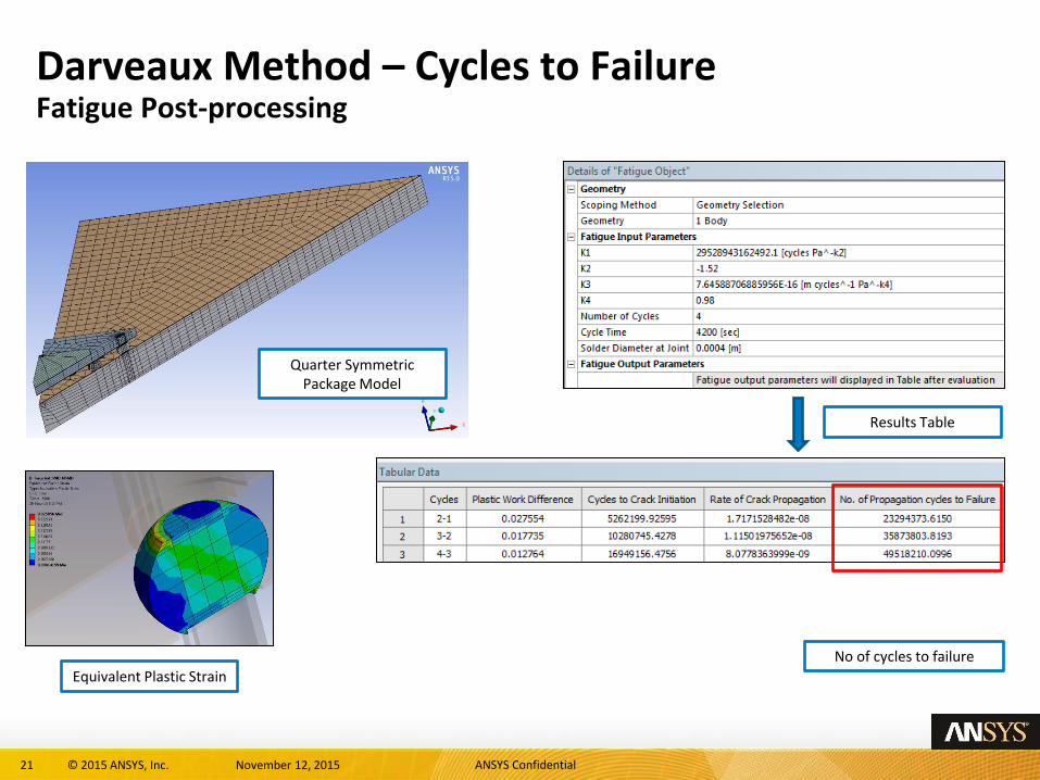
Darveaux Method – Cycles to Failure Fatigue Post-processing via ACT
Scope Geometry /Named Selection
Command Snippet formerly used
Advantages: • APDL commands understanding not required • Multiple Unit system for entering Fatigue Input parameters
Crack growth correlation constants
Cycle time and Diameter of solder Joint
ACT Extension
21 © 2015 ANSYS, Inc. November 12, 2015 ANSYS Confidential
Darveaux Method – Cycles to Failure Fatigue Post-processing
Results Table
Equivalent Plastic Strain
Quarter Symmetric Package Model
No of cycles to failure
22 © 2015 ANSYS, Inc. November 12, 2015 ANSYS Confidential
Value to Customer
Value to Customer
- Accurate prediction of PCB local material properties - Accurate Deformation, stress and Life prediction - Quick turnaround time
Customer using ANSYS Solution
23 © 2015 ANSYS, Inc. November 12, 2015 ANSYS Confidential
• Thermal Reliability
• Thermo-Mechanical Reliability
• Mechanical Reliability
(© expertfea.com)
24 © 2015 ANSYS, Inc. November 12, 2015 ANSYS Confidential
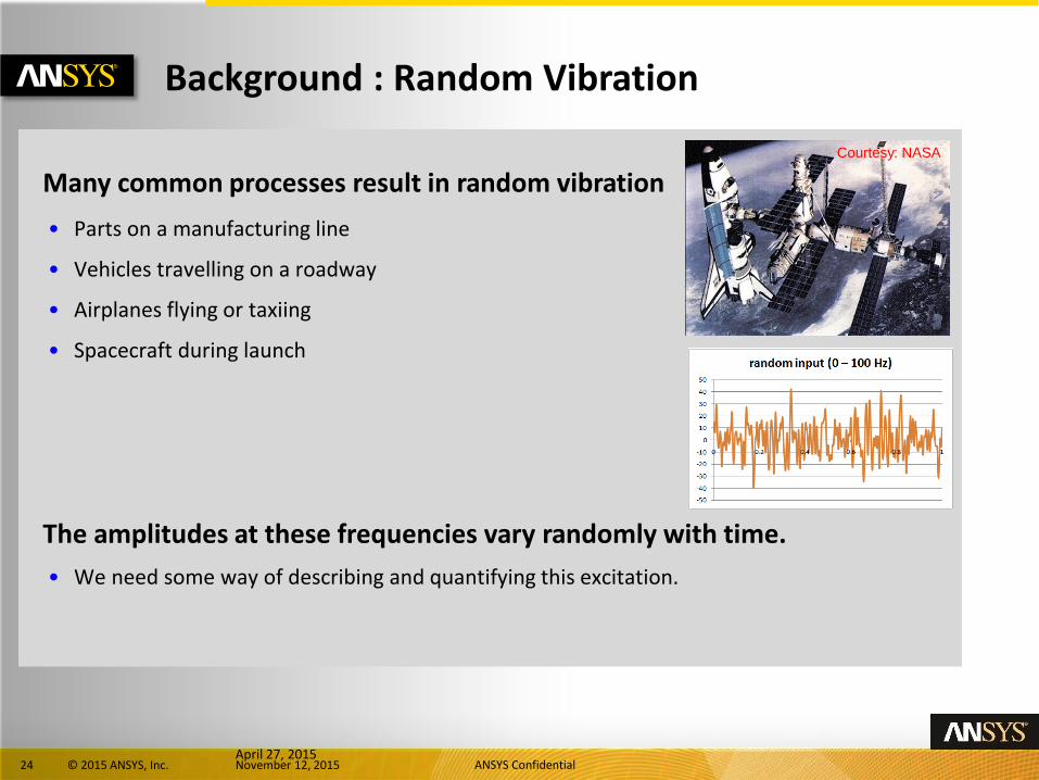
Background : Random Vibration
Many common processes result in random vibration • Parts on a manufacturing line
• Vehicles travelling on a roadway
• Airplanes flying or taxiing
• Spacecraft during launch
Courtesy: NASA
The amplitudes at these frequencies vary randomly with time. • We need some way of describing and quantifying this excitation.
April 27, 2015
25 © 2015 ANSYS, Inc. November 12, 2015 ANSYS Confidential
Background : Random Vibration
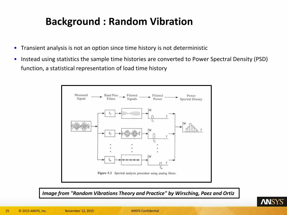
• Transient analysis is not an option since time history is not deterministic
• Instead using statistics the sample time histories are converted to Power Spectral Density (PSD)
function, a statistical representation of load time history
Image from "Random Vibrations Theory and Practice" by Wirsching, Paez and Ortiz
26 © 2015 ANSYS, Inc. November 12, 2015 ANSYS Confidential
ANSYS Solution
PCB Mechanical Reliability
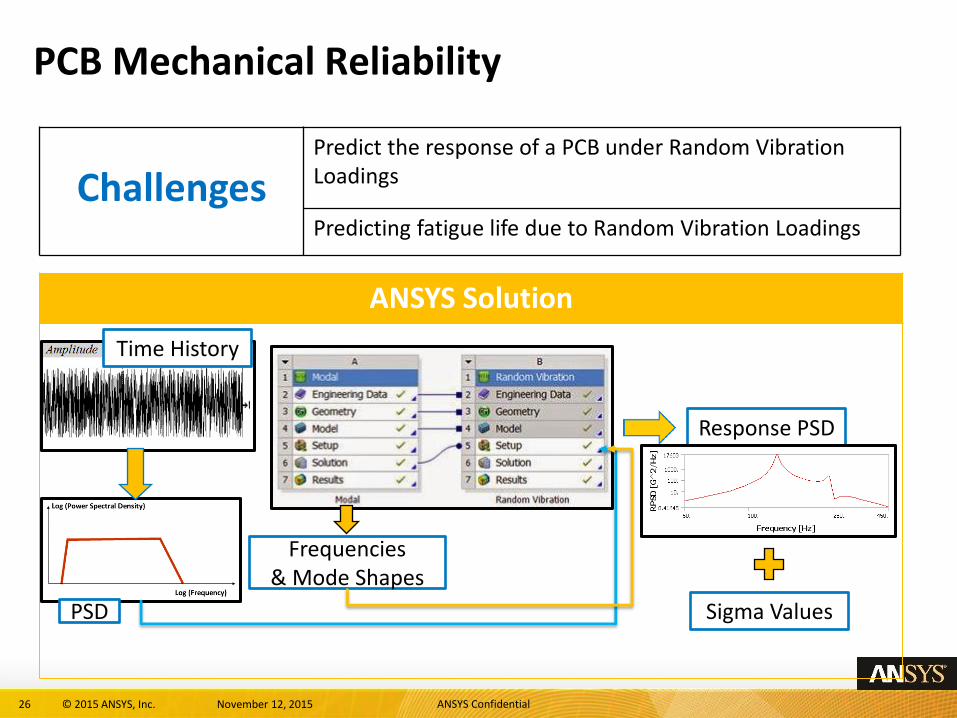
Challenges Predict the response of a PCB under Random Vibration Loadings
Predicting fatigue life due to Random Vibration Loadings
PSD
Time History
Frequencies & Mode Shapes
Response PSD
Sigma Values
27 © 2015 ANSYS, Inc. November 12, 2015 ANSYS Confidential
Assumptions & Restrictions
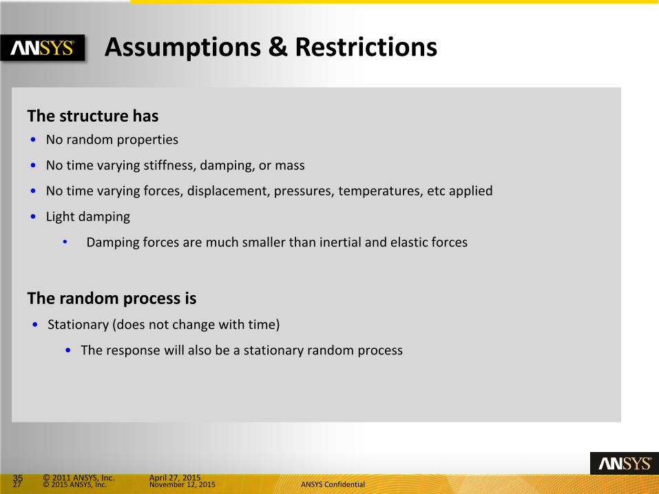
The structure has • No random properties
• No time varying stiffness, damping, or mass
• No time varying forces, displacement, pressures, temperatures, etc applied
• Light damping
• Damping forces are much smaller than inertial and elastic forces
The random process is
• Stationary (does not change with time)
• The response will also be a stationary random process
35 © 2011 ANSYS, Inc. April 27, 2015
28 © 2015 ANSYS, Inc. November 12, 2015 ANSYS Confidential
General Procedure Overview
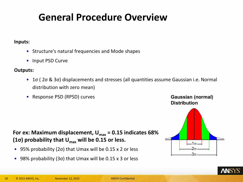
Inputs:
• Structure's natural frequencies and Mode shapes
• Input PSD Curve
Outputs:
• 1σ ( 2σ & 3σ) displacements and stresses (all quantities assume Gaussian i.e. Normal
distribution with zero mean)
• Response PSD (RPSD) curves
For ex: Maximum displacement, Umax = 0.15 indicates 68% (1σ) probability that Umax will be 0.15 or less.
• 95% probability (2σ) that Umax will be 0.15 x 2 or less
• 98% probability (3σ) that Umax will be 0.15 x 3 or less
29 © 2015 ANSYS, Inc. November 12, 2015 ANSYS Confidential
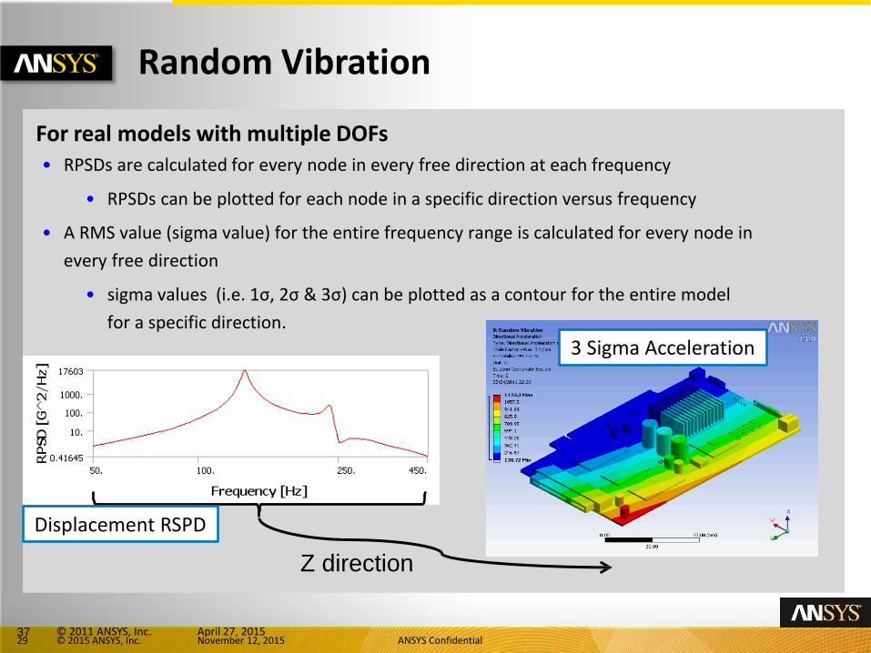
Random Vibration For real models with multiple DOFs • RPSDs are calculated for every node in every free direction at each frequency
• RPSDs can be plotted for each node in a specific direction versus frequency
• A RMS value (sigma value) for the entire frequency range is calculated for every node in
every free direction
• sigma values (i.e. 1σ, 2σ & 3σ) can be plotted as a contour for the entire model
for a specific direction.
Z direction
37 © 2011 ANSYS, Inc. April 27, 2015
3 Sigma Acceleration
Displacement RSPD
30 © 2015 ANSYS, Inc. November 12, 2015 ANSYS Confidential
Value to Customer
Value to Customer
- Accurate prediction of behavior of an electronic component under random vibrational loadings
- Quick turnaround time
Customer using ANSYS Solution
31 © 2015 ANSYS, Inc. November 12, 2015 ANSYS Confidential
Summary
• ANSYS Solution helps to predict reliability for different analysis in a PCB lifecycle
• Automation scripts and customization makes it easy to simulate all the interconnected analysis
• Simulation driven product development allows
• Quick turn around time and
• Reduced time to market
32 © 2015 ANSYS, Inc. November 12, 2015 ANSYS Confidential
• The slides with watermark of “ANSYS Confidential” should be removed before showing/sharing this document externally
• The author (or uploader) and the reviewer of this document have, to the best of their knowledge, identified the source of various images, animations, text, plots etc. and classified them based on “Restrictions for Use” type. Kindly review the section on “Reference” at the end of this document.
• All Customer Application Presentations are marked as “For Internal Use only” by default since it might contain
• Use your judgement on how this document can be shared
Instructions on Usage of this Document
33 © 2015 ANSYS, Inc. November 12, 2015 ANSYS Confidential
Use this slide for any “ANSYS Confidential” Content
34 © 2015 ANSYS, Inc. November 12, 2015 ANSYS Confidential
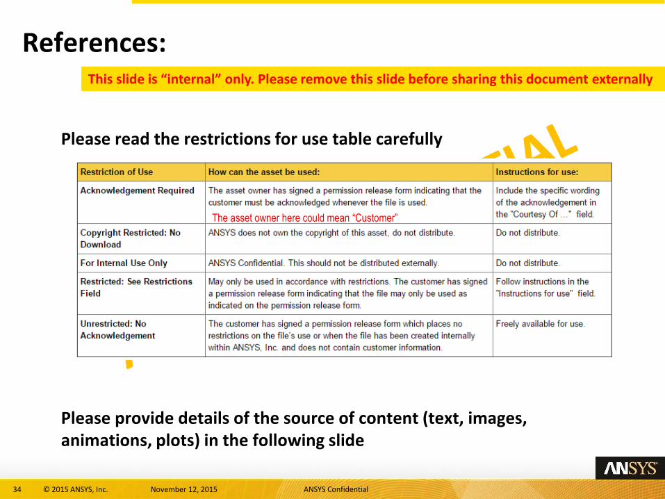
References: This slide is “internal” only. Please remove this slide before sharing this document externally
Please read the restrictions for use table carefully
Please provide details of the source of content (text, images, animations, plots) in the following slide
The asset owner here could mean “Customer”
35 © 2015 ANSYS, Inc. November 12, 2015 ANSYS Confidential
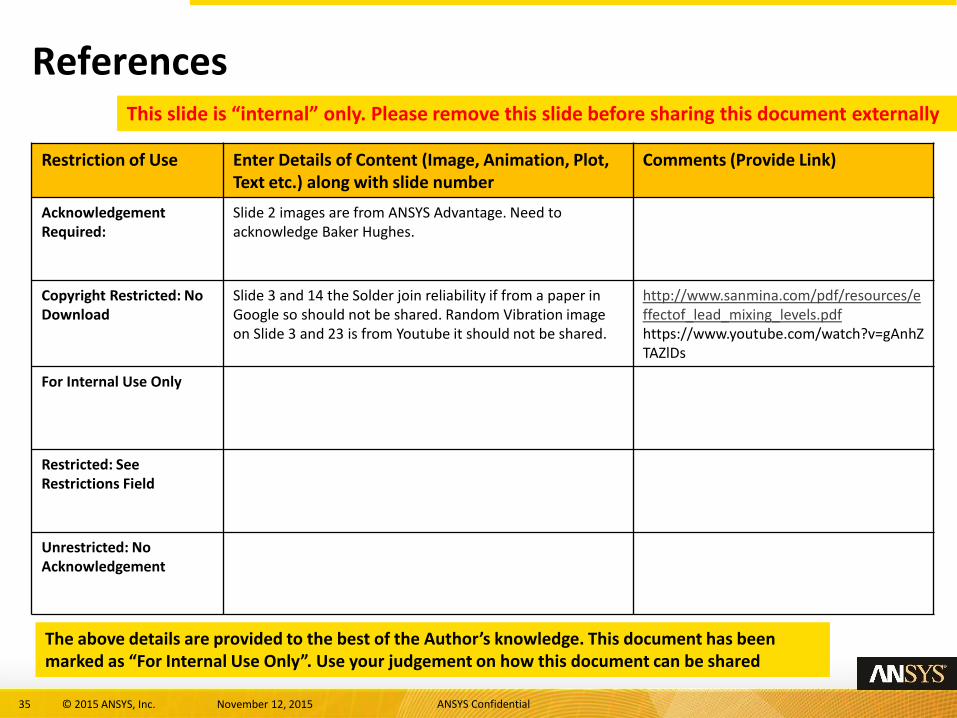
References
Restriction of Use Enter Details of Content (Image, Animation, Plot, Text etc.) along with slide number
Comments (Provide Link)
Acknowledgement Required:
Slide 2 images are from ANSYS Advantage. Need to acknowledge Baker Hughes.
Copyright Restricted: No Download
Slide 3 and 14 the Solder join reliability if from a paper in Google so should not be shared. Random Vibration image on Slide 3 and 23 is from Youtube it should not be shared.
http://www.sanmina.com/pdf/resources/effectof_lead_mixing_levels.pdf https://www.youtube.com/watch?v=gAnhZTAZlDs
For Internal Use Only
Restricted: See Restrictions Field
Unrestricted: No Acknowledgement
This slide is “internal” only. Please remove this slide before sharing this document externally
The above details are provided to the best of the Author’s knowledge. This document has been marked as “For Internal Use Only”. Use your judgement on how this document can be shared