Embed Size (px)
Citation preview
StorageTek SL150 Modular Tape LibraryCustomer Replaceable Unit Guide
E29812-08
April 2014

StorageTek SL150 Modular Tape Library Customer Replaceable Unit Guide
E29812-08
Copyright © 2012, 2014, Oracle and/or its affiliates. All rights reserved.
This software and related documentation are provided under a license agreement containing restrictions onuse and disclosure and are protected by intellectual property laws. Except as expressly permitted in yourlicense agreement or allowed by law, you may not use, copy, reproduce, translate, broadcast, modify, license,transmit, distribute, exhibit, perform, publish, or display any part, in any form, or by any means. Reverseengineering, disassembly, or decompilation of this software, unless required by law for interoperability, isprohibited.
The information contained herein is subject to change without notice and is not warranted to be error-free. Ifyou find any errors, please report them to us in writing.
If this is software or related documentation that is delivered to the U.S. Government or anyone licensing iton behalf of the U.S. Government, the following notice is applicable:
U.S. GOVERNMENT END USERS: Oracle programs, including any operating system, integrated software,any programs installed on the hardware, and/or documentation, delivered to U.S. Government end usersare "commercial computer software" pursuant to the applicable Federal Acquisition Regulation andagency-specific supplemental regulations. As such, use, duplication, disclosure, modification, andadaptation of the programs, including any operating system, integrated software, any programs installed onthe hardware, and/or documentation, shall be subject to license terms and license restrictions applicable tothe programs. No other rights are granted to the U.S. Government.
This software or hardware is developed for general use in a variety of information managementapplications. It is not developed or intended for use in any inherently dangerous applications, includingapplications that may create a risk of personal injury. If you use this software or hardware in dangerousapplications, then you shall be responsible to take all appropriate fail-safe, backup, redundancy, and othermeasures to ensure its safe use. Oracle Corporation and its affiliates disclaim any liability for any damagescaused by use of this software or hardware in dangerous applications.
Oracle and Java are registered trademarks of Oracle and/or its affiliates. Other names may be trademarks oftheir respective owners.
Intel and Intel Xeon are trademarks or registered trademarks of Intel Corporation. All SPARC trademarksare used under license and are trademarks or registered trademarks of SPARC International, Inc. AMD,Opteron, the AMD logo, and the AMD Opteron logo are trademarks or registered trademarks of AdvancedMicro Devices. UNIX is a registered trademark of The Open Group.
This software or hardware and documentation may provide access to or information on content, products,and services from third parties. Oracle Corporation and its affiliates are not responsible for and expresslydisclaim all warranties of any kind with respect to third-party content, products, and services. OracleCorporation and its affiliates will not be responsible for any loss, costs, or damages incurred due to youraccess to or use of third-party content, products, or services.
iii
Contents
Preface ................................................................................................................................................................ vii
Documentation Accessibility .................................................................................................................... vii
1 Product Overview
General Information ................................................................................................................................ 1-1Class 1 Laser Product Notice .................................................................................................................. 1-3Library Status Indicators......................................................................................................................... 1-3Customer Replaceable Units .................................................................................................................. 1-4
CRU Indicators and Controls ........................................................................................................... 1-4
2 Preparations
Electrostatic Discharge ............................................................................................................................ 2-1Electrostatic Discharge Prevention.................................................................................................. 2-1Grounding Methods to Prevent Electrostatic Discharge.............................................................. 2-1
SL150 Remote Interface........................................................................................................................... 2-1
3 Removal and Replacement
Problem Determination .......................................................................................................................... 3-1Common Procedures................................................................................................................................ 3-2
To Set the Library Offline.................................................................................................................. 3-2To Set the Library Online .................................................................................................................. 3-3To Enable the Locate Light ............................................................................................................... 3-3Tape Cartridge Magazine ................................................................................................................. 3-3To Remove a Tape Cartridge Magazine ......................................................................................... 3-4To Replace a Tape Cartridge Magazine .......................................................................................... 3-6
Hot Swappable CRUs ............................................................................................................................. 3-6Drive Tray Assembly......................................................................................................................... 3-6
Bridged Drive Considerations .................................................................................................. 3-7To Remove the Drive Tray................................................................................................................ 3-7To Replace the Drive Tray ................................................................................................................ 3-9Power Supply...................................................................................................................................... 3-9To Remove the Power Supply....................................................................................................... 3-10To Replace the Power Supply........................................................................................................ 3-10
Other CRUs............................................................................................................................................. 3-11Preparation Procedures.................................................................................................................. 3-11
iv
Power-Down............................................................................................................................. 3-11To Perform a Controlled Power-Down from the GUI........................................................ 3-11To Perform an Orderly Shutdown from the Front Control Panel .................................... 3-12To Perform a Forced Power-Down ...................................................................................... 3-13To Remove a Cartridge Magazine Manually....................................................................... 3-13
Front Control Panel......................................................................................................................... 3-14To Remove the Front Control Panel ............................................................................................. 3-15To Replace the Front Control Panel.............................................................................................. 3-16Module Controller........................................................................................................................... 3-16To Remove the Module Controller............................................................................................... 3-17To Replace the Module Controller................................................................................................ 3-18Robot Module .................................................................................................................................. 3-18To Remove the Robot ..................................................................................................................... 3-18To Manually Retract the Robot .................................................................................................... 3-20To Manually Disengage the Robot ............................................................................................... 3-21To Replace the Robot ...................................................................................................................... 3-22Expansion Module Chassis............................................................................................................ 3-23To Remove an Expansion Module................................................................................................ 3-23
To Remove the Drive Filler..................................................................................................... 3-25To Remove the Power Supply Filler ..................................................................................... 3-26
To Prepare the Expansion CRU for Replacement ...................................................................... 3-27To Install the Floor ......................................................................................................................... 3-27To Replace the Expansion CRU Chassis ...................................................................................... 3-29
To Install the Drive Filler ........................................................................................................ 3-31To Install the Power Supply Filler ......................................................................................... 3-31
Base Module (Module 1) Chassis.................................................................................................. 3-31To Remove the Base Module Chassis........................................................................................... 3-32To Prepare the Base Module CRU for Replacement .................................................................. 3-33To Replace the Base Module Chassis ........................................................................................... 3-33
Power System Behavior........................................................................................................................ 3-35To Power-on the Library ................................................................................................................ 3-35To Validate Library Operation...................................................................................................... 3-36
CRU Return ............................................................................................................................................ 3-37
A Startup
Glossary
Index
v
List of Figures
1–1 StorageTek SL150 Base and Expansion Modules .................................................................. 1-11–2 Remote Management Interface ................................................................................................. 1-21–3 Library Status Indicators (Front Control Panel) ..................................................................... 1-32–1 SL150 Remote Management Log In Dialog............................................................................. 2-23–1 CRU Locations (Rear View of SL150 Base and Expansion Module) ................................... 3-13–2 Set Library Offline....................................................................................................................... 3-23–3 Offline Confirmation .................................................................................................................. 3-23–4 Locate the Library ....................................................................................................................... 3-33–5 Tape Magazine ........................................................................................................................... 3-43–6 Magazine Actions........................................................................................................................ 3-53–7 Magazine Unlock Dialog Box (Code Version 2.25) ................................................................ 3-53–8 Tape Drive Tray CRU................................................................................................................. 3-73–9 Thumbscrews, Latch, and Lock ............................................................................................... 3-83–10 Power Supply CRU.................................................................................................................. 3-103–11 Power Down Library............................................................................................................... 3-123–12 Prepare the Robot for Removal.............................................................................................. 3-123–13 Magazine Release..................................................................................................................... 3-133–14 Rear View of the Front Control Panel ................................................................................... 3-143–15 Front Control Panel Side View............................................................................................... 3-153–16 Front Control Panel Jack ......................................................................................................... 3-153–17 Front Control Panel Slots in Base Module............................................................................ 3-163–18 Module Controller CRU.......................................................................................................... 3-173–19 Robot Removal and Replacement.......................................................................................... 3-193–20 Bullwheel Gear and Robot Lock ............................................................................................ 3-203–21 Robot Lock (Unlocked)............................................................................................................ 3-223–22 Additional Module CRU......................................................................................................... 3-233–23 Library Floor Panel .................................................................................................................. 3-243–24 Module Rear Rail Removal..................................................................................................... 3-253–25 Tape Drive Filler....................................................................................................................... 3-263–26 Power Supply Filler ................................................................................................................. 3-273–27 Floor Tab.................................................................................................................................... 3-283–28 Floor Latching Tab .................................................................................................................. 3-283–29 Avoid Contact with the Operator Panel .............................................................................. 3-293–30 Module Alignment .................................................................................................................. 3-303–31 Base Module CRU.................................................................................................................... 3-313–32 Base Module Side Tabs............................................................................................................ 3-333–33 Cable Attachment .................................................................................................................... 3-343–34 Home Screen............................................................................................................................. 3-36

vi
vii
Preface
This guide is intended for anyone involved with removing and replacing customerreplaceable units (CRUs) in Oracle’s StorageTek SL150 Modular Tape Library.
Documentation AccessibilityFor information about Oracle's commitment to accessibility, visit the OracleAccessibility Program website athttp://www.oracle.com/pls/topic/lookup?ctx=acc&id=docacc.
Access to Oracle SupportOracle customers have access to electronic support through My Oracle Support. Forinformation, visit http://www.oracle.com/pls/topic/lookup?ctx=acc&id=info orvisit http://www.oracle.com/pls/topic/lookup?ctx=acc&id=trs if you are hearingimpaired.

viii
1
Product Overview 1-1
1Product Overview
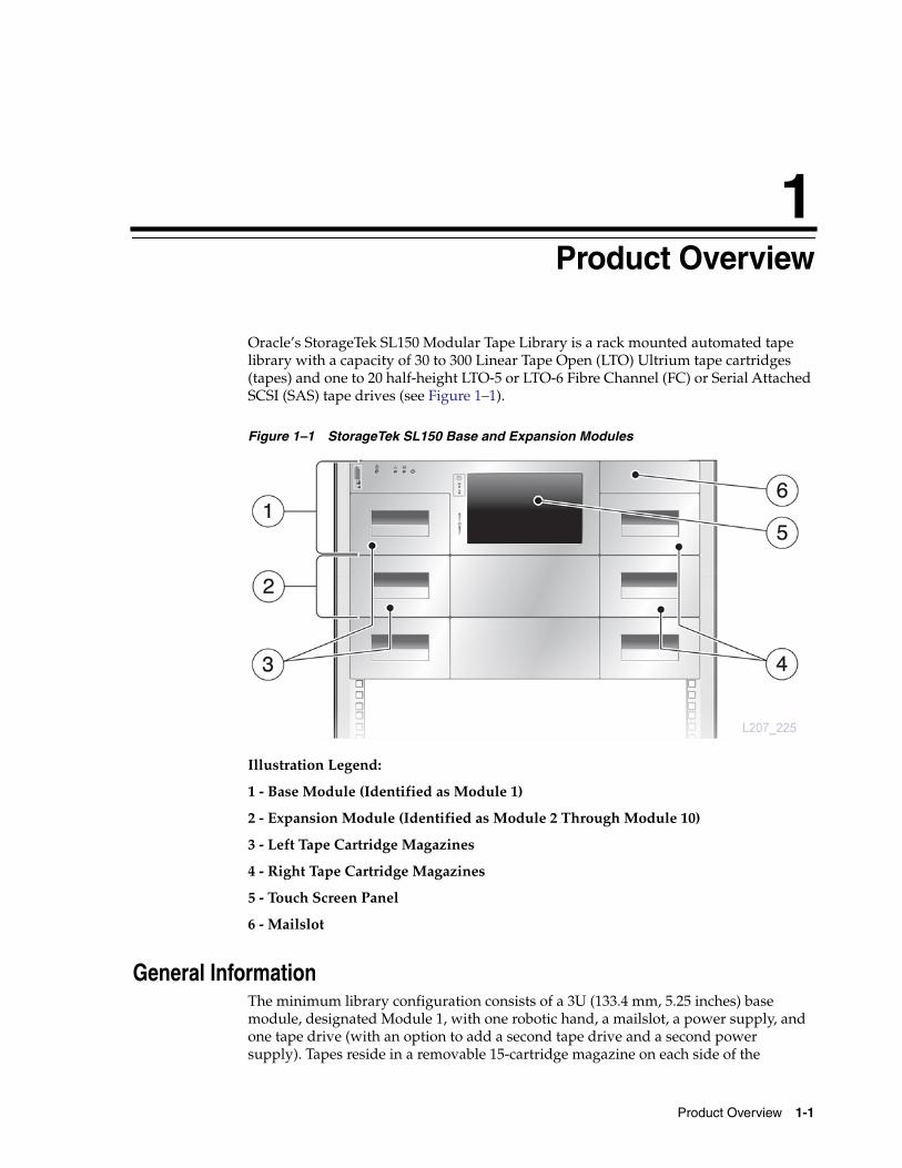
Oracle’s StorageTek SL150 Modular Tape Library is a rack mounted automated tapelibrary with a capacity of 30 to 300 Linear Tape Open (LTO) Ultrium tape cartridges(tapes) and one to 20 half-height LTO-5 or LTO-6 Fibre Channel (FC) or Serial AttachedSCSI (SAS) tape drives (see Figure 1–1).
Figure 1–1 StorageTek SL150 Base and Expansion Modules
Illustration Legend:
1 - Base Module (Identified as Module 1)
2 - Expansion Module (Identified as Module 2 Through Module 10)
3 - Left Tape Cartridge Magazines
4 - Right Tape Cartridge Magazines
5 - Touch Screen Panel
6 - Mailslot
General InformationThe minimum library configuration consists of a 3U (133.4 mm, 5.25 inches) basemodule, designated Module 1, with one robotic hand, a mailslot, a power supply, andone tape drive (with an option to add a second tape drive and a second powersupply). Tapes reside in a removable 15-cartridge magazine on each side of the
General Information
1-2 StorageTek SL150 Modular Tape Library Customer Replaceable Unit Guide
module. Up to three tape slots of the base module left magazine can be designated asreserved slots to store diagnostic or cleaning tapes.
The external interface for library control is provided by a bridged tape drive. The robotcontrol is a SCSI Medium Changer device appearing as LUN 1 on a tape drive. Thebase module is the smallest fully functional library.
The library can be expanded from one to ten modules. A 2U (88.9 mm, 3.5 inches)expansion module provides the library an additional capacity of 30 tapes and up totwo tape drives. Expansion modules are designated Module 2 through Module 10.Modules provide two 15-cartridge magazines, slots for up to two tape drives, and slotsfor up to two power supplies.
A graphical user interface (GUI) provides local or remote role-based access control ofthe SL150 Library.
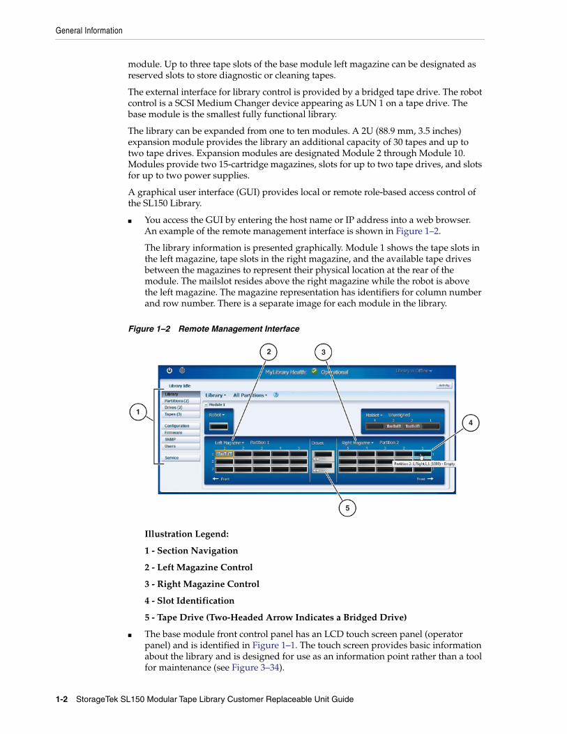
■ You access the GUI by entering the host name or IP address into a web browser.An example of the remote management interface is shown in Figure 1–2.
The library information is presented graphically. Module 1 shows the tape slots inthe left magazine, tape slots in the right magazine, and the available tape drivesbetween the magazines to represent their physical location at the rear of themodule. The mailslot resides above the right magazine while the robot is abovethe left magazine. The magazine representation has identifiers for column numberand row number. There is a separate image for each module in the library.
Figure 1–2 Remote Management Interface
Illustration Legend:
1 - Section Navigation
2 - Left Magazine Control
3 - Right Magazine Control
4 - Slot Identification
5 - Tape Drive (Two-Headed Arrow Indicates a Bridged Drive)
■ The base module front control panel has an LCD touch screen panel (operatorpanel) and is identified in Figure 1–1. The touch screen provides basic informationabout the library and is designed for use as an information point rather than a toolfor maintenance (see Figure 3–34).
Library Status Indicators
Product Overview 1-3
The front control panel touch screen is also used to perform basic initializationsetup with an initialization wizard.
Additional library management functions are performed by the administratorusing the remote management interface.
The SL150 Library supports partitions. Each partition has an assigned bridged tapedrive, and each partition behaves as an independent library. All partitions share theuse of the single robot, reserved slots, and mailslot.
Note: Code versions below 2.0 support two partitions, but codeversions 2.0 and above support up to eight partitions.
Class 1 Laser Product NoticeThe StorageTek SL150 Modular Tape Library contains a class-1 laser as defined by IEC60825-1 Ed. 2 (2007).
Warning: Use of controls or adjustments or performance ofprocedures other than those specified herein may result inhazardous radiation exposure.
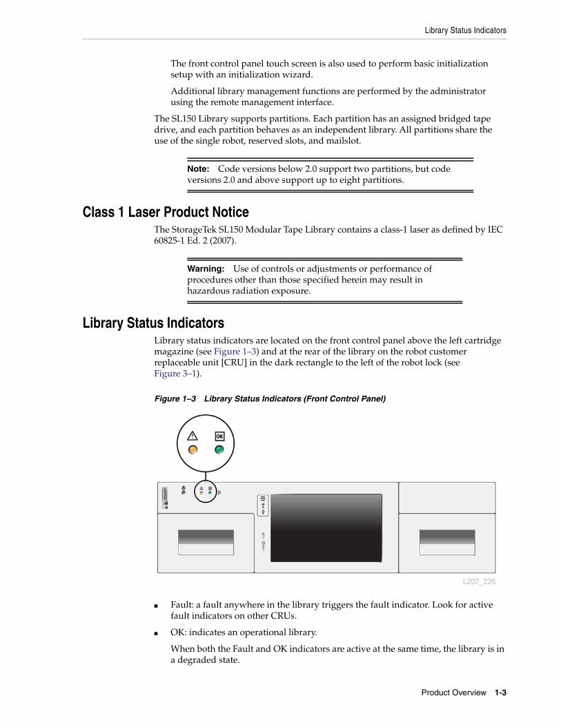
Library Status IndicatorsLibrary status indicators are located on the front control panel above the left cartridgemagazine (see Figure 1–3) and at the rear of the library on the robot customerreplaceable unit [CRU] in the dark rectangle to the left of the robot lock (seeFigure 3–1).
Figure 1–3 Library Status Indicators (Front Control Panel)
■ Fault: a fault anywhere in the library triggers the fault indicator. Look for activefault indicators on other CRUs.
■ OK: indicates an operational library.
When both the Fault and OK indicators are active at the same time, the library is ina degraded state.
Customer Replaceable Units
1-4 StorageTek SL150 Modular Tape Library Customer Replaceable Unit Guide
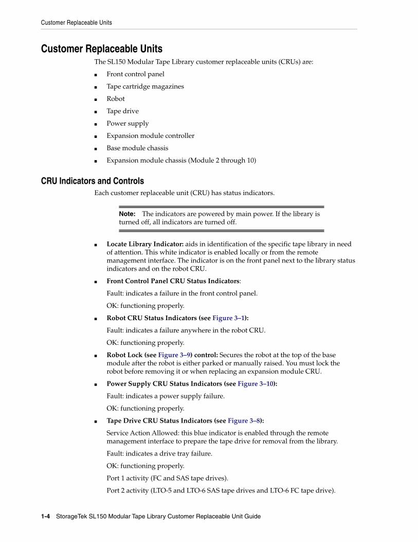
Customer Replaceable UnitsThe SL150 Modular Tape Library customer replaceable units (CRUs) are:
■ Front control panel
■ Tape cartridge magazines
■ Robot
■ Tape drive
■ Power supply
■ Expansion module controller
■ Base module chassis
■ Expansion module chassis (Module 2 through 10)
CRU Indicators and ControlsEach customer replaceable unit (CRU) has status indicators.
Note: The indicators are powered by main power. If the library isturned off, all indicators are turned off.
■ Locate Library Indicator: aids in identification of the specific tape library in needof attention. This white indicator is enabled locally or from the remotemanagement interface. The indicator is on the front panel next to the library statusindicators and on the robot CRU.
■ Front Control Panel CRU Status Indicators:
Fault: indicates a failure in the front control panel.
OK: functioning properly.
■ Robot CRU Status Indicators (see Figure 3–1):
Fault: indicates a failure anywhere in the robot CRU.
OK: functioning properly.
■ Robot Lock (see Figure 3–9) control: Secures the robot at the top of the basemodule after the robot is either parked or manually raised. You must lock therobot before removing it or when replacing an expansion module CRU.
■ Power Supply CRU Status Indicators (see Figure 3–10):
Fault: indicates a power supply failure.
OK: functioning properly.
■ Tape Drive CRU Status Indicators (see Figure 3–8):
Service Action Allowed: this blue indicator is enabled through the remotemanagement interface to prepare the tape drive for removal from the library.
Fault: indicates a drive tray failure.
OK: functioning properly.
Port 1 activity (FC and SAS tape drives).
Port 2 activity (LTO-5 and LTO-6 SAS tape drives and LTO-6 FC tape drive).
Customer Replaceable Units
Product Overview 1-5
Encryption status: on when a key is present during drive operation.
Encryption reset: a push button switch to reset the tape drive to a default IPaddress.
■ Module Controller CRU Status Indicators (see Figure 3–18):
Fault: a fault anywhere in the module controller (KLE card) triggers the faultindicator and turns off the OK indicator for that specific controller (a library canhave up to nine module controllers).
OK: functioning properly.

Customer Replaceable Units
1-6 StorageTek SL150 Modular Tape Library Customer Replaceable Unit Guide
2
Preparations 2-1
2Preparations
This chapter introduces general topics for your consideration before performing aCRU removal or replacement procedure.
Electrostatic DischargeBe aware of the precautions needed when handling parts. A discharge of staticelectricity from a finger or other conductor might damage static-sensitive devices. Thistype of damage may reduce the life expectancy of the product.
Electrostatic Discharge Prevention■ Avoid hand contact by transporting and storing products in static-safe containers.
■ Keep electrostatic-sensitive parts in their containers until they arrive at static-freework areas.
■ Place parts on a grounded surface before removing them from the container.
■ Avoid touching pins, leads, or circuitry.
■ Use proper grounding practices when touching a static-sensitive component orassembly.
Grounding Methods to Prevent Electrostatic DischargeUse one or more of the following methods when handling or installingelectrostatic-sensitive parts:
■ Use a wrist strap connected by a ground cord to a grounded chassis.
■ Use conductive field service tools.
■ Use a portable field service kit with a folding static-dissipating work mat.
Note: If you do not have any of the suggested equipment forproper grounding, arrange for an authorized reseller to install thepart.
SL150 Remote InterfaceThe process of removing and replacing customer replaceable units (CRUs) relies onfunctions and commands in the SL150 remote interface (GUI). It is assumed that youare familiar with the library section of that interface.
SL150 Remote Interface
2-2 StorageTek SL150 Modular Tape Library Customer Replaceable Unit Guide
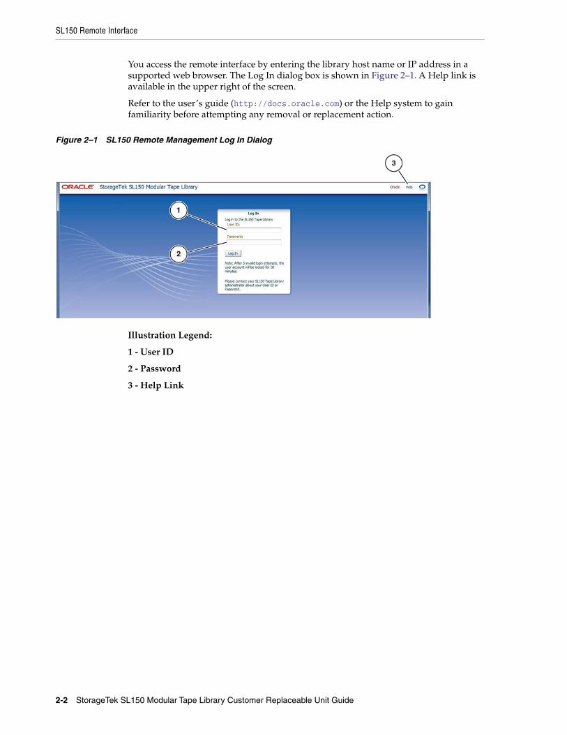
You access the remote interface by entering the library host name or IP address in asupported web browser. The Log In dialog box is shown in Figure 2–1. A Help link isavailable in the upper right of the screen.
Refer to the user’s guide (http://docs.oracle.com) or the Help system to gainfamiliarity before attempting any removal or replacement action.
Figure 2–1 SL150 Remote Management Log In Dialog
Illustration Legend:
1 - User ID
2 - Password
3 - Help Link
3
Removal and Replacement 3-1
3Removal and Replacement
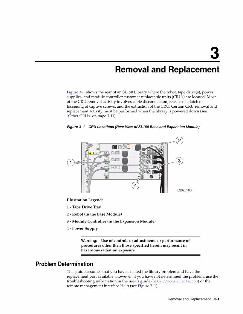
Figure 3–1 shows the rear of an SL150 Library where the robot, tape drive(s), powersupplies, and module controller customer replaceable units (CRUs) are located. Mostof the CRU removal activity involves cable disconnection, release of a latch orloosening of captive screws, and the extraction of the CRU. Certain CRU removal andreplacement activity must be performed when the library is powered down (see"Other CRUs" on page 3-11).
Figure 3–1 CRU Locations (Rear View of SL150 Base and Expansion Module)
Illustration Legend:
1 - Tape Drive Tray
2 - Robot (in the Base Module)
3 - Module Controller (in the Expansion Module)
4 - Power Supply
Warning: Use of controls or adjustments or performance ofprocedures other than those specified herein may result inhazardous radiation exposure.
Problem DeterminationThis guide assumes that you have isolated the library problem and have thereplacement part available. However, if you have not determined the problem; use thetroubleshooting information in the user’s guide (http://docs.oracle.com) or theremote management interface Help (see Figure 2–1).
Common Procedures
3-2 StorageTek SL150 Modular Tape Library Customer Replaceable Unit Guide
Common ProceduresThis section has some common procedures used in various CRU removal procedures.
■ Set the library offline to make sure the host tape management system is notifiedthat something is manually changed in its database and to place the library inmaintenance mode.
■ Set the library online to remove the library from maintenance mode and return thelibrary to host application control.
■ Enable the Locate light to aid in finding the library in the data center.
To Set the Library Offline1. Quiesce the host application to prevent disruption of active storage operations.
2. Log in to the SL150 remote interface using your browser (see Figure 2–1).
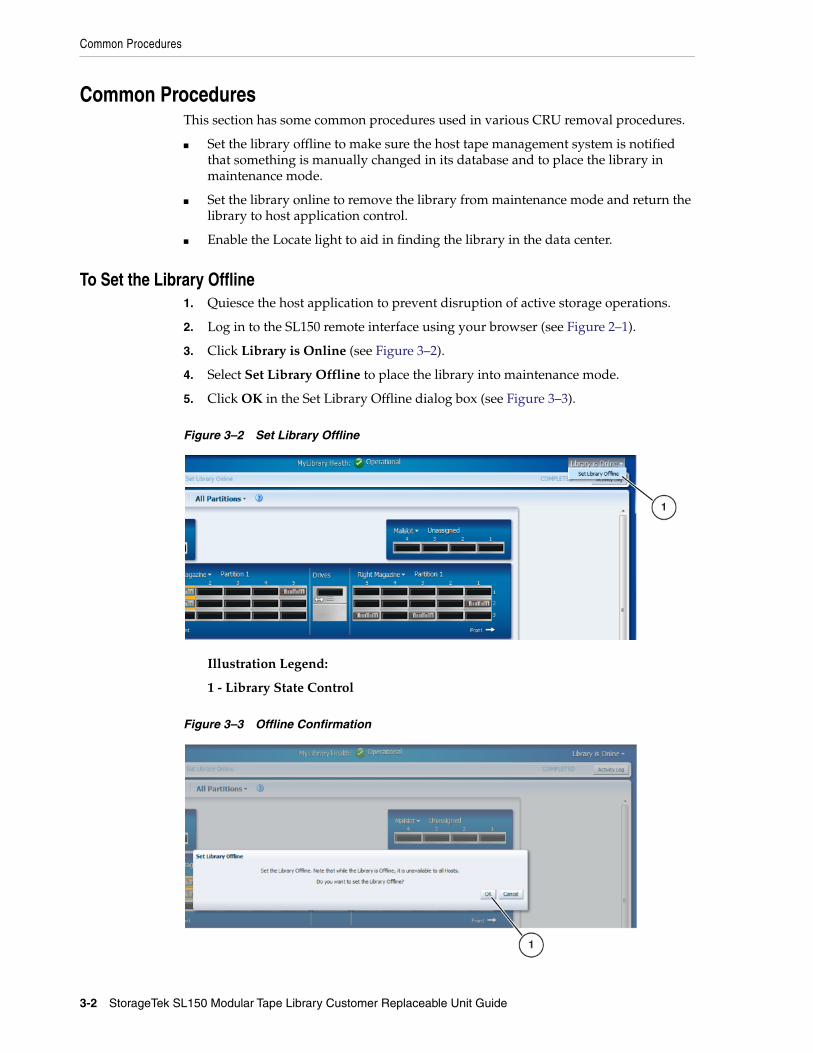
3. Click Library is Online (see Figure 3–2).
4. Select Set Library Offline to place the library into maintenance mode.
5. Click OK in the Set Library Offline dialog box (see Figure 3–3).
Figure 3–2 Set Library Offline
Illustration Legend:
1 - Library State Control
Figure 3–3 Offline Confirmation
Common Procedures
Removal and Replacement 3-3
Illustration Legend:
1 - Confirmation Dialog Box (OK Button)
To Set the Library Online1. Log in to the SL150 remote interface using your browser (see Figure 2–1).
2. Click Library is Offline.
3. Select Set Library Online (takes the library out of maintenance mode).
4. Click OK in the dialog box.
The library state changes to online.
To Enable the Locate Light1. Log in to the SL150 remote interface using your browser (see Figure 2–1).
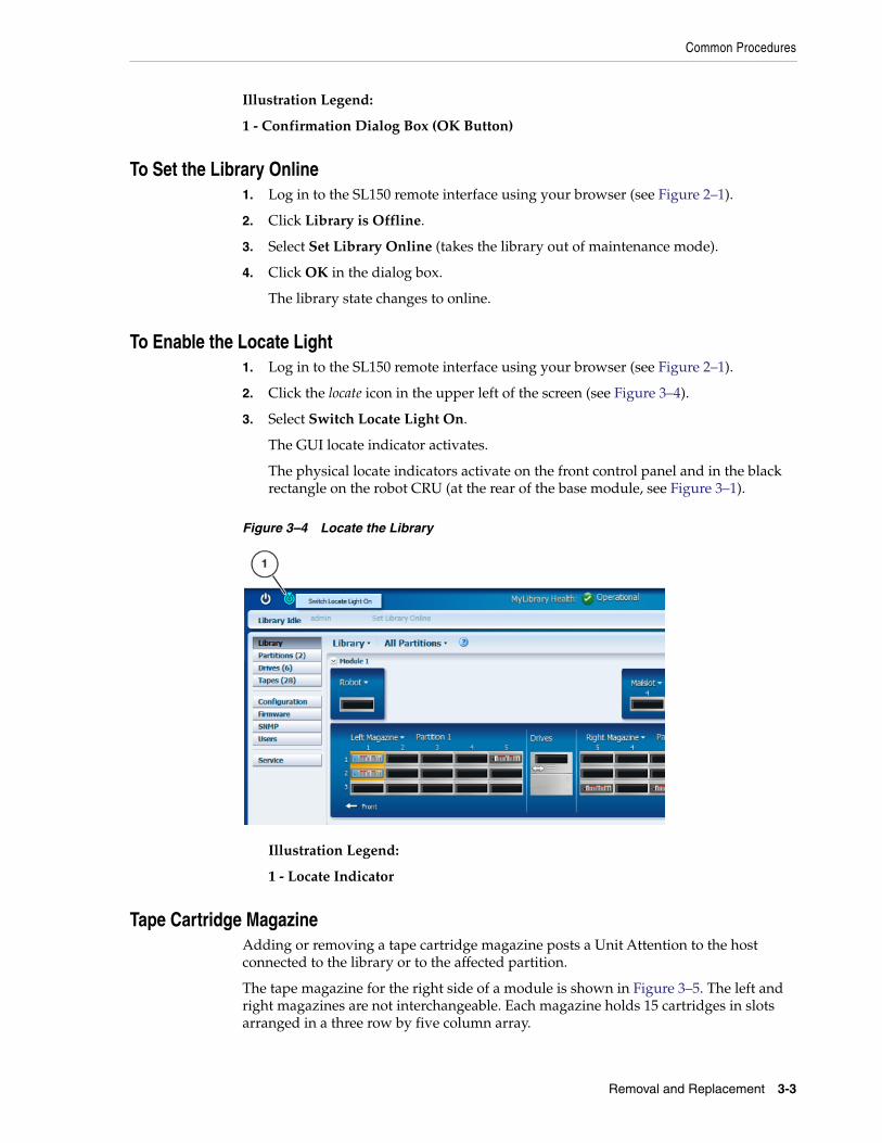
2. Click the locate icon in the upper left of the screen (see Figure 3–4).
3. Select Switch Locate Light On.
The GUI locate indicator activates.
The physical locate indicators activate on the front control panel and in the blackrectangle on the robot CRU (at the rear of the base module, see Figure 3–1).
Figure 3–4 Locate the Library
Illustration Legend:
1 - Locate Indicator
Tape Cartridge MagazineAdding or removing a tape cartridge magazine posts a Unit Attention to the hostconnected to the library or to the affected partition.
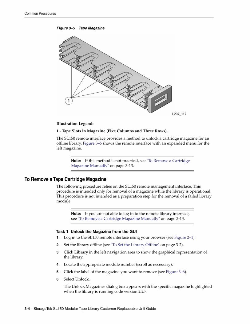
The tape magazine for the right side of a module is shown in Figure 3–5. The left andright magazines are not interchangeable. Each magazine holds 15 cartridges in slotsarranged in a three row by five column array.
Common Procedures
3-4 StorageTek SL150 Modular Tape Library Customer Replaceable Unit Guide
Figure 3–5 Tape Magazine
Illustration Legend:
1 - Tape Slots in Magazine (Five Columns and Three Rows).
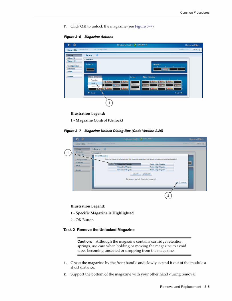
The SL150 remote interface provides a method to unlock a cartridge magazine for anoffline library. Figure 3–6 shows the remote interface with an expanded menu for theleft magazine.
Note: If this method is not practical, see "To Remove a CartridgeMagazine Manually" on page 3-13.
To Remove a Tape Cartridge MagazineThe following procedure relies on the SL150 remote management interface. Thisprocedure is intended only for removal of a magazine while the library is operational.This procedure is not intended as a preparation step for the removal of a failed librarymodule.
Note: If you are not able to log in to the remote library interface,see "To Remove a Cartridge Magazine Manually" on page 3-13.
Task 1 Unlock the Magazine from the GUI1. Log in to the SL150 remote interface using your browser (see Figure 2–1).
2. Set the library offline (see "To Set the Library Offline" on page 3-2).
3. Click Library in the left navigation area to show the graphical representation ofthe library.
4. Locate the appropriate module number (scroll as necessary).
5. Click the label of the magazine you want to remove (see Figure 3–6).
6. Select Unlock.
The Unlock Magazines dialog box appears with the specific magazine highlightedwhen the library is running code version 2.25.
Common Procedures
Removal and Replacement 3-5
7. Click OK to unlock the magazine (see Figure 3–7).
Figure 3–6 Magazine Actions
Illustration Legend:
1 - Magazine Control (Unlock)
Figure 3–7 Magazine Unlock Dialog Box (Code Version 2.25)
Illustration Legend:
1 - Specific Magazine is Highlighted
2 - OK Button
Task 2 Remove the Unlocked Magazine
Caution: Although the magazine contains cartridge retentionsprings, use care when holding or moving the magazine to avoidtapes becoming unseated or dropping from the magazine.
1. Grasp the magazine by the front handle and slowly extend it out of the module ashort distance.
2. Support the bottom of the magazine with your other hand during removal.
Hot Swappable CRUs
3-6 StorageTek SL150 Modular Tape Library Customer Replaceable Unit Guide
3. Pull the magazine free of the module and set it aside.
To Replace a Tape Cartridge Magazine
Caution: Although the magazine contains cartridge retentionsprings, use care when holding or moving the magazine to avoidunseating or dropping cartridges.
1. Orient the magazine with the cartridge slots facing toward the center of themodule.
2. Lift the magazine and point the back of it toward the module slot.
3. Engage the magazine with the track in the magazine bay of the module.
4. Verify all tapes are properly seated in the magazine slots.
5. Push the magazine fully into the library module.
6. From the Library list, select Lock and Audit.
Note: Code levels before 2.25 do not have the Lock and Auditcommand.
7. Select the Set the Library back online after applying this action check box in theLock and Audit dialog box.
8. Click OK.
Hot Swappable CRUsThis section provides removal and replacement instructions for the tape drive tray andpower supply CRUs that you can replace while power is applied to the library. Youtemporarily remove the power supply or drive tray assembly and then insert thecorresponding CRU in the open slot.
Warning: Do not operate the library with open tape drive orpower supply slots.
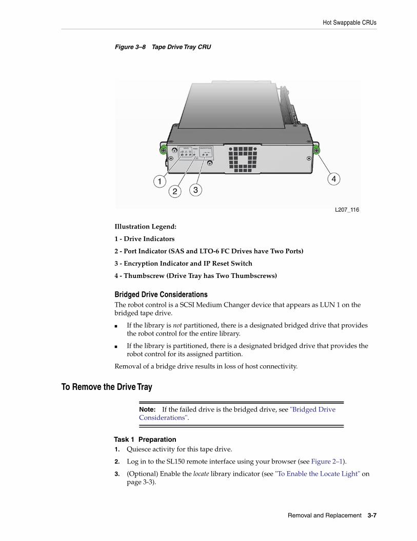
Drive Tray AssemblyThe drive tray assembly (drive tray) is located in the center, rear of the module (seeFigure 3–1). The drive tray has a series of indicators on the back panel (see Figure 3–8),an exposed circuit card near the right side thumbscrew, a tape drive, and a chassis(also referred to as a sled).
Hot Swappable CRUs
Removal and Replacement 3-7
Figure 3–8 Tape Drive Tray CRU
Illustration Legend:
1 - Drive Indicators
2 - Port Indicator (SAS and LTO-6 FC Drives have Two Ports)
3 - Encryption Indicator and IP Reset Switch
4 - Thumbscrew (Drive Tray has Two Thumbscrews)
Bridged Drive ConsiderationsThe robot control is a SCSI Medium Changer device that appears as LUN 1 on thebridged tape drive.
■ If the library is not partitioned, there is a designated bridged drive that providesthe robot control for the entire library.
■ If the library is partitioned, there is a designated bridged drive that provides therobot control for its assigned partition.
Removal of a bridge drive results in loss of host connectivity.
To Remove the Drive Tray
Note: If the failed drive is the bridged drive, see "Bridged DriveConsiderations".
Task 1 Preparation1. Quiesce activity for this tape drive.
2. Log in to the SL150 remote interface using your browser (see Figure 2–1).
3. (Optional) Enable the locate library indicator (see "To Enable the Locate Light" onpage 3-3).
Hot Swappable CRUs
3-8 StorageTek SL150 Modular Tape Library Customer Replaceable Unit Guide
Task 2 Prepare the Tape Drive Tray for Removal1. Click Library in the left navigation area to show the graphical representation of
the library. Click the button beside the module identifier if the module map iscollapsed.
2. Move the cursor to the drive you want to replace.
A drive has a location in the module (top or bottom) and a SCSI address.
3. Right click the drive icon and select Remove Drive.
4. Click OK in the confirmation dialog box.
The physical indicator at the rear of the drive tray lights to indicate the drive isready for removal.
Task 3 Remove the Tape Drive Tray1. Access the back of the library (open the rear door of the rack, if applicable).
2. Locate the drive tray with the blue indicator (drive is ready for removal).
3. Verify that the interface cables are labeled. Attach a label if necessary.
4. Disconnect the cables from the jacks on the drive tray (see Figure 3–1).
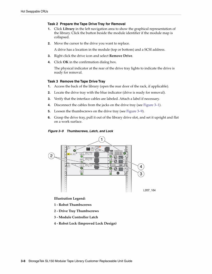
5. Loosen the thumbscrews on the drive tray (see Figure 3–9).
6. Grasp the drive tray, pull it out of the library drive slot, and set it upright and flaton a work surface.
Figure 3–9 Thumbscrews, Latch, and Lock
Illustration Legend:
1 - Robot Thumbscrews
2 - Drive Tray Thumbscrews
3 - Module Controller Latch
4 - Robot Lock (Improved Lock Design)

Hot Swappable CRUs
Removal and Replacement 3-9
To Replace the Drive Tray
Task 1 Preparation
Caution: Equipment damage. Do not touch the circuit card orstatic sensitive components.
1. Follow accepted practices to prevent damage from ESD.
2. Remove the replacement drive tray from the shipping carton. Save the packagingmaterials for the return of the failed CRU.
Note: Handle the drive tray by the rear corners (close to thethumbscrews) and the bottom of the tray. Avoid contact with thetop cover of the actual tape drive.
Task 2 Replace the Drive Tray1. Grasp the rear corners of the drive tray.
2. Guide the front of the drive tray into the module drive slot.
3. Push the drive tray completely into the drive slot.
4. Verify that the indicators are active on the rear of the drive tray.
5. Tighten the thumbscrews firmly on each side of the drive tray to make sure thereis no tray movement in any direction.
6. Push the Locate indicator on the robot CRU to reset the light, if applicable.
7. Connect the interface cable(s) and Ethernet cable (if applicable) to the proper jackon the left side of the drive tray.
Task 3 Confirmation1. Confirm that the library recognizes and accounts for the drive (Drives area of the
SL150 remote interface).
It can take some time for the indicators to show the drive is operational.
2. Make sure the drive port is enabled (view the Drive Properties and change drivesettings if appropriate).
3. Identify the tape drive firmware version and, if necessary, upgrade it.
Refer to the StorageTek SL150 Modular Tape Library User’s Guide or the Help systemfor instructions if your library is running code version 2.0 or higher.
If your library code is lower than 2.0, follow the instructions in the drive codeReadMe file.
4. Log out of the SL150 remote interface.
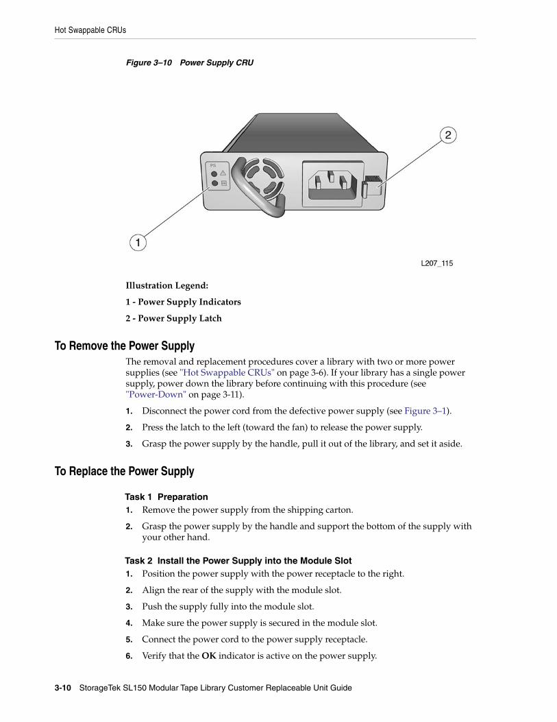
Power SupplyThe power supply (Figure 3–10) has indicators in the upper left corner and a releaselatch to the right of the power receptacle.
Module 1 requires one power supply (see Figure 3–1). Expansion modules with aninstalled drive require a power supply.
Hot Swappable CRUs
3-10 StorageTek SL150 Modular Tape Library Customer Replaceable Unit Guide
Figure 3–10 Power Supply CRU
Illustration Legend:
1 - Power Supply Indicators
2 - Power Supply Latch
To Remove the Power SupplyThe removal and replacement procedures cover a library with two or more powersupplies (see "Hot Swappable CRUs" on page 3-6). If your library has a single powersupply, power down the library before continuing with this procedure (see"Power-Down" on page 3-11).
1. Disconnect the power cord from the defective power supply (see Figure 3–1).
2. Press the latch to the left (toward the fan) to release the power supply.
3. Grasp the power supply by the handle, pull it out of the library, and set it aside.
To Replace the Power Supply
Task 1 Preparation1. Remove the power supply from the shipping carton.
2. Grasp the power supply by the handle and support the bottom of the supply withyour other hand.
Task 2 Install the Power Supply into the Module Slot1. Position the power supply with the power receptacle to the right.
2. Align the rear of the supply with the module slot.
3. Push the supply fully into the module slot.
4. Make sure the power supply is secured in the module slot.
5. Connect the power cord to the power supply receptacle.
6. Verify that the OK indicator is active on the power supply.
Note: Continue with "Power System Behavior" on page 3-35 if thepower supply indicator is not active.
Other CRUs
Removal and Replacement 3-11
Other CRUsYou must remove power from the library when working on the following CRUs:
■ Robot
■ Module Controller
■ Front Control Panel
■ Base and Expansion Module Chassis
Caution: The robot, front control panel, and base module chassis arecritical to maintaining the product serial number and customersettings. When a replacement is needed for any of these CRUs, youmay only replace one CRU during a single power down cycle.
In addition, you must remove tape cartridge magazines to replace the Front ControlPanel, Base Module, and Expansion Module CRUs.
Preparation ProceduresThis section provides procedures to remove library power and manually remove acartridge magazine to gain access to the screws securing the module to the rack.
Power-DownThere are two methods of removing power from the library: controlled and forced.
■ Perform the controlled power down using either the Front Control Panel powerbutton or the SL150 remote interface power icon.
■ Perform the forced shutdown method at the library or rack power source.
Note: Use the forced power-down method only when thecontrolled method does not work (see "To Perform a ForcedPower-Down" on page 3-13).
To Perform a Controlled Power-Down from the GUI1. Quiesce the host application to prevent disruption of active storage operations.
2. Log in to the SL150 remote interface using your browser (see Figure 2–1).
3. Click the power icon in the upper left of the screen (see Figure 3–11).
4. Select Power Down Library.
5. Select Prepare the Robot for removal before the library powers down, ifapplicable (see Figure 3–12).
6. Click OK.
7. Follow the on-screen prompts (for example, instructions to lock the robot).
Other CRUs
3-12 StorageTek SL150 Modular Tape Library Customer Replaceable Unit Guide
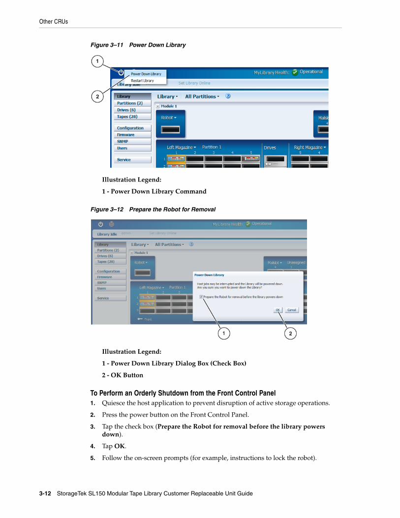
Figure 3–11 Power Down Library
Illustration Legend:
1 - Power Down Library Command
Figure 3–12 Prepare the Robot for Removal
Illustration Legend:
1 - Power Down Library Dialog Box (Check Box)
2 - OK Button
To Perform an Orderly Shutdown from the Front Control Panel1. Quiesce the host application to prevent disruption of active storage operations.
2. Press the power button on the Front Control Panel.
3. Tap the check box (Prepare the Robot for removal before the library powersdown).
4. Tap OK.
5. Follow the on-screen prompts (for example, instructions to lock the robot).
Other CRUs
Removal and Replacement 3-13
To Perform a Forced Power-Down1. Quiesce the host application to prevent disruption of active storage operations.
2. (Optional) Enable the locate library indicator (see "To Enable the Locate Light" onpage 3-3).
3. Find the rack containing the library you want to power down.
4. Remove power from the library using one of the following methods:
a. Use the forced (hard) shutdown method. Press the front panel power buttonand hold it until the library shuts down (approximately 10 seconds).
b. (Optional) Use the physical method, if the hard shutdown does not work.Remove power from all power supplies (disconnect the power cord from allpower supplies or set the PDU or power strip switch to the off position).
To Remove a Cartridge Magazine Manually
Caution: Manual removal of a tape cartridge magazine candamage the robotic mechanism. This procedure supports removaland replacement for some CRUs listed in "Other CRUs" onpage 3-11. Power down the library before beginning this procedure.
Task 1 Release the Magazine Latch1. Power down the library (see "Power-Down" on page 3-11).
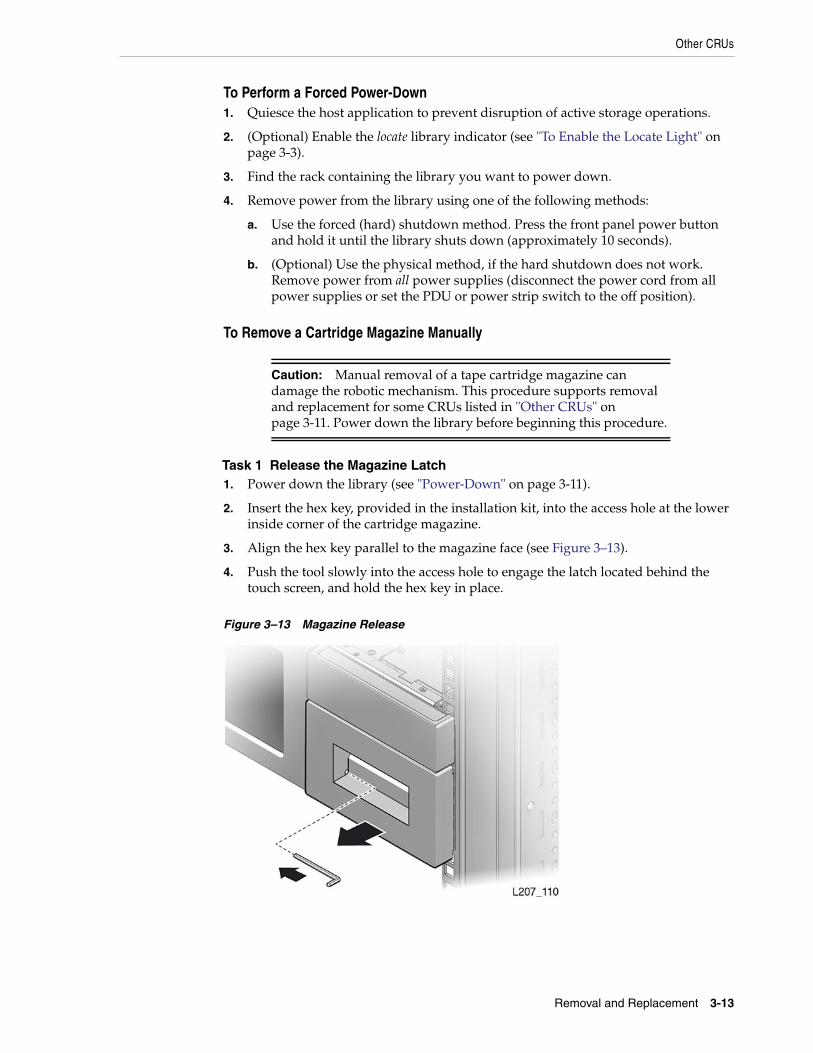
2. Insert the hex key, provided in the installation kit, into the access hole at the lowerinside corner of the cartridge magazine.
3. Align the hex key parallel to the magazine face (see Figure 3–13).
4. Push the tool slowly into the access hole to engage the latch located behind thetouch screen, and hold the hex key in place.
Figure 3–13 Magazine Release
Other CRUs
3-14 StorageTek SL150 Modular Tape Library Customer Replaceable Unit Guide
Task 2 Remove the Magazine
Caution: Although the magazine contains cartridge retentionsprings, use care while holding or moving the magazine to avoiddropping cartridges.
1. Grasp the tape cartridge magazine opening with your other hand and pull themagazine a short distance out of the library.
2. Remove the hex key and store it for future use.
3. Support the bottom of the magazine with your other hand during removal.
4. Pull the magazine free of the library module and set it aside.
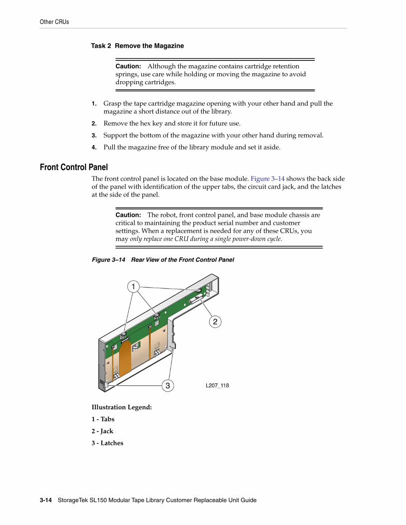
Front Control PanelThe front control panel is located on the base module. Figure 3–14 shows the back sideof the panel with identification of the upper tabs, the circuit card jack, and the latchesat the side of the panel.
Caution: The robot, front control panel, and base module chassis arecritical to maintaining the product serial number and customersettings. When a replacement is needed for any of these CRUs, youmay only replace one CRU during a single power-down cycle.
Figure 3–14 Rear View of the Front Control Panel
Illustration Legend:
1 - Tabs
2 - Jack
3 - Latches
Other CRUs
Removal and Replacement 3-15
To Remove the Front Control Panel1. Power down the library (see "To Perform a Controlled Power-Down from the GUI"
on page 3-11).
2. Remove both cartridge magazines from the base module (see "To Remove aCartridge Magazine Manually" on page 3-13).
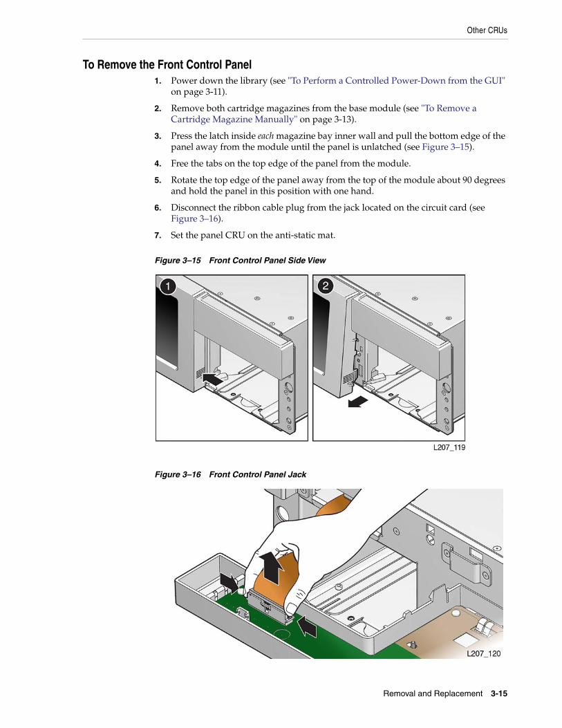
3. Press the latch inside each magazine bay inner wall and pull the bottom edge of thepanel away from the module until the panel is unlatched (see Figure 3–15).
4. Free the tabs on the top edge of the panel from the module.
5. Rotate the top edge of the panel away from the top of the module about 90 degreesand hold the panel in this position with one hand.
6. Disconnect the ribbon cable plug from the jack located on the circuit card (seeFigure 3–16).
7. Set the panel CRU on the anti-static mat.
Figure 3–15 Front Control Panel Side View
Figure 3–16 Front Control Panel Jack
Other CRUs
3-16 StorageTek SL150 Modular Tape Library Customer Replaceable Unit Guide
To Replace the Front Control Panel
Caution: ESD damage. Do not touch any exposed electroniccomponents, cables, or contacts.
1. Remove the replacement front control panel from its packaging.
2. Grasp the panel by the plastic housing and raise it to the base module.
3. Attach the cable to the circuit card jack at the back of the panel. Make sure theconnector is flush with the jack.
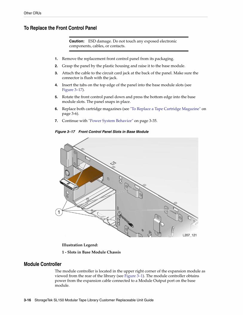
4. Insert the tabs on the top edge of the panel into the base module slots (seeFigure 3–17).
5. Rotate the front control panel down and press the bottom edge into the basemodule slots. The panel snaps in place.
6. Replace both cartridge magazines (see "To Replace a Tape Cartridge Magazine" onpage 3-6).
7. Continue with "Power System Behavior" on page 3-35.
Figure 3–17 Front Control Panel Slots in Base Module
Illustration Legend:
1 - Slots in Base Module Chassis
Module ControllerThe module controller is located in the upper right corner of the expansion module asviewed from the rear of the library (see Figure 3–1). The module controller obtainspower from the expansion cable connected to a Module Output port on the basemodule.
Other CRUs
Removal and Replacement 3-17
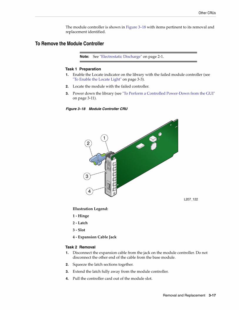
The module controller is shown in Figure 3–18 with items pertinent to its removal andreplacement identified.
To Remove the Module Controller
Note: See "Electrostatic Discharge" on page 2-1.
Task 1 Preparation1. Enable the Locate indicator on the library with the failed module controller (see
"To Enable the Locate Light" on page 3-3).
2. Locate the module with the failed controller.
3. Power down the library (see "To Perform a Controlled Power-Down from the GUI"on page 3-11).
Figure 3–18 Module Controller CRU
Illustration Legend:
1 - Hinge
2 - Latch
3 - Slot
4 - Expansion Cable Jack
Task 2 Removal1. Disconnect the expansion cable from the jack on the module controller. Do not
disconnect the other end of the cable from the base module.
2. Squeeze the latch sections together.
3. Extend the latch fully away from the module controller.
4. Pull the controller card out of the module slot.
Other CRUs
3-18 StorageTek SL150 Modular Tape Library Customer Replaceable Unit Guide
5. Set the module controller on the anti-static work surface.
To Replace the Module Controller
Caution: ESD damage. Do not touch any electronic componentsor electrical contacts.
1. Remove the replacement module controller from the ESD packaging.
2. Grasp the module controller without touching components or electrical contacts.
3. Open the retaining latch.
4. Insert the module controller, component side up, in the module slot.
5. Seat the latch in the slot to secure the module controller.
6. Connect the expansion cable to the jack on the module controller.
The other end of the cable is already connected to a Module Output port on therobot CRU.
7. Insert the failed module controller into the ESD packaging.
8. Continue with "Power System Behavior" on page 3-35.
Robot ModuleThe robot module is located at the top of the base module (see Figure 3–9). The robotmust be parked in the base module, the robot lock engaged, and the thumbscrewsloosened before attempting to remove the robot module.
Both the Front Control Panel and the SL150 remote management interface provide theoption to prepare the robot for removal during the power down process.
Caution: The robot, front control panel, and base module chassis arecritical to maintaining the product serial number and customersettings. When a replacement is needed for any of these CRUs, youmay replace only one CRU during a single power-down cycle.
To Remove the Robot
Caution: It is critical for the robot to be parked and latched beforeattempting to remove the robot CRU.
Task 1 Park and Lock the Robot1. Power down the library (see "To Perform a Controlled Power-Down from the GUI"
on page 3-11) with the “to prepare the robot for removal” option enabled.
If the robot cannot be parked by using the power-down procedure, perform "ToManually Retract the Robot" on page 3-20.
2. Remove the top drive tray or drive filler from the base module.
3. Look through the drive slot and locate the position of the robot.
4. Verify the robot is fully seated against the ceiling of the library.
Other CRUs
Removal and Replacement 3-19
Repeat the parking procedure if necessary to make sure the robot is secured in theproper position.
5. Set the robot lock to the locked position.
If the robot lock is the type with a knob, grasp the knob and turn itcounter-clockwise until the point is past the red, locked padlock icon.
If the robot lock is the type with a screw, loosen the thumbscrew, remove themechanism, rotate the mechanism 180 degrees, insert the mechanism, and tightenthe thumbscrew.
Note: Make sure the locked padlock icon is indicated.
6. Replace the top drive or drive filler in the base module.
Task 2 Robot Removal
Note: The robot CRU weighs approximately 5 kg (11 pounds).
1. Make sure to identify each Ethernet port on the robot and its attached cable (labelthe cable if necessary).
Note: The Ethernet ports might be connected to differentnetworks.
2. Disconnect all cables, Ethernet cable and expansion cable, attached to the robotCRU.
Note: Set the expansion cable(s) aside if the expansion moduleshave been removed in preparation for base module replacement.
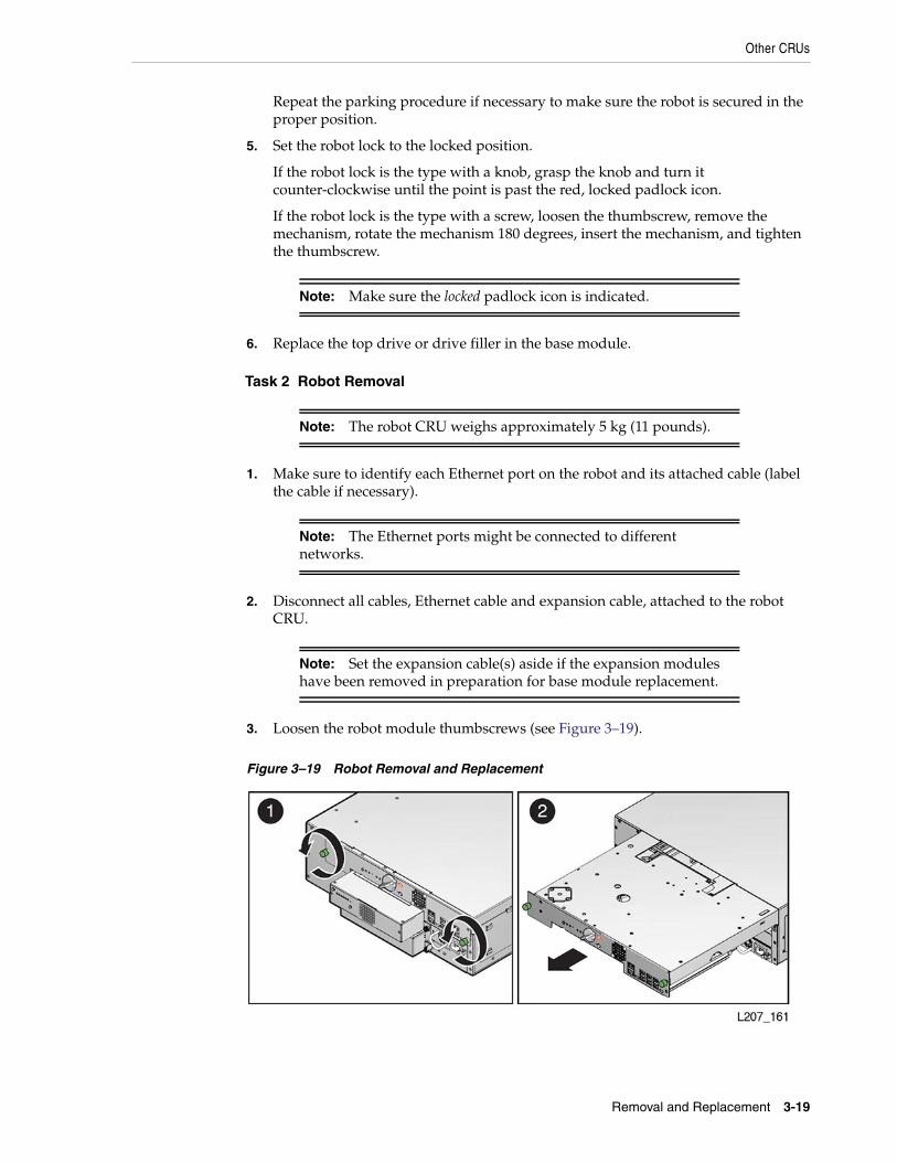
3. Loosen the robot module thumbscrews (see Figure 3–19).
Figure 3–19 Robot Removal and Replacement
Other CRUs
3-20 StorageTek SL150 Modular Tape Library Customer Replaceable Unit Guide
4. Grasp the robot module thumbscrews and pull the robot approximately 254 mm(10 inches) out of the base module.
5. Reposition your hands near the center of the extended robot.
6. Pull the robot completely out of the base module, and set it on the anti-static worksurface.
7. Continue with "To Replace the Robot" on page 3-22.
To Manually Retract the Robot
Note: Perform this procedure if you could not park the robot byusing the power-down procedure.
1. Remove the top drive tray from the base module (see "Drive Tray Assembly" onpage 3-6).
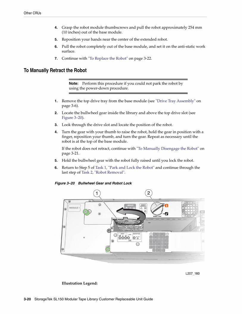
2. Locate the bullwheel gear inside the library and above the top drive slot (seeFigure 3–20).
3. Look through the drive slot and locate the position of the robot.
4. Turn the gear with your thumb to raise the robot, hold the gear in position with afinger, reposition your thumb, and turn the gear. Repeat as necessary until therobot is at the top of the base module.
If the robot does not retract, continue with "To Manually Disengage the Robot" onpage 3-21.
5. Hold the bullwheel gear with the robot fully raised until you lock the robot.
6. Return to Step 5 of Task 1, "Park and Lock the Robot" and continue through thelast step of Task 2, "Robot Removal".
Figure 3–20 Bullwheel Gear and Robot Lock
Illustration Legend:
Other CRUs
Removal and Replacement 3-21
1 - Bullwheel Gear
2 - Robot Lock (Improved Design)
To Manually Disengage the Robot
Caution: Perform this procedure only if either the library powerdown (Step 1 of "Park and Lock the Robot") or "To ManuallyRetract the Robot" does not work. This procedure damages the robotassembly.
Task 1 Cut Cables1. Make sure the library is powered down.
2. Remove all tape drives from the base module.
3. Cut the accordion cable (folded ribbon cable).
4. Reach into the library and cut both rear suspension cables.
5. Cut the front suspension cables.
The Z platform should settle to the floor of the bottom module.
Task 2 Remove the Robot CRU1. Loosen the robot module thumbscrews.
2. Grasp the robot module thumbscrews and pull the robot approximately 254 mm(10 inches) out of the base module.
3. Reposition your hands along the sides of the extended robot and close to the basemodule.
4. Pull the robot completely out of the base module, and set it aside.
Task 3 Remove the Z Platform1. Remove the cartridge magazines from the base module.
2. Remove cartridge magazines from expansion modules until you locate the Zplatform.
Note: You can also perform this procedure at the rear of the libraryby removing the tape drives or drive fillers from the modules, andreaching through the drive openings.
3. Grasp the platform by reaching through either the magazine or tape driveopenings.
4. Raise the platform by hand to the top of the base module.
5. Push the platform through the robot CRU opening at the rear of the base modulefar enough so that it does not slip back inside the library.
6. Go to the back of the library, grasp the robot CRU, and remove it from the library.
Task 4 Finishing Touches1. Inspect the library floor and remove any debris resulting from the broken robot.
Other CRUs
3-22 StorageTek SL150 Modular Tape Library Customer Replaceable Unit Guide
2. Replace all cartridge magazines and tape drives removed during this procedure.
3. Continue with "To Replace the Robot".
To Replace the Robot
Task 1 Preparation1. Remove the replacement robot from its shipping carton, and set it on the anti-static
mat. Save the packaging materials for the return of the failed CRU.
Task 2 Replacement1. Grasp the robot near the center with the thumbscrews facing you.
2. Insert the robot into the base module (see Figure 3–19).
3. Push the robot fully into the module.
4. Tighten the thumbscrews on each side of the robot CRU.
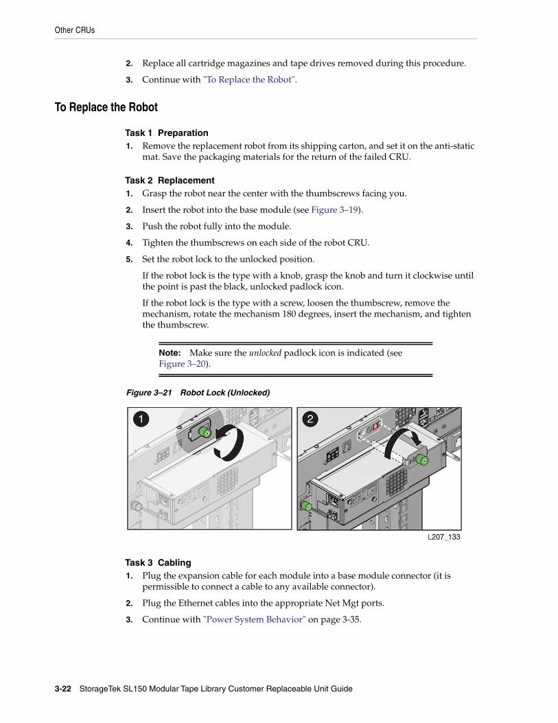
5. Set the robot lock to the unlocked position.
If the robot lock is the type with a knob, grasp the knob and turn it clockwise untilthe point is past the black, unlocked padlock icon.
If the robot lock is the type with a screw, loosen the thumbscrew, remove themechanism, rotate the mechanism 180 degrees, insert the mechanism, and tightenthe thumbscrew.
Note: Make sure the unlocked padlock icon is indicated (seeFigure 3–20).
Figure 3–21 Robot Lock (Unlocked)
Task 3 Cabling1. Plug the expansion cable for each module into a base module connector (it is
permissible to connect a cable to any available connector).
2. Plug the Ethernet cables into the appropriate Net Mgt ports.
3. Continue with "Power System Behavior" on page 3-35.
Other CRUs
Removal and Replacement 3-23
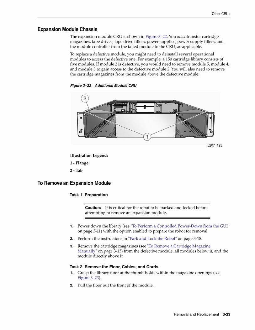
Expansion Module ChassisThe expansion module CRU is shown in Figure 3–22. You must transfer cartridgemagazines, tape drives, tape drive fillers, power supplies, power supply fillers, andthe module controller from the failed module to the CRU, as applicable.
To replace a defective module, you might need to deinstall several operationalmodules to access the defective one. For example, a 150 cartridge library consists offive modules. If module 2 is defective, you would need to remove module 5, module 4,and module 3 to gain access to the defective module 2. You will also need to removethe cartridge magazines from the module above the defective module.
Figure 3–22 Additional Module CRU
Illustration Legend:
1 - Flange
2 - Tab
To Remove an Expansion Module
Task 1 Preparation
Caution: It is critical for the robot to be parked and locked beforeattempting to remove an expansion module.
1. Power down the library (see "To Perform a Controlled Power-Down from the GUI"on page 3-11) with the option enabled to prepare the robot for removal.
2. Perform the instructions in "Park and Lock the Robot" on page 3-18.
3. Remove the cartridge magazines (see "To Remove a Cartridge MagazineManually" on page 3-13) from the defective module, all modules below it, and themodule directly above it.
Task 2 Remove the Floor, Cables, and Cords1. Grasp the library floor at the thumb-holds within the magazine openings (see
Figure 3–23).
2. Pull the floor out the front of the module.
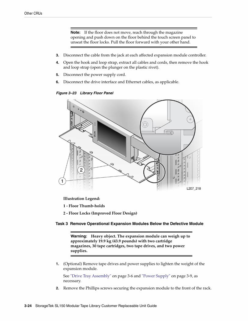
Note: If the floor does not move, reach through the magazineopening and push down on the floor behind the touch screen panel tounseat the floor locks. Pull the floor forward with your other hand.
Other CRUs
3-24 StorageTek SL150 Modular Tape Library Customer Replaceable Unit Guide
3. Disconnect the cable from the jack at each affected expansion module controller.
4. Open the hook and loop strap, extract all cables and cords, then remove the hookand loop strap (open the plunger on the plastic rivet).
5. Disconnect the power supply cord.
6. Disconnect the drive interface and Ethernet cables, as applicable.
Figure 3–23 Library Floor Panel
Illustration Legend:
1 - Floor Thumb-holds
2 - Floor Locks (Improved Floor Design)
Task 3 Remove Operational Expansion Modules Below the Defective Module
Warning: Heavy object. The expansion module can weigh up toapproximately 19.9 kg (43.9 pounds) with two cartridgemagazines, 30 tape cartridges, two tape drives, and two powersupplies.
1. (Optional) Remove tape drives and power supplies to lighten the weight of theexpansion module.
See "Drive Tray Assembly" on page 3-6 and "Power Supply" on page 3-9, asnecessary.
2. Remove the Phillips screws securing the expansion module to the front of the rack.
Other CRUs
Removal and Replacement 3-25
3. Grasp the module, pull the module forward until the break in the flange is visible,lower the front of the module, pull the module free from the one above it, andaway from the rack.
4. Set the module down and away from the front of the rack.
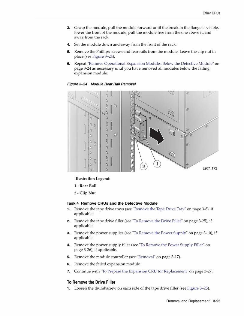
5. Remove the Phillips screws and rear rails from the module. Leave the clip nut inplace (see Figure 3–24).
6. Repeat "Remove Operational Expansion Modules Below the Defective Module" onpage 3-24 as necessary until you have removed all modules below the failingexpansion module.
Figure 3–24 Module Rear Rail Removal
Illustration Legend:
1 - Rear Rail
2 - Clip Nut
Task 4 Remove CRUs and the Defective Module1. Remove the tape drive trays (see "Remove the Tape Drive Tray" on page 3-8), if
applicable.
2. Remove the tape drive filler (see "To Remove the Drive Filler" on page 3-25), ifapplicable.
3. Remove the power supplies (see "To Remove the Power Supply" on page 3-10), ifapplicable.
4. Remove the power supply filler (see "To Remove the Power Supply Filler" onpage 3-26), if applicable.
5. Remove the module controller (see "Removal" on page 3-17).
6. Remove the failed expansion module.
7. Continue with "To Prepare the Expansion CRU for Replacement" on page 3-27.
To Remove the Drive Filler1. Loosen the thumbscrew on each side of the tape drive filler (see Figure 3–25).

Other CRUs
3-26 StorageTek SL150 Modular Tape Library Customer Replaceable Unit Guide
2. Grasp the captive screws and pull the filler toward you.
3. Remove the filler from the drive slot and set it aside. You will install the filler inthe CRU at a later time.
4. Return to Step 4 of "Remove CRUs and the Defective Module".
Figure 3–25 Tape Drive Filler
Illustration Legend:
1 - Drive Filler Thumbscrews
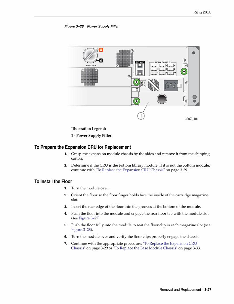
To Remove the Power Supply Filler1. Hook your finger in the hole of the power supply filler (see Figure 3–26).
2. Pull the filler from the power supply slot and set it aside.
3. Continue with "To Prepare the Expansion CRU for Replacement".
Other CRUs
Removal and Replacement 3-27
Figure 3–26 Power Supply Filler
Illustration Legend:
1 - Power Supply Filler
To Prepare the Expansion CRU for Replacement1. Grasp the expansion module chassis by the sides and remove it from the shipping
carton.
2. Determine if the CRU is the bottom library module. If it is not the bottom module,continue with "To Replace the Expansion CRU Chassis" on page 3-29.
To Install the Floor1. Turn the module over.
2. Orient the floor so the floor finger holds face the inside of the cartridge magazineslot.
3. Insert the rear edge of the floor into the grooves at the bottom of the module.
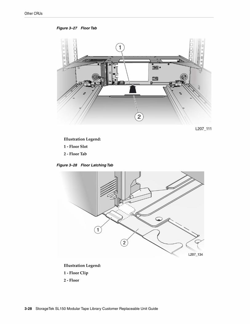
4. Push the floor into the module and engage the rear floor tab with the module slot(see Figure 3–27).
5. Push the floor fully into the module to seat the floor clip in each magazine slot (seeFigure 3–28).
6. Turn the module over and verify the floor clips properly engage the chassis.
7. Continue with the appropriate procedure: "To Replace the Expansion CRUChassis" on page 3-29 or "To Replace the Base Module Chassis" on page 3-33.
Other CRUs
3-28 StorageTek SL150 Modular Tape Library Customer Replaceable Unit Guide
Figure 3–27 Floor Tab
Illustration Legend:
1 - Floor Slot
2 - Floor Tab
Figure 3–28 Floor Latching Tab
Illustration Legend:
1 - Floor Clip
2 - Floor

Other CRUs
Removal and Replacement 3-29
To Replace the Expansion CRU Chassis
Task 1 Installation1. Lift the expansion module by the sides.
2. Align the flanges at the rear of the expansion module with the grooves in thelower front edges of the library module.
3. Push the expansion module a few inches into the library.
Note: There is a gap in the module flange.
4. Lower the top front edge of the expansion module while slowly pushing it towardthe library.
5. Take care to avoid any contact between the expansion module internal verticalflange and the plastic bezel of the library module (see Figure 3–29).
6. Lift the front edge of the module to level after the internal vertical flange is behindthe face of the installed module. Continue to push the module in until it is about51 mm (2 inches) from the rack front stiles.
7. Locate the expansion module alignment tab and the slot in the library module leftmagazine slot (see Figure 3–30).
8. Push the expansion module in and seat the alignment tab fully in the leftmagazine slot.
9. Attach the expansion module CRU label (upper-left, rear corner inside the scribemarks) if applicable.
Figure 3–29 Avoid Contact with the Operator Panel
Illustration Legend:
1 - Flange (Short Section)
2 - Internal Vertical Flange

Other CRUs
3-30 StorageTek SL150 Modular Tape Library Customer Replaceable Unit Guide
3 - Flange (Long Section)
Figure 3–30 Module Alignment
Illustration Legend:
1 - Alignment Tab
2 - Slot
Task 2 Secure the Module1. Insert the rear rails for each module, and secure them with Phillips screws.
2. Secure the module to the front of the rack with two Phillips screws.
Task 3 Install the CRUs, Fillers, and Magazines in the Replaced ModuleCables and cords are connected as part of CRU installation.
1. Install the module controller (see "To Replace the Module Controller" onpage 3-18).
2. Install the tape drive assembly (see "To Replace the Drive Tray" on page 3-9).
3. Install the tape drive filler (see "To Install the Drive Filler" on page 3-31).
4. Install the power supply (see "To Replace the Power Supply" on page 3-10).
5. Install the power supply filler (see "To Install the Power Supply Filler" onpage 3-31).
6. Insert the cartridge magazines.
Task 4 Install the Remaining Expansion Modules1. Locate the next expansion module for installation (refer to the module number
label on the back of the module).
2. Install the floor if this is the bottom library module (see "To Install the Floor" onpage 3-27).
Other CRUs
Removal and Replacement 3-31
3. Repeat "Installation" on page 3-29 through "Install the CRUs, Fillers, andMagazines in the Replaced Module" until all expansion modules and CRUs areinstalled.
Task 5 Finishing Touches1. Secure the hook and loop strap to the replaced expansion module (close the
plunger of the rivet).
2. Align, dress, and secure cables in the hook and loop straps.
3. Continue with "Power System Behavior" on page 3-35.
To Install the Drive Filler1. Position the tape drive filler with the spring fingers facing up.
2. Grasp the captive screws and guide the filler into the tape drive slot.
3. Tighten both thumbscrews.
4. Return to Step 4 of "Install the CRUs, Fillers, and Magazines in the ReplacedModule".
To Install the Power Supply Filler1. Position the filler with the spring fingers facing up.
2. Insert the tabs on the right side of the filler into the power supply slot until thenotch is near the module frame.
3. Seat the filler notch against the module frame edge.
4. Push the left side of the filler into the power supply slot.
5. Return to Step 6 of "Install the CRUs, Fillers, and Magazines in the ReplacedModule".
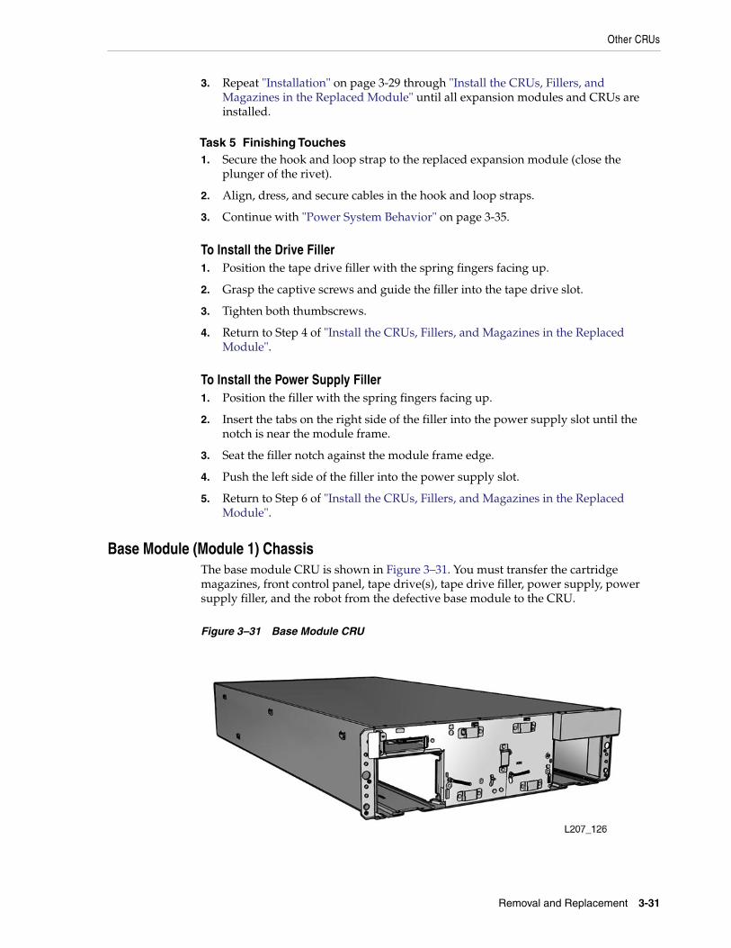
Base Module (Module 1) ChassisThe base module CRU is shown in Figure 3–31. You must transfer the cartridgemagazines, front control panel, tape drive(s), tape drive filler, power supply, powersupply filler, and the robot from the defective base module to the CRU.
Figure 3–31 Base Module CRU
Caution: The robot, front control panel, and base module chassis arecritical to maintaining the product serial number and customersettings. When a replacement is needed for any of these CRUs, youmay replace only one CRU during a single power-down cycle.
Other CRUs
3-32 StorageTek SL150 Modular Tape Library Customer Replaceable Unit Guide
If the library has expansion modules, remove all of the expansion modules to accessthe defective base module.
To Remove the Base Module Chassis
Task 1 Preparation1. Perform "Park and Lock the Robot" on page 3-18.
Note: It is critical for the robot to be parked before proceeding.
2. Remove all modules below the base module (see "To Remove an ExpansionModule" on page 3-23).
Task 2 Remove Base Module Parts for Reuse01. Remove magazines (see "To Remove a Tape Cartridge Magazine" on page 3-4).
2. Remove the Front Control Panel (see "To Remove the Front Control Panel" onpage 3-15).
3. Remove the robot (see "To Remove the Robot" on page 3-18).
Note: Includes removal of the Ethernet cable and the expansioncable(s). Set the expansion cable(s) aside.
4. Remove the tape drive trays (see "To Remove the Drive Tray" on page 3-7).
5. Remove the tape drive filler (see "To Remove the Drive Filler" on page 3-25).
6. Remove the power supplies (see "To Remove the Power Supply" on page 3-10).
7. Remove the power supply filler (see "To Remove the Power Supply Filler" onpage 3-26).
Task 3 Removal
Warning: The base module weighs approximately 12.8 kg (28.3pounds) without magazines, tape drives, power supplies, or therobot CRU. A best practice is to use two persons to lift the unit.
1. Remove the screws securing the base module to the front of the rack.
2. Extract the module from the rack.
Other CRUs
Removal and Replacement 3-33
To Prepare the Base Module CRU for Replacement1. Grasp the base module chassis by the sides and remove it from the shipping
carton.
2. Determine if the CRU is the bottom library module. If it is the bottom module,install the floor (see "To Install the Floor" on page 3-27).
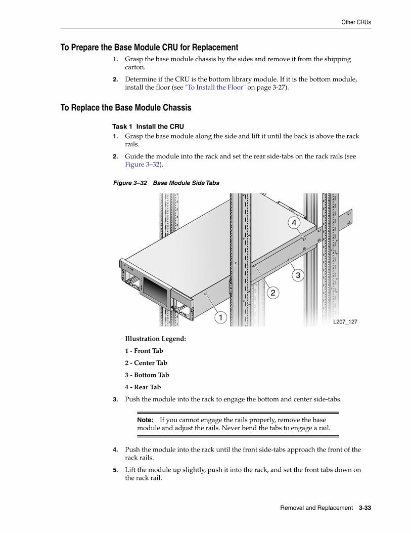
To Replace the Base Module Chassis
Task 1 Install the CRU1. Grasp the base module along the side and lift it until the back is above the rack
rails.
2. Guide the module into the rack and set the rear side-tabs on the rack rails (seeFigure 3–32).
Figure 3–32 Base Module Side Tabs
Illustration Legend:
1 - Front Tab
2 - Center Tab
3 - Bottom Tab
4 - Rear Tab
3. Push the module into the rack to engage the bottom and center side-tabs.
Note: If you cannot engage the rails properly, remove the basemodule and adjust the rails. Never bend the tabs to engage a rail.
4. Push the module into the rack until the front side-tabs approach the front of therack rails.
5. Lift the module up slightly, push it into the rack, and set the front tabs down onthe rack rail.
Other CRUs
3-34 StorageTek SL150 Modular Tape Library Customer Replaceable Unit Guide
6. Secure the base module to the rack with screws (put one in a few turns then theother screw and tighten both).
Task 2 Install the Base Module CRUsCables and cords are installed as part of the CRU replacement procedures.
1. Install the robot (see "To Replace the Robot" on page 3-22).
2. Install the tape drive trays (see "To Replace the Drive Tray" on page 3-9).
3. Install the tape drive filler (see "To Install the Drive Filler" on page 3-31).
4. Install the power supplies (see "To Replace the Power Supply" on page 3-10).However, do not connect the power supply cable now.
5. Install the power supply filler (see "To Install the Power Supply Filler" onpage 3-31).
6. Install the Front control panel (see "To Replace the Front Control Panel" onpage 3-16).
Task 3 Install the Expansion Modules1. Locate Module 2.
2. Determine if this is the bottom library module. Install the library floor in thebottom module (see "To Install the Floor" on page 3-27).
3. Install the module (see "To Replace the Expansion CRU Chassis" on page 3-29).
Note: CRUs, drive cables, and module interconnect cables areinstalled during replacement of the expansion module.
4. Locate the next module and repeat step 2 and step 3 as necessary until all modulesare in place.
5. Install cartridge magazines (see "To Replace a Tape Cartridge Magazine" onpage 3-6) in all modules.
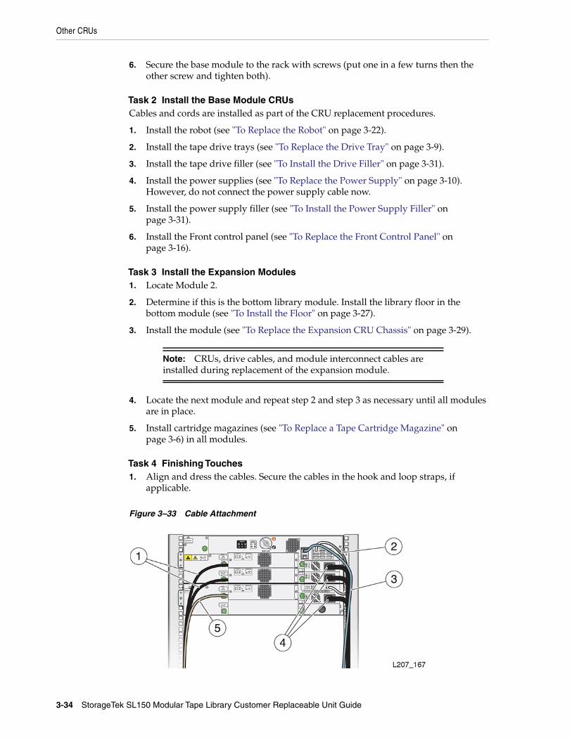
Task 4 Finishing Touches1. Align and dress the cables. Secure the cables in the hook and loop straps, if
applicable.
Figure 3–33 Cable Attachment
Power System Behavior
Removal and Replacement 3-35
Illustration Legend:
1 - Tape Drive With Fibre Channel Cable
2 - Expansion Module Cable
3 - Ethernet Cable
4 - Power Supply Cord
5 - Tape Drive With SAS Cable
2. Connect the power cord to each installed power supply.
3. Continue with Power System Behavior.
Power System BehaviorThe behavior of the SL150 library when AC power is applied to the system powersupplies depends on how the tape library was powered down from the previouspowered-up state. The system BIOS is set to recall the last power state from AC loss(such as a utility power outage, removal of the AC power cord, or powering off a PDUor power strip).
When AC power is restored, the system turns on for about 4 seconds while the systemBIOS determines the library power state when AC was lost.
■ If the tape library was powered up when AC was lost, it remains in the powered-onstate and the boot sequence starts.
■ If the tape library was powered down when AC was lost, it returns to thepowered-down state about 4 seconds after AC power restoration.
A controlled powered-down is performed from the SL150 remote management interfaceor physical library power button (the touch screen GUI is also involved). If power islost after a controlled power-down, the BIOS resets to power on for about 4 secondswhen AC power is restored. The tape library returns to the powered-off state until thepower button is pressed to apply power to the tape library.
A forced power-down of the tape library is performed by pressing and holding thepower button until the library powers down (approximately 10 seconds). If power islost after a forced power-down, the library does not perform the BIOS power on for 4seconds after AC power restoration. The tape library remains in the powered-downstate until the power button is pressed to apply power to the tape library.
To Power-on the Library1. Make sure the robot is not locked.
2. Make sure the floor is installed in the bottom library module.
3. Press the power switch on the base module to initiate a restart, if necessary.
Caution: Do not manually remove a cartridge magazine while thelibrary is performing the restart. Perform a manual magazineremoval only when the library is operational and offline.
See Appendix A, "Startup" for a description of the process. Library initializationoccurs during startup and includes movement of the robot to determine thenumber of modules and tape drives in the library. If library initialization fails, thetape drive ports are not enabled.
Note: In a bridged library, the host will not be able to see the libraryif the bridged drive ports are not enabled. Perform troubleshootingprocedures in the user’s guide to resolve a bridged drive problem.
Power System Behavior
3-36 StorageTek SL150 Modular Tape Library Customer Replaceable Unit Guide
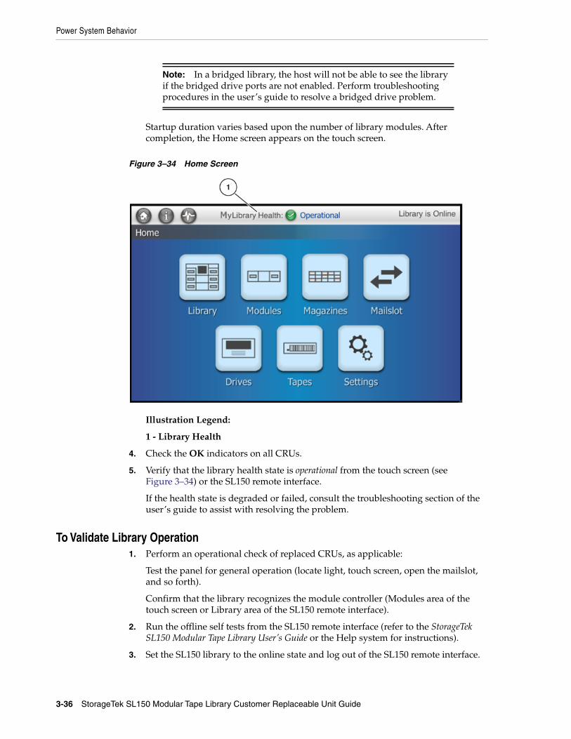
Startup duration varies based upon the number of library modules. Aftercompletion, the Home screen appears on the touch screen.
Figure 3–34 Home Screen
Illustration Legend:
1 - Library Health
4. Check the OK indicators on all CRUs.
5. Verify that the library health state is operational from the touch screen (seeFigure 3–34) or the SL150 remote interface.
If the health state is degraded or failed, consult the troubleshooting section of theuser’s guide to assist with resolving the problem.
To Validate Library Operation1. Perform an operational check of replaced CRUs, as applicable:
Test the panel for general operation (locate light, touch screen, open the mailslot,and so forth).
Confirm that the library recognizes the module controller (Modules area of thetouch screen or Library area of the SL150 remote interface).
2. Run the offline self tests from the SL150 remote interface (refer to the StorageTekSL150 Modular Tape Library User’s Guide or the Help system for instructions).
3. Set the SL150 library to the online state and log out of the SL150 remote interface.
Note: After CRU replacement, run application commands toensure that the library and drive applications are synchronized. Seeyour host tape application documentation for guidance.
CRU Return
Removal and Replacement 3-37
CRU ReturnReturn the robot and tape drive tray CRUs to Oracle. Instructions should have beenprovided regarding the process to return the specific CRU.
Dispose of all other CRUs or recycle them, as appropriate.

CRU Return
3-38 StorageTek SL150 Modular Tape Library Customer Replaceable Unit Guide
A
Startup A-1
AStartup
The SL150 library is typically started up when power is applied (the power cord isplugged in or the external power is switched on). If the library was manually powereddown (from the front panel power switch or the shutdown function of the remotemanagement interface), pressing the front panel power switch starts the library.
During library startup, the following steps are performed:
1. The robot is unparked.
2. The hand fully retracts.
3. The robot moves from the top to the bottom of the entire library. By starting at thetop and moving down one module at a time, the robot determines the order of themodules.
4. The wrist sweeps through its full range of motion.
5. The hand moves through the full track range.
6. The reach mechanism extends and retracts.
7. Magazines are latched.
8. A full library audit is performed.
You can observe the progress of a library audit from the Library view in a webbrowser. Tape slots that the library has not audited are greyed-out while auditedtape slots are active (a barcode icon is present in the slot). When you move thecursor over the active slot the tape location and barcode information is shown. Ifthe barcode information has a value of unreadable, the barcode label is out ofspecification, damaged, or it does not exist.
Be aware that the barcode icon is a facsimile and does not represent the actualcartridge barcode.
When the audit completes and all drives are ready, the library is operational.

A-2 StorageTek SL150 Modular Tape Library Customer Replaceable Unit Guide
Glossary-1
Glossary
This glossary defines terms and abbreviations in this publication.
Some of the definitions are taken from other glossaries. The letters in the parenthesesthat follow some definitions indicate the source of the definition:
(A) The American National Standard Dictionary for Information Systems, ANSIX3.172-1990, copyright 1990 by the American National Standards Institute (ANSI).
(E) The ANSI/Electronic Industries Association (EIA) Standard-440-A, Fiber OpticTerminology.
(I) The Information Technology Vocabulary, developed by Subcommittee 1, JointTechnical Committee 1, of the International Organization for Standardization andInternational Electro-technical Commission (ISO/IEC/JTC1/SC1).
(IBM) The IBM Dictionary of Computing, copyright 1994 by IBM.
(T) Draft international standards committee drafts, and working papers beingdeveloped by the ISO/IEC/JTC1/SC1.
alphanumeric
A character or group of characters that identifies a register, a particular part of storage,or some other data source or destination. (A).
arm
The robotic assembly that is lowered between the columns of tapes. The arm hangs onfour wires from the Z mechanism. The arm includes the hand, the rails the hand rideson, the track motor that moves the hand along the rails, and the KLT card.
audit
The process of recording the location of all tapes in a library.
base chassis
The sheet metal and plastic chassis that makes up the framework of the base module(Module 1).
base module
The smallest, fully functional library consisting of the base chassis with the midplane,robot, front control panel, mailslot, one or two power supplies, up to two half-heightLTO Ultrium tape drives, left magazine, and right magazine.
cartridge
A storage device that consists of magnetic tape on a supply reel in a protectivehousing. The spine of the cartridge usually contains a label listing the volume

cell
Glossary-2
identification number. Also called tape, tape cartridge, or tape volume.
cell
See slot.
cleaning cartridge
A tape cartridge that contains special material to clean the tape path in a transport ordrive. LTO Ultrium cleaning cartridge labels have a CLN prefix and a CU mediaidentifier.
configuration
The manner in which the hardware and software of an information processing systemis organized and interconnected. (T)
data cartridge
A term used to distinguish a cartridge onto which a tape drive may write data.
diagnostics
Pertaining to the detection and isolation of errors in programs and faults inequipment.
dismount
To remove a tape from a drive.
drive
A drive controls the movement of the tape and records or reads the data on the tape asdesired by the customer (see tape drive).
drive cleaning
The device feature that uses a cleaning cartridge to clean a tape drive.
drive slot
The space in the library where the tape drive resides.
drive tray
See tape drive.
dynamic host configuration protocol (DHCP)
A network protocol that enables a server to automatically assign an IP address todevices on a network. DHCP assigns a number dynamically from a defined range ofnumbers for a given network.
encryption
The process of changing data into a form that cannot be read until it is deciphered,protecting the data from unauthorized access and use.
Ethernet
A local-area, packet-switched bus topology that enables the connection of severalcomputer systems. The Ethernet architecture is similar to the IEEE 802.3 standard.
gripper
Glossary-3
expanded mailsot
An optional library configuration to increase the capacity of the Mailslot from four to19 cartridges. A logical entity containing four slots in the Standard Mailslot plus 15slots in the Base Module right magazine (the Mailslot Expansion).
expansion cable
A cable used to connect modules 2–10 to the base module (Module 1). Each end of thecable has a USB A style connector.
expansion chassis
The sheet metal and plastic chassis that makes up the framework for Module 2–10.
expansion module
A module that can be added to the bottom of an existing library to increase its capacityfor drives and tape cartridges (tapes). The module consists of the expansion chassis, amodule controller, up to two power supplies, up to two half-height LTO Ultrium tapedrives, a left magazine, and a right magazine. The expansion module connects to thebase module by an expansion cable.
export
The action in which the device places a cartridge into the mailslot so that the operatorcan remove the cartridge. Also called eject.
FC
See Fibre Channel.
fiber optics
The branch of optical technology concerned with the transmission of radiant powerthrough fibers made of transparent materials such as glass, fused silica, and plastic. (E)
fiber-optic cable
A cable made of ultra-thin glass or silica fibers which can transmit data using pulses oflaser light. Fiber-optic cables have several advantages over copper cables: they havemuch less signal loss; they allow information to be transmitted at higher speeds andover longer distances; they are not affected by external electrical noise; and they arebetter for transmissions which require security.
Fibre Channel
The National Committee for Information Technology Standards standard that definesan ultrahigh-speed, content-independent, multilevel data transmission interface thatsupports multiple protocols simultaneously. Fibre Channel supports connectivity tomillions of devices over copper and fiber-optic physical media and provides the bestcharacteristics of both networks and channels over diverse topologies.
front control panel
An assembly mounted on the front of the base chassis. It includes the touch screenoperator panel, various LEDs and switches, and associated electronics.
get
An activity in which a robot obtains a cartridge from a slot or drive.
gripper
The portion of the hand assembly that grasps and holds a cartridge.

GUI
Glossary-4
GUI
Graphical user interface. Software that allows the user to control the device throughvisual screens.
hand
The robotic mechanism that grabs tape cartridges and moves them between slots andthe drive. It is a component of the arm. The hand has a reach mechanism that gets tapecartridges from slots or drives and puts them into slots or drives. The hand also has awrist mechanism that rotates the hand to allow it to reach cartridges on either side orthe drives at the back of the library.
hardware
All or part of the physical components of an information processing system, such ascomputers or peripheral devices. (T) (A)
HBA
See host bus adapter.
host bus adapter (HBA)
A circuit installed in a multi-platform host or device that interfaces between the deviceand the bus.
host computer
In a computer network, a computer that usually performs network control functionsand provides end users with services such as computation and database access. (T)
host bus adapter (HBA)
A circuit installed in a multi-platform host or device that interfaces between the deviceand the bus.
host interface
An interface between a network and host computer. (T)
import
The process of bringing a cartridge into the library from the mailslot. Also called enter.
indicator
A device that provides a visual or other indication of the existence of a defined state.(T)
initialization
The operations required for setting a device to a starting state, before the use of a datamedium, or before implementation of a process. (T)
interface
Hardware, software, or both, that links systems, programs, or devices. (IBM)
inventory
See audit.
LC connector
A standard fiber-optic cable connector for Fibre Channel data transfer.
Module 1
Glossary-5
LED
Light emitting diode. An electronic device that lights up when electricity is passedthrough it.
left magazine
A plastic assembly containing 15 tape slots that can be inserted into the left side (asviewed from the front) of Modules 1–10. Left magazines and right magazines are notinterchangeable.
library
A robotic system that stores, moves, mounts, and dismounts tape cartridges that areused in data read or write operations.
LTO
An acronym for Linear Tape-Open technology. An “open format” technology, whichmeans that users will have multiple sources of products and media.
LUN
Logical Unit Number. An address for a component of a SCSI device. In this device, thehost computer sends the SCSI commands for the library to LUN 1 of the master tapedrive and sends SCSI commands for the tape drive itself to LUN 0.
MAC address
The media access control address is a unique identifier assigned to devices forcommunication on a physical network.
magnetic tape
A tape with a magnetizable layer on which data can be stored. (T)
magnetic tape drive
A mechanism for controlling the movement of magnetic tape, commonly used to movemagnetic tape past a read head or write head, or to allow automatic rewinding. (I) (A)
mailslot
The Standard Mailslot is a plastic and metal assembly located in the upper right cornerof the base chassis used to enter tapes into the library and to remove tapes from thelibrary. Previous StorageTek libraries called this a CAP (Cartridge Access Port).
mailslot expansion
A term describing the Base Module right magazine (the magazine immediately belowthe Standard Mailslot) when the library has the expanded mailslot configuration. Themailslot capacity expands from four cartridges (Standard Mailslot) to 19 cartridges.
midplane
A card mounted in the base chassis or expansion chassis that is behind the tape slotsand in front of the tape drives. Other cards connect to it either by direct connection orby a cable.
Module 1
See base module.
module controller
Glossary-6
module controller
A card inserted into the back of Modules 2–10 that controls the operation of themodule. It is connected to the robot by an expansion cable.
Module X (2 through 10)
See expansion module.
mount
To place a tape in a drive and make it accessible to the host system.
multimode fiber
An optical fiber designed to carry multiple signals, distinguished by frequency orphase, at the same time.
net mask
A 32-bit, or 4-byte number, in dotted decimal format (typically written as fournumbers separated by periods, such as 255.255.0.0 or 255.255.255.0) that is applied toan IP address to identify the network and node address of a host or router interface.(Synonymous with subnet mask.)
network
An arrangement of nodes and branches that connects data processing devices to oneanother through software and hardware links to facilitate information interchange.
offline
Neither controlled by, nor communicating with, a computer. (IBM)
online
Pertaining to the operation of a functional unit when under the direct control of thecomputer. (T)
operator panel
A component of the front control panel consisting of a seven inch WVGA color touchscreen.
port
A specific communications end point within a host. A port is identified by a portnumber. (IBM) (2) In Fibre Channel, an access point in a device where a link attaches.
power supply
An AC to DC power supply that mounts into the rear of a module Module (1–10).Referred to as top power supply or bottom power supply when referring to a powersupply installed in a specific module.
power supply filler
A metal frame that slides into a power supply slot when a power supply will not beused in that slot.
put
An activity in which a robot places a cartridge into a slot or drive.
tape drive
Glossary-7
release
A distribution of a new product or new function and fixes for an existing product.(IBM)
right magazine
A plastic assembly containing 15 tape slots that can be inserted into the right side (asviewed from the front) of Modules 1–10. Right magazines and left magazines are notinterchangeable.
robot
An assembly that incorporates the bulk of the base module electronics and the roboticcomponents. This assembly is a combination of mechanical components, electronics,and a sheet metal housing. It is located at the top of the base chassis and incorporatesthe arm, Z mechanism, a CPU board, plus the KLC and KLZ cards.
SAS
Serial Attached SCSI. A computer bus technology and serial communication protocolfor direct attached storage devices, including disk drives and high-performance tapedrives.
SCSI
Small Computer System Interface. A standard interface and command set fortransferring data between mass storage and other devices. The host computer usesSCSI commands to operate the device. Depending on the model, physical connectionbetween the host computer and the tape drive will use a parallel SCSI, SAS, or FibreChannel interface.
SLAAC
Stateless automatic address configuration. The process of a host generating its ownaddress by using a combination of locally available information, such as a MACaddress, and information that is advertised by routers.
slot
An empty location into which something else may be placed. Most commonly usedwhen referring to the locations in the magazine or mailslot where tape cartridges areplaced. Power supplies and drives are also placed in slots.
switch
In Fibre Channel technology, a device that connects Fibre Channel devices together ina fabric.
tape
Also known as cartridge, tape cartridge, tape volume, volume, or cassette.
tape cartridge
A container holding magnetic tape that can be processed without separating the tapefrom the container. The device uses data and cleaning cartridges. These cartridges arenot interchangeable. See cartridge.
tape drive
An electro-mechanical device that moves magnetic tape and includes mechanisms forwriting and reading data to and from the tape. The drive is mounted into a proprietarytray (sometimes called a sled).
tape drive filler
Glossary-8
tape drive filler
A metal frame that slides into a tape drive slot when a tape drive will not be used inthat slot.
Terabyte
A unit of storage, abbreviated T or TB, equal to 1,024 Gigabytes.
U
A measure of chassis height. 1U in rack measurement is 44.45 millimeters (1.75 inches).
USB
Universal Serial Bus. A serial bus standard used to interface devices.
World Wide Name
A unique identifier in a Fibre Channel or SAS storage network. The first three bytesare derived from an IEEE Organizationally Unique Identifier (OUI), which defines themanufacturer or vendor. The remaining five bytes are assigned by the vendor.
WORM
An acronym for Write Once Read Many times, a class of recording systems that allowrecording and adding data, but not altering recorded data.
wrist
A component of the hand assembly that rotates the hand horizontally.
Z mechanism
The robotic assembly mounted at the back of the robot that raises and lowers the arm.The Z mechanism includes a motor, gears, the bullwheel, and the wires and pulleysthat hold the arm. As the motor turns, the bullwheel rotates and extends or retracts thewires to lower or raise the arm.
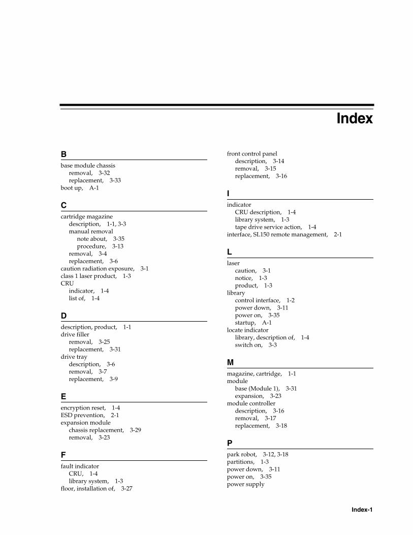
Index-1
Index
Bbase module chassis
removal, 3-32replacement, 3-33
boot up, A-1
Ccartridge magazine
description, 1-1, 3-3manual removal
note about, 3-35procedure, 3-13
removal, 3-4replacement, 3-6
caution radiation exposure, 3-1class 1 laser product, 1-3CRU
indicator, 1-4list of, 1-4
Ddescription, product, 1-1drive filler
removal, 3-25replacement, 3-31
drive traydescription, 3-6removal, 3-7replacement, 3-9
Eencryption reset, 1-4ESD prevention, 2-1expansion module
chassis replacement, 3-29removal, 3-23
Ffault indicator
CRU, 1-4library system, 1-3
floor, installation of, 3-27
front control paneldescription, 3-14removal, 3-15replacement, 3-16
Iindicator
CRU description, 1-4library system, 1-3tape drive service action, 1-4
interface, SL150 remote management, 2-1
Llaser
caution, 3-1notice, 1-3product, 1-3
librarycontrol interface, 1-2power down, 3-11power on, 3-35startup, A-1
locate indicatorlibrary, description of, 1-4switch on, 3-3
Mmagazine, cartridge, 1-1module
base (Module 1), 3-31expansion, 3-23
module controllerdescription, 3-16removal, 3-17replacement, 3-18
Ppark robot, 3-12, 3-18partitions, 1-3power down, 3-11power on, 3-35power supply
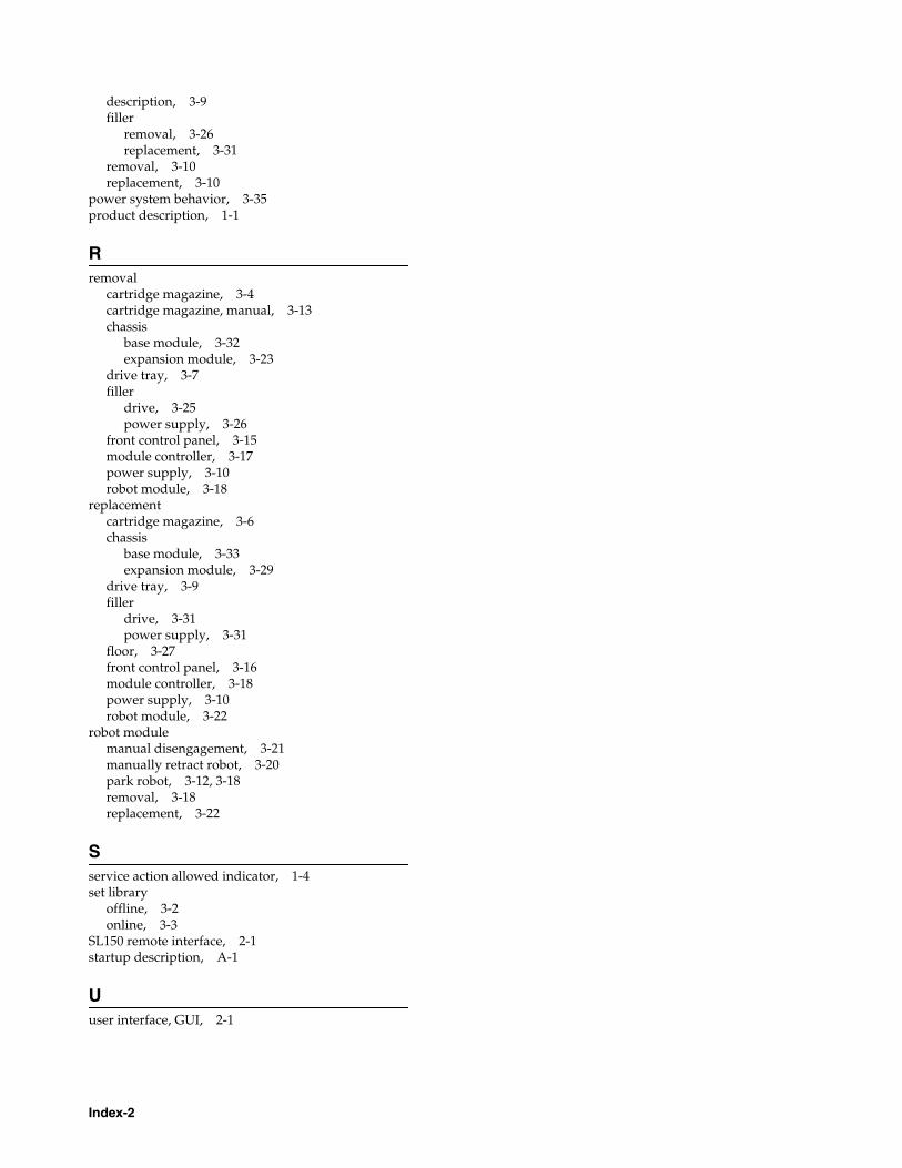
Index-2
description, 3-9filler
removal, 3-26replacement, 3-31
removal, 3-10replacement, 3-10
power system behavior, 3-35product description, 1-1
Rremoval
cartridge magazine, 3-4cartridge magazine, manual, 3-13chassis
base module, 3-32expansion module, 3-23
drive tray, 3-7filler
drive, 3-25power supply, 3-26
front control panel, 3-15module controller, 3-17power supply, 3-10robot module, 3-18
replacementcartridge magazine, 3-6chassis
base module, 3-33expansion module, 3-29
drive tray, 3-9filler
drive, 3-31power supply, 3-31
floor, 3-27front control panel, 3-16module controller, 3-18power supply, 3-10robot module, 3-22
robot modulemanual disengagement, 3-21manually retract robot, 3-20park robot, 3-12, 3-18removal, 3-18replacement, 3-22
Sservice action allowed indicator, 1-4set library
offline, 3-2online, 3-3
SL150 remote interface, 2-1startup description, A-1
Uuser interface, GUI, 2-1


![[]StorageTek SL150 ModularTape Library Installation … SL150 Modular Tape Library Installation Manual E28647-14 ... Change the Default Password](https://img.pdfslide.net/doc/110x75/5addfc987f8b9aa5088d90fd/storagetek-sl150-modulartape-library-installation-sl150-modular-tape-library.jpg)


![StorageTek SL150 Modular Tape Library - InstallationshandbuchDie StorageTek SL150 Modular Tape Library von Oracle ist eine 3 HE (133,4 mm [5,25 Zoll]) bis 21 HE (933,5 mm [36,75 Zoll])](https://img.pdfslide.net/doc/110x75/613b370bf8f21c0c8268e004/storagetek-sl150-modular-tape-library-installationshandbuch-die-storagetek-sl150.jpg)