Embed Size (px)
Citation preview
1
CUTOUT 6
Manual
2
Publication Details
This User Manual is protected under copyright.
All rights to the reprinting and reproduction of this manual, in its original or translat-
ed form, are reserved. Specific portions of this work may neither be reproduced—
whether through the process of photocopying, scanning and printing to microfilm, or
any other—nor copied, altered or duplicated in any form for further purposes, in-
cluding the use in teaching programs or lessons, without the company’s express
written consent to do so otherwise.
Disclaimer: The company takes no responsibility for damages that occur while using
this software, whether that be in the form of personal, material or capital damages
directly or indirectly linked to the use of the Software. Additionally, the company
assumes no liability for potential technical errors or for the correctness of the pro-
vided information.
Further References: Microsoft, MS and MS-DOS are registered trademarks and Win-
dows is a label of the Microsoft Corporation in the USA and other countries.
© 2016 Franzis Verlag, Haar bei München
Innovations, errors and misprints reserved.
3
Content
I Introduction .................................................................................... 6
I.1 Album Mode ............................................................................. 6
II Quick Introduction into Object Cropping .................................... 8
II. 1. Inside/Outside Edge Matting ............................................... 10
II.2 Chromakey Matting ............................................................... 19
II.3 Cropping using Object Contours ............................................ 23
III Optimizing Results using Matting Tools .................................. 30
III.1 Chromakey Matting Optimization ........................................ 30
III.1.1 Settings and Parameters ................................................ 30
III.1.2 Matting Tools ................................................................. 38
III.1.3 Allocating Regions to the Foreground/Background ....... 41
III.2 Inside / Outside Edge Matting Optimization ........................ 49
III.2.1 Settings and Parameters ................................................ 49
III.2.2 Cropping Intermediate Areas of an Object using the Edge
Tool .......................................................................................... 55
III.2.3 Syringe Tool for Detail Enhancement ............................ 57
III.2.4 Matting Tools ................................................................. 60
III.2.5 Allocating Regions to the Foreground/Background ....... 62
III.3 Additional Tips for cropping complicated Objects ................ 72
III.3.1 Close to the edge or farther out? .................................. 72
III.3.2 Cropping Complicated Objects ...................................... 73
IV Digital Matting: Good to Know .................................................. 74
4
IV.1 General Information concerning Matting Technology ......... 75
IV.2 Chromakey Matting .............................................................. 76
IV.3 Inside/Outside Edge Matting ................................................ 77
V The Post-Matting Menu .............................................................. 79
V.1 Changing the Background Image ........................................... 81
V.2 Background Blur .................................................................... 86
V.3 Duplicate to Layer .................................................................. 91
V.4 Layer Separation and Background Deletion .......................... 91
VI Photo Editing .............................................................................. 92
VI.1 Editing Mode – Overview ..................................................... 93
VI.2 Editing Mode – Detailed View .............................................. 95
VI.2.1 Matting .......................................................................... 95
VI.2.2 Transform ...................................................................... 96
VI.2.3 Exposure ...................................................................... 100
VI.2.4 Color ............................................................................ 104
VI.2.5 Enhancement ............................................................... 107
VI.3 Editing Mode – Additional Tips ........................................... 111
VI.3.1 Tools ............................................................................ 111
VI.3.2 Layers ........................................................................... 113
VI.3.3 Areas ............................................................................ 116
VI.3.4 History ......................................................................... 116
VII Program Settings .................................................................... 117
5
VIII Opening and Saving Files ..................................................... 118
Hotline/Support ............................................................................ 121
Copyright ...................................................................................... 122
6
I Introduction
CutOut 6 enables you to separate the foreground from the back-
ground in your photo and edit each individually. Doing this involves
a couple steps. These include selecting regions of the photograph to
be separated (digital matting) and edited. For example, this could
entail the transfer of an object into a different photograph or the
application of Image altering or enhancing effects.
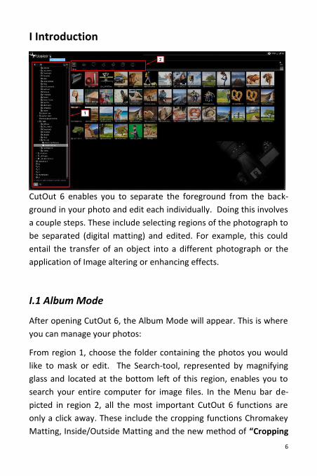
I.1 Album Mode
After opening CutOut 6, the Album Mode will appear. This is where
you can manage your photos:
From region 1, choose the folder containing the photos you would
like to mask or edit. The Search-tool, represented by magnifying
glass and located at the bottom left of this region, enables you to
search your entire computer for image files. In the Menu bar de-
picted in region 2, all the most important CutOut 6 functions are
only a click away. These include the cropping functions Chromakey
Matting, Inside/Outside Matting and the new method of “Cropping
7
using Object Contours”. Different forms of application of these
methods will be introduced in the following chapter.
The Album-View provides a simple and effective way to execute
CutOut 6 functions such as Overview, Sort, Rename, Copy, Paste, or
to insert EXIF-Information. With one right click of the mouse on
your photo, you can view all of the available functions in the Con-
text Menu.
By clicking on the symbols in the upper right-hand corner of your
screen, you can sort your photos according to specific criteria as
well as adjust the icon size of your photos and folders:
8
II Quick Introduction into Object Cropping
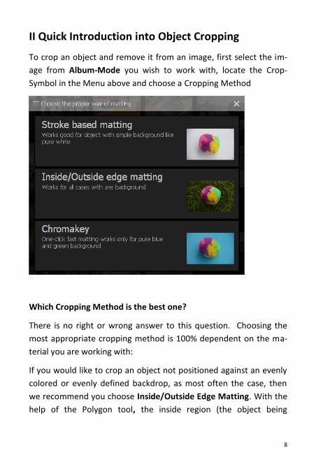
To crop an object and remove it from an image, first select the im-
age from Album-Mode you wish to work with, locate the Crop-
Symbol in the Menu above and choose a Cropping Method
Which Cropping Method is the best one?
There is no right or wrong answer to this question. Choosing the
most appropriate cropping method is 100% dependent on the ma-
terial you are working with:
If you would like to crop an object not positioned against an evenly
colored or evenly defined backdrop, as most often the case, then
we recommend you choose Inside/Outside Edge Matting. With the
help of the Polygon tool, the inside region (the object being
9
cropped) as well as the outside region (the background being cut
out) can be selected, therefore enabling the object to be cropped.
If you would like to crop an object that does possess an evenly col-
ored background (optimally blue or green) which is clearly discern-
able from the object, select the option Chromakey Matting. Well
suited for use would be portraits with monotone backgrounds or
landscape shots against a clear blue sky, for example, from which an
object can be cropped.
The Cropping using object contours method presents itself as an
appropriate solution in cases in which none of the two previously
mentioned methods seem to yield the best result, or when areas
within the cropped object need to be quickly and precisely re-
moved. When this method is chosen, the image is divided into an
array of small puzzle pieces, or segments, all of which can be desig-
nated as either parts of the inside or outside region with just one
mouse-click. Segmented cropping takes into account brightness,
colors and contours to the same degree and yields a clear-cut result.
Using these calculated segments when cropping can also be seen as
the best editing method for those looking to crop objects from im-
ages taken in front of evenly colored backgrounds, not necessarily
in a photo studio that is, such as items to be sold on eBay shot while
lying on the kitchen table. In most cases, the lighting is not always
the best to allow for an effective editing job by use of Chromakey-
Matting alone. Implementing Object Contour Cropping in such a
situation will undoubtedly take your project the furthest. The effec-
tiveness of this method can especially be seen when cropping an
object situated against a white, grey or black backdrop. When work-
ing with rather large images containing many segments, the calcula-
tion may take a little longer.
10
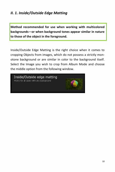
II. 1. Inside/Outside Edge Matting
Method recommended for use when working with multicolored
backgrounds—or when background tones appear similar in nature
to those of the object in the foreground.
Inside/Outside Edge Matting is the right choice when it comes to
cropping Objects from images, which do not possess a strictly mon-
otone background or are similar in color to the background itself.
Select the Image you wish to crop from Album Mode and choose
the middle option from the following window.
11
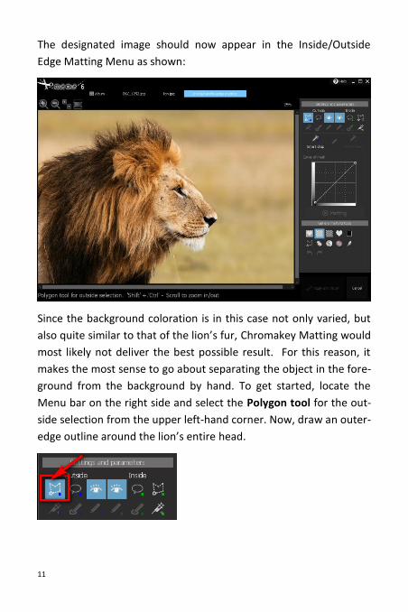
The designated image should now appear in the Inside/Outside
Edge Matting Menu as shown:
Since the background coloration is in this case not only varied, but
also quite similar to that of the lion’s fur, Chromakey Matting would
most likely not deliver the best possible result. For this reason, it
makes the most sense to go about separating the object in the fore-
ground from the background by hand. To get started, locate the
Menu bar on the right side and select the Polygon tool for the out-
side selection from the upper left-hand corner. Now, draw an outer-
edge outline around the lion’s entire head.
12
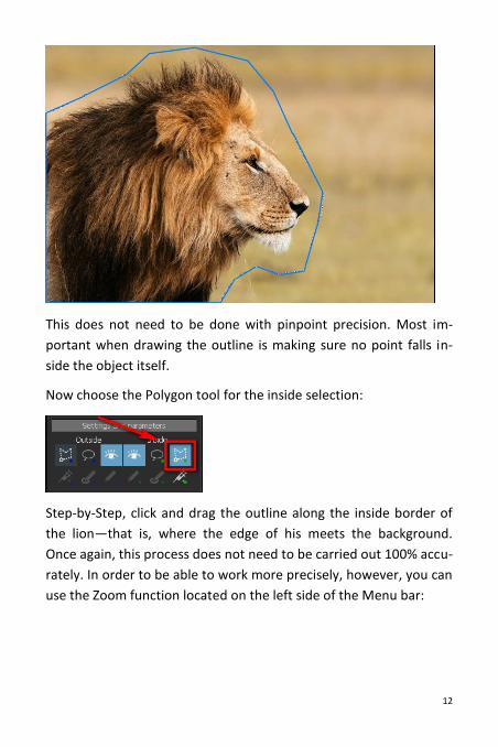
This does not need to be done with pinpoint precision. Most im-
portant when drawing the outline is making sure no point falls in-
side the object itself.
Now choose the Polygon tool for the inside selection:
Step-by-Step, click and drag the outline along the inside border of
the lion—that is, where the edge of his meets the background.
Once again, this process does not need to be carried out 100% accu-
rately. In order to be able to work more precisely, however, you can
use the Zoom function located on the left side of the Menu bar:
13
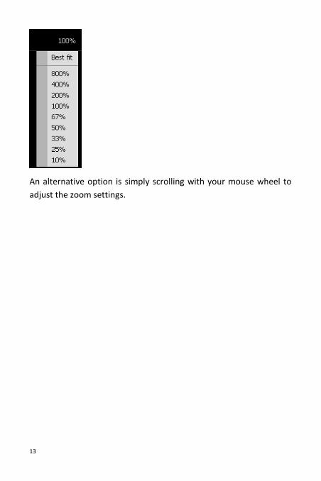
An alternative option is simply scrolling with your mouse wheel to
adjust the zoom settings.
14
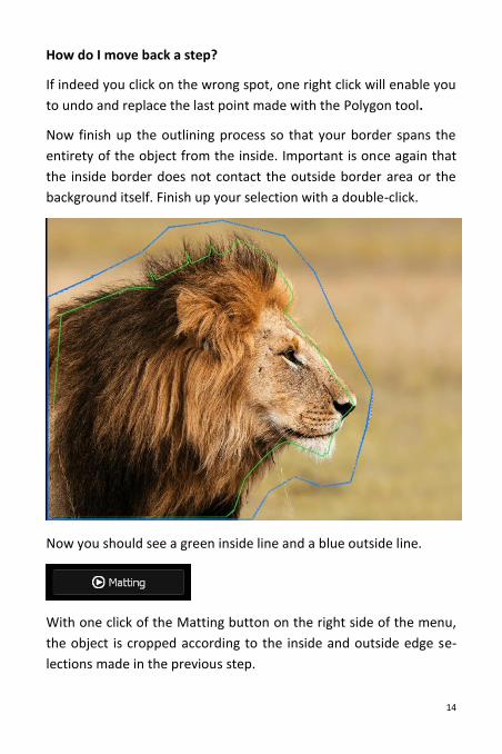
How do I move back a step?
If indeed you click on the wrong spot, one right click will enable you
to undo and replace the last point made with the Polygon tool.
Now finish up the outlining process so that your border spans the
entirety of the object from the inside. Important is once again that
the inside border does not contact the outside border area or the
background itself. Finish up your selection with a double-click.
Now you should see a green inside line and a blue outside line.
With one click of the Matting button on the right side of the menu,
the object is cropped according to the inside and outside edge se-
lections made in the previous step.
15
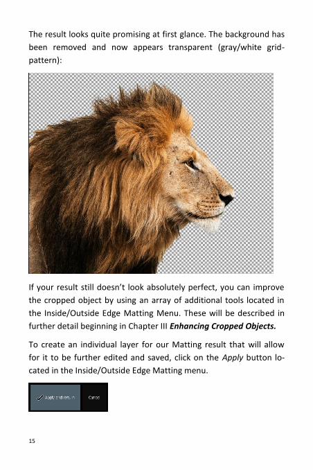
The result looks quite promising at first glance. The background has
been removed and now appears transparent (gray/white grid-
pattern):
If your result still doesn’t look absolutely perfect, you can improve
the cropped object by using an array of additional tools located in
the Inside/Outside Edge Matting Menu. These will be described in
further detail beginning in Chapter III Enhancing Cropped Objects.
To create an individual layer for our Matting result that will allow
for it to be further edited and saved, click on the Apply button lo-
cated in the Inside/Outside Edge Matting menu.
16
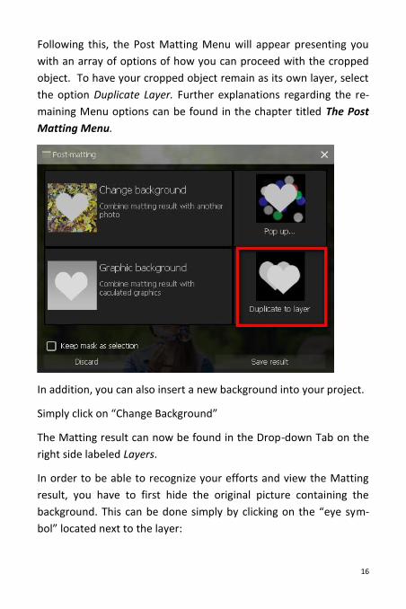
Following this, the Post Matting Menu will appear presenting you
with an array of options of how you can proceed with the cropped
object. To have your cropped object remain as its own layer, select
the option Duplicate Layer. Further explanations regarding the re-
maining Menu options can be found in the chapter titled The Post
Matting Menu.
In addition, you can also insert a new background into your project.
Simply click on “Change Background”
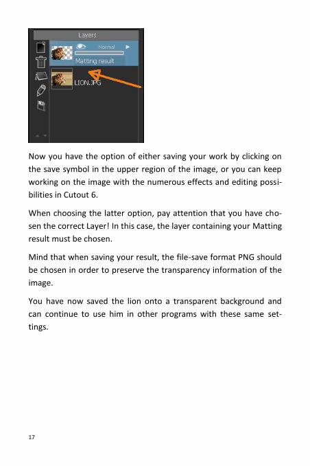
The Matting result can now be found in the Drop-down Tab on the
right side labeled Layers.
In order to be able to recognize your efforts and view the Matting
result, you have to first hide the original picture containing the
background. This can be done simply by clicking on the “eye sym-
bol” located next to the layer:
17
Now you have the option of either saving your work by clicking on
the save symbol in the upper region of the image, or you can keep
working on the image with the numerous effects and editing possi-
bilities in Cutout 6.
When choosing the latter option, pay attention that you have cho-
sen the correct Layer! In this case, the layer containing your Matting
result must be chosen.
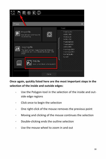
Mind that when saving your result, the file-save format PNG should
be chosen in order to preserve the transparency information of the
image.
You have now saved the lion onto a transparent background and
can continue to use him in other programs with these same set-
tings.
18
Once again, quickly listed here are the most important steps in the
selection of the inside and outside edges:
- Use the Polygon-tool in the selection of the inside and out-
side edge regions
- Click once to begin the selection
- One right-click of the mouse removes the previous point
- Moving and clicking of the mouse continues the selection
- Double-clicking ends the outline selection
- Use the mouse wheel to zoom in and out
19
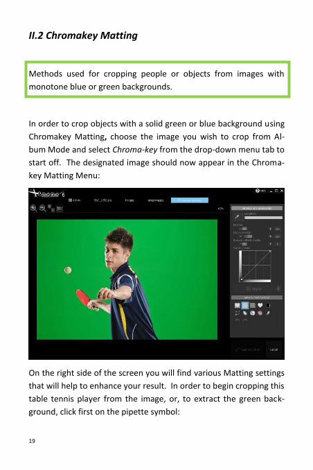
II.2 Chromakey Matting
Methods used for cropping people or objects from images with
monotone blue or green backgrounds.
In order to crop objects with a solid green or blue background using
Chromakey Matting, choose the image you wish to crop from Al-
bum Mode and select Chroma-key from the drop-down menu tab to
start off. The designated image should now appear in the Chroma-
key Matting Menu:
On the right side of the screen you will find various Matting settings
that will help to enhance your result. In order to begin cropping this
table tennis player from the image, or, to extract the green back-
ground, click first on the pipette symbol:
20
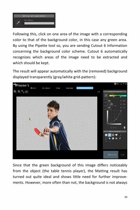
Following this, click on one area of the image with a corresponding
color to that of the background color, in this case any green area.
By using the Pipette tool so, you are sending Cutout 6 Information
concerning the background color scheme. Cutout 6 automatically
recognizes which areas of the image need to be extracted and
which should be kept.
The result will appear automatically with the (removed) background
displayed transparently (gray/white grid-pattern):
Since that the green background of this image differs noticeably
from the object (the table tennis player), the Matting result has
turned out quite ideal and shows little need for further improve-
ments. However, more often than not, the background is not always
21
so clearly defined, thus leading to the need for additional improve-
ments to the Matting result following the first round of edits.
To read more about this step as well as the various tools included in
the Chromakey Menu, please continue to the chapter Chromakey
Matting Optimization.
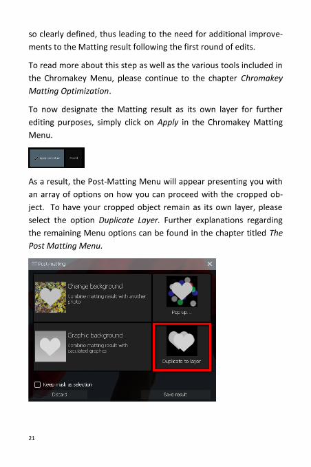
To now designate the Matting result as its own layer for further
editing purposes, simply click on Apply in the Chromakey Matting
Menu.
As a result, the Post-Matting Menu will appear presenting you with
an array of options on how you can proceed with the cropped ob-
ject. To have your cropped object remain as its own layer, please
select the option Duplicate Layer. Further explanations regarding
the remaining Menu options can be found in the chapter titled The
Post Matting Menu.
22
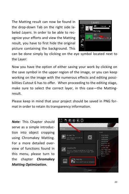
The Matting result can now be found in
the drop-down Tab on the right side la-
beled Layers. In order to be able to rec-
ognize your efforts and view the Matting
result, you have to first hide the original
picture containing the background. This
can be done simply by clicking on the eye symbol located next to
the Layer:
Now you have the option of either saving your work by clicking on
the save symbol in the upper region of the image, or you can keep
working on the image with the numerous effects and editing possi-
bilities Cutout 6 has to offer. When proceeding to the editing stage,
make sure to select the correct layer, in this case—the Matting-
result.
Please keep in mind that your project should be saved in PNG for-
mat in order to retain its transparency information.
Note: This Chapter should
serve as a simple introduc-
tion into object cropping
using Chromakey Matting.
For a more detailed over-
view of functions found in
this menu, please turn to
the chapter Chromakey
Matting Optimization.
23
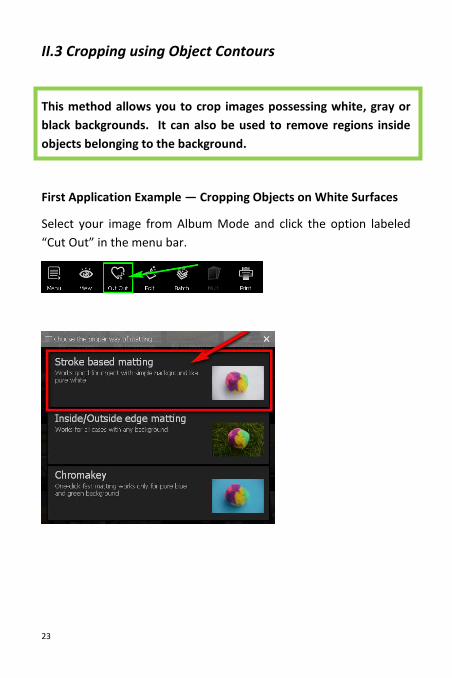
II.3 Cropping using Object Contours
This method allows you to crop images possessing white, gray or
black backgrounds. It can also be used to remove regions inside
objects belonging to the background.
First Application Example — Cropping Objects on White Surfaces
Select your image from Album Mode and click the option labeled
“Cut Out” in the menu bar.
24
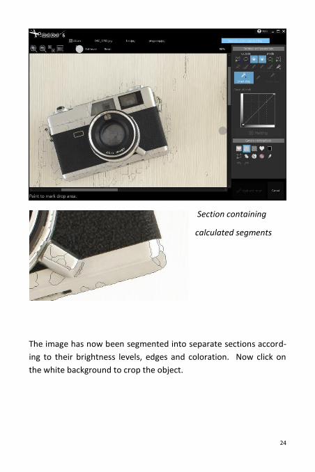
Section containing
calculated segments
The image has now been segmented into separate sections accord-
ing to their brightness levels, edges and coloration. Now click on
the white background to crop the object.
25
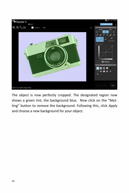
The object is now perfectly cropped. The designated region now
shows a green tint, the background blue. Now click on the “Mat-
ting” button to remove the background. Following this, click Apply
and choose a new background for your object.
26
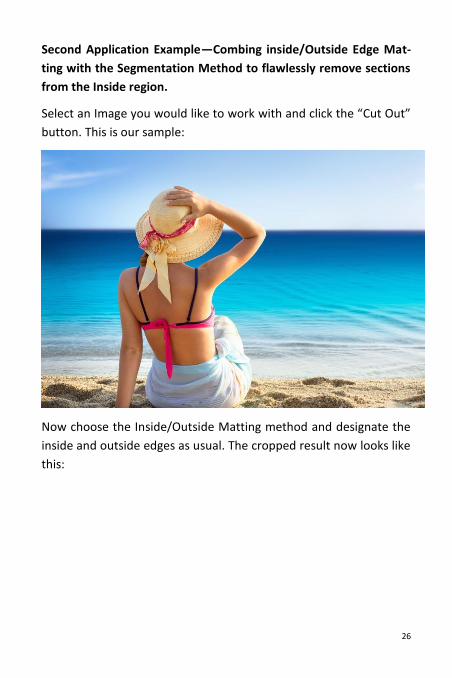
Second Application Example—Combing inside/Outside Edge Mat-
ting with the Segmentation Method to flawlessly remove sections
from the Inside region.
Select an Image you would like to work with and click the “Cut Out”
button. This is our sample:
Now choose the Inside/Outside Matting method and designate the
inside and outside edges as usual. The cropped result now looks like
this:
27
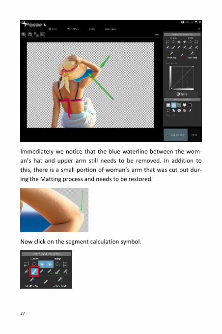
Immediately we notice that the blue waterline between the wom-
an’s hat and upper arm still needs to be removed. In addition to
this, there is a small portion of woman’s arm that was cut out dur-
ing the Matting process and needs to be restored.
Now click on the segment calculation symbol.
28
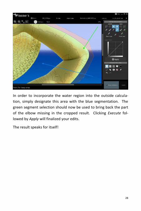
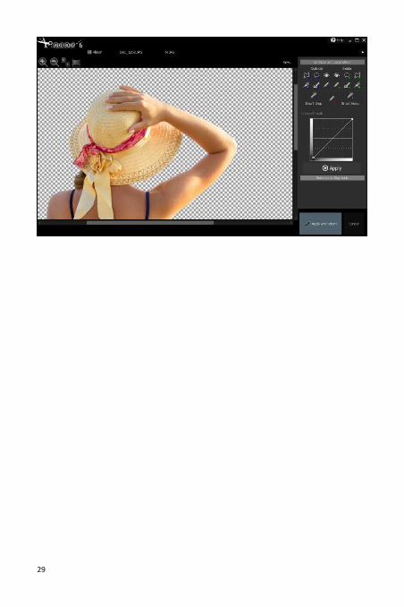
In order to incorporate the water region into the outside calcula-
tion, simply designate this area with the blue segmentation. The
green segment selection should now be used to bring back the part
of the elbow missing in the cropped result. Clicking Execute fol-
lowed by Apply will finalized your edits.
The result speaks for itself!
29
30
III Optimizing Results using Matting Tools
III.1 Chromakey Matting Optimization
III.1.1 Settings and Parameters
For information on when you should use Chromakey Matting and
how to begin cropping an object, please refer to the Quick Introduc-
tion Chapter located at the beginning of the manual. This chapter
deals with complicated cases as well as the optimization of cropping
results through the use of various tools available in Chromakey-
Matting. Should the procedure introduced in the Quick Introduc-
tion Chapter not deliver preferred results, you have an array of ad-
ditional options at your disposal located in the Chromakey Matting
Menu and explained in greater detail here throughout the next
couple pages:
- Feather Brush
Adds individual pixels to the mask and ensures a softer
transition from the foreground to the background.
- Edge Optimization
Optimizes the mask around the edges of cropped objects.
- Reduce Reflected Colors
On some occasions, the background color can be unwant-
edly reflected into the foreground. An example of such a
case would be when a person with white clothing is photo-
graphed in front of a blue backdrop. This can lead to the
white clothing appearing semi-transparent. This option en-
ables you reduce exactly this effect.
- Curve of mask
Improves the mask following the completion of the Mat-
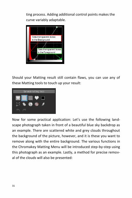
31
ting process. Adding additional control points makes the
curve variably adaptable.
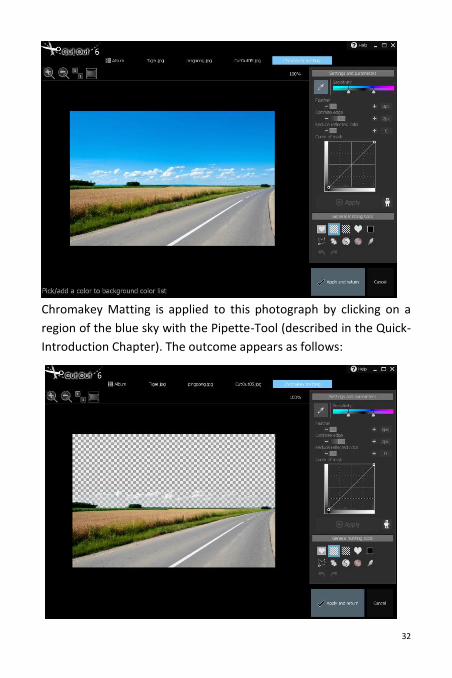
Should your Matting result still contain flaws, you can use any of
these Matting tools to touch up your result:
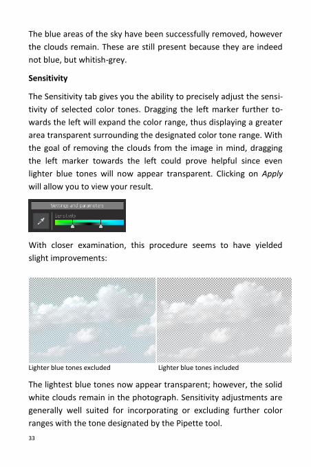
Now for some practical application: Let’s use the following land-
scape photograph taken in front of a beautiful blue sky backdrop as
an example. There are scattered white and grey clouds throughout
the background of the picture, however, and it is these you want to
remove along with the entire background. The various functions in
the Chromakey Matting Menu will be introduced step-by-step using
this photograph as an example. Lastly, a method for precise remov-
al of the clouds will also be presented:
32
Chromakey Matting is applied to this photograph by clicking on a
region of the blue sky with the Pipette-Tool (described in the Quick-
Introduction Chapter). The outcome appears as follows:
33
The blue areas of the sky have been successfully removed, however
the clouds remain. These are still present because they are indeed
not blue, but whitish-grey.
Sensitivity
The Sensitivity tab gives you the ability to precisely adjust the sensi-
tivity of selected color tones. Dragging the left marker further to-
wards the left will expand the color range, thus displaying a greater
area transparent surrounding the designated color tone range. With
the goal of removing the clouds from the image in mind, dragging
the left marker towards the left could prove helpful since even
lighter blue tones will now appear transparent. Clicking on Apply
will allow you to view your result.
With closer examination, this procedure seems to have yielded
slight improvements:
Lighter blue tones excluded Lighter blue tones included
The lightest blue tones now appear transparent; however, the solid
white clouds remain in the photograph. Sensitivity adjustments are
generally well suited for incorporating or excluding further color
ranges with the tone designated by the Pipette tool.
34
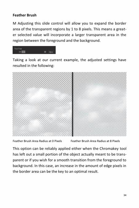
Feather Brush
M Adjusting this slide control will allow you to expand the border
area of the transparent regions by 1 to 8 pixels. This means a great-
er selected value will incorporate a larger transparent area in the
region between the foreground and the background.
Taking a look at our current example, the adjusted settings have
resulted in the following:
Feather Brush Area Radius at 0 Pixels Feather Brush Area Radius at 8 Pixels
This option can be reliably applied either when the Chromakey tool
has left out a small portion of the object actually meant to be trans-
parent or if you wish for a smooth transition from the foreground to
background. In this case, an increase in the amount of edge pixels in
the border area can be the key to an optimal result.
35
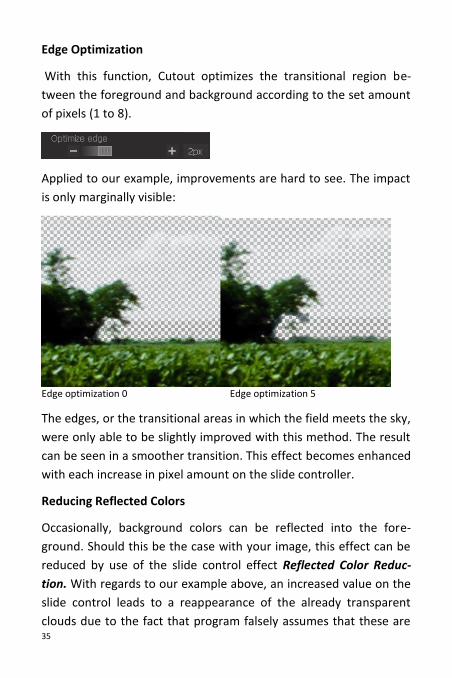
Edge Optimization
With this function, Cutout optimizes the transitional region be-
tween the foreground and background according to the set amount
of pixels (1 to 8).
Applied to our example, improvements are hard to see. The impact
is only marginally visible:
Edge optimization 0 Edge optimization 5
The edges, or the transitional areas in which the field meets the sky,
were only able to be slightly improved with this method. The result
can be seen in a smoother transition. This effect becomes enhanced
with each increase in pixel amount on the slide controller.
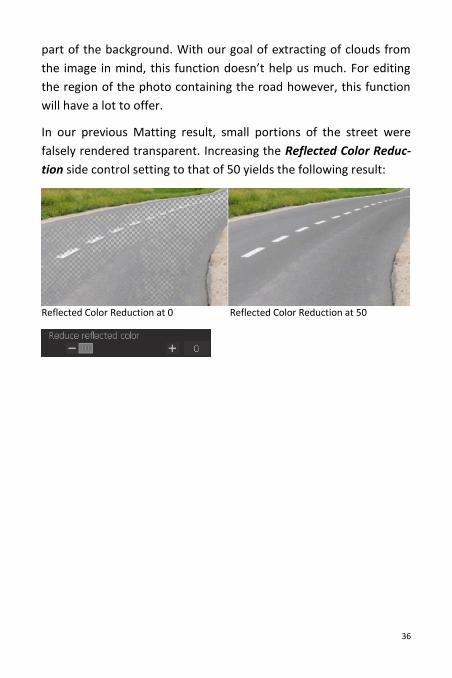
Reducing Reflected Colors
Occasionally, background colors can be reflected into the fore-
ground. Should this be the case with your image, this effect can be
reduced by use of the slide control effect Reflected Color Reduc-
tion. With regards to our example above, an increased value on the
slide control leads to a reappearance of the already transparent
clouds due to the fact that program falsely assumes that these are
36
part of the background. With our goal of extracting of clouds from
the image in mind, this function doesn’t help us much. For editing
the region of the photo containing the road however, this function
will have a lot to offer.
In our previous Matting result, small portions of the street were
falsely rendered transparent. Increasing the Reflected Color Reduc-
tion side control setting to that of 50 yields the following result:
Reflected Color Reduction at 0 Reflected Color Reduction at 50
37
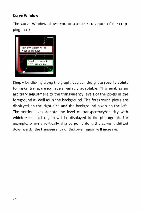
Curve Window
The Curve Window allows you to alter the curvature of the crop-
ping-mask.
Simply by clicking along the graph, you can designate specific points
to make transparency levels variably adaptable. This enables an
arbitrary adjustment to the transparency levels of the pixels in the
foreground as well as in the background. The foreground pixels are
displayed on the right side and the background pixels on the left.
The vertical axes denote the level of transparency/opacity with
which each pixel region will be displayed in the photograph. For
example, when a vertically aligned point along the curve is shifted
downwards, the transparency of this pixel region will increase.
38
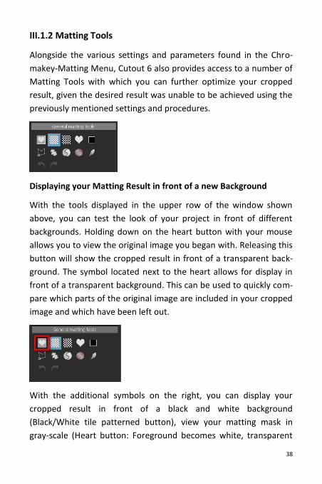
III.1.2 Matting Tools
Alongside the various settings and parameters found in the Chro-
makey-Matting Menu, Cutout 6 also provides access to a number of
Matting Tools with which you can further optimize your cropped
result, given the desired result was unable to be achieved using the
previously mentioned settings and procedures.
Displaying your Matting Result in front of a new Background
With the tools displayed in the upper row of the window shown
above, you can test the look of your project in front of different
backgrounds. Holding down on the heart button with your mouse
allows you to view the original image you began with. Releasing this
button will show the cropped result in front of a transparent back-
ground. The symbol located next to the heart allows for display in
front of a transparent background. This can be used to quickly com-
pare which parts of the original image are included in your cropped
image and which have been left out.
With the additional symbols on the right, you can display your
cropped result in front of a black and white background
(Black/White tile patterned button), view your matting mask in
gray-scale (Heart button: Foreground becomes white, transparent
39
region black and partially transparent pixels turn gray) or simply
place your cropped result in front of a single-colored background
(colored square).
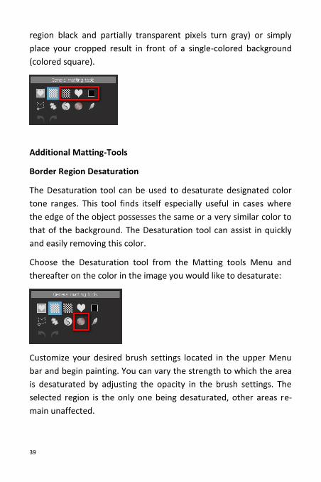
Additional Matting-Tools
Border Region Desaturation
The Desaturation tool can be used to desaturate designated color
tone ranges. This tool finds itself especially useful in cases where
the edge of the object possesses the same or a very similar color to
that of the background. The Desaturation tool can assist in quickly
and easily removing this color.
Choose the Desaturation tool from the Matting tools Menu and
thereafter on the color in the image you would like to desaturate:
Customize your desired brush settings located in the upper Menu
bar and begin painting. You can vary the strength to which the area
is desaturated by adjusting the opacity in the brush settings. The
selected region is the only one being desaturated, other areas re-
main unaffected.
40
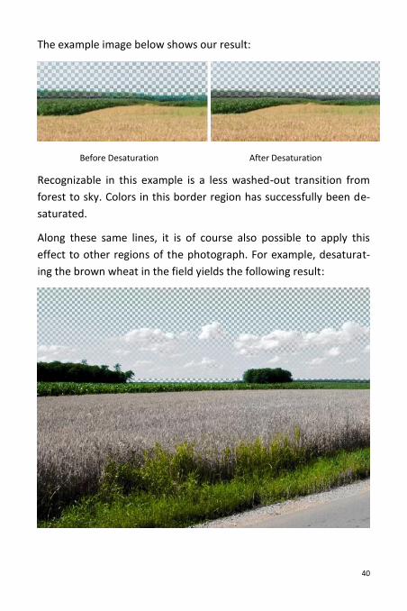
The example image below shows our result:
Before Desaturation After Desaturation
Recognizable in this example is a less washed-out transition from
forest to sky. Colors in this border region has successfully been de-
saturated.
Along these same lines, it is of course also possible to apply this
effect to other regions of the photograph. For example, desaturat-
ing the brown wheat in the field yields the following result:
41
Feather Brush
The Feather Brush allows for the softening of specific regions and a
therefore noticeably smoother transition. Quite often the effects
only become visible when the image is zoomed in on. Adjust the
brush settings and simply paint over regions where a softer transi-
tion is desired.
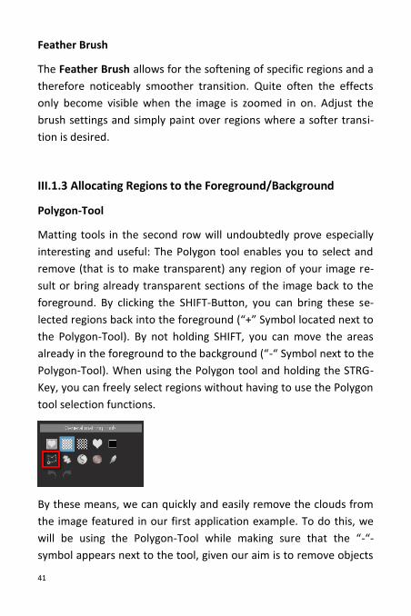
III.1.3 Allocating Regions to the Foreground/Background
Polygon-Tool
Matting tools in the second row will undoubtedly prove especially
interesting and useful: The Polygon tool enables you to select and
remove (that is to make transparent) any region of your image re-
sult or bring already transparent sections of the image back to the
foreground. By clicking the SHIFT-Button, you can bring these se-
lected regions back into the foreground (“+” Symbol located next to
the Polygon-Tool). By not holding SHIFT, you can move the areas
already in the foreground to the background (“-“ Symbol next to the
Polygon-Tool). When using the Polygon tool and holding the STRG-
Key, you can freely select regions without having to use the Polygon
tool selection functions.
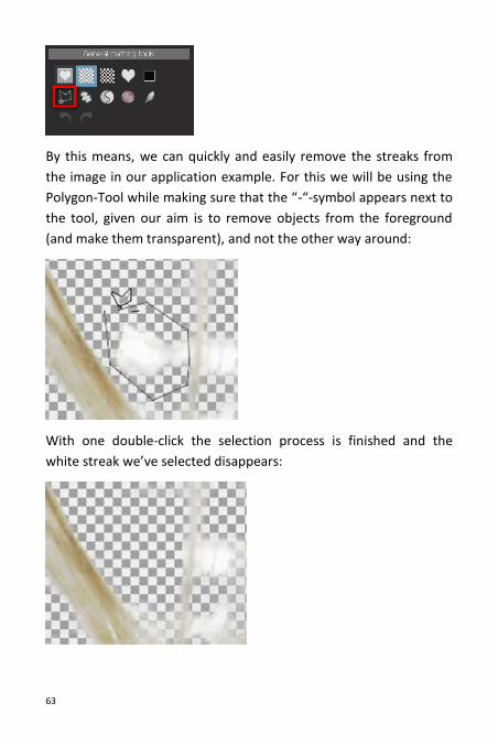
By these means, we can quickly and easily remove the clouds from
the image featured in our first application example. To do this, we
will be using the Polygon-Tool while making sure that the “-“-
symbol appears next to the tool, given our aim is to remove objects
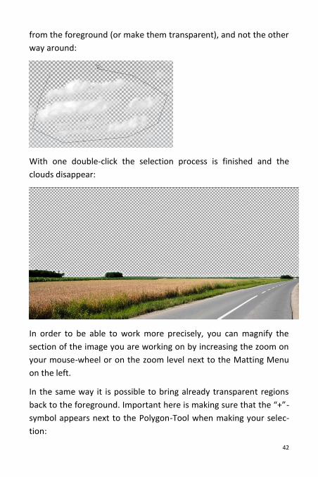
42
from the foreground (or make them transparent), and not the other
way around:
With one double-click the selection process is finished and the
clouds disappear:
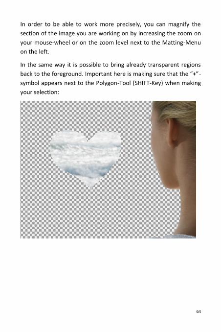
In order to be able to work more precisely, you can magnify the
section of the image you are working on by increasing the zoom on
your mouse-wheel or on the zoom level next to the Matting Menu
on the left.
In the same way it is possible to bring already transparent regions
back to the foreground. Important here is making sure that the “+”-
symbol appears next to the Polygon-Tool when making your selec-
tion:
43
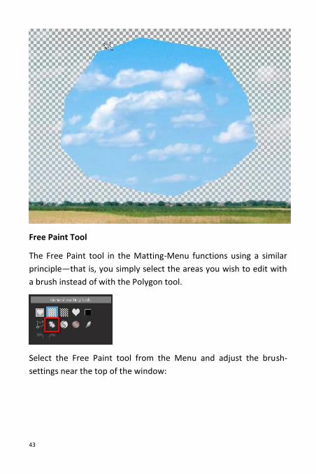
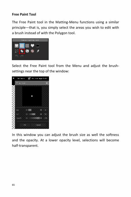
Free Paint Tool
The Free Paint tool in the Matting-Menu functions using a similar
principle—that is, you simply select the areas you wish to edit with
a brush instead of with the Polygon tool.
Select the Free Paint tool from the Menu and adjust the brush-
settings near the top of the window:
44
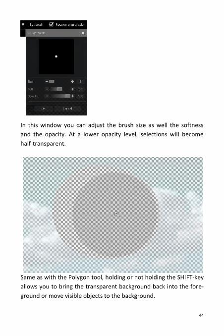
In this window you can adjust the brush size as well the softness
and the opacity. At a lower opacity level, selections will become
half-transparent.
Same as with the Polygon tool, holding or not holding the SHIFT-key
allows you to bring the transparent background back into the fore-
ground or move visible objects to the background.
45
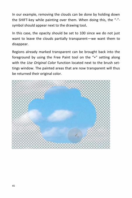
In our example, removing the clouds can be done by holding down
the SHIFT-key while painting over them. When doing this, the “-”-
symbol should appear next to the drawing tool.
In this case, the opacity should be set to 100 since we do not just
want to leave the clouds partially transparent—we want them to
disappear.
Regions already marked transparent can be brought back into the
foreground by using the Free Paint tool on the “+” setting along
with the Use Original Color function located next to the brush set-
tings window. The painted areas that are now transparent will thus
be returned their original color.
46
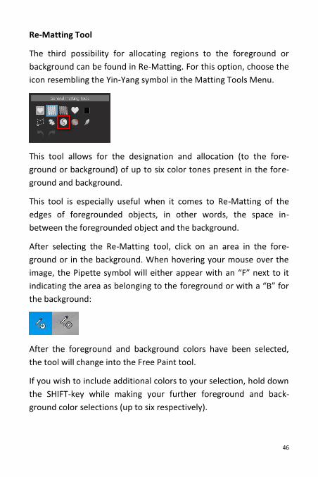
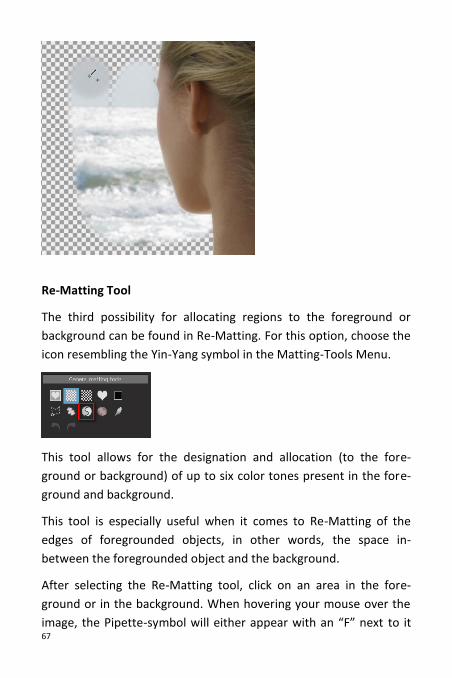
Re-Matting Tool
The third possibility for allocating regions to the foreground or
background can be found in Re-Matting. For this option, choose the
icon resembling the Yin-Yang symbol in the Matting Tools Menu.
This tool allows for the designation and allocation (to the fore-
ground or background) of up to six color tones present in the fore-
ground and background.
This tool is especially useful when it comes to Re-Matting of the
edges of foregrounded objects, in other words, the space in-
between the foregrounded object and the background.
After selecting the Re-Matting tool, click on an area in the fore-
ground or in the background. When hovering your mouse over the
image, the Pipette symbol will either appear with an “F” next to it
indicating the area as belonging to the foreground or with a “B” for
the background:
After the foreground and background colors have been selected,
the tool will change into the Free Paint tool.
If you wish to include additional colors to your selection, hold down
the SHIFT-key while making your further foreground and back-
ground color selections (up to six respectively).
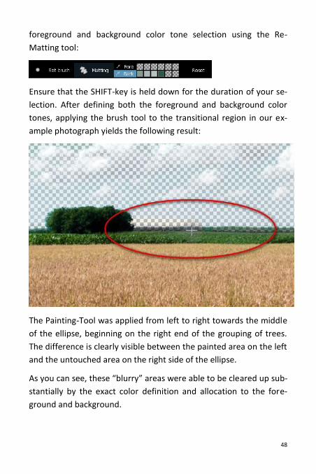
47
When transferring to the painting stage, the brush settings (Size,
Softness and Opacity) can be adjusted accordingly and the Re-
Matting process may begin:
When using the Free Paint tool to paint your image, only the color
tones you previously designated as foreground colors will remain,
the rest will become transparent. Color tones designated as belong-
ing to the background will remain transparent in the same way,
leaving visible those colors having not made it into the background
selection. This method can help to optimize the appearance of ele-
ments in the transitional regions—that is when working in spaces
between the foregrounded object and the background. With one
right-click of the mouse you can reset your previous color tone se-
lection.
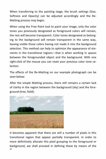
The effects of the Re-Matting on our example photograph can be
seen below:
After the simple Matting process, there still remains a certain lack
of clarity in the region between the background (sky) and the fore-
ground (tree, field):
It becomes apparent that there are still a number of pixels in this
transitional region that appear partially transparent. In order to
more definitively allocate this pixel grouping to the foreground or
background, we shall proceed in defining these by means of the
48
foreground and background color tone selection using the Re-
Matting tool:
Ensure that the SHIFT-key is held down for the duration of your se-
lection. After defining both the foreground and background color
tones, applying the brush tool to the transitional region in our ex-
ample photograph yields the following result:
The Painting-Tool was applied from left to right towards the middle
of the ellipse, beginning on the right end of the grouping of trees.
The difference is clearly visible between the painted area on the left
and the untouched area on the right side of the ellipse.
As you can see, these “blurry” areas were able to be cleared up sub-
stantially by the exact color definition and allocation to the fore-
ground and background.
49
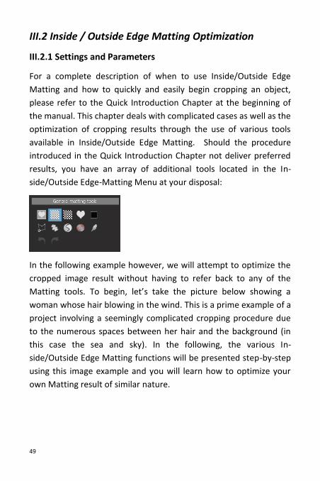
III.2 Inside / Outside Edge Matting Optimization
III.2.1 Settings and Parameters
For a complete description of when to use Inside/Outside Edge
Matting and how to quickly and easily begin cropping an object,
please refer to the Quick Introduction Chapter at the beginning of
the manual. This chapter deals with complicated cases as well as the
optimization of cropping results through the use of various tools
available in Inside/Outside Edge Matting. Should the procedure
introduced in the Quick Introduction Chapter not deliver preferred
results, you have an array of additional tools located in the In-
side/Outside Edge-Matting Menu at your disposal:
In the following example however, we will attempt to optimize the
cropped image result without having to refer back to any of the
Matting tools. To begin, let’s take the picture below showing a
woman whose hair blowing in the wind. This is a prime example of a
project involving a seemingly complicated cropping procedure due
to the numerous spaces between her hair and the background (in
this case the sea and sky). In the following, the various In-
side/Outside Edge Matting functions will be presented step-by-step
using this image example and you will learn how to optimize your
own Matting result of similar nature.
50
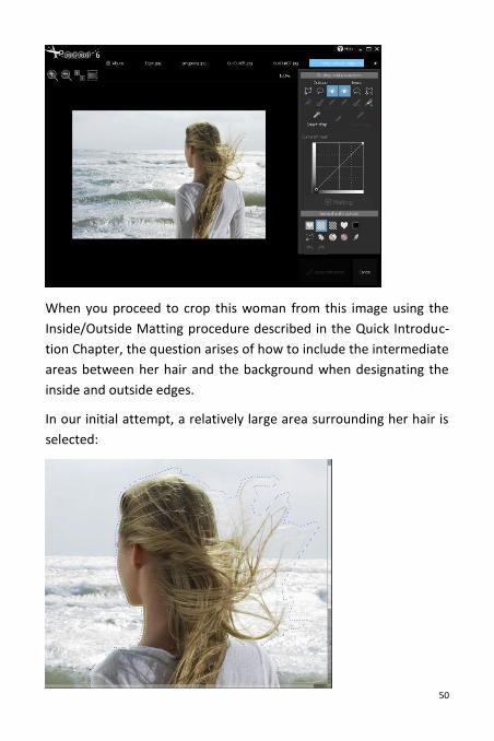
When you proceed to crop this woman from this image using the
Inside/Outside Matting procedure described in the Quick Introduc-
tion Chapter, the question arises of how to include the intermediate
areas between her hair and the background when designating the
inside and outside edges.
In our initial attempt, a relatively large area surrounding her hair is
selected:
51
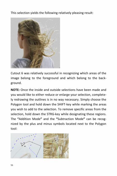
This selection yields the following relatively pleasing result:
Cutout 6 was relatively successful in recognizing which areas of the
image belong to the foreground and which belong to the back-
ground.
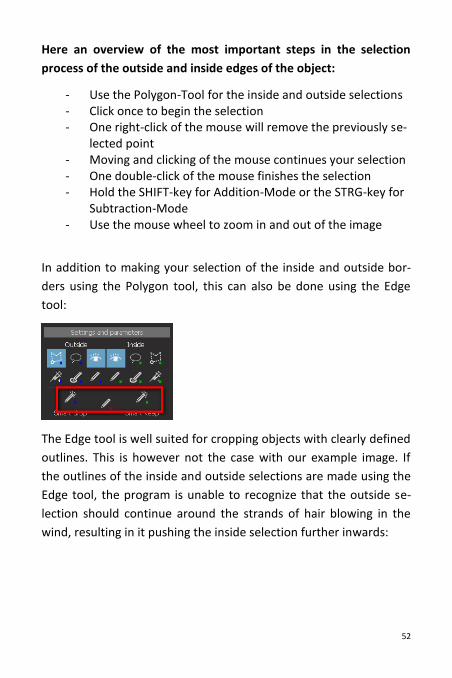
NOTE: Once the inside and outside selections have been made and
you would like to either reduce or enlarge your selection, complete-
ly redrawing the outlines is in no way necessary. Simply choose the
Polygon tool and hold down the SHIFT-key while marking the areas
you wish to add to the selection. To remove specific areas from the
selection, hold down the STRG-key while designating these regions.
The “Addition Mode” and the “Subtraction Mode” can be recog-
nized by the plus and minus symbols located next to the Polygon
tool:
52
Here an overview of the most important steps in the selection
process of the outside and inside edges of the object:
- Use the Polygon-Tool for the inside and outside selections - Click once to begin the selection - One right-click of the mouse will remove the previously se-
lected point - Moving and clicking of the mouse continues your selection - One double-click of the mouse finishes the selection - Hold the SHIFT-key for Addition-Mode or the STRG-key for
Subtraction-Mode - Use the mouse wheel to zoom in and out of the image
In addition to making your selection of the inside and outside bor-
ders using the Polygon tool, this can also be done using the Edge
tool:
The Edge tool is well suited for cropping objects with clearly defined
outlines. This is however not the case with our example image. If
the outlines of the inside and outside selections are made using the
Edge tool, the program is unable to recognize that the outside se-
lection should continue around the strands of hair blowing in the
wind, resulting in it pushing the inside selection further inwards:
53
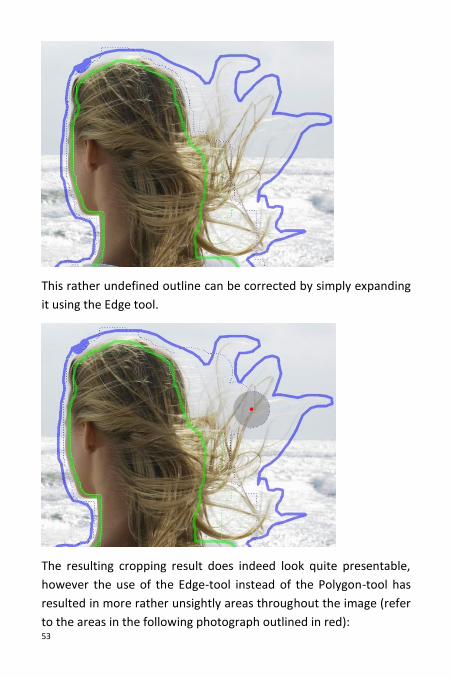
This rather undefined outline can be corrected by simply expanding
it using the Edge tool.
The resulting cropping result does indeed look quite presentable,
however the use of the Edge-tool instead of the Polygon-tool has
resulted in more rather unsightly areas throughout the image (refer
to the areas in the following photograph outlined in red):
54
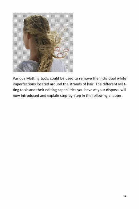
Various Matting tools could be used to remove the individual white
imperfections located around the strands of hair. The different Mat-
ting tools and their editing capabilities you have at your disposal will
now introduced and explain step-by-step in the following chapter.
55
III.2.2 Cropping Intermediate Areas of an Object using the
Edge Tool
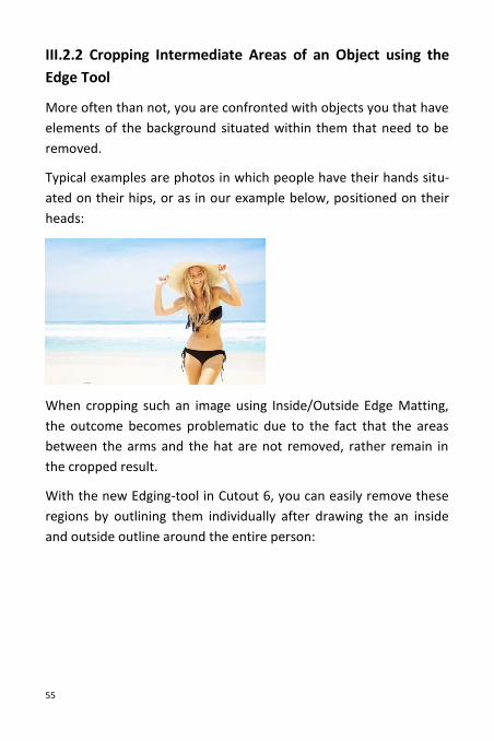
More often than not, you are confronted with objects you that have
elements of the background situated within them that need to be
removed.
Typical examples are photos in which people have their hands situ-
ated on their hips, or as in our example below, positioned on their
heads:
When cropping such an image using Inside/Outside Edge Matting,
the outcome becomes problematic due to the fact that the areas
between the arms and the hat are not removed, rather remain in
the cropped result.
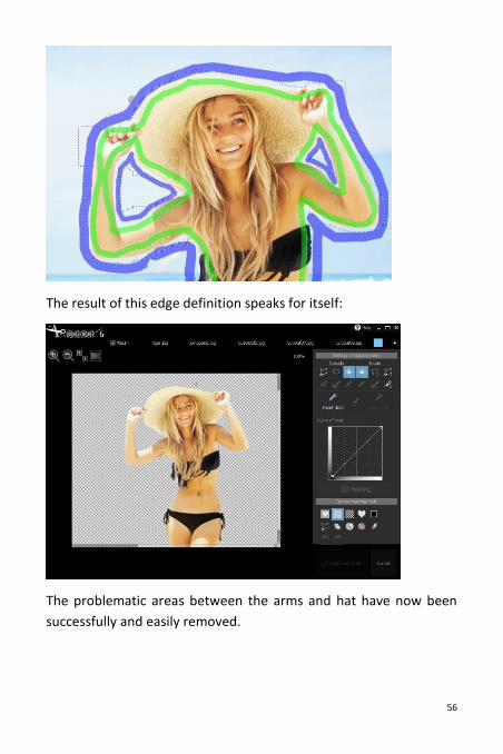
With the new Edging-tool in Cutout 6, you can easily remove these
regions by outlining them individually after drawing the an inside
and outside outline around the entire person:
56
The result of this edge definition speaks for itself:
The problematic areas between the arms and hat have now been
successfully and easily removed.
57
III.2.3 Syringe Tool for Detail Enhancement
The Syringe-tool, located directly next to the Polygon tool in the
Menu, enables you to add individual pixels to both the inside and
outside object edge selections.
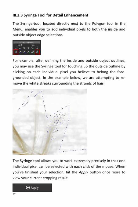
For example, after defining the inside and outside object outlines,
you may use the Syringe tool for touching up the outside outline by
clicking on each individual pixel you believe to belong the fore-
grounded object. In the example below, we are attempting to re-
move the white streaks surrounding the strands of hair:
The Syringe-tool allows you to work extremely precisely in that one
individual pixel can be selected with each click of the mouse. When
you’ve finished your selection, hit the Apply button once more to
view your current cropping result.
58
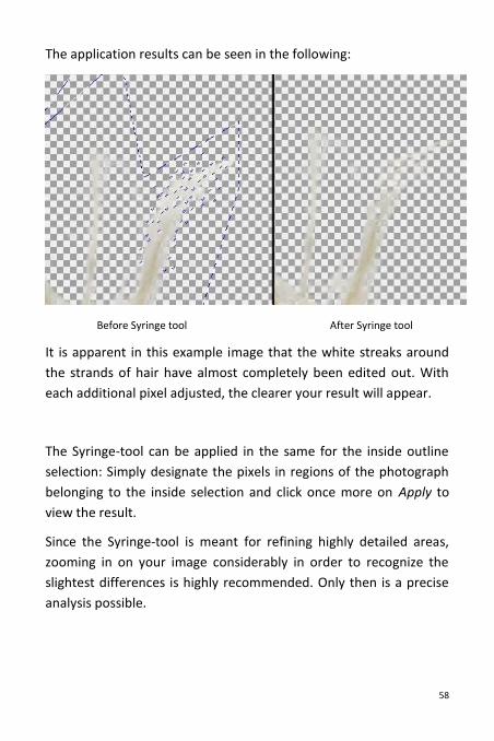
The application results can be seen in the following:
Before Syringe tool After Syringe tool
It is apparent in this example image that the white streaks around
the strands of hair have almost completely been edited out. With
each additional pixel adjusted, the clearer your result will appear.
The Syringe-tool can be applied in the same for the inside outline
selection: Simply designate the pixels in regions of the photograph
belonging to the inside selection and click once more on Apply to
view the result.
Since the Syringe-tool is meant for refining highly detailed areas,
zooming in on your image considerably in order to recognize the
slightest differences is highly recommended. Only then is a precise
analysis possible.
59
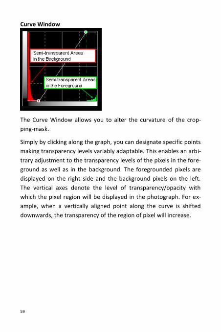
Curve Window
The Curve Window allows you to alter the curvature of the crop-
ping-mask.
Simply by clicking along the graph, you can designate specific points
making transparency levels variably adaptable. This enables an arbi-
trary adjustment to the transparency levels of the pixels in the fore-
ground as well as in the background. The foregrounded pixels are
displayed on the right side and the background pixels on the left.
The vertical axes denote the level of transparency/opacity with
which the pixel region will be displayed in the photograph. For ex-
ample, when a vertically aligned point along the curve is shifted
downwards, the transparency of the region of pixel will increase.
60
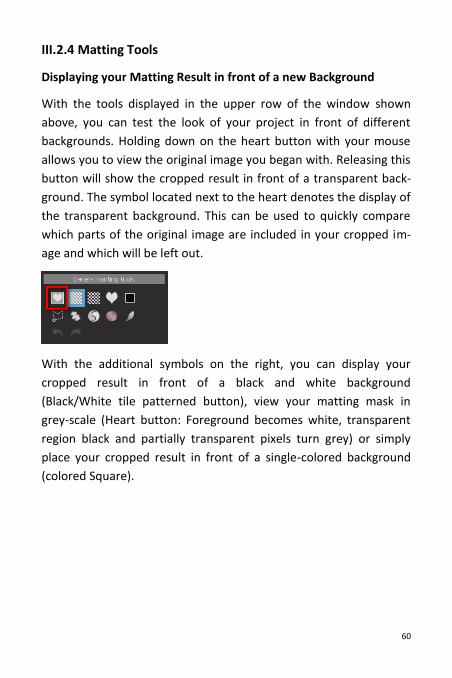
III.2.4 Matting Tools
Displaying your Matting Result in front of a new Background
With the tools displayed in the upper row of the window shown
above, you can test the look of your project in front of different
backgrounds. Holding down on the heart button with your mouse
allows you to view the original image you began with. Releasing this
button will show the cropped result in front of a transparent back-
ground. The symbol located next to the heart denotes the display of
the transparent background. This can be used to quickly compare
which parts of the original image are included in your cropped im-
age and which will be left out.
With the additional symbols on the right, you can display your
cropped result in front of a black and white background
(Black/White tile patterned button), view your matting mask in
grey-scale (Heart button: Foreground becomes white, transparent
region black and partially transparent pixels turn grey) or simply
place your cropped result in front of a single-colored background
(colored Square).
61
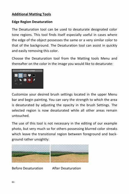
Additional Matting Tools
Edge Region Desaturation
The Desaturation tool can be used to desaturate designated color
tone regions. This tool finds itself especially useful in cases where
the edge of the object possesses the same or a very similar color to
that of the background. The Desaturation tool can assist in quickly
and easily removing this color.
Choose the Desaturation tool from the Matting tools Menu and
thereafter on the color in the image you would like to desaturate:
Customize your desired brush settings located in the upper Menu
bar and begin painting. You can vary the strength to which the area
is desaturated by adjusting the opacity in the brush Settings. The
selected region is now desaturated while all other areas remain
untouched.
The use of this tool is not necessary in the editing of our example
photo, but very much so for others possessing blurred color streaks
which leave the transitional region between foreground and back-
ground rather unsightly:
Before Desaturation After Desaturation
62
It can be seen in the images above that painting over the transition-
al region between the field and the sky has resulted in the success-
ful allocation of undefined, half transparent pixels to the back-
ground and have thus been rendered transparent.
Feather Brush
The Feather Brush allows the softening of specific regions and
therefore for a noticeably smoother transition. Quite often the ef-
fects only become visible when the picture is magnified to a high
degree. Adjust the Brush-Settings and simply paint over regions
where a softer transition is desired.
III.2.5 Allocating Regions to the Foreground/Background
Polygon Tool
Matting tools in the second row will undoubtedly prove especially
interesting and useful: The Polygon tool enables you to select and
remove (that is to make transparent) any region of your image re-
sult or bring already transparent sections of the image back to the
foreground. By clicking the SHIFT-Button, you can bring these se-
lected regions back into the foreground (“+” Symbol located next to
the Polygon-Tool). By not holding SHIFT, you can move the areas
already in the foreground to the background (“-“ Symbol next to the
Polygon-Tool). When using the Polygon tool and holding the STRG-
Key, you can freely select regions without having to use the Polygon
tool selection functions.
63
By this means, we can quickly and easily remove the streaks from
the image in our application example. For this we will be using the
Polygon-Tool while making sure that the “-“-symbol appears next to
the tool, given our aim is to remove objects from the foreground
(and make them transparent), and not the other way around:
With one double-click the selection process is finished and the
white streak we’ve selected disappears:
64
In order to be able to work more precisely, you can magnify the
section of the image you are working on by increasing the zoom on
your mouse-wheel or on the zoom level next to the Matting-Menu
on the left.
In the same way it is possible to bring already transparent regions
back to the foreground. Important here is making sure that the “+”-
symbol appears next to the Polygon-Tool (SHIFT-Key) when making
your selection:
65
Free Paint Tool
The Free Paint tool in the Matting-Menu functions using a similar
principle—that is, you simply select the areas you wish to edit with
a brush instead of with the Polygon tool.
Select the Free Paint tool from the Menu and adjust the brush-
settings near the top of the window:
In this window you can adjust the brush size as well the softness
and the opacity. At a lower opacity level, selections will become
half-transparent.
66
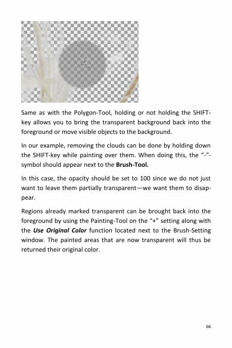
Same as with the Polygon-Tool, holding or not holding the SHIFT-
key allows you to bring the transparent background back into the
foreground or move visible objects to the background.
In our example, removing the clouds can be done by holding down
the SHIFT-key while painting over them. When doing this, the “-”-
symbol should appear next to the Brush-Tool.
In this case, the opacity should be set to 100 since we do not just
want to leave them partially transparent—we want them to disap-
pear.
Regions already marked transparent can be brought back into the
foreground by using the Painting-Tool on the “+” setting along with
the Use Original Color function located next to the Brush-Setting
window. The painted areas that are now transparent will thus be
returned their original color.
67
Re-Matting Tool
The third possibility for allocating regions to the foreground or
background can be found in Re-Matting. For this option, choose the
icon resembling the Yin-Yang symbol in the Matting-Tools Menu.
This tool allows for the designation and allocation (to the fore-
ground or background) of up to six color tones present in the fore-
ground and background.
This tool is especially useful when it comes to Re-Matting of the
edges of foregrounded objects, in other words, the space in-
between the foregrounded object and the background.
After selecting the Re-Matting tool, click on an area in the fore-
ground or in the background. When hovering your mouse over the
image, the Pipette-symbol will either appear with an “F” next to it
68
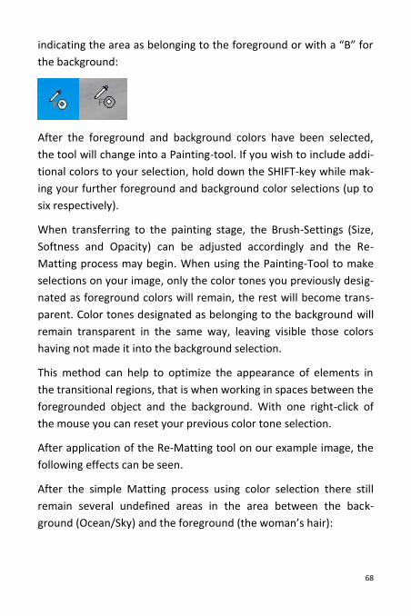
indicating the area as belonging to the foreground or with a “B” for
the background:
After the foreground and background colors have been selected,
the tool will change into a Painting-tool. If you wish to include addi-
tional colors to your selection, hold down the SHIFT-key while mak-
ing your further foreground and background color selections (up to
six respectively).
When transferring to the painting stage, the Brush-Settings (Size,
Softness and Opacity) can be adjusted accordingly and the Re-
Matting process may begin. When using the Painting-Tool to make
selections on your image, only the color tones you previously desig-
nated as foreground colors will remain, the rest will become trans-
parent. Color tones designated as belonging to the background will
remain transparent in the same way, leaving visible those colors
having not made it into the background selection.
This method can help to optimize the appearance of elements in
the transitional regions, that is when working in spaces between the
foregrounded object and the background. With one right-click of
the mouse you can reset your previous color tone selection.
After application of the Re-Matting tool on our example image, the
following effects can be seen.
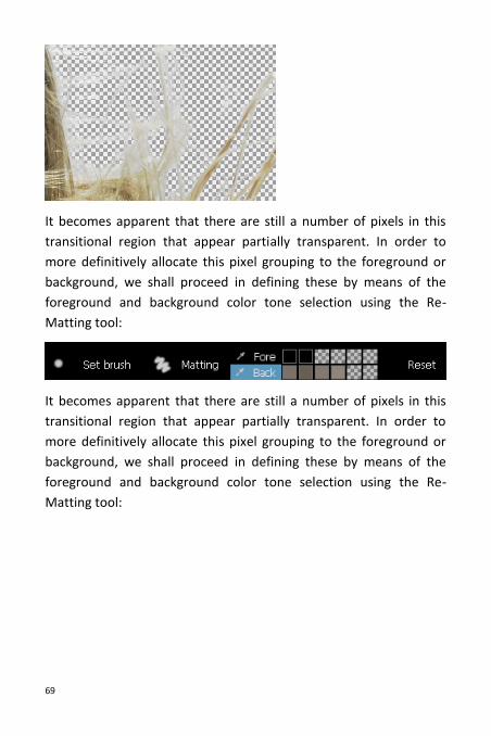
After the simple Matting process using color selection there still
remain several undefined areas in the area between the back-
ground (Ocean/Sky) and the foreground (the woman’s hair):
69
It becomes apparent that there are still a number of pixels in this
transitional region that appear partially transparent. In order to
more definitively allocate this pixel grouping to the foreground or
background, we shall proceed in defining these by means of the
foreground and background color tone selection using the Re-
Matting tool:
70
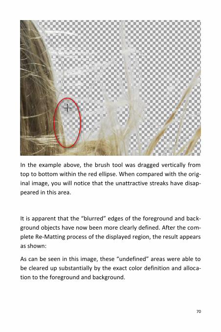
In the example above, the brush tool was dragged vertically from
top to bottom within the red ellipse. When compared with the orig-
inal image, you will notice that the unattractive streaks have disap-
peared in this area.
It is apparent that the “blurred” edges of the foreground and back-
ground objects have now been more clearly defined. After the com-
plete Re-Matting process of the displayed region, the result appears
as shown:
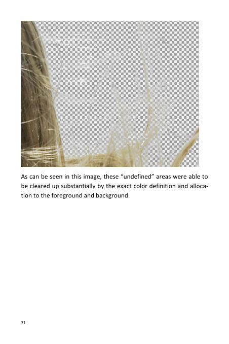
As can be seen in this image, these “undefined” areas were able to
be cleared up substantially by the exact color definition and alloca-
tion to the foreground and background.
71
As can be seen in this image, these “undefined” areas were able to
be cleared up substantially by the exact color definition and alloca-
tion to the foreground and background.
72
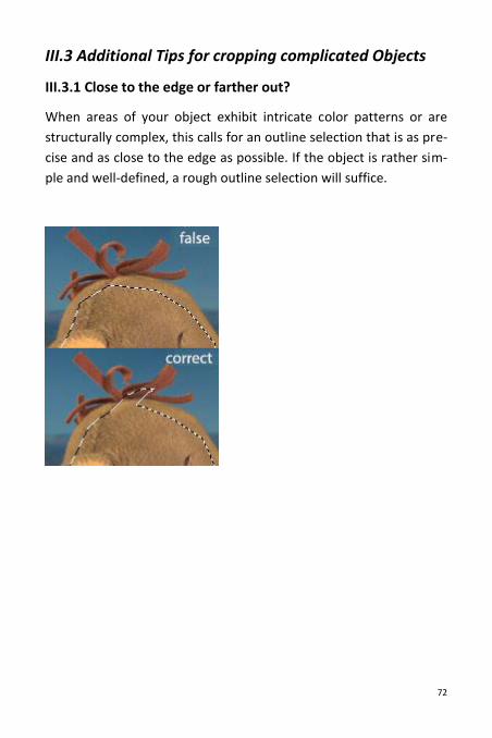
III.3 Additional Tips for cropping complicated Objects
III.3.1 Close to the edge or farther out?
When areas of your object exhibit intricate color patterns or are
structurally complex, this calls for an outline selection that is as pre-
cise and as close to the edge as possible. If the object is rather sim-
ple and well-defined, a rough outline selection will suffice.
73
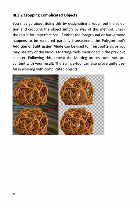
III.3.2 Cropping Complicated Objects
You may go about doing this by designating a rough outline selec-
tion and cropping the object simply by way of this method. Check
the result for imperfections. If either the foreground or background
happens to be rendered partially transparent, the Polygon-tool’s
Addition or Subtraction Mode can be used to insert patterns or you
may use any of the various Matting-tools mentioned in the previous
chapter. Following this, repeat the Matting process until you are
content with your result. The Syringe-tool can also prove quite use-
ful in working with complicated objects.
74
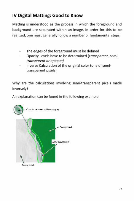
IV Digital Matting: Good to Know
Matting is understood as the process in which the foreground and
background are separated within an image. In order for this to be
realized, one must generally follow a number of fundamental steps.
- The edges of the foreground must be defined - Opacity Levels have to be determined (transparent, semi-
transparent or opaque) - Inverse Calculation of the original color tone of semi-
transparent pixels
Why are the calculations involving semi-transparent pixels made
inversely?
An explanation can be found in the following example:
75
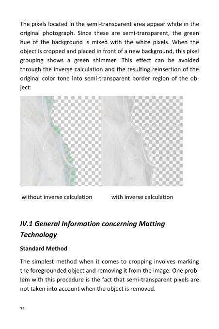
The pixels located in the semi-transparent area appear white in the
original photograph. Since these are semi-transparent, the green
hue of the background is mixed with the white pixels. When the
object is cropped and placed in front of a new background, this pixel
grouping shows a green shimmer. This effect can be avoided
through the inverse calculation and the resulting reinsertion of the
original color tone into semi-transparent border region of the ob-
ject:
without inverse calculation with inverse calculation
IV.1 General Information concerning Matting
Technology
Standard Method
The simplest method when it comes to cropping involves marking
the foregrounded object and removing it from the image. One prob-
lem with this procedure is the fact that semi-transparent pixels are
not taken into account when the object is removed.
76
Advanced Tools
Advanced Tools such as the magnetic lasso are also available for
use, however the same problem arises as in the standard outline
selection method, that is that semi-transparent pixels are not in-
cluded in the cropping procedure.
IV.2 Chromakey Matting
This procedure finds its origins in the video-editing sector and was
used to crop objects situated primarily in front of green or blue
backdrop while being filmed or photographed. All pixels possessing
a color other than that of the background were allocated to the
foreground.
When using this method, it is assumed however that objects in the
foreground are not transparent. For example, photographing a
translucent article of clothing against a chroma key background
would result in the object appearing to have a blue or green tint,
this also when placed in front of a new background. This aspect of
the chroma key process yields a seemingly unnatural outcome and
can be easily compared with stunt scenes from early action movies
shot using green-screen.
This method tends to be very useful, however it has two require-
ments:
- The background color cannot be present in the foreground. If it does happen to appear in the foreground, it will be al-
77
located to the background and therefore be rendered transparent or semi-transparent.
- The background must be uniform in color. Differences in the background color will not be accounted for and will thus be added to the background selection.
Chroma Key technologies are for this reason used predominantly in
professional environments.
IV.3 Inside/Outside Edge Matting
With regards to the previously mentioned limitations attached to
the Chroma Key Matting process, an alternative Matting method is
required. This new method should have no limitations on back-
ground color, be able to support semi-transparency and simple to
use.
The procedure “Inside/Outside Edge Matting” fulfills these criteria
and serves as an appropriate solution for the majority of photo-
editing projects.
This method of cropping incorporates the definition of the inside
and outside edges of an object. The selection of an inside outline is
made by marking an area inside the object that is to be cropped.
When making this selection, it is important to make your selection
as close to the inside edge as possible. Following this step is the
selection of the outside outline which is to be drawn as close to the
outside edge as possible. The space in-between these two selec-
tions is the semi-transparent region.
Due to the fact that the program is never able to exactly identify the
individual color values, the first stage of editing can tend to contain
errors.
78
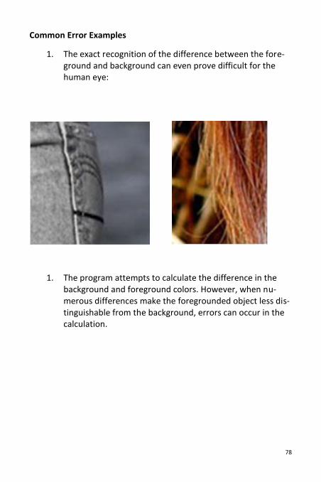
Common Error Examples
1. The exact recognition of the difference between the fore-ground and background can even prove difficult for the human eye:
1. The program attempts to calculate the difference in the background and foreground colors. However, when nu-merous differences make the foregrounded object less dis-tinguishable from the background, errors can occur in the calculation.
79
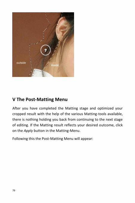
V The Post-Matting Menu
After you have completed the Matting stage and optimized your
cropped result with the help of the various Matting-tools available,
there is nothing holding you back from continuing to the next stage
of editing. If the Matting result reflects your desired outcome, click
on the Apply button in the Matting-Menu.
Following this the Post-Matting Menu will appear:
80
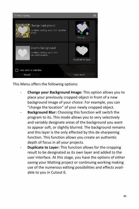
This Menu offers the following options:
- Change your Background Image: This option allows you to place your previously cropped object in front of a new background image of your choice. For example, you can “change the location” of your newly cropped object.
- Background Blur: Choosing this function will switch the program to its. This mode allows you to very selectively and variably designate areas of the background you want to appear soft, or slightly blurred. The background remains and this layer is the only effected by this de-sharpening function. This function allows you create an authentic depth of focus in all your projects.
- Duplicate to Layer: This function allows for the cropping result to be designated as its own layer and added to the user interface. At this stage, you have the options of either saving your Matting project or continuing working making use of the numerous editing possibilities and effects avail-able to you in Cutout 6.
81
- Layer Separation: This function can only be activated when working with a base layer and saves both the foreground and background as their own layers.
- Delete Layers: This option is only available for use when working with layers other than the basis layer. The back-ground is deleted and only the cropped object will remain as its own layer.
In addition to these options, choosing the option Save Result will
allow you to save your Matting result to any location of your choice
in either .png or .psd format.
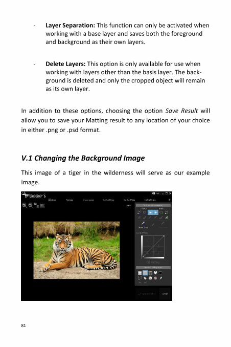
V.1 Changing the Background Image
This image of a tiger in the wilderness will serve as our example
image.
82
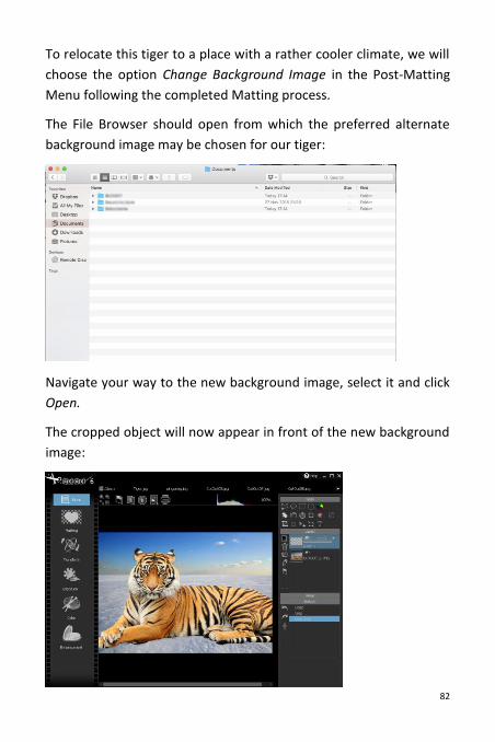
To relocate this tiger to a place with a rather cooler climate, we will
choose the option Change Background Image in the Post-Matting
Menu following the completed Matting process.
The File Browser should open from which the preferred alternate
background image may be chosen for our tiger:
Navigate your way to the new background image, select it and click
Open.
The cropped object will now appear in front of the new background
image:
83
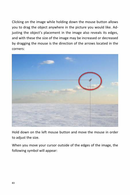
Clicking on the image while holding down the mouse button allows
you to drag the object anywhere in the picture you would like. Ad-
justing the object’s placement in the image also reveals its edges,
and with these the size of the image may be increased or decreased
by dragging the mouse is the direction of the arrows located in the
corners:
Hold down on the left mouse button and move the mouse in order
to adjust the size.
When you move your cursor outside of the edges of the image, the
following symbol will appear:
84
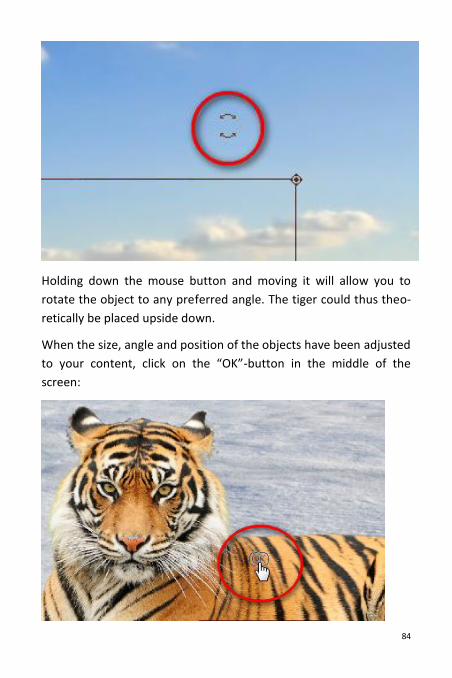
Holding down the mouse button and moving it will allow you to
rotate the object to any preferred angle. The tiger could thus theo-
retically be placed upside down.
When the size, angle and position of the objects have been adjusted
to your content, click on the “OK”-button in the middle of the
screen:
85
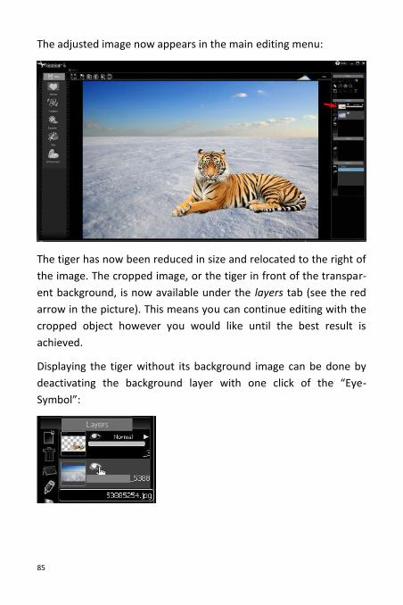
The adjusted image now appears in the main editing menu:
The tiger has now been reduced in size and relocated to the right of
the image. The cropped image, or the tiger in front of the transpar-
ent background, is now available under the layers tab (see the red
arrow in the picture). This means you can continue editing with the
cropped object however you would like until the best result is
achieved.
Displaying the tiger without its background image can be done by
deactivating the background layer with one click of the “Eye-
Symbol”:
86
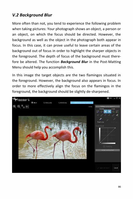
V.2 Background Blur
More often than not, you tend to experience the following problem
when taking pictures: Your photograph shows an object, a person or
an object, on which the focus should be directed. However, the
background as well as the object in the photograph both appear in
focus. In this case, it can prove useful to leave certain areas of the
background out of focus in order to highlight the sharper objects in
the foreground. The depth of focus of the background must there-
fore be altered. The function Background Blur in the Post-Matting
Menu should help you accomplish this.
In this image the target objects are the two flamingos situated in
the foreground. However, the background also appears in focus. In
order to more effectively align the focus on the flamingos in the
foreground, the background should be slightly de-sharpened.
87
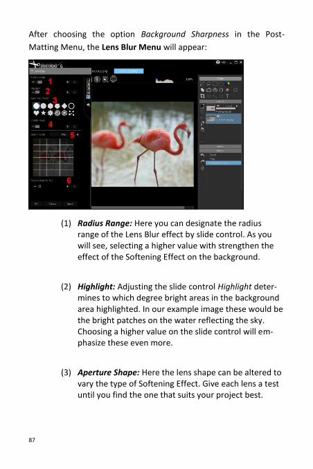
After choosing the option Background Sharpness in the Post-
Matting Menu, the Lens Blur Menu will appear:
(1) Radius Range: Here you can designate the radius range of the Lens Blur effect by slide control. As you will see, selecting a higher value with strengthen the effect of the Softening Effect on the background.
(2) Highlight: Adjusting the slide control Highlight deter-mines to which degree bright areas in the background area highlighted. In our example image these would be the bright patches on the water reflecting the sky. Choosing a higher value on the slide control will em-phasize these even more.
(3) Aperture Shape: Here the lens shape can be altered to vary the type of Softening Effect. Give each lens a test until you find the one that suits your project best.
88
(4) Mask Rotation: This function allows you to change the direction of the Soft Focus effect by 0 to 360 degrees.
(5) Depth Mode: When using the Depth Mode function, you can alternate between Simple, Horizontal or Tunnel mode. Selecting the Plain setting will deliver an evenly distributed
Softening Effect across the entire background.
The Horizon effect will allow you to distinguish regions of
the background closer to the foreground from those fur-
ther away by adding varying levels of softness.
Choosing Tunnel enables specific regions of the background
to be softened.
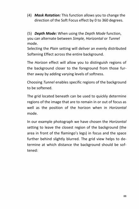
The grid located beneath can be used to quickly determine
regions of the image that are to remain in or out of focus as
well as the position of the horizon when in Horizontal
mode.
In our example photograph we have chosen the Horizontal
setting to leave the closest region of the background (the
area in front of the flamingo’s legs) in focus and the space
further behind slightly blurred. The grid view helps to de-
termine at which distance the background should be sof-
tened:
89
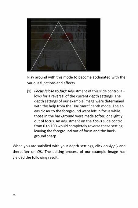
Play around with this mode to become acclimated with the
various functions and effects.
(1) Focus (close to far): Adjustment of this slide control al-lows for a reversal of the current depth settings. The depth settings of our example image were determined with the help from the Horizontal depth mode. The ar-eas closer to the foreground were left in focus while those in the background were made softer, or slightly out of focus. An adjustment on the Focus slide control from 0 to 100 would completely reverse these setting leaving the foreground out of focus and the back-ground sharp.
When you are satisfied with your depth settings, click on Apply and
thereafter on OK. The editing process of our example image has
yielded the following result:
90
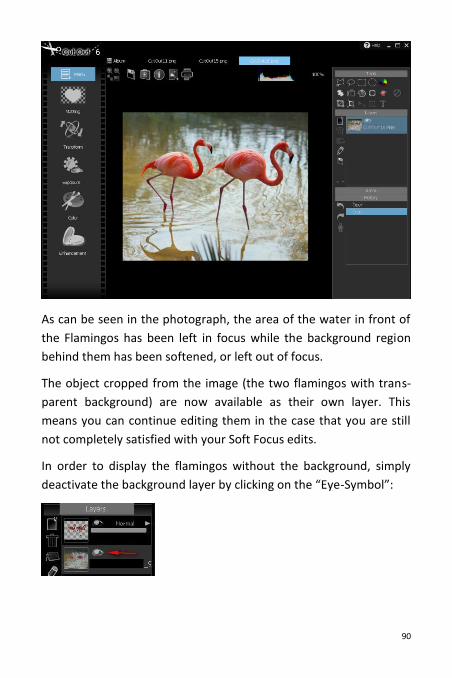
As can be seen in the photograph, the area of the water in front of
the Flamingos has been left in focus while the background region
behind them has been softened, or left out of focus.
The object cropped from the image (the two flamingos with trans-
parent background) are now available as their own layer. This
means you can continue editing them in the case that you are still
not completely satisfied with your Soft Focus edits.
In order to display the flamingos without the background, simply
deactivate the background layer by clicking on the “Eye-Symbol”:
91
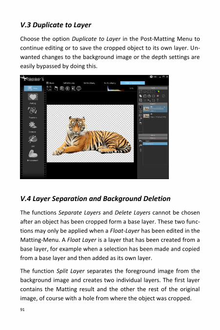
V.3 Duplicate to Layer
Choose the option Duplicate to Layer in the Post-Matting Menu to
continue editing or to save the cropped object to its own layer. Un-
wanted changes to the background image or the depth settings are
easily bypassed by doing this.
V.4 Layer Separation and Background Deletion
The functions Separate Layers and Delete Layers cannot be chosen
after an object has been cropped form a base layer. These two func-
tions may only be applied when a Float-Layer has been edited in the
Matting-Menu. A Float Layer is a layer that has been created from a
base layer, for example when a selection has been made and copied
from a base layer and then added as its own layer.
The function Split Layer separates the foreground image from the
background image and creates two individual layers. The first layer
contains the Matting result and the other the rest of the original
image, of course with a hole from where the object was cropped.
92
The function Delete Background creates an individual layer for the
newly cropped object and deletes the remaining background of the
original image. Should you only need the cropping result and not
the background, this option is the right choice.
VI Photo Editing
In addition to the numerous object cropping possibilities previously
described, Cutout 6 also provides access to a wide array of editing
solutions for photos and cropping objects. You can optimize your
image results with the diverse selection of effects and filters availa-
ble to you as a Cutout 6 user.
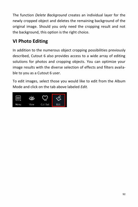
To edit images, select those you would like to edit from the Album
Mode and click on the tab above labeled Edit.
93
VI.1 Editing Mode – Overview
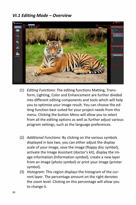
(1) Editing Functions: The editing functions Matting, Trans-form, Lighting, Color and Enhancement are further divided into different editing components and tools which will help you to optimize your image result. You can choose the ed-iting function best suited for your project needs from this menu. Clicking the button Menu will allow you to select from all the editing options as well as further adjust various program settings, such as the language preferences.
(2) Additional Functions: By clicking on the various symbols displayed in box two, you can either adjust the display scale of your image, save the image (floppy disc symbol), activate the Image Assistant (doctor’s kit), display the im-age information (Information symbol), create a new layer from an image (photo symbol) or print your image (printer symbol).
(3) Histogram: This region displays the histogram of the cur-rent layer. The percentage amount on the right denotes the zoom level. Clicking on this percentage will allow you to change it.
94
(4) Help: Refers you to this manual.
(5) Tools: Here you will find the selection tools for specifying regions of the photograph for editing in addition to various other useful editing tools.
(6) Layers: In the Layers-Window you can view all available layers. You can also delete, add, rename, relocate as well as adjust opacity levels and merge layers in this window.
(7) Areas: Here you can take the selected regions made with the selection tool and create a mask to be used on any lay-er of your choice.
(8) Project History: This window displays the previous changes made to your project, therefore allowing you to undo steps or retrieve specific elements. The chronology of work steps in your project can be saved as a Scheme-File and applied to any amount of additional photos via batch processing with one click on the Robot-symbol.
95
VI.2 Editing Mode – Detailed View
VI.2.1 Matting
Please refer to the previous chapters of this manual for detailed
explanations pertaining to Matting and the Matting process in Cut-
out 6.
96
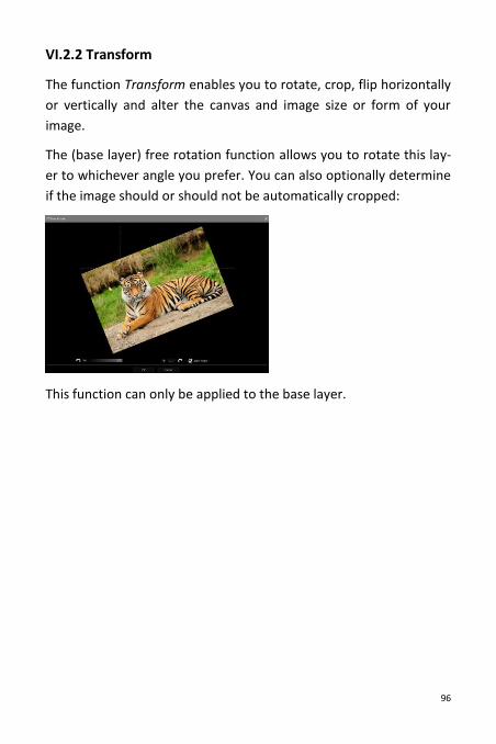
VI.2.2 Transform
The function Transform enables you to rotate, crop, flip horizontally
or vertically and alter the canvas and image size or form of your
image.
The (base layer) free rotation function allows you to rotate this lay-
er to whichever angle you prefer. You can also optionally determine
if the image should or should not be automatically cropped:
This function can only be applied to the base layer.
97
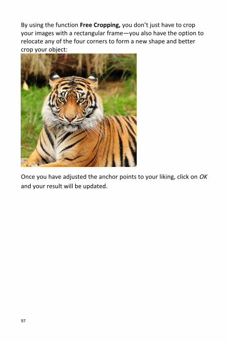
By using the function Free Cropping, you don’t just have to crop your images with a rectangular frame—you also have the option to relocate any of the four corners to form a new shape and better crop your object:
Once you have adjusted the anchor points to your liking, click on OK
and your result will be updated.
98
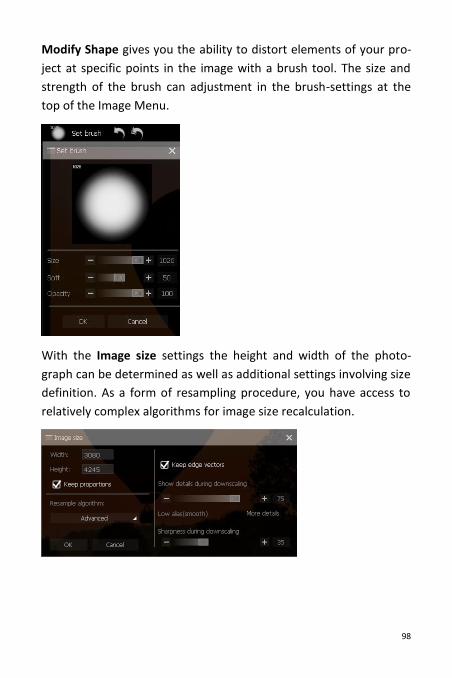
Modify Shape gives you the ability to distort elements of your pro-
ject at specific points in the image with a brush tool. The size and
strength of the brush can adjustment in the brush-settings at the
top of the Image Menu.
With the Image size settings the height and width of the photo-
graph can be determined as well as additional settings involving size
definition. As a form of resampling procedure, you have access to
relatively complex algorithms for image size recalculation.
99
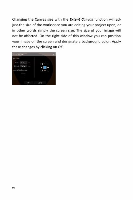
Changing the Canvas size with the Extent Canvas function will ad-
just the size of the workspace you are editing your project upon, or
in other words simply the screen size. The size of your image will
not be affected. On the right side of this window you can position
your image on the screen and designate a background color. Apply
these changes by clicking on OK.
100
VI.2.3 Exposure
More often than not exposure levels in photographs tend to be less
than optimal, either over-illuminated or underexposed. Classic ex-
amples are photographs shot under backlit conditions or in dimly lit
areas. Cutout 6 offers appropriate solutions to just these problems
with its collection of exposure tools.
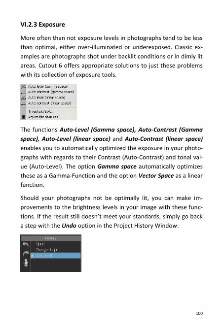
The functions Auto-Level (Gamma space), Auto-Contrast (Gamma
space), Auto-Level (linear space) and Auto-Contrast (linear space)
enables you to automatically optimized the exposure in your photo-
graphs with regards to their Contrast (Auto-Contrast) and tonal val-
ue (Auto-Level). The option Gamma space automatically optimizes
these as a Gamma-Function and the option Vector Space as a linear
function.
Should your photographs not be optimally lit, you can make im-
provements to the brightness levels in your image with these func-
tions. If the result still doesn’t meet your standards, simply go back
a step with the Undo option in the Project History Window:
101
Now moving to the Threshold/BW function: This function trans-
forms your image black-and-white and allows for the specification
of additional settings and characteristics.
The slide control Threshold determines whether areas will appear
black or white depending on their threshold values. For example:
When a high value is selected, or when the slide control is dragged
far to the right, even brighter regions of the original image will ap-
pear black and only very bright regions will remain white. The oppo-
site effect can be seen when the slide control is dragged far towards
the left: Relatively dark regions will in this case appear white and
only very dark regions will remain black.
The slide control Transition Level between Black and White deter-
mines the amount of gray tones found in-between the pure white
and pure black color tones. If you wish for an outcome explicitly
made up of black and white tones, leave the value on the slide con-
trol at zero.
The slide control labeled Size of Adaptive Area will only become
active after selecting the option Adaptive Threshold under the
Methods tab above. There is no global or definite threshold when
using the Adaptive Threshold method, rather there exists a wide
array local thresholds. The slide control is used to determine the
size of these local regions, for each of which an individual threshold
is determined.
102
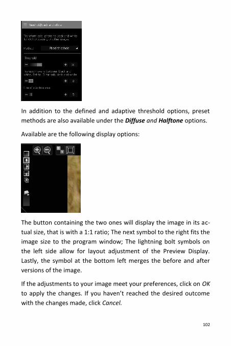
In addition to the defined and adaptive threshold options, preset
methods are also available under the Diffuse and Halftone options.
Available are the following display options:
The button containing the two ones will display the image in its ac-
tual size, that is with a 1:1 ratio; The next symbol to the right fits the
image size to the program window; The lightning bolt symbols on
the left side allow for layout adjustment of the Preview Display.
Lastly, the symbol at the bottom left merges the before and after
versions of the image.
If the adjustments to your image meet your preferences, click on OK
to apply the changes. If you haven’t reached the desired outcome
with the changes made, click Cancel.
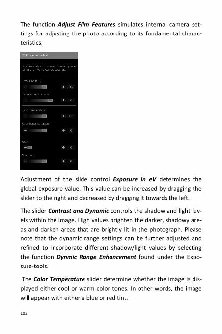
103
The function Adjust Film Features simulates internal camera set-
tings for adjusting the photo according to its fundamental charac-
teristics.
Adjustment of the slide control Exposure in eV determines the
global exposure value. This value can be increased by dragging the
slider to the right and decreased by dragging it towards the left.
The slider Contrast and Dynamic controls the shadow and light lev-
els within the image. High values brighten the darker, shadowy are-
as and darken areas that are brightly lit in the photograph. Please
note that the dynamic range settings can be further adjusted and
refined to incorporate different shadow/light values by selecting
the function Dynmic Range Enhancement found under the Expo-
sure-tools.
The Color Temperature slider determine whether the image is dis-
played either cool or warm color tones. In other words, the image
will appear with either a blue or red tint.
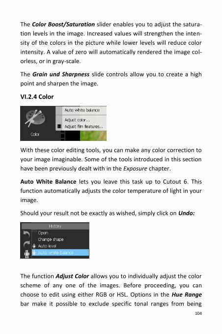
104
The Color Boost/Saturation slider enables you to adjust the satura-
tion levels in the image. Increased values will strengthen the inten-
sity of the colors in the picture while lower levels will reduce color
intensity. A value of zero will automatically rendered the image col-
orless, or in gray-scale.
The Grain und Sharpness slide controls allow you to create a high
point and sharpen the image.
VI.2.4 Color
With these color editing tools, you can make any color correction to
your image imaginable. Some of the tools introduced in this section
have been previously dealt with in the Exposure chapter.
Auto White Balance lets you leave this task up to Cutout 6. This
function automatically adjusts the color temperature of light in your
image.
Should your result not be exactly as wished, simply click on Undo:
The function Adjust Color allows you to individually adjust the color
scheme of any one of the images. Before proceeding, you can
choose to edit using either RGB or HSL. Options in the Hue Range
bar make it possible to exclude specific tonal ranges from being
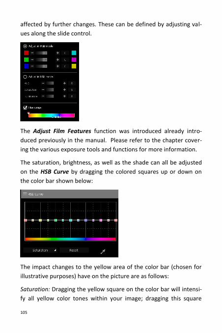
105
affected by further changes. These can be defined by adjusting val-
ues along the slide control.
The Adjust Film Features function was introduced already intro-
duced previously in the manual. Please refer to the chapter cover-
ing the various exposure tools and functions for more information.
The saturation, brightness, as well as the shade can all be adjusted
on the HSB Curve by dragging the colored squares up or down on
the color bar shown below:
The impact changes to the yellow area of the color bar (chosen for
illustrative purposes) have on the picture are as follows:
Saturation: Dragging the yellow square on the color bar will intensi-
fy all yellow color tones within your image; dragging this square
106
downwards will desaturate these yellow regions. Other color ranges
are not affected by these changes.
Brightness: Dragging the yellow square upwards will display all yel-
low color tones brighter within your image; Dragging this square
downwards results in these appearing darker. Other color ranges
are not affected by these changes.
Color tone: Dragging the yellow square down or up on the color bar
will result in all yellow color tones being displayed in another color.
Once you drag the yellow marker on the color bar, you will notice
that its color tone changes. This is the color tone in which all yellow
ranges within the image are displayed. Additional color ranges are
not affected.
The pipette tool allows you to designate any point in the image and
see its color displayed on the color bar.
Reset will undo all the previous changes made. Saturation, bright-
ness and Color tone call all be simultaneously edited. Simply switch
back and before between these properties and the settings will be
kept for each one respectively.
In the following picture, all blue tones have been desaturated so
that the sky appears in gray-scale:
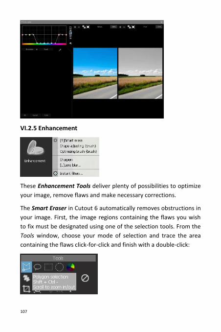
107
VI.2.5 Enhancement
These Enhancement Tools deliver plenty of possibilities to optimize
your image, remove flaws and make necessary corrections.
The Smart Eraser in Cutout 6 automatically removes obstructions in
your image. First, the image regions containing the flaws you wish
to fix must be designated using one of the selection tools. From the
Tools window, choose your mode of selection and trace the area
containing the flaws click-for-click and finish with a double-click:
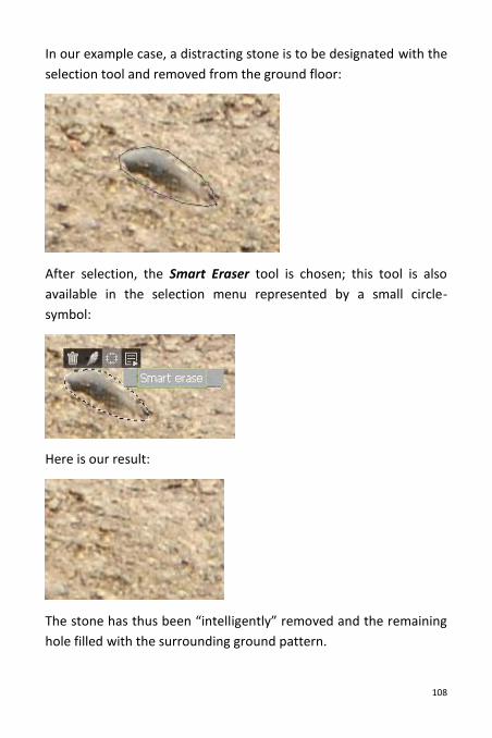
108
In our example case, a distracting stone is to be designated with the
selection tool and removed from the ground floor:
After selection, the Smart Eraser tool is chosen; this tool is also
available in the selection menu represented by a small circle-
symbol:
Here is our result:
The stone has thus been “intelligently” removed and the remaining
hole filled with the surrounding ground pattern.
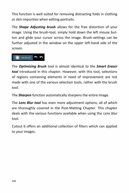
109
This function is well suited for removing distracting folds in clothing
or skin impurities when editing portraits.
The Shape Adjusting brush allows for the free distortion of your
image. Using the brush-tool, simply hold down the left mouse but-
ton and glide your cursor across the image. Brush-settings can be
further adjusted in the window on the upper left-hand side of the
screen.
The Optimizing Brush tool is almost identical to the Smart Eraser
tool introduced in this chapter. However, with this tool, selections
of regions containing elements in need of improvement are not
made with one of the various selection tools, rather with the brush
tool.
The Sharpen function automatically sharpens the entire image.
The Lens Blur tool has even more adjustment options, all of which
are thoroughly covered in the Post-Matting Chapter. This chapter
deals with the various functions available when using the Lens blur
tool.
Cutout 6 offers an additional collection of filters which can applied
to your images.
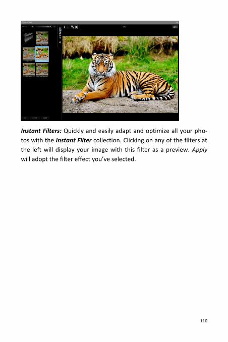
110
Instant Filters: Quickly and easily adapt and optimize all your pho-
tos with the Instant Filter collection. Clicking on any of the filters at
the left will display your image with this filter as a preview. Apply
will adopt the filter effect you’ve selected.
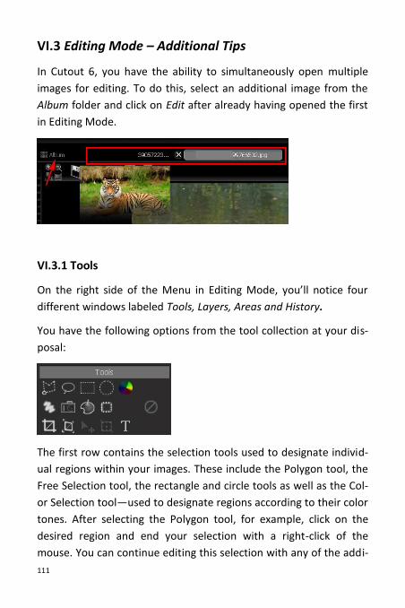
111
VI.3 Editing Mode – Additional Tips
In Cutout 6, you have the ability to simultaneously open multiple
images for editing. To do this, select an additional image from the
Album folder and click on Edit after already having opened the first
in Editing Mode.
VI.3.1 Tools
On the right side of the Menu in Editing Mode, you’ll notice four
different windows labeled Tools, Layers, Areas and History.
You have the following options from the tool collection at your dis-
posal:
The first row contains the selection tools used to designate individ-
ual regions within your images. These include the Polygon tool, the
Free Selection tool, the rectangle and circle tools as well as the Col-
or Selection tool—used to designate regions according to their color
tones. After selecting the Polygon tool, for example, click on the
desired region and end your selection with a right-click of the
mouse. You can continue editing this selection with any of the addi-
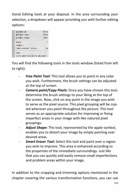
112
tional Editing tools at your disposal. In the area surrounding your
selection, a dropdown will appear providing you with further editing
options:
You will find the following tools in the tools window (listed from left
to right):
- Free Paint Tool: This tool allows you to paint in any color you wish. Furthermore, the brush settings can be adjusted at the top of screen.
- Camera paint/Copy Pixels: Once you have chosen this tool, determine the brush settings to your liking at the top of the screen. Now, click on any point in the image you wish to serve as the pixel source. This pixel grouping will be cop-ied wherever you paint throughout the picture. This tool serves as an appropriate solution for improving or fixing imperfect areas in your image with like-natured pixel groupings.
- Adjust Shape: This tool, represented by the apple-symbol, enables you to distort your image by simply painting over desired areas.
- Smart Eraser Tool: Select this tool and paint over a region you wish to improve. This area is enhanced according to the properties of the immediate surroundings. Just like that you can quickly and easily remove small imperfections and problem areas within your image.
In addition to the cropping and trimming options mentioned in the
chapter covering the various transformation functions, you can use
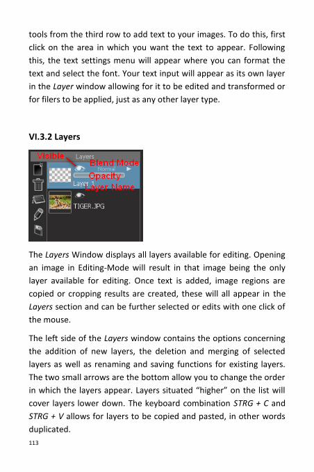
113
tools from the third row to add text to your images. To do this, first
click on the area in which you want the text to appear. Following
this, the text settings menu will appear where you can format the
text and select the font. Your text input will appear as its own layer
in the Layer window allowing for it to be edited and transformed or
for filers to be applied, just as any other layer type.
VI.3.2 Layers
The Layers Window displays all layers available for editing. Opening
an image in Editing-Mode will result in that image being the only
layer available for editing. Once text is added, image regions are
copied or cropping results are created, these will all appear in the
Layers section and can be further selected or edits with one click of
the mouse.
The left side of the Layers window contains the options concerning
the addition of new layers, the deletion and merging of selected
layers as well as renaming and saving functions for existing layers.
The two small arrows are the bottom allow you to change the order
in which the layers appear. Layers situated “higher” on the list will
cover layers lower down. The keyboard combination STRG + C and
STRG + V allows for layers to be copied and pasted, in other words
duplicated.
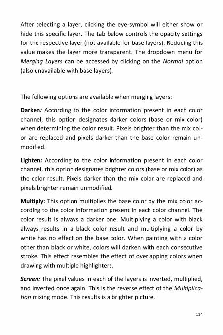
114
After selecting a layer, clicking the eye-symbol will either show or
hide this specific layer. The tab below controls the opacity settings
for the respective layer (not available for base layers). Reducing this
value makes the layer more transparent. The dropdown menu for
Merging Layers can be accessed by clicking on the Normal option
(also unavailable with base layers).
The following options are available when merging layers:
Darken: According to the color information present in each color
channel, this option designates darker colors (base or mix color)
when determining the color result. Pixels brighter than the mix col-
or are replaced and pixels darker than the base color remain un-
modified.
Lighten: According to the color information present in each color
channel, this option designates brighter colors (base or mix color) as
the color result. Pixels darker than the mix color are replaced and
pixels brighter remain unmodified.
Multiply: This option multiplies the base color by the mix color ac-
cording to the color information present in each color channel. The
color result is always a darker one. Multiplying a color with black
always results in a black color result and multiplying a color by
white has no effect on the base color. When painting with a color
other than black or white, colors will darken with each consecutive
stroke. This effect resembles the effect of overlapping colors when
drawing with multiple highlighters.
Screen: The pixel values in each of the layers is inverted, multiplied,
and inverted once again. This is the reverse effect of the Multiplica-
tion mixing mode. This results is a brighter picture.
115
Overlay: The Overlapping Mode is a combination of multiplication
and division. The deciding factor for this mode is the top layer.
However much brighter the colors in the top layer are determines
how bright the colors in the mid tone area will appear. The opposite
can also be applied: However darker the colors in the top layer ap-
pear, all the more darker the mid tones in the bottom layer will ap-
pear. In contrast with Multiplication Mode, the Overlapping func-
tion doesn’t have such a darkening effect.
Hard Light: This mode performs a multiplication, or in some cases, a
negative multiplication, of the colors (independent of the mix col-
or). The effect resembles the effect of a spotlight shone directly on
the image. If the mix color (light source) has a brightness level ex-
ceeding that of 50% of gray, the image will be brightened. If the mix
color has a brightness level darker than that of 50% of gray, the im-
age will be darkened (similar to the after-exposure effect).
Soft Light: Colors are either lightened or darkened depending on
the mix color. The effects resembling the indirect illumination of the
image with a spotlight. If the mix color (light source) has a bright-
ness level exceeding that of 50% of gray, the image will be bright-
ened. If the mix color has a brightness level darker than that of 50%
of gray, the image will be darkened (similar to the after-exposure
effect). Mixing using pure white or black will not result in pure white
or black, rather a relatively darker or lighter outcome.
Difference: This mode subtracts the color (base or mix color) pos-
sessing the lowest brightness level with the color from that pos-
sessing the highest brightness level according to the color infor-
mation present in each channel. In this case, mixing with white re-
sults in an inversion of the color values of the base color. Mixing
with black yields no change.
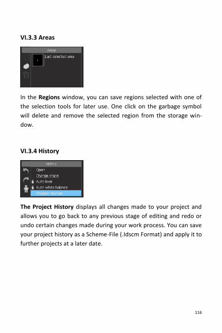
116
VI.3.3 Areas
In the Regions window, you can save regions selected with one of
the selection tools for later use. One click on the garbage symbol
will delete and remove the selected region from the storage win-
dow.
VI.3.4 History
The Project History displays all changes made to your project and
allows you to go back to any previous stage of editing and redo or
undo certain changes made during your work process. You can save
your project history as a Scheme-File (.Idscm Format) and apply it to
further projects at a later date.
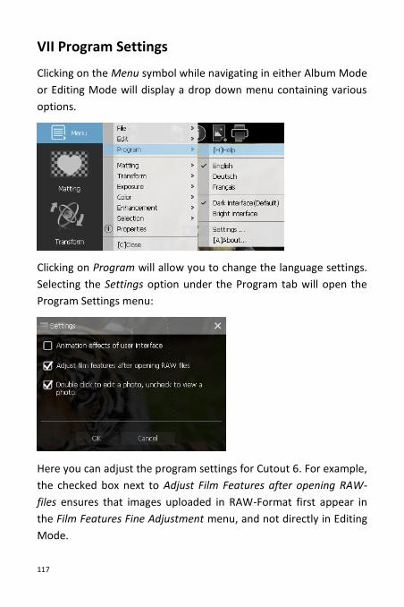
117
VII Program Settings
Clicking on the Menu symbol while navigating in either Album Mode
or Editing Mode will display a drop down menu containing various
options.
Clicking on Program will allow you to change the language settings.
Selecting the Settings option under the Program tab will open the
Program Settings menu:
Here you can adjust the program settings for Cutout 6. For example,
the checked box next to Adjust Film Features after opening RAW-
files ensures that images uploaded in RAW-Format first appear in
the Film Features Fine Adjustment menu, and not directly in Editing
Mode.
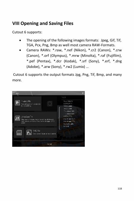
118
VIII Opening and Saving Files
Cutout 6 supports:
The opening of the following images formats: Jpeg, Gif, Tif, TGA, Pcx, Png, Bmp as well most camera RAW-Formats.
Camera RAWs: *.raw, *.nef (Nikon), *.cr2 (Canon), *.crw
(Canon), *.orf (Olympus), *.mrw (Minolta), *.raf (Fujifilm),
*.pef (Pentax), *.dcr (Kodak), *.srf (Sony), *.erf, *.dng
(Adobe), *.arw (Sony), *.rw2 (Lumix) …
Cutout 6 supports the output formats Jpg, Png, Tif, Bmp, and many
more.
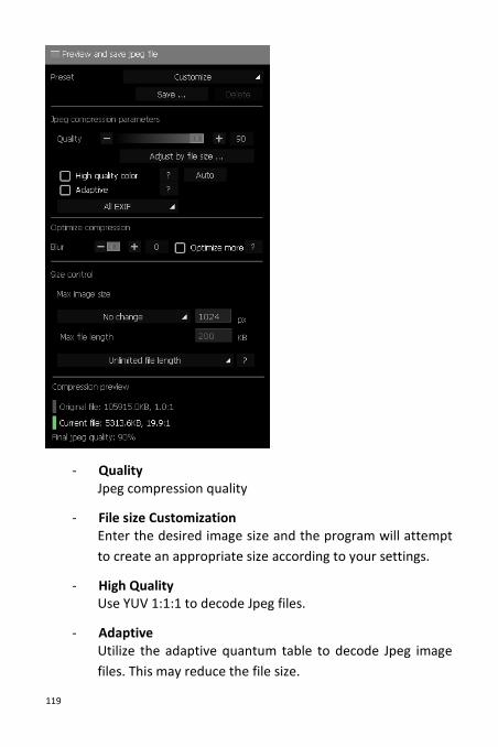
119
- Quality Jpeg compression quality
- File size Customization Enter the desired image size and the program will attempt
to create an appropriate size according to your settings.
- High Quality Use YUV 1:1:1 to decode Jpeg files.
- Adaptive Utilize the adaptive quantum table to decode Jpeg image
files. This may reduce the file size.
120
- Exif-Data Choose whether all, some or none of the EXIF-Data are to
be kept in the file. EXIF-Data require a file size of 1-64K.
- Compression Optimization The program will attempt to reduce the file size by means
of optimization.
- Maximum Image Size Set an image size limit. If this is exceeded, the image will be
automatically reduced.
- Maximum File Size Set a file size limit.
- Methods When the final file size exceeds the maximum file size, the
program selects a method to reduce the file size. The
method encompasses a down-scaling of the image size and
a quality reduction. The size reduction process is carried
out automatically.

121
Hotline/Support
Contact the FRANZIS Customer Service Team for questions about installation, problems or disruptions concerning this software product. E-Mail: [email protected] Please bear in mind that your inquiries can only be handled by the FRANZIS Customer Service Support Team. This is how we can continue to make lasting improvements in our service quality while answering your questions quickly and professionally. Customer Service quick and easy: Have important information concerning your PC system and product ready:
Product Name
Operating System of your PC
Information about your PC’s Configuration
122
Copyright
Franzis Verlag GmbH has taken great care in producing this product. Please acknowledge the following provisions: The following programs, routines, controls etc. located on this data storage medium or in this download are copyright protected by the producer or distributor as stated in the respective programs. The recipient of this storage medium or download reserves the right to use the programs, data or data groups not designated as Shareware or Public Domain for his or her own personal use appropriately and in accordance with the listed provisions. Programs or program elements designated as Shareware, Freeware or Public Domain may be used by the recipient in accordance with the rules and restrictions stated in each program or program element. The duplication of programs with the intent of distribution or sale of storage mediums containing the programs is not allowed. Franzis Verlag GmbH reserves the right for the selection, arrangement and classification of programs and data located on this storage medium or in this download. The data and programs saved to this storage medium or within this download have been carefully reviewed. With regard to the high amount of data and programs, Franzis guarantees neither the correctness of data nor the error-free function of the programs. Neither the publisher nor Franzis offers any guarantee or takes judicial responsibility for the use of individual files or information, for their profitability or error-free use for any specific purpose. There is also no guarantee for the unrestricted use of all data, programs, icons, sounds or additional files contained in this product. Accordingly, the publishing company cannot be made responsible for the violation of patent or other rights of third parties. The majority of the product labeling of hardware and software as well as company names and logos listed in this work are also trademarks and should be viewed as such. The publisher has taken great care in following the notation used by the original producers. © 2016 Franzis Verlag GmbH, Richard-Reitzner-Allee 2, 85540 Haar near München