Embed Size (px)
Citation preview

CUTTING TOOLSSolutions For The Aerospace Industry
www.ngkntk.de/ntk/dewww.ntkcuttingtools.co.ukwww.ngkntk.co.jp

●Excellent notch wear resistance
●For machining of Aerospace alloys Inconel , Waspalloy , Hastelloy and also Stellite
SiAlON ceramics
SX9, SX5
●For stable machining
Double clamp, Top clamp
Tool Holder
●ZM3 with sharp cutting edge
●QM3 for heavy machining
ZM3, QM3PVD coated micro grain carbide
Turning
P.08
P.21
P.10
CUTTING TOOLS
2

Tool Holder●Excellent surface finish
Whisker ceramics
●Excellent wear resistance
●High productivity with high cutting speed
WA1
●High performance milling with awide variety of cutters
Profiling & Grooving
Milling
P.33
P.09
P.39
3
4
Guide to This Catalogue
This catalogue lists products as of February 2009.
Inventory status symbols:● : Service stock for left- and right- handed products and neutral
products.○ : Custom made product.
------------------Safety Notice------------------
We make a particular effort to manufacture safe products. However,NTK cutting tools may be broken due to a sudden increase of the cut-ting load or excessive tool wear, which could possibly cause injuries tooperators. To protect the operators from such accidents, please notethe following when operating a cutting tool:
◎ Install shielding plates or wear protective clothes andglasses.
◎ Do not touch the cutting edge with bare hand because itis sharp.
◎ Use genuine NTK parts for parts and drivers, etc.◎ Check sharpness and replace the tool early if necessary.◎ Check the sharpness of tools and exchange them at an
early stage.
We do not recommend you to grind cutting tools because grinding maycause cracks and improper finishing, possibly resulting in breakage ofthe tool.
WARNING

CONTENTSGrade
Selection
Stock
Turning /Boring
Profiling&Grooving
Milling
TechnicalInformation
Index
Inse
rtTo
olin
g
6
11
21
33
39
43
61
5

Rough scale Rough & Semi-Finish
Profiling Finish
Grooving Milling
6
Grade SelectionG
rade
Sel
ectio
n
500
400
300
200
100
0Light Interrupted InterruptedContinuous
Cut
ting
Spe
ed(
m/m
in) WA1
ZM3,QM3
SX9
SX5
7
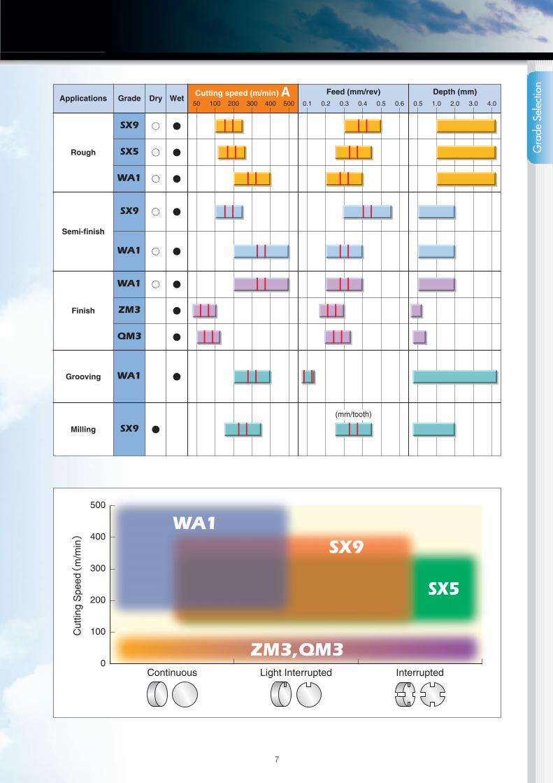
Applications Grade Dry WetCutting speed (m/min) A Feed (mm/rev) Depth (mm)
Rough
SX9
SX5
WA1
○
○
○
●
●
●
Semi-finish
SX9
WA1
○
○
●
●
Finish
WA1
ZM3
QM3
○ ●
●
●
Grooving
Milling
WA1
SX9 ●
●
50 100 200 300 400 500 0.1 0.2 0.3 0.4 0.5 0.6 0.5 1.0 2.0 3.0 4.0
Gra
de S
elec
tion
(mm/tooth)
8
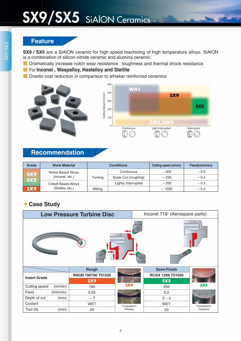
SiAlON CeramicsSX9/SX5Feature
SX9 / SX5 are a SiAlON ceramic for high speed machining of high temperature alloys. SiAlONis a combination of silicon nitride ceramic and alumina ceramic.■ Dramatically increase notch wear resistance , toughness and thermal shock resistance■ For Inconel , Waspalloy, Hastelloy and Stellite■ Drastic cost reduction in comparison to whisker reinforced ceramics
500
400
300
200
100
0Light Interrupted InterruptedContinuous
Cut
ting
Spe
ed(
m/m
in) WA1
ZM3,QM3
SX9
SX5
蘆Case Study
Grade Work Material Conditions Cutting speed (m/min) Feed(mm/rev)
SX9SX5
SX9
Nickel Based Alloys(Inconel, etc.)
Cobalt Based Alloys(Stellite, etc.)
Turning
Milling
Continuous
Scale Cut (roughing)
Lightly Interrupted
– 300
– 230
– 200
– 1000
– 0.5
– 0.4
– 0.3
– 0.2
Low Pressure Turbine Disc
Cutting speed (m/min)
Feed (mm/rev)
Depth of cut (mm)
Coolant
Tool life (min)
Insert Grade
Rough
RNGN 190700 T01020
SX9180
0.25
– 7
WET
20
Semi-Finish
RCGX 1208 T01020
SX5250
0.2
2 – 3
WET
20
Inconel 718 (Aerospace parts)
SX9
Competitor'sWhisker
SX5
Competitor'sCeramics
SX9/
SX5
Recommendation

Grooving
VGW8375-2 E002
WA1300
0.1
–
WET
20
Ramping
RPGX 0908 T00520
WA1300
0.06
2 – 3
WET
20
9
Whisker CeramicsWA1Feature
WA1 is a whisker-reinforced ceramic material with silicon-carbide whisker added to alumina, themain compornent Alumina ceramic offers the best wear resistance at high cutting speeds.■ Toughness and notch wear resistance dramatically increases■ Whisker-reinforcing technology for Heat-resistant alloys
500
400
300
200
100
0Light Interrupted InterruptedContinuous
Cut
ting
Spe
ed(
m/m
in) WA1WA1
ZM3,QM3
SX9
SX5
蘆Case Study
Grade Work Material Conditions Cutting speed (m/min) Feed(mm/rev)
WA1
Nickel Based Alloys(Inconel, etc.)
Cobalt Based Alloys(Stellite, etc.)
Turning
Continuous
Scale Cut (roughing)
Lightly Interrupted
– 500
– 300
– 200
– 1000
– 0.5
– 0.4
– 0.3
– 0.2
Ring for bearing housing
Cutting speed (m/min)
Feed (mm/rev)
Depth of cut (mm)
Coolant
Tool life (min)
Insert Grade
Outside Turning
RNGN 120700 T00520
WA1300
0.15
3 – 4
WET
20
Inconel 718 (Aerospace parts)
WA
1
Recommendation
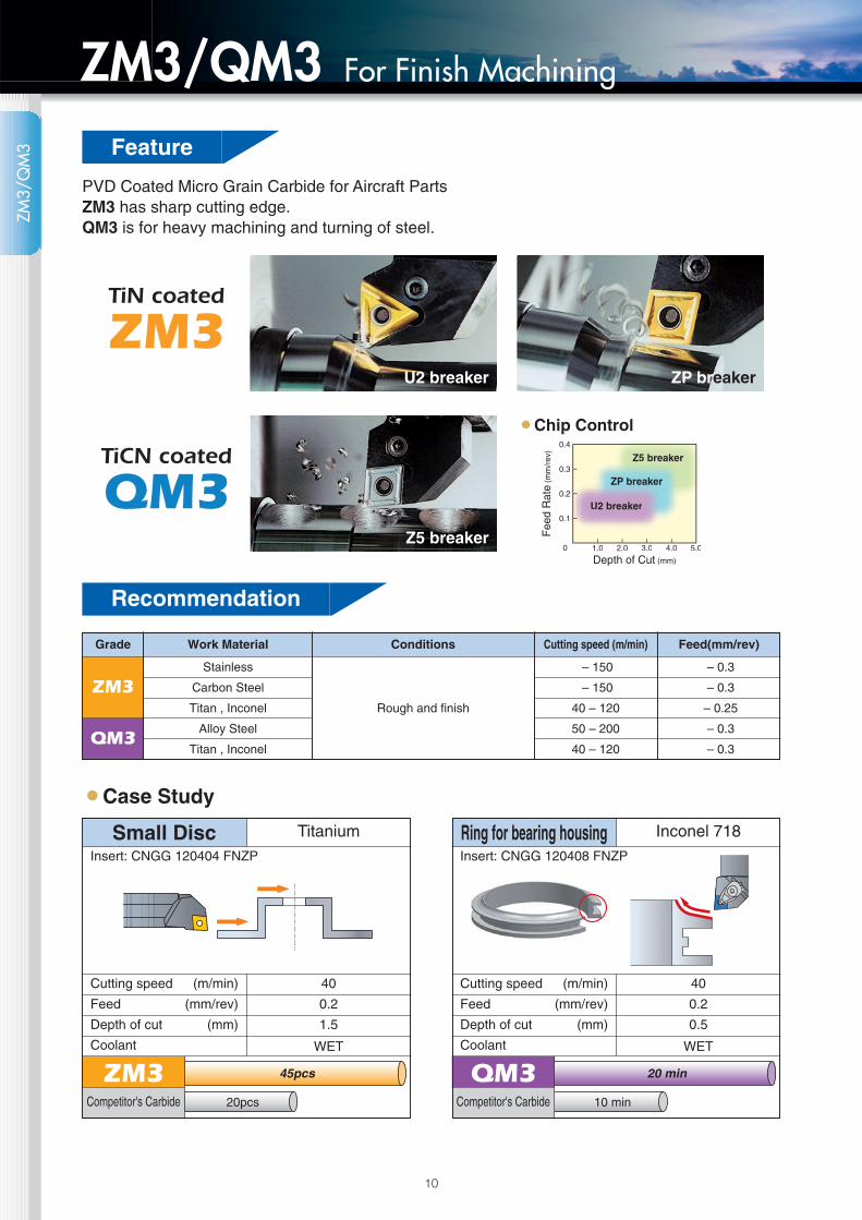
20 min
10 min
45pcs
20pcs
10
For Finish MachiningZM3/QM3
PVD Coated Micro Grain Carbide for Aircraft PartsZM3 has sharp cutting edge.QM3 is for heavy machining and turning of steel.
蘆Case Study
Z5 breaker
ZP breakerU2 breaker
0 1.0
0.1
0.2
0.3
0.4
2.0 3.0 4.0 5.0
Depth of Cut (mm)
Fee
d R
ate
(mm
/rev
)
U2 breaker
ZP breaker
Z5 breaker
蘆Chip Control
ZM3Competitor's Carbide
Small DiscInsert: CNGG 120404 FNZP
Cutting speed (m/min)
Feed (mm/rev)
Depth of cut (mm)
Coolant
40
0.2
1.5
WET
Titanium
TiN coated
ZM3
TiCN coated
QM3
Grade Work Material Conditions Cutting speed (m/min) Feed(mm/rev)
ZM3
QM3
Stainless
Carbon Steel
Titan , Inconel
Alloy Steel
Titan , Inconel
Rough and finish
– 150
– 150
40 – 120
50 – 200
40 – 120
– 0.3
– 0.3
– 0.25
– 0.3
– 0.3
QM3Competitor's Carbide
Ring for bearing housingInsert: CNGG 120408 FNZP
Cutting speed (m/min)
Feed (mm/rev)
Depth of cut (mm)
Coolant
40
0.2
0.5
WET
Inconel 718
ZM3/
QM
3 Feature
Recommendation

Insert Stock List

70°-90°
70°-90°
40°-60°
40°-60°
12
S TC
D K
φd
m m
φd s
1 Shape
C 80°
D 55°
E 75°
L
P
R
S
T
V 35°
W 80°
3 Tolerance Class
Symbol d (mm) m (mm) s (mm)
M tolerance
Inscribed Circle d (mm)
6.35
9.525
12.7
15.875
19.05
25.40
±0.05
±0.05
±0.08
±0.10
±0.10
±0.13
m (mm)
±0.08
±0.08
±0.13
±0.15
±0.15
±0.18
A
F
C
H
E
G
J
K
L
M
N
U
±0.025
±0.013
±0.025
±0.013
±0.025
±0.025
±0.05
±0.05~±0.13
±0.05~±0.13
±0.05~±0.13
±0.05~±0.13
±0.08~±0.25
±0.005
±0.005
±0.013
±0.013
±0.025
±0.025
±0.05
±0.013
±0.025
±0.08~±0.18
±0.08~±0.18
±0.13~±0.38
±0.025
±0.025
±0.025
±0.025
±0.025
±0.13
±0.13
±0.025
±0.025
±0.13
±0.025
±0.13
2 Clearances 4 Type
0°
5°
7°
11°
15°
20°
N
B
C
P
D
E
Type
Specialdesign
≦6.35mm
Symbol
N
F
R
A
G
M
X
Inscribed Circle(Including 7.94mm)≦5.56mm
E
L
S
D
K
P
X
Type
Symbol
Inscribed Circle≦6.35mm
H
B
T
W
6 Thickness
Thick-nessS(mm)
3.18
4.76
6.35
7.94
9.52
12.70
Inch
Metric
03
04
06
07
09
12
Normal≧6.35(mm)
2
3
4
5
6
8
Small≦5.556
4
6
SInch N G A1 2 3 4
SMetric N G A
d (mm)
6.35
9.525
12.7
15.875
19.05
±0.05
±0.05
±0.08
±0.10
±0.10
m (mm)
±0.11
±0.11
±0.15
±0.15
±0.18
Insert Identification SystemIn
sert
Iden
tifica
tion
Syste
m

13
R
C D R S T V W
InscribedCircle(mm)
3.97
4.76
5.56
6.35
7.94
9.525
12.7
15.875
19.05
22.23
25.40
31.75
Inch Metric
Small-sizeseries
Normalseries
5
6
7
(8)
0
-
-
-
-
-
-
-
04
05
06
08
09
12
16
19
22
25
32
04
05
06
07
09
11
15
19
23
27
31
38
03
04
05
06
07
09
12
15
19
22
25
31
06
08
09
11
13
16
22
27
33
38
44
54
09
11
13
16
22
27
33
38
44
54
02
L3
03
04
05
06
08
10
13
17
-
-
-
2
-
3
4
5
6
7
8
03
5 Cutting Edge Length 7 Nose RadiusCorner Radius
※M0 = Round insert (Metric)※00 = Round insert (Inch)
Inch Metric
RoundInsert
Sharp
0.2
0.4
0.8
1.2
1.6
2.0
2.4
2.8
3.2
0
y
1
2
3
4
5
6
7
8
M0(※)
00(※)
00
02
04
08
12
16
20
24
28
32
8 Edge Condition
Sharp F
Chamfered T
Honed E
Chamferedand Honed
SpecialHoned
DoubleChamfer
S
Z
K
P
4 3 3 T 04 205 6 7 8 9 10
12 04 12 T 010 20
b
metric inch a (mm) r (mm)
T
E
S
Z
005
010
015
020
002
004
010
015
010
015
02
04
06
08
01
02
04
06
04
06
0.05
0.1
0.15
0.2
-
-
0.1
0.15
0.1
0.15
-
-
-
-
0.02
0.04
0.04
0.04
0.02
0.02
ar
9 Negative land width 10 Negative land angle
Description b˚
15
20
25
30
15˚
20˚
25˚
30˚
Inse
rt Id
entif
icatio
n Sy
stem

ShapeNTK Part Number Dimensions Ceramics
Metric E.P. IC T R SX9 SX5 WA1
14
Insert Stock List
CNGA 120408
120412
120416
160612160616190612
190616CNGN 120408
120412
120416120708120712160712160716190624
DNGA 150408
150412
150416
150424
T00520T01020T00520T01020T00520T01020T00520T01020T00520T01020T00520T00520T01020T00520T01020T00520T00520T00520T00520T00520T00520T00520T01020T00520T01020T00520T01020T00520T01020
DNGN 150408
150412
150416
150708
150712
190612
T00520T01020T00520T01020T00520T01020T00520T02020T00520T02020T00520
RCGX 060400060700090700
120700
T00520T00520T00520T01020T00520T01020
12.7 4.76
15.88
6.3519.05
12.7
15.88
19.05
4.76
7.94
6.35
12.7 4.76
12.7
4.76
7.94
15.88 6.35
6.354.76
7.949.525
12.7
0.8
1.2
1.6
1.21.6
1.2
1.6
0.8
1.2
1.60.8
1.2
1.62.4
0.8
1.2
1.6
2.4
0.8
1.2
1.6
0.8
1.2
--
-
-
●
○
●
○
●
○
○
○
○
○
○
●
○
●
○
●
○
○
○
○
○
●
○
●
○
●
○
○
○
●
○
●
○
●
○
○
○
○
○
○
○
○
●
○
●
○
○
○
○
○
○
○
○
○
○
○
○
○
○
○
○
○
○
●
○
○
○
○
○
○
○
○
○
○
○
○
○
○
○
○
○
○
○
○
○
○
○
○
○
○
●
○
○
○
○
○
○
○
○
○
○
○
○
○
●
●
●
●
●
●
○
●
○
○
○
○
○
○
○
○
○
○
○
●
○
○
○
○
●
●
●
●
○
●
●
●
●
●
●:Stock ○:Available E.P. : Edge Preparation
Inse
rt St
ock
List
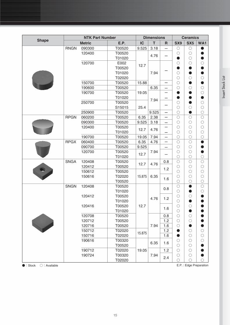
●:Stock ○:Available E.P. : Edge Preparation
ShapeNTK Part Number Dimensions Ceramics
Metric E.P. IC T R SX9 SX5 WA1RNGN 090300
120400
120700
150700190600190700
250700
250900RPGN 060200
090300120400
190700RPGX 060400
090700120700
SNGA 120408120412150612150616
SNGN 120408
120412
120416
120708120712120716150712150716190616
190712190724
T00520T00520T01020E002
T00520T01020T02020T00520T00520T00520T01020T00520S15015T00520T00520T00520T00520T01020T00520T00520T00520T00520T01020T00520T00520T00520T02020T00520T00520T01020T00520T01020T00520T01020T00520T00520T00520T02020T02020T00320T00520T02020T00320T02020
9.525
12.7
15.88
19.05
25.4
6.359.525
12.7
19.056.359.525
12.7
12.7
15.875
12.7
15.875
19.05
3.18
4.76
7.94
6.35
7.94
9.5252.383.18
4.76
7.944.76
7.94
4.76
6.35
4.76
7.94
6.35
7.94
-
-
-
-- - -
-
- - - - - - - -
-
0.8
1.2
1.6
0.8
1.2
1.6
0.81.21.61.21.6
1.6
1.2
2.4
○
○
●
○
●
○
○
○
○
●
●
○
○
○
○
○
○
○
○
○
○
○
○
○
○
○
○
○
○
○
○
○
○
○
○
○
○
●
●
○
○
○
○
○
○
○
○
○
●
●
○
●
○
●
●
●
○
●
○
○
○
○
○
○
○
○
○
○
○
○
○
○
●
●
○
●
○
●
○
○
●
○
○
○
○
○
○
○
●
●
●
○
●
●
○
●
○
○
●
○
○
○
○
○
○
○
○
●
●
●
○
○
○
○
○
○
○
○
●
●
●
●
●
●
●
○
○
○
●
●
●
○
15
Inse
rt St
ock
List

ShapeNTK Part Number Dimensions Ceramics
Metric E.P. IC T R SX9 SX5 WA1
TNGA 220408 T00520
TNGN 160404
160408
160412
220408
220412
220416
220708
220712
270616
T01020
T01020
T01020
T00520
T01020
T00520
T00520
T00520
T00520
T00320
TPGN 160308
160312
220408
220412
220416
T00520
T00520
T00520
T00520
T00520
VNGA 160404
160408
160412
220424
T00520
T00520
T00520
T01020
WNGA 080408
080412
080416
T00520
T00520
T01020
12.7 4.76
9.525
4.76
12.7
7.94
15.88 6.35
9.525 3.18
12.7 4.76
9.5254.76
12.7
12.7 4.76
0.8
0.4
0.8
1.2
0.8
1.2
1.6
0.8
1.2
1.6
0.8
1.2
0.8
1.2
1.6
0.4
0.8
1.2
2.4
0.8
1.2
1.6
○
○
○
○
○
○
○
○
○
○
○
○
○
○
○
○
○
○
○
○
○
○
○
○
○
○
○
○
○
○
○
○
○
○
○
○
○
○
○
○
○
○
○
○
○
○
○
●
●
●
○
○
●
●
○
○
○
○
○
○
○
○
○
○
○
○
○
○
○
●:Stock ○:Available E.P. : Edge Preparation
16
Insert Stock ListIn
sert
Stoc
k Li
st

17
ShapeNTK Part Number Dimensions Ceramics
Metric W R T L SX9 SX5 WA1VGK 8250-2
8312-R8312-28312-48375-28375-4
VGW 4125-R4125-14125-24156-R4156-14156-24187-R4187-14187-26250-R6250-16250-26250-36281-R6281-16281-26281-38312-R8312-18312-28312-38312-48344-R8344-18344-28344-38344-48375-R8375-18375-28375-38375-4
0.8FULL-R
0.81.60.81.6
FULL-R 0.40.8
FULL-R 0.40.8
FULL-R0.40.8
FULL-R 0.40.81.2
FULL-R 0.40.81.2
FULL-R 0.40.81.21.6
FULL-R 0.40.81.21.6
FULL-R 0.40.81.21.6
6.35
7.92
9.525
3.18
3.96
4.75
6.35
7.14
7.92
8.74
9.525
8.33
4.75
6.35
8.56
25.4
12.7
19.05
25.4
○
○
○
○
○
○
○
○
○
○
○
○
○
○
○
○
○
○
○
○
○
○
○
○
○
○
○
○
○
○
○
○
○
○
○
○
○
○
○
○
○
○
○
○
○
○
○
○
○
○
○
○
○
○
○
○
○
○
○
○
○
○
○
○
○
○
○
○
○
○
○
○
○
○
○
○
○
○
○
○
○
○
●
●
●
●
●
●
●
●
●
●
●
●
●
●
○
○
○
●
○
●
○
●
●
○
○
○
○
●
○
●
○
●
●:Stock ○:Available E.P. : Edge Preparation
L
W
r
r
90°
T
FULL RADIUS 11°
Inse
rt St
ock
List
Standard Edge Preparation for WA1 is EX0001 which means 0.05mm or less honing only.Standard Edge Preparation for SX5 & SX9 are T00520 chamfer only.Standard Edge Preparations are not listed in this grooving inserts.

18
Insert Stock List
Shape NTK Part NumberDimensions
IC T RZM3 QM3
CNGG 120404 FN ZP
120408 FN ZP
CNMG 120408 TNB Z5
12.7
12.7
4.76
4.76
0.4
0.8
0.8
●
●
●
●
○ ●
DNGG 150404 FN ZP
150408 FN ZP12.7 4.76
0.4
0.8
●
●
●
●
DNMG 150404 TN G 12.7 4.76 0.4 ○ ○
DNMG 150408 TNB Z5 12.7 4.76 0.8 ○ ●
SNMG 120408 TNB Z5 12.7 4.76 0.8 ○ ●
TNGG 160402 FR C 9.525 4.76 0.2 ○ ○
TNGG 160401 FR DA 9.525 4.76 0.1 ○ ○
TNGG 160401 FR U2
160402 FR U2
160404 FR U2
160408 FR U2
160402 FL U2
160404 FL U2
160408 FL U2
9.525 4.76
0.1
0.2
0.4
0.8
0.2
0.4
0.8
●
●
●
●
○
●
●
○
○
○
○
○
○
○
●:Stock ○:Available E.P. : Edge Preparation
Inse
rt St
ock
List

19
Shape NTK Part NumberDimensions
IC T RZM3 QM3
TNGG 160402 FN ZP
160404 FN ZP
160408 FN ZP
TNMG 160404 TNB Z5
160408 TNB Z5
9.525
9.525
4.76
4.76
0.2
0.4
0.8
0.4
0.8
○
●
●
●
●
●
○
○
○
○
VNGG 160402 FN ZP
160404 FN ZP
160408 FN ZP
9.525 4.76
0.2
0.4
0.8
○
○
○
●
●
○
VNMG 160404 TNB AM1
160408 TNB AM19.525 4.76
0.4
0.8
○
○
○
○
WNGG 080404 FN ZP
080408 FN ZP12.7 4.76
0.4
0.8
○
○
●
●
WNMG 080408 TNB Z5
080412 TNB Z512.7 4.76
0.8
1.2
○
○
○
○
●:Stock ○:Available E.P. : Edge Preparation
Inse
rt St
ock
List
20

Holder Turning / Boring

22
Tur
ning
Turning
L2
L1
b
hh1
CRDC
• Holders and Applicable Inserts
ToolholderDimensions (mm)
h b L1 h1 L2
25
25
25
32
32
32
32
32
32
25
25
25
25
25
25
32
32
32
150
150
150
170
170
170
170
170
170
25
25
25
32
32
32
32
32
32
20
20
25
20
20
25
30
42
42
Insert
RCGX / RPGX 0607
RCGX / RPGX 0907
RCGX / RPGX 1207
RCGX / RPGX 0607
RCGX / RPGX 0907
RCGX / RPGX 1207
RCGX / RPGX 1510
RCGX / RPGX 1910
RCGX / RPGX 2512
RCGN 0607
RCGN 0907
RCGN 1207
RCGN 0607
RCGN 0907
RCGN 1207
CRDCN 2525M062525M092525M123225P063225P093225P123232P153232P193232P25
Shape NTK Part Number
RCGX / RPGX 060700090700120700151000191000251200
Dimensions (mm)d
6.359.52512.70
15.87519.0525.4
s
7.94
9.52
12.70
θ
120°
Shape NTK Part Number dRCGN 060700
090700120400120700
6.359.52512.7012.70
s
7.94
4.767.94
ShimHARCGN 0607-15
0907-151204-151207-15
s
θ
7°
dd
7°
s
• Inserts
Parts
Toolholder
Clamp Shim Clampingscrew
SpringPin Washer Wrench
HC35KR-4099HC35KR-6075HC35KR-6076
CC08MCC08MAMS-10
HARCGX06HARCGX0908VHARCGX1208VHARCGX1510VHARCGX1910VHARCGX2512V
BS0520BS0625BS0625
BS0835WBS0835WAOB-10S
2X8AW2.5X8AW2.5X8AW2.5X8AW2.5X8AW
WS-5WS-6WS-6SR08SR08
LW-3LW-4LW-4LW-4LW-4LW-6
CRDCN3225P06 / 2525M06CRDCN3225P09 / 2525M09CRDCN3225P12 / 2525M12CRDCN3232P15CRDCN3232P19CRDCN3232P25
• Parts

23
Tur
ning
L2
ff
L1
hb
h1
8°
CRDN
• Holders and Applicable Inserts
ToolholderDimensions (mm)
h=h1 b L1 L2 f
25
32
20
25
25
32
32
25
32
32
25
25
20
20
25
25
32
25
25
25
150
170
125
150
150
170
170
150
170
170
25
30
34
34
34
34
34
40
40
40
12.5
12.5
10
10
12.5
12.5
16
12.5
12.5
12.5
Insert
RNGN0904 RNGN0907
RNGN1207RNGN1204
RNGN1507RNGN1504
RNGN1907RNGN1904
CRDNN 2525M093225P092020K122520M122525M123225P123232P122525M153225P153225P19
Clamp
CC08MS
CC08M
BS0835W
BS0829W
BS0835W
ARN32
ARN42
HARN52
HARN62
M3×12
M4×12
SR08 LW-4
Clampingscrew Shim Shim
screw Washer WrenchParts
Toolholder
CRDNN 2525M093225P092020K122520M122525M123225P123232P122525M153225P153225P19
• Parts

Tur
ning
Turning
24
L2
5°
f
L1
b
hh
6° 6°
• Right hand shown.
CRGN
• Holders and Applicable Inserts
Toolholder
Dimensions (mm)
h b L1 L2 f
Shim Shimscrew Clamp Clamp
Screw
20
25
25
25
32
32
20
20
25
25
25
25
125
150
150
170
170
170
30
30
30
30
32
33
25
25
32
32
32
32
ARN42 M3×12
CC08M
BS0829W
BS0835W
HARN52
HARN62M4×8
Insert
RNGN1204
RNGN1204
RNGN1207
RNGN1504 / RNGN1507
RNGN1904 / RNGN1907
CRGNR/L 2020 K12
2520 M12
2525 M12
3225 P12
3225 P15
3225 P19

Tur
ning
25
WCLN
f
L2
95°
L1
6°
b
h1 h
R
l1
f6°
• Right hand shown.
*Conform to master insert which has 0.8mm corner R.・A holder comes with two shims. An insert 7.94 mm thick can likewise be mounted by removing one shim.
WCBN
b
h
75°
L2
L1
f
h1
6°
R
f
l1
6°
• Right hand shown.
• Holders and Applicable Inserts
Toolholder
Dimensions (mm)
h b L1 h1 f L2
25
32
25
25
150
170
25
32
22
22
32
32
Insert
CNGA1204 CNGA1207WCBNR/L2525M12
3225P12
*Conform to master insert which has 0.8mm corner R.・A holder comes with two shims. An insert 7.94 mm thick can likewise be mounted by removing one shim.
• Holders and Applicable Inserts
Toolholder
Dimensions (mm)
h b L1 h1 f L2
25
32
25
25
150
170
25
32
32
32
32
32
Insert
CNGA1204 CNGA1207WCLNR/L 2525M12
3225P12

Tur
ning
Toolholder
Dimensions (mm)
h b L1 h1 f L2
25
32
32
25
25
32
150
170
170
25
32
32
32
32
39
32
32
32
Insert
DNGA1504 DNGA1507
WDJNR/L 2525M15
3225P15
3232P15
Turning
26
WDJN
b
93°
L2
L1
6°
f
6° R
l
f
hh1
• Right hand shown.
WDNN
L2
L1
h1
b
f
10°
h
R
l
f62.5°
• Holders and Applicable Inserts
*Conform to master insert which has 0.8mm corner R.・A holder comes with two shims. An insert 7.94 mm thick can likewise be mounted by removing one shim.
Toolholder
Dimensions (mm)
h b L1 h1 f L2
25
32
32
25
25
32
150
170
170
25
32
32
16
16
23
38
38
38
Insert
DNGA1504 DNGA1507
WDNNN 2525M15
3225P15
3232P15
• Holders and Applicable Inserts
*Conform to master insert which has 0.8mm corner R.・A holder comes with two shims. An insert 7.94 mm thick can likewise be mounted by removing one shim.

Tur
ning
27
WDQN
L2
L1
f
107.
5°
b
hh1
8°8°
R
l
f
• Right hand shown.
WVJN
h
h1
f
L2
L1
b
93°
6°
13°
l1
f
R
• Right hand shown.
Toolholder
Dimensions (mm)
h b L1 h1 f L2
25
32
32
25
25
32
150
170
170
25
32
32
32
32
39
35
35
35
Insert
DNGA1504 DNGA1507
WDQNR/L2525M15
3225P15
3232P15
• Holders and Applicable Inserts
*Conform to master insert which has 0.8mm corner R.・A holder comes with two shims. An insert 7.94 mm thick can likewise be mounted by removing one shim.
Toolholder
Dimensions (mm)
h b L1 h1 f L2
25
32
32
25
25
32
150
170
170
25
32
32
32
32
39
35
35
35
Insert
VNGA1604 VNGA1607
WVJNR/L 2525M16
3225P16
3232P16
• Holders and Applicable Inserts
*Conform to master insert which has 0.8mm corner R.・A holder comes with two shims. An insert 7.94 mm thick can likewise be mounted by removing one shim.

Tur
ning
Turning
28
WVQN
L2
L1
bf
10°
hh1
10°
l1
R
R
117.
5°
• Right hand shown.
WVVN
L2
L1b
hh1
15° R
l1
f72.5°
f
Toolholder
Dimensions (mm)
h b L1 h1 f L2
25
32
32
25
25
32
150
170
170
25
32
32
32
32
39
38
38
38
Insert
VNGA1604 VNGA1607
WVQNR/L2525M16
3225P16
3232P16
• Holders and Applicable Inserts
*Conform to master insert which has 0.8mm corner R.・A holder comes with two shims. An insert 7.94 mm thick can likewise be mounted by removing one shim.
Toolholder
Dimensions (mm)
h b L1 h1 f L2
25
32
32
25
25
32
150
170
170
25
32
32
16
16
23
38
38
38
Insert
VNGA1604 VNGA1607
WVVNN 2525M16
3225P16
3232P16
• Holders and Applicable Inserts
*Conform to master insert which has 0.8mm corner R.・A holder comes with two shims. An insert 7.94 mm thick can likewise be mounted by removing one shim.

Tur
ning
29
Clamp
DC6CN
DC6DN
DC6VN
ADN 422
AVN 323
ACN 423
AOS-6×30W FSS15-3.0×12LLR-T20
LLR-T10ASGL6-D
Shim Clamp screw Shim screw Wrench SpringParts
Toolholder
WCBNWCLN
WDJNWDNNWDQN
WVJNWVQNWVVN
• Parts
• Inserts
ShapeNTK Part Number Dimensions Ceramics
Metric E.P. IC T R SX9 SX5 WA1CNGA 120408
120412
120416
T00520T01020T00520T01020T00520T01020
12.7 4.76
0.8
1.2
1.6
●
○
●
○
●
○
○
○
●
○
○
○
○
○
○
○
○
○
DNGA 150408
150412
150416
T00520T01020T00520T01020T00520T01020
12.7 4.76
0.8
1.2
1.6
●
○
●
○
●
○
○
○
○
○
○
○
○
○
○
○
○
○
VNGA 160404160408160412
T00520T00520T00520
9.525 4.760.40.81.2
○
○
○
○
○
○
○
○
○
RNGN 120400
120700
150700190600190700
T00520T01020E002
T00520T01020T02020T00520T00520T00520T01020
12.7
15.88
19.05
4.76
7.94
6.35
7.94
- -- --- -- --
○
●
○
●
○
●
○
○
●
●
○
○
○
●
●
○
●
○
●
●
●
●
○
●
●
●
●
○
○
●
●:Stock ○:Available E.P. : Edge Preparation
Bor
ing
Boring
30
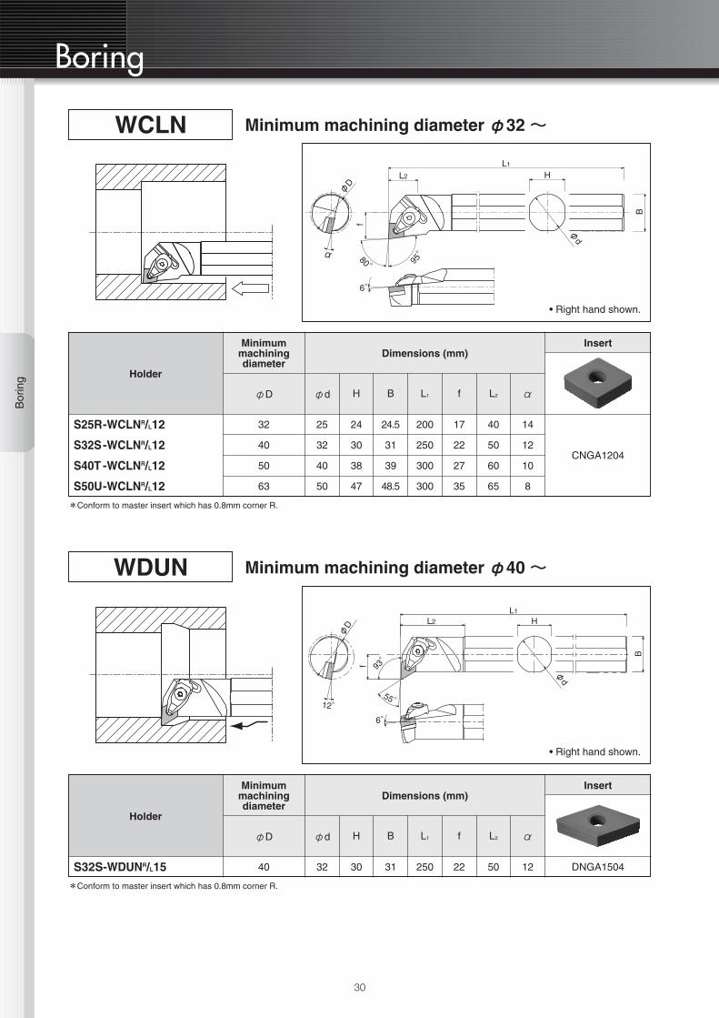
Holder
Dimensions (mm)
φd H B L1 f L2 αφD
25
32
40
50
24
30
38
47
24.5
31
39
48.5
200
250
300
300
17
22
27
35
40
50
60
65
14
12
10
8
32
40
50
63
Minimummachiningdiameter
Insert
CNGA1204
S25R-WCLNR/L12
S32S-WCLNR/L12
S40T -WCLNR/L12
S50U-WCLNR/L12
WCLN Minimum machining diameter φ32 ~
L2 HL1
B
φd
α
φD
f
95°
80°
6°
*Conform to master insert which has 0.8mm corner R.
• Right hand shown.
Holder
Dimensions (mm)
φd H B L1 f L2 αφD
32 30 31 250 22 50 1240
Minimummachiningdiameter
Insert
DNGA1504S32S-WDUNR/L15
WDUN Minimum machining diameter φ40 ~
HL2
L1
B
φd
12°
φD
f 93°
55°
6°
*Conform to master insert which has 0.8mm corner R.
• Right hand shown.
Bor
ing
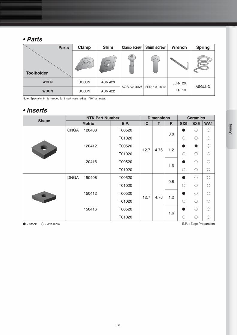
ShapeNTK Part Number Dimensions Ceramics
Metric E.P. IC T R SX9 SX5 WA1
CNGA 120408
120412
120416
T00520
T01020
T00520
T01020
T00520
T01020
12.7 4.76
0.8
1.2
1.6
●
○
●
○
●
○
○
○
●
○
○
○
○
○
○
○
○
○
DNGA 150408
150412
150416
T00520
T01020
T00520
T01020
T00520
T01020
12.7 4.76
0.8
1.2
1.6
●
○
●
○
●
○
○
○
○
○
○
○
○
○
○
○
○
○
31
Clamp
DC6CN
DC6DN
ACN 423
ADN 422AOS-6×30W FSS15-3.0×12
LLR-T20
LLR-T10ASGL6-D
Shim Clamp screw Shim screw Wrench SpringParts
Toolholder
WCLN
WDUN
• Parts
Note: Special shim is needed for insert nose radius 1/16" or larger.
• Inserts
●:Stock ○:Available E.P. : Edge Preparation

32

Holder Profiling & Grooving

Pro
filin
g
Profiling
34
CRSPC
AF
D
45°
B
B
• Right hand shown.
CRCP
F
C
A
BB
D
• Right hand shown.
• Toolholders
NTK Toolholder NO.Dimensions(INCH)
Shim
ARCGX23-0
ShimScrew
3-48x3/8B.H.C.S.
Clamp
R.H. CRR-2VL.H. CRL-2V
ClampScrew
1/4-20x1S.H.C.S
ARCGX35-06-32x1/2B.H.C.S.
CRN-3V#10-32x1/2
S.H.C.S
ARCGX45-010-32x5/8B.H.C.S.
CRN-4V1/4-20x3/4
S.H.C.S
Inserts
RCGX0607and
RPGX0607
RCGX0907and
RPGX0907
RCGX1207and
RPGX1207
A
1.001.251.501.001.251.501.001.251.50
B
1.001.251.501.001.251.501.001.251.50
C
6.006.008.006.006.008.006.006.008.00
D F
0.751.251.501.751.251.501.751.251.501.75
1.13
1.50
CRCPR/L16-2V-DCRCPR/L20-2V-DCRCPR/L24-2V-FCRCPR/L16-3V-DCRCPR/L20-3V-DCRCPR/L24-3V-FCRCPR/L16-4V-DCRCPR/L20-4V-DCRCPR/L24-4V-F
• Toolholders
NTK Toolholder NO.Dimensions(INCH)
Shim
ARCGX23-11
ShimScrew
3-48x3/8B.H.C.S.
Clamp
R.H. CRR-2V-GCL.H. CRL-2V-GC
ClampScrew
1/4-20x1S.H.C.S
ARCGX35-136-32x1/2B.H.C.S.
CRN-3V#10-32x1/2
S.H.C.S
ARCGX45-1510-32x5/8B.H.C.S.
CRN-4V1/4-20x3/4
S.H.C.S
Inserts
RCGX0607and
RPGX0607
RCGX0907and
RPGX0907
RCGX1207and
RPGX1207
A
1.001.251.501.001.251.501.001.251.50
B
1.001.251.501.001.251.501.001.251.50
C
6.006.008.006.006.008.006.006.008.00
D F
0.251.251.501.751.251.501.751.251.501.75
0.25
0.25
CRSPR/L16-2V-DCRSPR/L20-2V-DCRSPR/L24-2V-FCRSPR/L16-3V-DCRSPR/L20-3V-DCRSPR/L24-3V-FCRSPR/L16-4V-DCRSPR/L20-4V-DCRSPR/L24-4V-F
(INCH)
(INCH)
Pro
filin
g
35
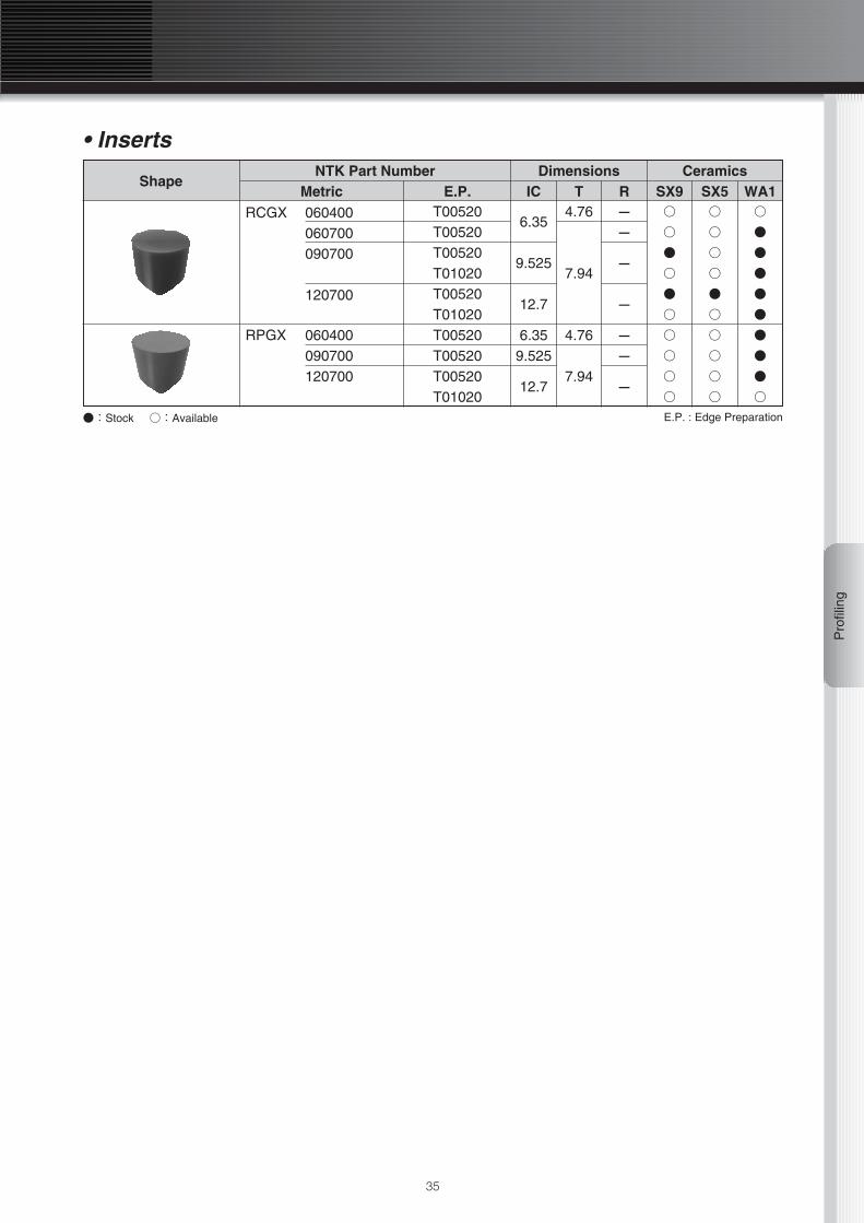
●:Stock ○:Available E.P. : Edge Preparation
ShapeNTK Part Number Dimensions Ceramics
Metric E.P. IC T R SX9 SX5 WA1
RPGX 060400090700120700
RCGX 060400060700090700
120700
T00520T00520T00520T01020
T00520T00520T00520T01020T00520T01020
6.359.525
6.35
7.94
-
9.525 -
12.7 -
12.7
4.76
7.94
4.76
- -
-
-
○
○
○
○
○
○
●
○
●
○
○
○
○
○
○
○
○
○
●
○
●
●
●
○
○
●
●
●
●
●
• Inserts

36
Gro
ovin
g
Grooving
BGV
Note: Shank comes with anvil screws - order anvil separately
L
FW
H
L2
L2
• Shank
• AnvilRight hand
Left hand
Dimensions
Dimensions
L2 (inch)
L2 (inch)
Insert
Insert
Clamp Screw
Clamp Screw
Clamp
Clamp
BGVR 043020
054520
074520
086020
106020
119020
BGVL 043020
054520
074520
086020
106020
119020
.375
.562
.562
.750
.750
1.125
.375
.562
.562
.750
.750
1.125
BGCR 04
BGCR 05
BGCR 07
BGCR 08
BGCR 10
BGCR 11
BGCL 04
BGCL 05
BGCL 07
BGCL 08
BGCL 10
BGCL 11
BRCS 2V
BRCS 2V
VGW 41254156
VGW 41564187
VGW 62186250
VGW 62506281
VGW 83128344
VGW 83448375
VGW 41254156
VGW 41564187
VGW 62186250
VGW 62506281
VGW 83128344
VGW 83448375
Shank
1.25 1.38 5.5 BAS 20
Dimensions (inch)Anvil Screw
H W LBS 20
Note: Anvil comes with clamp & clamp screw
・Right hand shown.Axial mounting
Radial mounting

37
Gro
ovin
g
ShapeNTK Part Number Dimensions Ceramics
Metric W R T L SX9 SX5 WA1VGK 8250-2
8312-R8312-28312-48375-28375-4
VGW 4125-R4125-14125-24156-R4156-14156-24187-R4187-14187-26250-R6250-16250-26250-36281-R6281-16281-26281-38312-R8312-18312-28312-38312-48344-R8344-18344-28344-38344-48375-R8375-18375-28375-38375-4
0.8FULL-R
0.81.60.81.6
FULL-R 0.40.8
FULL-R 0.40.8
FULL-R0.40.8
FULL-R 0.40.81.2
FULL-R 0.40.81.2
FULL-R 0.40.81.21.6
FULL-R 0.40.81.21.6
FULL-R 0.40.81.21.6
6.35
7.92
9.525
3.18
3.96
4.75
6.35
7.14
7.92
8.74
9.525
8.33
4.75
6.35
8.56
25.4
12.7
19.05
25.4
○
○
○
○
○
○
○
○
○
○
○
○
○
○
○
○
○
○
○
○
○
○
○
○
○
○
○
○
○
○
○
○
○
○
○
○
○
○
○
○
○
○
○
○
○
○
○
○
○
○
○
○
○
○
○
○
○
○
○
○
○
○
○
○
○
○
○
○
○
○
○
○
○
○
○
○
○
○
○
○
○
○
●
●
●
●
●
●
●
●
●
●
●
●
●
●
○
○
○
●
○
●
○
●
●
○
○
○
○
●
○
●
○
●
●:Stock ○:Available E.P. : Edge Preparation
L
W
r
r
90°
T
FULL RADIUS 11°
Standard Edge Preparation for WA1 is EX0001 which means 0.05mm or less honing only.Standard Edge Preparation for SX5 & SX9 are T00520 chamfer only.Standard Edge Preparations are not listed in this grooving inserts.

38
Holder Milling
Mill
ing
40
Milling
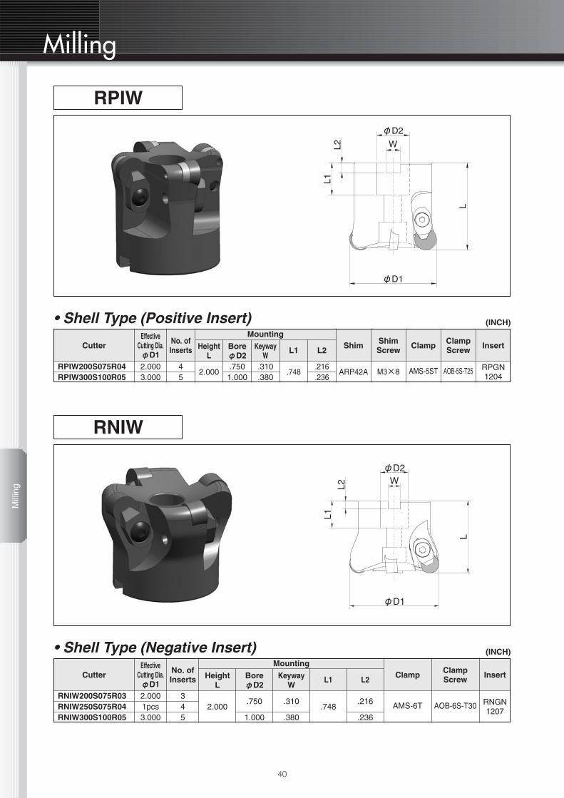
• Shell Type (Negative Insert)
• Shell Type (Positive Insert)
CutterEffective
Cutting Dia.φD1
No. ofInserts Height
L
Mounting
BoreφD2
KeywayW
L1 L2Shim Clamp Clamp
ScrewShimScrew Insert
RPGN1204
2.0003.000
45
2.000.750
1.000.310.380
ARP42A.216.236
.748 M3×8 AMS-5ST AOB-5S-T25RPIW200S075R04RPIW300S100R05
CutterEffective
Cutting Dia.φD1
No. ofInserts Height
L
Mounting
BoreφD2
KeywayW
L1 L2Clamp Clamp
Screw Insert
RNGN1207
2.0001pcs3.000
345
2.000.750
1.000
.310
.380.748
.216
.236AMS-6T AOB-6S-T30
RNIW200S075R03RNIW250S075R04RNIW300S100R05
RPIW
RNIW
(INCH)
(INCH)
L
φD1
φD2W
L1
L2
L
φD1
L1L2
φD2
W

Mill
ing
41
• End Mill Type (Positive Insert)
CutterEffective
Cutting Dia.φD1
No. ofInserts
ShankDiameterφD2
OverallLength
L
HeadLength
L2Clamp Clamp
Screw Insert
RPGN12041
1.5003
1.2501.500
4.0001.6401.830
AMT-5T AOB-5S-T25RPIW125E125R03RPIW150E150R03
RPIW
(INCH)
●:Stock ○:Available E.P. : Edge Preparation
ShapeNTK Part Number Dimensions Ceramics
Metric E.P. IC T R SX9 SX5 WA1
RNGN 120700 E002
T00520
T01020
T02020
12.7 7.94 -
○
●
○
○
○
●
●
○
○
●
●
○
RPGN 120400 T00520
T0102012.7 4.76 -
○
○
○
○
○
○
• Inserts
L
L2
φD
2
φD
1

42

Technical Information
44
Technical InformationT
echn
ical
Info
rmat
ion
600
500
400
300
200
100
0Light Interrupted InterruptedContinuous
Cut
ting
Spe
ed(
m/m
in)
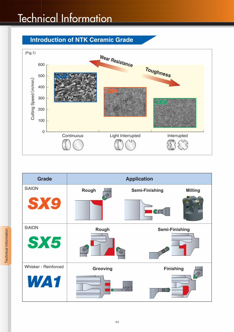
Toughness
Wear Resistance
WA1
SX9
SX5
WA1
SX9
SX5
Grade
SX9SiAlON
SX5SiAlON
WA1Whisker - Reinforced
Application
(Fig,1)
Rough Semi-Finishing Milling
Rough Semi-Finishing
Grooving Finishing
Introduction of NTK Ceramic Grade

45
Tec
hnic
al In
form
atio
n
■ Use strong Insert shapes.Maximize geometry for strength productivity
■ Use largest Nose RadiusMaximize insert nose radius for strength and longer tool life.Take into account that the larger the nose radius the greater the tool pressure.Typical application machining nickel-based alloys use RNG1207 insert for roughing andCNG1204 for finishing.
■ Minimise overhang Too much overhang may cause chatter orinsert breakage
■ No dwellingInserts wear out when rubbing the part instead of cutting.
■ CoolantWhen turning with SX9 ,SX5 ,WA1 ,ZM3 & QM3 a flood coolant condition should be used.In some cases where a high interruption is encountered it may be best to cut-off the coolant.No coolant should be used while milling with SX5 & SX9.
■ Edge preparations.Typical cutting tool applications machining nickel-based alloys require the insert cutting edgeto be sharp.Using slight T-land is effective to reducing notching.
■ Pre-ChamferingPre-chamferring the part reduces thepotential for insert chipping or breakingupon entry or exit point of work material.
STRENGTH INCREASES
Better!Better!
(Fig,2)
(Fig,3)
Selection for Successful use

46
500
400
300
200
100
00.1 0.2 0.3 0.4 0.5 0.6 0.70
Cut
ting
Spe
ed(
m/m
in)
Feed Rate(mm/rev)
Work MaterialHardnessInsert ShapeDepth of Cut(mm) Coolant
INCONEL 71835
RNGN 12072.0
WET
SX9 & SX5Recommended Area
Technical InformationT
echn
ical
Info
rmat
ion
蘆SX9 & SX5
500
400
300
200
100
00.1 0.2 0.3 0.4 0.5 0.6 0.70
Cut
ting
Spe
ed(
m/m
in)
Feed Rate(mm/rev)
Work MaterialHardnessInsert ShapeDepth of Cut(mm) Coolant
INCONEL 71835
RNGN 12072.0
WET
WA1Recommended Area
蘆WA1
(Fig,4)
(Fig,5)
Application Range For Nickel Based Alloys

A B C Cutting Speed (m/min)× × =Recommended
47
Tec
hnic
al In
form
atio
n
A B C Cutting Speed (m/min)× × =Recommended
Rough Turning ScaleRough no scale &
semi FinishGrooving Milling
Work MaterialRating
B1st 2nd 1st 2nd 1st 2nd 1st 2nd
Airesist
Astrology
Hastelloy C
Inco625
Inco713
Inco718
Inco738
Inco909
Inco925
Mar M247
Udimet720
Waspalloy
1.6 0.8 1.8 0.8 1.0 1.0 1.2 1.5 1.0 1.0 0.8 0.8
SX9
SX5
SX9
SX9
SX9
SX5
SX9
SX9
SX5
SX9
SX9
SX5
SX5
SX9
SX5
SX5
SX5
SX9
SX5
SX5
SX9
SX5
SX5
SX9
WA1
WA1
WA1
WA1
WA1
WA1
WA1
WA1
WA1
WA1
WA1
WA1
SX9
SX9
SX9
SX9
SX9
SX9
SX9
SX9
SX9
SX9
SX9
SX9
WA1
WA1
WA1
WA1
WA1
WA1
WA1
WA1
WA1
WA1
WA1
WA1
SX5
SX5
SX5
SX5
SX5
SX5
SX5
SX5
SX5
SX5
SX5
SX5
SX9
SX9
SX9
SX9
SX9
SX9
SX9
SX9
SX9
SX9
SX9
SX9
SX5
SX5
SX5
SX5
SX5
SX5
SX5
SX5
SX5
SX5
SX5
SX5
Machinability rating and recommended insert grades for machining various High temperature alloys are shown in Table1.
Table1
Table2
Find recommended insert grade from above Table 1 in consideration of your work material &application. Contact your local NTK representative, if more information is needed.
1) Find cutting speeds "A" shown in "Grade Selection" on page 7.2) Find machinability rating "B" of your work material from above Table 1.3) Find machinability rating "C" of your work hardness from Table 2 below.
HRC (Hardness) < 30 30 35 40 45
C 1.3 1.15 1 0.85 0.7
Recommended Grades for High Temperature Alloys
How To Find Recommended Insert Grade
How To Find Recommended Cutting Speed
Recommendation for Hardness
Recommended Cutting Speed

48
Technical InformationT
echn
ical
Info
rmat
ion
The usual failure mode for ceramic inserts cutting Nickel-Based Alloys is "Notching".Notch wear can be reduced by re-programing. Tool life should improve with by following these guidelines.The following information should help to minimize this problem.
1 Depth of Cut
蘆GUIDELINES FOR SUCCESSFUL USE OF SX9Depth of Cut Notching. This mode of insert failure istypical when machininng nickel based alloys. It must becontrolled to prevent a catastrophic failure of theinsert's cutting edge. The following information shouldhelp to minimize this probrem.
Depth of Cut. Prime consideration should be given tothe effect of depth of cut upon insert tool life.There is a direct relationship between the insert radiussize and the maximum depth of cut which should betaken. See the chart below for recommendations.
(Fig,6)
2 Lead AngleLead Angles. When cutting nickel based alloys consideration shouldbe given to useing the largest lead angle possible. Whenuseing large lead angles,the cutting forces are spreadover a larger surface area of the insert. This will alsoimprove tool life and surface finish while reducing notch-ing. As the lead angle increases the chip will flow moreeasily.
Feeds.Utillize the superior strength characteristic of SX9 siliconnitride ceramic. If excessive wear is encountered whilemachining high nickel based materials, increase thefeed rate thus minimizing the cutting time.
-5
-5
00
15
15
45
45
(Fig,7)
蘆Typical Insert Wear Pattern Showingthe Effect of Various Lead AngleChanges and the Resulting increase ofDepth of Cut Notching.
Round Insert Maximum D. of C. *Insert Radius Maximum D. of C.
6.359.52512.725.4
*Optimum D. of C. is 5 -15% of the Insert diameter based on 0º lead angle
1.52.33.26.4
0.81.21.62.4
0.20.30.40.6
Recommended Depth of Cut Range
How To reduce Notch Wear
49
Tec
hnic
al In
form
atio
n
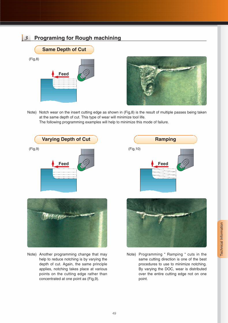
3 Programing for Rough machining
Note) Notch wear on the insert cutting edge as shown in (Fig,8) is the result of multiple passes being takenat the same depth of cut. This type of wear will minimize tool life.The following programming examples will help to minimize this mode of failure.
Note) Another programming change that mayhelp to reduce notching is by varying thedepth of cut. Again, the same principleapplies, notching takes place at variouspoints on the cutting edge rather thanconcentrated at one point as (Fig,9).
Feed
(Fig,8)
Feed
(Fig,9)
Same Depth of Cut
Varying Depth of Cut
Note) Programming " Ramping " cuts in thesame cutting direction is one of the bestprocedures to use to minimize notching.By varying the DOC, wear is distributedover the entire cutting edge not on onepoint.
Feed
(Fig,10)
Ramping

50
Technical InformationT
echn
ical
Info
rmat
ion
4 Programing for Grooving
45
(Fig,11)
L R
L R
45
(Fig,12)
L R
L R
Note) Another option in removing a pocket ofmaterial would be shown in (Fig,12). Thegrooving insert is plunged down both out-side walls thus maintaining a good finish.The remaining material can be removed byusing a stronger insert shape such as aRCGX style.
Note) When machining a grooved area with multi-ple passes during the last remaining plungethe insert radius engages a potentially workhardened area. This programming proce-dure sets up the potential of corner radiuschipping (Ref. L) or notching. The proceduredescribed below (Fig,11) would be a betterprogramming alternative.

51
Tec
hnic
al In
form
atio
n
5 Programing for Finish machining
(Fig,14)
Note) The correct procedure is to take more material off during the previous roughing application.Then remove the amount of stock suitable for the nose radius of the insert by stayingbelow the 45°mark of the corner radius.This will minimize notching and allow a cut frow both directions.
INSERT RADIUS DEPTH OF CUT
(mm) (Inch) (mm) (Inch)
0.4
0.8
1.2
1.6
2.0
2.4
3.2
0.0157
0.0315
0.0472
0.0630
0.0787
0.0945
0.1260
0.12
0.23
0.35
0.47
0.59
0.70
0.94
0.0047
0.0091
0.0138
0.0185
0.0232
0.0276
0.0370
α=45º
45
Depth of Cut
Better
Depth of Cut
α=45º
(Fig,13)
52
Technical InformationT
echn
ical
Info
rmat
ion
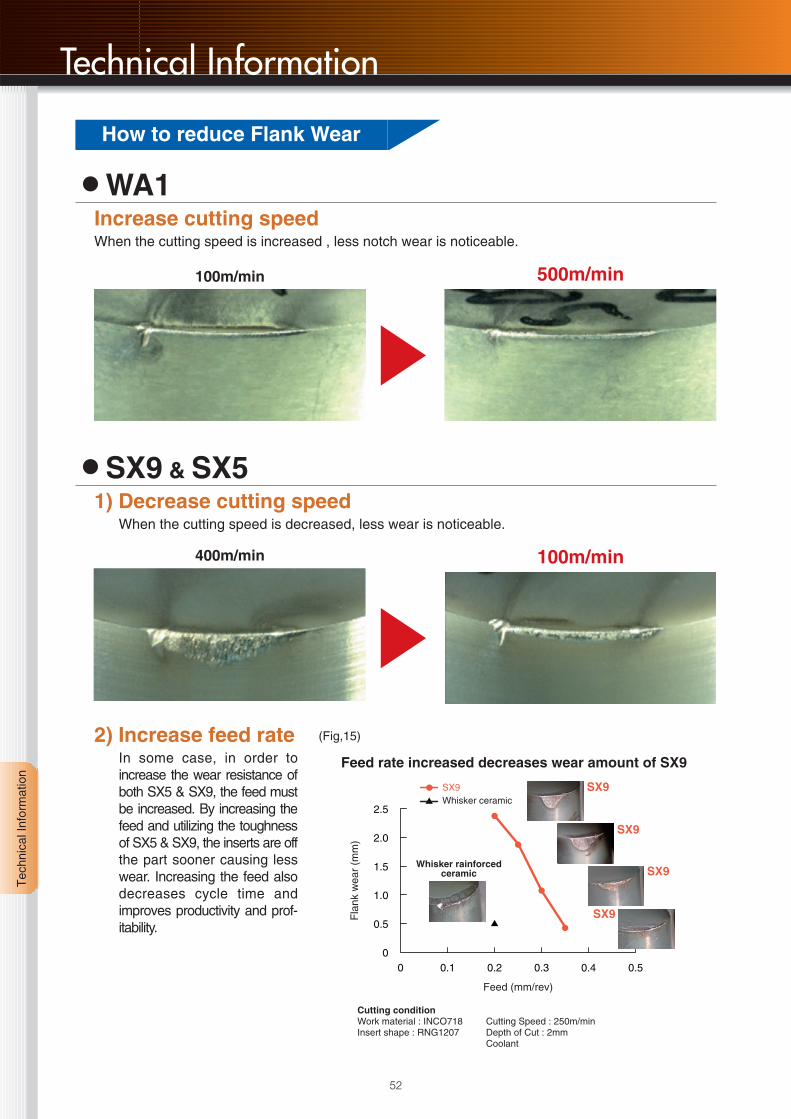
蘆WA1Increase cutting speedWhen the cutting speed is increased , less notch wear is noticeable.
500m/min100m/min
蘆SX9 & SX51) Decrease cutting speed
When the cutting speed is decreased, less wear is noticeable.
2) Increase feed rateIn some case, in order toincrease the wear resistance ofboth SX5 & SX9, the feed mustbe increased. By increasing thefeed and utilizing the toughnessof SX5 & SX9, the inserts are offthe part sooner causing lesswear. Increasing the feed alsodecreases cycle time andimproves productivity and prof-itability.
100m/min400m/min
0 0.1 0.2 0.3 0.4 0.5
2.5
2.0
1.5
1.0
0.5
0
Whisker rainforcedceramic
Feed (mm/rev)
Fla
nk w
ear
(mm
)
Cutting conditionWork material : INCO718Insert shape : RNG1207
Cutting Speed : 250m/minDepth of Cut : 2mmCoolant
SX9Whisker ceramic
SX9
SX9
SX9
SX9
Feed rate increased decreases wear amount of SX9
(Fig,15)
How to reduce Flank Wear

53
Tec
hnic
al In
form
atio
n
6 Problem and Solution
Chatter problem is often caused by too much cutting pressure when machining nickel-based alloys in especially profiling cut or grooving where over hang of holder needed, cut-ting thin-walled parts or no rigidity machine, and it causes excessive insert wear or insertbreakage.
Increase speeds and decrease feeds蘆Use WA1 with higher speed instead of SX5 or SX9
蘆Use smaller I.C round insert, or smaller nose radius
蘆Take insert shape with acute angle possible
蘆Use positive insert
蘆Reduce lead angle
蘆Reduce edge preparation or use sharp edge
蘆Minimize overhang
蘆Holder made from heavy metals is effective
Flaking
Breakage
Chatter
Solution
Solution
Decrease Feed rateUse the slight bigger edge preparation
AngleWidth Width
STRENGTH INCREASES
Decrease Cutting speed and feedUse more Strength insert shape
If Material hardness is not known then more timeis needed in the testing procedure trying to findthe optimum speed and feed range. As the mate-rial hardness increases speed should decrease.

Tec
hnic
al In
form
atio
n
54
Technical Information
Ni-based Heat Resistant AlloysMaterial Specifications Cross-Reference List -Aerospace Material Designation
Materialcondition
Ni-based alloys
Annealed or
solution treated
Haynes 80A
Haynes 75
Haynes 263
Haynes 600
Haynes 625
Haynes X-750
Haynes 718
Inconel 781
Nimocast PE10
Nimocast PD16
Nimocast PK24
Nimocast 842
Nimocast 713
Nimonic 95
Nimonic 242
Nimonic PE13
Nimonic PK25
Nimonic PK31
Refractaloy 26
Rene 63
Rene 77
Rene 80
Rene 95
Rene 100
Rene 125
TRW 1800
TRW V1 A
Udimet 630
Udimel 700
Udimet 710
Hastalloy B*
Hastalloy C*
Hastalloy N*
Hastalloy W*
Hastalloy X*
lncoloy 804*
lncoloy 825*
Inconel 600*
Inconel 601*
lnconel 604*
Inconel 625*
Monel 400*
Monel R-405*
Nimonic 75*
—
—
—
—
—
—
—
—
—
—
—
—
—
—
—
—
—
—
—
—
—
—
—
—
—
—
—
—
—
—
140
200
—
—
160
—
180
170
150
180
180
110
110
170
—
—
—
—
—
—
—
—
—
—
—
—
—
—
—
—
—
—
—
—
—
—
—
—
—
—
—
—
—
—
—
—
—
—
—
—
—
—
—
—
—
—
—
—
70.9
73.7
51.4
75.9
61.4
74.9
53.5
70.0
56.4
43.8
61.1
57.7
72.6
49.9
58.0
49.0
49.9
53.8
38.0
54.4
57.6
61.0
64.5
60.6
60.0
70.0
70.5
51.0
54.6
55.0
64.3
54.1
72.2
62.7
47.1
41.0
42.0
75.0
60.0
74.4
61.0
65.0
66.0
75.0
20.0
20.0
20.0
16.0
21.0
16.0
18.0
16.0
20.0
16.5
9.5
22.0
13.4
19.5
21.5
21.8
19.0
20.0
19.0
14.0
15.0
14.0
14.0
10.0
8.9
13.0
6.0
17.0
15.0
18.0
0.6
16.0
7.0
5.0
22.0
29.5
21.0
15.5
23.0
15.8
21.5
—
—
19.5
2.0
—
20.0
—
—
—
—
—
—
—
15.0
10.0
—
—
10.0
1.5
19.5
14.0
20.0
15.0
15.0
9.5
8.0
15.0
10.0
—
7.5
—
17.5
15.0
1.25
1.25
0.25
1.25
1.5
—
—
—
—
—
—
—
—
—
3.0
5.0
—
8.0
5.0
7.0
19.0
8.0
—
34.0
—
—
—
5.0
—
18.5
—
—
16.0
0.5
0.4
—
—
—
—
—
—
17.5
—
0.5
5.5
5.75
3.0
5.5
18.5
26.0
30.0
8.0
14.0
7.2
2.5
1.5
1.2
4.0
—
—
6.0
—
9.0
—
3.0
—
6.0
3.3
3.0
10.0
4.5
—
10.5
9.0
4.0
4.5
3.2
6.0
4.2
4.0
3.5
3.0
2.0
—
2.0
3.0
—
1.5
28.0
17.0
16.5
24.5
9.0
—
3.0
—
—
—
9.0
—
—
—
0.1
0.12
0.06
0.08
0.1
0.08
0.08
0.07
—
0.06
0.17
0.3
0.12
0.11
—
0.1
0.08
—
0.03
0.05
0.17
0.15
0.15
0.18
0.1
0.1
0.13
0.04
0.1
0.07
0.1
0.07
0.06
0.06
0.1
0.1
0.04
0.05
0.05
0.04
0.04
0.12
0.15
0.12
—
—
—
—
—
—
—
2.25
—
—
—
—
—
—
—
0.5
0.8
—
0.8
0.1
0.1
—
—
—
—
—
—
—
—
—
0.8
0.8
0.4
0.5
0.6
1.0
—
—
—
0.2
0.5
1.0
1.0
—
—
—
—
—
—
—
—
0.15
—
—
—
—
—
1.0
—
0.5
0.8
—
1.0
0.2
0.1
—
—
—
—
—
—
—
—
—
0.7
0.7
0.25
0.5
0.6
0.75
—
—
—
0.2
0.5
—
—
—
1.5
0.25
1.0
—
—
0.8
0.5
0.1
—
1.2
5.5
—
6.2
2.0
—
—
2.9
0.4
0.2
3.8
4.3
—
—
5.5
4.7
6.0
5.4
0.6
4.4
2.5
—
—
0.5
—
—
0.25
—
—
1.4
—
0.4
—
—
—
2.5
0.4
1.5
—
—
0.25
0.9
3.0
—
1.2
4.7
—
1.0
3.5
—
—
2.9
2.3
2.75
2.5
3.3
4.0
2.5
4.7
2.5
0.06
1.0
1.1
3.4
5.0
—
—
—
—
—
0.6
1.0
—
—
—
0.4
—
—
0.4
—
0.5
—
—
3.5
1.0
5.0
0.2
9.0
—
1.0
—
2.3
—
—
0.6
—
5.0
—
3.5
—
8.0
3.5
—
7.0
10.5
6.3
4.1
—
1.5
—
4.0
0.21
—
0.6
0.5
2.0
—
—
0.1
3.6
32.0
31.06
—
Commercialdesignation
HardnessBrinell HB
Ann. Aged
Nominal compositionApproximate content in %
Ni Cr Co Fe Mo C Mn Si Al Ti Others
* These alloys cannot be hardened by aging process.

Tec
hnic
al In
form
atio
n
55
USA
SAE
—
—
—
—
—
—
—
—
—
—
—
5391A
—
—
—
5536E
5751A
—
—
—
—
—
—
—
—
—
—
—
—
—
5396A
5388C
5771
—
5390A
—
—
5540
—
—
—
4544
4674
—
AMS
—
—
—
—
—
5542
—
—
—
5397
—
—
—
—
—
5754E
5753
—
—
—
—
—
—
—
—
—
—
—
—
—
5396
5388
5607
5786
5390
—
—
5580
5715
—
5666
4574
7234
—
UK
BS
—
—
—
—
—
—
—
—
—
HC204
3146
HC203
—
—
—
HR6,204
—
—
—
—
—
—
—
—
—
—
—
—
—
—
—
—
—
—
—
—
3072-76
3072-76
—
—
—
3072-76
—
HR5,203-4
France
AFNOR
—
—
—
—
—
NC15TNbA
—
—
—
NK15CAT
—
NC13AD
—
—
—
NC22FeD
NKOD20ATU
—
Z6NKCDT38
—
—
—
NC14K8
—
—
—
—
—
NCKD20AT
NC18TDA
ND37FeV
—
—
—
NC22FeD
—
NC21FeDU
NC15Fe
—
—
NC22FeDNB
NU30
—
NC20T
Germany
Werkst.-Nr
—
—
—
—
—
—
—
—
—
LW2.4674
—
2.4670
—
—
—
2.4665
2.4666
—
—
—
—
—
—
—
—
—
—
2.4668
2.4636
—
2.4800
2.4602
—
—
2.4603
—
2.4858
2.4816
2.4851
—
2.4856
2.4360
—
2.4630
DIN1706
—
—
—
—
—
—
—
—
NiFe33Cr17Mo
—
—
S-NiCr13AI6MoNb
—
—
—
NiCr22Fe18Mo
NiCr18CoMo
—
—
—
—
—
—
NiCo15Cr10MoAITi
—
—
NiTa9Co8W6CrAI
NiCr19NbMo
NiCo15CrMoAlTi
—
S-NiMo30
NiCr17Mo17FeW
—
—
—
—
NiCr21Mo
NiCr15Fe
NiCr23Fe
—
NiCr22Mo9Nb
NiCu30Fe
—
NiCr20Ti
Others
—
—
—
—
—
—
—
—
—
—
—
—
—
—
—
—
—
—
—
—
—
—
—
—
—
—
—
—
—
—
N10001
N10002
N10003
N10004
N06002
—
N08825
N06600
N06601
—
N06625
N04400
N04405
—
Customerdesignation

Tec
hnic
al In
form
atio
n
56
Technical Information
Ni-based Heat Resistant AlloysMaterial Specifications Cross-Reference List -Aerospace Material Designation
Materialcondition
Aged or solution
treated and aged
Cast or cast
and aged
Astroloy*
Hastelloy R235*
lncoloy 901*
lncoloy 903*
Inconel 700*
lnconel 702*
InconeI 706*
lnconel 713*
Inconel 718*
Inconel 722*
Inconel X-750*
Inconel 751*
Jethete M-252*
MAR-M 246*
MAR-M 421*
MAR-M 432*
Monel K-500*
Nimocast 80*
Nimocast 90*
Nimonic 80A*
Nimonic 90*
Nimonic 105*
Nimonic 115*
Nimonic 901*
Nimonic 263/C263*
Nimonic PE16*
Nimonic PK33*
R-235*
Rene 41
Udimet 500*
Udimet 718*
Waspaloy*
GMR 235*
GMR 235D
lN-100*
Jessop G39*
Jessop G64*
Jessop G81*
MAR-M 200*
—
—
180
—
—
—
—
—
180
—
—
—
—
—
—
—
120
—
—
—
—
—
—
—
—
—
—
—
—
—
180
—
—
—
—
130
220
—
—
—
—
300
380
350
—
—
—
380
380
390
—
320
270
—
—
290
—
—
350
346
320
350
350
275
250
350
—
—
—
380
—
—
—
—
—
—
300
—
56.9
61.0
44.3
39.0
46.0
79.6
42.0
75.0
52.5
74.8
73.0
70.0
55.3
59.5
62.3
52.3
64.0
69.9
52.9
75.0
59.0
53.0
59.0
44.0
51.5
43.5
55.9
63.3
53.1
51.7
52.5
56.9
63.3
63.0
61.6
67.5
60.7
79.3
69.4
15.0
15.0
12.5
—
15.0
15.6
16.0
12.5
19.0
15.0
15.5
15.5
20.0
9.0
15.5
15.5
—
20.0
20.0
19.5
19.5
15.0
14.2
12.5
20.2
16.5
18.0
15.0
19.0
19.0
18.0
19.8
15.5
15.5
10.0
19.5
11.0
20.0
9.0
15.0
2.5
—
15.0
23.5
—
—
—
—
—
—
—
10.0
10.0
10.0
20.0
—
2.0
18.0
—
16.5
20.0
13.2
—
20.0
—
14.0
1.2
11.0
19.0
—
13.5
—
—
15.0
—
—
13.0
10.0
—
10.0
34.0
41.0
0.7
0.35
40.0
—
19.0
6.5
7.0
7.0
—
0.2
—
—
1.0
5.0
5.0
—
—
—
—
35.0
—
34.0
0.5
10.0
1.8
—
18.0
0.8
10.0
4.5
—
5.0
2.0
—
—
5.25
5.5
6.0
—
3.75
—
—
4.2
3.0
—
—
—
10.0
2.5
1.7
—
—
—
—
—
—
5.0
4.0
5.7
6.0
3.3
7.0
5.5
10.0
4.0
3.0
4.45
5.2
5.0
3.0
3.0
3.0
—
—
0.06
0.15
0.05
0.02
0.12
0.04
0.03
0.12
0.04
0.04
0.04
0.1
0.15
0.15
0.15
0.15
0.13
0.1
0.1
0.08
0.08
0.12
0.16
0.04
0.06
0.06
0.05
0.12
0.09
0.1
0.05
0.07
0.15
0.15
0.18
0.5
0.15
0.05
0.15
—
0.25
0.24
—
0.10.0
0.05
0.2
—
0.35
0.55
0.35
1.0
0.5
—
—
—
0.8
—
—
—
—
—
—
—
—
—
0.25
0.1
0.3
0.1
—
0.1
0.25
0.1
1.2
—
—
—
—
—
0.6
0.12
—
0.3
0.2
0.3
—
0.35
0.2
0.35
0.5
0.5
—
—
—
—
—
—
—
—
—
—
—
—
—
0.25
0.3
0.3
0.1
—
0.1
0.6
0.3
0.5
—
—
—
—
4.0
3.0
0.15
0.7
3.0
3.0
0.4
6.1
0.9
0.6
0.7
1.5
1.0
5.5
4.3
2.8
2.8
1.0
1.5
1.4
1.5
4.7
5.0
0.3
0.5
1.2
2.1
2.0
1.5
3.0
0.6
1.4
3.0
3.5
5.5
—
6.0
1.3
5.0
3.5
2.0
2.7
1.4
2.2
0.7
1.75
0.8
0.9
2.4
2.5
2.6
2.6
1.5
1.75
4.3
0.6
2.0
2.5
2.4
2.5
1.2
4.0
2.9
2.0
1.2
2.2
2.5
3.1
3.0
0.1
3.0
2.0
2.5
4.75
—
—
2.3
2.0
0.05
—
0.15
3.0
—
—
—
—
0.1
—
—
0.5
—
11.5
5.3
5.0
30.0
—
—
—
—
—
—
—
—
—
—
—
—
—
5.2
—
0.06
0.05
—
4.5
4.0
—
13.5
Commercialdesignation
HardnessBrinell HB
Ann. Aged
Nominal compositionApproximate content in %
Ni Cr Co Fe Mo C Mn Si Al Ti Others
* These alloys can be hardened by an aging process.** These alloys cannot be hardened by an aging process.
Tec
hnic
al In
form
atio
n
57
USA
SAE
—
—
—
—
—
—
—
—
5383
—
5542G
—
—
—
—
—
4676
—
—
—
—
—
—
5660C
—
—
—
—
—
—
5383
—
—
—
—
—
—
—
—
AMS
—
—
5660
—
—
5550
5702
5391
5589
5541
5582
—
5551
—
—
—
—
—
—
—
—
—
—
5661A
—
—
—
—
5399
5751
5589
5544
—
—
5397
—
—
—
—
UK
BS
—
—
—
—
—
—
—
3146-3
HR8
—
—
—
—
—
—
—
3072-76
3146
—
Hr401,601
Hr2,202
HR3
HR4
—
HR10
HR207
—
—
—
—
HR8
—
—
—
—
—
—
—
—
France
AFNOR
—
—
ZSNCDT42
—
NK27CADT
—
—
NC12AD
NC19FeNB
NC16FeTi
NC16FeTNb
—
—
—
—
—
—
—
—
NC20TA
Nc20ATV
NCKD20ATV
NCK15ATD
ZSNCDT42
NCK20D
NW11AC
NC19KDUV
—
NC19KDT
NCK19DAT
NC19FeN
NC20K14
—
—
—
—
—
—
—
Germany
Werkst.-Nr
—
—
LW2.4662
—
—
—
—
LW2.4670
LW24668
—
2.4669
—
2.4916
2.4675
—
—
2.4375
—
—
2.4631
2.4632
2.4634
2.4636
2.4662
2.4650
—
—
—
2.4973
2.4983
LW2.4668
LW2.4668
—
—
LW2.4674
—
—
—
—
DIN1706
—
—
NiFe35Cr14MoTi
—
NiCo29Cr15MoAITi
—
—
S-NiCr13AI6MoNb
NiCr19Fe19NbMo
NiCr16FeTi
NiCr16FeTi
—
S-NiCr19Co
NiCo10W10Cr9AITi
NiCR16Co10WAlTi
NiCo20Cr16WAITi
NiCu30AI
—
—
NiCr20TiAk
NiCr20Co18Ti
NiCo20C15MoAITi
NiCo15Cr15MoAITi
NiCr15MoTi
NiCr15Co19MoTi
NiFe33Cr17Mo
NiCr20Co16MoTi
—
NiCr19Co11MoTi
NiCr18Co18MoTi
NiCr19Fe19NbMo
NiCr19Fe19NbMo
—
NiCr16MoAl
NiCo15Cr10MoAITi
NiCr20MoW
NiCr11AIWNb
NiCr20Co18Ti
NiW13Co10Cr9AITi
Others
—
—
N09901
—
—
N07702
N09707
—
N07713
N07722
N07750
N07751
N07252
—
—
—
N05500
—
—
N07080
N07090
—
—
—
—
—
—
—
N07041
N07500
N07718
N07001
AISI:686
—
N13100
—
—
—
—
Customerdesignation

Tec
hnic
al In
form
atio
n
58
Technical Information
Co-based Heat Resistant AlloysMaterial Specifications Cross-Reference List -Aerospace Material Designation
Materialcondition
Co-based alloys
Annealed or
solution treated
In aged
condition
Air Resist 13
Air Resist 213
Altemp S 816
FSX 414
Haynes 36
Haynes 151
HS 25
HS 30
HS 31
HS 36
Jessop 832
Jessop 834
Jessop 865
Jessop 875
Jessop 887
Jetalloy 209
L-251
L-605
M 203
M 204
M 205
MAR-M 302
MAR-M 322
MAR-M 509
MAR-M 905
MAR-M 918
Refractaloy 70
V-36
Wl-52
Jessop X-40
Jessop X-45
Jessop X-50
Jessop X-63
J 1650
Haynes 25*
Haynes 188*
HS 6*
HS 21*
J1570*
—
—
—
—
—
—
—
—
—
—
—
—
1.0
—
20.0
10.0
10.0
—
10.0
16.0
10.0
10.0
12.0
12.0
10.5
—
10.0
10.0
10.0
10.0
25.0
25.0
25.0
—
—
10.0
20.0
20.0
20.0
20.0
0.5
10.5
10.5
20.5
10.0
27.0
10.0
22.0
2.5
3.0
28.0
—
19.0
20.0
29.0
18.5
20.0
20.0
24.0
25.0
18.0
19.0
19.0
25.5
21.0
20.0
20.0
19.0
20.0
20.0
18.0
18.0
21.5
21.5
23.0
20.0
20.0
21.0
25.0
21.0
25.5
25.5
25.5
25.0
19.0
20.0
22.0
28.0
27.0
19.0
79.6
65.8
47.6
52.8
52.8
65.6
48.4
51.4
53.8
53.1
44.0
42.0
53.0
66.0
50.0
52.0
56.0
51.0
38.0
42.0
40.0
57.0
60.0
55.0
55.0
52.0
46.0
43.2
62.6
53.0
54.7
40.3
57.6
38.0
49.0
38.0
60.5
62.6
39.0
2.5
—
—
1.0
2.0
—
3.0
1.0
1.5
2.0
17.0
20.0
2.0
—
3.0
1.0
1.0
1.6
1.6
1.6
1.6
0.75
0.75
—
—
0.4
0.5
2.4
2.0
1.5
2.0
4.0
1.0
—
3.0
2.5
3.0
2.0
2.0
—
—
4.0
—
—
—
—
6.0
—
—
2.0
2.0
—
—
—
—
—
—
—
—
—
—
—
—
—
—
8.0
4.0
—
—
—
—
6.0
—
—
—
—
5.0
—
11.0
4.7
4.0
7.0
14.5
12.8
15.0
—
8.0
15.0
—
—
7.5
11.0
15.0
15.0
14.0
15.0
12.0
12.0
12.0
10.0
9.0
7.0
—
—
4.0
2.0
11.0
7.5
7.0
12.0
—
12.0
15.0
14.0
5.0
—
7.0
—
—
—
—
1.2
0.5
1.5
0.6
0.6
1.5
0.8
—
0.6
—
0.5
—
—
1.5
0.8
—
—
0.1
0.1
0.05
—
0.1
—
0.6
0.25
0.75
—
—
—
—
1.5
1.0
—
0.6
—
—
—
—
0.6
0.5
2.0
0.6
0.8
—
0.3
—
0.6
—
1.5
—
—
0.6
1.0
—
—
0.2
0.1
0.05
—
0.1
—
0.5
0.25
0.75
—
—
—
—
0.5
0.4
—
0.6
—
3.5
3.5
—
—
—
—
—
—
—
—
—
—
—
—
—
—
—
—
0.7
—
2.7
—
—
—
—
—
—
—
—
—
—
—
—
—
—
—
—
—
—
—
—
—
—
—
0.15
—
—
—
—
—
—
—
—
—
2.0
—
—
2.0
—
—
—
0.75
0.2
0.5
0.5
—
—
—
—
—
—
—
—
—
—
—
—
—
4.12
6.68
0.4
0.25
0.4
0.47
0.1
0.4
0.4
0.4
3.5
6.5
0.45
2.45
0.1
0.02
0.4
0.1
1.67
1.27
1.67
10.0
7.7
4.6
7.65
7.65
0.08
2.29
2.45
0.5
0.25
0.75
0.45
0.2
0.1
0.1
1.0
0.25
—
Commercialdesignation
HardnessBrinell HB
Ann. Aged
Nominal compositionApproximate content in %
Ni Cr Co Fe Mo W Mn Si Al Ti Others
* These alloys can be hardened by an aging process.** These alloys cannot be hardened by an aging process.

Tec
hnic
al In
form
atio
n
59
USA
SAE
—
—
—
—
—
—
5380
5382
—
—
—
—
—
—
—
—
—
—
—
—
—
—
—
—
—
—
—
—
—
—
—
—
—
5537C
—
—
—
—
AMS
—
—
(5534)
—
—
—
5759
—
—
—
—
—
—
—
—
—
—
5759
—
—
—
—
—
—
—
—
—
—
—
5382
—
—
—
—
5759
5772
5373
5385
—
UK
BS
—
—
—
—
—
—
—
—
3146
—
—
—
—
—
—
—
—
—
—
—
—
—
—
3146-3
—
—
—
—
—
3156-2
—
—
—
—
—
—
—
3531
—
France
AFNOR
—
—
—
—
—
—
KC20WN
—
—
—
—
—
—
—
—
—
—
—
—
—
—
—
—
—
—
—
—
—
—
—
—
—
—
—
KC20WN
KC22WN
—
—
—
Germany
Werkst.-Nr
—
—
LW2.4989
—
—
—
LW2.4964
—
LW2.4670
—
—
—
—
—
—
—
—
2.4964
—
—
—
—
—
—
—
—
—
—
—
LW2.4670
—
—
—
—
LW2.4964
—
—
—
—
DIN1706
—
—
CoCr20Ni20W
—
CoCr19W14NiB
CoCr20W13
CoCr20W15Ni
CoCr25NiW
CoCr25NiW
CoCr19W14NiB
CoCr19Fe16NiMoVNb
CoCr19Fe20NiMoVNb
CoCr25Niw
CoCr21W11Nb
CoCr20W15Ni
—
—
CoCr20W15Ni
—
—
—
CoCrW10TaZrB
CoCr22W9TaZrNb
CoCr24Ni10WTaZrB
—
CoCr20Ni20Ta
—
CoCr25NiMoWNb
CoCr12MoW
CoCr25NiW
—
—
—
—
CoCr20W15Ni
CoCr22W14Ni
—
CoCr29Mo
—
Others
—
—
—
—
—
—
—
R30030
R30031
—
—
—
—
—
—
—
—
R30605
—
—
—
—
—
—
—
—
—
—
—
—
—
—
—
—
—
—
R30006
R30021
—
Customerdesignation

60
Index

Inde
x
62
Index
• Inserts • Toolholders, Mills, PartsItem Number Description Page
CNGA
CNGG-ZP
CNGN
CNMG-Z5
DNGA
DNGG-ZP
DNGN
DNMG-G
DNMG-Z5
RCGN
RCGX
RNGN
RPGN
RPGX
SNGA
SNGN
SNMG-Z5
TNGA
TNGN
TNGG-C
TNGG-DA
TNGG-LU2
TNGG-RU2
TNGG-ZP
TNMG-Z5
TPGN
VGK
VGW
VNGA
VNGG-ZP
VNMG-AM1
WNGA
WNGG-ZP
WNMG-Z5
Ceramic
Micrograin Carbide
Ceramic
Micrograin Carbide
Ceramic
Ceramic
Ceramic
Micrograin Carbide
Micrograin Carbide
Ceramic
Ceramic
Ceramic
Ceramic
Ceramic
Ceramic
Ceramic
Micrograin Carbide
Ceramic
Ceramic
Micrograin Carbide
Micrograin Carbide
Micrograin Carbide
Micrograin Carbide
Micrograin Carbide
Micrograin Carbide
Ceramic
Ceramic
Ceramic
Ceramic
Micrograin Carbide
Micrograin Carbide
Ceramic
Micrograin Carbide
Micrograin Carbide
14, 29, 31
18
14
18
14, 29, 31
18
14
18
18
22
14, 22, 35
15, 23, 29, 41
15, 41
15, 22, 35
15
15
18
16
16
18
18
18
18
19
19
16
17
17, 36, 37
16, 29
19
19
16
19
19
Item Number Description Page
2x8AW
2.5x8AW
ACN
ADN
AMS
AMT
AOB
AOS
ARCGX
ARN
ARP42A
ASGL6-D
AVN
BAS20
BGCL
BGCR
BGVL
BGVR
BRCS 2V
BS
BS0520
BS0625
BS0829W
BS0835W
CC08M
CC08MS
CRCPL
CRCPR
CRDCN
CRDNN
CRGNL
CRGNR
CRL
CRN
CRR
CRSPL
CRSPR
DC6CN
DC6DN
DC6VN
FSS
HARCGN
Spring Pin
Spring Pin
Shim
Shim
Clamp
Clamp
Clamp Screw
Clamp Screw
Shim
Shim
Shim
Spring
Shim
Anvil Screw
Clamp
Clamp
Tool Holder
Tool Holder
Clamp Screw
Tool Holder
Clamping Screw
Clamping Screw
Clamp Screw
Clamp Screw
Clamp
Clamp
Tool Holder
Tool Holder
Tool Holder
Tool Holder
Tool Holder
Tool Holder
Clamp
Clamp
Clamp
Tool Holder
Tool Holder
Clamp
Clamp
Clamp
Shim Screw
Shim
22
22
29, 31
29, 31
22, 40
41
22, 40, 41
29, 31
34
23, 24
40
29, 31
29
36
36
36
36
36
36
36
22
22
23, 24
22, 23, 24
22, 24
23
34
34
22
23
24
24
34
34
34
34
34
29, 31
29, 31
29
29, 31
22

Inde
x
63
• Toolholders, Mills, PartsItem Number Description Page
HARCGX
HARN52
HARN62
HC35KR
LLR
LW-3
LW-4
LW-6
M3x12
M4x8
M4x12
RNIW
RPIW
SR08
WCBNL
WCBNR
WCLNL
WCLNR
WDJNL
WDJNR
WDNNN
WDUNL
WDUNR
WDQNL
WDQNR
WS-5
WS-6
WVJNL
WVJNR
WVQNL
WVQNR
WVVNN
Shim Screw
Shim
Shim
Clamp
Wrench
Wrench
Wrench
Wrench
Shim Screw
Shim Screw
Shim Screw
Cutter
Cutter
Washer
Tool Holder
Tool Holder
Tool Holder
Tool Holder
Tool Holder
Tool Holder
Tool Holder
Tool Holder
Tool Holder
Tool Holder
Tool Holder
Washer
Washer
Tool Holder
Tool Holder
Tool Holder
Tool Holder
Tool Holder
22
23, 24
23, 24
22
29, 31
22
22, 23
22
23, 24
24
23
40
40, 41
22, 23
24
24
25, 30
25, 30
26
26
26
30
30
27
27
22
22
26
26
28
28
28

64
For safe use of the Extra Hard Tool Product safety.1. To use extra hard tool product.
In accordance with the Product Liability Law (PL law) that has been in effect since July 1, 1995, we affix warning
labels or caution labels to the packages of the products which are covered by the law. However, we donÅf t affix
specific caution labels onto the tool itself. Therefore, please read this leaflet before using extra hard tool products
and extra hard tool materials. In addition, we would like to ask you to inform your operators of the content of this
leaflet as part of your safety training.
2. Basic features of extra hard tool materials2-1. Meaning and usage of terms in this leafletExtra hard tool material: Generic name for tool materials such as extra hard alloys, cermet, ceramic, CBN
sintering material and diamond sintering material.
Extra hard alloy : Tool material which is mainly made of WC (Carbonized tungsten)
Extra hard : Abbreviation for extra hard tool materials, or the abbreviation for extra hard alloy in the narrow sense.
Extra hard tool : Generic name of tools which are made of extra hard tool material.
2-2. Physical characteristicsAppearance: Each material is different. Example: Gray, black, gold color, etc. Odor: None
Hardness : Extra hard cermet: HV500 to 3000kg/mm2, Ceramic : HV1000 to 4000kg/mm2
Hardness : CBN sintering material : HV 2000 to 5000 kg/mm2, Diamond sintering material: HV8000 to 12000kg/mm2
Gravity: Extra hard: 9 to 16, cermet: 5 to 9, cerami : 2 to 7, CBN and diamond sintering material 3 to 5
2-3. ComponentCarbide, nitride, carbonitride, oxide such as W, Ti, Al, Si, Ta, B, and materials that contain Co, Ni, Cr, Mo, etc. in
addition to those compounds.
3. Cautions for handling extra hard tool materials・Extra hard materials can sometimes be quite fragile, although they are normally very hard. The materials may be damaged
by sharp impact or excessive tightening.
・Since extra hard materials have high specific gravity, care should be taken when handling large products or large amounts
of the products which are made of those materials.
・Extra hard materials have different thermal expansion ratios from other metallic materials. Therefore, cracks may occur in
the product after shrinkage fit or cold shrinkage fit because the temperature for use is significantly higher or lower than the
specification temperature.
・If the extra hard material has corrosion due to liquid for grinding, lubricant or water, etc., the strength of the material will be
deteriorated significantly. Be sure to store the material where it will not come in contact with liquids or water.
4. Cautions for machining extra hard tools・Extra hard tools may lose strength significantly depending on the surface condition. Be sure to use diamonds for grinding.
・Extra hard tools may generate dust during grinding. If you inhale a great deal of the dust, it may affect your health. Please
make sure to have equipment for disposal and wear protective devices such as a mask, etc. If the dust comes in contact
with your bare skin gets into your eyes, wash thoroughly with water.
・When grinding the extra hard material or soldered material, heavy metal component will be included in the waste fluid. So,
make sure to dispose of the waste fluid properly.
・When regrinding extra hard tools, do a post check to be sure that no cracks have occurred.
・If you use a laser or electric pen, etc. to mark the extra hard material or products, it may cause cracks. Do not make mark-
ings at places where stress will be applied.
・If electric discharge machining is conducted on the extra hard material, remnant cracks may occur on the surface which
cause the material to weaken. Be sure to remove any cracks by grinding, if necessary.
・When soldering the extra hard materials, if the material temperature is much lower or higher than the melting temperature of
the soldering material, it may cause defluxion or breakage of the product. Be careful about the temperature.

65
Cautions for using cutting toolsObjective product Danger Countermeasure
Cutting tools in gen-eral
Throw-away type(blade change type)tools in general
Cutters and othertools that are rotatedfor use
Soldering tool
Others
*Wear protective gear, such as protective gloves, etc.,especially when taking out the product from the case orattaching the tool to a machine.
*Wear protective gear such as safety covers or protectiveglasses.*Use within the recommended purpose of usage.
Refer to the operation manual, catalogue, etc.
*Wear protective gear such as safety cover or protectiveglasses.*Stop the machine, wear the protective gloves and use tools
such as nipper or clipper, etc, to remove cutting chips.
*Wear protective gear such as protective gloves.
*Do not use the tool where there is a possibility of fire orexplosion.*If you use insoluble cutting lubricant, be sure to have
antifire provisions.
*Wear protective gear such as safety cover or protectiveglasses.*Make sure to have a trial operation in advance in order
to confirm that there is no vibration or abnormal sound.
*Do not touch with bare hands.
*Clean the surface for attachment of an insert or the partfor fixture of the insert completely before attaching theinsert.*Make sure that the insert or the part is clamped securely
using a spanner provided with the product before attach-ment. Also, do not use any inserts or parts other thanthe ones provided with the products.
*Do not use a tool such as a pipe. Use the spanner whichis provided with the product.
*Use the tools only for the recommended purposes.Refer to the operation manual, catalog, or other sourceof information.
*Wear protective gear such as protective gloves, etc.
*Use the tool within the recommended rotation speed.*Check and adjust the accuracy of rotating section or bal-
ance periodically so that eccentric rotation or deflectiondoes not occur due to abrasion of the bearings, etc.
*Confirm that the soldering is secure before use.*Do not use under conditions which may cause the tool
to reach high temperatures.
*Do not use the chip which has been soldered manytimes because the strength will be lower.
*Use the tools only as specified.
◎This type of tool has very sharp blade. If you touch itdirectly, you may get injured.
◎If you use it improperly or if the conditions for use areinappropriate, it may cause breakage or shattering ofthe tool, which may result in injury.
◎Sudden increase of cutting resistance due to a mixtureof impact and burden or excessive abrasion may causebreakage or shattering of the tool, which may result ininjury.
◎Tools or workpieces will be very hot while cutting. Therefore, if you touch them immediately after themachining, you may get burn injury.
◎Sparks, heat generated due to breakage while cutting,cutting chips may also cause a fire.
◎When using the tool at high speed rotation if the wholemachine including the holder of the machine is not wellbalanced, the tool may get broken due to tremor orvibration, which may result in injury.
◎Touching burrs on the machined product directly mayresult in injury.
◎If the chip or parts are not clamped securely, those mayfall down or scatter while cutting, which may cause injury.
◎If the tool is tightened too tightly using a tool such aspipe, etc., the chip or tool may fall down or shatter whilecutting. This is dangerous.
◎When using the tool at high speed rotation, a part orchip may be thrown out by centrifugal force, which isvery dangerous. Be careful about handling the tool safe-ly.
◎The sharp cutter blades may cause injury if you touchthem directly with your hands.
◎The tool may be deflected due to eccentric rotation orbad balance that will cause vibration, breakage or scat-tering of the tool, which may result in injury.
◎You may get injured due to defluxion or breakage of thechips, etc.
◎Repeating soldering many times may cause the chip tobe broken easily. This is dangerous.
◎Using the tool for other than its intended purposes maycause breakage of the machine or tool. This is very dan-gerous.

66

www.ngkntk.de/ntk/dewww.ntkcuttingtools.co.ukwww.ngkntk.co.jp
CATALOGS

NGK SPARK PLUGS (U.S.A), INC.Cutting Tool Sales Office
46929 Magellan Dr., Wixom, Ml 48393 U.S.A.Tel. ; +1-248-668-0100Fax ; +1-248-668-0200
NGK SPARK PLUGS (U.K), LTDMaylands Avenue, Hemel
Hempstead, Herts, HP24SD, U.K.Tel. ; +44 1442-281-000Fax ; +44 1442-281-080
NTK Technical Ceramics Polska Sp.z o.o.Leg. Ul. Europejska 8
55-220 Jelcz-LaskowiceTel. ; +48 71-381-1284Fax ; +48 71-318-2333
NTK CUTTING TOOLSKOREA CO.,LTD.
680-14 Kojan-Dong, Namdong-kuIncheon, Korea
Tel. ; +82-32-815-6763Fax ; +82-32-815-6762
NGK SPARK PLUG EUROPE GmbHHarkortstr.41
40880 Ratingen, GermanyTel. ; +49 2102 974-350Fax ; +49 2102 974-399
NTK Cutting ToolsItaly Liaison OfficeVia delle Azalee, 15
20090 Buccinasco (MI), ItalyTel. ; +39.02.488.86.91 Fax ; +39.02.488.42.717
NGK SPARK PLUGS (THAILAND) CO.,LTD.Unit 1504 15th Floor, chartered Square Bldg,
152 North Sathorn Rd Bangrak, Bangkok10500, Thailand
Tel. ; +66-2634-5211Fax ; +66-2634-5214
NGK SPARK PLUG CO.,LTD.Shanghai Liaison Office
Flat D, 7/F, Century Ba-shi Building, No. 398Huai Hai Rd(M), Shanghai 200020,
THE PEOPLE’S REPUBLIC OF CHINATel. ; +86-21-6385-7652Fax ; +86-21-6385-3690
NGK SPARK PLUG CO.,LTD.Technical Ceramics Group Cutting Tool
Overseas Sales & Marketing 2808, Iwasaki, Komaki, Aichi
485-8510, JapanTel. ; +81-568-76-1538Fax ; +81-568-76-1288
NGK SPARK PLUG EUROPE GMBHNGK SPARK PLUGS(U.K.), LTD
DISTRIBUTED BY
Printed in Japan OC-2162-0902狆