Embed Size (px)
Citation preview
CV1500 - Control Valves Installation and Operation Manual
652
Product Installation..................................3
Maintenance Requirements........................5
Limited Warranty and Remedy...................15
Warning: This bulletin should be used by experienced personnel as a guide to the installation of the Armstrong CV1500 Control Valve. Selection or installation of equipment should always be accompanied by competent technical assistance. We encourage you to contact Armstrong or your local representative if further information is required.
Overview
©2014 Armstrong International, Inc. Designs, materials, weights and performance ratings are approximate and subject to change without notice.
Product Installation
3
Inspect control valve for any shipment damage and for any foreign material that may have collected during packaging and shipment.1
Blow out all pipe lines to remove pipe scale, chips, welding slag and other foreign material.2
Verify the flow direction marked on the body. Note: a. Flow under the plug for parabolic trim.3
Install the control valve, preferably in a straight run of pipe, away from bends or sections of abnormal velocity.
4
Control valves can be installed in any orientation. However the preferred installation is in horizontal pipeline with the actuator in a vertical position. However we can install control valve in other position.
5
If continuous operation is required during maintenance and inspection, a by-pass should be installed.6Install the valve using accepted piping practices. For flanged bodies use a suitable gasket between the body and pipe line flanges and tighten the bolts evenly to avoid any strain on the body or cracking of the flange.
7
An Armstrong drain separator (equivalent to line size) draining to a TVS trap is recommended to assure clean dry steam.8
The valve configuration and material of construction have been selected to meet specific pressure, temperature, pressure drop and fluid con-ditions. Since the body and trim material combinations are limited in their pressure, temperature and pressure drop ranges, please contact the factory prior to applying additional conditions not stated as approved.
An Armstrong 100 mesh Y strainer should be installed before the control valve to reduce the chance of dirt fouling.9
It is recommended to install pressure gauges before and after the control valve.10
Piping immediately downstream of the control valve should be expanded to accommodate low pressure expansion. The pipe size should be chosen so a maximum velocity of 8,000 ft/min is achieved.
11
Install upstream and downstream gate valves to isolate control valve for maintenance and upgrades.12Install drains in-between control valve and isolation valves for depressurizing the line during maintenance.13Install a filter regulator on the air line to the actuator or positioner. The maximum air pressure to the actuator is 60 psig.14
Tighten gland packing enough to prevent leakage, if packing is graphoil.15
Warning:Personal injury could result from packing leakage. Valve packing was not tightened prior to shipment, Excessive tight-ening will disturb valve calibration.
After the control valve has been installed verify the following: Check all air lines and fittings to the valve actuator and accessories for air leaks. Ensure the combined action of the controller, positioner and valve provide the desired valve stem movement.
Also verify the required fail safe position of the control valve. An occasional cleaning of the valve stem will prevent dirt or grit being carried away into the packing.
Note- Clean stem using soft cloth. DO NOT USE EMERY PAPER.
4
1
Notes:
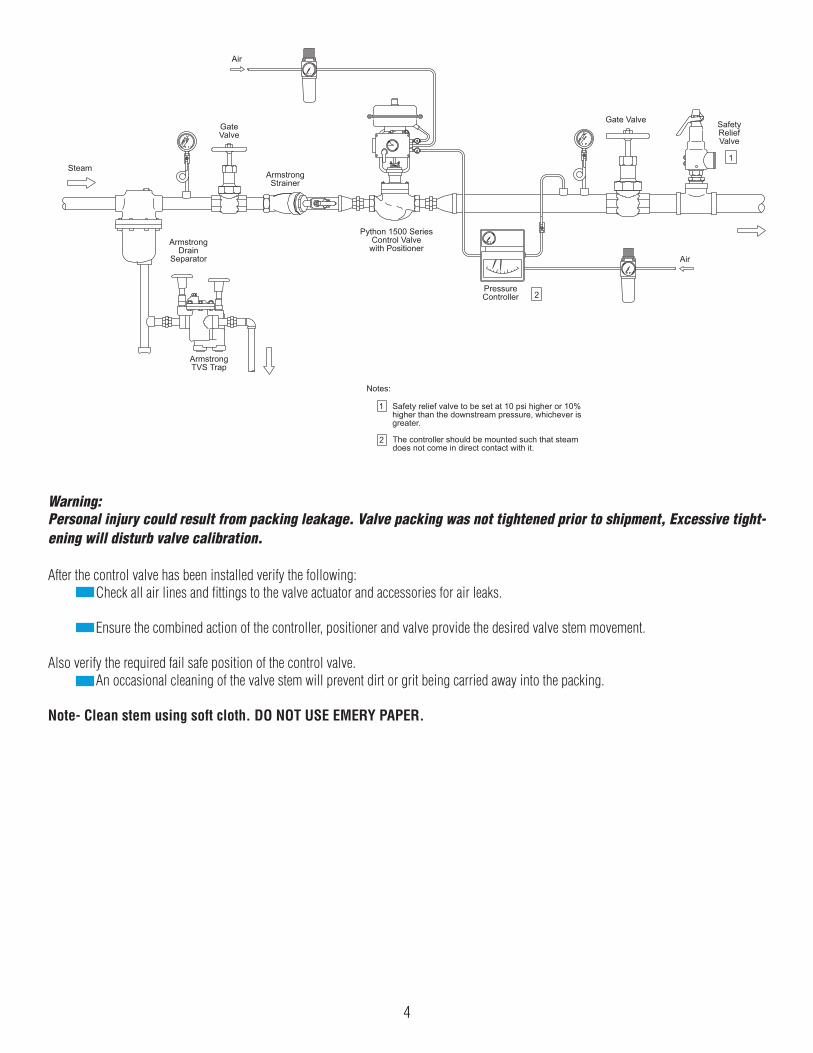
Safety relief valve to be set at 10 psi higher or 10% higher than the downstream pressure, whichever is greater.
The controller should be mounted such that steam does not come in direct contact with it.
2
PressureController
Air
GateValve
ArmstrongStrainer
ArmstrongDrain
Separator
ArmstrongTVS Trap
Steam
Python 1500 SeriesControl Valve
with PositionerAir
SafetyReliefValve
Gate Valve
1
2
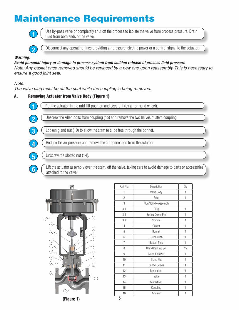
Maintenance RequirementsUse by-pass valve or completely shut off the process to isolate the valve from process pressure. Drain fluid from both ends of the valve.1
Disconnect any operating lines providing air pressure, electric power or a control signal to the actuator.2Warning:Avoid personal injury or damage to process system from sudden release of process fluid pressure.Note: Any gasket once removed should be replaced by a new one upon reassembly. This is necessary toensure a good joint seal.
Note:The valve plug must be off the seat while the coupling is being removed.
A. Removing Actuator from Valve Body (Figure 1)
Put the actuator in the mid-lift position and secure it (by air or hand wheel).1
Unscrew the Allen bolts from coupling (15) and remove the two halves of stem coupling.2
Loosen gland nut (10) to allow the stem to slide free through the bonnet.3
Reduce the air pressure and remove the air connection from the actuator4
Unscrew the slotted nut (14).5
Lift the actuator assembly over the stem, off the valve, taking care to avoid damage to parts or accessories attached to the valve.6
5
Part No. Description Qty
1 Valve Body 1
2 Seat 1
3 Plug Spindle Assembly
3.1 Plug 1
3.2 Spring Dowel Pin 1
3.3 Spindle 1
4 Gasket 1
5 Bonnet 1
6 Guide Bush 1
7 Bottom Ring 1
8 Gland Packing Set 15
9 Gland Follower 1
10 Gland Nut 1
11 Bonnet Scews 4
12 Bonnet Nut 4
13 Yoke 1
14 Slotted Nut 1
15 Coupling 1
16 Actuator 1
(Figure 1)
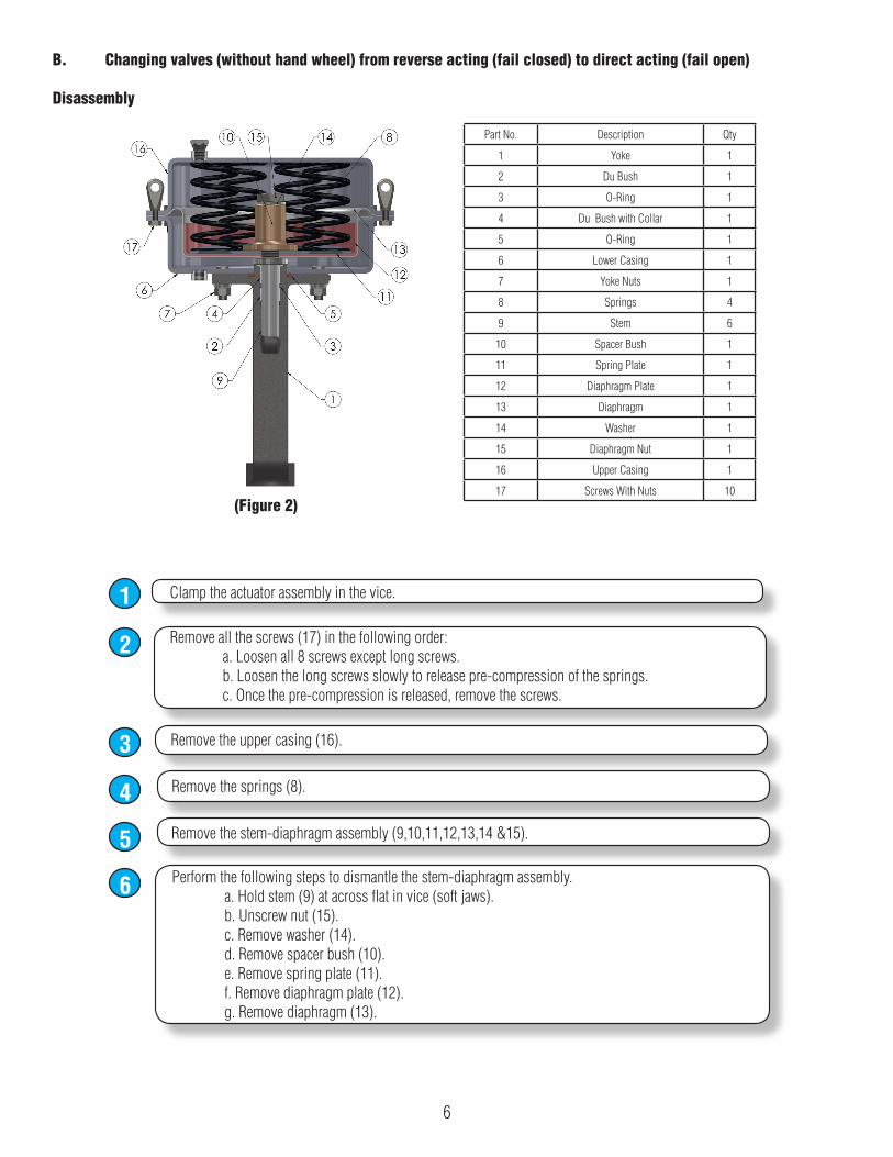
B. Changing valves (without hand wheel) from reverse acting (fail closed) to direct acting (fail open)
Disassembly
Clamp the actuator assembly in the vice.1
Remove all the screws (17) in the following order: a. Loosen all 8 screws except long screws. b. Loosen the long screws slowly to release pre-compression of the springs. c. Once the pre-compression is released, remove the screws.
2
Remove the upper casing (16).3
Remove the springs (8).4
Remove the stem-diaphragm assembly (9,10,11,12,13,14 &15).5Perform the following steps to dismantle the stem-diaphragm assembly. a. Hold stem (9) at across flat in vice (soft jaws). b. Unscrew nut (15). c. Remove washer (14). d. Remove spacer bush (10). e. Remove spring plate (11). f. Remove diaphragm plate (12). g. Remove diaphragm (13).
6
6
Part No. Description Qty
1 Yoke 1
2 Du Bush 1
3 O-Ring 1
4 Du Bush with Collar 1
5 O-Ring 1
6 Lower Casing 1
7 Yoke Nuts 1
8 Springs 4
9 Stem 6
10 Spacer Bush 1
11 Spring Plate 1
12 Diaphragm Plate 1
13 Diaphragm 1
14 Washer 1
15 Diaphragm Nut 1
16 Upper Casing 1
17 Screws With Nuts 10(Figure 2)
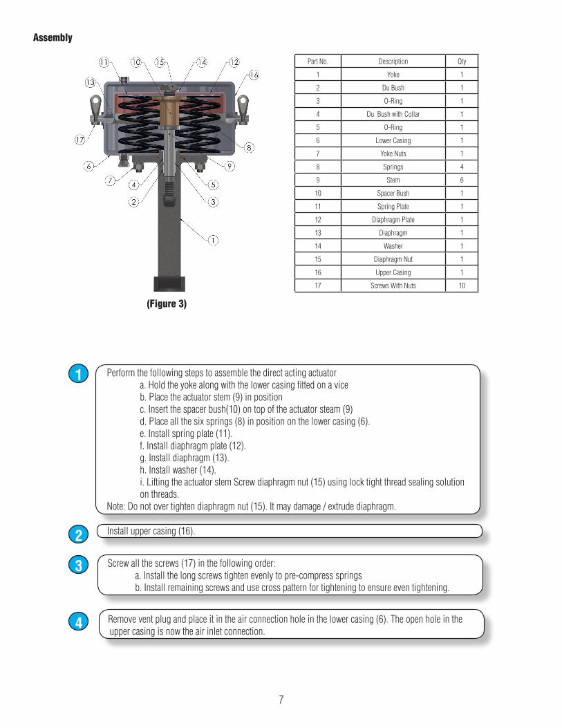
Perform the following steps to assemble the direct acting actuator a. Hold the yoke along with the lower casing fitted on a vice b. Place the actuator stem (9) in position c. Insert the spacer bush(10) on top of the actuator steam (9) d. Place all the six springs (8) in position on the lower casing (6). e. Install spring plate (11). f. Install diaphragm plate (12). g. Install diaphragm (13). h. Install washer (14). i. Lifting the actuator stem Screw diaphragm nut (15) using lock tight thread sealing solution on threads.Note: Do not over tighten diaphragm nut (15). It may damage / extrude diaphragm.
1
Install upper casing (16).2
Screw all the screws (17) in the following order: a. Install the long screws tighten evenly to pre-compress springs b. Install remaining screws and use cross pattern for tightening to ensure even tightening.
3
Remove vent plug and place it in the air connection hole in the lower casing (6). The open hole in the upper casing is now the air inlet connection.
4
Assembly
7
Part No. Description Qty
1 Yoke 1
2 Du Bush 1
3 O-Ring 1
4 Du Bush with Collar 1
5 O-Ring 1
6 Lower Casing 1
7 Yoke Nuts 1
8 Springs 4
9 Stem 6
10 Spacer Bush 1
11 Spring Plate 1
12 Diaphragm Plate 1
13 Diaphragm 1
14 Washer 1
15 Diaphragm Nut 1
16 Upper Casing 1
17 Screws With Nuts 10
(Figure 3)
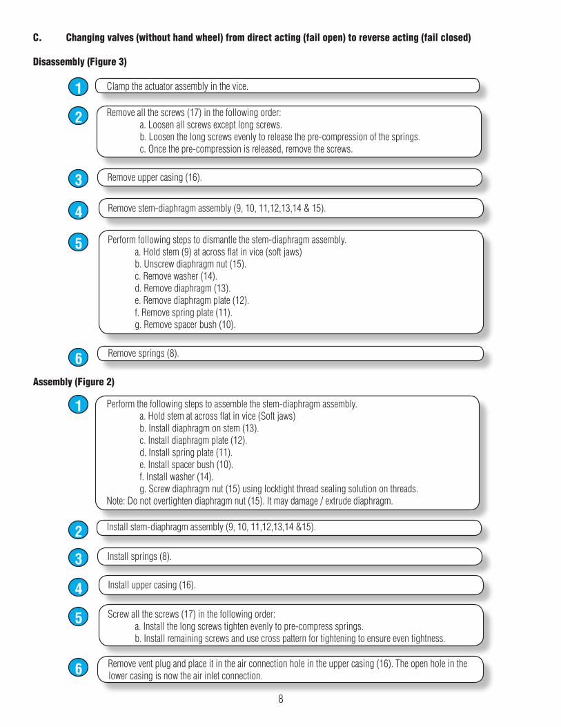
C. Changing valves (without hand wheel) from direct acting (fail open) to reverse acting (fail closed)
Disassembly (Figure 3)
Clamp the actuator assembly in the vice.1
Remove all the screws (17) in the following order: a. Loosen all screws except long screws. b. Loosen the long screws evenly to release the pre-compression of the springs. c. Once the pre-compression is released, remove the screws.
2
Remove upper casing (16).3
Remove stem-diaphragm assembly (9, 10, 11,12,13,14 & 15).4
Perform following steps to dismantle the stem-diaphragm assembly. a. Hold stem (9) at across flat in vice (soft jaws) b. Unscrew diaphragm nut (15). c. Remove washer (14). d. Remove diaphragm (13). e. Remove diaphragm plate (12). f. Remove spring plate (11). g. Remove spacer bush (10).
5
Remove springs (8).6Assembly (Figure 2)
Perform the following steps to assemble the stem-diaphragm assembly. a. Hold stem at across flat in vice (Soft jaws) b. Install diaphragm on stem (13). c. Install diaphragm plate (12). d. Install spring plate (11). e. Install spacer bush (10). f. Install washer (14). g. Screw diaphragm nut (15) using locktight thread sealing solution on threads.Note: Do not overtighten diaphragm nut (15). It may damage / extrude diaphragm.
1
Install stem-diaphragm assembly (9, 10, 11,12,13,14 &15).2
Install springs (8).3
Install upper casing (16).4
Screw all the screws (17) in the following order: a. Install the long screws tighten evenly to pre-compress springs. b. Install remaining screws and use cross pattern for tightening to ensure even tightness.
5
Remove vent plug and place it in the air connection hole in the upper casing (16). The open hole in the lower casing is now the air inlet connection.6
8
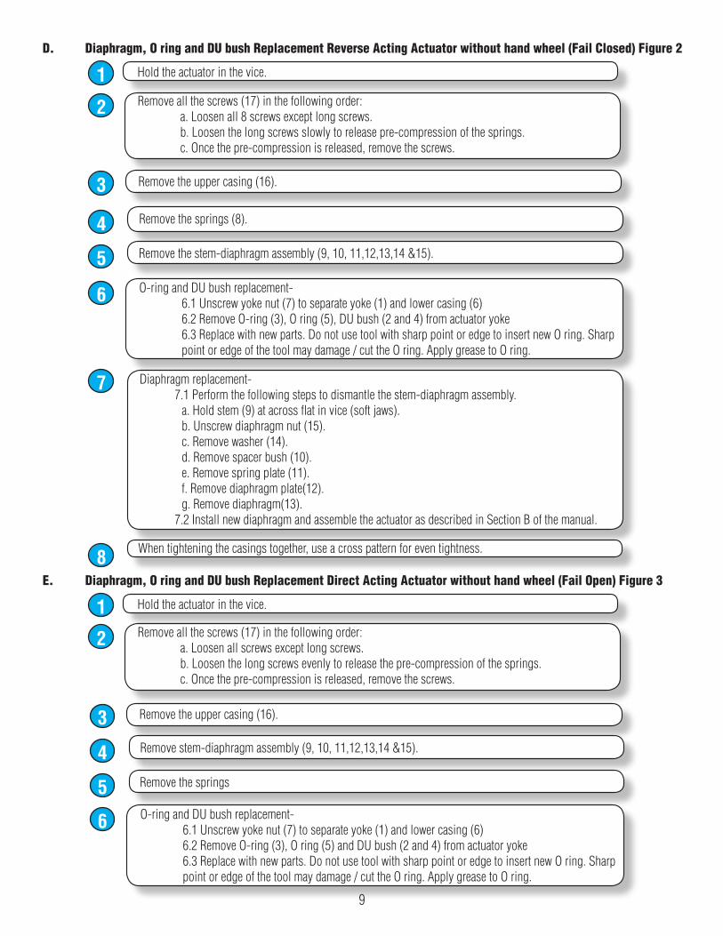
D. Diaphragm, O ring and DU bush Replacement Reverse Acting Actuator without hand wheel (Fail Closed) Figure 2
Hold the actuator in the vice.1Remove all the screws (17) in the following order: a. Loosen all 8 screws except long screws. b. Loosen the long screws slowly to release pre-compression of the springs. c. Once the pre-compression is released, remove the screws.
2
Remove the upper casing (16).3
Remove the springs (8).4Remove the stem-diaphragm assembly (9, 10, 11,12,13,14 &15).5O-ring and DU bush replacement- 6.1 Unscrew yoke nut (7) to separate yoke (1) and lower casing (6) 6.2 Remove O-ring (3), O ring (5), DU bush (2 and 4) from actuator yoke 6.3 Replace with new parts. Do not use tool with sharp point or edge to insert new O ring. Sharp point or edge of the tool may damage / cut the O ring. Apply grease to O ring.
6
Diaphragm replacement- 7.1 Perform the following steps to dismantle the stem-diaphragm assembly. a. Hold stem (9) at across flat in vice (soft jaws). b. Unscrew diaphragm nut (15). c. Remove washer (14). d. Remove spacer bush (10). e. Remove spring plate (11). f. Remove diaphragm plate(12). g. Remove diaphragm(13). 7.2 Install new diaphragm and assemble the actuator as described in Section B of the manual.
7
When tightening the casings together, use a cross pattern for even tightness.8E. Diaphragm, O ring and DU bush Replacement Direct Acting Actuator without hand wheel (Fail Open) Figure 3
Hold the actuator in the vice.1Remove all the screws (17) in the following order: a. Loosen all screws except long screws. b. Loosen the long screws evenly to release the pre-compression of the springs. c. Once the pre-compression is released, remove the screws.
2
Remove the upper casing (16).3Remove stem-diaphragm assembly (9, 10, 11,12,13,14 &15).4Remove the springs5O-ring and DU bush replacement- 6.1 Unscrew yoke nut (7) to separate yoke (1) and lower casing (6) 6.2 Remove O-ring (3), O ring (5) and DU bush (2 and 4) from actuator yoke 6.3 Replace with new parts. Do not use tool with sharp point or edge to insert new O ring. Sharp point or edge of the tool may damage / cut the O ring. Apply grease to O ring.
6
9
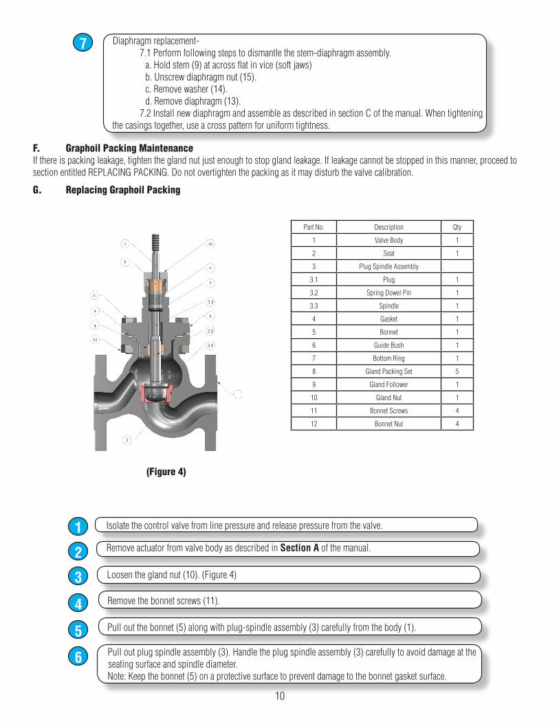
Diaphragm replacement- 7.1 Perform following steps to dismantle the stem-diaphragm assembly. a. Hold stem (9) at across flat in vice (soft jaws) b. Unscrew diaphragm nut (15). c. Remove washer (14). d. Remove diaphragm (13). 7.2 Install new diaphragm and assemble as described in section C of the manual. When tightening the casings together, use a cross pattern for uniform tightness.
7
F. Graphoil Packing MaintenanceIf there is packing leakage, tighten the gland nut just enough to stop gland leakage. If leakage cannot be stopped in this manner, proceed to section entitled REPLACING PACKING. Do not overtighten the packing as it may disturb the valve calibration.
G. Replacing Graphoil Packing
Isolate the control valve from line pressure and release pressure from the valve.1Remove actuator from valve body as described in Section A of the manual.2Loosen the gland nut (10). (Figure 4)3Remove the bonnet screws (11).4Pull out the bonnet (5) along with plug-spindle assembly (3) carefully from the body (1).5Pull out plug spindle assembly (3). Handle the plug spindle assembly (3) carefully to avoid damage at the seating surface and spindle diameter.Note: Keep the bonnet (5) on a protective surface to prevent damage to the bonnet gasket surface.
6
10
Part No. Description Qty
1 Valve Body 1
2 Seat 1
3 Plug Spindle Assembly
3.1 Plug 1
3.2 Spring Dowel Pin 1
3.3 Spindle 1
4 Gasket 1
5 Bonnet 1
6 Guide Bush 1
7 Bottom Ring 1
8 Gland Packing Set 5
9 Gland Follower 1
10 Gland Nut 1
11 Bonnet Screws 4
12 Bonnet Nut 4
(Figure 4)
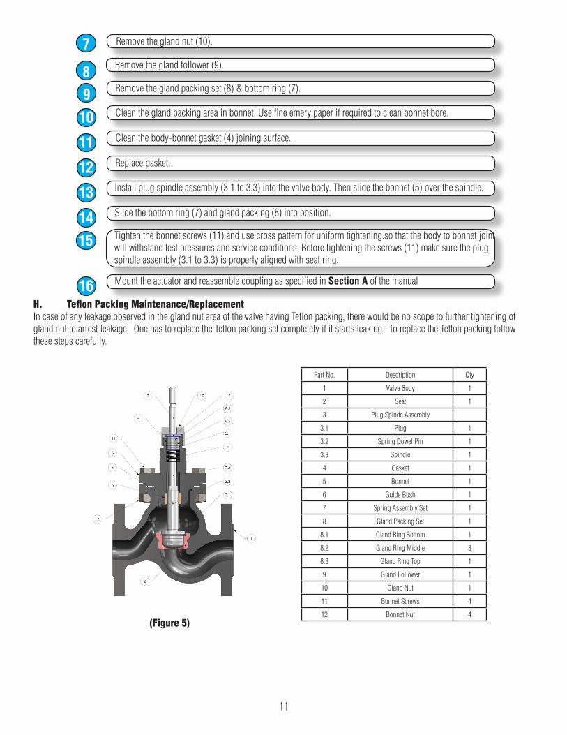
Remove the gland nut (10).7Remove the gland follower (9).8Remove the gland packing set (8) & bottom ring (7).9Clean the gland packing area in bonnet. Use fine emery paper if required to clean bonnet bore.10Clean the body-bonnet gasket (4) joining surface.11Replace gasket.12Install plug spindle assembly (3.1 to 3.3) into the valve body. Then slide the bonnet (5) over the spindle.13Slide the bottom ring (7) and gland packing (8) into position.14Tighten the bonnet screws (11) and use cross pattern for uniform tightening.so that the body to bonnet joint will withstand test pressures and service conditions. Before tightening the screws (11) make sure the plug spindle assembly (3.1 to 3.3) is properly aligned with seat ring.
15
Mount the actuator and reassemble coupling as specified in Section A of the manual16H. Teflon Packing Maintenance/ReplacementIn case of any leakage observed in the gland nut area of the valve having Teflon packing, there would be no scope to further tightening of gland nut to arrest leakage. One has to replace the Teflon packing set completely if it starts leaking. To replace the Teflon packing follow these steps carefully.
11
Part No. Description Qty
1 Valve Body 1
2 Seat 1
3 Plug Spinde Assembly
3.1 Plug 1
3.2 Spring Dowel Pin 1
3.3 Spindle 1
4 Gasket 1
5 Bonnet 1
6 Guide Bush 1
7 Spring Assembly Set 1
8 Gland Packing Set 1
8.1 Gland Ring Bottom 1
8.2 Gland Ring Middle 3
8.3 Gland Ring Top 1
9 Gland Follower 1
10 Gland Nut 1
11 Bonnet Screws 4
12 Bonnet Nut 4(Figure 5)
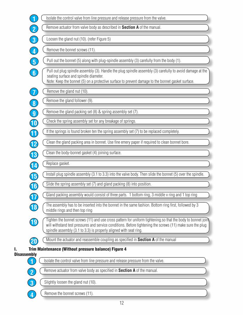
Isolate the control valve from line pressure and release pressure from the valve.1Remove actuator from valve body as described in Section A of the manual.2Loosen the gland nut (10). (refer Figure 5)3Remove the bonnet screws (11).4Pull out the bonnet (5) along with plug-spindle assembly (3) carefully from the body (1).5Pull out plug spindle assembly (3). Handle the plug spindle assembly (3) carefully to avoid damage at the seating surface and spindle diameter.Note: Keep the bonnet (5) on a protective surface to prevent damage to the bonnet gasket surface.
6
Remove the gland nut (10).7Remove the gland follower (9).8Remove the gland packing set (8) & spring assembly set (7).9Check the spring assembly set for any breakage of springs.10If the springs is found broken ten the spring assembly set (7) to be replaced completely.11Clean the gland packing area in bonnet. Use fine emery paper if required to clean bonnet bore.12Clean the body-bonnet gasket (4) joining surface.13Replace gasket.14Install plug spindle assembly (3.1 to 3.3) into the valve body. Then slide the bonnet (5) over the spindle.15Slide the spring assembly set (7) and gland packing (8) into position.16Gland packing assembly would consist of three parts. 1 bottom ring, 3 middle v ring and 1 top ring17The assembly has to be inserted into the bonnet in the same fashion. Bottom ring first, followed by 3 middle rings and then top ring18
Tighten the bonnet screws (11) and use cross pattern for uniform tightening.so that the body to bonnet joint will withstand test pressures and service conditions. Before tightening the screws (11) make sure the plug spindle assembly (3.1 to 3.3) is properly aligned with seat ring.
19
Mount the actuator and reassemble coupling as specified in Section A of the manual20I. Trim Maintenance (Without pressure balance) Figure 4Disassembly
Isolate the control valve from line pressure and release pressure from the valve.1Remove actuator from valve body as specified in Section A of the manual.2Slightly loosen the gland nut (10).3Remove the bonnet screws (11).4
12
Pull out the bonnet (5) along with plug-spindle assembly (3) carefully from the body (1).5Pull out plug spindle assembly (3). Handle the plug spindle assembly (3) carefully to avoid damage at the seating surface and spindle diameter.Note: Keep the bonnet (5) on a protective surface to prevent damage to the bonnet gasket surface.
6
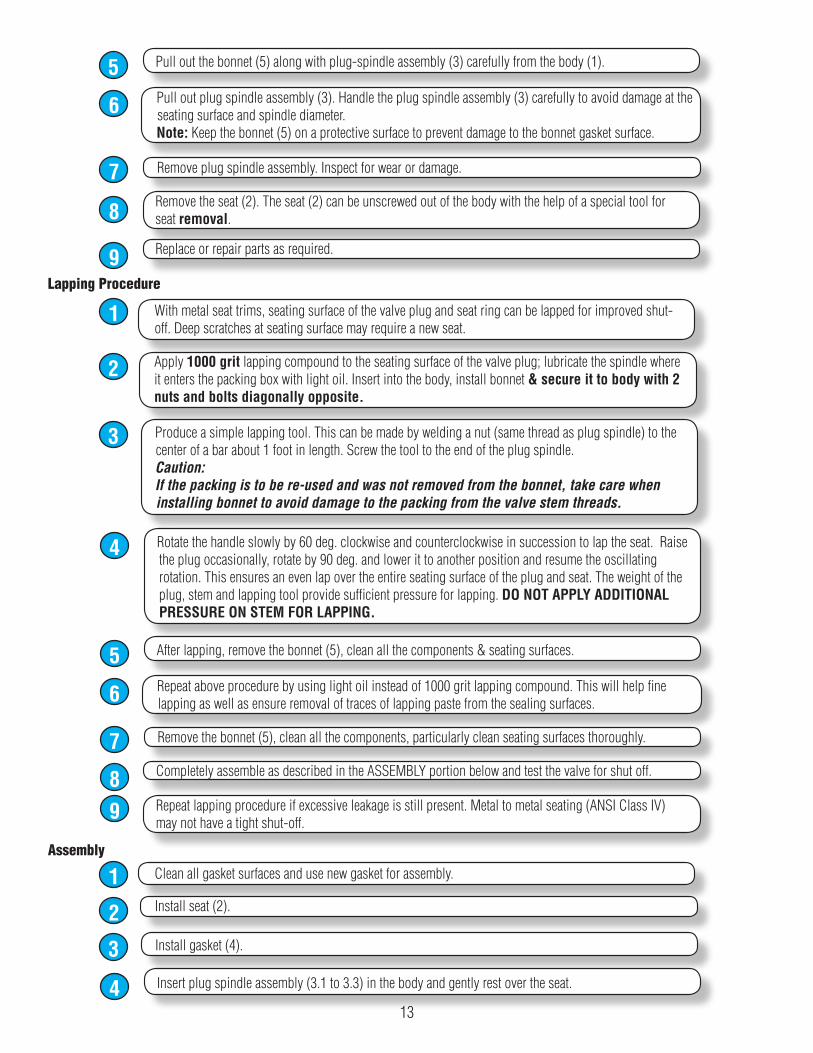
Remove plug spindle assembly. Inspect for wear or damage.7Remove the seat (2). The seat (2) can be unscrewed out of the body with the help of a special tool for seat removal.8
Replace or repair parts as required.9Lapping Procedure
With metal seat trims, seating surface of the valve plug and seat ring can be lapped for improved shut-off. Deep scratches at seating surface may require a new seat.
1
Apply 1000 grit lapping compound to the seating surface of the valve plug; lubricate the spindle where it enters the packing box with light oil. Insert into the body, install bonnet & secure it to body with 2 nuts and bolts diagonally opposite.
2
Produce a simple lapping tool. This can be made by welding a nut (same thread as plug spindle) to the center of a bar about 1 foot in length. Screw the tool to the end of the plug spindle.Caution:If the packing is to be re-used and was not removed from the bonnet, take care when installing bonnet to avoid damage to the packing from the valve stem threads.
3
Rotate the handle slowly by 60 deg. clockwise and counterclockwise in succession to lap the seat. Raise the plug occasionally, rotate by 90 deg. and lower it to another position and resume the oscillating rotation. This ensures an even lap over the entire seating surface of the plug and seat. The weight of the plug, stem and lapping tool provide sufficient pressure for lapping. DO NOT APPLY ADDITIONAL PRESSURE ON STEM FOR LAPPING.
4
After lapping, remove the bonnet (5), clean all the components & seating surfaces.5Repeat above procedure by using light oil instead of 1000 grit lapping compound. This will help fine lapping as well as ensure removal of traces of lapping paste from the sealing surfaces.6
Remove the bonnet (5), clean all the components, particularly clean seating surfaces thoroughly.7Completely assemble as described in the ASSEMBLY portion below and test the valve for shut off.8Repeat lapping procedure if excessive leakage is still present. Metal to metal seating (ANSI Class IV) may not have a tight shut-off.
9
Assembly
Clean all gasket surfaces and use new gasket for assembly.1Install seat (2).2Install gasket (4).3Insert plug spindle assembly (3.1 to 3.3) in the body and gently rest over the seat.4
13
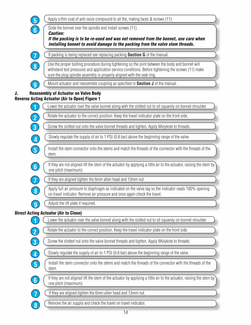
Apply a thin coat of anti-seize compound to all the, mating faces & screws (11).5Slide the bonnet over the spindle and install screws (11).Caution:If the packing is to be re-used and was not removed from the bonnet, use care when installing bonnet to avoid damage to the packing from the valve stem threads.
6
If packing is being replaced see replacing packing Section G of the manual.7Use the proper bolting procedure during tightening so the joint between the body and bonnet will withstand test pressures and application service conditions. Before tightening the screws (11) make sure the plug spindle assembly is properly aligned with the seat ring.
8
Mount actuator and reassemble coupling as specified in Section J of the manual.9J. Reassembly of Actuator on Valve BodyReverse Acting Actuator (Air to Open) Figure 1
Lower the actuator over the valve bonnet along with the slotted nut to sit squarely on bonnet shoulder.1Rotate the actuator to the correct position. Keep the travel indicator plate on the front side.2Screw the slotted nut onto the valve bonnet threads and tighten. Apply Molykote to threads.3Slowly regulate the supply of air to 1 PSI (0.8 bar) above the beginning range of the valve.4Install the stem connector onto the stems and match the threads of the connector with the threads of the stem.
5
If they are not aligned lift the stem of the actuator by applying a little air to the actuator, raising the stem by one pitch (maximum).6
If they are aligned tighten the 6mm allen head and 13mm nut.7Apply full air pressure to diaphragm as indicated on the valve tag so the indicator reads 100% opening on travel indicator. Remove air pressure and once again check the travel.8
Adjust the lift plate if required.9Direct Acting Actuator (Air to Close)
Lower the actuator over the valve bonnet along with the slotted nut to sit squarely on bonnet shoulder.1Rotate the actuator to the correct position. Keep the travel indicator plate on the front side.2Screw the slotted nut onto the valve bonnet threads and tighten. Apply Molykote to threads.3Slowly regulate the supply of air to 1 PSI (0.8 bar) above the beginning range of the valve.4Install the stem connector onto the stems and match the threads of the connector with the threads of the stem.
5
If they are not aligned lift the stem of the actuator by applying a little air to the actuator, raising the stem by one pitch (maximum).6
If they are aligned tighten the 6mm allen head and 13mm nut.7Remove the air supply and check the travel on travel indicator.8
14
Limited Warranty and Remedy
Armstrong International, Inc. or the Armstrong division that sold the product (“Armstrong”) warrants to the original user of those products supplied by it and used in the service and in the manner for which they are intended, that such products shall be free from defects in material and workmanship for a period of one (1) year from the date of installation, but not longer than 15 months from the date of shipment from the factory, [unless a Special Warranty Period applies, as listed below]. This warranty does not extend to any product that has been subject to misuse, neglect or alteration after ship-ment from the Armstrong factory. Except as may be expressly provided in a written agreement between Armstrong and the user, which is signed by both parties, Armstrong DOES NOT MAKE ANY OTHER REPRESENTATIONS OR WAR-RANTIES, EXPRESS OR IMPLIED, INCLUDING, BUT NOT LIMITED TO, ANY IMPLIED WARRANTY OF MERCHANTABILITY OR ANY IMPLIED WARRANTY OF FITNESS FOR A PARTICULAR PURPOSE.
The sole and exclusive remedy with respect to the above limited warranty or with respect to any other claim relating to the products or to defects or any condition or use of the products supplied by Armstrong, however caused, and whether such claim is based upon warranty, contract, negligence, strict liability, or any other basis or theory, is limited to Armstrong’s repair or replacement of the part or product, exclud-ing any labor or any other cost to remove or install said part or product, or at Armstrong’s option, to repayment of the purchase price. As a condition of enforcing any rights or remedies relating to Armstrong products, notice of any warranty or other claim relating to the products must be given in writing to Armstrong: (i) within 30 days of last day of the applicable warranty period, or(ii) within 30 days of the date of the manifestation of the condition or occurrence giving rise to the claim, whichever is earlier. IN NO EVENT SHALL ARMSTRONG BE LIABLE FOR SPECIAL, DIRECT, INDIRECT, INCIDENTAL OR CONSEQUENTIAL DAMAGES, IN-CLUDING, BUT NOT LIMITED TO, LOSS OF USE OR PROFITS OR INTERRUPTION OF BUSINESS. The Limited Warranty and Remedy terms herein apply notwithstanding any contrary terms in any purchase order or form submitted or issued by any user, purchaser, or third party and all such contrary terms shall be deemed rejected by Armstrong.
15

Armstrong International 816 Maple Street, Three Rivers, MI 49093 – USA Phone: (269) 273-1415 Fax: (269) 278-6555 armstronginternational.com
652Printed in U.S.A. - 9/14
© 2014 Armstrong International, Inc.