Embed Size (px)
Citation preview

CVI Assembly Systems

Generation: excellence in FROM THE SIMPLEST TO THE MOST DEMANDI
2
A STATE-OF-THE-ART COMPLETEAND HOMOGENEOUS RANGE:From the single-channel “CVIS” to the“MULTICVI” 32-channel system applica-tions, GEORGES RENAULT offers a rangeevolution based on a common core, themain elements of which are the following:
Fixed and Portable ToolsThe portable electric tightening tools ofthe “ER” range or fixed type of the “EM”range can be connected with all types of controllers or racks. Thanks to theirintegrated memory board, they are automatically recognised by the systemto which they are connected.
Motor ServodriveCommon to the whole range and basedon a 100% GEORGES RENAULT concept,the servodrive is optimised to control the various electric motors installed ontightening tools.
Control BoardThanks to its real time monitor, it controlsthe operation of the servodrive, the tightening cycle and communication withthe outside at the same time.
“CVIPC” 2000 SoftwareThe single CVIPC software combines thePC user-friendliness and memory size withthe functionalities of control systems. It can be used with all systems and allowsthe user to program from the simplest tothe most sophisticated cycle.Besides, it can centralise the results ofnetworked controllers and allows the userto test the good working order of toolsand controllers at any time.

assemblyNG APPLICATIONS
3
The ISaGRAF Workbench adds
to the control systems the functionali-ties of a “mini-PLC” capable of control-ling simple applications.
Industrial Networks:MODBUS, UniTelway, FIP, PROFIBUS, DEVICENET, INTERBUS S (Please consult us for further information)

The “all-integrated, all-digit
4
ELECTRIC MOTORTools are equipped with a three-phase A.C. servo motor.Current sine control ensures perfect control of the speedand motor stop thus providing the operator a smooth torquereaction.
TORQUE TRANSDUCERAnalog signal of the torque transducer is processed anddigitised as close as possible to the strain gauge. Torquevalues are then transferred to the controller via a high-speed digital link. Sensitivity and nominal load of the transducer are optimised to the nominal torque of the tool.
RESOLVERThe resolver technology allows precisepositional sensing of the motor (4095points per rotation). The control of the
motor phases is therefore more accurate.The angular counting is processed from the
resolver signals. The resolution of the rotational angle is0.10°.
Memory board
Strain gauges
Memory board
Up to 45 mHigh-speed digital link
500 KbaudElectronic processing of the
torque analog signal
Motor/Resolver/Torque + tool features
Torque + tool features
Motor/Resolver
Motor with
built-in resolver
Motor withbuilt-in resolver
DIGITAL CONCEPT
MEMORYThe controller automatically recognizes the tool features by reading the tool built-in memory board. The sensitivity value, the number of cycles run by the tool, the year of
manufacturing, the date of the last maintenance opera-tion are constantly available to maintenance technicians.Linearity and calibration accuracy of the transducer arepermanently controlled.
al” technology
5
1ST APPLICATION: 2ND APPLICATION:
The signals of both transducers are multiplexed on the sametorque cable. As soon as the drift between the two transducersexceeds a programmed value, the control system generates an alarm which can be interpreted by the user.A second angle encoder can be added to the torque unit. This angle encoder is used as a stand-by unit.
The second transducer can beconnected to a torque meterused to check that the torquevalue applied is correct.
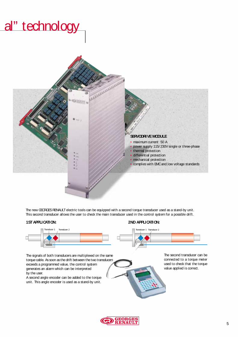
The new GEORGES RENAULT electric tools can be equipped with a second torque transducer used as a stand-by unit.This second transducer allows the user to check the main transducer used in the control system for a possible drift.
SERVODRIVE MODULE• maximum current: 50 A• power supply 115/230V single or three-phase• thermal protection• differential protection• mechanical protection• complies with EMC and low voltage standards
Transducer 1 Transducer 2 Transducer 1 Transducer 2

6
CONTROL SCREENS:• Display of torque and angle values,mean and range of the last 5 results andtolerances.• A comment is added for each cyclenumber.
MAINTENANCE SCREEN:• Autotest of the complete system.• Spindle rotation test.• Input/Output selection.• Date of the last maintenance operation.• Total cycle counter.• Daily counter.
CHANGING CYCLE PROGRAMMING:• The operator can change the tighteningstrategy and the torque and angle values(minimum, target, maximum) at any time.• Additional cycles can be created usingthe “CVISPC” software delivered with thecontroller.
CONTROLLER
SINGLE-CHANNEL CONTROLLER FOR ELECTRIC PORTABLE OR FIXED TOOLS.The CVIS control system can control a portable “ER” type or fixed “EM” type electric tool.
The CVIS+TOOL+CABLE assembly is ready to start producing immediately, requiring the input of torque and angle parameters only.
The all-digital concept of the controller + tool assembly provides more safety for the operator and offers higher tightening performance. Signalsfrom torque transducer are processed and digitised as close as possible to the strain gauge and sent to the controller via a fast digital link.
15 tightening cycles can be divided into a maximum of 20 elementary phases. The logical and structured programming allows a fine-tuningof critical joints via direct friendly displays.
With the FlashEprom memory, the software can be upgraded without changing components.
TIGHTENING OR LOOSENING STRATEGIES:• Torque and angle• Angle and torqueDuring each cycle phase, the motor power is fully monitored.
PERIPHERALS
NUMBER OF INPUT 8NUMBER OF OUTPUT 6EMERGENCY STOP 1SERIAL PORT 1 (RS 232 / 485)PRINTER 1 (PARALLEL CENTRONIX)
TECHNICAL FEATURES
NUMBER OF CYCLES 15NUMBER OF PHASES 8 per cycleMEMORY SIZE From 1,000 to 3,000 tightening results according to the programmed number of cyclesMAINS SUPPLY Single-phase 115-230 Volts with automatic switchingAMPERAGE 16 A (115 V) - 8 A (230 V)WEIGHT 15 kgDIMENSIONS Width 280 mm – Height 365 mm – Depth. 440 mm
The controller complies with the current EC standards. Optional wall hanging system

7
6 LED for torque and angle
report display
Parallel connection forany type of printer
PC connection to create new cycles, process curves
and statistics and implementthe network
“Direct” printing ofthe last tightening results
LCD with backlighting
How to orderPART NUMBER
CVIS controller 615 932 301 0
START-UP KIT TO BE ORDERED WITH THECONTROLLERIncluding: Outlet + literature + P.C connector and software
Outlet Literature KIT
A French 615 928 005 0C English 615 928 006 0A English 615 928 010 0D English 615 928 012 0B English 615 928 014 0A German 615 928 007 0A Spanish 615 928 008 0E Italian 615 928 009 0A Dutch 615 928 013 0
OPTIONAL ACCESSORIES
PART NUMBER
CVIS/CVIC.PC2000 Software 615 927 511 0CVINET.PC2000 Software 615 927 513 0PC cable 2 m 615 917 047 0Printer cable 2 m 615 917 057 0Wall hanging system 615 930 519 0Power supply 400 Volts 615 932 460 0
A B C D E
Single or two-spindle cont
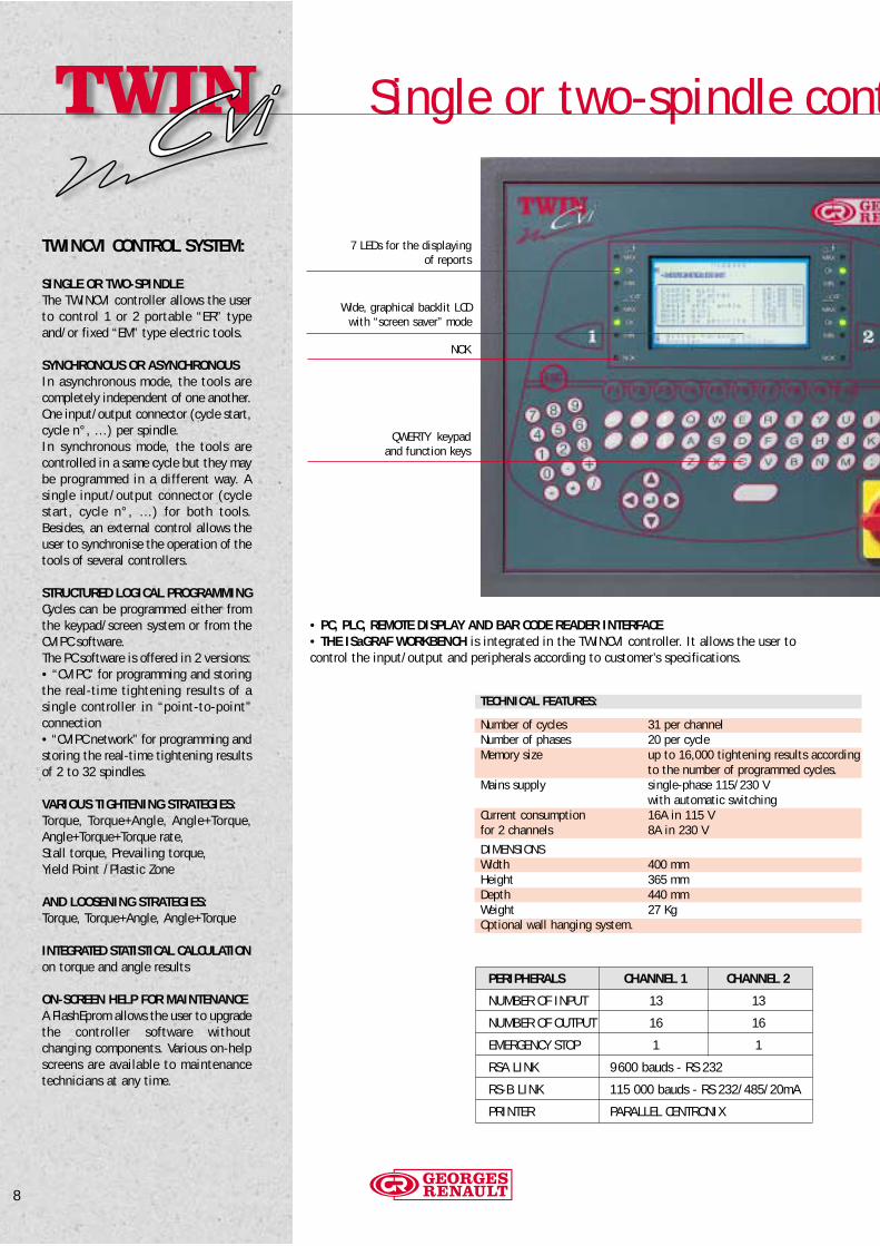
7 LEDs for the displayingof reports
Wide, graphical backlit LCDwith “screen saver” mode
NOK
QWERTY keypadand function keys
8
• PC, PLC, REMOTE DISPLAY AND BAR CODE READER INTERFACE• THE ISaGRAF WORKBENCH is integrated in the TWINCVI controller. It allows the user to control the input/output and peripherals according to customer’s specifications.
TWINCVI CONTROL SYSTEM:
SINGLE OR TWO-SPINDLEThe TWINCVI controller allows the userto control 1 or 2 portable “ER” typeand/or fixed “EM” type electric tools.
SYNCHRONOUS OR ASYNCHRONOUSIn asynchronous mode, the tools arecompletely independent of one another.One input/output connector (cycle start,cycle n°, …) per spindle.In synchronous mode, the tools arecontrolled in a same cycle but they maybe programmed in a different way. Asingle input/output connector (cyclestart, cycle n°, …) for both tools.Besides, an external control allows theuser to synchronise the operation of thetools of several controllers.
STRUCTURED LOGICAL PROGRAMMINGCycles can be programmed either fromthe keypad/screen system or from theCVIPC software.The PC software is offered in 2 versions:• “CVIPC” for programming and storingthe real-time tightening results of asingle controller in “point-to-point”connection• “CVIPC network” for programming andstoring the real-time tightening resultsof 2 to 32 spindles.
VARIOUS TIGHTENING STRATEGIES:Torque, Torque+Angle, Angle+Torque,Angle+Torque+Torque rate, Stall torque, Prevailing torque, Yield Point /Plastic Zone
AND LOOSENING STRATEGIES:Torque, Torque+Angle, Angle+Torque
INTEGRATED STATISTICAL CALCULATIONon torque and angle results
ON-SCREEN HELP FOR MAINTENANCEA FlashEprom allows the user to upgradethe controller software without changing components. Various on-helpscreens are available to maintenancetechnicians at any time.
TECHNICAL FEATURES:
Number of cycles 31 per channelNumber of phases 20 per cycleMemory size up to 16,000 tightening results according
to the number of programmed cycles.Mains supply single-phase 115/230 V
with automatic switchingCurrent consumption 16A in 115 Vfor 2 channels 8A in 230 V
DIMENSIONSWidth 400 mmHeight 365 mmDepth 440 mmWeight 27 KgOptional wall hanging system.
PERIPHERALS CHANNEL 1 CHANNEL 2
NUMBER OF INPUT 13 13
NUMBER OF OUTPUT 16 16
EMERGENCY STOP 1 1
RSA LINK 9600 bauds - RS 232
RS-B LINK 115 000 bauds - RS 232/485/20mA
PRINTER PARALLEL CENTRONIX
rol System
9
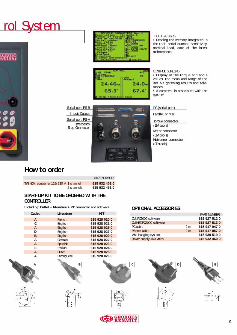
CONTROL SCREENS• Display of the torque and anglevalues, the mean and range of thelast 5 tightening results and tole-rances• A comment is associated with thecycle n°
TOOL FEATURES• Reading the memory integrated inthe tool: serial number, sensitivity,nominal load, date of the latest maintenance.
Serial port RS-A
Serial port RS-B
EmergencyStop Connector
Input/Output
PC (serial port)
Parallel printer
Torque connector(EM tools)
Nutrunner connector(ER tools)
Motor connector(EM tools)
OPTIONAL ACCESSORIESPART NUMBER
CVI.PC2000 software 615 927 512 0CVINET.PC2000 software 615 927 513 0PC cable 2 m 615 917 047 0Printer cable 2 m 615 917 057 0Wall hanging system 615 930 519 0Power supply 400 Volts 615 932 460 0
How to orderPART NUMBER
TWINCVI controller 115/230 V 1 channel 615 932 401 02 channels 615 932 451 0
START-UP KIT TO BE ORDERED WITH THECONTROLLERIncluding: Outlet + literature + P.C connector and software
Outlet Literature KIT
A French 615 928 020 0C English 615 928 021 0A English 615 928 025 0D English 615 928 027 0B English 615 928 029 0A German 615 928 022 0A Spanish 615 928 023 0E Italian 615 928 024 0A Dutch 615 928 028 0A Portuguese 615 928 026 0
A B C D E

SPC, Printouts and Mainte
10
INTEGRATED STATISTICALCALCULATIONCalculation of CAM, CP, CPK, meanand range of the torque & angleresults according to ISO or CNOMO stan-dards.
Main features:• filtering of data (date or value
interval)• selection of the interval of tole-
rances• “distribution regular” test• “law normal” test• mean, standard deviation, CAM,
CP, CPK• editing of results, histogram• editing of “control charts”
“Mean, standard deviation” control chart
Histogram
Statistical results

nance
T
T
ACCEPT
REJECT
11
PRINTOUT OF RESULTSAs a standard, a specific menu in the CVIPCsoftware allows the user to create his own format of printouts. This format is parti-cularly adapted to a label printer.
For example:• a reject report will be printed in red• an accept report will be printed in black• automatic positioning on the next label
Example of personal format of printouts
CALIBRATION AND MAINTENANCE
MAINTENANCE HELPat all levels: at the time of installation, during programming operations and when the controller is operating,trouble-shooting help screens are proposed to the user.Input/output display to check the continuity of connections between the controller and the PLC.
CALIBRATION AND MAINTENANCEThe controller and the tool are automatically calibratedby the system. A special cycle is used for thecomplete test of the torque and angle measuring line. Two types of calibration are proposed:- dynamic calibration- static calibrationThey allow the user to correct a possible drift of the torque transducer.
“Dynamic mode” calibration of thesensitivity of the torque transducerthanks to the COSMOS 5000 measuringunit.
EXAMPLE OF A STANDARD FORMAT:
Reading no Sp Cy Ph Date Hour Torque Angle Torque rate RENm dg Nm/dg
1223 02 03 00 09/03/98 18:04:58 0030.2 0120.5 0.5680 A

12
The ISaGRAF Workbench allows the userto add to the control systems of the CVIrange the functionalities of a “mini-PLC”capable of controlling simple applications.An ISaGRAF standard program is integratedin each system to control the input/outputand various peripherals.The user can create or modify the existingprogram to adjust it to his application.The programs are developed and finalisedon a PC with a multilingual WINDOWS environment.The development of software programs withISaGRAF includes 3 stages:• writing the program using standardisedlanguages (for example: SFC language)• developing the application with the codegenerator and debugger• downloading the program towards theapplication (the tightening controller).
PROGRAMMING LANGUAGES AVAILABLE:• SFC language• LD language• FDB function block chart• “Pascal” type advanced language (ST)• “Assembly” type first level language (IL)
TOOLS OF THE ISaGRAF SOFTWARE ENVIRONMENT:• editors to write the application• a code generator• a debugger
TYPES OF APPLICATIONS:• controlling a socket tray (defining a cyclesequence with a visual display of the pickingof a socket)• stand-alone stations with control of station input, elevator, station output, flow,defects, etc…• reading/writing embedded labels• specific printers equipped with a bar codereader• message control on remote displays or terminals
SAMPLE SFC PROGRAM
STRUCTURE
Integrated “ISaGRAF” Workbench
13
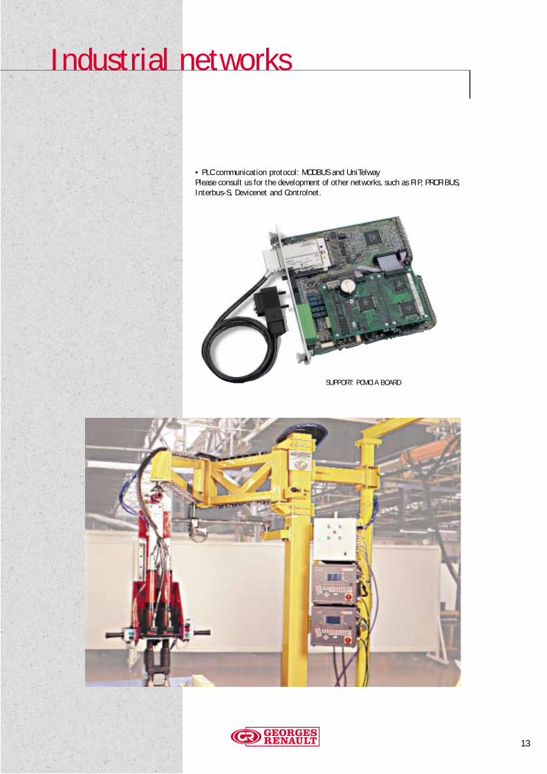
• PLC communication protocol: MODBUS and UniTelwayPlease consult us for the development of other networks, such as FIP, PROFIBUS,Interbus-S, Devicenet and Controlnet.
SUPPORT: PCMCIA BOARD
Industrial networks
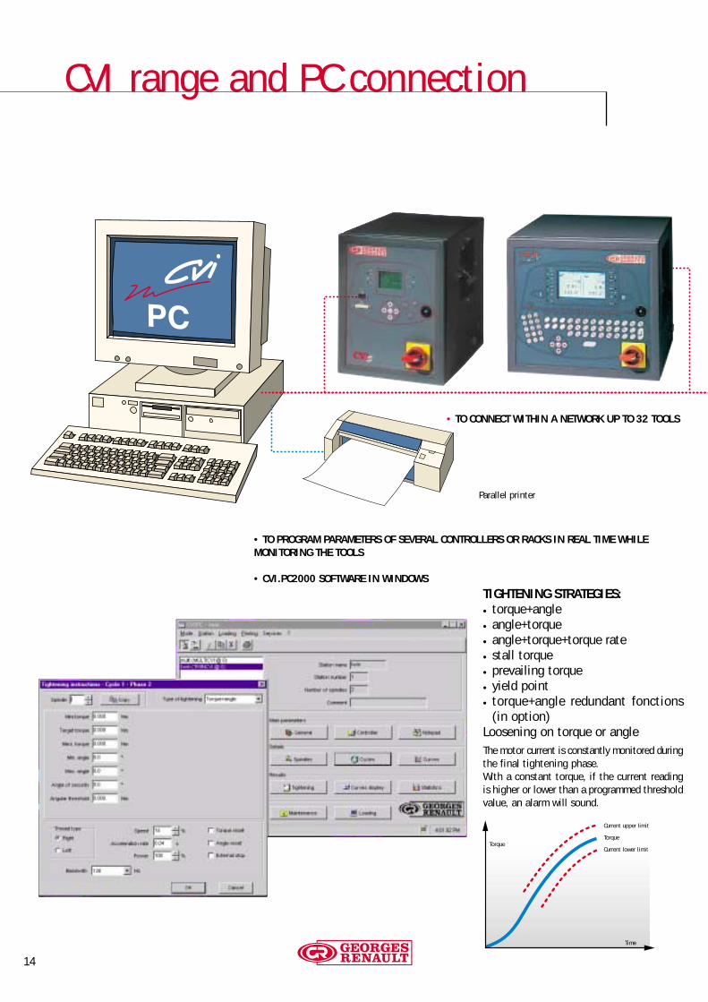
CVI range and PC connection
14
Parallel printer
• TO PROGRAM PARAMETERS OF SEVERAL CONTROLLERS OR RACKS IN REAL TIME WHILE MONITORING THE TOOLS
• CVI.PC2000 SOFTWARE IN WINDOWS
Current upper limit
Torque
Current lower limit
Time
Torque
• TO CONNECT WITHIN A NETWORK UP TO 32 TOOLS
TIGHTENING STRATEGIES:• torque+angle• angle+torque• angle+torque+torque rate• stall torque• prevailing torque• yield point• torque+angle redundant fonctions
(in option)Loosening on torque or angleThe motor current is constantly monitored duringthe final tightening phase.With a constant torque, if the current readingis higher or lower than a programmed thresholdvalue, an alarm will sound.

15
OTHER MAJOR BENEFITS OF THE PC :
• to increase memory capacity to save upto 1,000,000 results (for 32 spindles) and20 tightening curves
• to display and edit SPC on torque andangle results
• to backup on floppy disk parameters andresults to ensure the traceability of theapplications
• to transfer data to spreadsheet (resultsand curves)

MODCVI, MULTICVI for mulSpecial machines upon request manufactured by our ap
16
THE MODCVI IS THE RACKALBLE OF THE TWINCVIAlthough it has no keypad or display, itcan perform all the functions of theTWINCVI, and is programmed with theCVIPC software which is also used to dis-play the results.
The MODCVI is supplied in two configurations:
• “INTEGRATED” CONFIGURATIONThe supplied modules are installed/wired ina cabinet, ready for use.
• COMPLETE CABINET CONFIGURATIONincluding transformer power supply, air-conditioning and full documentation of electrical drawings. The installation can besupplied complete in accordance to the customer’s specifications.
THE MULTICVIis supplied in the same types of configurationas the MODCVI.It is capable of controlling from 3 to 32tools.
The MULTICVI consists of several MODCVIS- according to the number of connected tools - and a CPUCVI module to provide theinterface between the station PLC and thecontrol modules.
The CPUCVI is the system intelligence.It fully controls the tightening sequence,centralises the controls and controls theMODCVI modules.In the event of incorrect results, it authorizescycle restarts.
power supply 3 x 115/230V
indicator lights oftightening report per tool
servodrive(1 per tool)
single-phase powersupply 115/230V
internal power board
parallel input/output,channel 1
parallel input/output,channel 2
peripheral connection block(printer, PC, serial ports)
MODCVI MODULE
“Tightening wheel” assembly machine with 3 or 4 spindles changing (France)
16

tispindle applicationspplication center. PLEASE ASK OUR DEPARTMENT.
17
Sample layout:26-spindle MULTICVI CABINET supplied in integrated version.

« ER » Portable Electric Nutrunners
18
PHOTO MODEL PART TORQUE ROTATIONAL RÉDUCTION SENSITIVITY/ SQUARE LENGTH WEIGHTNO. NUMBER RANGE SPEED GEAR NOMINAL LOAD DRIVE
Nm ft.lb tr/min. mV/V/Nm inch mm kg
ANGLE-HEAD :A 615 165 078 0 ERA20J 5 - 20 / 3.7 - 14.8 1140 15,15 1,0 / 20 3/8 447 2,0A 615 165 079 0 ERA30J 5 - 30 / 3.7 - 22.1 880 19,69 1,5 / 30 3/8 447 2,0A 615 165 080 0 ERA40J 8 - 40 / 6 - 29.5 690 24,94 1,6 / 40 3/8 458 2,1A 615 165 081 0 ERA60J 15 - 60 / 11 - 44.2 440 39,41 1,8 / 60 3/8 469 2,2A 615 165 082 0 ERA70J 15 - 70 / 11 - 51.6 530 27,20 1,2 / 70 1/2 552 3,5A 615 165 083 0 ERA90J 20 - 90 / 14.7 - 66.3 420 34,13 1,6 / 90 1/2 552 3,5A 615 165 084 0 ERA115J 25 - 115 / 18.4 - 84.8 290 49,65 1,4 / 115 1/2 552 3,5A 615 165 085 0 ERA125J 30 - 125 / 22.1 - 92.1 280 50,57 1,2 / 125 1/2 554 3,6A 615 165 086 0 ERA150J 35 - 150 / 25.8 - 110.6 230 62,30 1,4 / 150 1/2 554 3,6A 615 165 012 0 ER180J 40 - 180 / 29.5 - 132.7 190 75,85 1,9 / 180 3/4 568 3,8A 615 165 123 0 ERA200J* 60 - 200 / 44.2 - 147.5 170 82,94 1,4 / 200 3/4 604 3,9A 615 165 070 0 ERA300-6J 100 - 300 / 73.7 - 221 190 45,00 1,2 / 300 3/4 702 8,0A 615 165 071 0 ERA400-6J 100 - 400 / 73.7 - 294.8 150 58,78 1,6 / 400 3/4 702 8,0
IN-LINE :B 615 165 060 0 ERD5J 1 - 6 / 0.7 - 4.4 1590 10,89 1 / 10 hex 1/4 - 1,3B 615 165 072 0 ERD20J 3 - 20 / 2.2 - 14.7 1200 14,44 1,3 / 20 hex 1/4 1,8B 615 165 073 0 ERD30J 5 - 30 / 3.7 - 22.1 850 20,25 1,3 / 30 3/8 - 1,8B 615 165 074 0 ERD50J 20 - 50 / 14.7 - 36.8 790 18,06 1,3 / 50 3/8 - 2,8B 615 165 075 0 ERD70J 20 - 70 / 14.7 - 51.6 500 28,44 1,8 / 70 1/2 - 2,8B 615 165 062 0 ERD120J 30 - 120 / 22.1 - 88.4 310 46,66 1,4 / 120 1/2 - 3,3
PISTOL GRIP :C 615 165 061 0 ERP5J 0,5 - 6 / 0.4 - 4.4 1590 10,89 1 / 10 hex 1/4 - 1,2C 615 165 002 0 ER20PJ 2 - 20 / 1.5 - 14.7 1010 17,10 1,3 / 20 hex 1/4 - 1,8C 615 165 005 0 ER30PJ 4 - 30 / 2.9 - 22.1 680 25,50 1,3 / 30 3/8 - 1,8
* Available from the end of 2000
Note : the suffix J indicates a model with built-in torque transducer. To order a model without transducer, please consult.
A
B
C
DATA SHEETS ON REQUEST

19
GEARED OFFSET HEADSThe geared offset heads are used in special applications such ashydraulic connection. They can replace the socket on the nutrun-ner angle head and provide a connection for a ring spanner. Thecontroller has a special function to allow the user to re-index thegeared offset head to the open position after tightening.
INDICATOR BOXPART NUMBER
Indicator box 615 936 001 0
BALANCERSCAPACITY LENGTH WEIGHT PART NUMBER
Mini Maxi m kg1,4 - 2,4 kg 1,5 0,6 505422,0 - 5,0 kg 2,4 2,7 500525,0 - 7,0 kg 2,4 3,2 50062
Other on request
PART NUMBERSocket tray (sockets are not supplied) 615 936 005 0Cable for socket tray Length 1 m 615 917 241 0
Length 5 m 615 917 242 0Length 10 m 615 917 244 0Length 15 m 615 917 245 0
CABLES AND CABLE EXTENSIONS
SOCKET TRAYSSocket trays can automatically select a cycle on picking of the appropriate socket. The corresponding light comes on to indicatethe selected cycle.
ACCESSORIES PART NUMBER
Fixed suspension bail 615 571 050 0Suspension bail on a swivel 615 396 041 0Suspension bail on a swivel for:ERD5/20/30J 615 396 121 0ERA20/30/40/60J 615 396 121 0ERD50/70/120J 615 396 122 0ERA70/90/115/150/200J 615 396 122 0
Reaction bar ring for:ERA70/90/115/150J 615 396 227 0ERA200J 615 396 230 0ER/180J 615 396 043 0
LENGTH PARTin m NUMBER
Nutrunner cable 5 615 917 072 0Nutrunner cable 10 615 917 074 0Nutrunner cable 15 615 917 075 0Extension cable 10 615 917 084 0Extension cable 15 615 917 085 0Extension cable 20 615 917 086 0Extension cable 25 615 917 087 0Extension cable 30 615 917 088 0
Adapteur ER pour MODCVI 615 917 151 0
Nutrunner model with 20 mm telescoping.Please consult us for detailed specifications.

Fixed “EM” and “EML” series Electric To
20
Note: the suffix J indicates a model with built-in torque transducer.
DATA SHEETS ON REQUEST
A
PHOTO PART MODEL TORQUE ROTATIONAL SENSITIVITY/ MIN. DIST. SQUARE LENGTH STROKE WEIGHTNO. NUMBER RANGE SPEED NOMINAL LOAD BETWEEN CENTERS DRIVE
Nm ft.lb r.p.m. mV/V/Nm mm inch mm mm kg
STRAIGHTA 615 165 013 0 EM35-10J 1 - 8 / 0.7 - 5.9 1590 1,9 / 8 43,2 3/8 - 50 1,7A 615 165 014 0 EM35-20J 4 - 15 / 2.9 - 11 1590 1,4 / 25 43,2 3/8 - 50 2,0A 615 165 015 0 EM38-10J 9 - 30 / 6.6 - 22.1 990 1,4 / 50 43,2 3/8 - 50 2,0A 615 165 016 0 EM38-20J 10 - 45 / 7.4 - 33.2 840 1,4 / 50 43,2 3/8 - 50 2,0A 615 165 017 0 EM51-10J 20 - 70 / 14.7 - 51.6 500 1,4 / 100 51,2 1/2 - 50 2,9A 615 165 018 0 EM51-20J 30 - 135 / 22.1 - 99.5 310 1,6 / 150 51,2 1/2 - 50 3,5A 615 165 019 0 EM60-10J 20 - 95 / 14.7 - 70 710 1,4 / 150 60,2 1/2 - 50 4,8A 615 165 020 0 EM60-20J 50 - 175 / 36.8 - 129 390 1,4 / 300 60,2 3/4 - 50 4,8A 615 165 021 0 EM60-30J 70 - 250 / 51.6 - 184.2 230 1,4 / 300 60,2 3/4 - 50 5,2A 615 165 022 0 EM80-10J 80 - 300 / 59 - 221 220 1,4 / 500 80,2 3/4 - 60 9,8A 615 165 023 0 EM80-20J 120 - 450 / 88.4 - 331.6 150 1,4 / 500 80,2 3/4 - 60 9,8A 615 165 024 0 EM80-30J 180 - 650 / 132.6 - 479 100 1,4 / 1000 80,2 1 - 60 9,8A 615 165 025 0 EM80-40J 220 - 800 / 162.1 - 590 70 1,4 / 1000 80,2 1 - 60 9,8A 615 165 026 0 EM106-10J 430 - 1500 / 317 - 1105 40 1,4 / 2500 106,2 1 - 60 15,0A 615 165 027 0 EM106-20J 540 - 1900 / 398 - 1400 30 1,4 / 2500 106,2 1 - 60 15,0
ANGLE B 615 165 063 0 EML38-20J 10 - 45 / 7.4 - 33.2 840 1,4 / 50 43,2 3/8 140,5 50 3,0B 615 165 064 0 EML51-20J 30 - 135 / 22.1 - 99.5 310 1,6 / 150 51,2 1/2 166 50 4,0B 615 165 065 0 EML60-20J 50 - 175 / 36.9 - 129 370 1,4 / 300 60,2 3/4 178 50 6,0B 615 165 066 0 EML60-30J 70 - 250 / 51.6 - 184.2 240 1,4 / 300 60,2 3/4 178 50 6,0B 615 165 067 0 EML80-40J 220 - 800 / 162.1 - 590 70 1,5 / 1000 80,2 1 241 60 11,0
B
ols - Range & Applications
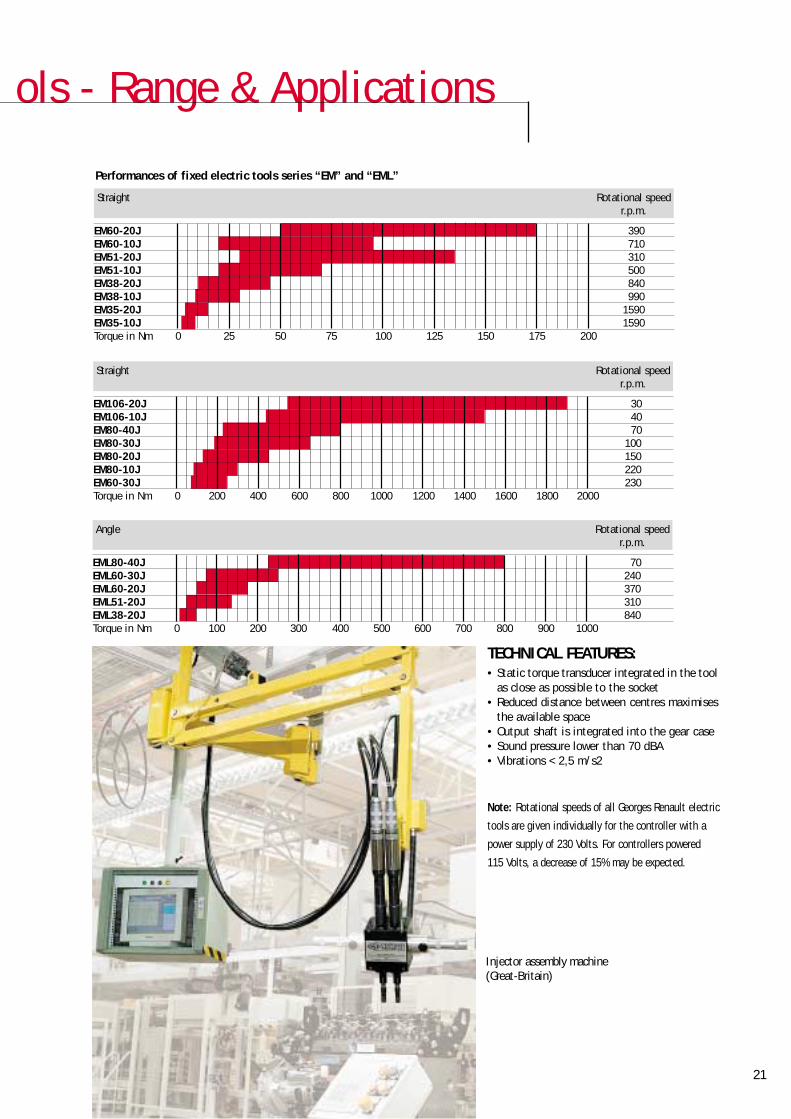
Performances of fixed electric tools series “EM” and “EML”
21
TECHNICAL FEATURES:• Static torque transducer integrated in the tool
as close as possible to the socket• Reduced distance between centres maximises
the available space• Output shaft is integrated into the gear case• Sound pressure lower than 70 dBA• Vibrations < 2,5 m/s2
Injector assembly machine(Great-Britain)
Straight Rotational speedr.p.m.
EM60-20J 390EM60-10J 710EM51-20J 310EM51-10J 500EM38-20J 840EM38-10J 990EM35-20J 1590EM35-10J 1590Torque in Nm 0 25 50 75 100 125 150 175 200
Straight Rotational speedr.p.m.
EM106-20J 30EM106-10J 40EM80-40J 70EM80-30J 100EM80-20J 150EM80-10J 220EM60-30J 230Torque in Nm 0 200 400 600 800 1000 1200 1400 1600 1800 2000
Angle Rotational speedr.p.m.
EML80-40J 70EML60-30J 240EML60-20J 370EML51-20J 310EML38-20J 840Torque in Nm 0 100 200 300 400 500 600 700 800 900 1000
Note: Rotational speeds of all Georges Renault electric
tools are given individually for the controller with a
power supply of 230 Volts. For controllers powered
115 Volts, a decrease of 15% may be expected.
22
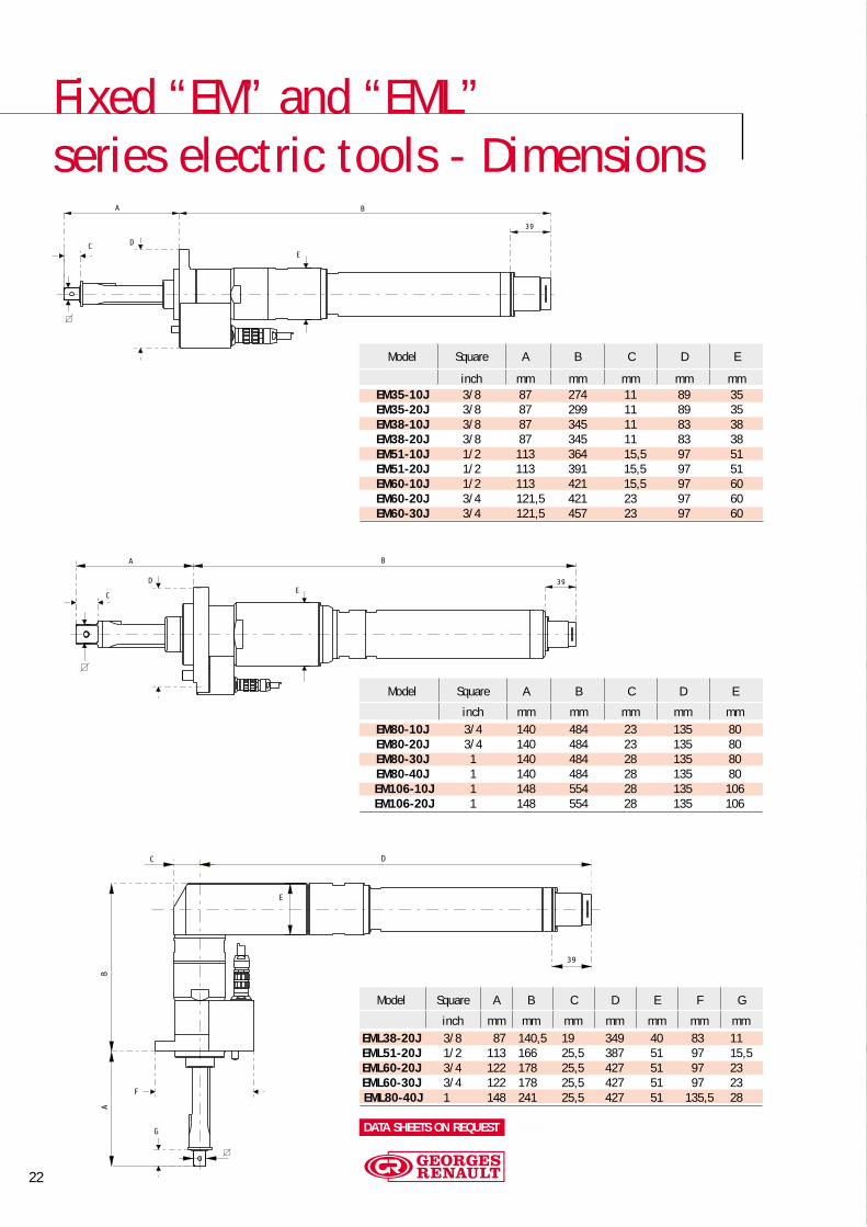
Fixed “EM” and “EML”series electric tools - Dimensions
Model Square A B C D E
inch mm mm mm mm mmEM35-10J 3/8 87 274 11 89 35EM35-20J 3/8 87 299 11 89 35EM38-10J 3/8 87 345 11 83 38EM38-20J 3/8 87 345 11 83 38EM51-10J 1/2 113 364 15,5 97 51EM51-20J 1/2 113 391 15,5 97 51EM60-10J 1/2 113 421 15,5 97 60EM60-20J 3/4 121,5 421 23 97 60EM60-30J 3/4 121,5 457 23 97 60
Model Square A B C D E
inch mm mm mm mm mmEM80-10J 3/4 140 484 23 135 80EM80-20J 3/4 140 484 23 135 80EM80-30J 1 140 484 28 135 80EM80-40J 1 140 484 28 135 80EM106-10J 1 148 554 28 135 106EM106-20J 1 148 554 28 135 106
Model Square A B C D E F G
inch mm mm mm mm mm mm mmEML38-20J 3/8 87 140,5 19 349 40 83 11EML51-20J 1/2 113 166 25,5 387 51 97 15,5EML60-20J 3/4 122 178 25,5 427 51 97 23EML60-30J 3/4 122 178 25,5 427 51 97 23EML80-40J 1 148 241 25,5 427 51 135,5 28
FICHES TECHNIQUES SUR DEMANDEDATA SHEETS ON REQUEST

23
Special applications, Cables & Accessories
OFFSET GEAR TO REDUCE THE DISTANCEOF THE SOCKETS
SPECIAL “HOLD AND DRIVE”SYSTEM FOR FIXED TOOLS.
90° “EM” MOTOR ADAPTORPART NO 615 396 118 0
90° CABLE CONNECTOR
STANDARD PART NOLENGTH TWINCVI MODCVI
5 m 615 917 132 0 615 917 142 010 m 615 917 134 0 615 917 144 015 m 615 917 135 0 615 917 145 020 m 615 917 136 0 615 917 146 025 m 615 917 137 0 615 917 147 030 m 615 917 138 0 615 917 148 035 m 615 917 139 0 615 917 149 0
STANDARD PART NOLENGTH TWINCVI MODCVI
Motor cable for EM tools0,7 m 615 917 091 05 m 615 917 092 0 615 917 112 0
10 m 615 917 094 0 615 917 114 015 m 615 917 095 0 615 917 115 020 m 615 917 096 0 615 917 116 025 m 615 917 097 0 615 917 117 030 m 615 917 098 0 615 917 118 035 m 615 917 099 0 615 917 119 0
Motor extension cable for EM tools5 m 615 917 162 0 615 917 182 0
10 m 615 917 164 0 615 917 184 015 m 615 917 165 0 615 917 185 020 m 615 917 166 0 615 917 186 025 m 615 917 167 0 615 917 187 030 m 615 917 168 0 615 917 188 035 m 615 917 169 0 615 917 189 0
Torque cable for EM tools1,5m 615 917 010 05 m 615 917 102 0 615 917 122 0
10 m 615 917 104 0 615 917 124 015 m 615 917 105 0 615 917 125 020 m 615 917 106 0 615 917 126 025 m 615 917 107 0 615 917 127 030 m 615 917 108 0 615 917 128 035 m 615 917 109 0 615 917 129 0
Torque extension cable for EM tools5 m 615 917 172 0 615 917 192 0
10 m 615 917 174 0 615 917 194 015 m 615 917 175 0 615 917 195 020 m 615 917 176 0 615 917 196 025 m 615 917 177 0 615 917 197 030 m 615 917 178 0 615 917 198 035 m 615 917 179 0 615 917 199 0
TRANSDUCER-HOLDER FROM EM TOOL PART NOWith 3/8” square drive 615 396 119 0With 1/2” square drive 615 396 120 0