Embed Size (px)
Citation preview

1
CVT Transients Revisited – Distance, Directional Overcurrent, and
Communications-Assisted Tripping Concerns
David Costello and Karl Zimmerman, Schweitzer Engineering Laboratories, Inc.
Abstract—Several classic papers explain the fundamentals of capacitive voltage transformer (CVT) design, operation, and transient response. Distance elements can overreach, particularly in high source-to-line impedance ratio (SIR) applications, which can result in undesired Zone 1 operations. Because this continues to be a problem in real applications, this paper revisits documented field cases using event data in hopes of shedding new light on this known problem. Solutions to distance element overreach are shared, from modified reach and time delays to modern solutions such as CVT transient detection logic.
How does the protection engineer know what type of CVT is used? How can the protection engineer calculate the SIR from real-world event data? This paper gives practical guidance for the user to answer these fundamental questions.
New data and research included in this paper update the topic. We investigate the CVT transient effect on directional element stability, directional overcurrent applications, and various communications-assisted protection schemes. We also share field cases of directional element and directional comparison blocking scheme misoperations and solutions and practical recommendations for mitigating the problems in all cases.
I. WHAT ARE THE CHARACTERISTICS OF CVTS?
Coupling capacitor voltage transformers or capacitive voltage transformers (CVTs) are commonly used throughout the high-voltage (HV) and extra-high-voltage (EHV) power system. The size and cost of wire-wound electromagnetic voltage transformers (VTs) are proportional to the voltage. While VTs reproduce primary voltages with excellent fidelity, the CVT is often more economical at higher voltages.
For faults that cause very depressed voltages, the CVT output voltage may not closely track the system voltage due to the internal CVT energy storage elements. In this section, we discuss the factors that affect CVT transient response.
A. Basic CVT Structure
The basic CVT structure without ferroresonance suppression is shown in Fig. 1 [1].
Coupling capacitors C1 and C2 function as a voltage divider. Most of the voltage is dropped across C1; a typical value for C1 in a 400 kV CVT is 104 pF. C2 is designed such that the voltage across it is typically 5 to 20 kV; a typical value for C2 in a 400 kV CVT is 2,000 pF. The compensating reactor, along with the magnetizing reactance of the step-down transformer, cancels or is resonant with the coupling capacitor at system frequency. This prevents phase shift between the primary and secondary voltages at system
frequency. The step-down transformer further reduces the voltage to a nominal voltage level, typically 66.4 V. The low voltage is applied across the CVT burden, protective relay, or meter.
Fig. 1. Basic CVT Structure
B. Physical Construction of CVTs
Series-connected capacitor elements are housed in sealed porcelain or composite insulator shells. The capacitor elements consist of aluminum foil, are insulated with a high-quality polypropylene film and paper insulation, and are filled with highly processed synthetic oil. Each CVT section includes an expansion chamber to allow the oil to expand and contract with changes in temperature. The tap voltage is taken from the lowest capacitor section and fed to the base of the unit. The base houses the compensating reactor, step-down transformer, and ferroresonance suppression circuitry.
A pressure relief mechanism is designed to relieve excessive pressure. Manufacturers boast of explosion-proof designs with new models. However, older CVTs that are aging have exploded and pose safety concerns, which are discussed later.
In addition to providing voltage to relays or meters, CVTs can couple high-frequency power line carrier signals onto the power line. CVTs can also reduce circuit breaker transient recovery voltage. Manufacturers produce some models that incorporate current transformers (CTs) and CVTs into a single unit.
C. Transient Response Waveform Examples
Relays rely on instrument transformers for valid information representing the power system voltages and currents. Fig. 2 shows a challenging case for a distance relay in 2011. As we will see, faults occurring at a zero voltage

2
produce large CVT errors and also produce fault currents with maximum offset. In this case, the CTs saturated and the line-side CVTs produced a transient response for a reverse three-phase bus fault. Though the directional element in the line relay correctly saw the bus fault as reverse initially, it then asserted forward briefly, causing the line relay to misoperate. In this case, the root cause was due to the CT saturation. Severe unbalance in the currents with near-zero negative-sequence voltage (V2) produced a negative-sequence impedance in the forward direction of the relay according to the relay settings. Simultaneous CT and CVT errors, therefore, are likely to occur.
Fig. 2. 138 kV CVT Transient With CT Saturation
Fig. 3 shows a line-to-ground fault on a 138 kV line with CVTs. Several interesting CVT characteristics can be observed. First, the faulted phase voltage experiences a transient at the fault inception. Second, the faulted phase experiences a second transient as the fault is cleared. Third, the unfaulted phase voltages from the CVT experience a transient after the fault is cleared and rise to a higher-than-nominal magnitude.
Fig. 3. 138 kV CVT Transient and Voltage Output Rise
CVTs experience a transient response after the line terminal opens. Fig. 4 shows a CVT ringdown following the opening of a ring-bus line terminal after a single-line-to-ground fault was cleared on a 138 kV line in 2008.
Fig. 4. 138 kV CVT Ringdown After Fault Clears and Terminal Opens
D. Factors That Affect the Transient Response of a CVT
The following six parameters determine the transient response of a CVT [2]:
• Point on the voltage wave when the fault occurs. • Magnitude of the tap and the stack capacitance (value
of C1 and C2 in Fig. 1). • Design of the ferroresonance suppression circuit
(active or passive). • Composition of the burden connected to the CVT. • Turns ratio of the step-down VT. • Excitation current of the intermediate transformer.
We briefly discuss these factors in this section, but further details can be obtained in [1], [2], [3], [4], and [5].
1) Point on the Voltage Wave at the Time of the Fault To fully understand this phenomenon, examine the CVT
equivalent circuit shown in Fig. 5. All the components are reflected to the high side of the step-up transformer.
Fig. 5. CVT Equivalent Circuit
The following definitions apply to Fig. 5:
EL is the intermediate or tap voltage. XCE is the Thévenin equivalent capacitance. XLC is the equivalent compensating reactance. XXFMR is the leakage inductive reactance of the step-down transformer. XM is the magnetizing reactance of the transformer. n2XS is the combined transformer capacitance and ferroresonance suppression reactance reflected to the high side. Ib + Im is the primary current. Im is the transformer excitation current. Ib is the burden current. n2ZB is the burden reflected to the high side. nEB is the output voltage.

3
Fig. 6 shows the relationship between the primary voltage (EL), the primary current (Ib + Im), and the voltages across XCE and n2ZB. With a resistive or unity power factor burden and with XL + XXFMR + XM = XCE at the nominal system frequency, the primary current (Ib + Im) is in phase with the primary voltage (EL). The voltage across the reactive components, however, is 90 degrees out of phase with the primary current.
nEBIb+Im
EL
ECE
Fig. 6. Phasor Relationship Between Components of a CVT
In essence, the energy stored in the compensating reactor is the same as the energy stored in the effective capacitance. The voltage and energy stored in the capacitor are at a maximum at a voltage zero crossing. The energy must be discharged at the time of the fault, and this produces the maximum transient voltage. The energy stored in the inductor is at a maximum at a voltage and primary current peak.
Because the amount of energy stored in the reactive components is the same, we examine the effect of the time constants.
Using the typical parameters from a 230 kV CVT, we can calculate the time constant of each element:
E
2C B En Z • C 30.644 millisecondsτ = = (1)
C
CL 2
B
L0.189 milliseconds
n Zτ = = (2)
where:
CE is the CVT equivalent capacitance, equal to 276.9 nF. LC is the CVT equivalent compensating reactance, equal to 20.954 H.
n2ZB is 110 kΩ. It is evident that the worst-case or longest transient
response occurs when the maximum energy is stored in the capacitor or when the primary voltage is at a zero crossing. We will see that the magnitude of the capacitance has a similar effect on transient duration. Fig. 7 and Fig. 8 show the outputs of a CVT for faults that occurred at voltage zero (zero crossing) and at voltage maximum, respectively [1].
Time (Cycle)
100
–100
80
–80
–60
–40
–20
0
20
40
60
–2 4–1 0 1 2 3
CVT Transient
Ratio Voltage
Fig. 7. CVT Response for a Fault at Voltage Zero (Zero Crossing)
Time (Cycle)
100
–100
80
–80
–60
–40
–20
0
20
40
60
–2 4–1 0 1 2 3
CVT Transient
Ratio Voltage
Fig. 8. CVT Response for a Fault at Voltage Maximum (Peak)
2) Magnitude of the Tap and the Stack Capacitance Again, we examine the CVT equivalent circuit shown in
Fig. 5. As CE becomes larger, the capacitive reactance becomes smaller.
CEE
1X
2• • f • C=
π (3)
If the burden remains the same, the primary current remains the same. The voltage drop across the equivalent capacitance is lower. The lower voltage results in a smaller discharge transient. However, note that increasing the value of CE increases the duration of the transient. Fig. 9 is a plot of the transient response of a normal-value and high-value capacitance CVT [1].
4
Time (Cycle)
10
0
9
1
2
3
4
5
6
7
8
1 41.5 2 2.5 3 3.5
High-Capacitance CVT
Normal-Capacitance CVT
Ratio Voltage
Fig. 9. High-Capacitance CVT Response More Closely Replicates Ratio Voltage
3) Ferroresonance Suppression Circuit All CVTs require ferroresonance damping. The capacitance
in the CVT in series with the inductance of the compensating reactor and transformer creates a possible oscillating or resonant circuit. The circuit can be brought to resonance by disturbances, such as voltage changes and transformer saturation.
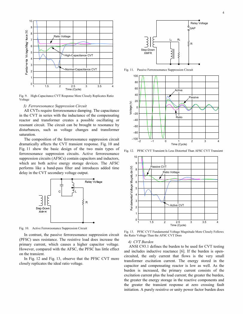
The composition of the ferroresonance suppression circuit dramatically affects the CVT transient response. Fig. 10 and Fig. 11 show the basic design of the two main types of ferroresonance suppression circuits. Active ferroresonance suppression circuits (AFSCs) contain capacitors and inductors, which are both active energy storage devices. The AFSC performs like a band-pass filter and introduces added time delay in the CVT secondary voltage output.
Fig. 10. Active Ferroresonance Suppression Circuit
In contrast, the passive ferroresonance suppression circuit (PFSC) uses resistance. The resistive load does increase the primary current, which causes a higher capacitor voltage. However, compared with the AFSC, the PFSC has little effect on the transient.
In Fig. 12 and Fig. 13, observe that the PFSC CVT more closely replicates the ideal ratio voltage.
Step-DownXMFR
Relay Voltage
Lf Rf
R
GAP
Fig. 11. Passive Ferroresonance Suppression Circuit
Time (Cycle)
100
–100
80
–80
–60
–40
–20
0
20
40
60
–2 4–1 0 1 2 3
Active
Ratio
Passive
Fig. 12. PFSC CVT Transient Is Less Distorted Than AFSC CVT Transient
Time (Cycle)
10
0
9
1
2
3
4
5
6
7
8
1 41.5 2 2.5 3 3.5
Passive CVT
Active CVT
Ratio Voltage
Fig. 13. PFSC CVT Fundamental Voltage Magnitude More Closely Follows the Ratio Voltage Than the AFSC CVT Does
4) CVT Burden ANSI C93.1 defines the burden to be used for CVT testing
and includes inductive reactance [6]. If the burden is open-circuited, the only current that flows is the very small transformer excitation current. The energy stored in the capacitor and compensating reactor is low as well. As the burden is increased, the primary current consists of the excitation current plus the load current; the greater the burden, the greater the energy storage in the reactive components and the greater the transient response at zero crossing fault initiation. A purely resistive or unity power factor burden does

5
not store energy, but it does affect damping and the time constant. If inductive reactance is added to the burden and the burden power factor decreases, the transient response worsens and becomes oscillatory at a subnominal frequency.
For modern applications, consider the burden for microprocessor-based relays to be two to three orders of magnitude smaller in VA (larger in ohms) than the ANSI burden and almost entirely resistive.
5) Turns Ratio and Excitation Current A higher turns ratio in the step-down transformer decreases
the primary current by magnifying the burden. The smaller the current, the less energy is stored in the capacitor. From the perspective of the burden, the capacitance and inductance can be reflected to the secondary by the inverse of the turns ratio squared. Transformers with larger turns ratios (e.g., 15 kV to 20 kV/66.4 V) produce transients of lesser magnitude but longer duration. As mentioned previously, as the primary current is at nonunity power factor, subnominal frequency oscillations can occur and larger primary currents produce greater transients. Therefore, transformers are designed to minimize excitation current.
II. ZONE 1 OVERREACH DUE TO CVT TRANSIENTS
As Fig. 9 shows, CVT transients can reduce the fundamental component of the fault voltage presented to relays. This decreased fundamental voltage results in a decreased calculated impedance in distance and directional relays. In addition, the transient response results in a spiraling or oscillation in the calculated impedance. If the reduction of calculated impedance is great enough, instantaneous Zone 1 distance elements may undesirably overreach for out-of-section faults. Fig. 14 shows the results of two fault simulations. In both cases, the relay observes a trajectory of calculated impedance from prefault load to the actual fault location. In the presence of a severe CVT transient, the calculated impedance comes within the Zone 1 distance element reach and causes a misoperation.
Fig. 14. CG Fault Produces CVT Transient and Zone 1 Overreach
In 2002, a 230 kV transmission line experienced a C-phase-to-ground (CG) fault. The fault inception was at a voltage maximum. The local relay tripped by the Zone 1
ground distance element for a fault that was physically located beyond the Zone 1 reach setting [7] [8]. The unfiltered event data from this misoperation are shown in Fig. 15. The CVT used AFSC.
Fig. 15. CG Fault Produces CVT Transient
The event shows a severe transient in the C-phase voltage just before the Zone 1 distance element operation. This transient makes the C-phase voltage magnitude appear smaller to the relay than the actual ratio voltage, which makes the apparent impedance calculated by the relay appear smaller, or closer to the local terminal, than actual. The CG distance element asserted for less than 1 cycle. When the fault clears, the C-phase voltage has another transient that makes it appear higher in magnitude than the other phases.
In these applications, there are several practical mitigation strategies that are easy to implement with existing protection. Of course, the Zone 1 element may be disabled; however, in most applications, this is not ideal, and in many, it is not acceptable. The Zone 1 element could then be reduced in reach, or the Zone 1 element could be delayed slightly (1.5 cycles).
The curves in Fig. 16 show the maximum allowed Zone 1 reach setting at various source-to-line impedance ratios (SIRs). The results shown are the worst-case distance element overreach—faults with a point-on-wave inception that occur at a voltage zero. A distance relay transient response for a CVT with a PFSC is much better because the relay has much less overreach. When using a CVT with a PFSC, the need to restrict the Zone 1 distance element reach is greatly reduced.
As discussed previously, a major factor that affects the severity of CVT transients is the fault voltage magnitude level. The smaller the fault voltage level, the more prolonged and distorted the CVT transient. Of course, the user has no control over the point-on-wave at which the fault begins. However, the SIR directly influences the fault voltage level for a fault at a given location. Fig. 16 shows that when used with the CVT having an AFSC, the Zone 1 element of the distance relay set to 80 percent of the protected line impedance can tolerate CVT transients for systems with SIRs only up to 4. If the SIR is larger than 4, the reach must be

6
reduced. Further, without any additional logic, the relay Zone 1 protection must be eliminated completely for systems with SIRs greater than or equal to 20. The relay transient response when using a CVT with a PFSC is much better; a generic 80 percent Zone 1 reach is effective for SIRs as high as 30.
Fig. 16. Maximum Secure Zone 1 Reach Without CVT Detection Logic
Equation (4) and the data from the event in Fig. 15 allow us to calculate the SIR for this application. The positive-sequence voltage (V1) and positive-sequence current (I1) phasors are read from the fault and prefault sections of the event data. Care must be taken to read the phasors from the same sample points within the power system cycles. Alternatively, use negative-sequence quantities during the fault to calculate the SIR.
FAULT PREFAULT
FAULT PREFAULT LINE
V1 V1SIR
(I1 I1 ) • Z1
−=
− (4)
The positive-sequence source impedance for this application is 11 ohms secondary, and the line impedance is 0.59 ohms secondary, giving an SIR of more than 18. For an SIR of 18 and a CVT with AFSC, the maximum secure Zone 1 reach is 7 percent of the line. For such a small line impedance or short line, this results in a required or secure Zone 1 setting that is below the minimum range allowed by this relay (0.05 ohms secondary). Thus, in this application, Zone 1 had to be disabled in the existing relay.
As mentioned previously, the CVT transient severity is also affected by the burden of the magnitude and angle of the connected load. Fig. 17 shows the maximum Zone 1 reach setting as a function of different burdens for the CVT with a PFSC. Resistive burdens dampen the CVT transient, and therefore, the distance element reach does not have to be reduced as much. When using a CVT, engineers need to calculate the total burden of all the devices connected on the CVT and make sure the burden is small and nearly resistive to ensure proper distance relay protection. Microprocessor-based relays have very small and nearly resistive input burdens. In the event in Fig. 15, the relay was already a microprocessor-based design.
Another mitigation strategy that is easy to implement with existing distance relays with multiple zones of protection is to split Zone 1 into two sections (see Fig. 18). The first section has a reduced reach (determined using the information in Fig. 16 and Fig. 17) and is allowed to trip instantaneously. The second section is set to the desired or normal Zone 1 reach but with a time delay of 1.5 cycles. This is a slightly more complex solution, but it provides fast tripping for close-in faults and takes advantage of the multiple zones available in relays to add security for end-of-line faults.
Max
imum
Zon
e 1
Rea
ch S
etti
ng (
pu)
Fig. 17. Maximum Zone 1 Reach With Different Burdens Using PFSC CVT
Fig. 18. Improved Zone 1 Settings Strategy
Modern relays include CVT transient detection logic, as shown in Fig. 19. This logic detects a CVT transient and, when enabled, blocks the Zone 1 distance tripping for up to 1.5 cycles. The time delay is reduced or eliminated if the distance calculation smoothes, indicating the transient has subsided. CVT transient detection logic eliminates distance element overreach due to CVT transients, with the minimal tradeoff of a short time delay for true in-zone faults. The logic requires no special user settings and adapts to different SIRs.
Fig. 19. CVT Transient Detection Logic Available in Modern Distance Relays
In 2009, a 7-mile-long 161 kV transmission line using CVTs experienced an overreach of the Zone 1 distance element for a remote bus fault. The Zone 1 element was set to 90 percent of the line impedance. The unfiltered event data are shown in Fig. 20.

7
Fig. 20. Unfiltered Event Data Show CVT Transient and Zone 1 Distance Overreach With CVT Detection Disabled
Fig. 21 shows a Mathcad® worksheet that calculates and plots the impedance calculation of the relay. The AB impedance loop plots within Zone 1 for less than 1 cycle. However, this caused the overreach and trip.
Fig. 21. Zone 1 Impedance Calculation Asserts for Less Than 1 Cycle
Rather than reduce the Zone 1 reach, add a time delay, or use a multizone approach as previously discussed, we evaluate the modern CVT transient detection logic performance. The real-world event data were converted to an IEEE COMTRADE file and replayed into a relay in the laboratory with CVT transient detection logic enabled. The data shown are digitally filtered in Fig. 22. The CVT transient detection logic asserts, preventing the Zone 1 element overreach.
If a modern relay includes CVT transient detection logic and is applied in a line protection application with CVTs, enable the logic for better security.
Fig. 22. Zone 1 Distance Element Is Secure and Does Not Overreach Due to CVT Transient Detection Logic
III. IMPACT OF CVT TRANSIENTS ON DIRECTIONAL ELEMENTS
The impact of CVT transients on distance elements is fairly well known and understood. However, there have been two
unusual operations of directional elements due to CVT transients that bear further investigation.
The directional element under study calculates the magnitude of the negative-sequence impedance that lies collinearly to the protected positive-sequence line impedance [9].
[ ]2 2
2measured 22
Re V • (1 Z1ANG • I )*Z
I
∠= (5)
where:
V2 is the negative-sequence voltage. I2 is the negative-sequence current. ∠Z1ANG is the positive-sequence line angle. * indicates the complex conjugate.
By comparing Z2measured to thresholds, this element yields the fault direction. The thresholds are determined by user settings and the measured system voltages and currents. If Z2measured is less than the forward threshold Z2F, the fault is declared forward. If Z2measured is greater than the reverse threshold Z2R, the fault is declared reverse.
A simple system is shown in Fig. 23 and Fig. 24.
Fig. 23. Simple System Shown With Sequence Networks
+ϕL2Z Angle
Fig. 24. Measured Negative-Sequence Impedance Yields Fault Direction

8
Fig. 25 shows an unfiltered event on a 345 kV line where a reverse AG fault occurred on an adjacent line during an ice storm. In this case, a directional element incorrectly asserts forward (32QF) and then correctly asserts reverse (32QR). Observe how the unfaulted phase voltages go high and, especially in C-phase, the voltage overshoots during the transient before settling on its faulted value.
Fig. 25. Unfiltered Event Shows Reverse AG Fault Picks Up Forward, Then Reverse
Because the relay responds to filtered quantities, the resultant directional element response is shown in Fig. 26. This figure shows a Mathcad plot of Z2measured (Z2i) compared to the forward and reverse thresholds (ZFthrei and ZRthrei, respectively).
Fig. 26. Mathcad Model Confirms Z2 Erratic Behavior During CVT Transient
What caused the unfaulted C-phase voltage to overshoot so severely? Among the possible root causes are the following:
• A problem in the power system grounding could have caused the unfaulted phase voltages to go as high as 1.732 times the nominal phase-to-ground voltage (ungrounded system). The event shows that the unfaulted voltages are about 110 percent of nominal after the transient.
• A problem in the CVT secondary grounding circuit (i.e., ungrounded or multiple grounds on the VTs) could have produced an erroneous response. This was investigated, and no anomalies were found.
• The CVT itself could have an internal problem. In this case, the CVT was a low-capacitance AFSC CVT.
Another similar event occurred on a 161 kV line. In this case, a reverse CG fault incorrectly asserted forward during the initial transient. Fig. 27 and Fig. 28 show a screen capture and Mathcad model of the event.
Fig. 27. Unfiltered COMTRADE Shows Reverse CG Fault Picks Up Forward, Then Reverse
10
0
9.98
8–10
10.0
05
10.0
21
10.0
38
10.0
55
10.0
71
10.0
88
10.1
05
10.1
21
10.1
38
10.1
559.
971
5
–5
Z2Rthrei
Z2Fthrei
Z2i
Time (sec)
Ohm
s (s
ec)
Fig. 28. Mathcad Model Confirms Event Report
This event was also measured by an independent relay, which captured the unfiltered voltages of the CVT and a 69 kV conventional VT that sensed the same event, as seen in Fig. 29. We can see the unfaulted CVT B-phase voltage experienced a significant transient.
Fig. 29. CVT and Conventional VT Waveforms for CG Fault
CVT
CVT
Faulted C-Phase Voltages
Unfaulted B-Phase Voltages
CVT
Unfaulted A-Phase Voltages
9
The CVT make and model are the same as for the previous case shown in Fig. 25: a low-capacitance, AFSC-based design. The CVT instruction manual contains this recommendation:
When high speed directional relays are energized from this device it is recommended that the basic burden be power factor corrected to 100% or slightly leading, and that the device be loaded to its full rating of 150 watts, by the addition of parallel resistance if necessary. The purpose of this is to reduce to a minimum the possibility of incorrect relay operation which might result from device output transients following an extremely close-up system short circuit. An excess of 13 var on a fully loaded device will give a 5° leading angle. [10]
Based on this statement, the transient effect on directional elements is a known problem, and the manufacturer has made recommendations to mitigate the effect of the transient. These recommendations indicate that increasing the resistive burden in VA (reducing in ohms) would dissipate the transient more quickly for the AFSC CVT design.
Although it is clear that the two cases discussed in this section are rare, they spurred interest in how negative-sequence (Z2) directional elements perform in the presence of CVT transients. Using a Real Time Digital Simulator (RTDS®), we ran dozens of fault scenarios, with and without CVTs, for strong and weak sources, with and without series compensation, and various fault types.
In general, the directional elements perform as expected and correctly. Fig. 30 and Fig. 31 show the correct performance of the directional elements for a simulated forward AG fault on a line with shunt capacitance and a weak source, with and without CVTs.
One noteworthy discovery from Fig. 30 and Fig. 31 is the duration of the voltage decay after the fault is cleared. Because CVTs are shunt devices, it is not surprising that the voltage decay takes longer on lines with CVTs compared with those with VTs. This is of interest when performing reclosing on a line, as described in the next section.
Fig. 30. Directional Element Asserts Forward for AG Fault With CVTs
Fig. 31. Directional Element Asserts Forward for AG Fault With Conventional VTs
IV. IMPACT OF CVT TRANSIENTS ON RECLOSING
How do CVT transients have an impact on reclosing? Recall the ringdown in Fig. 4.
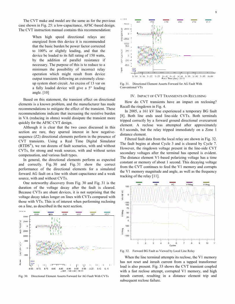
In 2005, a 161 kV line experienced a temporary BG fault [8]. Both line ends used line-side CVTs. Both terminals tripped correctly by a forward ground directional overcurrent element. A reclose was attempted after approximately 0.5 seconds, but the relay tripped immediately on a Zone 1 distance element.
Filtered fault data from the local relay are shown in Fig. 32. The fault begins at about Cycle 3 and is cleared by Cycle 7. However, the ringdown voltage present in the line-side CVT secondary voltages after the terminal has opened is evident. The distance element V1-based polarizing voltage has a time constant or memory of about 1 second. This decaying voltage from the CVT continues to feed the V1 memory and corrupts the V1 memory magnitude and angle, as well as the frequency tracking of the relay [11].
-100
0
100
0
25
50
75
100
-100
0
100
1 2 3 4 5 6 7 8 9 10 11
VA
VB
VC
V1
Ma
gV
1A
ng
Cycles
VA VB VC V1Mag V1Ang
Fig. 32. Forward BG Fault as Viewed by Local Line Relay
When the line terminal attempts its reclose, the V1 memory has not reset and inrush current from a tapped transformer load is also present. Fig. 33 shows the CVT transient coupled with a fast reclose attempt, corrupted V1 memory, and high inrush current, resulting in a distance element trip and subsequent reclose failure.

10
ZAB 3 1 1 1 1 1 1 1
-2500
0
2500
0
1000
2000
-100
0
100
0 1 2 3 4 5 6 7 8 9 10 11 12
IA IB
IC
IAM
ag
IB
Ma
g I
CM
ag
VA
VB
VC
Dig
itals
Cycles
IA IB IC IAMag IBMag
ICMag VA VB VC
Fig. 33. Raw Data From Local Relay During Reclose
Event data from the reclose were converted to IEEE COMTRADE format and replayed into a similar relay in the laboratory. With no influence from the corrupted V1 memory, as was the case in the real event in the field, the Zone 1 distance element did not trip (see Fig. 34). This is because the V1 memory was reset at the time the test was started and a fast recharge circuit instructed the relay to use the actual measured V1.
ZAB
-2000
-1000
0
1000
2000
-100
-50
0
50
100
0 1 2 3 4 5 6 7 8 9 10 11 12
IA I
B I
CV
A V
B V
CD
igita
ls
Cycles
IA IB IC VA VB VC
Fig. 34. IEEE COMTRADE Replay of Event Data With V1 Memory Reset
Reclose open intervals must take into account CVT transient response and decay and V1 memory in relays. Fault detectors that supervise distance elements should be set above transformer inrush currents [12]. If advanced distance element features are available, shorter reclose intervals can be used. These features include adjusting the time constant of the memory to a value approaching zero or substituting zeros into the memory filter when ringdown voltage or a terminal-open condition is detected [11].
V. IMPACT OF CVT TRANSIENTS ON
COMMUNICATIONS-ASSISTED TRIPPING SCHEMES
How do CVT transients affect communications-assisted tripping schemes?
The event described in Fig. 35, Fig. 36, and Fig. 37 shows a directional element that initially declares forward for a reverse fault. This is the same event described in Section III
(Fig. 25). Fig. 35 shows a 345 kV line protected using a directional comparison blocking (DCB) scheme. In this case, the relay at Substation K tripped before receiving the block signal from Substation L.
In Fig. 37, the relay at Substation K overtrips by the directional ground element. The carrier coordination delay in this application was set to 1.5 cycles. The delayed directional carrier start and the channel delay exceeded 1.5 cycles.
Fig. 35. One-Line Diagram of 345 kV Line Protected Using a DCB Scheme
Fig. 36. CVT Transient Causes Delay in Sending Block Signal (OUT7/67N3) From Substation L
Fig. 37. Substation K Relay Overtrips (67N2) Due to Delayed Block Signal Input (IN9)

11
A. Directional Comparison Blocking
Distance element overreach caused by CVT transients poses no risk to DCB schemes. Additionally, both distance and ground directional overcurrent elements are generally directionally stable.
The case described in this section was a direct result of the particular AFSC CVT design. In general, it is best to upgrade CVTs when possible. However, sometimes the protection engineer has to adapt and overcome, so if replacing the CVT is not an option, consider using longer carrier coordination delays to ride through the transient.
B. Permissive Underreaching or Overreaching Transfer Trip (PUTT/POTT)
PUTT schemes use underreaching tripping elements to send permissive signals. Reduce Zone 1 distance reach, or use CVT detection logic to increase security when applying with CVTs.
Cautions similar to those described in the DCB scheme subsection apply to POTT. If the AFSC CVT design is applied, consider adding a pickup delay to the transmitted permissive trip signal.
VI. MONITORING AGING CVTS TO AVOID CATASTROPHIC FAILURES
Aging CVT components can degrade, resulting in secondary voltages losing accuracy and progressively degrading. Eventually, the capacitors may fail and cause a protection system failure. A greater concern to safety is the possibility of a catastrophic failure of the CVT if a sufficient number of capacitor elements fail, arc, and explode. CVT explosions can rupture the porcelain shell and metallic base and propel fragments and hot synthetic oil over a large area within the substation yard [13]. Fig. 38 shows the physical destruction following the catastrophic failure of a high-voltage CVT. To improve safety for personnel, CVTs should be monitored continuously.
Fig. 38. Debris Scattered Throughout Substation Following a Catastrophic CVT Failure
The North American Electric Reliability Corporation (NERC) draft standard PRC-005-2 details the requirements for protection system maintenance and testing. It mandates a minimum interval for testing monitored equipment and clarifies what must be tested based on what is monitored continuously. Reference [14] explains how to automate metering comparisons between primary and alternate line relays and alarm when differences in magnitude or angle indicate a problem. The benefit of this approach is that the user no longer needs to periodically verify through secondary injection tests that the analog inputs of one relay are measuring within an acceptable range. The measurements are continuously verified by comparison to an independent source, with alarming for excessive error. Using synchrophasor measurements ensures time-alignment and extreme accuracy.
This same approach can be used to qualify the accuracy of CVT measurements within a substation. For example, in a ring-bus or breaker-and-half substation with all breakers closed, all of the line terminal phase CVT measurements should match in magnitude and angle. Differences can be detected immediately, alarms can be generated for improved personnel safety, and suspect equipment can be de-energized and tested.
VII. CONCLUSION
The following points summarize CVT considerations: • CVT transients are larger for zero-voltage point-on-
wave faults, low CVT capacitance, AFSCs, high SIRs, low transformer ratios, high transformer excitation current, and inductive and larger burdens (in VA).
• CVT transients are lower for peak voltage point-on-wave faults, higher CVT capacitance, PFSCs, low SIRs, higher transformer ratios, low excitation current, and resistive and low burdens (in VA).
• For older relays, CVT-caused Zone 1 distance element overreach solutions include disabling Zone 1, time-delaying Zone 1, or restricting Zone 1 reach per the guidelines based on burden, SIR, and ferroresonance suppression design.
• For newer relays, enable CVT transient detection logic for secure Zone 1 distance element operation.
• Directional elements are generally secure for CVT transients, although this paper describes two field cases that showed exceptions to this rule.
• CVT transients can be detrimental to high-speed reclosing, especially with distance elements using memory polarization and tapped loads with inrush. Extending reclose open intervals and setting fault detectors above load are practical solutions for existing applications.

12
• Adjusting the time constant of the memory voltage to a value approaching zero or substituting zeros into the memory filter when ringdown voltage or a terminal-open condition is detected are additional solutions to high-speed reclosing problems.
• CVT transients generally do not pose a risk to DCB or POTT schemes. When certain older AFSC CVT designs are applied, adhere to the specific burden requirements of the CVT manufacturer. When using those designs, consider using extended carrier coordination delays for DCB schemes and delayed transmission of permissive signals for POTT schemes.
• Older and aging CVTs can fail and explode violently. Use synchrophasors and automated metering checks to extend maintenance intervals and, more importantly, improve personnel safety.
VIII. ACKNOWLEDGMENT
The authors gratefully acknowledge the contributions of Normann Fischer for his work on this paper.
The authors also gratefully acknowledge the contributions of Ryan McDaniel, Daqing Hou, and Jordan Bell for their assistance in the research phase of this paper.
IX. REFERENCES [1] D. Hou and J. Roberts, “Capacitive Voltage Transformers: Transient
Overreach Concerns and Solutions for Distance Relaying,” proceedings of the 22nd Annual Western Protective Relay Conference, Spokane, WA, October 1995.
[2] A. Sweetana, “Transient Response Characteristics of Capacitive Potential Devices,” IEEE Transactions on Power Apparatus and Systems, Vol. PAS-90, No. 5, September 1971, pp.1989–2001.
[3] D. Tziouvaras, J. Roberts, G. Benmouyal, and D. Hou, “The Effect of Conventional Instrument Transformer Transients on Numerical Relay Elements,” proceedings of the 28th Annual Western Protective Relay Conference, Spokane, WA, October 2001.
[4] D. Angell and D. Hou, “Input Source Error Concerns for Protective Relays,” proceedings of the 33rd Annual Western Protective Relay Conference, Spokane, WA, October 2006.
[5] W. A. Elmore, Protective Relaying Theory and Applications, ABB Power T&D Company Inc., Coral Springs, FL, 2004.
[6] ANSI C93.1-1999, American National Standard Requirements for Power-Line Carrier Coupling Capacitors and Coupling Capacitor Voltage Transformers (CCVT), 1999.
[7] G. A. Franklin and R. Horton, “Determining Distance Relay Zone-1 Reach Settings to Prevent CCVT Transient Overreach,” proceedings of the IEEE SoutheastCon 2011, Nashville, TN, March 2011.
[8] D. Costello, “Lessons Learned Analyzing Transmission Faults,” proceedings of the 34th Annual Western Protective Relay Conference, Spokane, WA, October 2007.
[9] K. Zimmerman and D. Costello, “Fundamentals and Improvements for Directional Relays,” proceedings of the 63rd Annual Conference for Protective Relay Engineers, College Station, TX, March 2010.
[10] Westinghouse Electric Corporation, Coupling Capacitor Potential Devices, Types PCA-3 & PCA-4, I.B. 49-610-2, December 1957.
[11] D. Costello and K. Zimmerman, “Frequency Tracking Fundamentals, Challenges, and Solutions,” proceedings of the 64th Annual Conference for Protective Relay Engineers, College Station, TX, April 2011.
[12] J. Mooney and S. Samineni, “Distance Relay Response to Transformer Energization: Problems and Solutions,” proceedings of the 60th Annual Conference for Protective Relay Engineers, College Station, TX, March 2007.
[13] B. Kasztenny and I. Stevens, “Monitoring Ageing CCVTs: Practical Solutions With Modern Relays to Avoid Catastrophic Failures,” proceedings of the Power Systems Conference, Clemson, SC, March 2007.
[14] A. Amberg, “Continuous Maintenance Testing With Automatic Meter Comparisons,” SEL Application Guide (AG2011-03), February 2011. Available: http://www.selinc.com.
X. BIOGRAPHIES David Costello graduated from Texas A&M University in 1991 with a BSEE. He worked as a system protection engineer at Central Power and Light and Central and Southwest Services in Texas and Oklahoma. He has served on the System Protection Task Force for ERCOT. In 1996, David joined Schweitzer Engineering Laboratories, Inc., where he has served as a field application engineer and regional service manager. He presently holds the title of senior application engineer and works in Fair Oaks Ranch, Texas. He is a senior member of IEEE, a member of the planning committee for the Conference for Protective Relay Engineers at Texas A&M University, and a recipient of the 2008 Walter A. Elmore Best Paper Award from the Georgia Institute of Technology Protective Relaying Conference.
Karl Zimmerman is a senior power engineer with Schweitzer Engineering Laboratories, Inc. in Fairview Heights, Illinois. His work includes providing application and product support and technical training for protective relay users. He is a senior member of the IEEE Power System Relaying Committee and chairman of Working Group D25, Distance Element Response to Distorted Waveforms. Karl received his BSEE degree at the University of Illinois at Urbana-Champaign and has over 20 years of experience in the area of system protection. He has authored over 25 papers and application guides on protective relaying and was honored to receive the 2008 Walter A. Elmore Best Paper Award from the Georgia Institute of Technology Protective Relaying Conference.
Previously presented at the 2012 Texas A&M Conference for Protective Relay Engineers.
© 2012 IEEE – All rights reserved. 20120217 • TP6556-01