Embed Size (px)
Citation preview
Carling Technologies, Inc.60 Johnson Avenue, Plainville, CT 06062Email: [email protected] Support: [email protected]: 860.793.9281 Fax: 860.793.9231
www.carlingtech.com
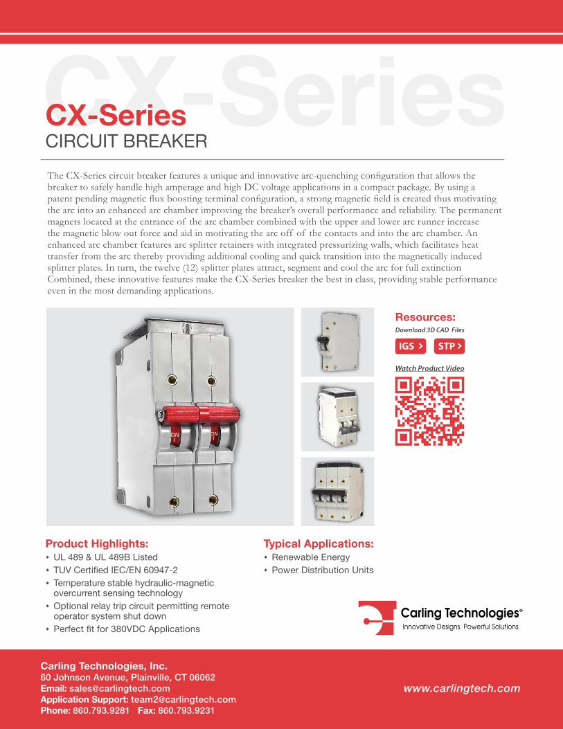
CX-SeriesCX-SeriesCIRCUIT BREAKERThe CX-Series circuit breaker features a unique and innovative arc-quenching configuration that allows the breaker to safely handle high amperage and high DC voltage applications in a compact package. By using a patent pending magnetic flux boosting terminal configuration, a strong magnetic field is created thus motivating the arc into an enhanced arc chamber improving the breaker’s overall performance and reliability. The permanent magnets located at the entrance of the arc chamber combined with the upper and lower arc runner increase the magnetic blow out force and aid in motivating the arc off of the contacts and into the arc chamber. An enhanced arc chamber features arc splitter retainers with integrated pressurizing walls, which facilitates heat transfer from the arc thereby providing additional cooling and quick transition into the magnetically induced splitter plates. In turn, the twelve (12) splitter plates attract, segment and cool the arc for full extinction Combined, these innovative features make the CX-Series breaker the best in class, providing stable performance even in the most demanding applications.
Product Highlights: � UL 489 & UL 489B Listed � TUV Certified IEC/EN 60947-2 � Temperature stable hydraulic-magnetic overcurrent sensing technology
� Optional relay trip circuit permitting remote operator system shut down
� Perfect fit for 380VDC Applications
Typical Applications: � Renewable Energy � Power Distribution Units
Resources:Download 3D CAD Files
IGS STP
Watch Product Video
Email: [email protected] Application Support: [email protected] Phone: (860) 793–9281 Fax: (860) 793–9231 www.carlingtech.com
2 | CX-Series Circuit Breaker - Design Features
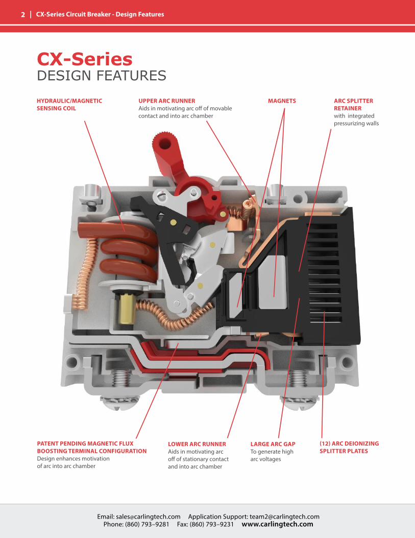
UPPER ARC RUNNER Aids in motivating arc off of movable contact and into arc chamber
PATENT PENDING MAGNETIC FLUX BOOSTING TERMINAL CONFIGURATION Design enhances motivation of arc into arc chamber
HYDRAULIC/MAGNETICSENSING COIL
ARC SPLITTER RETAINERwith integrated pressurizing walls
LOWER ARC RUNNERAids in motivating arc off of stationary contact and into arc chamber
LARGE ARC GAPTo generate high arc voltages
(12) ARC DEIONIZINGSPLITTER PLATES
MAGNETS
CX-SeriesDESIGN FEATURES
Email: [email protected] Application Support: [email protected] Phone: (860) 793–9281 Fax: (860) 793–9231 www.carlingtech.com
Email: [email protected] Application Support: [email protected] Phone: (860) 793–9281 Fax: (860) 793–9231 www.carlingtech.com
| 3 CX-Series Circuit Breaker - General Specifications
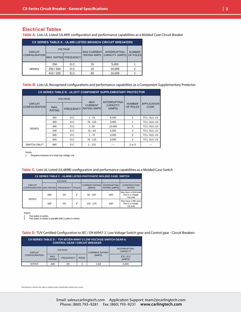
Electrical TablesTable A: Lists UL Listed (UL489) configuration and performance capabilities as a Molded Case Circuit Breaker
Table C: Lists UL Listed (UL489B) configuration and performance capabilities as a Molded Case Switch
Table D: TUV Certified Configuration to IEC / EN 60947-2. Low Voltage Switch gear and Control gear - Circuit Breakers
Table B: Lists UL Recognized configurations and performance capabilities as a Component Supplementary Protector
600 DC 2 1 50 - 100 600May have a third pole
that is a voltage trip pole
600 DC 4 2 110 - 175 600May have a fifth pole
that is a voltage trip pole
SERIES
MAX RATING
CX SERIES TABLE C : UL489B LISTED PHOTOVATIC MOLDED CASE SWITCH
CONSTRUCTION NOTES
VOLTAGE
INTERRUPTING RATING (AMPS)
CURRENT RATING (AMPS)FREQUENCY POLES
CIRCUIT CONFIGURATION
SERIES 440 DC 1-63 4,000
CX-SERIES TABLE D : TUV IEC/EN 60947-2 LOW VOLTAGE SWITCH GEAR & CONTROL GEAR / CIRCUIT BREAKER
VOLTAGE
FREQUENCY
CIRCUIT CONFIGURATION
MAX. RATING
INTERRUPTINGCAPACITY
ICS / ICU(AMPS)
CURRENT RATING(AMPS)
POLES
2
250 D.C. 15 5,000 1
250 / 500 D.C. 15 10,000 2
410 / 205 D.C. 50 10,000 2
SERIES
CX SERIES TABLE A : UL489 LISTED BRANCH CIRCUIT BREAKERS
VOLTAGENUMBER
OF POLESMAX. RATING FREQUENCY
CIRCUIT CONFIGURATION
MAX CURRENT RATING AMPS
INTERRUPTING CAPACITY (AMPS)
300 D.C. 1 - 75 5,000 1 TC1, OL0, U3
300 D.C. 76 - 125 3,000 1 TC1, OL0, U3
440 D.C. 1 -30 10,000 2 TC1, OL0, U3
440 D.C. 31 - 63 5,000 2 TC1, OL0, U3
600 D.C. 1 - 75 5,000 2 TC1, OL0, U3
600 D.C. 76 - 115 3,000 2 TC1, OL0, U3
SWITCH ONLY1 600 D.C. 1 - 115 ---- 2 or 3 ---
SERIES
CX SERIES TABLE B : UL1077 COMPONENT SUPPLEMENTARY PROTECTOR
APPLICATION CODE
VOLTAGE
NUMBER OF POLESMAX.
RATINGFREQUENCY
CIRCUIT CONFIGURATION
MAX CURRENT
RATING AMPS
INTERRUPTING CAPACITY
(AMPS)
Notes: 1 Two poles in series.2 Two poles in series in parallel with 2 poles in series.
Notes: 1 Requires inclusion of a relay trip voltage coil
*Manufacturer reserves the right to change product specification without prior notice.
Email: [email protected] Application Support: [email protected] Phone: (860) 793–9281 Fax: (860) 793–9231 www.carlingtech.com
4 | CX-Series Circuit Breaker - General Specifications
OHMS
0.1
1
10
100
1 100100.001
0.01
0.10.01
1000
AMPERE RATING
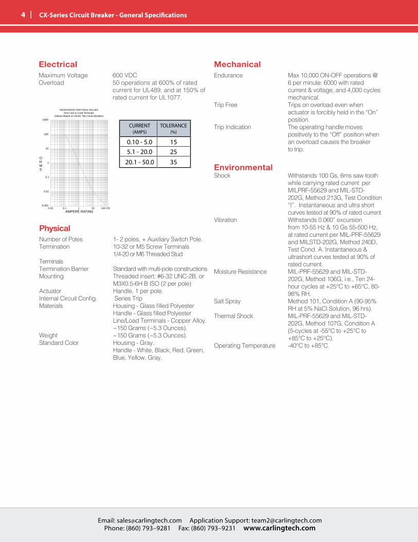
RESISTANCE, IMPEDANCE VALUESfrom Line to Load Terminals
(Values Based on Series Trip Circuit Breaker) Current(amps)
Tolerance(%)
0.1 -5.0 15%5.1-20.0 25%20.1-125 35%
RESISTANCE PER POLE VALUESfrom Line to Load Terminals
(Values Based on Series Trip Circuit Breaker)
100-125
ElectricalMaximum Voltage 600 VDCOverload 50 operations at 600% of rated current for UL489, and at 150% of rated current for UL1077.
MechanicalEndurance Max 10,000 ON-OFF operations @ 6 per minute; 6000 with rated current & voltage, and 4,000 cycles mechanical.Trip Free Trips on overload even when actuator is forcibly held in the “On” position.Trip Indication The operating handle moves positively to the “Off” position when an overload causes the breaker to trip.
EnvironmentalShock Withstands 100 Gs, 6ms saw tooth while carrying rated current per MILPRF-55629 and MIL-STD- 202G, Method 213G, Test Condition “I”. Instantaneous and ultra short curves tested at 90% of rated currentVibration Withstands 0.060” excursion from 10-55 Hz & 10 Gs 55-500 Hz, at rated current per MIL-PRF-55629 and MILSTD-202G, Method 240D, Test Cond. A. Instantaneous & ultrashort curves tested at 90% of rated current.Moisture Resistance MIL-PRF-55629 and MIL-STD- 202G, Method 106G, i.e., Ten 24- hour cycles at +25°C to +65°C, 80- 98% RH.Salt Spray Method 101, Condition A (90-95% RH at 5% NaCl Solution, 96 hrs).Thermal Shock MIL-PRF-55629 and MIL-STD- 202G, Method 107G, Condition A (5-cycles at -55°C to +25°C to +85°C to +25°C).Operating Temperature -40°C to +85°C.
PhysicalNumber of Poles 1- 2 poles, + Auxiliary Switch Pole.Termination 10-32 or M5 Screw Terminals 1/4-20 or M6 Threaded Stud Terminals Termination Barrier Standard with multi-pole constructionsMounting Threaded insert: #6-32 UNC-2B, or M3X0.5-6H B ISO (2 per pole)Actuator Handle, 1 per pole.Internal Circuit Config. Series TripMaterials Housing - Glass filled Polyester Handle - Glass filled Polyester Line/Load Terminals - Copper Alloy. ~150 Grams (~5.3 Ounces).Weight ~150 Grams (~5.3 Ounces).Standard Color Housing - Gray. Handle - White, Black, Red, Green, Blue, Yellow, Gray,
CURRENT (AMPS)
TOLERANCE (%)
0.10 - 5.0 155.1 - 20.0 25
20.1 - 50.0 35
Email: [email protected] Application Support: [email protected] Phone: (860) 793–9281 Fax: (860) 793–9231 www.carlingtech.com
Email: [email protected] Application Support: [email protected] Phone: (860) 793–9281 Fax: (860) 793–9231 www.carlingtech.com
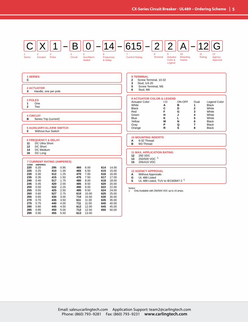
| 5 CX-Series Circuit Breaker - UL489 – Ordering Scheme
1Series
2Actuator
3Poles
5Aux/Alarm Switch
6Frequency& Delay
7Current Rating
8Terminal
9ActuatorColor &Legend
10MountingInserts
11Rating
12AgencyApproval
4 Circuit
C X B 2 A1 0 2 12 G14 615
1 SERIESC
2 ACTUATORX Handle, one per pole
8 TERMINAL2 Screw Terminal, 10-323 Stud, 1/4-205 Screw Terminal, M56 Stud, M6
3 POLES 1 One2 Two
4 CIRCUITB Series Trip (current)
5 AUXILIARY/ALARM SWITCH0 Without Aux Switch
6 FREQUENCY & DELAY11 DC Ultra Short12 DC Short14 DC Medium16 DC Long
7 CURRENT RATING (AMPERES)CODE AMPERES220 0.20225 0.25230 0.30235 0.35240 0.40245 0.45250 0.50255 0.55260 0.60265 0.65270 0.70275 0.75280 0.80285 0.85290 0.90
295 0.95410 1.00512 1.25415 1.50517 1.75420 2.00522 2.25425 2.50527 2.75430 3.00435 3.50440 4.00445 4.50450 5.00455 5.50
460 6.00465 6.50470 7.00475 7.50480 8.00485 8.50490 9.00495 9.50610 10.00710 10.50611 11.00711 11.50612 12.00712 12.50613 13.00
614 14.00615 15.00616 16.00617 17.00618 18.00620 20.00622 22.00624 24.00625 25.00630 30.00635 35.00640 40.00645 45.00650 50.00
11 MAX. APPLICATION RATING 12 250 VDC13 250/500 VDC 1
15 205/410 VDC
12 AGENCY APPROVALA Without ApprovalsG UL 489 ListedS UL 489 Listed, TUV to IEC60947-2 1
Notes: 1 Only Available with 250/500 VDC up to 15 amps.
10 MOUNTING INSERTSA 6-32 ThreadB M3 Thread
9 ACTUATOR COLOR & LEGENDActuator Color I-O ON-OFF Dual Legend ColorWhite A B 1 BlackBlack C D 2 WhiteRed F G 3 WhiteGreen H J 4 WhiteBlue K L 5 WhiteYellow M N 6 BlackGray P Q 7 BlackOrange R S 8 Black
Email: [email protected] Application Support: [email protected] Phone: (860) 793–9281 Fax: (860) 793–9231 www.carlingtech.com
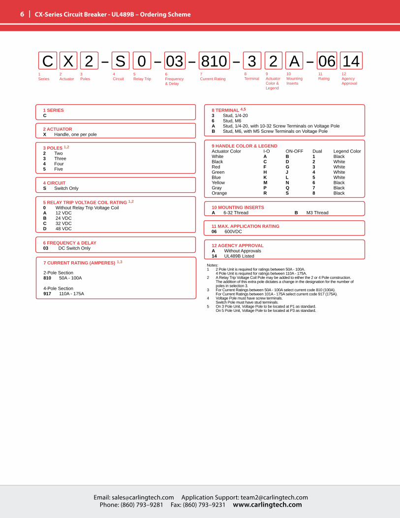
6 | CX-Series Circuit Breaker - UL489B – Ordering Scheme
1Series
2Actuator
3Poles
5Relay Trip
6Frequency& Delay
7Current Rating
8Terminal
12AgencyApproval
4 Circuit
C X S 3 A2 0 2 06 1403 810
1 SERIESC
2 ACTUATORX Handle, one per pole
10 MOUNTING INSERTSA 6-32 Thread B M3 Thread
3 POLES 1,2 2 Two 3 Three4 Four 5 Five
4 CIRCUITS Switch Only
5 RELAY TRIP VOLTAGE COIL RATING 1,2
0 Without Relay Trip Voltage CoilA 12 VDCB 24 VDCC 32 VDCD 48 VDC
6 FREQUENCY & DELAY03 DC Switch Only
7 CURRENT RATING (AMPERES) 1,3
2-Pole Section810 50A - 100A
4-Pole Section917 110A - 175A
9 HANDLE COLOR & LEGENDActuator Color I-O ON-OFF Dual Legend ColorWhite A B 1 BlackBlack C D 2 WhiteRed F G 3 WhiteGreen H J 4 WhiteBlue K L 5 WhiteYellow M N 6 BlackGray P Q 7 BlackOrange R S 8 Black
11 MAX. APPLICATION RATING 06 600VDC
12 AGENCY APPROVALA Without Approvals14 UL489B Listed
9ActuatorColor &Legend
10MountingInserts
11Rating
8 TERMINAL 4,5
3 Stud, 1/4-206 Stud, M6A Stud, 1/4-20, with 10-32 Screw Terminals on Voltage PoleB Stud, M6, with M5 Screw Terminals on Voltage Pole
Notes: 1 2 Pole Unit is required for ratings between 50A - 100A. 4 Pole Unit is required for ratings between 110A - 175A.2 A Relay Trip Voltage Coil Pole may be added to either the 2 or 4 Pole construction. The addition of this extra pole dictates a change in the designation for the number of poles in selection 3.3 For Current Ratings between 50A - 100A select current code 810 (100A). For Current Ratings between 101A - 175A select current code 917 (175A).4 Voltage Pole must have screw terminals. Switch Pole must have stud terminals.5 On 3 Pole Unit, Voltage Pole to be located at P1 as standard. On 5 Pole Unit, Voltage Pole to be located at P3 as standard.
Email: [email protected] Application Support: [email protected] Phone: (860) 793–9281 Fax: (860) 793–9231 www.carlingtech.com
Email: [email protected] Application Support: [email protected] Phone: (860) 793–9281 Fax: (860) 793–9231 www.carlingtech.com
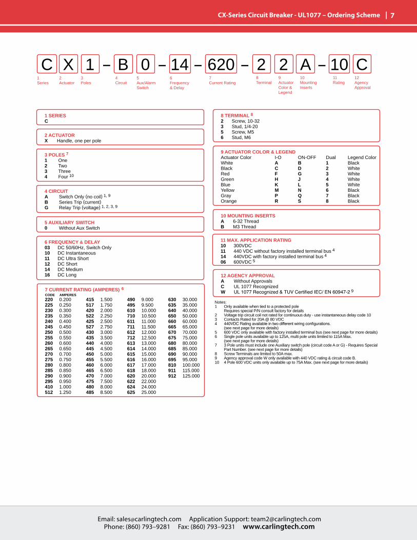
| 7 CX-Series Circuit Breaker - UL1077 – Ordering Scheme
10 MOUNTING INSERTSA 6-32 ThreadB M3 Thread
9 ACTUATOR COLOR & LEGENDActuator Color I-O ON-OFF Dual Legend ColorWhite A B 1 BlackBlack C D 2 WhiteRed F G 3 WhiteGreen H J 4 WhiteBlue K L 5 WhiteYellow M N 6 BlackGray P Q 7 BlackOrange R S 8 Black
1Series
2Actuator
3Poles
5Aux/Alarm Switch
6Frequency& Delay
7Current Rating
8Terminal
12AgencyApproval
4 Circuit
C X B 2 A1 0 2 10 C14 620
1 SERIESC
2 ACTUATORX Handle, one per pole
8 TERMINAL 82 Screw, 10-323 Stud, 1/4-205 Screw, M56 Stud, M6
3 POLES 7 1 One2 Two 3 Three4 Four 10
4 CIRCUITA Switch Only (no coil) 1, 9
B Series Trip (current)G Relay Trip (voltage) 1, 2, 3, 9
5 AUXILIARY SWITCH0 Without Aux Switch
6 FREQUENCY & DELAY03 DC 50/60Hz, Switch Only 10 DC Instantaneous11 DC Ultra Short12 DC Short14 DC Medium16 DC Long
7 CURRENT RATING (AMPERES) 6 CODE AMPERES
220 0.200225 0.250230 0.300235 0.350240 0.400245 0.450250 0.500255 0.550260 0.600265 0.650270 0.700275 0.750280 0.800285 0.850290 0.900295 0.950410 1.000512 1.250
415 1.500517 1.750420 2.000522 2.250425 2.500527 2.750430 3.000435 3.500440 4.000445 4.500450 5.000455 5.500460 6.000465 6.500470 7.000475 7.500480 8.000485 8.500
490 9.000495 9.500610 10.000710 10.500611 11.000711 11.500612 12.000712 12.500613 13.000614 14.000615 15.000616 16.000617 17.000618 18.000620 20.000622 22.000624 24.000625 25.000
630 30.000635 35.000640 40.000650 50.000660 60.000665 65.000670 70.000675 75.000680 80.000685 85.000690 90.000695 95.000810 100.000911 115.000912 125.000
11 MAX. APPLICATION RATING 10 300VDC 11 440 VDC without factory installed terminal bus 4
14 440VDC with factory installed terminal bus 4
06 600VDC 5
12 AGENCY APPROVALA Without ApprovalsC UL 1077 RecognizedW UL1077Recognized&TUVCertifiedIEC/EN60947-2 9
9ActuatorColor &Legend
10MountingInserts
11Rating
Notes: 1 Only available when tied to a protected pole Requires special P/N consult factory for details2 Voltage trip circuit coil not rated for continuous duty - use instantaneous delay code 103 Contacts Rated for 20A @ 80 VDC4 440VDCRatingavailableintwodifferentwiringconfigurations. (see next page for more details)5 600 VDC only available with factory installed terminal bus (see next page for more details)6 Single pole units available up to 125A, multi pole units limited to 115A Max. (see next page for more details)7 3 Pole units must include one Auxiliary switch pole (circuit code A or G) - Requires Special Part Number. (see next page for more details)8 Screw Terminals are limited to 50A max.9 Agency approval code W only available with 440 VDC rating & circuit code B.10 4 Pole 600 VDC units only available up to 75A Max. (see next page for more details)
Email: [email protected] Application Support: [email protected] Phone: (860) 793–9281 Fax: (860) 793–9231 www.carlingtech.com
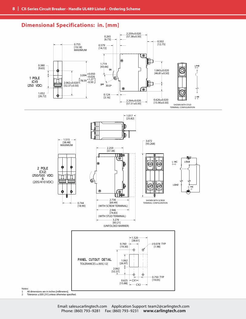
8 | CX-Series Circuit Breaker - Handle UL489 Listed – Ordering Scheme
SHOWN WITH STUDTERMINAL CONFIGURATION
0.755[19.18]MAXIMUM
0.380[9.65]
1.052[26.72]
3.094
78.59
+0.050–0.020+1.27–0.502.062+0.020
[52.37+0.50]
1.719[43.66]
0.124[3.16]
0.579[14.72]
0.265[6.73]
0.502[12.75]
2.259+0.020[57.38+0.50]
1.843+0.020[46.81+0.50]
0.626+0.020[15.90+0.50]
2.264+0.020[57.51+0.50]
30.0º
1.515[38.48]
MAXIMUM
3.672[93.268]
1.017[25.82]
0.744[18.90]
2.259[57.38]
SHOWN WITH SCREWTERMINAL CONFIGURATION
2.736[69.49]
(WITH SCREW TERMINAL)2.946[74.83]
(WITH STUD TERMINAL)3.276[83.21]
0.625[15.88]
(UNFOLDED BARRIER)
TOLERANCES +.005[.12]
CX1CX2
1.520[38.61]
0.760[19.30]
2.062[52.37]
1.062[26.97]
0.750 TYP[19.05]
0.078 TYP[1.98]
&(205/410 VDC)
Notes: 1 All dimensions are in inches [millimeters].2 Tolerance±.020[.51]unlessotherwisespecified.
Dimensional Specifications: in. [mm]
Email: [email protected] Application Support: [email protected] Phone: (860) 793–9281 Fax: (860) 793–9231 www.carlingtech.com
Email: [email protected] Application Support: [email protected] Phone: (860) 793–9281 Fax: (860) 793–9231 www.carlingtech.com
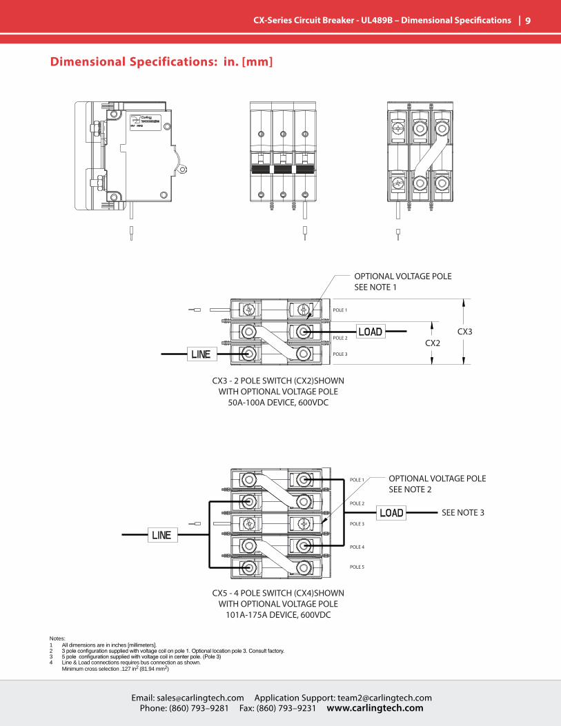
| 9 CX-Series Circuit Breaker - UL489B – Dimensional Specifications
POLE 5
POLE 4
POLE 3
POLE 2
POLE 1
POLE 3
POLE 2
POLE 1
CX2CX3
OPTIONAL VOLTAGE POLESEE NOTE 1
CX3 - 2 POLE SWITCH (CX2)SHOWNWITH OPTIONAL VOLTAGE POLE
50A-100A DEVICE, 600VDC
CX5 - 4 POLE SWITCH (CX4)SHOWNWITH OPTIONAL VOLTAGE POLE
101A-175A DEVICE, 600VDC
OPTIONAL VOLTAGE POLESEE NOTE 2
SEE NOTE 3
Notes: 1 All dimensions are in inches [millimeters].2 3poleconfigurationsuppliedwithvoltagecoilonpole1.Optionallocationpole3.Consultfactory.3 5poleconfigurationsuppliedwithvoltagecoilincenterpole.(Pole3)4 Line & Load connections requires bus connection as shown. Minimum cross selection .127 in2 (81.94 mm2)
Dimensional Specifications: in. [mm]
Email: [email protected] Application Support: [email protected] Phone: (860) 793–9281 Fax: (860) 793–9231 www.carlingtech.com
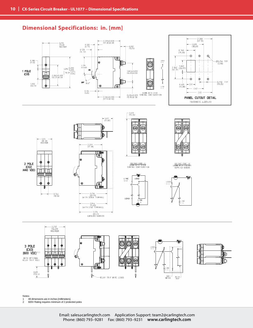
10 | CX-Series Circuit Breaker - UL1077 – Dimensional Specifications
Dimensional Specifications: in. [mm]
Notes: 1 All dimensions are in inches [millimeters].2 600V Rating requires minimum of 2 protected poles
Email: [email protected] Application Support: [email protected] Phone: (860) 793–9281 Fax: (860) 793–9231 www.carlingtech.com
Email: [email protected] Application Support: [email protected] Phone: (860) 793–9281 Fax: (860) 793–9231 www.carlingtech.com
| 11 Reps & Contact
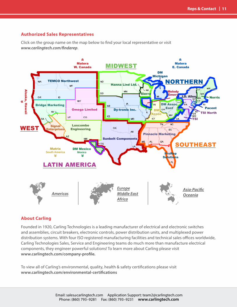
TEMCO NorthwestHanna Lind Ltd.
SierraLD. Allen Norris
PacentTSI North
TSI
DM AssocEastDy-tronix Inc.
Sunbelt ComponentsPinnacle Marketing
Omega LimitedBridge Marketing
Alaska, H
awaii
MateraW. Canada
LuscombeEngineering
SignalEnterprises
MateraE. Canada
DMMichigan
DM MexicoMexico
MatrixSouth America
DMAssoc
MelodyEmery
ProRepSolutions
Authorized Sales Representatives
About Carling
Founded in 1920, Carling Technologies is a leading manufacturer of electrical and electronic switches and assemblies, circuit breakers, electronic controls, power distribution units, and multiplexed power distribution systems. With four ISO registered manufacturing facilities and technical sales offices worldwide, Carling Technologies Sales, Service and Engineering teams do much more than manufacture electrical components, they engineer powerful solutions! To learn more about Carling please visit www.carlingtech.com/company-profile.
To view all of Carling’s environmental, quality, health & safety certifications please visit www.carlingtech.com/environmental-certifications
Click on the group name on the map below to find your local representative or visit www.carlingtech.com/findarep.
AmericasEuropeMiddle EastAfrica
Asia-PacificOceania
«
«
«««
MIDWEST
NORTHERN
SOUTHEAST
LATIN AMERICA
WEST
Worldwide HeadquartersCarling Technologies, Inc.60 Johnson Avenue, Plainville, CT 06062Phone: 860.793.9281 Fax: 860.793.9231Email: [email protected]
Northern Region Sales Office: [email protected] Region Sales Office: [email protected] Region Sales Office: [email protected] Region Sales Office: [email protected] America Sales Office: [email protected]
Asia-Pacific HeadquartersCarling Technologies, Asia-Pacific Ltd.,Kowloon, Hong KongPhone: Int + 852-2737-2277 Fax: Int + 852-2736-9332Email: [email protected]
Shenzhen, China: [email protected], China: [email protected], India: [email protected], Taiwan: [email protected], Japan: [email protected]
Europe | Middle East | Africa HeadquartersCarling Technologies LTD4 Airport Business Park, Exeter Airport, Clyst Honiton, Exeter, Devon, EX5 2UL, UKPhone: Int + 44 1392.364422 Fax: Int + 44 1392.364477Email: [email protected]
Germany: [email protected]: [email protected]
www.carlingtech.com REV_06_2016