Embed Size (px)
Citation preview
Proceedings of the Annual Stability Conference
Structural Stability Research Council Baltimore, Maryland, April 10-13, 2018
Cyclic Fracture Simulation Framework for Stability and Collapse Simulation in Steel Structures
David A. Padilla-Llano1, Jerome F. Hajjar2, Matthew R. Eatherton3, W. Samuel Easterling4, Benjamin W. Schafer5
Abstract This paper presents a finite element based framework for direct simulation of cyclic fracture in steel components and connections with application to predict failure and collapse of steel structures. Collapse and failure of steel structures subjected to extreme loads, such as seismic loads, often is preceded by large inelastic deformations that could lead to fracture in components and connections. However, direct simulation of damage and fracture in the performance assessment of steel structures is challenging and it has not been a common practice in prior work. The framework presented combines a plasticity model for large deformations that captures plastic work stagnation and the Bauschinger effect, with a damage model to simulate fracture initiation, propagation and failure through an element deletion strategy. The damage model includes the effects of non-proportional loading and plastic strain history in the fracture initiation and propagation process. Calibration of the model parameters is discussed for common grades of structural steel, weldments and bolts using typical material tests. The framework capabilities are validated against experiments including ancillary material tests, steel components, and subassemblies of steel structures that experienced fracture subjected to monotonic and cyclic loading. This proposed framework provides a robust and valuable tool for stability analysis and simulations of collapse triggered by fracture in components and connections of three-dimensional steel structures subjected to extreme loads.
1 Post-doctoral Research Associate, Department of Civil and Environmental Engineering, Northeastern University, <[email protected]>
2 CDM Smith Professor and Department Chair, Department of Civil and Environmental Engineering, Northeastern University, <[email protected]>
3 Associate Professor, Department of Civil and Environmental Engineering, Virginia Polytechnic Institute and State University, <[email protected]>
4 Montague-Betts Professor and Department Head, Department of Civil and Environmental Engineering, Virginia Polytechnic Institute and State University, <[email protected]>
5 Professor and Swirnow Family Faculty Scholar, Department of Civil Engineering, Johns Hopkins University, <[email protected]>
2
1. Introduction Failure and collapse of steel structures subjected to extreme loads, e.g., seismic loads, often is preceded by large inelastic deformations that could lead to fracture in components and connections. The importance of understanding the damage progression preceding fracture in components and connections is highlighted by failure cases such as the Alexander Kielland drilling rig collapse in 1980 (Almar-Naess et al. 1984), the structural failures triggered by fracture in steel components and connections observed after the 1994 Northridge and 1995 Kobe earthquakes (Chung et al. 1996, Cooper et al. 1994, Mahin 1998), among many other cases. Moreover, these failure cases highlight the importance of accounting properly for fracture in the analysis and design of steel structures subjected to extreme loads. However, simulating fracture in steel structures is challenging because it requires analysis tools not readily available to most practicing engineers. Accurately simulating steel structural systems where damage localization and fracture may occur at several locations requires a strategy that generally involves fine-grained computational finite element meshes. This presents limitations on the fracture models type used where computational time and accuracy of the simulated fracture process are competing factors that limit the options to widely include fracture analyses. In recent years, a variety of approaches to simulate fracture in steel structures have been proposed, including traditional linear elastic (LEFM) and elastic-plastic fracture mechanics (EPFM) formulations that rely on stress intensities factors and (Rice 1968, Rice and Rosengren 1968, Hutchinson 1968, Rooke and Cartwright 1976, Kumar et al. 1984), void growth-coalescence based models (e.g., Kanvinde et al. 2007, Xue et al. 2008, Bai et al. 2008, Cao et al. 2014, Wen et al. 2016a-b,), and extended finite elements models (XFEM) that uses enriched elements to model propagation of discontinuities, e.g. fractures (Moës 1999, Fries and Belytschko 2010). Kanvinde (2016) summarizes some of such approaches popular in the context of civil engineering steel structures and discusses their advantages and drawbacks. This paper introduces a cyclic fracture framework developed for metals to simulate damage leading to fracture in steel components, connections and subassemblies. The framework implements a continuum damage-plasticity model for large deformations that accounts for the effects of stress triaxiality, Lode angle, non-proportional loading, strain history effects, and fracture energy dissipation. An element deletion strategy is adopted to simulate fracture propagation. The proposed framework enables to simulate localized damage and fracture in components and connections that could trigger collapse in steel structures using mesh densities that are typical of high-fidelity structural analyses. 2. New Cyclic Fracture Model for Metals The process leading to load-carrying capacity loss due to fracture in the context of finite elements was implemented using a hybrid approach that combines a damage-plasticity model for large plastic strains and an element deletion strategy. The plasticity model by Yoshida and Uemori (2002) is coupled to a damage model derived from the models proposed by Wen and Mahmoud (2016b) and Hillerborg (1976) to simulate the material plastic stress-strain response including softening of the response due to fracture. 2.1 Coupled Damaged-Plasticity Model for Large Plastic Strains The Yoshida-Uemori (YU) model is capable of simulating the cyclic behavior in metals experiencing large plastic strains, isotropic and kinematic hardening, the Bauschinger effect, and plastic work stagnation. Furthermore, the YU model ensures stabilization of the plastic hardening for cyclic loading with constant strain amplitudes (Yoshida and Uemori 2002; Jia et al. 2014), a
3
shortcoming present in popular models with combined kinematic-isotropic hardening, e.g., the model by Lemaitre and Chaboche (1990). The YU model employs three coupled surfaces to describe the large-strain cyclic behavior of metals. A constant-size yield surface with constant size
is coupled to a bounding surface of varying size to control the isotropic and kinematic hardening. The overall hardening is represented by the isotropic hardening of the bounding surface while the kinematic hardening of the yield surface describes the Bauschinger effect seen during loading reversals. A strain-based memory surface of size is used to simulate the plastic-work hardening stagnation and yield plateau. The three surfaces are described by: ( , ) = ( − ): ( − ) / − (1 − ) = 0 [yield] (1a)( , ) = ( − ): ( − ) / − (1 − ) = 0 [bounding] (1b), = ( − ): ( − ) / − = 0 [memory] (1c)
where = deviatoric stress tensor, = yield surface center, = bounding surface center, = damage variable to control the strain-stress response softening due to fracture, = plastic strain tensor, and = memory surface center. The kinematic hardening of the yield and bounding surfaces is coupled through the backstress = − that describes the relative kinematic motion between both surfaces. The evolution rules of and are defined by: = ( ) − ( / ̅) / ̅ (2a)= ( ) − ̅ (2b)
where ̅ = equivalent plastic strain; = − ; ̅ = [(3 2⁄ ) : ] / ; and , and are model parameters. The size of the bounding surface is a function of the equivalent plastic strain and has an initial size > . The evolution rule for follows a modified version of the rule proposed by Zaverl and Lee (1978) that defines the increment in terms of the saturation stress and a hardening linear term introduced by Jia et al. (2014). The term accounts for experimentally observed trends where the true stress does not saturate but continues increasing approximately linearly at large plastic strains. The expression for is = ( + ) ̅ (3) The memory surface proposed by Ohno (1982) is adopted to memorize the hardening history, and it determines the non-isotropic hardening portion of the bounding surface. Non-isotropic hardening of the bounding surface occurs when the current plastic strain is inside the memory surface. Thus,
= 0 when ( − ): ≤ 0 and ( , ) < 0. The evolution of and are given by = − : ̅ (4a)= ( ) − : ̅ (4b) where ℎ is a material parameter. The yield plateau is simulated by assuming an initial memory surface size = ̅ and setting and equal to 0.001 and 0.001 respectively for ̅ ≤ ̅ .
4
2.2 Damage Leading to Fracture Model Damage is implemented in two stages: the first one corresponds to damage accumulated that triggers fracture initiation, and a second stage where damage accumulation results in weakening of the material stress-strain response associated to the evolution of fracture. Here damage is defined as the material’s loss of deformation capability, and it is considered a self-similar process on any deviatoric proportional path for any hydrostatic pressure (Xue 2007). Thus, damage is expressed as a function of the plastic strain to fracture strain ratio, and the hydrostatic pressure and deviatoric stresses effects are assumed independent of each other. The nonlinear history and strain based damage evolution proposed by Wen and Mahmoud (2016b) is used as a template to implement the damage leading to fracture initiation, and an enhanced version of the Hillerborg’s (1976) approach is proposed for the damage that results in softening of the material response due to crack opening. Each part of the proposed model are described next. 2.2.1 Damage to fracture initiation The damage accumulated that triggers fracture initiation is defined as a function of the equivalent plastic strain and the current stress state. A state variable is introduced to quantify the damage accumulated up to the fracture initiation point, where = 0 for no-damage, and = 1 for fracture initiation. is not coupled to the plasticity model and its purpose is to trigger the softening of the material stress-strain response. The incremental form for is = ∙ ̅ ̅ ̅ (5)
where 1, 2 = material constants, ̅ = [(2/3) : ] / is the transient equivalent plastic strain, ̅ is the fracture initiation strain surface, and = the parameter that accounts for the non-proportional and loading history effects in the damage accumulation process. The commonly used linear damage accumulation model is recovered when 1 = 0 and 2 = 1 in Eq. 5 (Bai and Wierzbicki 2008, Bai 2008). 2.2.2 Fracture propagation model The damage process that drives the material strain-stress response softening is based on the assumption that the material losses load-carrying capacity as fracture plastic work accumulates after fracture initiation. Failure of the material is assumed when the fracture plastic work exceeds the material’s fracture energy capacity . The fracture energy expression is defined in terms of the characteristic length to reduce mesh dependency as proposed by Hillerborg (1976). Damage after fracture initiation is assumed to increase exponentially with the fracture plastic work, and includes the non-proportional and history loading effects as follows = ℋ( − 1) ∙ 1 − ∙ ∙ /
(6)
where ℋ(·) = Heaviside function, = parameter set to 1, and is a fracture energy surface described in the next section. The damage variable is coupled to the YU plasticity model to simulate the material load-carrying capacity loss. When the load-carrying capacity is exhausted at an integration point ( = 1), this is deleted, and once all integration points associated to an element are deleted, the element is removed.
5
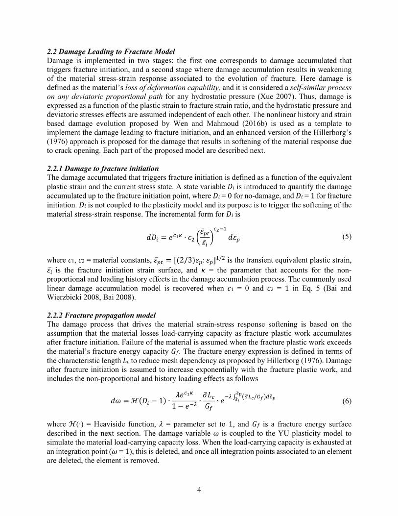
2.2.3 Fracture initiation strain surface The fracture initiation strain surface ̅ is given by the expression ̅ = ̅ ∙ ∙ (1 + | | ) (7) where the exponential term represents the stress triaxiality = /3 effect, and the term in parenthesis is the influence of the Lode angle parameter = 1 − (2/π) cos [(27/2) / ], with = (3 ) / being the von Mises stress, and 1, 2 and 3 are stress tensor invariants. In Eq. 7 ̅ is the fracture initiation strain for the generalized shear or torsion loading case (i.e., = = 0), is the ratio of fracture strain of the generalized shear loading case ( = 0) to the generalized tension/compression loading case ( = ±1), and 3 and 4 are material parameters that control the surface’s curvature. Fig. 1 illustrates the influence of each parameter in Eq. 7. Different coefficients can be chosen to represent the behavior of different materials. For example, a material more ductile in tension ( = 1) than in shear ( = 0), and 4 can be set to provide a surface to reflect such nature, e.g., blue curve in Fig. 1c. Now, if a material is more ductile in pure shear than in tension, a value of ≤ 0, e.g., the green curve in Fig. 1b, or any curve with 4 ≥ 0 in Fig. 1c could be adopted. ̅ is also symmetric about the axis defined by = 0. The surface ̅ represents the fracture initiation strain for the proportional monotonic loading condition, where fracture initiation, determined by Eq. 5, starts when the equivalent plastic strain equates the value given by Eq. 7. For non-proportional loading cases such as cyclic loading, Eq. 7 acts as a weighing function in the incremental damage to fracture initiation function to include the effects of changing triaxiality and Lode angle parameter. The fracture initiation surface proposed here is chosen for its simplicity and because it can represent a large family of surfaces as suggested in Fig. 1, including surfaces previously proposed by other authors (e.g., Bai and Wierzbicki 2008 and 2009, Wen and Mahmoud 2016a, Xue 2007, Xue and Wierzbicki 2008, Cao et al. 2014).
Figure 1: Effects of parameters 3 (a), 4 (b) and (c) in the fracture initiation strain surface.
2.2.4 Fracture energy surface The fracture energy surface proposed here is based on the assumption that the energy dissipated after fracture initiation is directly related to the stress triaxiality and Lode angle parameter at the tip of fracture. The function adopted to express this relationship is the same as that of the fracture initiation surface, thus
6
= ∙ ∙ (1 + | | ) (8) with = the fracture energy for generalized shear or torsion. Adopting this definition of accounts for the differences in the fracture process when loading in pure tension, pure shear or any other mixed stress state. 2.2.4 Non-proportional and history loading parameter The non-proportionality loading effects are partially accounted for by the including the triaxiality and Lode angle parameter dependencies in the fracture initiation strain (Bai 2008) and fracture energy surfaces. However, for complex load histories (e.g., reverse cyclic loading) an additional parameter is required to describe the effects on damage accumulation of the previous non-proportional and cyclic loading history. This parameter accelerates or deaccelerates the damage accumulation rate for the cases of cyclic and non-proportional loading. The expression for is given by = ̅ (9)
with = sign Σ Σ 1 − :‖ ‖‖ ‖ (10)
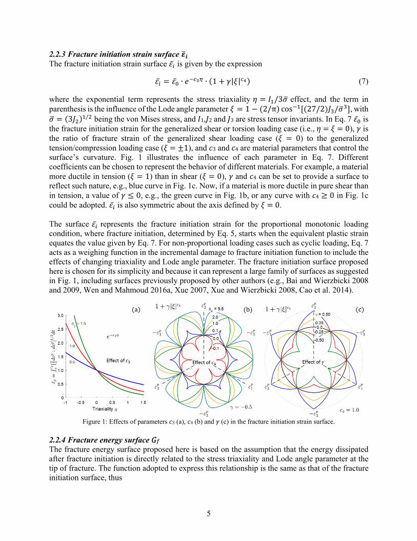
where ∈ [−2,2] describes the non-proportionality state and changes in loading direction. Both and are zero for monotonic proportional loading cases and non-zero otherwise. Similar parameters have been proposed by Bai (2008), Wen et al. (2016b) and Algarni et al. (2017). An example of the evolution of parameters and is illustrated in Fig. 2 for a cyclic tension-compression with constant amplitude case. In this example reaches a value of −2 corresponding to a change in loading direction from tension to compression and as cyclic loading continues, fluctuates between −2 and 2. Parameter starts from zero, then decreases to negative values in the first reversal and fluctuates between negative and positive values. Fig. 2 also shows an example for a case dominated by cyclic shear stresses, where behaves less like a pulse and varies throughout each half cycle.
Figure 2: Example of the history parameters evolution (a) and (b).
7
2.2.5 Non-damage accumulation (cut-off) region A cutoff region is defined based on the assumption that damage only accumulates for stress states with maximum positive principle stresses, i.e., 1 ≥ 0 (Cockcroft et al. 1968, Brozzo et al. 1972, Oh. et al. 1979, Wen et al. 2016b). Thus, no damage is accumulated when 1 ≤ 0, or in terms of stress triaxiality and Lode angle parameter, = 0 if ≤ −2/3cos[ /6( − 1)] (11) 2.3 Integration of the Constitutive Equations The cyclic fracture model is implemented as a user material using an implicit staggered stress integration algorithm. The backward Euler discretization and the successive substitution method are used to find the current stress +1 as a function of the increments in total strain +1 and the damage increment +1 as follows = [1 − ]ℂ : = ℂ : [ − ]
= ℂ : [ + ] − ℂ : + ℂ : (12)
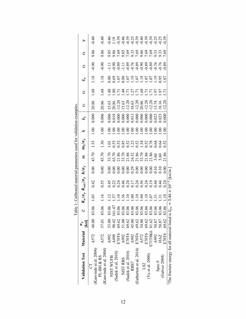
where = 1 − , ℂ = undamaged elastic isotropic stiffness tensor, and = elastic part of the total strain tensor. In the staggered integration algorithm, first, a trial elastic stress (first term in Eq. 12) is calculated based on the material status at the -step, then the plastic correction (second term in Eq. 12) is performed in the absence of damage evolution ( +1 = 0) to find , finally the damage correction step (third term in Eq. 12) is performed under frozen plasticity conditions. An adaptive sub-stepping algorithm was also implemented to improve convergence for large strain increments. The resulting algorithm is robust with CPU times faster to that of a classical two steps elastic-predictor/plastic-damage corrector schemes (Cao 2014, Soyarslan et al. 2010). 3. Model Calibration Procedure Calibration of the proposed model parameters for a particular material is achieved in two steps: (1) calibration of the modified YU plasticity model, and (2) calibration of the fracture initiation and propagation models. In both steps, parameters are determined using a global optimization algorithm that minimizes the weighted error between experimental and simulated load-deformation responses. Monotonic tension and cyclic tension-compression tests of classic steel coupons, circular notched bars, or grooved plates are specimens recommended to calibrate the YU model, see Fig. 3a. To calibrate the fracture initiation and propagation models test data from specimens that exhibit different triaxiality and Lode angle parameters ranges up to fracture is key. Fig. 3a illustrates typical specimens used to characterize fracture and where the projection of their fracture initiation strain onto the – plane for the monotonic loading case falls. A set of these specimens can provide enough information to calibrate the proposed model. Note that cyclic tests are necessary to calibrate the coefficients associated to the non-proportional and loading history parameter. Parameters for structural steels A572 and A992 both Grade 50; weldments E70T6 and E71T8-K6; and A490 bolts were calibrated using monotonic and cyclic tests reported by Smith et al. (2014), Kanvinde et al. (2004), Myers et al. (2013), Deng et al. (2003), Ng et al. (2002), and Kulak et al. (1986). An example of the fracture initiation strain surface calibrated for A572 grade 50 structural
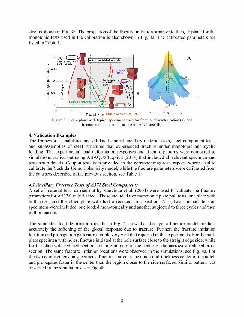
8
steel is shown in Fig. 3b. The projection of the fracture initiation strain onto the – plane for the monotonic tests used in the calibration is also shown in Fig. 3a. The calibrated parameters are listed in Table 1.
Figure 3: vs. plane with typical specimens used for fracture characterization (a), and
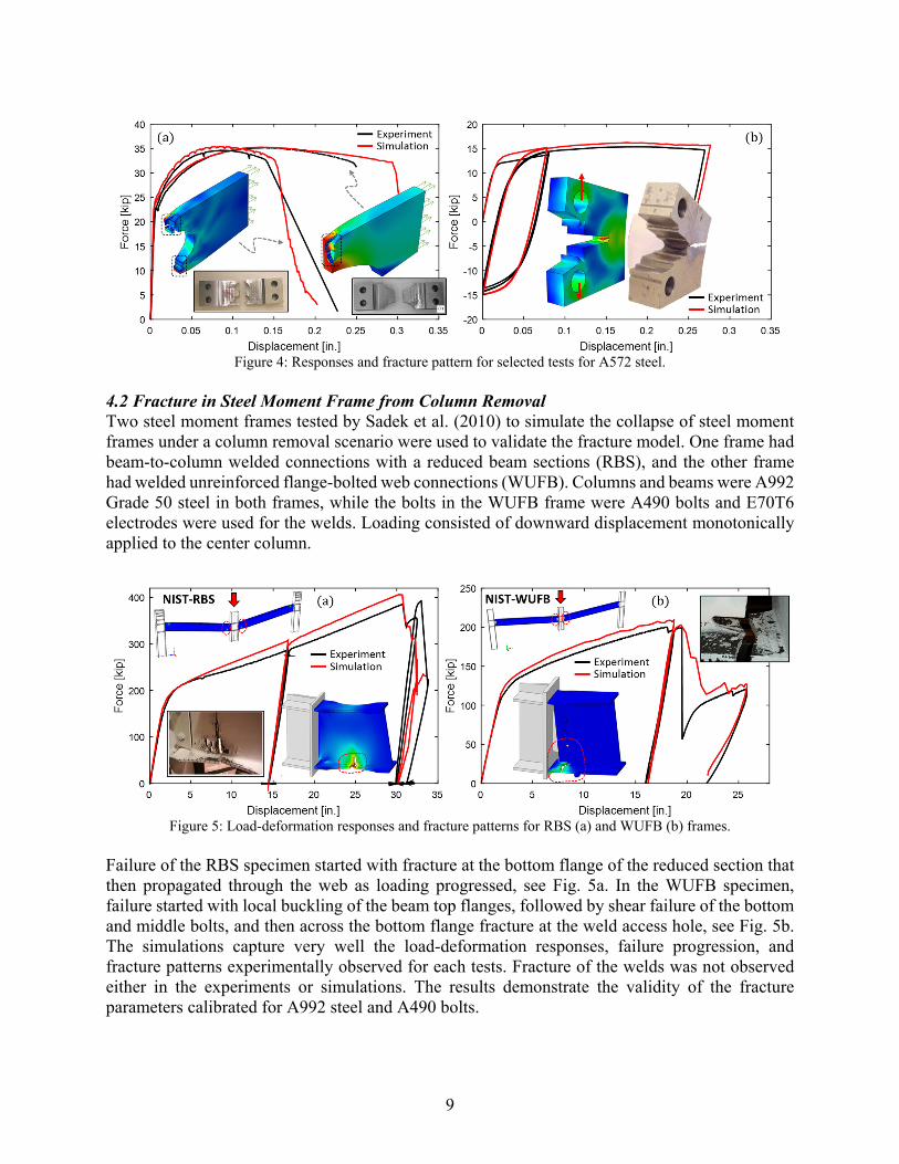
fracture initiation strain surface for A572 steel (b). 4. Validation Examples The framework capabilities are validated against ancillary material tests, steel component tests, and subassemblies of steel structures that experienced fracture under monotonic and cyclic loading. The experimental load-deformation responses and fracture patterns were compared to simulations carried out using ABAQUS/Explicit (2014) that included all relevant specimen and tests setup details. Coupon tests data provided in the corresponding tests reports where used to calibrate the Yoshida-Uemori plasticity model, while the fracture parameters were calibrated from the data sets described in the previous section, see Table 1. 4.1 Ancillary Fracture Tests of A572 Steel Components A set of material tests carried out by Kanvinde et al. (2004) were used to validate the fracture parameters for A572 Grade 50 steel. These included two monotonic plate pull tests, one plate with bolt holes, and the other plate with had a reduced cross-section. Also, two compact tension specimens were included, one loaded monotonically and another subjected to three cycles and then pull in tension. The simulated load-deformation results in Fig. 4 show that the cyclic fracture model predicts accurately the softening of the global response due to fracture. Further, the fracture initiation location and propagation patterns resemble very well that reported in the experiments. For the pull-plate specimen with holes, fracture initiated at the hole surface close to the straight edge side, while for the plate with reduced section, fracture initiates at the center of the narrowest reduced cross section. The same fracture initiation locations were observed in the simulations, see Fig. 4a. For the two compact tension specimens, fracture started at the notch mid-thickness center of the notch and propagates faster in the center than the region closer to the side surfaces. Similar pattern was observed in the simulations, see Fig. 4b.
9
Figure 4: Responses and fracture pattern for selected tests for A572 steel.
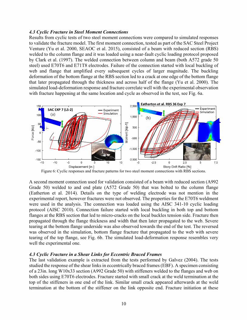
4.2 Fracture in Steel Moment Frame from Column Removal Two steel moment frames tested by Sadek et al. (2010) to simulate the collapse of steel moment frames under a column removal scenario were used to validate the fracture model. One frame had beam-to-column welded connections with a reduced beam sections (RBS), and the other frame had welded unreinforced flange-bolted web connections (WUFB). Columns and beams were A992 Grade 50 steel in both frames, while the bolts in the WUFB frame were A490 bolts and E70T6 electrodes were used for the welds. Loading consisted of downward displacement monotonically applied to the center column.
Figure 5: Load-deformation responses and fracture patterns for RBS (a) and WUFB (b) frames.
Failure of the RBS specimen started with fracture at the bottom flange of the reduced section that then propagated through the web as loading progressed, see Fig. 5a. In the WUFB specimen, failure started with local buckling of the beam top flanges, followed by shear failure of the bottom and middle bolts, and then across the bottom flange fracture at the weld access hole, see Fig. 5b. The simulations capture very well the load-deformation responses, failure progression, and fracture patterns experimentally observed for each tests. Fracture of the welds was not observed either in the experiments or simulations. The results demonstrate the validity of the fracture parameters calibrated for A992 steel and A490 bolts.
10
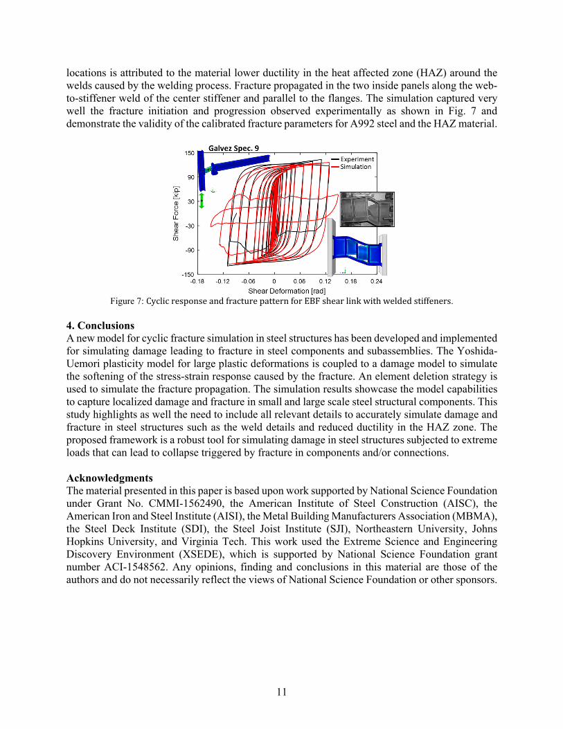
4.3 Cyclic Fracture in Steel Moment Connections Results from cyclic tests of two steel moment connections were compared to simulated responses to validate the fracture model. The first moment connection, tested as part of the SAC Steel Project Venture (Yu et al. 2000, SEAOC et al. 2015), consisted of a beam with reduced section (RBS) welded to the column flange and it was loaded using a near-fault cyclic loading protocol proposed by Clark et al. (1997). The welded connection between column and beam (both A572 grade 50 steel) used E70T6 and E71T8 electrodes. Failure of the connection started with local buckling of web and flange that amplified every subsequent cycles of larger magnitude. The buckling deformation of the bottom flange at the RBS section led to a crack at one edge of the bottom flange that later propagated through the thickness and across half of the flange (Yu et al. 2000). The simulated load-deformation response and fracture correlate well with the experimental observation with fracture happening at the same location and cycle as observed in the test, see Fig. 6a.
Figure 6: Cyclic responses and fracture patterns for two steel moment connections with RBS sections.
A second moment connection used for validation consisted of a beam with reduced section (A992 Grade 50) welded to and end plate (A572 Grade 50) that was bolted to the column flange (Eatherton et al. 2014). Details on the type of welding electrode was not mention in the experimental report, however fractures were not observed. The properties for the E70T6 weldment were used in the analysis. The connection was loaded using the AISC 341-10 cyclic loading protocol (AISC 2010). Connection failure started with local buckling in both top and bottom flanges at the RBS section that led to micro-cracks on the local buckles tension side. Fracture then propagated through the flange thickness and width that then later propagated to the web. Severe tearing at the bottom flange underside was also observed towards the end of the test. The reversed was observed in the simulation, bottom flange fracture that propagated to the web with severe tearing of the top flange, see Fig. 6b. The simulated load-deformation response resembles very well the experimental one. 4.3 Cyclic Fracture in a Shear Links for Eccentric Braced Frames The last validation example is extracted from the tests performed by Galvez (2004). The tests studied the response of the shear links in eccentrically braced frames (EBF). A specimen consisting of a 23in. long W10x33 section (A992 Grade 50) with stiffeners welded to the flanges and web on both sides using E70T6 electrodes. Fracture started with small crack at the weld termination at the top of the stiffeners in one end of the link. Similar small crack appeared afterwards at the weld termination at the bottom of the stiffener on the link opposite end. Fracture initiation at these
11
locations is attributed to the material lower ductility in the heat affected zone (HAZ) around the welds caused by the welding process. Fracture propagated in the two inside panels along the web-to-stiffener weld of the center stiffener and parallel to the flanges. The simulation captured very well the fracture initiation and progression observed experimentally as shown in Fig. 7 and demonstrate the validity of the calibrated fracture parameters for A992 steel and the HAZ material.
Figure 7: CyclicresponseandfracturepatternforEBFshearlinkwithweldedstiffeners.
4. Conclusions A new model for cyclic fracture simulation in steel structures has been developed and implemented for simulating damage leading to fracture in steel components and subassemblies. The Yoshida-Uemori plasticity model for large plastic deformations is coupled to a damage model to simulate the softening of the stress-strain response caused by the fracture. An element deletion strategy is used to simulate the fracture propagation. The simulation results showcase the model capabilities to capture localized damage and fracture in small and large scale steel structural components. This study highlights as well the need to include all relevant details to accurately simulate damage and fracture in steel structures such as the weld details and reduced ductility in the HAZ zone. The proposed framework is a robust tool for simulating damage in steel structures subjected to extreme loads that can lead to collapse triggered by fracture in components and/or connections. Acknowledgments The material presented in this paper is based upon work supported by National Science Foundation under Grant No. CMMI-1562490, the American Institute of Steel Construction (AISC), the American Iron and Steel Institute (AISI), the Metal Building Manufacturers Association (MBMA), the Steel Deck Institute (SDI), the Steel Joist Institute (SJI), Northeastern University, Johns Hopkins University, and Virginia Tech. This work used the Extreme Science and Engineering Discovery Environment (XSEDE), which is supported by National Science Foundation grant number ACI-1548562. Any opinions, finding and conclusions in this material are those of the authors and do not necessarily reflect the views of National Science Foundation or other sponsors.
12
T
able
1: C
alib
rate
d m
ater
ial p
aram
eter
s us
ed f
or v
alid
atio
n ex
ampl
es.
Val
idat
ion
Tes
t M
ater
ial
[k
si]
/
/ /
/
ℎ
1 2
3
4
CT
(K
anvi
nde
et a
l. 20
04)
A57
2 48
.00
83.0
6 1.
03
0.42
0.
00
43.7
0 1.
53
1.00
0.
000
20.8
6 1.
68
1.18
-0
.90
9.86
-0
.40
PL
-BH
& R
S
(Kan
vind
e et
al.
2004
) A
572
57.0
1 83
.06
1.16
0.
55
0.00
43
.70
1.30
1.
00
0.00
6 20
.86
1.68
1.
18
-0.9
0 9.
86
-0.4
0
NIS
T W
UF
B
(Sad
ek e
t al.
2010
)
A99
2 53
.00
83.0
6 1.
12
0.45
0.
00
33.7
0 1.
01
1.00
0.
006
15.6
3 1.
48
0.80
-1
.11
9.85
-0
.46
A49
0 98
.42
161.
47
1.57
0.
22
0.00
63
.70
0.55
1.
00
0.01
8 20
.86
1.80
0.
69
-0.9
0 9.
86
1.19
E
70T
6 69
.62
83.0
6 1.
10
0.24
0.
00
21.8
6 0.
52
1.00
0.
000
-12.
20
1.71
1.
07
-0.8
9 7.
69
-0.3
9 N
IST
RB
S
(Sad
ek e
t al.
2010
) A
992
51.0
0 83
.06
1.36
0.
46
0.00
33
.70
0.85
1.
00
0.00
6 15
.63
1.48
0.
80
-1.1
1 9.
85
-0.4
6 E
70T
6 69
.62
83.0
6 1.
10
0.24
0.
00
21.8
6 0.
52
1.00
0.
000
-12.
20
1.71
1.
07
-0.8
9 7.
69
-0.3
9 R
BS
7
(Eat
hert
on e
t al.
2014
) A
992
45.0
0 83
.06
1.00
0.
17
0.29
24
.52
1.23
1.
00
0.01
3 18
.63
1.27
1.
19
-0.7
6 9.
33
-0.2
5 E
70T
6 69
.62
83.0
6 1.
10
0.24
0.
00
21.8
6 0.
52
1.00
0.
000
-12.
20
1.71
1.
07
-0.8
9 7.
69
-0.3
9
LS
2
(Yu
et a
l. 20
00)
A57
2 54
.00
83.0
6 1.
04
0.56
0.
00
33.7
0 1.
54
1.00
0.
006
20.8
6 1.
68
1.18
-0
.90
9.86
-0
.40
E70
T6
69.6
2 83
.06
1.10
0.
24
0.00
21
.86
0.52
1.
00
0.00
0 -1
2.20
1.
71
1.07
-0
.89
7.69
-0
.39
E71
T8K
6 81
.62
83.0
6 1.
07
0.19
0.
00
21.8
6 0.
78
1.00
0.
000
-12.
20
1.71
1.
07
-0.8
9 7.
69
-0.3
9
Spe
c.9
(G
alve
z 20
04)
A99
2 50
.87
83.0
6 1.
31
0.44
0.
10
5.60
0.
64
1.00
0.
023
13.7
4 1.
97
1.19
-0
.76
9.33
-0
.25
HA
Z
50.8
7 83
.06
1.31
0.
44
0.10
5.
60
0.64
1.
00
0.02
3 18
.16
1.97
0.
95
-0.7
6 9.
33
-0.2
5 E
70T
6 69
.62
83.0
6 1.
10
0.24
0.
00
21.8
6 0.
52
1.00
0.
000
-12.
20
1.71
1.
07
-0.8
9 7.
69
-0.3
9 1 T
he f
ract
ure
ener
gy f
or a
ll m
ater
ial l
iste
d is
=5.46
×10 [
ksi/
in.]
13
References ABAQUS 6.14, (2014). Abaqus User Manual, Simulia, Dassault Systèmes, Providence, RI. AISC. ANSI/AISC 341-10, (2010). Seismic provisions for structural steel buildings. Chicago, IL, AISC. Algarni, M., Choi, Y., and Bai, Y. (2017). “A unified material model for multiaxial ductile fracture and extremely low
cycle fatigue of Inconel 718.” International Journal of Fatigue, 96, 162–177. Almar-Naess, A., Haagensen, P. J., Lian, B., Moan, T., and Simonsen, T. (1984). “Investigation of the Alexander L.
Kielland Failure-Metallurgical and Fracture Analysis.” Journal of Energy Resources Technology, 106(1), 24–31. Bai, Y. (2008). “Effect of loading history in necking and fracture”, Ph.D. dissertation, Massachusetts Institute of
Technology, Cambridge, MA. Bai, Y., and Wierzbicki, T. (2008). “A new model of metal plasticity and fracture with pressure and Lode dependence.”
International Journal of Plasticity, 24(6), 1071–1096. Bai, Y., and Wierzbicki, T. (2009). “Application of extended Mohr–Coulomb criterion to ductile fracture.”
International Journal of Fracture, 161(1), 1–20. Brozzo, P., Deluca, B., and Rendina, R., (1972). “A new method for the prediction of formability limits in metal
sheets, sheet metal forming and formability.” Proc., 7th Biennial Conf. of the Int. Deep Drawing Research Group, International Deep Drawing Research Group, Netherlands.
Cao, T.-S., Gachet, J.-M., Montmitonnet, P., and Bouchard, P.-O. (2014). “A Lode-dependent enhanced Lemaitre model for ductile fracture prediction at low stress triaxiality.” Engineering Fracture Mechanics, 124–125, 80–96.
Chung, R. M., Ballantyne, D. B., Comeau, E., Holzer, T. L., Madrzykowski, D. M., Schiff, A. J., Stone, W. C., Wilcoski, J., Borcherdt, R. D., Cooper, J. D., Lew, H. S., Moehle, J. P., Sheng, L. H., Taylor, A. W., Bucker, I., Jr, J. R. H., Leyendecker, E. V., O’Rourke, T., Singh, M. P., and Whitney, M. (1996). “January 17, 1995 Hyogoken-Nanbu (Kobe) Earthquake: Performance of Structures, Lifelines, and Fire Protection Systems (NIST SP 901).” Special Publication (NIST SP) - 901.
Clark, P., Frank, K., Krawinkler, H., Shaw, R., (1997). “Protocol for Fabrication, Inspection, Testing, and Documentation of Beam-Column Connection Tests and Other Experimental Specimens.” Report No. SAC/BD-97/02, SAC Joint Venture, Sacramento, CA.
Cockcroft, M., Latham, D., (1968). “Ductility and the workability of metals.” J. Inst. Metals, 96(1), 33–39. Cooper, J., Friedland, I., Buckle, I., Nimis, R., Bobb, N., (1994). The Northridge Earthquake: Progress Made, Lessons
Learned in Seismic-Resistant Bridge Design, 58, U.S.DOT FHWA, Washington, D.C. Deng, K., Grondin, G.Y., Driver, R.G., (2003). "Effect of Loading Angle on the Behavior of Fillet Welds", Dept. of
Civil & Environmental Engineering Structural Engineering Report 251, University of Alberta. Eatherton, M., Toellner, B., Watkins, C., and Abbas, E., (2014). “The Effect of Powder Actuated Fasteners on the
Seismic Performance of Protected Zones in Steel Moment Frames”, Virginia Tech SEM Report Series, Report No. CE/VPI-ST-13/05.
Fries, T.-P., and Belytschko, T. (2010). “The extended/generalized finite element method: An overview of the method and its applications.” International Journal for Numerical Methods in Engineering, 84(3), 253–304.
Galvez P., (2004). Investigation of factors affecting web fractures in shear links. Master’s thesis, University of Texas at Austin, Austin, TX, USA.
Hillerborg, A., Modéer, M., and Petersson, P.-E. (1976). “Analysis of crack formation and crack growth in concrete by means of fracture mechanics and finite elements.” Cement and Concrete Research, 6(6), 773–781.
Hutchinson, J. W. (1968). “Singular behaviour at the end of a tensile crack in a hardening material.” Journal of the Mechanics and Physics of Solids, 16(1), 13–31.
Jia, L.-J., and Kuwamura, H. (2014). “Prediction of Cyclic Behaviors of Mild Steel at Large Plastic Strain Using Coupon Test Results.” Journal of Structural Engineering, 140(2), 04013056.
Kanvinde A. M., and Deierlein G. G. (2007). “Cyclic Void Growth Model to Assess Ductile Fracture Initiation in Structural Steels due to Ultra Low Cycle Fatigue.” Journal of Engineering Mechanics, 133(6), 701–712.
Kanvinde, A., Deierlein, G., (2004). Micromechanical Simulation of Earthquake-Induced Fracture in Steel Structures. John A. Blume Earthquake Engineering Center Technical Report 145. Stanford Digital Repository.
Kanvinde A. (2017). “Predicting Fracture in Civil Engineering Steel Structures: State of the Art.” Journal of Structural Engineering, 143(3), 03116001.
Kulak, G., Fisher, J., Struik, J., (1986). Guide to Design Criteria for Bolts and Riveted Joints, 2nd Ed., John Wiley & Sons, New York.
Kumar, V., German, M., Wilkening, W., Andrews, W., DeLorenzi, H., & Mowbray, D. (1984). Advances in elastic-plastic fracture analysis. Final report.
Lemaitre, J. and J.-L. C. (1990). Mechanics of Solid Materials. Cambridge University Press.
14
Mahin, S. A. (1998). “Lessons from damage to steel buildings during the Northridge earthquake.” Engineering Structures, 20(4–6), 261–270.
Moës, N., Dolbow, J., and Belytschko, T. (1999). “A finite element method for crack growth without remeshing.” International Journal for Numerical Methods in Engineering, 46(1), 131–150.
Myers, A., Deierlein, G., Kanvinde, A., (2013). Testing and Probabilistic Simulation of Ductile Fracture Initiation in Structural Steel Components and Weldments. John A. Blume Earthquake Engineering Center Technical Report 170. Stanford Digital Repository.
Ng, A., Driver, R.G., Grondin, G.Y., (2002). "Behaviour of transverse fillet welds", Dept. of Civil & Environmental Engineering Structural Engineering Report 245, University of Alberta.
Oh, S. I., Chen, C. C., and Kobayashi, S. (1979). “Ductile Fracture in Axisymmetric Extrusion and Drawing-Part 2: Workability in Extrusion and Drawing.” Journal of Engineering for Industry, 101(1), 36–44.
Ohno, N. (1982). “A Constitutive Model of Cyclic Plasticity With a Nonhardening Strain Region.” Journal of Applied Mechanics, 49(4), 721–727.
Rice, J. R., and Rosengren, G. F. (1968). “Plane strain deformation near a crack tip in a power-law hardening material.” Journal of the Mechanics and Physics of Solids, 16(1), 1–12.
Rooke, D. P., Cartwright, D. J., (1976). Compendium of stress intensity factors. London: H.M.S.O. Sadek, F., Main, J., Lew, H., Robert, S., Chiarito, V., El-Tawil, S., (2010). An Experimental and Computational Study
of Steel Moment Connections under a Column Removal Scenario, NIST Technical Note 1669, NIST, U.S. Department of Commerce, Gaithersburg, Maryland.
SEAOC, ATC, CUREE, (2015). "NEES: SAC Steel Project Database," Network for Earthquake Engineering Simulation, Dataset, DOI:10.4231/D3FQ9Q536, https://datacenterhub.org/resources/262.
Smith, C., Deierlein, G., Kanvinde, A., (2014). A Stress-Weighted Damage Model for Ductile Fracture Initiation in Structural Steel Under cyclic Loading and Generalized Stress States. John A. Blume Earthquake Engineering Technical Report 187. Stanford Digital Repository.
Soyarslan, C., and Tekkaya, A. E. (2010). “A damage coupled orthotropic finite plasticity model for sheet metal forming: CDM approach.” Computational Materials Science, 48(1), 150–165.
Wen, H., and Mahmoud, H. (2016a). “New Model for Ductile Fracture of Metal Alloys. I: Monotonic Loading.” Journal of Engineering Mechanics, 142(2), 04015088.
Wen, H., and Mahmoud, H. (2016b). “New Model for Ductile Fracture of Metal Alloys. II: Reverse Loading.” Journal of Engineering Mechanics, 142(2), 04015089.
Xue, L. (2007). “Damage accumulation and fracture initiation in uncracked ductile solids subject to triaxial loading.” International Journal of Solids and Structures, 44(16), 5163–5181.
Xue, L., and Wierzbicki, T. (2008). “Ductile fracture initiation and propagation modeling using damage plasticity theory.” Engineering Fracture Mechanics, 75(11), 3276–3293.
Yu, Q.-S., Uang, C.-M., Gilton, C., University of California, S. D., and Structural Systems Research Project. (2000). Cyclic response of RBS moment connections: loading sequence and lateral bracing effects. Report SSRP-99-13, Dept. of Structural Engineering, Univ. of California, San Diego, La Jolla, Calif.
Yoshida, F., and Uemori, T. (2002). “A model of large-strain cyclic plasticity describing the Bauschinger effect and work hardening stagnation.” International Journal of Plasticity, 18(5), 661–686.
Zaverl, F., and Lee, D. (1978). “Constitutive relations for nuclear reactor core materials.” Journal of Nuclear Materials, 75(1), 14–19.


![€¦ · Web viewFailure of intertrochanteric fracture fixation with a dynamic hip screw in relation to pre-operative fracture stability and osteoporosis.IntOrthop 25:360–362. [3]](https://img.pdfslide.net/doc/110x75/5f03e9867e708231d40b6215/web-view-failure-of-intertrochanteric-fracture-fixation-with-a-dynamic-hip-screw.jpg)