Embed Size (px)
Citation preview
BUILT BY CRAFTSMEN. TESTED BY TIME ®.
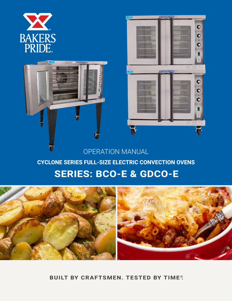
SERIES: BCO-E & GDCO-E
OPERATION MANUALCYCLONE SERIES FULL-SIZE ELECTRIC CONVECTION OVENS
ELECTRIC CONVECTION OVEN OPERATION MANUAL
Models: BCO-E and GDCO-E
ELECTRIC CONVECTION OVENS
Bakers Pride Oven Company, LLC is a wholly owned subsidiary of Standex International Corporation.
Please retain this manual for future references.
This equipment is design engineered for commercial use only.
FOR YOUR SAFETY: Do not store or use gasoline or other flammable vapors or liquids in the vicinity of this or any other appliance.
WARNING
Improper installation, adjustment, alteration, service or maintenance can cause property damage, injury or death. Read the installation, operating and maintenance instructions thoroughly before installing or servicing this equipment.
CAUTION
BAKERS PRIDE OVEN COMPANY, LLC.1307 N. Watters Rd., Suite 180
Allen, TX 75013
(972) 908-6148 Phone | (914) 576-0605 Fax | www.bakerspride.com
P/N 8898400 9/18
Initial heating of oven may generate smoke or fumes and must be done in a well-ventilated area. Overexposure to smoke or fumes may cause nausea or dizziness.
WARNING
California Residents Only
WARNING: This product can expose you to chemicals including chromium which is known to the State of California to cause cancer and birth defects or other reproductive harm. For more information go to www.P65Warnings.ca.gov.
WARNING
TABLE OF CONTENTS
1
ELECTRIC CONVECTION OVEN OPERATION MANUAL
INSTALLATION INSTRUCTIONS 1RECEIVING 1SET-UP/MOUNTING 1INSTALLATION WITH CASTERS 2LOCATION & MINIMUM CLEARANCES 2ELECTRICAL CONNECTIONS 3FLUE CONNECTION VENTILATION 3INITIAL CLEANING 4SYSTEM CHECK – ROTARY CONTROLS 4OPERATING INSTRUCTIONS 4GENERAL INSTRUCTIONS 4OPERATION SEQUENCE FOR ROTARY CONTROLS 4COOK ONLY 4TIMED COOKING 5COOK & HOLD 5STEAM INJECTION (OPTIONAL) 5OVEN COOL DOWN 5C&H-3 PUSH BUTTON CONTROL 6OPERATING 8OPTIONAL STEAM INJECTION 8OVEN COOL DOWN 8OPERATING NOTES 8STARTING A COOK CYCLE 8HOLDING TIMERS 8 DISPLAY DISCRIPTIONS 8CONTROLLER FEATURES 9
FAHRENHEIT OR CELCIUS TEMPREATURE DISPLAY 9PROGRAMMABLE TIMES 9PROGRAMMABLE TEMPERATURES 9 PROGRAMMABLE HOLD19PROGRAMMABLE FAN 9FLASHING DISPLAY 9PROGRAMMING THE OVEN CONTROLLER 10CLEANING 11SERVICING 12OPEN RACK ASS’Y INSTRUCTIONS 13STACKING INSTRUCTIONS 14LEG ASSEMBLY INSTRUCTIONS 14HELPFUL HINTS 15TROUBLESHOOTING CHART 15WIRING DIAGRAMS SINGLE PHASE 208V/240V WIRING DIAGRAM (DIAL CONTROL) 16THREE PHASE 208V/240V WIRING DIAGRAM (DIAL CONTROL) 16SINGLE PHASE 208V/240V WIRING DIAGRAM (PUSH-BUTTON CONTROL) 17THREE PHASE 208V/240V WIRING DIAGRAM (PUSH-BUTTON CONTROL) 17THREE PHASE 230V/400V (EXPORT ONLY) WIRING DIAGRAM (DIAL CONTROL) 18WARRANTY 19
INSTALLATION INSTRUCTIONSReceivingRead the notice on the outside carton regarding damage in transit. Damage discovered after opening the carton is “CONCEALED DAMAGE.” Carrier must be notified immediately to send an inspector and to furnish forms for claims against the carrier.
When the oven arrives, it should consist of:
• A crate or carton containing your new oven (two for a stacked unit).
• A carton containing four 31” legs with mounting hardware (set of four 6” legs is supplied for stacked installations).
• A carton containing a Flue Adapter and a Draft Hood. Optional: for Direct Venting (Not available for European Community Countries).
Set Up / Mounting
Your oven will be packed sitting on its bottom. The skid may be left under the oven for convenience in further handling. Unpack carefully, avoiding damage to the Stainless Steel front and/or trim. If concealed damage is found, follow the instructions detailed in Section A (Receiving). Keep the area around the ovens free and clear of combustible materials. Do not store any materials on top of or under any oven. The provision of adequate air supply to your oven for ventilation is essential. As a minimum, observe the clearances detailed in Location Section. Provide adequate ventilation and make up air in accordance with local codes.
This appliance must be installed by competent personnel in accordance with the rules in force.
NOTICE
ELECTRIC CONVECTION OVEN OPERATION MANUAL
2
INSTALLATION INSTRUCTIONS
Servicing your oven is done through the front control panel and right side access cover. Ensure that these areas are kept unobstructed for easy access.
For a single unit: Refer to Figure 4
(1) Tilt oven over to left-hand side and attach two 31” legs on the right-hand side with four 3/8-16 bolts and washers. Tighten firmly.
(2) Using proper lifting equipment, lift up the left-hand side and attach two 31” legs on the left-hand side the same way.
For a stack of two ovens: Refer to Figure 3
(1) Remove flue from top oven and replace with flue-adaptor supplied in the stacking kit.
(2) Tilt lower unit over to the left side and position two 6” legs on the right side (one for front and one for back), secure in place by using 4 bolts (3/8-16) per leg. Tighten firmly.
(3) Using proper lifting equipment, lift up the left side of the unit and attach the other two legs in the same way.
(4) Using the lifting equipment, raise the top oven to proper height and slide onto top of the bottom oven. Line up sides and front and fasten to each other at the rear of the units by using a mounting bracket supplied in the stacking kit.
To assemble an open rack stand: Refer to Figure 2.
(1) Loosen 12 bolts (attaching 31” legs) slightly.
(2) Remove 4 inner bolts, 1 from each of the 4 legs, place top right angle and top left angle underneath and tighten these 4 bolts.
(3) Insert “Open Rack Shelf” and tighten into place with eight 3/8-16 screws, washers and nuts.
(4) Position “Rack Supports” and tighten in place using 4 each of flat washers and 5/16-18 hex nuts.
Installation With Casters (Optional):Four casters (two with wheel brakes) and the mounting hardware are packed and included in the shipment if ordered. Install casters with wheel brakes on the front of the unit. Installation must conform to UL 197: Electrical Supply Connections for Permanently Connected Appliances. It requires that permanently connected appliances with casters be provided with a means for securing the appliance to the building structure to limit the movement of the appliance.
Oven Restraint: When casters are installed on either a single or double unit, a fixed restraint must be used to limit the movement of the appliance without depending on or transmitting stress to the electrical conduit. The restraint (a heavy-gauge cable) should be attached to the rear legs of the oven on which casters are mounted. If disconnection of the restraint is necessary, the restraint must be reconnected after the oven has been repositioned in its permanent location. The appliance shall be installed using flexible conduit.
Location And Minimum Clearances:Move the oven to its final location keeping the minimum clearance from the back of the oven to the wall. This clearance is necessary for safe operation and to provide proper air flow.
Minimum Clearances from Combustible and Non-combustible Construction
Under Ventilation HoodRIGHT WALL 1”LEFT WALL 1”REAR WALL 3”
Suitable for installation on combustible floor when installed with legs or casters provided.
CAUTION
Do not set the oven with its back flat against the wall. It will not operate properly unless there is at least three inches breathing space behind the oven.
CAUTION
Local codes regarding installation vary greatly from one area to another. The National Fire Protection Association, Inc., states in its NFPA 96 latest edition that local codes are “authority having jurisdiction” when it comes to requirements for installation of equipment. Therefore, installations should comply with all local codes.
NOTICE
ELECTRIC CONVECTION OVEN OPERATION MANUAL
3
INSTALLATION INSTRUCTIONS
Electrical Connection:Install according to the spacing requirements listed in the installation section of this manual. We strongly recommend having a competent professional install this equipment. A licensed electrician should make the electrical connections and connect power to the unit. Local codes should always be used when connecting these units to electrical power. In the absence of local codes, use the latest version of the National Electrical Code.
The oven, when installed, must be electrically grounded in accordance with local codes and/or the latest edition of the National Electrical Code ANSI/NFPA No. 70 in the USA (Canadian Electrical Code CSA Standard C22.1, Part 1 in Canada).
Note: For supply connections use No. 6 AWG wires suitable for at least 90°C.
NOTICE
In Europe, the appliance must be connected by an earthen cable to all other units in the complete installation and, thence, to an independent earth connection in compliance with EN 60335-1 and/or local codes.
Electrical power is to be supplied to the oven(s) by means of hard wiring, which is to be performed by a qualified licensed electrician.
a) Adequate means must be provided to limit the movement of the appliance without depending on or transmitting stress to the electrical conduit.
b) The location(s) where restraining means are to be attached to the appliance shall be specified.
c) The appliance shall be installed using flexible conduit.
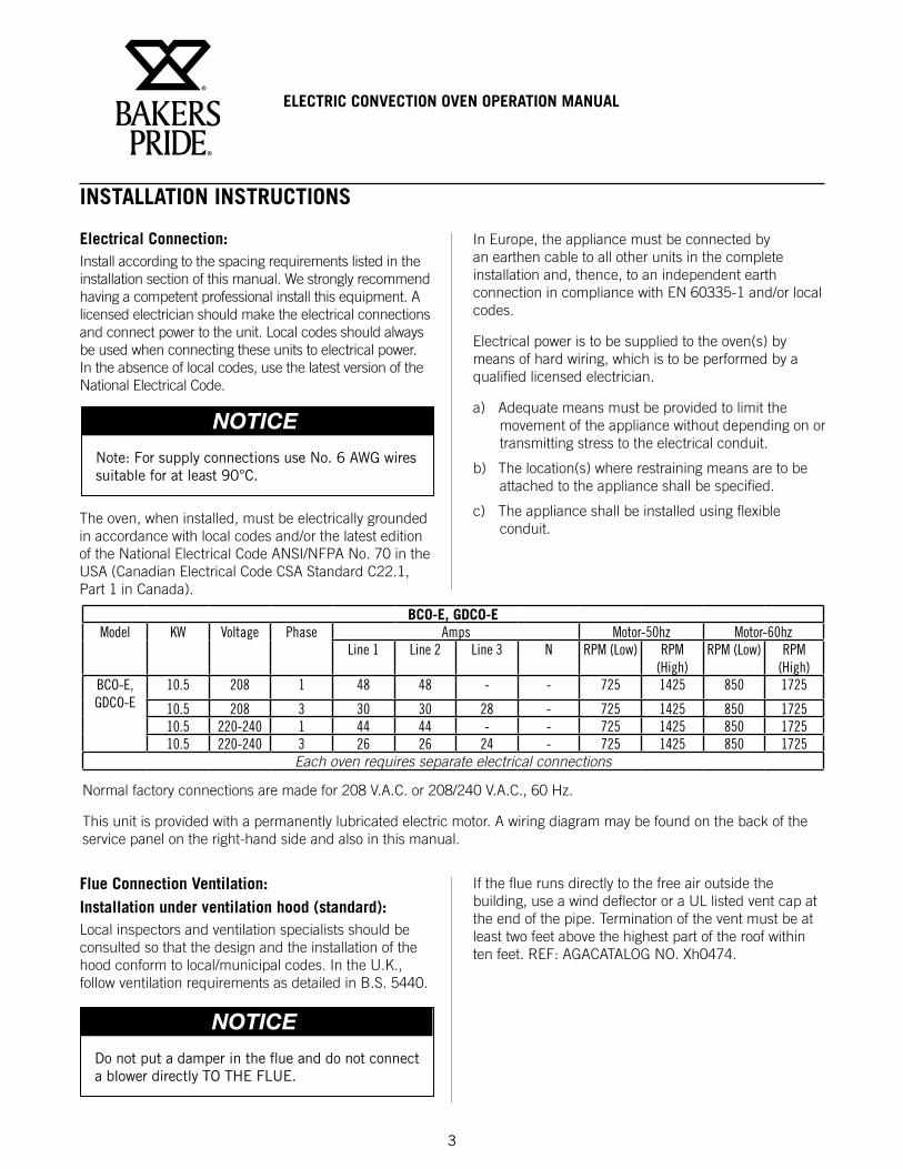
BCO-E, GDCO-EModel KW Voltage Phase Amps Motor-50hz Motor-60hz
Line 1 Line 2 Line 3 N RPM (Low) RPM (High)
RPM (Low) RPM (High)
BCO-E, GDCO-E
10.5 208 1 48 48 - - 725 1425 850 1725
10.5 208 3 30 30 28 - 725 1425 850 172510.5 220-240 1 44 44 - - 725 1425 850 172510.5 220-240 3 26 26 24 - 725 1425 850 1725
Each oven requires separate electrical connections
Normal factory connections are made for 208 V.A.C. or 208/240 V.A.C., 60 Hz.
This unit is provided with a permanently lubricated electric motor. A wiring diagram may be found on the back of the service panel on the right-hand side and also in this manual.
Flue Connection Ventilation:Installation under ventilation hood (standard):Local inspectors and ventilation specialists should be consulted so that the design and the installation of the hood conform to local/municipal codes. In the U.K., follow ventilation requirements as detailed in B.S. 5440.
Do not put a damper in the flue and do not connect a blower directly TO THE FLUE.
NOTICE
If the flue runs directly to the free air outside the building, use a wind deflector or a UL listed vent cap at the end of the pipe. Termination of the vent must be at least two feet above the highest part of the roof within ten feet. REF: AGACATALOG NO. Xh0474.
ELECTRIC CONVECTION OVEN OPERATION MANUAL
4
INSTALLATION INSTRUCTIONS
Initial Cleaning:Always clean equipment thoroughly before first use. Clean the protective oil from the metal parts and interior of baking chamber with a solution of washing soda or the other grease dissolving material.
System Check- Rotary Control (Standard):(1) Open the oven door.
(2) Turn Selector Switch to “HI.” The green indicator light near Selector Switch and oven light will illuminate.
(3) Close the door. Oven lights will go off and fan will run. Make sure fan is rotating clockwise looking from front.
(4) Press Oven Light switch. Oven light will go on and will go off as switch is released.
(5) Turn the thermostat knob. The amber indicator light near the thermostat will illuminate and the heating elements will come on.
(6) Turn the timer knob past 10 minutes and back to 2 minutes. At the end of 2 minutes the buzzer will sound. Reset by turning to “0.” All settings below 10 minutes require turning past 10 minutes and then back to the time required.
(7) Open the oven doors. Oven lights will go on and elements and fan will go off.
(8) Turn Selector Switch to “Cool Down” position. The fan will run to cool down the oven.
(9) Turn Selector Switch to “0” position.
(10) Close the oven doors.
Programming Menus: See Operating/Programming Instruction Booklet for Programmable Oven Control with Bakers Pride Software for Cyclone Series Convection Ovens supplied with this option.
With the doors closed, the power switch “on” and the selector switch is in any position other than “0”, the oven will start heating as soon as the set temperature is higher than the oven temperature.
Thermostat indicator light goes out when oven reaches set temperature and comes on when oven is heating up.
In the event of power failure, the oven will not operate.
NOTICE
OPERATING INSTRUCTIONS
General Instructions:(1) This equipment has an Electronic Temperature
Control.
(2) Due to increased efficiency of this oven, the temperature of standard recipes may be reduced 50°F (30°C).
(3) Always load each shelf evenly. Space pans away from each other and from sides and back of oven to allow maximum air flow between them.
(4) Large tempered glass windows and interior lights allow a close check on the product making it unnecessary to frequently open the doors. Products cook faster in a convection oven as compared to a conventional oven. Depending on the product and the type of pans used, time saving may run from 20 percent to as high as 50 percent.
Operation Sequence Rotary Control:Cook only rotary control:(1) Close the oven doors.
(2) Turn Selector Switch to “HI” or “LO” position. The indicator light near the Selector Switch will be illuminated.
(3) Turn the thermostat knob to the desired cooking temperature.
(4) Upon reaching the set temperature, the indicator light near the thermostat will go out.
(5) Load the oven with product to be cooked.
(6) Remove the product from the oven when done.
ELECTRIC CONVECTION OVEN OPERATION MANUAL
5
OPERATING INSTRUCTIONS
Timed cooking rotary control:(1) Close the oven doors.
(2) Turn Selector Switch to “HI” or “LO” position. The indicator light near the Selector Switch will be illuminated.
(3) Turn the thermostat knob to the desired cooking temperature.
(4) Upon reaching the set temperature, the indicator light near the thermostat will go out.
(5) Load the oven with product to be cooked.
(6) Turn the timer knob to the desired bake time and timer will start counting down.
(7) When timer reaches zero, a buzzer will sound.
(8) Turn the timer knob to “O” position.
(9) Remove the product from the oven.
Cook and Hold Rotary Control:(1) Close the oven doors.
(2) Turn Selector Switch to “HI” or “LO” position. The indicator light near the Selector Switch will be illuminated.
(3) Turn the thermostat knob to the desired cooking temperature.
(4) Upon reaching the set temperature, the indicator light near the thermostat will go out.
(5) Load the oven with product to be cooked.
(6) Turn the timer knob to the desired bake time and timer will start counting down.
(7) When timer reaches zero, a buzzer will sound.
(8) Turn the Timer knob to “O” position.
(9) Turn the thermostat knob to the desired hold temperature.
(10) Remove the product from the oven when done.
Timer does not control the oven.
NOTICE
Optional steam injection Rotary control:The solenoid valve for steam injection is mounted behind the service panel on the right-hand side of the unit. The electronic timer is preset at the factory. A 1/4” copper tubing is provided on the Solenoid Valve for water hookup with a compression fitting. After the water hookup is made, make sure that there are no leaks. For steam injection, press the Steam switch momentarily.
Oven cool down Rotary control:To cool down the oven to a lower desired temperature, follow the steps detailed below.
(1) Open the oven doors.
(2) Turn Selector Switch to “oven cool down” position. Fan will now operate and cool down the oven.
(3) When the oven has cooled down to the desired temperature, turn the Selector Switch to “O” position. Close oven doors.
Do not use steam injection at temperatures below 275°F (135°C).
NOTICE
ELECTRIC CONVECTION OVEN OPERATION MANUAL
6
OPERATING INSTRUCTIONS
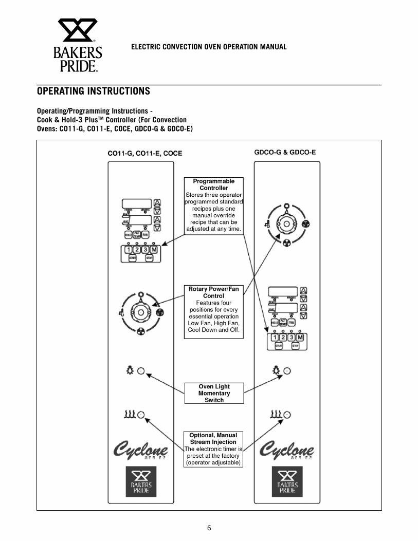
Operating/Programming Instructions - Cook & Hold-3 PlusTM Controller (For Convection Ovens: CO11-G, CO11-E, COCE, GDCO-G & GDCO-E)
ELECTRIC CONVECTION OVEN OPERATION MANUAL
7
OPERATING INSTRUCTIONS
ELECTRIC CONVECTION OVEN OPERATION MANUAL
8
OPERATING INSTRUCTIONS
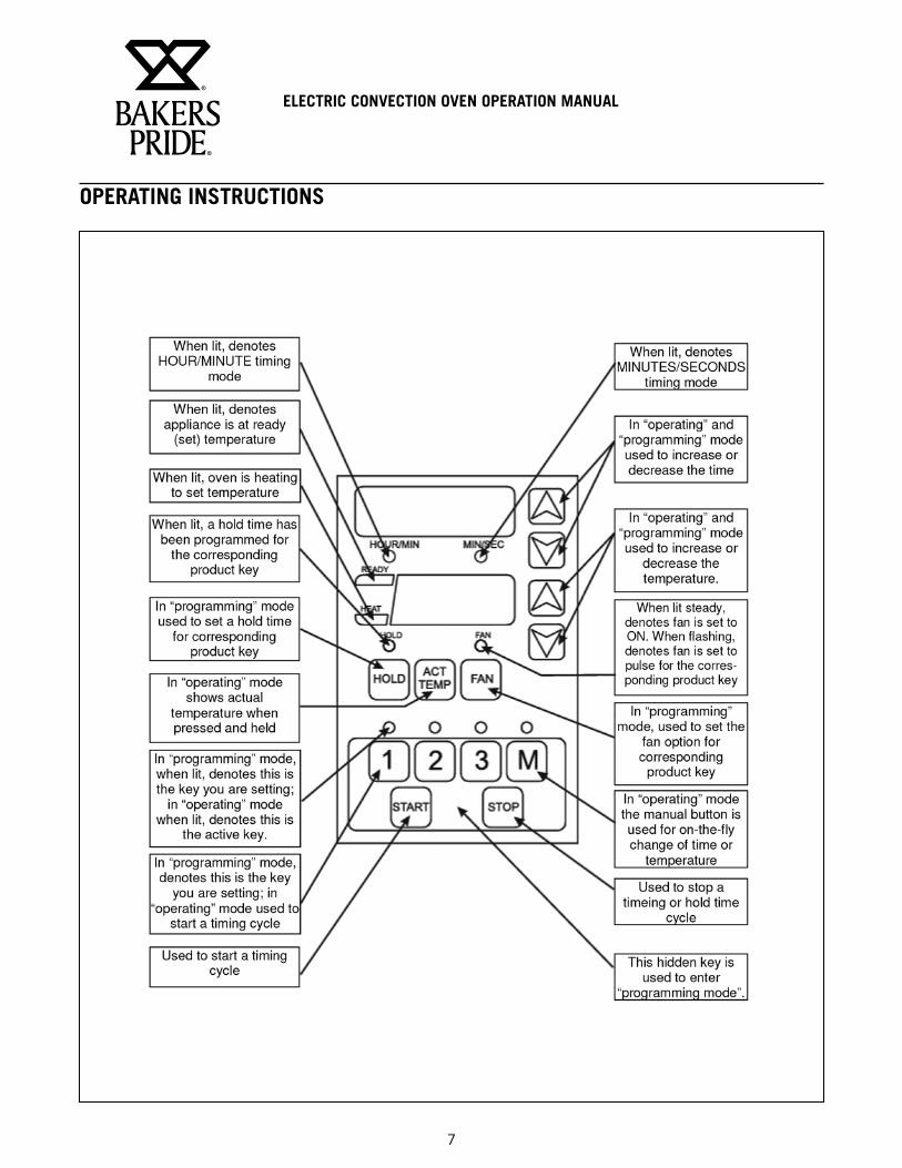
Operating InstructionsThere are 3 programmable times & temperatures, and 1 manual override time & temperature setting. The timing range of all keys is from: 01 second to 99 hours (automatically switches from min/sec. to hour/min). Each key is also programmable for one hold time and a two-position fan (on/pulse).
In normal operating mode, the READY LIGHT (LED) will illuminate when the oven temperature is +20°F of set temperature. The HEAT LIGHT (LED) will illuminate when actual temperature is below set temperature and the unit is calling for heat.
Once set and actual temperatures are equal, key 1, 2, 3 or M may be pressed. The light above the corresponding key will be lit. Pressing the START key will begin a flex time countdown (time is compensating) depending on temperature.
Optional Steam InjectionThe solenoid valve for steam injection is mounted behind the service panel on the right-hand side of the unit on COC-E and on back of the unit on C011 -E/G. The electronic timer is pre-set at the factory and may be adjusted by operator if required for shorter or longer steam burst. For steam injection, press the steam injection switch.
Oven Cool DownTo cool down the oven to a lower desired temperature, follow the steps detailed below: Open the oven door(s). Turn selector switch to “Oven Cool Down” position. Fan will now operate and cool down the oven. When the oven has cooled to the desired temperature, turn the selector switch to the “0” position.
Operating NotesWhen the oven is turned on it will automatically preheat to set temperature if the door is closed. If the door is opened while program is running, the cook cycle will pause and the display will flash. When the door is closed, the display will return to the count down from where it was paused.
Starting A Cook CycleTo start a cook cycle, simply turn selector switch to LO or HI position and press the product key for the product you wish to cook. If the product key is programmed, the correct cooking time
will be displayed 12:00 (example). Press the START key and the time will immediately start to count down in minutes and seconds. If: 00 is displayed immediately and the unit starts to signal, the key being operated is not programmed. If correctly programmed, it will count down to :00. When zero is reached, the light above the product key will be flashing, the controller will emit an audible alarm and immediately begin counting up (if programmed for a hold time).
Cancel this alarm by pressing the stop key; controller will continue to count up.
Holding TimersIf the unit is programmed with a holding time, the holding time will automatically start counting upon expiration of the cooking cycle. When there is an active hold time, the HOLD indicator will be lit and the light above the product key with the hold time will be flashing.
To cancel, press the key.
Display DescriptionsThe unit is in the Operating Mode. The actual temperature is shown in the display and is within 20 degrees of the programmed temperature.
The unit is in the Operating Mode. The actual temperature will flash in the display and is more than 20 degrees below the programmed temperature range.
The unit is in the Operating Mode. The flashing display signifies a cook cycle has just been completed.
The unit is in the Operating Mode. With three zeros displayed, the probe has failed, or the appliance has gone beyond operating temperature. Shut the appliance OFF immediately and call a technician.
ELECTRIC CONVECTION OVEN OPERATION MANUAL
9
OPERATING INSTRUCTIONS
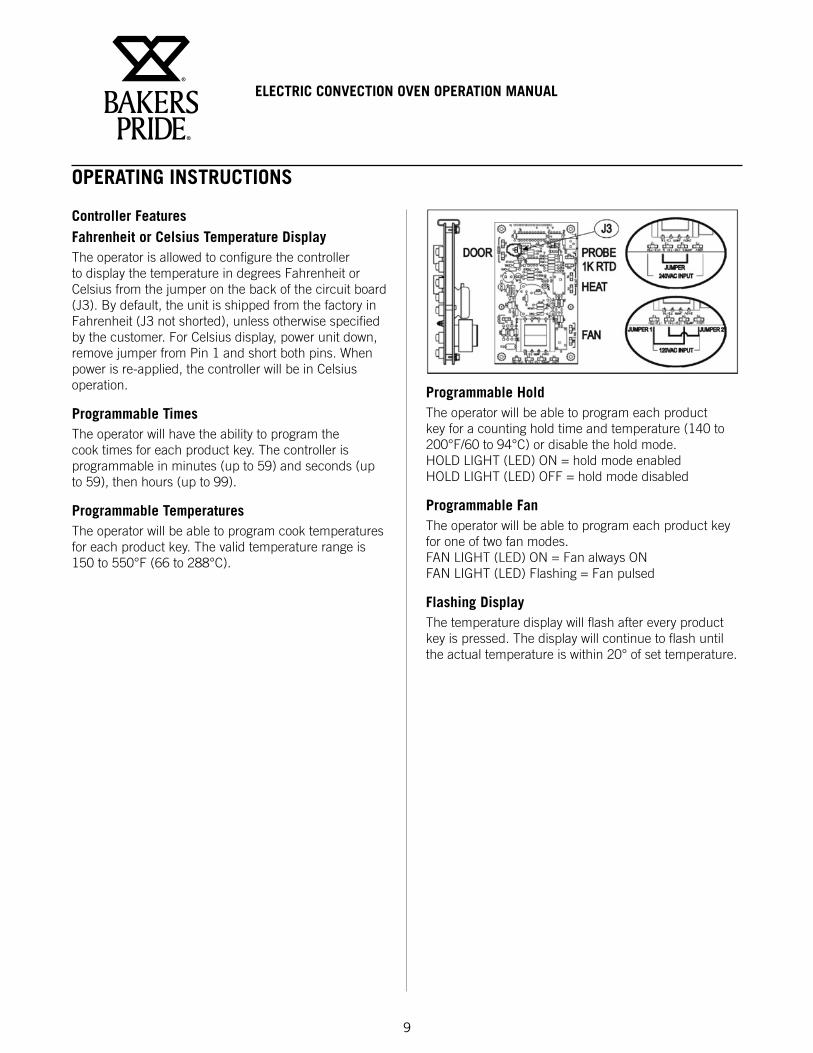
Controller FeaturesFahrenheit or Celsius Temperature DisplayThe operator is allowed to configure the controller to display the temperature in degrees Fahrenheit or Celsius from the jumper on the back of the circuit board (J3). By default, the unit is shipped from the factory in Fahrenheit (J3 not shorted), unless otherwise specified by the customer. For Celsius display, power unit down, remove jumper from Pin 1 and short both pins. When power is re-applied, the controller will be in Celsius operation.
Programmable TimesThe operator will have the ability to program the cook times for each product key. The controller is programmable in minutes (up to 59) and seconds (up to 59), then hours (up to 99).
Programmable TemperaturesThe operator will be able to program cook temperatures for each product key. The valid temperature range is 150 to 550°F (66 to 288°C).
Programmable HoldThe operator will be able to program each product key for a counting hold time and temperature (140 to 200°F/60 to 94°C) or disable the hold mode. HOLD LIGHT (LED) ON = hold mode enabled HOLD LIGHT (LED) OFF = hold mode disabled
Programmable FanThe operator will be able to program each product key for one of two fan modes. FAN LIGHT (LED) ON = Fan always ON FAN LIGHT (LED) Flashing = Fan pulsed
Flashing DisplayThe temperature display will flash after every product key is pressed. The display will continue to flash until the actual temperature is within 20° of set temperature.
ELECTRIC CONVECTION OVEN OPERATION MANUAL
10
OPERATING INSTRUCTIONS
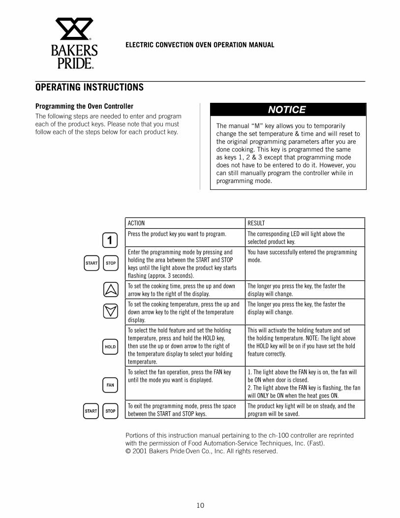
Programming the Oven ControllerThe following steps are needed to enter and program each of the product keys. Please note that you must follow each of the steps below for each product key.
The manual “M” key allows you to temporarily change the set temperature & time and will reset to the original programming parameters after you are done cooking. This key is programmed the same as keys 1, 2 & 3 except that programming mode does not have to be entered to do it. However, you can still manually program the controller while in programming mode.
NOTICE
ACTION RESULT
Press the product key you want to program. The corresponding LED will light above the selected product key.
Enter the programming mode by pressing and holding the area between the START and STOP keys until the light above the product key starts flashing (approx. 3 seconds).
You have successfully entered the programming mode.
To set the cooking time, press the up and down arrow key to the right of the display.
The longer you press the key, the faster the display will change.
To set the cooking temperature, press the up and down arrow key to the right of the temperature display.
The longer you press the key, the faster the display will change.
To select the hold feature and set the holding temperature, press and hold the HOLD key, then use the up or down arrow to the right of the temperature display to select your holding temperature.
This will activate the holding feature and set the holding temperature. NOTE: The light above the HOLD key will be on if you have set the hold feature correctly.
To select the fan operation, press the FAN key until the mode you want is displayed.
1. The light above the FAN key is on, the fan will be ON when door is closed. 2. The light above the FAN key is flashing, the fan will ONLY be ON when the heat goes ON.
To exit the programming mode, press the space between the START and STOP keys.
The product key light will be on steady, and the program will be saved.
Portions of this instruction manual pertaining to the ch-100 controller are reprinted with the permission of Food Automation-Service Techniques, Inc. (Fast). © 2001 Bakers Pride Oven Co., Inc. All rights reserved.
ELECTRIC CONVECTION OVEN OPERATION MANUAL
11
OPERATING INSTRUCTIONS
CleaningAlways clean equipment thoroughly before first use. Clean unit daily.
Clean The Stainless Steel Interior:Baked on splatter, oil, grease or discoloration on the stainless steel inside of the oven may be removed with stainless steel cleaner, or any other similar cleaning agent. NEVER use vinegar or any corrosive cleaner. Use only cleaners approved for stainless steel. NEVER use cleaning solvents with a hydrocarbon base. NEVER use a wire brush, steel or abrasive scouring pads, scraper, file or other steel tools. NOTE: ALWAYS RUB THE STAINLESS STEEL ALONG THE GRAINS.
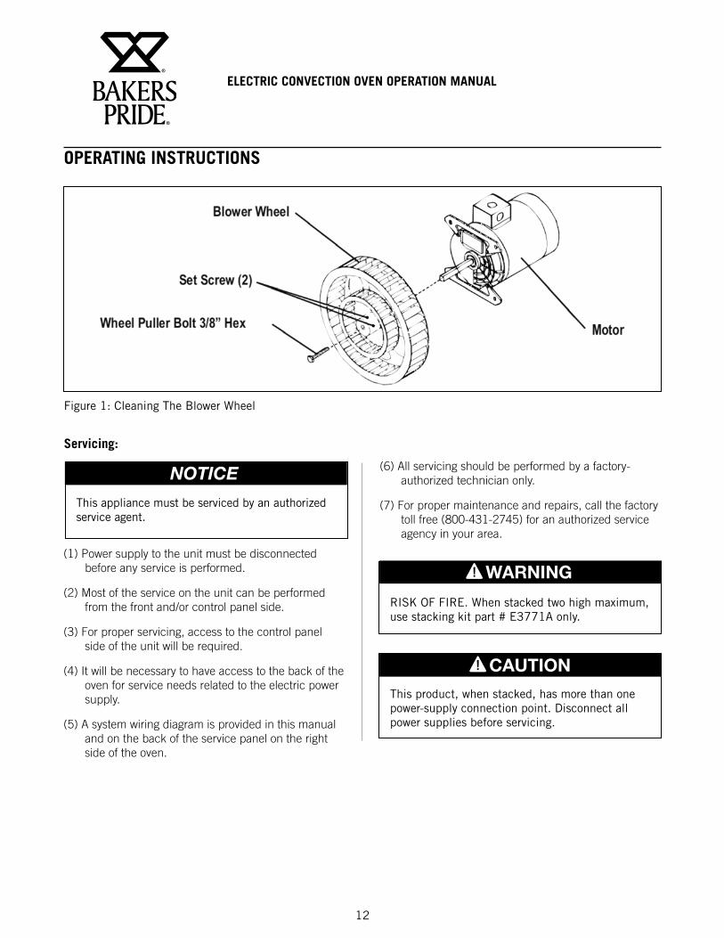
Clean The Blower Wheel:To clean the blower wheel, remove and immerse in ammoniated water for 20 to 25 minutes. Then, scrub it off with a small, stiff brush. The same procedure can be followed for wire racks and rack supports. To remove the blower wheel, loosen the set screws (2) on the hub of the blower wheel and tighten the 3/8” wheel puller bolt (supplied) in center of hub (See Fig. 1).
Clean The Porcelain Interior:Porcelain enamel interiors are designed to be as maintenance free as possible. However, for best results, the oven should be cleaned regularly. Enameled interiors can be easily cleaned with oven cleaners. Keep cleaning fluids away from electrical wires, light sockets, switches and control panel.
Oven Exterior:Clean The Exterior Stainless Steel:To remove normal dirt or product residue from stainless steel, use ordinary soap and water (with or without detergent) applied with a sponge or cloth. Dry thoroughly with a clean cloth. Never use vinegar or corrosive cleaner. Do not use chorine based cleaners.
To remove grease and food splatter or condensed vapors that have baked on the equipment, apply cleaners to a damp cloth or sponge and rub cleanser on the metal in the direction of the polished lines on the metal. Rubbing cleanser as gently as possible in the direction of the polished lines will not mar the finish of the stainless steel. To remove discoloration, use a non-abrasive cleaner. NEVER use a wire brush, steel or abrasive scouring pads, scraper, file or other steel tools. Never rub with a circular motion.
Use mild detergent or soap solution for best results. Abrasive cleaners could scratch the finish of your unit, marring it’s appearance and making it susceptible to dirt accumulation. DO NOT use abrasive cleaners or cleaners/sanitizers containing chlorine, iodine, ammonia or bromine chemicals as these will deteriorate the stainless steel and glass material and shorten the life of the unit. Use nylon scouring pads. DO NOT use steel wool.
CAUTION
To avoid any injury, turn the power switch off at the fuse disconnect switch/circuit breaker or unplug the unit from the power source and allow to cool completely before performing any maintenance or cleaning.
WARNING
Unit is not waterproof. To avoid electrical shock or personal injury, DO NOT submerge in water. DO NOT operate if it has been submerged in water. DO NOT clean the unit with a water jet. DO NOT steam clean or use excessive water on the unit.
WARNING
Oven Interior:Clean The Racks And Rack Support Guides:Open the doors and remove all wire racks and rack support guides. Take them to the sink and thoroughly clean in warm water with mild detergent or soap. Use a nylon scouring pad or stiff nylon brush.
DO NOT USE STEEL WOOL.
ELECTRIC CONVECTION OVEN OPERATION MANUAL
12
Figure 1: Cleaning The Blower Wheel
OPERATING INSTRUCTIONS
Servicing:
(1) Power supply to the unit must be disconnected before any service is performed.
(2) Most of the service on the unit can be performed from the front and/or control panel side.
(3) For proper servicing, access to the control panel side of the unit will be required.
(4) It will be necessary to have access to the back of the oven for service needs related to the electric power supply.
(5) A system wiring diagram is provided in this manual and on the back of the service panel on the right side of the oven.
This appliance must be serviced by an authorized service agent.
NOTICE (6) All servicing should be performed by a factory-authorized technician only.
(7) For proper maintenance and repairs, call the factory toll free (800-431-2745) for an authorized service agency in your area.
This product, when stacked, has more than one power-supply connection point. Disconnect all power supplies before servicing.
CAUTION
RISK OF FIRE. When stacked two high maximum, use stacking kit part # E3771A only.
WARNING
ELECTRIC CONVECTION OVEN OPERATION MANUAL
13
OPERATING INSTRUCTIONS
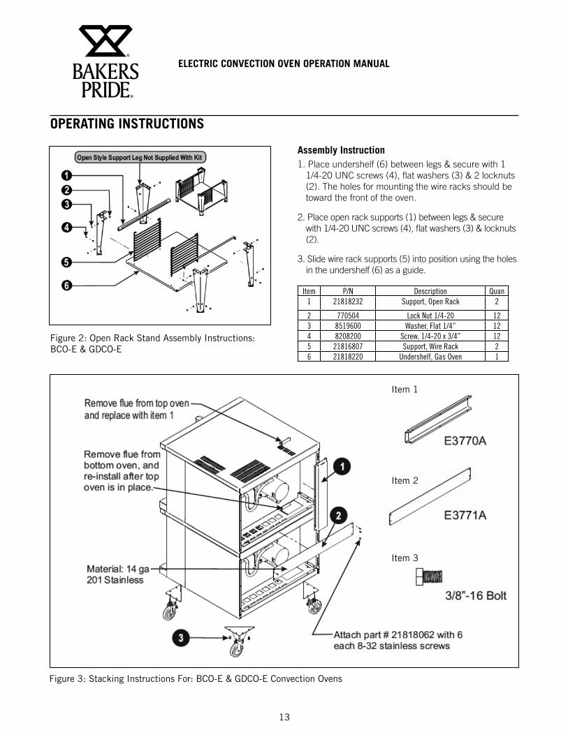
Figure 2: Open Rack Stand Assembly Instructions: BCO-E & GDCO-E
Assembly Instruction1. Place undershelf (6) between legs & secure with 1
1/4-20 UNC screws (4), flat washers (3) & 2 locknuts (2). The holes for mounting the wire racks should be toward the front of the oven.
2. Place open rack supports (1) between legs & secure with 1/4-20 UNC screws (4), flat washers (3) & locknuts (2).
3. Slide wire rack supports (5) into position using the holes in the undershelf (6) as a guide.
Item P/N Description Quan1 21818232 Support, Open Rack 2
2 770504 Lock Nut 1/4-20 123 8519600 Washer, Flat 1/4” 124 8208200 Screw, 1/4-20 x 3/4” 125 21816807 Support, Wire Rack 26 21818220 Undershelf, Gas Oven 1
Figure 3: Stacking Instructions For: BCO-E & GDCO-E Convection Ovens
Item 1
Item 2
Item 3
ELECTRIC CONVECTION OVEN OPERATION MANUAL
14
OPERATING INSTRUCTIONS
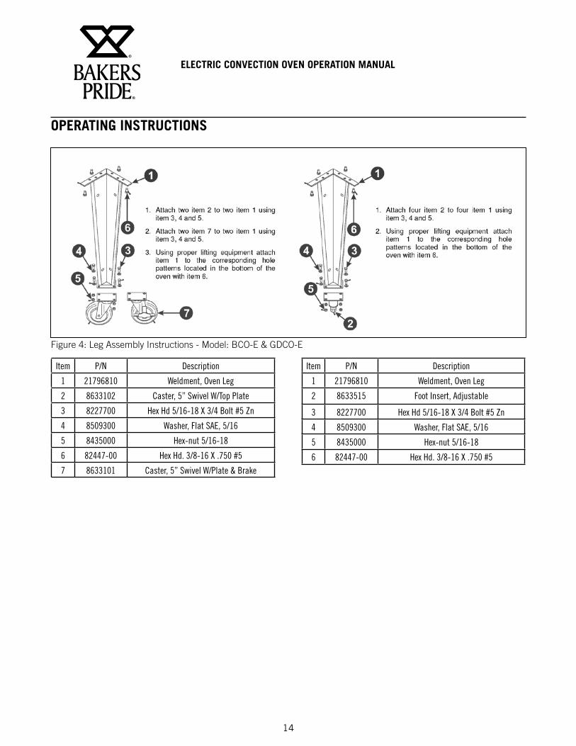
Figure 4: Leg Assembly Instructions - Model: BCO-E & GDCO-E
Item P/N Description
1 21796810 Weldment, Oven Leg
2 8633102 Caster, 5” Swivel W/Top Plate
3 8227700 Hex Hd 5/16-18 X 3/4 Bolt #5 Zn
4 8509300 Washer, Flat SAE, 5/16
5 8435000 Hex-nut 5/16-18
6 82447-00 Hex Hd. 3/8-16 X .750 #5
7 8633101 Caster, 5” Swivel W/Plate & Brake
Item P/N Description
1 21796810 Weldment, Oven Leg
2 8633515 Foot Insert, Adjustable
3 8227700 Hex Hd 5/16-18 X 3/4 Bolt #5 Zn
4 8509300 Washer, Flat SAE, 5/16
5 8435000 Hex-nut 5/16-18
6 82447-00 Hex Hd. 3/8-16 X .750 #5
ELECTRIC CONVECTION OVEN OPERATION MANUAL
15
OPERATING INSTRUCTIONS
HELPFUL HINTSPROBLEM CAUSE SOLUTION
Food browns unevenly Improper heating temperature. Preheat until desired temperature is reached.Aluminum foil on rack or oven bottom. Remove foil.Several pans crowded together. Center pans on racks, or leave more space between all pans and
oven walls.Baking pans too large. Use smaller pan.Baking pan dark or glass. Lower oven temperature 25°F (-3.8°C) for this type of pan.Temperature too low Increase temperatureTime too short Increase bake time
Food dries before browning Oven temperature too high Lower oven temperatureOven door opened too frequently Check food a minimum number of times.
Cookies too brown Oven temperature too high Lower oven temperatureDark cookie sheet Use light, shiny cookie sheet.Pans too deep Use a cookie sheet (not a baking pan).
Cookies too flat Hot cookie sheet Allow cookie sheet to cool between batches.Fan is set on high Speed Set fan to low speed
Cake too brown on bottom or crust forms on bottom
Oven temperature too high. Lower temperature; if using glass or dark pan, lower 25°F (-3.8°C)
Cakes have light outer color Thermostat set too low. Raise temperatureCake settles slightly in the center. Bake time too short or bake temperature too low. Bake longer or raise oven temperature slightly. Do not open doors
to oven for long periods.Cake ripples Overloading pans or batter is too thin Reduce pan loads. Thicken batter.Cakes are too coarse Thermostat set too high. Lower oven temperature.Pies have uneven color Too many pies per rack. Reduce number of pies per rack or eliminate use of bake pans.Cupcakes crack on top Thermostat set too high. Lower oven temperature.Meats are browned & not done in the center
Thermostat set too high. Lower oven temperature and roast longer.
Meats are well done and not browned
Thermostat set too low. Raise temperature. Limit amount of moisture.
Meats develop hard crust Thermostat set too high. Reduce temperature or place pan of water in ovenFan is set on high speed Set fan to low speed
TROUBLESHOOTING CHART
PROBLEM CAUSE SOLUTION
No heat Oven has no electrical power Check electrical supply.
Power switch on control panel is off. Set the control panel to COOK or OVEN ON.
Doors are open. Close doors.
Oven does not come to ready. The oven has not reached preheat temperature. Wait for oven to reach preheat temperature.
Internal problem with main temperature control. Call Bakers Pride factory authorized service center
Convection fan does not run. Oven has no electrical power. Check electrical supply.
Circuit breaker tripped. Reset the breaker.
Doors are open Close doors.
Door switch Call Bakers Pride factory authorized service center
ELECTRIC CONVECTION OVEN OPERATION MANUAL
16
OPERATING INSTRUCTIONS
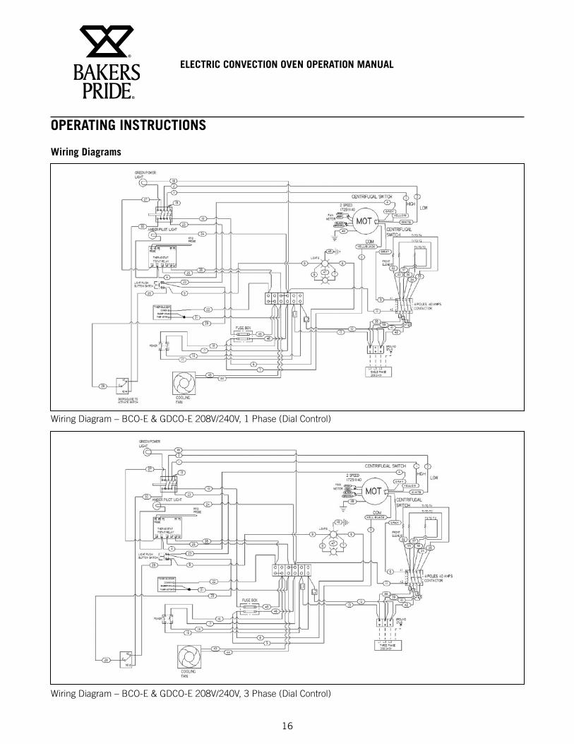
Wiring Diagrams
Wiring Diagram – BCO-E & GDCO-E 208V/240V, 1 Phase (Dial Control)
Wiring Diagram – BCO-E & GDCO-E 208V/240V, 3 Phase (Dial Control)
ELECTRIC CONVECTION OVEN OPERATION MANUAL
17
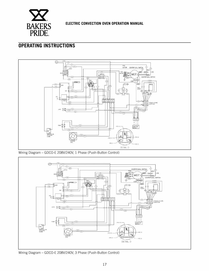
OPERATING INSTRUCTIONS
Wiring Diagram – GDCO-E 208V/240V, 1 Phase (Push-Button Control)
Wiring Diagram – GDCO-E 208V/240V, 3 Phase (Push-Button Control)
ELECTRIC CONVECTION OVEN OPERATION MANUAL
18
OPERATING INSTRUCTIONS
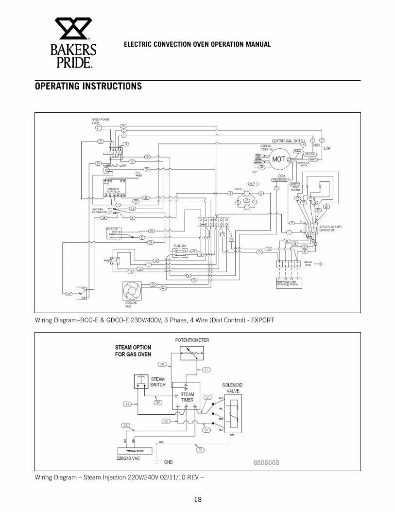
Wiring Diagram–BCO-E & GDCO-E 230V/400V, 3 Phase, 4 Wire (Dial Control) - EXPORT
Wiring Diagram – Steam Injection 220V/240V 02/11/10 REV –
ELECTRIC CONVECTION OVEN OPERATION MANUAL
19
BAKERS PRIDE LIMITED WARRANTYWHAT IS COVERED This warranty covers defects in material and workmanship under normal use, and applies only to the original purchaser
providing that:
• The equipment has not been accidentally or intentionally damaged, altered or misused;
• The equipment is properly installed, adjusted, operated and maintained in accordance with National and local codes and in accordance with the installation instruction provided with the product;
• The serial number rating plate affixed to the equipment has not been defaced or removed.
WHO IS COVERED This warranty is extended to the original purchaser and applies only to equipment purchased for use in the U.S.A.
COVERAGE PERIOD Cyclone Convection Ovens: BCO Models: One (1) Year limited parts and labor; (1) Year limited door warranty.
GDCO Models: Two (2) Year limited parts and labor; (2) Year limited door warranty.
CO11 Models: Two (2) Year limited parts and labor; (5) Year limited door warranty.
All Other Products: One (1) Year limited parts and labor. Warranty period begins the date of dealer invoice to customer or ninety (90) days after shipment date from Bakers Pride - whichever comes first.
WARRANTY This warranty covers on-site labor, parts and reasonable travel time and travel expenses of the authorized service
COVERAGE Representative up to (100) miles, round trip, and (2) hours travel time. The purchaser, however, shall be responsible for all expenses related to travel, including time, mileage and shipping expenses on smaller counter models that may be carried into a Factory Authorized Service Center, including the following models: PX-14, PX-16, P18, P22S, P24S, PD-4, PDC, WS Series and BK-18.
EXCEPTIONS All removable parts in Bakers Pride® cooking equipment, including but not limited to: Burners, Grates, Radiants, Stones and Valves, are covered for a period of SIX MONTHS. All Ceramic Baking Decks are covered for a period of THREE MONTHS. The installation of these replacement decks is the responsibility of the purchaser. The extended Cyclone door warranty years 3 through 5 is a parts only warranty and does not include labor, travel, mileage or any other charges.
EXCLUSIONS • Negligence or acts of God,
• Failures caused by erratic voltages or gas supplies,
• Thermostat calibrations after (30) days from equipment installation date,
• Unauthorized repair by anyone other than a Bakers Pride Factory Authorized Service Center,
• Air and Gas adjustments,
• Damage in shipment,
• Light bulbs,
• Alteration, misuse or improper installation,
• Glass doors and door adjustments,
• Thermostats and safety valves with broken capillary tubes,
• Fuses,
• Char-broiler work decks and cutting boards,
• Tightening of conveyor chains,
• Adjustments to burner flames and cleaning of pilot burners,
• Tightening of screws or fasteners,
• Accessories — spatulas, forks, steak turners, grate lifters, oven brushes, scrapers, peels. etc.,
• Freight — other than normal UPS charges,
• Ordinary wear and tear.
INSTALLATION Leveling and installation of decks as well as proper installation and check out of all new equipment —per appropriate installation and use materials — is the responsibility of the dealer or installer, not the manufacturer.
REPLACEMENT PARTS Bakers Pride genuine Factory OEM parts receive a (90) day materials warranty effective from the date of installation by a Bakers Pride Factory Authorized Service Center.
This Warranty is in lieu of all other warranties, expressed or implied, and all other obligations or liabilities on the manufacturer’s part. Bakers Pride shall in no event be liable for any special, indirect or consequential damages, or in any event for damages in excess of the purchase price of the unit. The repair or replacement of proven defective parts shall constitute a fulfillment of all obligations under the terms of this warranty.
Form #U4177A 1/07
Be sure to keep up with new product announcements and events on social media!
The Standex Food Service Equipment Group (FSEG) is a manufacturer of innovative commercial food service equipment offering a wealth of refrigeration and cooking expertise. Products include walk-in coolers and freezers; hot and cold display cabinets, cases, and storage systems; commercial ovens,
rotisseries, and cooking equipment; and rotary vane pumps.
Ask your sales representative about how the power of all Standex brands can work for you.www.standex.com/segments/food-service
Food Service Equipment Group