Embed Size (px)
Citation preview

Functional optionsAdjuster optionsSymmetric Style
Cylinder with built-in guide rail and tableNow with recirculating linear ball bearingsfor high rigidity and high precisionAir slide table for precise assembly applications
Body mounting tap
High precision and compact Improved against loadsAbout 3 times stronger against unexpected excessive external forces compared with MXS series
Standardized symmetric styleAvailable for all options
Pin holes for positioning
Work mounting tap
Improved strength
Dual rod
Built-in table and guide rail
Recirculating linear ball bearing
Wide variety of options
Pin holes forpositioning
For Z axis of pickand place
Mounting groove for auto switch
Through hole for body mounting
Ample options for stroke adjustment
Applications
For positioning of pallet on a conveyor
Adjuster option and functional option are available in combination.
Double the output of previous cylinder
End plate is made of extra duralumin.(Except the buffer style)
Improved repeatability of workmounting Auto switch is mounted in recessed
groove for added protection and convenience.
Made of martensitic stainless steel
Improved repeatability of body mounting
Widened main body of linear guide block is made of martensitic stainless steel
wLateral mounting (Through hole) eVartical mounting (Body tap)
Model
MXQ12-30MXS12-30
Accuracy Dimensions
Parallelism
0.035
0.2
±0.08
±0.2
Width
46
50
Height
30
32
Length
86
80
MXQ compared with MXS (mm)
Mounting from 3 directionavailableqLateral mounting (Body tap)
With stroke adjuster
With buffer
With end lock
Axial piping
With shock absorber
Air Slide Table
ø6, ø8, ø12, ø16, ø20, ø25Series MXQ
Heighttolerance
2-179

Functional OptionsAdjuster Options
With buffer With end lock
Axial pipingSetting ON or OFF at normal status according tothe direction of the auto switch
For insertion application, buffer mechanismabsorbs the impact of a shock and protectsfrom damages if the work piece arrives at thewrong location as a result of poor alignment.
Application example
When bufferfunctioned
Normal condition
Failure inpositioning
Air gripper
Work
Buffermechanism
� Eliminates impacts at the extend strokeend to protect the work and tool.
� Auto switch is installable on the buffer section.
� Maintains the original position of the cylinderafter air pressure shut off, thus preventingthe work from falling.
� Organizes all piping into axial directions andfrees up space around the body.
Variations
Extension stroke adjuster
Retraction stroke adjuster
Auto switch∗OFF at normal status ON at buffer operating
Auto switch
Magnet
Magnet
∗ON at normal status OFF at buffer operating( )
Buffer stroke
Locked
All adjuster bolts are standardized for the extensionand retraction end stroke adjuster, and the threedifferent styles of cushion mechanisms.
� Rubber stopperStandard stroke adjuster
� Shock absorber
For heavy duty and/or high speed use.
Absorbs impact at end of stroke
Provides smooth stops
Improves accuracy when stopping
� Metal stopper
Improves stopping accuracy
For light duty and low speed use only
MXQ6L
MXQ8L
MXQ12L
MXQ16L
MXQ20L
MXQ25L
MXQ 6
MXQ 8
MXQ12
MXQ16
MXQ20
MXQ25
Standard Symmetric
Model
�
�
�
�
�
�
�
�
�
�
�
�
�
�
�
�
�
�
�
�
�
�
�
�
�
�
�
�
�
�
�
�
�
�
�
�
�
�
�
�
�
�
�
�
�
�
�
�
�
�
�
�
�
�
�
�
�
�
�
�
�
�
�
�
�
�
�
�
�
�
�
�
�
�
�
�
�
�
�
�
�
�
�
�
�
�
�
�
�
�
�
�
�
�
�
�
�
�
�
�
�
�
�
�
�
�
�
�
�
�
�
�
10 20 30 40 50 75 100 125 150
Rear
end
Both
end
Fron
t end
Fron
t end
Fron
t end
Rear
end
Both
end
Rear
end
Both
end
Buffe
r
End
lock
Axia
l pip
ingRubber
stopperShockabsorber
Metalstopper
Adjuster optionsStandard stroke (mm)
Functional options
Auto switch
Bor
e (m
m)
Reed switchD-A9D-A9 � VSolid state switchD-M9 �D-M9 � V2 color indicationsolid state switchD-M9 �D-M9 � WV
6
8
12
16
20
25
Lock pistonSpring
Unlocked
Supply portto cylinder
Speed controller
( )
2-180
Series MXQ

Mounting
CautionqDo not apply a load beyond the
range of the operation limits.Select the model by using the maximum allowable load and allowable moment. Refer to pages p.2-190 for details. When an actuator is used beyond its operating limits, eccentric loads on the guide section will be in excess which results in shorter life span due to play or inaccuracy of guide section.
w If a table is stopped at an intermediate position by an external stopper, avoid ejection.If ejection occurs, it causes damage. If a slide table is stopped at an intermediate position by an external stopper and then forwarded to the front, draw back the intermediate stopper after supplying pressure to allow the slide table to return to the back for an instant, then supply pressure to the opposite port to operate the slide table.
eDo not use in circumstances that excessive, external forces or impacts would be applied.These conditions could lead to malfunctions.
Selection
CautionqDo not scratch or dent the
mounting side of the body, table or end plate.Decreasing flatness on the mounting surface causes play in the guide section and increases sliding resistance.
wDo not scratch or dent on the forward side of the rail or guide.It can generation play in the guide section and increase sliding resistance.
eDo not apply excessive impacts or moments when a work is mounted.If external load beyond the specified allowable moment is applied, it generates play in the guide section and increases sliding resistance.
rFlatness of mounting surface should be 0.02mm or less.Insufficient flatness of work piece of base to which an air slide table is mounted can generates play in the guide section and increase sliding resistance.
tWhen connecting with loads which has external support or external guide mechanism, select the connection and align properly.
yTake care to prevent contact with objects such as a hand while an air slide table is in operation.A hand can be caught by an adjuster. Install a protection cover if anything could interfere during its operation.
uDo not bring into close contact with objects which would be influenced by magnetic fields.As an air slide table has magnets built-in, do not allow close contact with magnetic disks, magnetic cards or magnetic tapes. Data may be erased.
iWhen mounting an air slide table, screws of appropriate length should be used and tightened properly within the maximum tightening torque.If screws are tightened beyond designed limits, malfunction may occur. If they are tightened insufficiently, it may result in sliding of falling off from its position.
Model
MXQ 6MXQ 8MXQ12MXQ16MXQ20MXQ25
Boltused
M4M4M5M6M6M8
Max.tighteningtorque Nm
2.1 2.1 4.4 7.4 7.418
Max.screw-indepth (l mm)
Max.tighteningtorque Nm
Max.screw-indepth (l mm)
8 810121216
1. Side body tapped
Model
MXQ 6MXQ 8MXQ12MXQ16MXQ20MXQ25
Boltused
M3M3M4M5M5M6
1.2 1.2 2.8 5.7 5.710
l mm
10.512.516212632
2. Side through hole mounting
Model
MXQ 6MXQ 8MXQ12MXQ16MXQ20MXQ25
Boltused
M2.5M3M4M5M5M6
0.50.92.14.44.47.4
44678
10
3. Top body tapped
ll
l
Series MXQ/Precautions qBe sure to read before handling.
Max.tighteningtorque Nm
2-181

Mounting
Series MXQ/Precautions wBe sure to read before handling.
qDo not use in an environment exposed directly to liquids such as cutting oil.If used in an environment exposed to cutting oil, coolant or oil mist, it generates play, increased sliding resistance of air leakage.
wDo not use in an environment exposed directly to powder, dust or spatter etc.It generates play, increases sliding resistance or air leakage.Consult SMC for use in such an environment.
eInstall a shade screen if exposed to the direct sun light.
rInstall a blocking cover if a heat source is in the area.The product temperature may rise above the range of usage limit by radiant heat if a heat source is in the area. Install a cover to block from heat source.
tDo not use in the area where there are vibrations or impacts.It results in damage or malfunction. Consult SMC for usage under these environment.
Environment
CautionCaution
Caution
Model
MXQ 6MXQ 8MXQ12MXQ16MXQ20MXQ25
Boltsused
M3M4M5M6M6M8
M3M4M5M6M6M8
Max. tighteningtorque Nm
0.9 2.1 4.4 7.4 7.418
Max. screw-indepth (l mm)
5 6 8101315
1. Front mounting
Model
MXQ 6MXQ 8MXQ12MXQ16MXQ20MXQ25
Boltsused
M3M3M4M5M5M6
M3M3M4M5M5M6
Max. tighteningtorque Nm
1.2 1.2 2.8 5.7 5.710
Max. screw-indepth (l mm)
4 4.8
67
9.5 11.5
2. Top mounting
qDo not replace the bolts. Use only bolts included for this use.Improper attachment may generate play or damage by force of impacts, etc.
wFollow the table for tightening torque of lock nuts.Insufficient tightening will cause deterioration of positioning accuracy.
Caution in Handling Adjuster Options
Caution
Stroke Adjuster
ModelMXQ 6MXQ 8MXQ12MXQ16MXQ20MXQ25
Tightening torque Nm
3.05.0
12.525.043.069.0
eDo not apply a tool like a spanner to tables. It will cause a play.
Caution in Handling Adjuster Options
Caution
Stroke Adjuster
qNever turn or adjust the screws on bottom of the shock absorber body.The screws are not for adjusting. It will cause oil leakage.
wDo not scratch the sliding surface of the shock absorber piston rod.It causes loss and durability and inadequate return.
Caution
With Shock Absorber
Applicable size
MXQ 8MXQ12MXQ16MXQ20MXQ25
Shock absorberRB0805RB0806RB1007RB1411RB1412
eShock absorbers are expendable parts. It may be necessary to change them when energy absorbing capacity decreases.
rFollow the table for tightening torque of shock absorber lock nuts.
Model
MXQ 8MXQ12
Tightening torque Nm
1.67
3.14
10.8MXQ20MXQ25
MXQ16
Do not adjustbottom screwPiston rod
Do not damage
l
Guide Block
l
CautionUse bolts at least 0.5mm shorter than maximum thread depth to prevent bolts from contacting the end plate. If the bolts are too long, they hit the end plate and may cause malfunctions.
Use bolts at least 0.5mm shorter than maximum thread depth to prevent bolts from contacting the guide block. If the bolts are too long, they hit the guide block and cause damage.
2-182
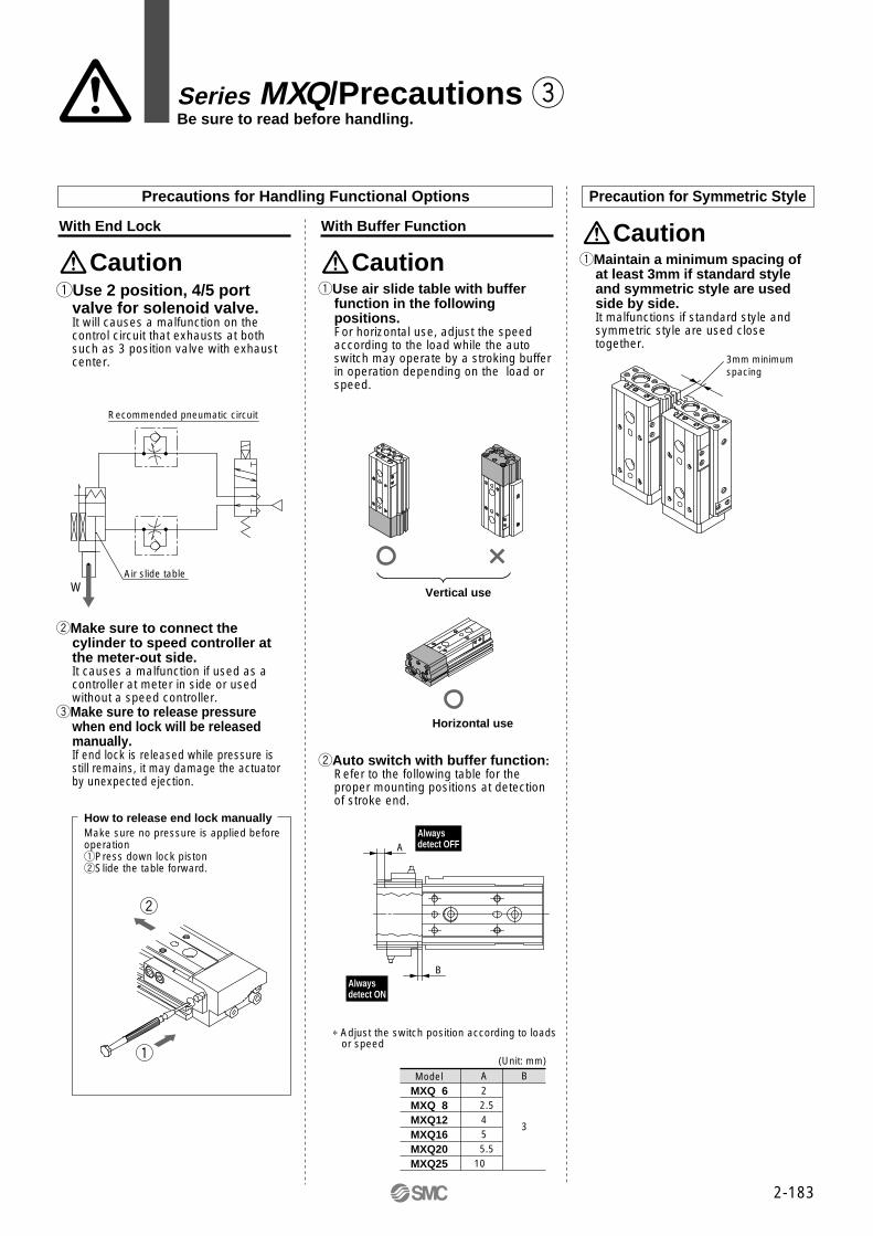
qUse 2 position, 4/5 port valve for solenoid valve.It will causes a malfunction on the control circuit that exhausts at both such as 3 position valve with exhaust center.
Caution
With End Lock
Precautions for Handling Functional Options
wMake sure to connect the cylinder to speed controller at the meter-out side.It causes a malfunction if used as a controller at meter in side or used without a speed controller.
eMake sure to release pressure when end lock will be released manually.If end lock is released while pressure is still remains, it may damage the actuator by unexpected ejection.
How to release end lock manuallyMake sure no pressure is applied beforeoperationqPress down lock pistonwSlide the table forward.
qUse air slide table with buffer function in the following positions.For horizontal use, adjust the speed according to the load while the auto switch may operate by a stroking buffer in operation depending on the load or speed.
Caution
With Buffer Function
wAuto switch with buffer function: Refer to the following table for the proper mounting positions at detection of stroke end.
∗ Adjust the switch position according to loads or speed
ModelMXQ 6MXQ 8MXQ12MXQ16MXQ20MXQ25
A2
2.545
5.510
B
3
(Unit: mm)
Vertical use
Horizontal use
Series MXQ/Precautions eBe sure to read before handling.
W
Precaution for Symmetric Style
qMaintain a minimum spacing of at least 3mm if standard style and symmetric style are used side by side.It malfunctions if standard style and symmetric style are used close together.
Caution
3mm minimumspacing
Alwaysdetect OFF
Alwaysdetect ON
A
B
w
q
Air slide table
Recommended pneumatic circuit
2-183

Series MXQ ø6, ø8, ø12, ø16, ø20, ø25
Air Slide Table
Special functionStyle Electricalentry
Grommet
Yes
Yes
Wiring(Output)
2 wire
3 wire(Equiv. to NPN)
Load voltage
100V
ACDC
Auto switch model
A90V
A93V
A96V
M9NV
M9PV
M9BV
M9NWV
M9PWV
M9BWV
Lead wire (m)∗
0.5(—)
3(L)
�
�
�
�
�
�
�
�
�
�
�
�
�
�
�
�
�
�
IC
IC
RelayPLC
RelayPLC
Applicable load
Applicable Auto Switches
∗ Lead wire length 0.5m··········· — (Example) A93 3m··········· L A93L
≤100V
12V
5V, 12V
12V
5V
24V
No
Grommet
Diagnostic indication(2 colour)
Ree
dsw
itch
So
lid s
tate
sw
itch
A90
A93
A96
M9N
M9P
M9B
M9NW
M9PW
M9BW
Electrical entry
Perpendicular In-linelndi
cato
r
24V
PLC: Programmable Logic Controller
3 wire (NPN)
3 wire (PNP)
2 wire
3 wire (NPN)
3 wire (PNP)
2 wire
How to Order
10, 20, 30, 40, 5010, 20, 30, 40, 50, 7510, 20, 30, 40, 50, 75, 10010, 20, 30, 40, 50, 75, 100, 12510, 20, 30, 40, 50, 75, 100, 125, 15010, 20, 30, 40, 50, 75, 100, 125, 150
ø6ø8
ø12ø16ø20ø25
Bore size (Stroke mm)
21n
—Sn
Number of auto switches
MXQ 12 50 M9N S
Adjuster option
Functional options
AS FR
ExtentionRetractionBoth endsExtentionRetractionBoth endsExtentionRetractionBoth ends
AS AT A BS(1)
BT(1)
B(1)
CS CT C
StandardWith bufferWith end lockAxial pipingWith buffer and end lockWith buffer and axial piping
—
—
Adjusteroptions
Functionaloptions
Combination of Options
∗ Refer to the table below for Parts No. of auto switch
Auto switch— Without auto switch
—
Note 1) Not available with absorberfor series MXQ6.
Note 2) Not available with end lock for series MXQ6.
F R(2)
P FR(2)
FP
AS, CS
AT, CT
A, C
BS
BT
B
Detail
spec.
P.5.3-19P.5.3-20
P.5.3-39
P5.3-66
L
StandardSymmetric
—L
SymmetricStyle
Without adjuster
Rubber stopper
Shock absorber
Metal stopper
— F R P FR FP
�
�
�
�
X
�
X
�
�
X
X
�
X
X
�
�
X
X
�
X
X
�
�
X
X
X
X
X
�
�
X
X
X
X
X
�
�
�
�
�
�
�
� Available X Not available
(3) (3) (3)
(3)
Note 3) About combination of buffer mechanism style and extetion stroke adjuster style, the buffer stroke is shortened by the adjusted length with extetion stroke adjuster.
E
Rc(Pt)G(PF)
—E
Filetage(ø20 à ø25)
2-184

Bore size (mm)
Piping port
Fluid used
Action
Operating pressure
Proof pressure
Ambient and fluid temperature
Specifications
Air
Double acting
0.15 to 0.7MPa
1.05MPa
–10 to 60°C
50 to 500mm/s(Adjuster option/Metal stopper: 50 to 200mm/s)
Rubber bumper (Standard, Adjuster option/Rubber stopper)Shock absorber (Adjuster option/Shock absorber)
None (Adjuster option/Metal stopper)
+1 0
Not required
Reed switch (2 wire, 3 wire)Solid state switch (2 wire, 3 wire)
2 colour indication solid state switch (2 wire, 3 wire)
mm
M5
Operating speed range
MXQ 6
MXQ 8
MXQ12
MXQ16
MXQ20
MXQ25
Standard Stroke
Standard stroke (mm)
10, 20, 30, 40, 50
10, 20, 30, 40, 50, 75
10, 20, 30, 40, 50, 75, 100
10, 20, 30, 40, 50, 75, 100, 125
10, 20, 30, 40, 50, 75, 100, 125, 150
10, 20, 30, 40, 50, 75, 100, 125, 150
Cushion
Lubrication
Auto switch
Tolerance of stroke length
6 8 12 16 20 25Rc(PT)1/8
Adjuster options
Options
Extension (AS)
Retraction (AT)
Both ends (A)
Extension (BS)
Retraction (BT)
Both ends (B)
Extension (CS)
Retraction (CT)
Both ends (C)
Rubber stopper
Shock absorber
Metal stopper
Functional options
With buffer (F)
With end lock (R)
Axial piping (P)
Stroke adjusting range 0 to 5mm
With shock absorberoption is not available for series MXQ6.
Stroke adjusting range 0 to 5mm
End lock option is not available for series MXQ6.
∗Refer to p.2-186 and 2-187 for the detailed specifications of adjustment and function options.
Model
2-185
Air Slide Table Series MXQ

Symmetric
Bore size
Adjustable range—
-X11-X12
MXQ
5mm15mm25mm
68
12162025
12 X11
Adjuster options
AS
Standard
Option
ø6ø8
ø12ø16ø20ø25
Note 1) “-X12” (adjustable range : 25mm)is not adjustable for series MXQ6.Note 2) “-X11” and “-X12” are not available with shock absorber.Note 3) Shock absorber is not available for series MXQ6.Note 4) “-X11” and “-X12” are not available as the built-in style.Note 5) Refer to p.2-216 and 2-218 for the dimdensions.
Theoretical Force
0.2
11
8
20
15
45
34
80
60
126
94
196
151
Bore size(mm)
Rod size(mm)
Piston area(mm2)
Actiondirection
Operating pressure (MPa)
6
8
12
16
3
4
6
8
OUT
IN
57
42
OUT
IN
101
75
OUT
IN
226
170
OUT
IN
402
302
0.3
17
13
30
23
68
51
121
91
188
141
295
227
0.4
23
17
40
30
90
68
161
121
251
188
393
302
0.5
29
21
51
38
113
85
201
151
314
236
491
378
0.6
34
25
61
45
136
102
241
181
377
283
589
454
0.7
40
29
71
53
158
119
281
211
440
330
687
529
Introducing dual rods, double the output of previous cylinder (Unit: N)
Note) Theoretical force (N)=Pressure (MPa) X piston area(mm2)
MXQ 6MXQ 8MXQ12MXQ16MXQ20MXQ25
Model
Standard stroke (mm)
(Unit: g)
20 10
25 12
OUT
IN
628
471
OUT
IN
982
756
INOUT
Additional weight of adjuster option
10
100
140
335
605
1100
1750
20
120
170
340
610
1100
1750
30
140
210
380
670
1100
1750
40
180
250
450
735
1200
1950
50
200
315
490
835
1400
2400
75
385
655
1000
1750
2750
100
745
1250
2350
3450
125
1400
2650
4300
150
2900
4700
6
10
25
45
80
130
5
10
23
40
65
110
25
35
70
105
130
200
40
100
160
310
560
13 + 0.2S
26 + 0.2S
43 + 0.2S
55 + 0.2S
166 + 0.5S
240 + 0.5S
Axial piping(S: stroke mm)
Withend lock
With buffer
How to Order Stroke Adjuster(Accessory Parts)
Weight
L
StandardSymmetric
—L
ExtensionRetractionExtensionRetractionExtensionRetraction
ASATBSBTCSCT
Rubberstopper
Shockabsorber
Metalstopper
Style
Rubber stopper
With shock absorber
Metal stopper
Stroke adjustable range
0 to 5mm
Refer to the dimensions on p.2-217
0 to 5mm
Stroke Adjustable Range by Adjuster Options (Both are the same for front and back ends)
∗Wide range adjusters for rubber stopper and metal stopper are available as optional specification.
Option Specifications
Additional wight of function option
Rubber stopperExtension Retraction Extension Retraction Extension Retraction
30
47
75
170
220
23
30
53
120
140
Shock absorber
10
23
35
60
115
180
5
10
23
40
65
110
Metal stopper
2-186
Series MXQ

Table Accuracy
(Unit: mm)
Model
B side parallelism to A side
B side travelling parallelism to A side
C side parallelism to A side
Dimension tolerance of M
Dimension tolerance of W
Radial clearance (µ m)
MXQ6
Refer to Table 1
Refer to Fig.1
0.05mm
±0.08mm (±0.1mm)∗1
±0.1mm
Shock Absorber Specifications
Model
Bore size (mm)
Operating speed range
Buffer stroke (mm)
Buffer strokeload (N)
MXQ6
At 0 stroke
At max.stroke
6
3
6
MXQ8
8
5
8
MXQ12
12
10
13
MXQ16
16
13
17
MXQ20
20
17
25
MXQ25
25
21
29
5 10
50 to 500mm/s (50 to 300mm/s for horizontal use)
Style Model No.
D-M9BV
D-M9NV
D-M9PV
Solid stateswitch
Specifications
2 wire with light
3 wire W/ light, Output style: NPN
3 wire W/ light, Output style: PNP
Electrical entry
Perpendicular
Model
Bore size (mm)
Operating speed range
Holding force (N)
MXQ8
8
25
MXQ12
12
60
MXQ16
16
110
MXQ20
20
160
MXQ25
25
250
50 to 500mm/s
Please order separately for auto switch with buffer mechanism from above model.
Note 1) Refer to p.2-183 for cautions when handling buffer functions.Note 2) When adjusting stroke with extension stroke end adjuster, the buffer
stroke is shortened by the adjusted lengh.
Note) Refer to p.2-183 for cautions when handling end locks.
Applicable slide table
Max. absorbing energy (J)
Absorbed stroke (mm)
Max. collision speed (mm/s)
Max. used frequency (cycle/min)
Max. thrust tolerance (N)
Ambient temperature range
RB0805
MXQ8
0.98
5
80
245
1.96
3.83
15
RB0806
MXQ12
RB1007
MXQ16
RB1411
MXQ20
RB1412
MXQ25
Spring force(N)
Weight (g)
Expanded
Compressed
2.94
6
80
245
1.96
4.22
15
5.88
7
50 to 500
70
422
–10 to 60°C
4.22
6.86
25
14.7
11
45
814
6.86
15.30
65
19.6
12
45
814
6.86
15.98
65
With buffer mechanism With end lock
With End Lock Specifications
With Buffer Mechanism Specifications
Auto Switch Applied for Buffer Section
–4 to 0
MXQ8
–4 to 0
MXQ12
–6 to 0
MXQ16
–10 to 0
MXQ20
–12 to 0
MXQ25
–14 to 0
∗1) ±0.1mm for stroke 75mm or more
MXQ 6
MXQ 8
MXQ12
MXQ16
MXQ20
MXQ25
ModelStroke (mm)
10
0.025
0.025
0.03
0.035
0.04
0.045
20
0.03
0.03
0.03
0.035
0.04
0.045
30
0.035
0.035
0.035
0.04
0.04
0.045
40
0.04
0.04
0.04
0.045
0.045
0.05
50
0.045
0.055
0.045
0.05
0.055
0.06
75
0.065
0.065
0.065
0.07
0.07
100
0.075
0.08
0.095
0.09
125
0.095
0.105
0.115
150
0.125
0.125
B side parallelism to A sideTable 1
WA
BC
M
Radialclearance
0.06
0.04
0.02
0Tra
velli
ng p
aral
lelis
m (
mm
)
50 100 150Stroke (mm)
B side travelling parallelism to A sideFig. 1
Travelling ParallelismDeflection on the dial gauge when the table isfully stroked while its body is fixed to standardbase surface.
Shock absorber model
2-187
Air Slide Table Series MXQ

MXQ16-100MXQ16-125
MXQ16-75
MXQ16-20MXQ16-30
MXQ16-10
MXQ16-40
MXQ16-50
MXQ25-100MXQ25-125MXQ25-150
MXQ25- 50MXQ25- 75
MXQ25- 10MXQ25- 20MXQ25- 30MXQ25- 40
MXQ16-30
MXQ16-50
MXQ16-20
MXQ16-10
MXQ16-40
MXQ16-75MXQ16-100MXQ16-125
MXQ16-10
MXQ16-20
MXQ16-100MXQ16-30
MXQ16-50
MXQ16-75MXQ16-40
MXQ16-125
MXQ20-10
MXQ20-50
MXQ20-125
MXQ20-20
MXQ20-75MXQ20-30
MXQ20-150
MXQ20-40
MXQ20-100
MXQ25-10
MXQ25-30MXQ25-50MXQ25-125
MXQ25-150MXQ25-100
MXQ25-75
MXQ25-20
MXQ25-40
MXQ20-125MXQ20-150
MXQ20-50
MXQ20-10
MXQ20-30
MXQ20-20
MXQ20-100
MXQ20-40MXQ20-75
MXQ25-125MXQ25-100MXQ25-75
MXQ25-150
MXQ25-50
MXQ25-20
MXQ25-40
MXQ25-30
MXQ20-100MXQ20-125MXQ20-150
MXQ20-10MXQ20-20MXQ20-30
MXQ20-50MXQ20-75
MXQ20-40
Table Deflection (for reference)
Table deflection by pitch moment Table deflection by yaw moment Table deflection by roll momentTable pitch deflection due to static pitchmoment applied at arrow for fully extendedstroke of side table
Table yaw deflection due to static yaw momentapplied at arrow for fully extended stroke of sidetable.
Table roll deflection arrow A due to static rollmoment applied at arrow F when Lr = (seetable) and table is retracted.
Load (N)
Tab
le d
efle
ctio
n (m
m)
Load (N)
Tab
le d
efle
ctio
n (m
m)
Load (N)
Tab
le d
efle
ctio
n (m
m)
Load (N)
Tab
le d
efle
ctio
n (m
m)
Load (N)
Tab
le d
efle
ctio
n (m
m)
Load (N)
Tab
le d
efle
ctio
n (m
m)
Lr=40mm
Lr=70mm
Load (N)
Tab
le d
efle
ctio
n (m
m)
Load (N)
Tab
le d
efle
ctio
n (m
m)
Load (N)
Tab
le d
efle
ctio
n (m
m)
Lr=90mm
0.03
0.02
0.01
10 20 30
20 40 60
0.03
0.02
0.01
20 40 60 80 100
0.01
0.02
0.03
0.04
0.03
0.02
0.01
10 20 30
0.04
0.02
20 40 60
0.04
0.06
20 40 60 80 100
0.10
0.02
0.04
0.06
0.08
0.015
0.010
40 80 120
0.005
0.010
40 80 120
0.005
0.012
0.008
120
0.016
0.004
0.020
16040 80
0
0
0
0
0
0
0
0
0
ø8 ø8 ø8
ø12 ø12 ø12
F A
Lr
F
MXQ6-10
MXQ6-20
MXQ6-30MXQ6-50
MXQ6-40
MXQ6-10MXQ6-10MXQ6-20MXQ6-20MXQ6-30MXQ6-30 MXQ6-50MXQ6-50
MXQ6-40MXQ6-40MXQ6-10MXQ6-20MXQ6-30 MXQ6-50
MXQ6-40
MXQ12-10
MXQ12-30
MXQ12-20
MXQ12-50
MXQ12-40
MXQ12-75
MXQ12-100
MXQ12-10
MXQ12-30
MXQ12-20
MXQ12-50
MXQ12-40
MXQ12-75
MXQ12-100
MXQ12-75MXQ12-75
MXQ12-10MXQ12-10
MXQ12-40MXQ12-40
MXQ12-20MXQ12-20
MXQ12-30MXQ12-30
MXQ12-100MXQ12-100
MXQ12-50MXQ12-50
MXQ12-75
MXQ12-10
MXQ12-40
MXQ12-20
MXQ12-30
MXQ12-100
MXQ12-50
MXQ12-100MXQ12-100MXQ12-75MXQ12-75MXQ12-50MXQ12-50MXQ12-40MXQ12-40
MXQ12-30MXQ12-30MXQ12-20MXQ12-20MXQ12-10MXQ12-10
MXQ12-100MXQ12-75MXQ12-50MXQ12-40
MXQ12-30MXQ12-20MXQ12-10
MXQ8-20MXQ8-20
MXQ8-10MXQ8-10
MXQ8-30MXQ8-30MXQ8-40MXQ8-40
MXQ8-50MXQ8-50
MXQ8-75MXQ8-75
MXQ8-20
MXQ8-10
MXQ8-30MXQ8-40
MXQ8-50
MXQ8-75MXQ8-75MXQ8-75
MXQ8-10MXQ8-10MXQ8-20MXQ8-20 MXQ8-30MXQ8-30
MXQ8-50MXQ8-50MXQ8-40MXQ8-40
MXQ8-75
MXQ8-10MXQ8-20 MXQ8-30
MXQ8-50MXQ8-40
ø6 ø6 ø60.05
MXQ8-10MXQ8-10
MXQ8-30MXQ8-30
MXQ8-75MXQ8-75
MXQ8-20MXQ8-20MXQ8-40MXQ8-40
MXQ8-50MXQ8-50
MXQ8-10
MXQ8-30
MXQ8-75
MXQ8-20MXQ8-40
MXQ8-50
MXQ6-30
MXQ6-10
MXQ6-20
MXQ6-30
MXQ6-50
MXQ6-40
MXQ6-10
MXQ6-20
MXQ6-30MXQ6-50
MXQ6-40
MXQ6-10
MXQ6-20
MXQ6-30
MXQ6-50
MXQ6-40
2-188
Series MXQ

Load (N)
Tab
le d
efle
ctio
n (m
m)
Load (N)
Tab
le d
efle
ctio
n (m
m)
Load (N)
Tab
le d
efle
ctio
n (m
m)
Load (N)
Tab
le d
efle
ctio
n (m
m)
Load (N)
Tab
le d
efle
ctio
n (m
m)
Load (N)
Tab
le d
efle
ctio
n (m
m)
Lr=120mm
Lr=160mm
Load (N)
Tab
le d
efle
ctio
n (m
m)
Load (N)
Tab
le d
efle
ctio
n (m
m)
Load (N)
Tab
le d
efle
ctio
n (m
m)
Lr=200mm
0.06
0.04
0.02
50 100 200
100 200 300
0.06
0.04
0.02
100 200 300 400 500
0.04
0.06
0.08
0.10
0.08
0.04
50 100 200
0.04
100 200 300
0.08
0.12
100 200 300 400 500
0.12
0.04
0.08
0.04
0.03
100 200 300
0.02
0.04
100 200 300
0.02
0.04
0.02
600
0.06
0.08
800200 400
0
0
0
0
0
0
0
0
0
ø16 ø16 ø16
ø20 ø20 ø20
ø25 ø25 ø25
0.12
F A
Lr
F
Table deflection by pitch moment Table deflection by yaw moment Table deflection by roll momentTable pitch deflection due to static pitchmoment applied at arrow for fully extendedstroke of side table.
Table yew deflection due to static yaw momentapplied at arrow for fully extended stroke of sidetable.
Table roll deflection arrow A due to static rollmoment applied at arrow F when Lr=(seetable)and table is retracted.
MXQ16-100MXQ16-100MXQ16-125MXQ16-125
MXQ16-75MXQ16-75
MXQ16-20MXQ16-20MXQ16-30MXQ16-30
MXQ16-10MXQ16-10
MXQ16-40MXQ16-40
MXQ16-50MXQ16-50
MXQ16-100MXQ16-125
MXQ16-75
MXQ16-20MXQ16-30
MXQ16-10
MXQ16-40
MXQ16-50
MXQ25-100MXQ25-100MXQ25-125MXQ25-125MXQ25-150MXQ25-150
MXQ25- 50MXQ25- 50MXQ25- 75MXQ25- 75
MXQ25- 10MXQ25- 10MXQ25- 20MXQ25- 20MXQ25- 30MXQ25- 30MXQ25- 40MXQ25- 40 MXQ25-100
MXQ25-125MXQ25-150
MXQ25- 50MXQ25- 75
MXQ25- 10MXQ25- 20MXQ25- 30MXQ25- 40
MXQ16-30
MXQ16-50
MXQ16-20
MXQ16-10
MXQ16-40
MXQ16-75MXQ16-100MXQ16-125
MXQ16-30
MXQ16-50
MXQ16-20
MXQ16-10
MXQ16-40
MXQ16-75MXQ16-100MXQ16-125
MXQ16-10
MXQ16-20
MXQ16-100MXQ16-30
MXQ16-50
MXQ16-75MXQ16-40
MXQ16-125
MXQ16-10
MXQ16-20
MXQ16-100MXQ16-30
MXQ16-50
MXQ16-75MXQ16-40
MXQ16-125
MXQ20-10MXQ20-10
MXQ20-50MXQ20-50
MXQ20-125MXQ20-125
MXQ20-20MXQ20-20
MXQ20-75MXQ20-75MXQ20-30MXQ20-30
MXQ20-150MXQ20-150
MXQ20-40MXQ20-40
MXQ20-100MXQ20-100
MXQ20-10
MXQ20-50
MXQ20-125
MXQ20-20
MXQ20-75MXQ20-30
MXQ20-150
MXQ20-40
MXQ20-100
MXQ25-10MXQ25-10
MXQ25-30MXQ25-30MXQ25-50MXQ25-50MXQ25-125MXQ25-125
MXQ25-150MXQ25-150MXQ25-100MXQ25-100
MXQ25-75MXQ25-75
MXQ25-20MXQ25-20
MXQ25-40MXQ25-40
MXQ25-10
MXQ25-30MXQ25-50MXQ25-125
MXQ25-150MXQ25-100
MXQ25-75
MXQ25-20
MXQ25-40
MXQ25-10
MXQ20-125MXQ20-125MXQ20-150MXQ20-150
MXQ20-50MXQ20-50
MXQ20-10MXQ20-10
MXQ20-30MXQ20-30
MXQ20-20MXQ20-20
MXQ20-100MXQ20-100
MXQ20-40MXQ20-40MXQ20-75MXQ20-75
MXQ20-125MXQ20-150
MXQ20-50
MXQ20-10
MXQ20-30
MXQ20-20
MXQ20-100
MXQ20-40MXQ20-75
150 150
0.01
400
0.06
400 500 600
0.08
MXQ25-125MXQ25-125MXQ25-100MXQ25-100MXQ25-75MXQ25-75
MXQ25-150MXQ25-150
MXQ25-50MXQ25-50
MXQ25-20MXQ25-20
MXQ25-40MXQ25-40
MXQ25-30MXQ25-30MXQ25-125MXQ25-100MXQ25-75
MXQ25-150
MXQ25-50
MXQ25-20
MXQ25-40
MXQ25-30
0.02
MXQ20-100MXQ20-100MXQ20-125MXQ20-125MXQ20-150MXQ20-150
MXQ20-10MXQ20-10MXQ20-20MXQ20-20MXQ20-30MXQ20-30
MXQ20-50MXQ20-50MXQ20-75MXQ20-75
MXQ20-40MXQ20-40 MXQ20-100MXQ20-125MXQ20-150
MXQ20-10MXQ20-20MXQ20-30
MXQ20-50MXQ20-75
MXQ20-40
MXQ6-10
MXQ6-20
MXQ6-30MXQ6-50
MXQ6-40
MXQ6-10MXQ6-20MXQ6-30 MXQ6-50
MXQ6-40
MXQ12-10
MXQ12-30
MXQ12-20
MXQ12-50
MXQ12-40
MXQ12-75
MXQ12-100
MXQ12-75
MXQ12-10
MXQ12-40
MXQ12-20
MXQ12-30
MXQ12-100
MXQ12-50
MXQ12-100MXQ12-75MXQ12-50MXQ12-40
MXQ12-30MXQ12-20MXQ12-10
MXQ8-20
MXQ8-10
MXQ8-30MXQ8-40
MXQ8-50
MXQ8-75MXQ8-75
MXQ8-10MXQ8-20 MXQ8-30
MXQ8-50MXQ8-40
MXQ8-10
MXQ8-30
MXQ8-75
MXQ8-20MXQ8-40
MXQ8-50
MXQ6-10
MXQ6-20
MXQ6-30
MXQ6-50
MXQ6-40
2-189
Air Slide Table Series MXQ

Series MXQHow to Select
Selection Procedure Formula and Data Selection Example
Operating conditions
List the operating conditions according to mounting position and work form.
Cylinder: MXQ16-50Cushion: Robber stopperMounting on work tableMounting: Horizontal well Average speed: Va=300[mm/s]Applied load: W=10[N]L1=10mmL2=30mmL3=30mm
Kinetic energy
Calculate kinetic energy E(J) of load.Calculate allowable kinetic energy Ea(J). Check that kinetic energy of load does not exceed allowable kinetic energy.
Load rate
Calculate allowable applied load Wa(N).
Calculate load rate of applied load α1.
3-1 Load rate of applied load
Calculate static moment M(Nm).Calculate allowable static momentMa(Nm).
Calculate Load rate of static moment α2.
3-2 Load rate of static moment
Calculate dynamic momentMe(Nm).
Calculate allowable dynamic moment Mea(Nm).
Calculate load rate of dynamic moment α3 .
3-3 Load rate of dynamic moment
It is possible to use when the sum of load rates does not exceed 1.
3-4 Sum of load rate
Σαn=α1+α2+·········+αn≤1
1 420 2E= 1 ( ) =0.088 2 1000 V=1.4 X 300=420
Ea=1 X 0.11=0.11
Possible to use by E=0.088≤Ea=0.11
Wa=1 X 1 X 4=4 K=1 β =1 Wmax=4α1=1/4=0.25
Examine for MyMy=1 X 9.8(10+30)/1000 =0.39 A3=30
May=1 X 1 X 18=18 Mymax=18 K=1 γ=1
α2=0.39/18=0.022
Examine for Mep (30+10.5)Mep=1/3 X 16.8 X 9.8 X =2.2 1000We=4/100 X 1 X 420=16.8A2=10.5Meap=1 X 0.7 X 18=12.6 K=1 γ=0.7 Mpmax=18α3=2.2/12.6=0.1
Examine for Mey (30+24.5)Mey=1/3 X 16.8 X 9.8 X =3.0 1000 We=168 A4=24.5Meay=12.6(Same value as Meap)α’3=3.0/12.6=0.24
Σαn=α1+α2+α’2+α3+α’3
=0.25+0.022+0.011+0.17+0.24=0.693≤1And it is possible to use.
1
2
3
· Model used · Type of cushion · Mounting position of work · Mounting direction · Average speed Va (mm/s) · Applied load W (N): Fig 1 · Overhang Ln (mm): Fig 2
Wa=K β Wmax Work mounting coefficient K: Fig 3 Allowable applied load coefficient B: Graph 1 Max. allowable applied load Wmax: Table 2α1=W/Wa
M=W X (Ln+An)/1000 Correction value for center position distance of moment An Table 3
Ma=K γ Mmax Work mounting coefficient K: Fig 3 Allowable moment coefficient γ : Graph 2 Max. allowable moment Mmax: Table 4
α2=M/Ma
(Ln+An)Me=1/3 We X 9.8 1000 Load equivalent to collision We= δ W V δ: Damper coefficient Rubber stopper without adjuster=4/100 Shock absorber=1/100 Metal stopper=16/100 Correction value for center position distance of moment An: Table 3
Mea=K γ Mmax Work mounting coefficient K: Fig 3 Allowable moment coefficient γ : Graph 2 Max. allowable moment Mmax: Table 4
α3=Me/Mea
RollYaw
Pitch
Yaw
Examine for MrMr=1 X 9.8(30+10.5)/1000 =0.39 A6=10.5
Mar=36 Mrmax=36 K=1 γ=1
α’2=0.39/36=0.011
L2+A
5
L3
L1
Ea= K E max
1 V 2E= W ( ) 2 1000
Collision Speed=1.4 Va
Work mounting coefficient K: Fig 3
Max. allowable kinetic energy Emax: Table 1Kinetic energy(E) ≤ Allowable kinetic energy(Ea)
∗ Correction coefficient
2-190

SymbolAn (n=1 to 6)EEmaxLn (n=1 to 3)M (Mp, My, Mr)Ma (Map, May, Mar)Me (Mep, Mey)Mea (Meap, Meay)Mmax (Mpmax, Mymax, Mrmax)V
DefinitionCorrection value for center position distance of momentKinetic energyAllowable kinetic energyOverhangStatic moment (Pitch, Yaw, Roll)Allowable static moment (Pitch, Yaw, Roll)Dynamic moment (Pitch, Yaw)Allowable Dynamic moment (Pitch, Yaw)Maximum allowable moment (Pitch, Yaw, Roll)Collision speed
Unitmm
JJ
mmNmNmNmNmNm
mm/s
VaWWaWeWmaxαβγK
DefinitionAverage speedApplied loadAllowable applied loadLoad equivalent to collisionMax. allowable applied loadLoad rateApplied load coefficientMoment coefficientMounting work coefficient
Unitmm/s
kgkgkgkg
Symbol
MXQ 6MXQ 8MXQ12MXQ16MXQ20MXQ25
Model10 1.42.04.7
13 19 32
Maximum Allowable Moment: Mmax(Nm)Table 4
Correction Value for Center Position Distance of Moment: An(mm)Table 3
Allowable Kinetic Energy: Emax(J)Table 1 Table 2Maximum AllowableApplied Load: Wmax(kg)
Allo
wab
le a
pplie
d lo
ad c
oeffi
cien
t β 1.0
0.7
0.5
0.4
0.3
0.2
50 100 200 300 500 700Average speed Va (mm/s)
Allowable Applied Load Coefficient: βGraph 1
Allo
wab
le m
omen
t coe
ffici
ent γ
1.0
0.7
0.5
0.4
0.3
0.2
50 100 200 300 500 700Average speed Va (mm/s) Collision speed V (mm/s)
Allowable Moment Coefficient: γGraph 2
Note) Use average speed when calculating static moment. Use collision speed when calculating kinetic moment.
Applied Load: W(kg)Fig.1 Overhang: Ln(mm), Corrected Value for Centre Distance of Moment: An(mm)Fig.2
W
W
Pitch moment Yaw moment Roll moment
Sta
tic m
omen
tD
ynam
ic m
omen
t
Note) Static moment: Moment by gravity Dynamic moment: Moment by impact of collision against stopper
MXQ 6MXQ 8MXQ12MXQ16MXQ20MXQ25
Model
1014.516.521 27 29.535.5
Corrected value for center position distance of moment (Refer to Graph 2)
MXQ 6MXQ 8MXQ12MXQ16MXQ20MXQ25
Model
0.612469
MXQ 6MXQ 8MXQ12MXQ16MXQ20MXQ25
Model
Allowable kinetic energy
Without adjusterRubber stopper
0.0180.0270.0550.11 0.16 0.24
Max. allowableapplied load
Work Mounting Coefficient: KFig.3
W
W
Table mounting
End plate mounting
K=1
K=0.6
W
Mp
L1 A1
W
Mp
L1 A2
Mep
A2
L3
Mey
L2A
4
W
My
L2 A3
W
My
L2 A4
W
Mr
L3 A5
W
Mr
L3 A6
0.0180.0270.0550.11 0.16 0.24
Shock absorber
0.0540.11 0.22 0.32 0.48
Metal stopper0.0090.0130.0270.0550.0800.12
Adjuster options
A1, A3Stroke (mm) A2 A4 A5 A6
2014.516.521 27 29.535.5
3014.518.521 27 29.535.5
4018.520.525 27 29.535.5
5018.528 25 30 33.543
75
28.534 33 37.543
100
34 42.553.550
125
42.555 64
150
56.564
6 7 9
10.514 16.5
13.516 19.524.530 37
13.516 19.524.530 37
6 7 9
10.514 16.5
Stroke (mm)20 1.42.04.7
13 19 32
30 1.42.84.7
13 19 32
40 2.83.77.2
13 19 32
50 2.87.97.2
18 27 52
75
7.915 23 36 52
100
15428478
125
42 84 140
150
84 140
10 3.55.1
11 31 47 81
20 3.55.1
11 31 47 81
30 3.56.0
11 31 47 81
40 5.16.9
13 31 47 81
50 5.17.4
13 36 57
110
75
7.414 41 66
110
100
14 41 75130
125
41 75130
150
75130
Pitch/Yaw moment: Mpmax/MymaxStroke (mm)
Roll moment: Mrmax
Note) No differences of corrected value according to stroke for A2, A4, A5 and A6
Caution Max. operating speed for metal stopper is 200mm/s.
W
Symbol
2-191
Air Slide Table Series MXQ

2-192
Dimensions MXQ 6
Model F2225212627
N44666
G 613
1121
H2326
2828
NN22333
I 999
169
J1727374865
K21.531.541.551.561.5
Z41.551.561.579.589.5
M4252628090
ZZ4858688696
MXQ6-10MXQ6-20MXQ6-30MXQ6-40MXQ6-50
Basic style
4-M2.5 Thread depth 3.5
Extension adjuster
Retraction adjuster
ø3 Depth 2.5+0.03 0
2N -1 X F
3
D
epth
2.5
+0.
03 0
(mm)
GA1313293949
HA1626202828
Refer to adjuster options for dimensions of the stroke adjuster.Rubber stopper: p.2-216Metal stopper: p.2-218
6 (W
ith e
xten
sion
adj
uste
r)
3-M3 Thread depth 5
19.5 (With extension adjuster)
10
13.5
20
4
9
4
N-M3 Thread depth 4
14 271.
5
31
5.5 3
1512
F
11
Across AA Across BB
10.5 5.5
131620
Bottom View of MXQ6-30
10.5 5.5
ø6.
5
ø7ø3.
2
ø3.
2
ø6.
5
ø7
NN-M4 Thread depth 8
0.5
4-M2.5 Thread depth 2.5
Z
ZZ
Max. 10 (With retraction adjuster)6IJ3
2 65.
53.
5
2-M2.5 Thread depth 3
Operating port 2-M5
5.5
18.2
0.3
5 M
12.5K
6.53
3.5
20
ø3H9 Depth 2.5+0.025 0
3H9
Dep
th 2
.5+
0.02
5 0
1
(NN-1) X H G
B
H
A
4
HA GA
BA
12
Series MXQ

2-193
∗ Dimensions not indicated are the same as basic style.
∗ Dimensions not indicated are the same as basic style.
With buffer (ø6) MXQ6-��F
3-M3 Thread depth 5
266.
3
Operating port 2-M5
Axial piping (ø6) MXQ6-��P
8
428
22
0.3
19.2
1630
8
5.5
12
12
12.5
Air Slide Table Series MXQ

Dimensions MXQ 6L/Symmetric Style
Model F2225212627
N44666
G 613
1121
H2326
2828
NN22333
I 999
169
J1727374865
K21.531.541.551.561.5
Z41.551.561.579.589.5
M4252628090
ZZ4858688696
MXQ6L-10MXQ6L-20MXQ6L-30MXQ6L-40MXQ6L-50
Basic style
(mm)
GA1313293949
HA1626202828
Refer to adjuster options for dimensions of the stroke adjuster.Rubber stopper: p.2-216Metal stopper: p.2-218
4-M2.5 Thread depth 2.56.5
Z
ZZ
18.2
0.3
5 M
12.5K
3 3.5
20Across AA Across BB
131620
Bottom View of MXQ6L-30
10.5 5.5
ø3.
2
ø6.
5 ø7
10.5 5.5
ø3.
2
ø6.
5 ø7
NN-M4 Thread depth 8
4-M2.5 Thread depth 3.5
Extension adjuster
Retraction adjuster
ø3 Depth 2.5+0.03 0
3
D
epth
2.5
+0.
03 0
6 (W
ith e
xten
sion
adj
uste
r)
19.5 (With extension adjuster)
3-M3 Thread depth 5
1013.5
20
4
9
4
N-M3 Thread depth 4
14 271.
5
31
5.5 3
1512
F
2N -1 X F
11
0.5
Max. 10(With extension adjuster)
6IJ3
2 6
5.5
3.5
2-M2.5 Thread depth 3Operating port 2-M5
5.5
ø3H9 Depth 2.5+0.025 0
3H9
Dep
th 2
.5+
0.02
5 0
1
(NN-1) X H G
B
H
A
4
HA GA
BA
12
2-194
Series MXQ

3-M3 Thread depth 5
Operating port 2-M5
8
4
0.3
19.2
∗ Dimensions not indicated are the same as basic style.
∗ Dimensions not indcated are the same as basic style.
With buffer (ø6) MXQ6L-��F
Axial piping (ø6) MXQ6L-��P
266.
3
5.5
12
28
22
12
12.5
1630
8
2-195
Air Slide Table Series MXQ
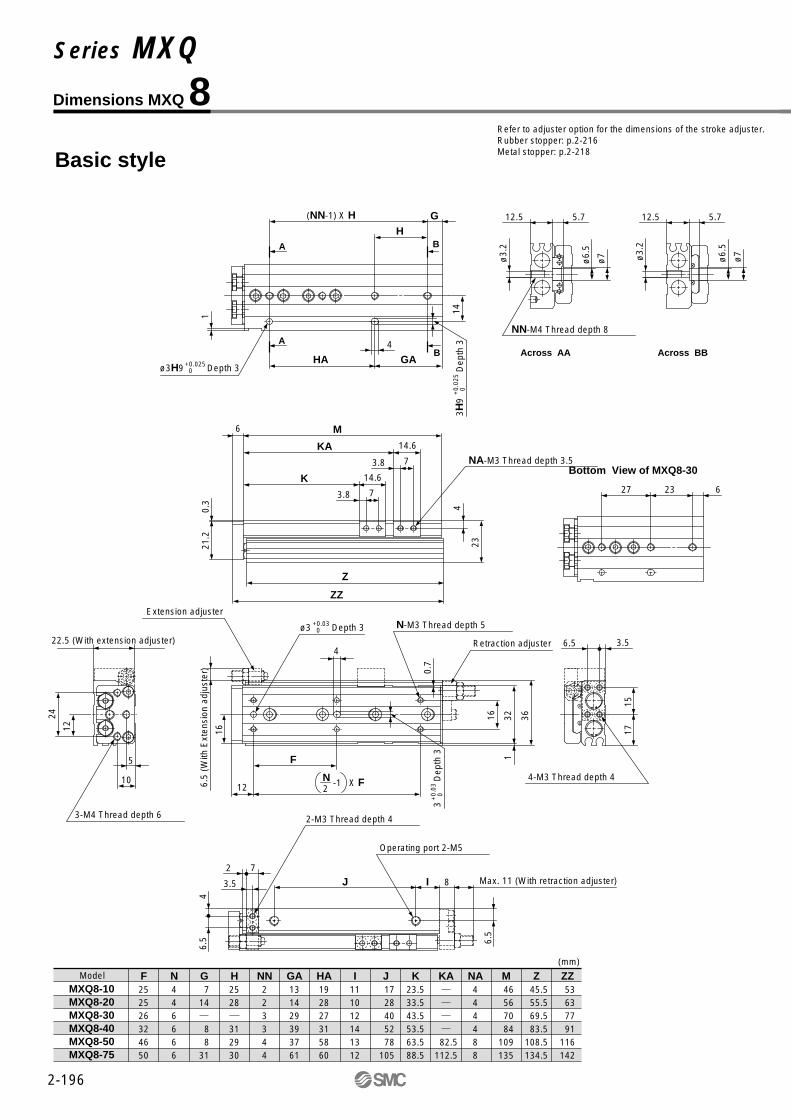
2-196
Dimensions MXQ 8
Model F252526324650
N446666
G 714
8 831
H2528
312930
NN223344
I111012141312
J 1728405278
105
K23.533.543.553.563.588.5
Z 45.5 55.5 69.5 83.5108.5134.5
M 46 56 70 84109135
ZZ 53 63 77 91116142
MXQ8-10MXQ8-20MXQ8-30MXQ8-40MXQ8-50MXQ8-75
Basic style
(mm)
GA131429393761
HA192827315860
NA444488
Refer to adjuster option for the dimensions of the stroke adjuster.Rubber stopper: p.2-216Metal stopper: p.2-218
KA
82.5112.5
4-M3 Thread depth 4
Extension adjuster
Retraction adjuster
ø3 Depth 3+0.03 0
2N -1 X F6.
5 (W
ith E
xten
sion
adj
uste
r)
3-M4 Thread depth 6
22.5 (With extension adjuster)
1612
24
5
10
4
N-M3 Thread depth 5
16 321
36
6.5 3.5
1715
F
12
3
D
epth
3+
0.03
0
0.7
Max. 11 (With retraction adjuster)8IJ3.5
2 7
6.5
4
2-M3 Thread depth 4
Operating port 2-M5
6.5
ø3H9 Depth 3+0.025 0
1(NN-1) X H G
BH
A
4
HA GAB
A
143H
9
Dep
th 3
+0.
025
0NA-M3 Thread depth 3.5
Z
ZZ
21.2
0.3
6 M
14.6K73.8
14.6KA73.8
4
23
Across AA Across BB
12.5 5.7
ø6.
5
ø7ø3.
2
12.5 5.7
ø6.
5
ø7ø3.
2
NN-M4 Thread depth 8
62327
Bottom View of MXQ8-30
Series MXQ

2-197
Extension End20
Retraction End20
Adjustable Range of Stroke(Unit: mm)
∗ Dimensions not indicated are the same as basic style.
Dimensions not indicated are the same as basic style.
With shock absorber (ø8) MXQ8-��BS, BT, B
With buffer (ø8) MXQ8-��F
∗ Dimensions not indicated are the same as basic style.
With end lock (ø8) MXQ8-��R
∗ Dimensions not indicated are the same as basic style.
Axial piping (ø8) MXQ8-��P
3-M4 Thread depth 6
Extension end shock absorber
Retraction end shock absorber
316.
3
40.5
3
Operating port 2-M5
10
528.5
25
Max. 23
Max. 328
25
2 2
22.5
0.3
22.2
11.5
1
2434
12
6.5
15
12
16
14.5
Operating port 2-M54
17.5
Air Slide Table Series MXQ

2-198
Dimensions MXQ 8L/Symmetric Style
Model F252526324650
N446666
G 714
8 831
H2528
312930
NN223344
I111012141312
J 1728405278
105
K23.533.543.553.563.588.5
Z 45.5 55.5 69.5 83.5108.5134.5
M 46 56 70 84109135
ZZ 53 63 77 91116142
MXQ8L-10MXQ8L-20MXQ8L-30MXQ8L-40MXQ8L-50MXQ8L-75
Basic style
(mm)
GA131429393761
HA192827315860
NA444488
Refer to adjuster option for the dimensions of the stroke adjuster.Rubber stopper: P.2-216Metal stopper: P.2-218
KA
82.5112.5
4-M3 Thread depth 4
Extension adjuster
Retraction adjuster
ø3 Depth 3+0.03 0
3
D
epth
3+
0.03
0
6.5
(With
ext
ensi
on a
djus
ter)
22.5 (With extension adjuster)
3-M4 Thread depth 61216
24
5
10
4
N-M3 Thread depth 5
16 321
36
6.5 3.5
1715
F
2N -1 X F
12
0.7
NA-M3 Thread depth 3.5
ZZZ
21.2
0.3
6 M
14.6KA
14.6K
3.8 7
3.8 7
4
23
ø3H9 Depth 3+0.025 0
1
(NN-1) X H G
BHA
4
HA GA
BA
143H
9
D
epth
3+
0.02
5 0
Max. 11(With extension adjuster)
8IJ3.5
2 7
6.5
4
2-M3 Thread depth 4 Operating port 2-M5
6.5
Across AA Across BB
12.5 5.7
ø3.
2
ø6.
5 ø7
12.5 5.7
ø3.
2
ø6.
5 ø7
NN-M4 Thread depth 8
62327
Bottom View of MXQ8L-30
Series MXQ

2-199
3-M4 Thread depth 6
Extension end shock absorber
Retraction end shock absorber
6.3
31
Operating port 2-M5
Operating port 2-M5
10
528.5
25
Max. 23
Max. 328
25
2 2
11.5
12434
12
6.5
15
12
14.5
4
17.5
∗ Dimensions not indicated are the same as basic style.
∗ Dimensions not indicated are the same as basic style.
With shock absorber (ø8) MXQ8L-��BS, BT, B
With buffer (ø8) MXQ8L-��F
Dimensions not indicated are the same as basic style.
With end lock (ø8) MXQ8L-��R
∗ Dimensions not indicated are the same as basic style.
Axial piping (ø8) MXQ8L-��P
Extension End20
Retraction End20
Adjustable Range of Stroke(Unit: mm)
22.5
0.3
22.2
40.5
316
Air Slide Table Series MXQ

2-200
Max. 13 (With extension stroke adjuster)10IJ4.75
2 9.5
85
2-M4 Thread depth 6 Operating port 2-M5
8.5
Dimensions MXQ 12
Model F28283834343636
N 4 4 4 6 6 810
G181820
92312
H323240
393636
NN2223345
I12121415131717
J 3434425870
110135
K 26.5 36.5 46.5 56.5 66.5 91.5116.5
Z 66 66 76 93103147172
M 67 67 77 94104148173
ZZ 76 76 86103113157182
MXQ12- 10MXQ12- 20MXQ12- 30MXQ12- 40MXQ12- 50MXQ12- 75MXQ12-100
Basic style
(mm)
GA18182038485984
HA32324039397272
NA4444488
Refer to adjuster option for the dimensions of the stroke adjuster.Rubber stopper: P.2-216Metal stopper: P.2-218
KA
117.5142.5
4-M4 Thread depth 6
Extension adjuster
Retraction adjusterø4H9 Depth 4+0.030
0
10 (
With
ext
ensi
on a
djus
ter)
3-M5 Thread depth 8
29.5 (With extension adjuster)
14.5
19.5
29
5
13
5
N-M4 Thread depth 5
20 392.
5
468 4.5
2220
F
2N -1 X F16
4HD
epth
4+
0.03
0 0
1
92939
Bottom View of MXQ12-40
Across AA Across BB
16 8
ø8.
5
ø9ø4.
2
16 8
ø8.
5
ø9ø4.
2
NN-M5 Thread depth 10
NA-M4 Thread depth 4
ZZZ
27.2
0.3
8 M
18.5K8.55
18.5KA8.55
4.8
30
ø4H9 Depth 4+0.030 0
1
(NN-1) X H G
BH
A
5
HA GA
BA
194H
9D
epth
4+
0.03
0 0
Series MXQ
2-201
3-M5 Thread depth 8
Extension end shock absorber Retraction end shock absorber
416.
3
513
Operating port 2-M5
13
537
29.5Max. 18
Max. 3010
29.5
29
0.3
29.2
10
2943
14.5
8.5
20
13
22
16.5
∗ Dimensions not indicated are the same as basic style.
∗ Dimensions not indicated are the same as basic style.
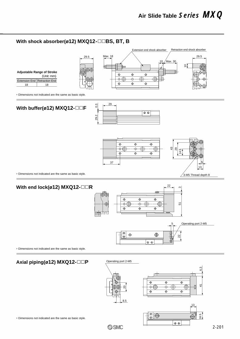
With shock absorber(ø12) MXQ12-��BS, BT, B
With buffer(ø12) MXQ12-��F
∗ Dimensions not indicated are the same as basic style.
With end lock(ø12) MXQ12-��R
∗ Dimensions not indicated are the same as basic style.
Axial piping(ø12) MXQ12-��P
Extension End18
Retraction End18
Adjustable Range of Stroke(Unit: mm)
Operating port 2-M55
22
Air Slide Table Series MXQ

2-202
4-M4 Thread depth 6
Extension adjuster
Retraction adjuster
ø4H9 Depth 4+0.030 0
4HD
epth
4+0
.030
0
10 (
With
ext
ensi
on a
djus
ter)
29.5 (With extension adjuster)
3-M5 Thread depth 8
14.5
19.5
295
13
5N-M4 Thread depth 5
20 392.
5
46
8 4.5
2220
F2N -1 X F
16
Dimensions MXQ 12L/Symmetric Style
Model F28283834343636
N 4 4 4 6 6 810
G181820
92312
H323240
393636
NN2223345
I12121415131717
J 3434425870
110135
K 26.5 36.5 46.5 56.5 66.5 91.5116.5
Z 66 66 76 93103147172
M 67 67 77 94104148173
ZZ 76 76 86103113157182
MXQ12L- 10MXQ12L- 20MXQ12L- 30MXQ12L- 40MXQ12L- 50MXQ12L- 75MXQ12L-100
Basic style
(mm)
GA18182038485984
HA32324039397272
NA4444488
Refer to adjuster option for the dimension of stroke adjuster. Rubber stopper: P.2-216Metal stopper:P.2-218
KA
117.5142.5
1
NA-M4 Thread depth 4
Z
ZZ
27.2
0.3
8 M
18.5KA
18.5K
5 8.5
5 8.5
4.8 30
92939
Bottom View of MXQ12L-40
Across AA Across BB
16 8
ø4.
2
ø8.
5 ø9
16 8
ø4.
2
ø8.
5 ø9
NN-M5 Thread depth 10
Max.13 (With retraction adjuster)
10IJ4.75
2 9.5
85
2-M4 Thread depth 6Operating port 2-M5
8.5
ø4H9 Depth 4+0.030 0
1
(NN-1) X H G
BH
A
5
HA GA
BA
194H
9D
epth
4+
0.03
0 0
Series MXQ

2-203
3-M5 Thread depth 8
Extension end shock absorberRetraction end shock absorber
6.3
41
Operating port 2-M5
13
537
29.5Max. 18
Max. 3010
29.5
10
2943
14.5
13
16.5
5
22
∗ Dimensions not indicated are the same as basic style.
∗ Dimensions not indicated are the same as basic style.
With shock absorber(ø12) MXQ12L-��BS, BT, B
With buffer(ø12) MXQ12L-��F
∗ Dimensions not indicated are the same as basic style.
With end lock(ø12) MXQ12L-��R
∗ Dimensions not indicated are the same as basic style.
Axial piping(ø12) MXQ12L-��P
Extension End18
Retraction End18
Adjustable Range of Stroke(Unit: mm)
29
0.3
29.2
51322
Operating port 2-M5
8.5
20
Air Slide Table Series MXQ

2-204
4-M5 Thread depth 7
Extension stroke adjuster
Retraction adjusterø5H9 Depth 5+0.030
0
12.5
(W
ith e
xten
sion
adj
uste
r)
3-M6 Thread depth 10
36.5 (With extension adjuster)14
.5
24.5
29
6.5
14
6
N-M5 Thread depth 6
24 493.
5
58
11 5.5
2824
.5
F
2N -1 X F21
5H9
Dep
th 5
+0.
030
0
Dimensions MXQ 16
Model F3838485840464444
N 4 4 4 4 6 6 810
G18181919
213617
H39394858
524444
NN22223345
I1212121220151823
J 40
40 50 60 68105145165
K 28 38 48 58 68 93118143
Z 77 77 87 97113145188213
M 78 78 88 98114146189214
ZZ 89 89 99109125157200225
MXQ16- 10MXQ16- 20MXQ16- 30MXQ16- 40MXQ16- 50MXQ16- 75MXQ16-100MXQ16-125
Basic style
(mm)
GA 18 18 19 19 48 73 80105
HA3939485845528888
NA44448888
Refer to adjuster option for the dimension of stroke adjuster. Rubber stopper: P.2-216Metal stopper: P.2-218
KA
91123166191
1
Max.12 (With retraction adjuster)12IJ5.5
3 11
115.
5
2-M5 Thread depth 8
Operating port 2-M5
11
Across AA Across BB
21 9
ø9.
5
ø10
.5
ø5.
1
21 9
ø9.
5
ø10
.5
ø5.
1
NN-M6 Thread depth 12
133545
Bottom View of MXQ16-50
ø5H9 Depth 5+0.030 0
1
(NN-1) X H G
BH
A
6
HA GA
BA
245H
9D
epth
5+
0.03
0 0
NA-M5 Thread depth 6.5
ZZZ
33.7
0.3
10 M
21K105.5
21KA105.5
5.5
37
Series MXQ

2-205
3-M6 Thread depth 10
Extension end shock absorber
Retraction end shock absorber
526.
3
65.5
15.5
6.541
36.5Max. 20
Max. 3412
36.5
12.5
4254
21
14
25
21
∗ Dimensions not indicated are the same as basic style.
∗ Dimensions not indicated are the same as basic style.
With shock absorber(ø16) MXQ16-��BS, BT, B
With buffer(ø16) MXQ16-��F
∗ Dimensions not indicated are the same as basic style.
With end lock(ø16) MXQ16-��R
∗ Dimensions not indicated are the same as basic style.
Axial piping(ø16) MXQ16-��P
Extension End22
Retraction End22
Adjustable Range of Stroke(Unit: mm)
30
0.3
35.7
Operating port 2-M56
29
Operating port 2-M5
11
26
Air Slide Table Series MXQ

2-206
4-M5 Thread depth 7
Extension adjuster
Retraction adjuster
ø5H9 Depth 5+0.030 0
12.5
(W
ith e
xten
sion
adj
uste
r)
36.5 (With extension adjuster)
3-M6 Thread depth 10
14.5
24.5
29
6.5
14
6
N-M5 Thread depth 6
24 493.
5
58
11 5.5
2824
.5
2N -1 X F
21
5H9
Dep
th 5
+0.0
30 0
Dimensions MXQ 16L/Symmetric Style
Model F3838485840464444
N 4 4 4 4 6 6 810
G18181919
213617
H39394858
524444
NN22223345
I1212121220151823
J 40
40 50 60 68105145165
K 28 38 48 58 68 93118143
Z 77 77 87 97113145188213
M 78 78 88 98114146189214
ZZ 89 89 99109125157200225
MXQ16L- 10MXQ16L- 20MXQ16L- 30MXQ16L- 40MXQ16L- 50MXQ16L- 75MXQ16L-100MXQ16L-125
Basic style
(mm)
GA 18 18 19 19 48 73 80105
HA3939485845528888
NA44448888
Refer to adjuster option for the dimension of stroke adjuster. Rubber stopper: P.2-216Metal stopper: P.2-218
KA
91123166191
F
1
NA-M5 Thread depth 6.5
ZZZ
33.7
0.3
10 M
21KA
21K
5.5 10
5.5 10
5.5 37
133545
Bottom View of MXQ16L-50
Across AA Across BB
21 9
ø5.
1
ø9.
5
ø10
.5
21 9
ø5.
1
ø9.
5
ø10
.5
NN-M6 Thread depth 12
Max.12 (With retraction adjuster)
12IJ5.5
3 11
115.
5
2-M5 Thread depth 8 Operating port 2-M5
11
ø5H9 Depth 5+0.030 0
1
(NN-1) X H G
BHA
6
HA GA
BA
24
5H9
Dep
th 5
+0.
030
0
Series MXQ
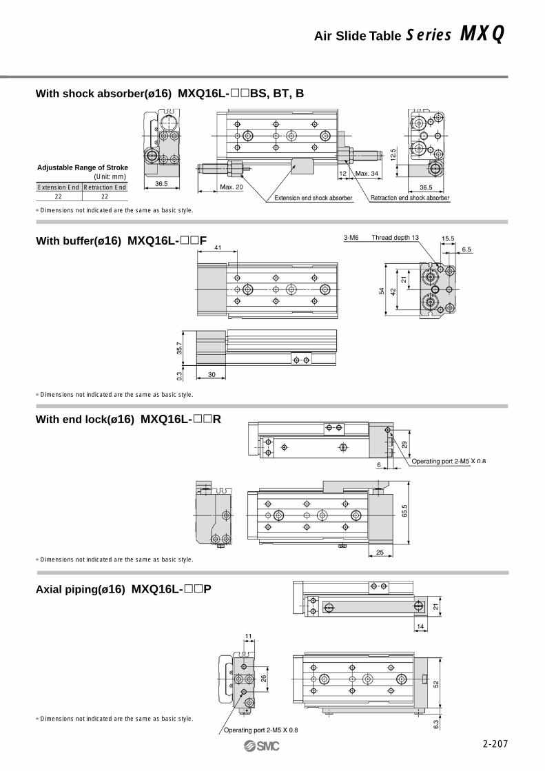
∗ Dimensions not indicated are the same as basic style.
∗ Dimensions not indicated are the same as basic style.
With shock absorber(ø16) MXQ16L-��BS, BT, B
With buffer(ø16) MXQ16L-��F
∗ Dimensions not indicated are the same as basic style.
With end lock(ø16) MXQ16L-��R
∗ Dimensions not indicated are the same as basic style.
Axial piping(ø16) MXQ16L-��P
Extension End22
Retraction End22
Adjustable Range of Stroke(Unit: mm)
2-207
Air Slide Table Series MXQ

4-M5 Thread depth 8
Extension adjuster
Retraction adjuster
ø5H9 Depth 5+0.030 0
14.5
(W
ith e
xten
sion
adj
uste
r)
3-M6 Thread depth 13
45.5 (With extension adjuster)17
.5
30
35
7
18
6
N-M5 Thread depth 8
301.
5
603
70
15 6
3331
F
2N -1 X F27
5HD
epth
5+
0.03
0 0
Dimensions MXQ 20
Model F454048584255505562
N444466888
G22222222
17183756
H46464656
56565962
NN222233444
I161616161823251821
J 46
46 46 56 72100155190215
K 31 41 51 61 71 96121146171
Z 92.5 92.5 92.5102.5120.5153.5210.5238.5266.5
M 94 94 94104122155212240268
ZZ108108108118136169226254282
MXQ20- 10MXQ20- 20MXQ20- 30MXQ20- 40MXQ20- 50MXQ20- 75MXQ20-100MXQ20-125MXQ20-150
Basic style
(mm)
GA 18 18 18 22 48 73 74 96118
HA 50 50 50 56 48 56112118124
NA444448888
Refer to adjuster option for the dimension of stroke adjuster. Rubber stopper: P.2-216Metal stopper: P.2-218
KA
126183211239
Max.14 (With retraction adjuster)13IJ6.5
2.5 13
13.5
6.5
2-M6 Thread depth 7 Operating port 2-Rc(PT)1/8
14
ø5H9 Depth 5+0.030 0
1.5
(NN-1) X H G
BH
A
6
HA GA
BA
29
5H9
Dep
th 5
+0.
030
0
NA-M6 Thread depth 6
ZZZ
41.5
0.5
13 M
25K126.5
25KA126.5
6.5
46
Across AA Across BB
26 10.5
ø9.
5
ø11ø5.
1
26 10.5
ø9.
5
ø11ø5.
1
NN-M6 Thread depth 12
123648
Bottom View of MXQ20-50
2-208
Series MXQ

2-209
3-M6 Thread depth 12
Extension end shock absorber
Retraction end shock absorber
6511
.5
78.5
Operating port 2-Rc(PT)1/8
Operating port 2-Rc(PT)1/8
18
744.5
46.50.50.5 Max. 35
Max. 5413
46.5
30.5
0.5
42.5
163560
17.5
20
33
26
14
32
8
34
∗ Dimensions not indicated are the same as basic style.
∗ Dimensions not indicated are the same as basic style.
With shock absorber(ø20) MXQ20-��BS, BT, B
With buffer(ø20) MXQ20-��F
∗ Dimensions not indicated are the same as basic style.
With end lock(ø20) MXQ20-��R
∗ Dimensions not indicated are the same as basic style.
Axial piping(ø20) MXQ20-��P
Extension End35
Retraction End35
Adjustable Range of Stroke(Unit: mm)
Air Slide Table Series MXQ

2-210
Dimensions MXQ 20L/Symmetric Style
Model F454048584255505562
N444466888
G22222222
17183756
H46464656
56565962
NN222233444
I161616161823251821
J 46
46 46 56 72100155190215
K 31 41 51 61 71 96121146171
Z 92.5 92.5 92.5102.5120.5153.5210.5238.5266.5
M 94 94 94104122155212240268
ZZ108108108118136169226254282
MXQ20L- 10MXQ20L- 20MXQ20L- 30MXQ20L- 40MXQ20L- 50MXQ20L- 75MXQ20L-100MXQ20L-125MXQ20L-150
Basic style
(mm)
GA 18 18 18 22 48 73 74 96118
HA 50 50 50 56 48 56112118124
NA444448888
Refer to adjuster option for the dimension of stroke adjuster. Rubber stopper: P.2-216Metal stopper: P.2-218
KA
126183211239
4-M5 Thread depth 8
Extension adjuster
Retraction adjuster
ø5H9 Depth 5+0.030 0
14.5
(W
ith e
xten
sion
adj
uste
r)
45.5 (With extension adjuster)
3-M6 Thread depth 13
17.5
35
30
7
18
6
N-M5 Thread depth 8
301.
5
603
70
15 6
3331
F2N -1 X F
27
5H9
Dep
th 5
+0.0
30 0
NA-M6 Thread depth 6
Z
ZZ
41.5
0.5
13 M
25KA
25K
6.5 12
6.5 12
6.5 46
Across AA Across BB
26 10.5
ø5.
1
ø9.
5
ø11
26 10.5
ø5.
1
ø9.
5
ø11
NN-M6 Thread depth 12
123648
Bottom View of MXQ20L-50
ø5H9 Depth 5+0.030 0 5H
9D
epth
5+
0.03
0 0
1.5
(NN-1) X H G
BHA
6
HA GA
BA
29
Max.14 (With retraction adjuster)
13IJ6.5
2.5 13
13.5
6.5
2-M6 Thread depth 7
Operating port 2-Rc(PT)1/814
Series MXQ

2-211
∗ Dimensions not indicated are the same as basic style.
∗ Dimensions not indicated are the same as basic style.
With shock absorber(ø20) MXQ20L-��BS, BT, B
With buffer(ø20) MXQ20L-��F
∗ Dimensions not indicated are the same as basic style.
With end lock(ø20) MXQ20L-��R
∗ Dimensions not indicated are the same as basic style.
Axial piping(ø20) MXQ20L-��P
Extension End35
Retraction End35
Adjustable Range of Stroke(Unit: mm)
Air Slide Table Series MXQ
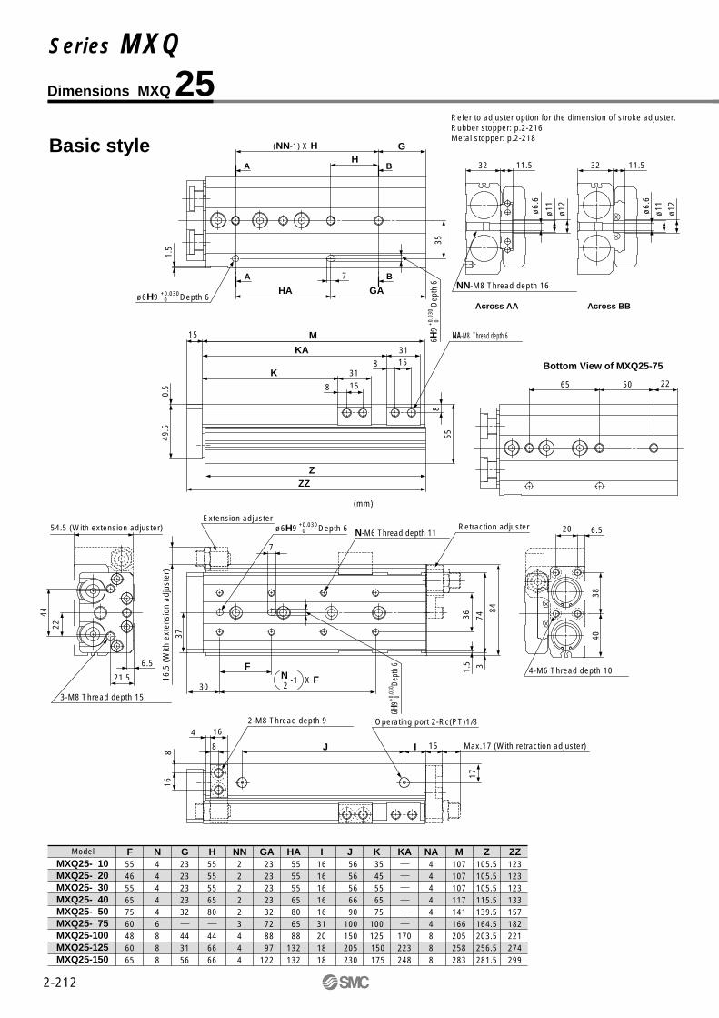
Dimensions MXQ 25
Model F554655657560486065
N444446888
G2323232332
443156
H5555556580
446666
NN222223444
I161616161631201818
J 56
56 56 66 90100150205230
K 35 45 55 65 75100125 150 175
Z105.5105.5105.5115.5139.5164.5203.5256.5281.5
M107107107117141166205258283
ZZ123123123133157182221274299
MXQ25- 10MXQ25- 20MXQ25- 30MXQ25- 40MXQ25- 50MXQ25- 75MXQ25-100MXQ25-125MXQ25-150
Basic style
GA 23 23 23 23 32 72 88 97122
HA 55 55 55 65 80 65 88132132
NA444444888
Refer to adjuster option for the dimension of stroke adjuster. Rubber stopper: p.2-216Metal stopper: p.2-218
KA
170223248
4-M6 Thread depth 10
Extension adjusterRetraction adjusterø6H9 Depth 6+0.030
0
16.5
(W
ith e
xten
sion
adj
uste
r)
3-M8 Thread depth 15
54.5 (With extension adjuster)
22
37
44
6.5
21.5
7
N-M6 Thread depth 11
361.
5
743
84
20 6.5
4038
F
2N -1 X F
30
6H9
Dept
h 6
+0.0
30 0
Max.17 (With retraction adjuster)15IJ8
4 16
168
2-M8 Thread depth 9 Operating port 2-Rc(PT)1/8
17Z
ZZ
49.5
0.5
855
(mm)
NA-M8 Thread depth 615 M
31K158
31KA158
6H9
Dep
th 6
+0.0
30 0
ø6H9 Depth 6+0.030 0
1.5
35
(NN-1) X H G
BH
A
7
HA GA
BA
225065
Bottom View of MXQ25-75
Across AA Across BB
32 11.5
ø11
ø12ø6.
6
32 11.5
ø11
ø12
NN-M8 Thread depth 16
ø6.
6
2-212
Series MXQ

2-213
3-M8 Thread depth 15
Extension end shock absorber
Retraction end shock absorber
7911
.594
Operating port 2-Rc(PT)1/8
21.5
6.550
35
54.5Max. 29
Max. 5215
54.5
0.5
49.5
16.5
4474
22
20
37
32
17
40
∗ Dimensions not indicated are the same as basic style.
∗ Dimensions not indicated are the same as basic style.
With shock absorber(ø25) MXQ25-��BS, BT, B
With buffer(ø25) MXQ25-��F
∗ Dimensions not indicated are the same as basic style.
With end lock(ø25) MXQ25-��R
∗ Dimensions not indicated are the same as basic style.
Axial piping(ø25) MXQ25-��P
Extension End35
Retraction End35
Adjustable Range of Stroke(Unit: mm)
Operating port 2-Rc(PT)1/88
40
Air Slide Table Series MXQ

2-214
Dimensions MXQ 25L/Symmetric Style
Model F554655657560486065
N444446888
G2323232332
443156
H5555556580
446666
NN222223444
I161616161631201818
J 56
56 56 66 90100150205230
K 35 45 55 65 75100125 150 175
Z105.5105.5105.5115.5139.5164.5203.5256.5281.5
M107107107117141166205258283
ZZ123123123133157182221274299
MXQ25L- 10MXQ25L- 20MXQ25L- 30MXQ25L- 40MXQ25L- 50MXQ25L- 75MXQ25L-100MXQ25L-125MXQ25L-150
Basic style
GA 23 23 23 23 32 72 88 97122
HA 55 55 55 65 80 65 88132132
NA444444888
Refer to adjuster option for the dimension of stroke adjuster. Rubber stopper: p.2-216Metal stopper: p.2-218
KA
170223248
4-M6 Thread depth 10
Extension adjuster
Retraction adjuster
16.5
(With
ext
ensio
n ad
just
er)
54.5 (With extension adjuster)
7
3-M8 Thread depth 15
22
37
446.5
21.5
N-M6 Thread depth 11
361.
5
743
84
20 6.5
4038
F
2N -1 X F
30
6H9
Dept
h 6
+0.0
30 0
ø6H9 Depth 6+0.030 0
NA-M8 Thread depth 8
Z
ZZ
49.5
0.5
15 M
31KA
31K
8 15
8 15
8
55Max.17 (With retraction adjuster)
15IJ8
4 16
168
2-M8 Thread depth 9
Operating port 2-Rc(PT)1/8
17
(mm)
ø6H9 Depth 6+0.030 0
1.5
(NN-1) X H G
BHA
7
HA GA
BA
356H
9D
epth
6+
0.03
0 0
225065
Bottom View of MXQ25L-75
Across AA Across BB
32 11.5
ø11 ø12
32 11.5
ø11 ø12
NN-M8 Thread depth 16
ø6.
6
ø6.
6
Series MXQ

2-215
4474
22
Max. 5215
54.5
3-M8 Thread depth 15
Extension end shock absorber
Retraction end shock absorber
11.5
79
94
Operating port 2-Rc(PT)1/8
Operating port 2-Rc(PT)1/8
21.5
6.550
54.5Max. 29
350.5
49.5
16.5
17
40
20
32
8
37
40
∗ Dimensions not indicated are the same as basic style.
∗ Dimensions not indicated are the same as basic style.
With shock absorber(ø25) MXQ25L-��BS, BT, B
With buffer(ø25) MXQ25L-��F
∗ Dimensions not indicated are the same as basic style.
With end lock(ø25) MXQ25L-��R
∗ Dimensions not indicated are the same as basic style.
Axial piping(ø25) MXQ25L-��P
Extension End35
Retraction End35
Adjustable Range of Stroke(Unit: mm)
Air Slide Table Series MXQ

2-216
Adjuster Dimensions
Extension End
Size
MXQ 6
MXQ 8
MXQ12
MXQ16
MXQ20
MXQ25
Model
MXQ-AS 6
MXQ-AS 6-X11
MXQ-AS 8
MXQ-AS 8-X11
MXQ-AS 8-X12
MXQ-AS12
MXQ-AS12-X11
MXQ-AS12-X12
MXQ-AS16
MXQ-AS16-X11
MXQ-AS16-X12
MXQ-AS20
MXQ-AS20-X11
MXQ-AS20-X12
MXQ-AS25
MXQ-AS25-X11
MXQ-AS25-X12
5
15
5
15
25
5
15
25
5
15
25
5
15
25
5
15
25
Adjustingstroke range
(mm)
Size ModelAdjustingstroke range
(mm)
Body mounting Table mounting
A
6
7
9.5
11
13
16
Retraction End
MXQ 6
MXQ 8
MXQ12
MXQ16
MXQ20
MXQ25
MXQ-AT 6
MXQ-AT 6-X11
MXQ-AT 8
MXQ-AT 8-X11
MXQ-AT 8-X12
MXQ-AT12
MXQ-AT12-X11
MXQ-AT12-X12
MXQ-AT16
MXQ-AT16-X11
MXQ-AT16-X12
MXQ-AT20
MXQ-AT20-X11
MXQ-AT20-X12
5
15
5
15
25
5
15
25
5
15
25
5
15
25
5
15
25
B C F G M
M5
M6
M8 X 1
M10 X 1
M12 X 1.25
M14 X 1.5
P(1)
M2.5 X 6
M3 X 8
M4 X 12
M5 X 16
M6 X 16
M8 X 18
H J K Q(1)
M2.5 X 8
M3 X 10
M4 X 12
M5 X 16
M6 X 16
M8 X 18
16.5
26.5
19.5
29.5
39.5
23.5
33.5
43.5
24.5
34.5
44.5
27.5
37.5
47.5
32.5
42.5
52.5
D
A
17.5
21
28
33.5
41
49
B C F G H J K(1)ED
M5
M6
M8 X 1
M10 X 1
M12 X 1.25
M14 X 1.5
M2.5 X 6
M3 X 8
M4 X 10
M5 X 12
M5 X 14
M6 X 18
Body mounting
Table mounting
E
19
22
29
36
45
54
8
9
14
17
20
22
7
7.5
11
13.5
16
18
7
8
12
14
17
19
2.5
3
4
5
6
6
12.5
14.6
18.5
21
25
31
6
7
10.5
13
16
17
8.3
9.8
12.7
15
18
20
Note 1) Size of hexagon head cap screw
MXQ-AT25
MXQ-AT25-X11
MXQ-AT25-X12
19
22
29
35.5
44.5
53.5
10.5
12.5
16
20
25
31
8
10
16
17
23
28
16.5
26.5
19.5
29.5
39.5
23.5
33.5
43.5
24.5
34.5
44.5
27.5
37.5
47.5
32.5
42.5
52.5
6
8
10
12
13
15
7
8
12
14
17
19
2.5
3
4
5
6
6
Note 1) Size of hexagon head cap screw
Rubber stopper(AS, AT)
H
J
Q
K
A
B
E
P
M
G
DF
C
E
J
F
BC
DH
G
AK
Series MXQ

2-217
Extension End
Size
MXQ 8MXQ12MXQ16MXQ20MXQ25
Model
MXQ-BS 8
MXQ-BS12
MXQ-BS16
MXQ-BS20
MXQ-BS25
Adjustingstroke range
(mm)
Body Mounting Table Mounting
A
Retraction End
Size
MXQ 8MXQ12MXQ16MXQ20MXQ25
Model
MXQ-BT 8
MXQ-BT12
MXQ-BT16
MXQ-BT20
MXQ-BT25
20
18
22
35
35
Adjustingstroke range
(mm)
B C F G MM8 X 1
M8 X 1
M10 X 1
M14 X 1.5
M14 X 1.5
P(1)
M3 X 12
M4 X 12
M5 X 16
M6 X 18
M8 X 18
H J K Q(1)
M3 X 12
M4 X 12
M5 X 16
M6 X 20
M8 X 20
D
A B C E1 G H J K(1)ED
M8 X 1
M8 X 1
M10 X 1
M14 X 1.5
M14 X 1.5
Body mounting Table mounting
E
Note 1) Size of hexagon socket head cap screws
Note 1) Size of hexagon socket head cap screws
With Shock Adsorber(BS, BT)
23
28
33.5
43
49
24.5
29
35.5
46
53.5
12.5
16
20
26
31
14
16
17
25
28
40.8
40.8
46.7
67.3
67.3
5
6
7
11
12
F
8
10
12
13
15
12
12
14
19
19
1.4
1.4
1.4
12
12
M3 X 8
M4 X 10
M5 X 12
M5 X 14
M6 X 18
20
18
22
35
35
7
9.5
11
13
16
24.5
29
36
46
54
14
14
17
22
22
12.5
11
13.5
17.5
18
LE140.8
40.8
46.7
67.3
67.3
5
6
7
11
12
12
12
14
19
19
1.4
1.4
1.4
12
12
16.6
20.5
23
27
33
8
11
13.5
17
19
12
13
16
22
22
14.6
18.5
21
25
31
MXQ-BT20MXQ-BT25
H
MXQ-BT 8MXQ-BT12MXQ-BT16
MXQ-BS 8MXQ-BS12MXQ-BS16
MXQ-BS20MXQ-BS25
G
D
F
C
G
P
M
E E1
B
A
Q
J
H
L
K
J
EF
E1 D
AK
H
BC
G
Air Slide Table Series MXQ

Adjuster Dimensions
Extension End
Size
MXQ 6
MXQ 8
MXQ12
MXQ16
MXQ20
MXQ25
Model
MXQ-CS 6
MXQ-CS 6-X11
MXQ-CS 8
MXQ-CS 8-X11
MXQ-CS 8-X12
MXQ-CS12
MXQ-CS12-X11
MXQ-CS12-X12
MXQ-CS16
MXQ-CS16-X11
MXQ-CS16-X12
MXQ-CS20
MXQ-CS20-X11
MXQ-CS20-X12
MXQ-CS25
MXQ-CS25-X11
MXQ-CS25-X12
5
15
5
15
25
5
15
25
5
15
25
5
15
25
5
15
25
Adjustingstroke range
(mm)
Size ModelAdjustingstroke range
(mm)
Body mounting Table mounting
A
6
7
9.5
11
13
16
Retraction End
MXQ 6
MXQ 8
MXQ12
MXQ16
MXQ20
MXQ25
MXQ-CT 6
MXQ-CT 6-X11
MXQ-CT 8
MXQ-CT 8-X11
MXQ-CT 8-X12
MXQ-CT12
MXQ-CT12-X11
MXQ-CT12-X12
MXQ-CT16
MXQ-CT16-X11
MXQ-CT16-X12
MXQ-CT20
MXQ-CT20-X11
MXQ-CT20-X12
5
15
5
15
25
5
15
25
5
15
25
5
15
25
5
15
25
B C F G M
M5
M6
M8 X 1
M10 X 1
M12 X 1.25
M14 X 1.5
P(1)
M2.5 X 6
M3 X 8
M4 X 12
M5 X 16
M6 X 16
M8 X 18
H J K Q(1)
M2.5 X 8
M3 X 10
M4 X 12
M5 X 16
M6 X 20
M8 X 20
15.5
25.5
18
28
38
22
32
42
23
33
43
27
37
47
30
40
50
D
A
17.5
21
28
33.5
41
49
B C F G H J K(1)ED
M5
M6
M8 X 1
M10 X 1
M12 X 1.25
M14 X 1.5
M2.5 X 6
M3 X 8
M4 X 10
M5 X 12
M5 X 14
M6 X 18
Body mounting
Table mounting
E
19
22
29
36
45
54
8
9
14
17
20
22
7
7.5
11
13.5
16
18
7
8
12
14
17
19
2.5
3
4
5
6
6
14.5
16.6
20.5
23
27
33
7
8
11
13.5
17
19
8.3
9.8
13
16
22
22
Note 1) Size of hexagon socket head cap screws
MXQ-CT25
MXQ-CT25-X11
MXQ-CT25-X12
19
22
29
35.5
44.5
53.5
10.5
12.5
16
20
25
31
8
10
16
17
23
28
15.5
25.5
18
28
38
22
32
42
23
33
43
27
37
47
30
40
50
6
8
10
12
13
15
7
8
12
14
17
19
2.5
3
4
5
6
6
Note 1) Size of hexagon socket head cap screws
Metal Stopper(CS, CT)
L
12.5
14.6
18.5
21
25
31
A
B
E
P
M
G
D
F
C
E
J
F
BC
DH
G
AK
Q
J
HK
L
2-218
Series MXQ

Construction
No.Nq
w
e
r
t
y
Description
BodyTableEnd plateGuide blockCoverReturn guideScraperRodPiston assemblyRod coverPacking supportHead capFloating bushRod damperEnd damperSteel ballParallel pinPiston sealRod sealO ring
u
i
o
!0
!1
!2
!3
!4
!5
!6
!7
!8
!9
@0
Aluminum alloyStainless steelAluminum alloyStainless steelSynthetic resinSynthetic resin
Stainless steel, NBRStainless steel
Aluminum alloyBrass
Synthetic resinStainless steelPolyurethanePolyurethane
Chromium bearing steel
Stainless steelNBRNBRNBR
MaterialHard anodizedHeat treatmentHard anodizedHeat treatment
With one side magnetAnodized
Electroless nickel plated
Note
Component Parts
No.@1
@2
@3
@4
@5
DescriptionEnd plateSpring collarHead capSpringMagnet
Aluminum alloyStainless steelStainless steelStainless steel
Rare earth
Material NoteHard alumite treatment
Component Parts/With buffer
Replacement Parts: Seal Kits
68
12162025
Bore size(mm)
No.@6
@7
@8
@9
#0
#1
#2
#3
#4
#5
#6
Description
Body for lockTable supportRod coverPiston rodBushBlanking plugReturn springPiston sealRod sealO ringO ring
Aluminum alloyCarbon steel
Aluminum alloyStainless steelAluminum alloy
BrassStainless steel
NBRNBRNBRNBR
MaterialHard anodized
Anticorrosive treatment
Chromate treatmentElectroless nickel plated
Note
Component Parts/With end lock
No.#7
#8
#9
$0
$1
$2
$3
$4
Description
Plate for axial pipingPipeBushStudO ringO ringGasketO ring
Aluminum alloyAluminum alloyAluminum alloy
BrassNBRNBR
NBR, Stainless steelNBR
MaterialHard anodizedHard anodized
Chromate treatmentElectroless nickel plated
Note
Component Parts/Axial piping
With buffer With end lock Axial piping
Kit No.
MXQ 6-PSMXQ 8-PSMXQ12-PSMXQ16-PSMXQ20-PSMXQ25-PS
Contents
Parts
!8 to @0
from above
Replacement Parts(Seal kits for axial piping)
68
12162025
Bore size(mm) Kit No.
MXQ 6P-PSMXQ 8P-PSMXQ12P-PSMXQ16P-PSMXQ20P-PSMXQ25P-PS
Contents
Parts !8 to @0 and$1 to $4from aboveParts !8 to @0 and$1 to $3from above
Replacement Parts(Seal kits with end lock)
812162025
Bore size(mm) Kit No.
MXQ 8R-PSMXQ12R-PSMXQ16R-PSMXQ20R-PSMXQ25R-PS
Contents
Parts
!8 to @0 and
#3 to #6
from above
!1
e
!3
!5
t
u
@3 @1 @4 @5 @2 #0 #1 #6 #5 @6 #2 $4 #8 $0 $3 $2
#7
$1
#8
#3
#4
@8
@9
@7
y !6 rw !7
!9 !0 i !4 o !8 q @0
!2
∗ Seal kits consist of items in the list below, and can be ordered using the kit number for each respective cylinder bore size.
2-219
Air Slide Table Series MXQ

Auto Switch/Proper Mounting Position at Detection of Stroke End
Reed Switch: D-A90, D-A93, D-A96, D-A90V, D-A93V, D-A96V
MXQ6
MXQ8
MXQ12
MXQ16
MXQ20
MXQ25
6
7.5
11.5
16.5
19
22
10
5.5
8
24.5
30.5
43.5
52.5
20
5.5
8
14.5
20.5
33.5
42.5
30
5.5
12
14.5
20.5
23.5
32.5
125
51.5
74.5
88.5
75
32
40.5
33.5
39.5
46.5
100
40.5
51.5
71.5
60.5
4.5
5
6
7
8
9
Stroke
BStroke
E
ModelOperating
rangeof switch
A
40
13.5
16
21.5
20.5
33.5
32.5
50
13.5
31
21.5
26.5
31.5
46.5
150
77.5
88.5
10 20 30 12575 10040 50 150
Solid State Switch: D-M9B, D-M9N, D-M9P, D-M9BW, D-M9NW, D-M9PW
Solid State Switch: D-M9BV, D-M9NV, D-M9PV, D-M9BWV, D-M9NWV, D-M9PWV
3.5(1)
3.5(1)
3.5(1)
11.5(9)
11.5(7.5)
6(3.5)
6(3.5)
10(7.5)
14(11.5)
29(26.5)
22.5(20)
12.5(10)
12.5(10)
19.5(17)
19.5(17)
28.5(26)
18.5(16)
18.5(16)
18.5(16)
24.5(22)
41.5(39)
31.5(29)
21.5(19)
18.5(16)
29.5(27)
50.5(48)
40.5(38)
30.5(28)
30.5(28)
44.5(42)
30(27.5)38.5(36)
38.5(36)
31.5(29)
49.5(47)
49.5(47)
37.5(35)
69.5(67)
72.5(70)
77.5(75)
44.5(42)
58.5(56)
86.5(84)
77.5(75)
( ): D-A93
A E
B
Caution Tool for Mounting Auto Switch
· Use the tightening torque value approximately 0.05 to 0.1 Nm. When you begin to feel that thescrew is tightening, turn it 90° further.
Tightening torque
· Use a clock screw driver with approximately 5 to 6 mm handle diameter for tightening set screws shipped with auto switch.
MXQ6MXQ8MXQ12MXQ16MXQ20MXQ25
10
11.5
15.5
20.5
23
27
10
9.5
12
28.5
34.5
47.5
56.5
20
9.5
12
18.5
24.5
37.5
46.5
30
9.5
16
18.5
24.5
27.5
36.5
125
55.5
78.5
92.5
75
36
44.5
37.5
43.5
50.5
100
44.5
55.5
75.5
64.5
2
2.5
3
4
6
6
Stroke
BStroke
E
ModelOperating
rangeof switch
A
40
17.5
20
25.5
24.5
37.5
36.5
50
17.5
35
25.5
30.5
35.5
50.5
150
81.5
92.5
10
-0.5
2
18.5
24.5
37.5
46.5
20
-0.5
2
8.5
14.5
27.5
36.5
30
-0.5
6
8.5
14.5
17.5
26.5
125
45.5
68.5
82.5
75
26
34.5
27.5
33.5
40.5
100
34.5
45.5
65.5
54.5
40
7.5
10
15.5
14.5
27.5
26.5
50
7.5
25
15.5
20.5
25.5
40.5
150
73.5
73.5
MXQ6
MXQ8
MXQ12
MXQ16
MXQ20
MXQ25
10
11.5
15.5
20.5
23
27
10
9.5
12
28.5
34.5
47.5
56.5
20
9.5
12
18.5
24.5
37.5
46.5
30
9.5
16
18.5
24.5
27.5
36.5
125
55.5
78.5
92.5
75
36
44.5
37.5
43.5
50.5
100
44.5
55.5
75.5
64.5
2
2.5
3
4
6
6
Stroke
BStroke
E
ModelOperating
rangeof switch
A
40
17.5
20
25.5
24.5
37.5
36.5
50
17.5
35
25.5
30.5
35.5
50.5
150
81.5
92.5
10
1.5
4
20.5
26.5
39.5
48.5
20
1.5
4
10.5
16.5
29.5
38.5
30
1.5
8
10.5
16.5
19.5
28.5
125
47.5
70.5
84.5
75
28
36.5
29.5
35.5
42.5
100
36.5
47.5
67.5
56.5
40
9.5
12
17.5
16.5
29.5
28.5
50
9.5
27
17.5
22.5
27.5
42.5
150
75.5
75.5
How to Mount Auto Switch
Set screw(Shipped with auto switches)
Auto switch
Small screw driver
2-220
Series MXQ


![M M6 SERIES Design Data Sheet - Isolatorm6-200-10-[ ] m6-190-10-[ ] m6-170-10-[ ] m6-160-10-[ ] (221) (210) (193) (187) 7.8 7.4 6.8 6.6 1.90 (51,0) (48,2) 2.00 (43,2) 1.70 1.60 (40,6)](https://img.pdfslide.net/doc/110x75/5f77ece0f0b6470c3d261fd8/m-m6-series-design-data-sheet-m6-200-10-m6-190-10-m6-170-10-m6-160-10-.jpg)