Embed Size (px)
Citation preview
CYS2MAN.WRI 03-96
CYS 5.4 STEP MOTION TEST SYSTEM
OPERATION AND INSTALLATION
MANUAL
SECTION 1: SMC CONTROLLER CARD
SECTION 2: POWER SUPPLY
SECTION 3: DRIVER CARD
APPENDIX: QUICK REFERENCE GUIDE
See Appendix A for CI cable See Appendix D for motor wiring See Appendix B for homing / limits See Appendix E for driver cardSee Appendix C for current adjust See Appendix F for home sensor

INTRODUCTION
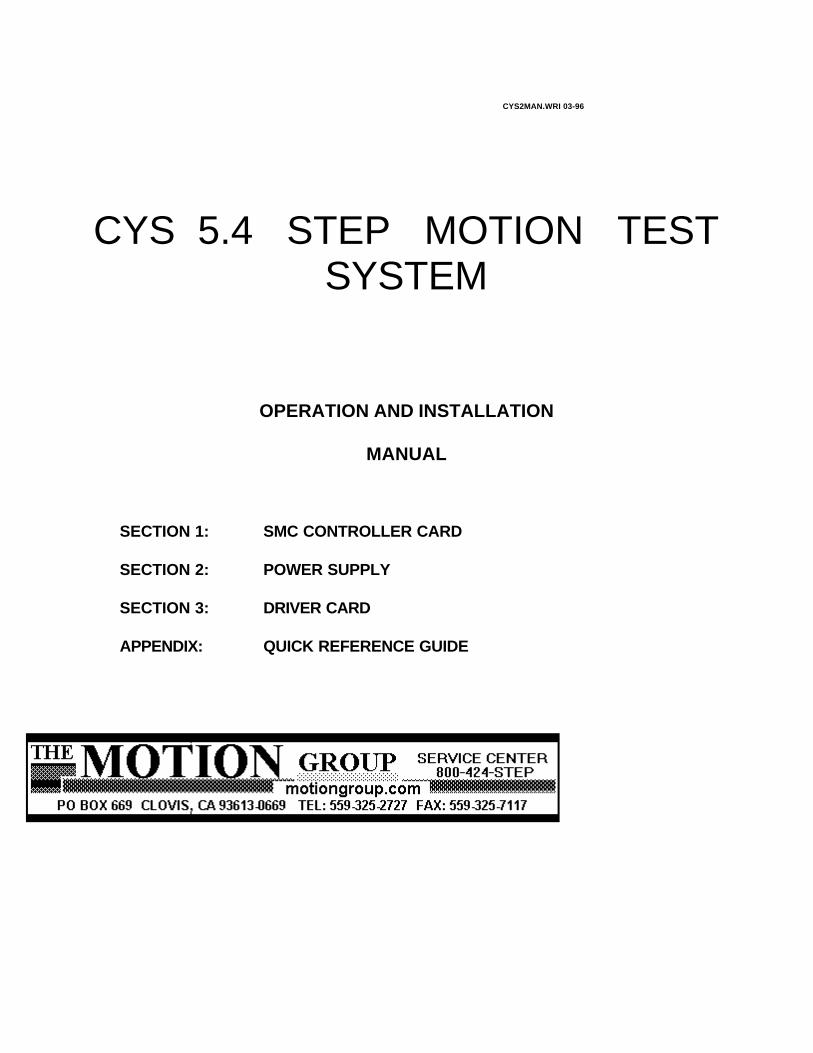
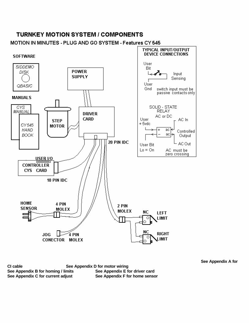
The CYS motion control system consists of three basic elements; the controller card, the driver card and their power supplies (VCC and VMM). The controller card (CY5.4) contains the Cybernetic CY 545 or CY 550 Step Motor Controller and a 2K character EEPROM (non-volatile) for storing application routines. Refer to the Cybernetics 545 manual for a description of the 545 microprocessor and its "High-Level" command set (26 characters and symbols). All actions of this system are controlled by these commands.
Two of the eight User Bits of the 545 (USRB 0-7) are assigned to a specific function. The remainder are for general purpose Input and Output functions (I / O) such as controlling relays or valves (output) and reading switches (input). The command set of the Cybernetic 545 contains instructions such as Test, Wait, Delay, Loop which are used along with the motion instructions to provide a wide range of machine operations. The CYS system can be discribed as a "mini-PLC with motion".
The Step pulses and the Direction signal from the CY5.4 controller are connected to the motor driver. Additionally, if required, the Stop signal shifts the driver from Park power to Full power. A Home Sensor channel is also part of the system.
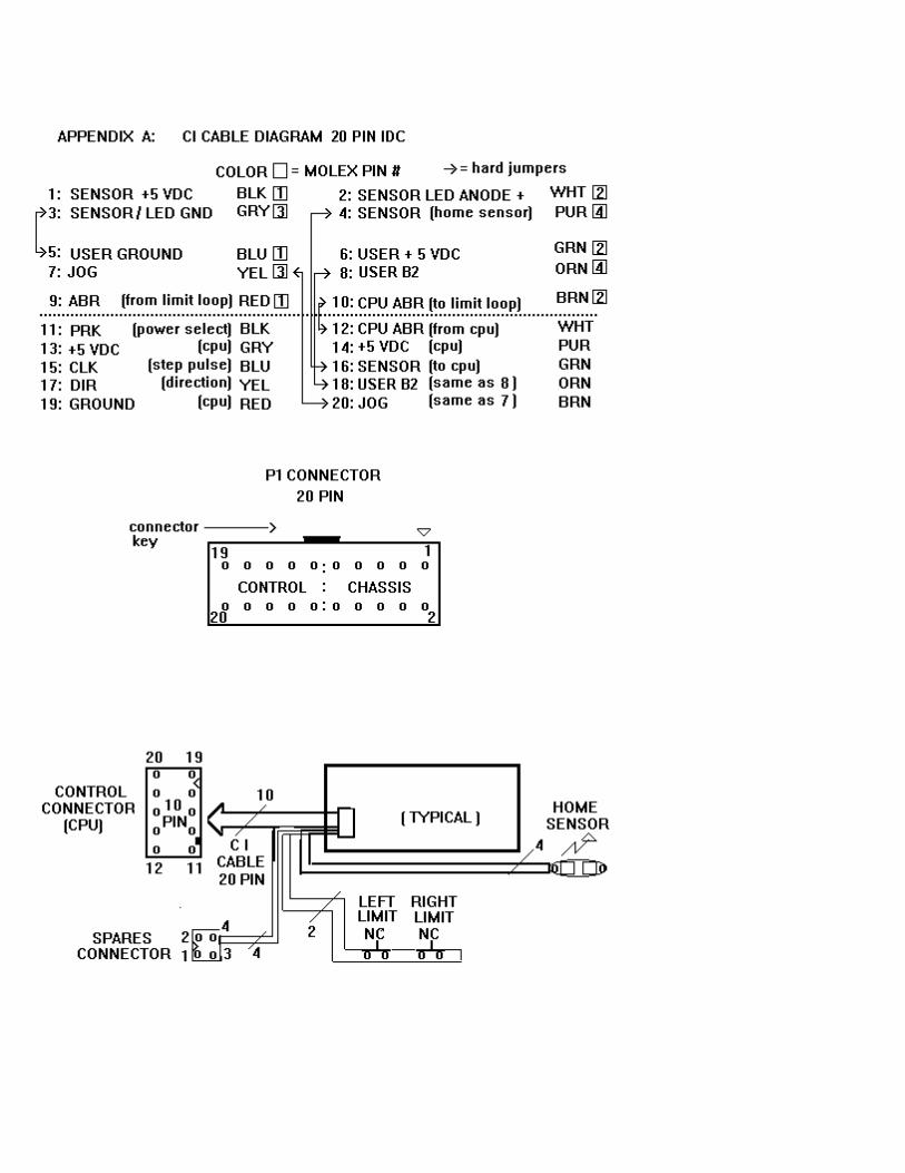
Each system includes a CI cable (controller interface cable). This 20 pin cable is divided into two sections. The Controller section contains + 5 v power and ground as well as the driver control signals. The Chassis section connects the Home Sensor, User Bit 2, Jog Switch, and Limit Loop signals back to the controller. Refer to Appendix A for details.
This system is self-contained and can operate independently or under the direct command of a host computer. In Memory Mode, the host computer is used to "teach" the system by sending a string of commands which are stored, for later execution, in the on-board memory of the controller card. In Direct Mode, the host commands are executed immediately by the CY545. A combination of these two modes is also possible; typically macro command strings are loaded to memory and then executed as required by the host.
Addition features are also available as options. These include an Encoder driven, absolute "Position Verification" unit, a Network (SR-4) controller which supports up to 64 channels of independent motion, or a Multiple Motor Adapter (MMA) which provides up to 128 channels of multiplexed motion.
CONTACT FACTORY FOR OPTION INFORMATION ON:
Encoder System ENC 1 (Position Verification) Expanded I/O option (26 pin I/O) Heavy Duty Connectors (Mil-Spec) Multiple Axis Controllers (MMC & MMA)Network Adaptor (SR4) RS-422 Serial Communication (twisted pair)
SMCOPERATION AND INSTALLATION
ALSO REFER TO:Cybernetic Micro Systems - CY 545 Step Motor Controller ManualCYSDEMO program - Software Listings & Comments
SECTION 1 CONTENTS PAGE
Introduction 1- 4Hardware Configuration 1- 7Displays & Controls 1- 8 Software Configuration 1- 9Installation & Test 1- 10 Programming & Listings 1- 12 Serial Cable Diagrams 1- 19
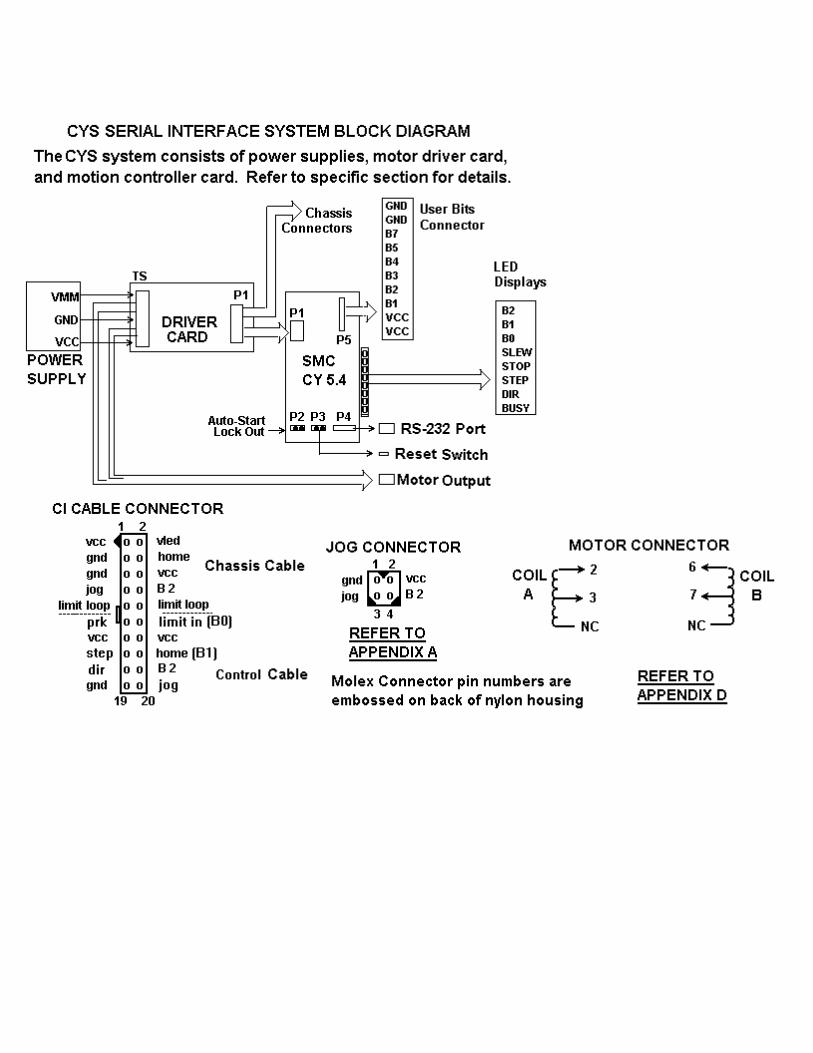
CY 545 COMMAND SET SUMMARY
Command Function Note
A val 24 set position counter to At value Commands are upper case ASCII letters,B bit # set or clear (/B) User Bit followed by a space, and a value if required.C set Continuous stepping mode Values without a suffix are 0 to 255 max. D val 16 Delay for value in milliseconds Values with 16 suffix are 65535 (64K) max.E Enter commands to user mem Values with 24 suffix are 16777215 (16 Meg). F val First (starting) speed of motor Add (byte count) is 64K max. Bit # is 0 to 7.G motor Goes the number of stepsH bit # Home motor on bit #I Initialize 545; software resetJ add Jump to address on mem pageL cnt add Loop to address for count valueN num 24 Number of steps; see GoO mode set mOdes of CY controllerP val 24 moves to an absolute PositionQ Quit Enter commands to memR val set Ramp (top) speed of motorS val Slope (acceleration) of F to RT bit # add jump to add unTil Bit matchesW bit # Wait at add until Bit matchesX eXecute commands at Y addY add 16 set mem address counter to YZ cnt 16 add Zillion Loops to add for cnt value0 (number) end of program or stop program+ ( plus ) set CW direction for Go move- ( minus ) set CCW direction for Go move/ ( forslash ) negate prefix for /Bit commands? command send back command val to host"message" send back message to host

!!!! ATTENTION !!!!Mis-wiring of motor or power supplies WILL damage motor drivers IMMEDIATELY. Motor coils A or B can be reversed; motor will run in the opposite direction. Pairs can be reversed; pair A in coil B for example. CROSS-WIRING, an A and B wire crossed, WILL damage driver. Allowing exposed motor leads to touch each other, ground, or power MAY damage driver. Refer to Appendix D in the MS driver section for wiring schemes.
SMOKE, POPPING, ELECTRONIC ODOR, OR FUSE FAILUREINDICATES DRIVER FAILURE.
Call the Service Center. Do NOT change fuse or attempt repair without instructions. ADDITIONAL DAMAGE CAN OCCUR !!! Shorted drivers can easily be repaired by replacing the socketed driver arrays.
!!!! WARNING !!!!NEVER connect or disconnect any of the motor leads or power supply (VMM) leads before disconnecting AC power! Unit may be safely operated WITHOUT motor. However, pause 30 seconds after power off before reconnecting motor (Bleed-Down time).
NOTE !An understanding of the Cybernetic Motion Controller and its Command Set is required in the following explainations . Refer to the Cybernetic Micro Systems - CY 545 OR 550 Step Motor Controller Manual.
CONTRARY TO POPULAR PRACTICE, IT IS BEST TO READ THIS MANUAL BEFORE ATTEMPTING TO OPERATE SYSTEM. IT WILL SAVE TIME AND PRODUCE BETTER, FASTER RESULTS.
HARDWARE CONFIGURATION
The SMC controller card contains the CY 545 motion controller, EEprom memory, memory latches (2 each), RS-232 receiver / driver, LED status lites and standard crystal (11 MHZ).
Serial Format. The SMC is connected as a RS-232 serial device and communicates with the host computer through the front panel DB-9 S connector (AT style). The serial format is configured in the following manner: ASCII characters, Adaptive Baud, 8 data bits, no parity, and one stop bit. The CTS (Clear To Send) feature of the 545 (User Bit 6) is used asthe hardware hand-shake to control communication between the host and the 545. When the 545 is busy, it will set the CTS to hold off transmission.
The SMC is configured that the CTS signal is busy when power is applied to the system. It is sometimes necessary to defeat this function when communicating with the system for the first time. There are two techniques. One is to set the Mode command (O) as part of the Auto-Start routine. The other is to OPEN with the CS = 0, send the mode command, and then re-OPEN with the CS set to the desired value. Refer to the software examples.
During operation from memory or when homing, the CTS function is not fully operational. This is to allow interruption of these routines by the host computer sending a stop command (0 or CR). If other data is sent, incorrect operation will result. To set the SMC 100% busy during operations; 1) disable the CTS function with a Mode command, 2) User Bit 6 will set HI or busy, and 3) as the last instruction, re-enable the CTS.
NOTE: the correct Mode command to defeat the CTS is: O 80H.the correct Mode command to enable the CTS is: O 0A0H
(Any Hex value starting with a letter must be preceded by a zero)
When the Busy feature is not required, for example during memory operation, then Bit 6 is available as a User I/O input bit.
Memory Format. The memory is configured as 2K bytes of EEPROM (RAM is optional). It is not possible to access memory above address 2047. Note that the memory is in pages of 256 bytes; the CY545 does not allow Jump, Test, or Loop operations across page boundries. The pointer command (Y) is used to move across boundries. A feature of the 545 memory system is the Auto-Start function which recognizes special character flags in the first bytes of memory as a command to run the following program at power-on.Home Function. This system uses an optical sensor to establish the starting reference or "Home" position at power-on; refer to the Home command (H). Lash-Compensation is included in the home routine. A major advantage of this system is Slip-Detection which provides operation to + zero steps. See Installation and Test for a detailed home procedure.
Limit Loop Function. The CW-CCW Limits function of the 545, pin 4 & 5, is not used in this system. Instead, the driver card will go "free or ABoRt" (CURRENT-OFF) when the Limit Loop is opened (Fail-Safe, Hard-Soft limits). This Limit Loop is enabled by User Bit 0. Refer to Appendix B of the driver card section of this manual. Note that the CW-CCW inputs are available in this system as the Emergency Stop option. Also, the Inhibit / Abort (pin 8) is not used in this system. This Abort is not the same as the driver abort (ABR). Note that Abort is available, in this system, as the Ramp-To-Stop option.
I/O Function. The Cybernetic User Bits are available at the CI cable connectors and can be used as either inputs or outputs dependent on the command. Note that an output can only drive LEDs such as those in Solid-State relays or optical isolation. An input can only be a passive switch or isolated relay contact across the User Bit and User ground. Connecting any device, at a different potential, to this system through the User Bits, WILL damage the User port; opto-isolation is required. External thumbwheel (pin 12) is not used. Instead refer to the I/O Path option for thumbwheel operation or stand-alone (PLC) mode. The standard CI cable is the 20 pin which provides limits and home sensor signals, access to the User Bit I/O lines, and VCC power & ground. Refer to Appendix A of this manual.
Other Functions. The Jog function (pin 6) is available at the Jog connector of the CI Cable; see Appendix A.
Reserved User Bits.B 0 Enable Driver; must be Lo to step. B0 LED will be ON.B 1 Bit 1 is always the Home Sensor.B 6 Bit 6 Is the Busy Bit (CTS) option. See mOde Command. Bit 6
can also be used, typically in stand-alone applications, as an input.
Displays.OFF = Logic High or true ON = Low or false; pin # refers to CY 545 pinout.
BZ Indicates the inverse of pin 27(User Bit 6) Off = Ready;On = BusyDR Indicates the polarity of pin 2 (direction) Lo = CW ST Indicates the polarity of pin 1 (step) Lo = Step pulsePW Indicates the polarity of pin 3 (stop) Lo = SteppingSW Indicates the polarity of pin 6 (slew) Lo = Ramp speedB0 Indicates the polarity of pin 21 (User Bit 0) Lo = Enable all driversB1 Indicates the polarity of pin 22 (User Bit 1) Lo = Home Sensor blockedB2 Indicates the polarity of pin 23 (User Bit 2) General Purpose User Bit
Reset Switch. Pushing the reset switch causes a hardware reset (pin 9).
SOFTWARE CONFIGURATION
This system is a serial periferal device directed by ASCI character commands. It is configured exactly as described in the Cybernetics controller manuals; except for those differences as noted in this manual. Special Commands are created to simplify use of the Basic program.
Reserved and Special Software Commands.
CLEAR Writes 0's and CR's to memory.LOAD [F6] Loads memory. Not same function as Basic F3 key.EXIT [F5] Required to close comm port, close file, and clear error traps.comma [,] Do not use comma to separate elements of 545 commands (T,L, and ? M xx).
Comma is a Basic symbol; use space.[a,b,c] HP-LED command string is not used.C Continuous Step Mode is normally not used with the CY545 unless motion can be terminated with an external Abort signal. Refer also to the CY550 which is an advanced version which has a larger selection of on-the-fly software commands.? E Software command which returns encoder position.
Special Aspects of Some Commands.
W The Wait command causes the 545 to wait at the instruction,therefore incoming stop commands will not be processed. Use a Tcommand in a jump to itself.
L, Z These loop instructions assume that the first pass of a routine before reaching the loop command was the 1st loop pass. In general, the loop count must be one less than required. Also
see J & T below.
T,H,W These commands are followed by a numeric value in Hexdecimalwhich is desinated by the H following the value. The decimal andthe hex values for 0 to 7 are the same and the H is omitted.
H Homing is a single step operation. The Busy signal is not continuously set during homing but cycles every step. It is best therefore that homing is executed from memory.
J, T Any Jump or Test operation, which includes L & Z commands, must not cross the memory page boundry which is ever 256
bytes; 256, 512, 768, 1024, etc. Use the Y for global jumps.
INSTALLATION AND SELF-TEST PROCEDURE
1. Connect AC power cord.2. Connect motors, verify that driver current is correct for motors. See
Appendix C for current adjustment and Appendix D for motor wiring.3. Connect CI cable. Limit Loop must be closed for motor to run.4. Connect the serial cable and turn-on computer system. Do NOT run the computer program at this time. 5. Connect the AC power and turn-on power switch or supplies. Verify
that: AC neon; power is present. DC lamp; motor power (VMM) is OK.
System will run the Auto-Start self-test program as described in the listings; EEPROM sample program. Refer to lines 1000-1800 of the listings in this manual. This test proves that the CYS system is operating correctly. Note, this demo will include "homing". The motor will run backwards until the home sensor is blocked (block the sensor with a pencil tip). Then, typically, motor will run back and forth several times. To defeat the self-test, refer to Auto-Start Lockout procedure later in this section. Observe the LED indicator lites while the test is running and note that each action of the system can be monitored and that this self-test is the series of commands listed between the quotes in lines 1000-1800. All actions of the system are the result of COMMANDS, refer to the back cover of the CY 545 manual, either stored in the external memory (Memory Mode) or sent from the host computer (Direct Mode). The third mode (Programming Mode) is when commands are sent from the host and written into the external memory.
COMPUTER TEST PROCEDURE
1. Wait till Auto-Start self-test has completed; B2 LED comes on; PW LED is off.2. LOAD and RUN the Demo program which will down-load another self-test. Refer to lines 400-800 of the listings. The system will return position when finished: P= 000000 NOTE: If the return is in segments: P=
0000
00exit the program (F5), refer to line 120, and set the correct timebase (T value) for the host computer. Re-start (shift-F5) the program.
NOTE: If the message "system is busy or not connected....." appears, enter Ctrl-Break. The system IS busy (self-test ?) or NOT connected to COMM 1. RESET the CYS and allow self-test to finish or correct the serial cabling.
3. Motor Commands.
NOTE: Enter commands (Direct Mode), at the prompt;Caps Lock on; < = the Enter key; F x = function key.
F9 the CYS returns position; this indicates communication is OK/B 0< enables motor, B 0 LED is ON or LOH 1< motor 0 will home until the sensor is blockedP 2000< motor will move to position 2000 ( 2000 steps CW )F9 ? P returns P=0002000; position is 2000P 0< motor returns to position 0B 0< free motor

4. Memory Commands.
F7 ? Y where is memory byte pointer; Y=xxxx is last byte of self-testY 0< sets pointer to byte location 0? m 22< displays 22 "command lines" of memory (F8 and type 22<)
Note the Auto-Start flags, arrow, 4, V, at byte location 0,1,2 (refer to lines 1030,1040,1050);followed by the first command, O 80H (mode = BUSY, line 1060).
CLEAR< fill the memory with 0's and carriage returns; STOP commandsY< yes; wait till 0 0 0 0....DONE. F7 Y=0000F8 22< memory is clearedF6 load memory; host goes to line 1000; returns ? P when doneF7 Y=xxxx; last byte of programY 0< set memory byte pointer to byte 0F8 22< memory is loadedCLEAR<Y< remove the Auto-Start program at this time, if desired
Auto-Start Defeat. In the event an in-correct program is loaded to the memory, and/or the system locks-up in Auto-Start, it is necessary to manually by-pass the Auto-Start: A) Locate the Auto-Start Lockout pins; through the 1/4" hole, left CYSe corner,
above the motor label.B) Carefully, short the pins with a #2 phillips driver tip or ballpoint pen.C) While maintaining the short, Reset the controller. Controller will by-pass
the Auto-Start program.D) Remove the short. Re-start (shift-F5) the computer demo and CLEAR or
over-write the memory program.It is good practice NOT to arm the Auto-Start flags before a program has been tested using the Y address and X commands. When using the demo program, simply REMark out the flags and change the starting address from Y = 0 to Y = 3; reserves three bytes.
Parameterizing. Refer to the CY 545 MANUAL, SECTIONS 1-12 (Commands), 16 (see StepMotor and Home), 17 (Rate Tables), 19 (good sample program); sections 13,14,15 not used. Typical commands will duplicate the down-load with different values of R, S, and F used in order to determain the best parameters for moving the motor. Refer to the Rate Tables. Repeat Step 3 with different parameters.
Resonance. Resonance (feed-back oscillation between the motor rotor and the motor coils) is a vibration which affects the motor behavior. Typical symptions are shuttering, dropping steps, jumping back and forth, hard running, and excessive noise (unpleasent). All step motors exibit resonance at approximately 100 full step/sec (Low Frequency) and at 1000 full steps/sec (Mid Frequency). This behavior is affected by motor load, power, and speed. The normal procedure is to start at a speed (F command) above the low point and ramp through the mid point (S command) to a higher speed (R command).
To determine the resonance points, set F and S to the lowest value and R above mid freq. Move the motor sufficent steps to reach top speed. Note the points during this acceleration where the motor exhibits abnormal behavior; these are the low frequency nodes. The motor will stall at the mid freq. point. Resonance can be reduced by less power, decoupling the motor and load (isolating couplers; not metal to metal), higher speeds, faster acceleration, and/or smaller step angles.

PROGRAMMINGThe software program used with the CYS system is only a "Serial Driver" routine. The main purpose of the program is to send and receive commands between the host and the CY 545 microprocessor. The motion control software (firmware) is contained only in the 545. The serial driver contain examples of typical operations required by the host computer software, such as: opening the comm (serial) port, sending/receiving characters, loading the 545 memory, handling the Busy (CTS), and diagnostic capability. Included in the sample program are routines of 545 commands which exercise the motion system during manufacturing tests. Two types of routines are demonstrated; (1) downloading a string of commands from a keyboard file and (2) loading a string of commands to EEprom memory. The memory routine example is an Auto-Start program refered to as a Self-Test. This routine will run when the system is powered-on as proof that the system is operating correctly.
The sample listing is commented and contains information about how to operate a 545 system. It is helpful to "read the listing" even for non-computer types.
Line 0-20 defines the variables and create symbols for control characters.
Line 30-100 assigns the Basic function keys for common functions.
Line 120 creates the time delay used between characters so that fast computers do not get ahead of the serial card and the 545.
Line 130 defines the serial port as the ACTIVE device; PRINT #ACTIVE sends characters to the active port. Line 200-400 creates the introduction screen display
Line 500-999 is the down-load test routine which is sent to the 545 when this program is first run.
Line 1010-1410 is the Self-Test program shipped in the system EEprom. Note that lines 1030-1050 send the Auto-Start flags in their decimal values. The semi-colons inhibit the carriage return (Enter) until the colon at Line 1060. Refer to the CY 545 manual for the Auto-Start format. The GOSUB 2500 is the time delay for the write cycle of the EEprom memory.
Line 1500-1800 is a sample homing routine with a limited number of re-tries; loop counter, input test, and message transmission are demonstrated in this program.
Line 1800 asks the 545 a question (? P command). The return of the answer from the 545 indicates that the system is responing to the host.
Line 2000-2510 assemblies keyboard entries and sends them to the 545 at the Enter key ( CR = carriage return or enter key). Note the special commands at line 2210-2270 which are created commands not part of the 545 command set.
Line 2600-2750 reads any incomming characters from the 545 and prints to the host display screen.
Line 2910-3000 closes the comm ports on Exit (F5) or a computer error code other than ERROR = 24 (comm port is busy).
Line 3000-3150 writes zeros (545 stop command) and carriage returns over the entire memory (Clear command) which erases the memory. The opposite is the Load command which writes the memory.
Line 3300-3400 is the busy error routine.
Line 4000- are the help files.
PROGRAM LISTINGS5 PRINT "CYSDEMOB SERIAL INTERFACE DEVICE DEMO PROGRAM REV D 2-10-95"
10 DEFINT A-Z: REM DEFAULT ALL INTEGERS
20 LF$ = CHR$(10): NL$ = CHR$(0): ES$ = CHR$(27): CR$ = CHR$(13): BK$ = CHR$(8): QT$ = CHR$(34)
30 KEY OFF
40 KEY 10, CR$: REM SAVE LAST COMMAND ON SCREEN
50 KEY 9, "? P" + CR$: REM SEND ? P
60 KEY 7, "? Y" + CR$: REM SEND ? Y
70 KEY 8, "? M 22" + CR$: REM SEND ? M and space [add 22 bytes max & cr]
80 KEY 6, "LOAD" + CR$: REM LOAD EEPROM PROGRAM TO MEMORY
90 KEY 5, "EXIT" + CR$: REM EXIT THIS PROGRAM
100 KEY ON
110 CLS : REM XT=50 AT=150 386=300 486=500 TIME BASE VALUE
120 T0 = 300: REM SELECT BASE TIME DELAY FOR COMPUTER SPEED USED
130 ACTIVE = 1: REM DEFAULT COMM PORT ASSIGNMENT
131 ON ERROR GOTO 3300: REM ERROR ROUTINE AT LINE 3300
140 OPEN "COM1:9600,N,8,1,CS000,DS0,CD0" FOR RANDOM AS #1: REM CS SET TO 0 SEC
141 PRINT #1, CR$; CR$; : REM SEND AUTOBAUD CARRIAGE RETURNS TO COM 1
142 PRINT #1, "O 0A0H": REM SET MODE COMMAND-AUTOMATIC BUSY FUNCTION-ARM BIT 6
143 CLOSE #1
144 OPEN "COM1:9600,N,8,1,CS1000,DS0,CD0" FOR RANDOM AS #1: REM CS SET TO 1 SEC
145 PRINT #1, CR$; CR$; : REM SEND AUTOBAUD CARRIAGE RETURNS TO COM 1
150 REM OPEN "COM2:9600,N,8,1,CS000,DS0,CD0" AS #2 REM REMOVE REM'S TO OPEN COM2 SEE LINE 291
151 REM PRINT #2,CR$;CR$;: REM SEND AUTOBAUD CARRIAGE RETURNS TO COM 2
152 REM PRINT #2,"O 0A0H": REM SET MODE COMMAND-BUSY FUNCTION - ARM BIT 6
153 REM CLOSE #2
154 REM OPEN "COM2:9600,N,8,1,CS1000,DS0,CD0" AS #2: REM CS = 1 SEC
155 REM PRINT #2,CR$;CR$;: REM SEND AUTOBAUD CARRIAGE RETURNS TO COM 2
160 ON ERROR GOTO 3300:
200 LOCATE 5, 1, 1
210 PRINT " THE MOTION GROUP - SERIAL MOTOR DRIVER - MODEL CYS w/ CY 545B"
220 PRINT "*********************************************************************"
230 PRINT "**READY TO GO** 9600 BAUD N0 PARITY 8 DATA BITS 1 STOP BIT CS=1 SEC SEE LINE 140 AND 150 FOR OPEN COM STATEMENTS"
240 PRINT " SEE ADDITIONAL LINES FOR AUTOBAUD AND BUSY MODE COMMANDS "
250 PRINT " SEE LINE 500 FOR INITIAL DOWN LOAD PROGRAM "
260 PRINT " SEE LINE 1000 FOR EEPROM PROGRAM "
270 PRINT " TYPE CLEAR TO ERASE EEPROM MEMORY "
280 PRINT " USE LOAD [F6] TO LOAD EEPROM MEMORY. F8 TO DISPLAY EEPROM "
290 PRINT " USE Esc OR F5 KEY TO EXIT THIS PROGRAM CORRECTLY "
300 PRINT " BIT 0 ENABLES DRIVER MUST BE LOW TO STEP "
310 PRINT " BIT 1 IS HOME SENSOR - see HOME command "
320 PRINT " BIT 2-5,7 ARE USER BITS "
330 PRINT " BIT 6 IS RS 232 BUSY BIT - used to lock out CPU commands when BUSY "
350 PRINT " "
360 PRINT "Enter commands, at prompt, only after autoboot EEPROM program and initial down load program has completed execution and returned
position P=0000000 "
370 PRINT "Type HELP for help screen "

380 PRINT " "
390 PRINT " Note| Use RESET switch to STOP SYSTEM; Esc Key = Exit program "
400 PRINT " DOWN-LOAD DEMO IN PROGRESS; WAIT FOR P=0000000 "
410 REM GOTO 1800: REM Remove REM to skip Down-Load sample
500 REM ******* START OF INITIAL DOWNLOAD COMMANDS PROGRAM ****************
501 REM ******* TYPICAL SERIES OF GENERAL COMMANDS AS A TEST OF MOTION SYSTEM
510 PRINT #ACTIVE, "R 125": REM SEND RATE 125
520 PRINT #ACTIVE, "S 225": REM SEND SLOPE 225
530 PRINT #ACTIVE, "F 15": REM SEND FIRST RATE 15; 30 FOR QUAD STEPers
540 PRINT #ACTIVE, "/B 0": REM SEND SET BIT 0 LOW; ENABLE DRIVER POWER
550 PRINT #ACTIVE, "N 800": REM SEND NUMBER OF STEPS 800
560 PRINT #ACTIVE, "G": REM GO NUMBER OF STEPS
570 PRINT #ACTIVE, "/B 2": REM SET BIT 2 LOW
580 REM PRINT #ACTIVE, "H 1": REM HOME ON B1 - HOMING COMMAND DISABLED
585 PRINT #ACTIVE, "A 1": REM DECLARE CURRENT POSITION AS P = 1
590 PRINT #ACTIVE, "P 0": REM SEND 'MOVE TO POSITION 0'
600 PRINT #ACTIVE, "P 1000": REM SEND 'MOVE TO POSITION XXXXX'
610 PRINT #ACTIVE, "P 0": REM MOVE TO POSITION 0
620 PRINT #ACTIVE, "P 1000": REM MOVE TO POSITION XXXXX
630 PRINT #ACTIVE, "P 0": REM MOVE TO POSITION 0
640 PRINT #ACTIVE, "P 1000": REM MOVE TO POSITION XXXXX
650 PRINT #ACTIVE, "P 0": REM MOVE TO POSITION 0
660 PRINT #ACTIVE, "/B 3": REM SET BIT 3 LOW
670 PRINT #ACTIVE, "P 1000": REM MOVE TO POSITION XXXXX
680 PRINT #ACTIVE, "P 0": REM MOVE TO POSITION 0
690 PRINT #ACTIVE, "/B 4": REM SET BIT 4 LOW
700 PRINT #ACTIVE, "P 1000": REM MOVE TO POSITION XXXXX
710 PRINT #ACTIVE, "P 0": REM MOVE TO POSITION 0
720 PRINT #ACTIVE, "/B 5": REM SET BIT 5 LOW
730 PRINT #ACTIVE, "P 0": REM MOVE TO POSITION 0
740 PRINT #ACTIVE, "P 1000": REM MOVE TO POSITION XXXXX
750 PRINT #ACTIVE, "P 0": REM MOVE TO POSITION 0
760 PRINT #ACTIVE, "/B 7": REM SET BIT 7 LOW
770 PRINT #ACTIVE, "P 1000": REM MOVE TO POSITION XXXXX
780 PRINT #ACTIVE, "P 0": REM MOVE TO POSITION 0
790 PRINT #ACTIVE, "/B 2": REM SET BIT 2 LOW
800 PRINT #ACTIVE, "+": REM SET DIRECTION +
810 GOTO 1800: REM GO TO ENTER COMMAND PROMPT
1000 REM ******** SAMPLE PROGRAM - EEPROM MEMORY ********
1001 REM Modify the commands between the quotes ********
1002 PRINT "LOADING SAMPLE PROGRAM SEE LINE 1000 WAIT FOR P=0000000"
1010 PRINT #ACTIVE, "Y 0": T = T0: GOSUB 2500: REM SET STARTING MEM ADDRESS
1011 REM T value delay, required if EEPROM is installed - 10 MS write cycle
1020 PRINT #ACTIVE, "E": GOSUB 2500: REM Enter programming mode {save to EEPROM}
1030 PRINT #ACTIVE, CHR$(18); : GOSUB 2500: REM AUTOSTART FLAG 12H - ADD 00
1040 PRINT #ACTIVE, CHR$(52); : GOSUB 2500: REM AUTOSTART FLAG 34H - ADD 01
1050 PRINT #ACTIVE, CHR$(86); : GOSUB 2500: REM AUTOSTART FLAG 56H - ADD 02
1060 PRINT #ACTIVE, "O 80H": GOSUB 2500: REM SET MODE COMMAND;CTS OFF (BUSY
1061 REM * NOTE * Sets system busy {BIT 6} to lockout CPU commands during
CY 545 program execution from memory. See Mode {O} Command.
1070 PRINT #ACTIVE, "R 100": GOSUB 2500: REM RATE = 100

1080 PRINT #ACTIVE, "F 150": GOSUB 2500: REM FIRST RATE = 15; FAST HOMING
1090 PRINT #ACTIVE, "S 255": GOSUB 2500: REM SLOPE = 255
1100 PRINT #ACTIVE, "/B 0": GOSUB 2500: REM B0 LO = ENABLE DRIVER OUTPUT
1110 PRINT #ACTIVE, "H 1": GOSUB 2500: REM HOME MOTOR ON B1
1120 PRINT #ACTIVE, "A 1": GOSUB 2500: REM DECLARE HOME POSITION AS P=1
1130 PRINT #ACTIVE, "F 15": GOSUB 2500: REM NEW FIRST RATE FOR RUNNING
1140 PRINT #ACTIVE, "P 6400": GOSUB 2500: REM MOVE TO P=6400; GO +6400 STEPS
1150 PRINT #ACTIVE, "D 900": GOSUB 2500: REM DELAY 1 SEC (11MHZ CLOCK)
1160 PRINT #ACTIVE, "P 3200": GOSUB 2500: REM MOVE TO POSITION XXXX
1170 PRINT #ACTIVE, "D 900": GOSUB 2500: REM DELAY 1 SEC
1180 PRINT #ACTIVE, "P 1600": GOSUB 2500: REM MOVE TO POSITION XXXX
1190 PRINT #ACTIVE, "D 900": GOSUB 2500: REM DELAY 1 SEC
1200 PRINT #ACTIVE, "P 800": GOSUB 2500: REM MOVE TO POSITION XXXX
1210 PRINT #ACTIVE, "D 900": GOSUB 2500: REM DELAY 1 SEC
1220 PRINT #ACTIVE, "P 400": GOSUB 2500: REM MOVE TO POSITION XXXX
1230 PRINT #ACTIVE, "D 900": GOSUB 2500: REM DELAY 1 SEC
1240 PRINT #ACTIVE, "P 200": GOSUB 2500: REM MOVE TO POSITION XXXX
1250 PRINT #ACTIVE, "D 900": GOSUB 2500: REM DELAY 1 SEC
1260 PRINT #ACTIVE, "P 0": GOSUB 2500: REM MOVE TO POSITION XXXX
1270 PRINT #ACTIVE, "R 150": GOSUB 2500: REM SET NEW TOP SPEED; BIG MOVE!
1280 PRINT #ACTIVE, "P 20000": GOSUB 2500: REM MOVE TO POSITION XXXX
1290 PRINT #ACTIVE, "D 900": GOSUB 2500: REM DELAY 1 SEC
1300 PRINT #ACTIVE, "P 0": GOSUB 2500: REM HOME LED (B1) ON
1310 PRINT #ACTIVE, "D 2000": GOSUB 2500: REM DELAY 2 SEC
1320 PRINT #ACTIVE, "P 1": GOSUB 2500: REM HOME LED OFF; BLINKS
1330 PRINT #ACTIVE, "D 2000": GOSUB 2500: REM DELAY 2 SEC
1340 PRINT #ACTIVE, "P 0": GOSUB 2500: REM HOME LED (B1) ON
1350 PRINT #ACTIVE, "D 2000": GOSUB 2500: REM DELAY 1 SEC
1360 PRINT #ACTIVE, "+": GOSUB 2500: REM SET DIRECTION CW; DIR LED ON
1370 PRINT #ACTIVE, "D 1000": GOSUB 2500: REM DELAY 1 SEC
1380 PRINT #ACTIVE, "/B 2": GOSUB 2500: REM SET B2 LO; DONE SIGNAL
1390 PRINT #ACTIVE, "O 0A0H": GOSUB 2500: REM Restore BUSY to active state
1400 PRINT #ACTIVE, "0": GOSUB 2500: REM Stop. Return to Direct mode
1410 PRINT #ACTIVE, "Q": GOSUB 2500: REM Quit programming mode
1500 REM **** SAMPLE HOMING ROUTINE WITH LIMITED NUMBER OF ATTEMPTS******
1510 PRINT #ACTIVE, "Y 600": T = T0: GOSUB 2500: REM TYPICAL STARTING MEM ADD
1520 PRINT #ACTIVE, "E": GOSUB 2500: REM Enter programming mode {save to EEPROM}
1570 PRINT #ACTIVE, "Z 1 600": GOSUB 2500: REM BYTE 600 EMPTY Z COUNTER
1580 PRINT #ACTIVE, "F 150": GOSUB 2500: REM FIRST RATE = 150; FAST HOMING
1590 PRINT #ACTIVE, "N 1": GOSUB 2500: REM NUMBER OF STEPS = 1
1600 PRINT #ACTIVE, "/B 0": GOSUB 2500: REM B0 LO = ENABLE DRIVER OUTPUT
1610 PRINT #ACTIVE, "T 01H 667": GOSUB 2500: REM BYTE 623 TEST SENSOR FOR HI; IF LO GO TO BYTE 667
1620 PRINT #ACTIVE, "-": GOSUB 2500: REM SENSOR WAS HI (NOT HOME) GO CCW
1630 PRINT #ACTIVE, "G": GOSUB 2500: REM GO CCW 1 STEP
1640 PRINT #ACTIVE, "D 03": GOSUB 2500: REM DELAY SETS HOMING SPEED
1650 PRINT #ACTIVE, "Z 1000 623": GOSUB 2500: REM LOOK FOR HOME 1000 TIMES (LENGTH OF AXIS
1660 PRINT #ACTIVE, QT$ + "CCW FAIL" + QT$ + "B 0": GOSUB 2500: REM FAIL MESSAGE
1663 PRINT #ACTIVE, "Z 1 667": GOSUB 2500: REM BYTE 667 EMPTY Z COUNTER
1665 PRINT #ACTIVE, "T 11H 717": GOSUB 2500: REM BYTE 675 TEST SENSOR FOR LO; GOTO BYTE 717=DONE
1670 PRINT #ACTIVE, "+": GOSUB 2500: REM STEP CW UNTIL ONE STEP PAST SENSOR
1680 PRINT #ACTIVE, "G": GOSUB 2500: REM GO 1 STEP
1690 PRINT #ACTIVE, "D 03": GOSUB 2500: REM DELAY SETS HOMING SPEED
1700 PRINT #ACTIVE, "Z 100 675": GOSUB 2500: REM LOOK FOR HOME 100 TIMES
1710 PRINT #ACTIVE, QT$ + "CW FAIL" + QT$ + "B 0": GOSUB 2500: REM FAIL MESSAGE
1720 PRINT #ACTIVE, "A 1": GOSUB 2500: REM BYTE 717 SET LASH COMPENSATION VALUE (P=00000001
1725 PRINT #ACTIVE, "F 15": GOSUB 2500: REM RESTORE FIRST RATE FOR NORMAL STEPPING
1730 PRINT #ACTIVE, "0": GOSUB 2500: REM END PROGRAM(MING)
1740 PRINT #ACTIVE, "Q": GOSUB 2500: REM QUIT PROGRAMMING MODE

1800 A$ = "? P": T = T0: REM Query Position - Indicates completed MEM LOAD
1810 GOTO 2280: REM SEND 'QUERY POSITION' TO DRIVER
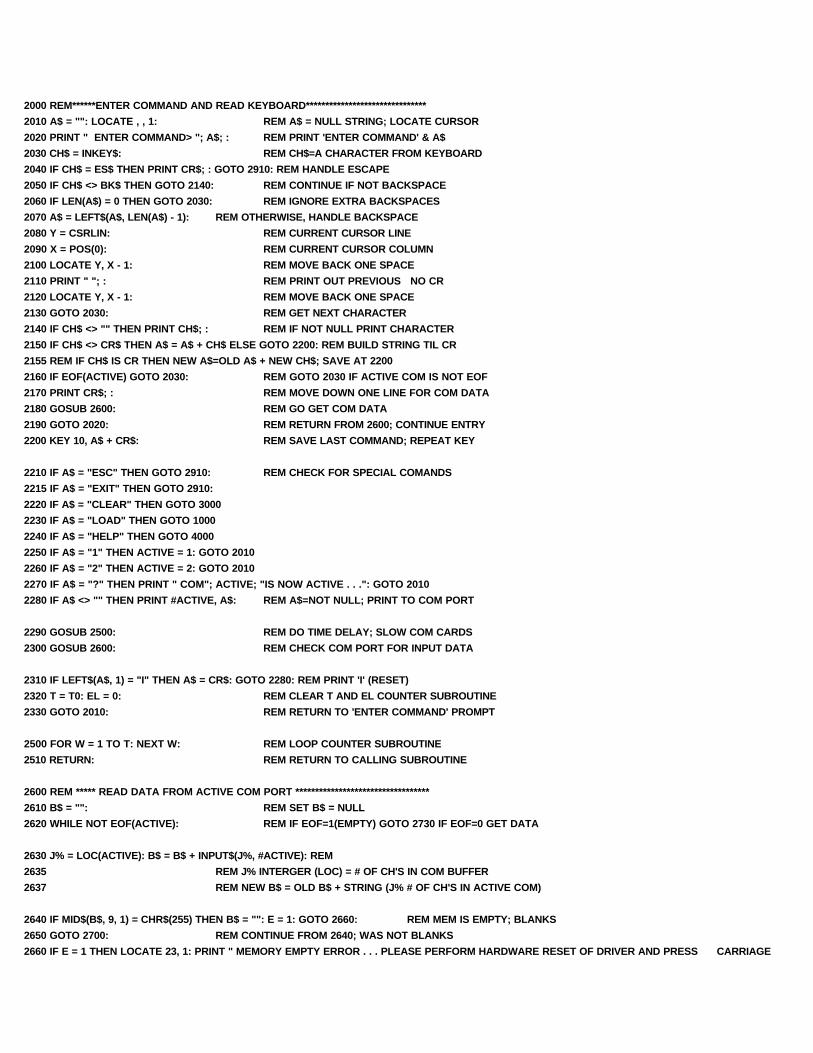
2000 REM******ENTER COMMAND AND READ KEYBOARD*******************************
2010 A$ = "": LOCATE , , 1: REM A$ = NULL STRING; LOCATE CURSOR
2020 PRINT " ENTER COMMAND> "; A$; : REM PRINT 'ENTER COMMAND' & A$
2030 CH$ = INKEY$: REM CH$=A CHARACTER FROM KEYBOARD
2040 IF CH$ = ES$ THEN PRINT CR$; : GOTO 2910: REM HANDLE ESCAPE
2050 IF CH$ <> BK$ THEN GOTO 2140: REM CONTINUE IF NOT BACKSPACE
2060 IF LEN(A$) = 0 THEN GOTO 2030: REM IGNORE EXTRA BACKSPACES
2070 A$ = LEFT$(A$, LEN(A$) - 1): REM OTHERWISE, HANDLE BACKSPACE
2080 Y = CSRLIN: REM CURRENT CURSOR LINE
2090 X = POS(0): REM CURRENT CURSOR COLUMN
2100 LOCATE Y, X - 1: REM MOVE BACK ONE SPACE
2110 PRINT " "; : REM PRINT OUT PREVIOUS NO CR
2120 LOCATE Y, X - 1: REM MOVE BACK ONE SPACE
2130 GOTO 2030: REM GET NEXT CHARACTER
2140 IF CH$ <> "" THEN PRINT CH$; : REM IF NOT NULL PRINT CHARACTER
2150 IF CH$ <> CR$ THEN A$ = A$ + CH$ ELSE GOTO 2200: REM BUILD STRING TIL CR
2155 REM IF CH$ IS CR THEN NEW A$=OLD A$ + NEW CH$; SAVE AT 2200
2160 IF EOF(ACTIVE) GOTO 2030: REM GOTO 2030 IF ACTIVE COM IS NOT EOF
2170 PRINT CR$; : REM MOVE DOWN ONE LINE FOR COM DATA
2180 GOSUB 2600: REM GO GET COM DATA
2190 GOTO 2020: REM RETURN FROM 2600; CONTINUE ENTRY
2200 KEY 10, A$ + CR$: REM SAVE LAST COMMAND; REPEAT KEY
2210 IF A$ = "ESC" THEN GOTO 2910: REM CHECK FOR SPECIAL COMANDS
2215 IF A$ = "EXIT" THEN GOTO 2910:
2220 IF A$ = "CLEAR" THEN GOTO 3000
2230 IF A$ = "LOAD" THEN GOTO 1000
2240 IF A$ = "HELP" THEN GOTO 4000
2250 IF A$ = "1" THEN ACTIVE = 1: GOTO 2010
2260 IF A$ = "2" THEN ACTIVE = 2: GOTO 2010
2270 IF A$ = "?" THEN PRINT " COM"; ACTIVE; "IS NOW ACTIVE . . .": GOTO 2010
2280 IF A$ <> "" THEN PRINT #ACTIVE, A$: REM A$=NOT NULL; PRINT TO COM PORT
2290 GOSUB 2500: REM DO TIME DELAY; SLOW COM CARDS
2300 GOSUB 2600: REM CHECK COM PORT FOR INPUT DATA
2310 IF LEFT$(A$, 1) = "I" THEN A$ = CR$: GOTO 2280: REM PRINT 'I' (RESET)
2320 T = T0: EL = 0: REM CLEAR T AND EL COUNTER SUBROUTINE
2330 GOTO 2010: REM RETURN TO 'ENTER COMMAND' PROMPT
2500 FOR W = 1 TO T: NEXT W: REM LOOP COUNTER SUBROUTINE
2510 RETURN: REM RETURN TO CALLING SUBROUTINE
2600 REM ***** READ DATA FROM ACTIVE COM PORT **********************************
2610 B$ = "": REM SET B$ = NULL
2620 WHILE NOT EOF(ACTIVE): REM IF EOF=1(EMPTY) GOTO 2730 IF EOF=0 GET DATA
2630 J% = LOC(ACTIVE): B$ = B$ + INPUT$(J%, #ACTIVE): REM
2635 REM J% INTERGER (LOC) = # OF CH'S IN COM BUFFER
2637 REM NEW B$ = OLD B$ + STRING (J% # OF CH'S IN ACTIVE COM)
2640 IF MID$(B$, 9, 1) = CHR$(255) THEN B$ = "": E = 1: GOTO 2660: REM MEM IS EMPTY; BLANKS
2650 GOTO 2700: REM CONTINUE FROM 2640; WAS NOT BLANKS
2660 IF E = 1 THEN LOCATE 23, 1: PRINT " MEMORY EMPTY ERROR . . . PLEASE PERFORM HARDWARE RESET OF DRIVER AND PRESS CARRIAGE

RETURN AND CLEAR MEMORY.";
2670 PRINT #ACTIVE, CR$; : REM RESTORE AUTO BAUD
2680 PRINT #ACTIVE, CR$; : REM WITH TWO CR'S
2690 GOTO 2720: REM EXIT MEM EMPTY LOOP
2700 E = 0: REM RESET E FLAG
2710 FOR W = 1 TO T: NEXT W: REM WHILE LOOP FOR MORE COM DATA UNTIL W=0
2720 WEND: REM END OF WHILE SUBROUNTINE DO NEXT
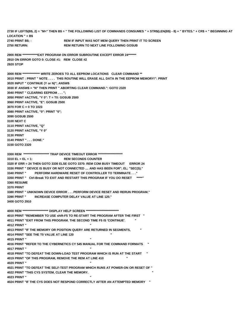
2730 IF LEFT$(B$, 2) = "M=" THEN B$ = " THE FOLLOWING LIST OF COMMANDS CONSUMES " + STR$(LEN(B$) - 8) + " BYTES." + CR$ + " BEGINNING AT
LOCATION " + B$
2740 PRINT B$; : REM IF INPUT WAS NOT MEM QUERY THEN PRINT IT TO SCREEN
2750 RETURN: REM RETURN TO NEXT LINE FOLLOWING GOSUB
2900 REM *************EXIT PROGRAM ON ERROR SUBROUTINE EXCEPT ERROR 24*******
2910 ON ERROR GOTO 0: CLOSE #1: REM CLOSE #2
2920 STOP
3000 REM *************** WRITE ZEROES TO ALL EEPROM LOCATIONS CLEAR COMMAND **
3010 PRINT : PRINT " NOTE . . . . THIS ROUTINE WILL ERASE ALL DATA IN THE EEPROM MEMORY!": PRINT
3020 INPUT " CONTINUE (Y or N)"; ANSW$
3030 IF ANSW$ = "N" THEN PRINT " ABORTING CLEAR COMMAND.": GOTO 2320
3040 PRINT " CLEARING EEPROM . . . ";
3050 PRINT #ACTIVE, "Y 0": T = T0: GOSUB 2500
3060 PRINT #ACTIVE, "E": GOSUB 2500
3070 FOR C = 0 TO 1023
3080 PRINT #ACTIVE, "0": PRINT "0";
3090 GOSUB 2500
3100 NEXT C
3110 PRINT #ACTIVE, "Q"
3120 PRINT #ACTIVE, "Y 0"
3130 PRINT
3140 PRINT " . . . DONE."
3150 GOTO 2320
3300 REM ********************** TRAP DEVICE TIMEOUT ERROR *********************
3310 EL = EL + 1: REM SECONDS COUNTER
3320 IF ERR = 24 THEN GOTO 3330 ELSE GOTO 3370: REM COM BUSY TIMEOUT ERROR 24
3330 PRINT " DEVICE IS BUSY OR NOT CONNECTED .... AND HAS BEEN FOR"; EL; "SEC(S)."
3340 PRINT " PERFORM HARDWARE RESET OF CONTROLLER TO TERMINATE . . ."
3350 PRINT " Ctrl-Break TO EXIT AND RESTART THIS PROGRAM IF YOU DO RESET *****"
3360 RESUME
3370 PRINT
3380 PRINT " UNKNOWN DEVICE ERROR . . . PERFORM DEVICE RESET AND RERUN PROGRAM."
3390 PRINT " INCREASE COMPUTER DELAY VALUE AT LINE 120."
3400 GOTO 2910
4000 REM ********************** DISPLAY HELP SCREEN ****************************
4010 PRINT "REMEMBER TO USE shift-F5 TO RE-START THE PROGRAM AFTER THE FIRST "
4011 PRINT "EXIT FROM THIS PROGRAM. THE SECOND TIME F5 IS 'CONTINUE'. "
4012 PRINT " "
4013 PRINT "IF THE MEMORY OR POSITION QUERY ARE RETURNED IN SEGMENTS, "
4014 PRINT "SEE THE T0 VALUE AT LINE 120 "
4015 PRINT " "
4016 PRINT "REFER TO THE CYBERNETICS CY 545 MANUAL FOR THE COMMAND FORMATS "
4017 PRINT " "
4018 PRINT "TO DEFEAT THE DOWN-LOAD TEST PROGRAM WHICH IS RUN AT THE START "
4019 PRINT "OF THIS PROGRAM, REMOVE THE REM AT LINE 410 "
4020 PRINT " "
4021 PRINT "TO DEFEAT THE SELF-TEST PROGRAM WHICH RUNS AT POWER-ON OR RESET OF "
4022 PRINT "THIS CYS SYSTEM, CLEAR THE MEMORY. "
4023 PRINT " "
4024 PRINT "IF THE CYS DOES NOT RESPOND CORRECTLY AFTER AN ATTEMPTED MEMORY "

4025 PRINT "LOAD, MOST OFTEN A FAULTY PROGRAM HAS BEEN LOADED AND THE SYSTEM "
4026 PRINT "IS TRAPPED IN A ENDLESS AUTO-START. SEE AUTO-START LOCKOUT PROCEDURE."
4027 PRINT " "
4028 PRINT " "
4029 PRINT "FOR MORE HELP: CALL THE SERVICE CENTER 800-424-STEP {415-969-5829} "
4030 GOTO 2010: REM RETURN TO ENTER COMMAND ROUTINE
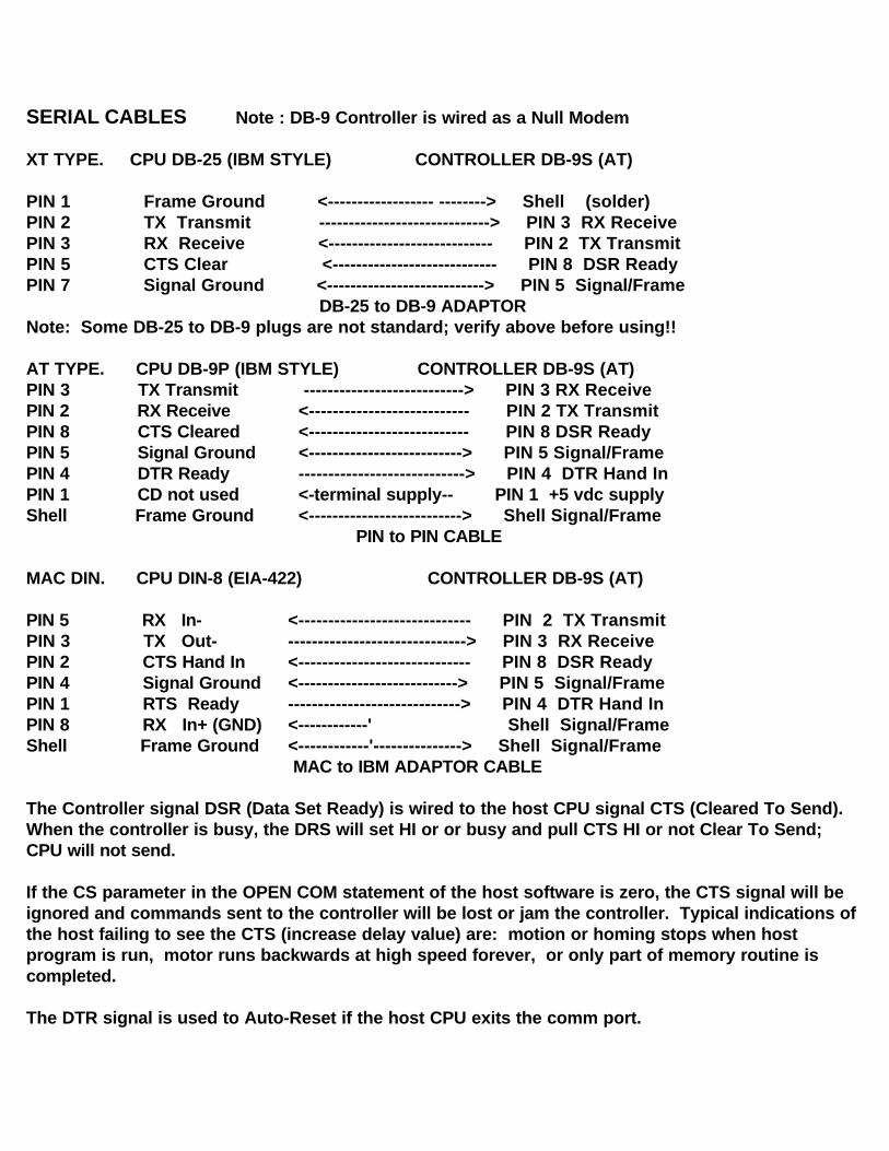
SERIAL CABLES Note : DB-9 Controller is wired as a Null Modem
XT TYPE. CPU DB-25 (IBM STYLE) CONTROLLER DB-9S (AT)
PIN 1 Frame Ground <------------------ --------> Shell (solder)PIN 2 TX Transmit -----------------------------> PIN 3 RX ReceivePIN 3 RX Receive <---------------------------- PIN 2 TX TransmitPIN 5 CTS Clear <---------------------------- PIN 8 DSR ReadyPIN 7 Signal Ground <---------------------------> PIN 5 Signal/Frame DB-25 to DB-9 ADAPTORNote: Some DB-25 to DB-9 plugs are not standard; verify above before using!!
AT TYPE. CPU DB-9P (IBM STYLE) CONTROLLER DB-9S (AT)PIN 3 TX Transmit ---------------------------> PIN 3 RX ReceivePIN 2 RX Receive <--------------------------- PIN 2 TX TransmitPIN 8 CTS Cleared <--------------------------- PIN 8 DSR ReadyPIN 5 Signal Ground <--------------------------> PIN 5 Signal/FramePIN 4 DTR Ready ----------------------------> PIN 4 DTR Hand InPIN 1 CD not used <-terminal supply-- PIN 1 +5 vdc supplyShell Frame Ground <--------------------------> Shell Signal/Frame PIN to PIN CABLE
MAC DIN. CPU DIN-8 (EIA-422) CONTROLLER DB-9S (AT)
PIN 5 RX In- <----------------------------- PIN 2 TX TransmitPIN 3 TX Out- ------------------------------> PIN 3 RX ReceivePIN 2 CTS Hand In <----------------------------- PIN 8 DSR ReadyPIN 4 Signal Ground <---------------------------> PIN 5 Signal/FramePIN 1 RTS Ready -----------------------------> PIN 4 DTR Hand InPIN 8 RX In+ (GND) <------------' Shell Signal/FrameShell Frame Ground <------------'---------------> Shell Signal/Frame MAC to IBM ADAPTOR CABLE
The Controller signal DSR (Data Set Ready) is wired to the host CPU signal CTS (Cleared To Send). When the controller is busy, the DRS will set HI or or busy and pull CTS HI or not Clear To Send; CPU will not send. If the CS parameter in the OPEN COM statement of the host software is zero, the CTS signal will be ignored and commands sent to the controller will be lost or jam the controller. Typical indications of the host failing to see the CTS (increase delay value) are: motion or homing stops when host program is run, motor runs backwards at high speed forever, or only part of memory routine is completed.
The DTR signal is used to Auto-Reset if the host CPU exits the comm port.

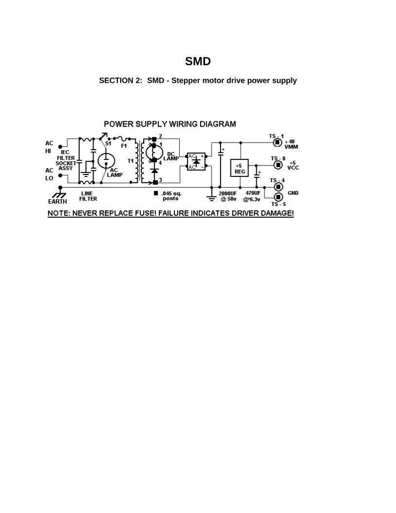
SMD
SECTION 2: SMD - Stepper motor drive power supply


PRODUCT DESCRIPTION. The MM & MS, Series 1 & 2, stepper motor driver, is a switching type, constant- current regulator which drives current pulses through the windings of a stepper motor. All stepper motors are stepped or rotated by changing the direction of the current flow through the windings in a unique sequence. Each change of current direction results in a step.
The driver contains two sections: (1) the step generator; and the (2) power drivers. The step generator is a digital logic system which receives input commands from a controller (typically a microprocessor) and generates a series of step signals. The power drivers receive the step signals and switch the phase of current in the motor windings.
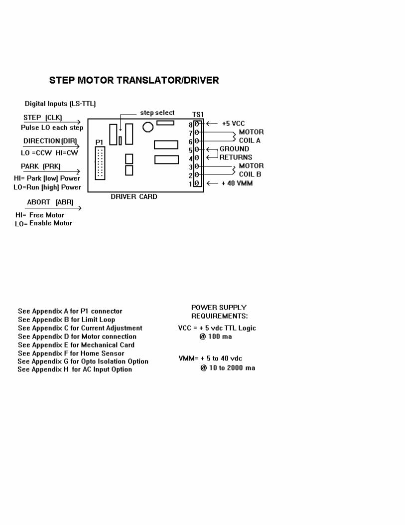
The driver requires a maximum of four input signals: (1) the step pulse - STP, (2) the direction level - DIR, (3) the power level - PRK, and the enable signal - ABR. The step pulse (or step clock) to the input of the driver will cause a corresponding change of the output current resulting in one step (one unit of motor rotation). The direction input is a digital level signal which controls the direction of motor rotation. If the signal is true (HIgh), the motor rotates in CW direction; if the signal is false (LOw), the motor rotates in CCW direction. In addition to the step and direction inputs, the driver will accept an output power control input. This digital input, PARK, controls the amount of current delivered to the motor windings either run power or park power. If the signal is HI or floating, the driver is at reduced current; if LO the driver is at full current. The enable signal, ABoRt, sets the current to either off or on. If the signal is HI or floating, the driver is FREE (no current); if LO, the driver is enabled.
In addition to the digital input signals, the driver also requires a power supply input of unregulated D.C. voltage. The driver functions to control the current furnished by the D.C. supply. The combination of a D.C. supply and the MS driver is referred to as a current-regulated power supply, or constant- current motor driver. The driver regulates the current through the motor winding by rapidly switching on and off the D.C. voltage. This technique is referred to as switch-mode or chopper stabilized regulation. The driver also requires +5 TTL logic supply for the digital sections.
STEP ANGLE. The drivers can be operated in three or four step angles: FULL-step or HALF- step, QUAD-step, and OCTAL-step only. In each of these modes, the output power control, PRK, is controlled by the CYS microprocessor or by on-driver control . PRK is used to reduce driver and motor heating during non-step periods.
THEORY OF OPERATION. The unique element in the driver is the current regulator device, referred to as the "driver chip". This driver has three main inputs: (1) the phase-control, F; (2) current-control, I0; (3) current-control, I1. The outputs of a driver are the connections to a single motor winding. Internally an output section contains four power transistors configured in an H-bridge with two pair sourcing current and two pair sinking current. The motor winding is connected across the bridge. If one source transistor (at one end of the winding) and one sink transistor (at the other end) are turned on, then current flows through the winding. Alternately, if the other pair is on, then the current will flow through the windings in the opposite direction. The D.C. Supply is connected to the top (positive) and bottom (negative) of th H-bridge transistor pairs. An external resistor (typically 1 ohm or less) is inserted in series between the negative of the H-bridge and the negative of the power supply negative so that the total winding current flows through the resistor. When full winding current flows, the small voltage across the resistor is fed back to the comparator section and turns off the H-bridge transistors. After a fixed-time off to allow the transistors to settle and the feed-back voltage to dissipate, the bridge again turns on and current builds up in the winding until the voltage across the sense-resistor again trips the comparator.
The digital phase-input (F) level (HI or LO) selects which pair turns on and corresponds to the direction of current flow through the winding. The current controls, (I0 and I1) select one of four comparators; zero, low, medium, or full. The output is therefore a series of current pulses equal in amplitude and separated by the period of fixed time off. The value ofthe current sense resistor is pre-selected to produce a current amplitude equal to that of the current rating of the motor winding. If I0 and I1 select a comparator other that FULL, then the sense resistor feed-back voltage trips at less than full current. The reference voltage of the comparators is also available as an input to the device. By externally controlling this reference input, the output current can be varied between zero and full (i.e. microstepping).
INSTALLATION AND OPERATION. Before operating the MS & MM series, that the input connections are correct for that mode. Refer to the installation wiring diagrams found in the back of this manual. Locations of jumpers and signals are identified on the bottom CYSe of the unit circuit board. The configuration of the driver requires attention to four areas: step size jumper, power supply voltage, motor winding connection, and current control dial-pot setting. Refer to driver label for maximum current and voltage limits of the particular model. Refer to the Appendix section in the rear of this manual for details.
(1) POWER SUPPLY & MOTOR CONNECTIONS Signal Name Terminal Strip TS1 Data Connector P1
VMM TS1-1 noneIn general, the driver requires an unregulated source of D.C. voltage connected to VMM. The current output must equal 1.414 the full rating of one motor winding. The voltage can be between 12 and 45 volts D.C. (maximum). The higher voltage is required only for higher step rates. In general, do not use a regulated power supply as performance is reduced. Refer to the unit label for the VMM maximum of that model.
VCC TS1-8 P1-13 & 14, 1, 6If the optional +5vdc TTL supply is not installed, then an external 150ma digital supply is connected to the TS1-8 VCC connections. TS1-5 is provided for ground return. TS1-8 is protected by a 6.8vdc TRANSORB. The VCC is ALSO common through the digital control connector P1-13 & 14. The +5vdc can be furnished by: (1) the computer or controller power supply only, or both. If the system power is not controlled by one switch, always isolate the driver systems with a diode in the VCC connection. In any case, controller VCC and driver VCC MUST BE COMMON or other interface connections are required (opto isolation).
GND TS1-4 & 5 P1-19, 3, 5In all cases, ground is COMMON to all grounds; digital VCC, analog VMM, chassis ground and green wire ground (AC power ground). If a dual (VMM & VCC) supply is used, then an identical and equal ground lead is connected; 2 each wires to TS1-4 and 5. Always bridge the supply returns and connect to chassis. If separate supplies are used, connect the VMM supply and ground to the TS1 connector. Connect the driver VCC (P1-13&14) and ground (P1-19) from the driver to the controller bus. Connect the VCC supply to the controller bus. IN ALL CASES, ANY VCC BETWEEN THE CONTROLLER AND IN THE DRIVER MUST BE COMMON OR ELSE OPTICAL ISOLATION IS REQUIRED. In all cases, connect chassis ground (green wire ground or earth) to the driver or supply grounds.
COIL-A/COIL-B TS1-2 & 3, TS1-6 & 7 noneA pair of motor windings are connected across each coil connection. Bipolar motors have FOUR leads (two pair). Unipolar motors with SIX leads can be used provided a coil end and a center tap are connected (unused wires MUST be INSULATED and cut off or tied back). NEVER attempt to connect the center taps of unipolar motors to VMM, except in the case of FIVE wire motors . NEVER insert dropping resistors in the power supply leads or winding leads. NEVER insert caps or coil filters across the windings.
(2) INPUT SIGNALS Digital Inputs P1-12/20 & 11/19 See Appendix A
Step Input (CLK) P1- 15The step-clock (+5vdc TTL compatible) inputs to the clock pin of the driver translator. The driver logic toggles on a LO to HI transition. The Step CLK MUST be normally HI (+5vdc) and go LO only long enough to toggle th counter (100us to 1ms). Refer to TTL data books for max/min clock conditions. A pull-up resistor (4.7k) is installed on the step clock input.
Direction Input (DIR) P1- 17The direction level inputs to the driver translator. The input is pulled up by a 4.7k resistor. Setting the input HI or LO reverses the direction of motor rotation. Motor rotation with respect to the state of the direction input may be reversed by reversing the motor winding pairs.
Current Control Input (PRK) P1- 11The current control signal, if required, shifts the output current to the motor coils between 100% power and park power. When PRK is LO (0vdc), the unit produces FULL power. If PRK is HI (+5vdc) or floating, the units outputs at PARK power. On units so equipped, PARK power may be preset at the medium (MED) power level. PARK condition is used to reduce power supply requirements and motor dissipation during non-step periods. Any load which can be moved by the motor at full power can be firmly PARKed at low power. The motor will free-wheel only if the ABORT (ABR) line is HI.
Abort Control Input (ABR) P1- 9 (see next)The ABR input must be LO to step. If the input is HI or disconnected, the driver control output will output zero current. NOTE: the driver is not OFF, power is still being regulated to the zero condition. The motor will free-wheel. ABORT is normally only used in stand-by (position loss may occur), in series with safety switches (limits) or other emergency stop conditions.
Other Signals (CPU ABR and HOME) P1- 10,12 & P1- 4,16 Pin 12 is the normal input to P1-9 when the ABoRt Loop is used. Pin 4, 16 is the output signal HOME back to the controlling device.

Spare Inputs P1- 18, 8 & P1- 20, 7Pins 18 and 20 can be used for other signals to/from the card. See Chassis Signals connector. Pin 20 is normally keyed on free standing cards.
(3) Chassis Signals P1- 1 to 9 & P1- 2 to 10These signals are normally used to provide for a convenient method of cabling the driver between the controller and the motor, power supply, chassis assemblies.
Home Sensor Pins P1- 1, 2, 3, 4These pins power the optical home sensor circuit. SEE APPENDIX A & F. Pin 1 is VCC +5 power, pin 2 is VLED power, pin 3 is GND (ground), and pin 4 is the HOME input from the sensor. Abort Loop Pins P1- 9 & P1- 10/12These pins normally constitute the ABoRt Loop Safety (limits) System. The driver enable is output from the controller to pin 12 (CPU ABR) and output to the loop from pin 10 (to limit loop) and returned from the loop to pin 9 (ABR). The ABR loop is NORMALLY CLOSED; opening the loop for any reason FREEs the motors. Never connect these signals to any potential or device except passive switches or relays. Door locks and other safety switches may be inserted in the loop. See Appendix B.
Spare Pins P1- 6, 5, 7, 8These pins are used as required to provide VCC (pin 6) and GND (pin 5) to the chassis system. Pins 7 and 8 are user pins which are generally jumped as required to the spare pins on the data connector. See Appendix A.
(4) FULL/HALF/QUARTER/OCTAL STEP SELECT Typically, the step angle is set with dip-clip jumpers. The jumper pins are located on the top of the card. refer to the driver card wiring diagram.
(5) CURRENT CONTROL DIAL The current dial sets the 100% power level of the driver outputs as required. Refer to App C.

APPENDIX SECTION
APPENDIX B: DESCRIPTION OF HOMING AND ABORT LOOP PAGE 1/2
HOMING. A major advantage of a digital Open-Loop step system is the ability to operate plus or minus zero steps (no error). Two conditions are required. One is that the motor is sufficient for the load in normal operation and second, that a reference position, commonly called the "home position", be consistently established during initialization of the system. When step motors are rotated by counting (clocking) out a number of steps, in theory, the motion will take place +/- zero steps. The exact mechanical position of the motor can vary by the motor step accuracy; typically +/- 3 % of one step (non-cumlative). A proof of +/- zero step operation is, first, to reference a starting positon of the motor or "home". During homing, the motor is stepped backwards into a switch, reversed, and then stepped forward until the switch opens. The point of interest is not the exact mechanical position but rather on which step the switch changed state. For that reason, only high resolution "PHOTO-LOGIC" optical-beam switches are used in TMG systems.
SLIP-DETECTION. After the motor is home, the controller position counter is reset to the home position, typically position1 (one step out of the sensor). The motor is then stepped CW to any position. To slip-detect the system, the motor is returned to position 1. If the sensor remains open, then the motor is stepped to positon 0. If the sensor closes, the system is operating +/- zero steps (error free). Note that a single step lost (slip) will always result in at least a movement of 4 full steps away from the correct position. Open loop systems are slip-detected at regular intervals to prove continuing slip-free operation.
CENTER HOME AND CONTIGUOUS SLIP DETECTION. If the home sensor is located at the center of axis motion and a step bar is mounted along the entire motion path, then the home position can be verified each time the system crosses the center line. A stepped bar is thin strip with a left high CYSe and a right low CYSe. The high to low edge is the center line. LASH COMPENSATION. A major advantage of steppers is in their "repeatability" which is typically less than .01 % because the digital controls are not affected by temperature, aging, voltage or adjustment. This allows errors such as lash and distortion to be zeroed-out.
Lash compensation adds or subtracts steps, at each change of direction or because of other forces, to take-up the lash error. Lash compensation is accomplished during the slip-detection process. When the system is slip-detected the first time, the sensor will not close at position 0 because of the lash; home LED remains off. At this point, the system is single-stepped CCW until the sensor closes; home LED is on. The number of CCW steps is the lash compensation value. The system is re-homed and the counter loaded with this value (see At home command). The motor is then moved some number of steps CW, returned to position 1 (sensor open), and finally position 0 (sensor closed). The system is +/- zero steps.
Screw distortion error occurs when the screw pitch, which is so many turns per inch, does not move the correct distance after the correct number of turns of the motor. For example, a 10 turn screw should cause linear travel of 1 inch every 2000 steps (200 step/rev motor). If, rather than commanding the motor controller to go in 2000 step increments, the controller moves to absolute positions such as 2000, 4001, 6003, 7999, ect.; the error is eliminated. This technique requires a control system which carries a "map" with each individual machine. The EEPROM memory is suitable for this purpose.
APPENDIX B: DESCRIPTION OF HOMING AND ABORT LOOP PAGE 2/2
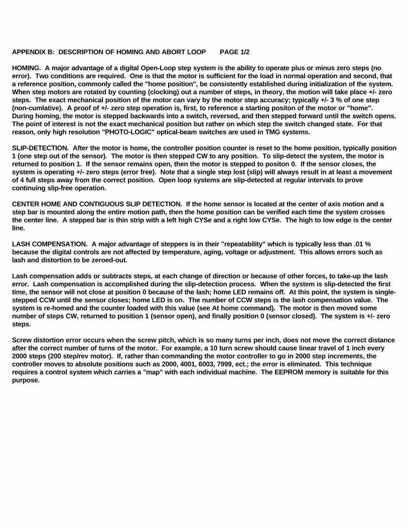
SUPER HOMING. In high resolution systems, two sensors are used. The first sensor, the home sensor, is mounted to themotion platform in the typical configuration. The second sensor, the index sensor, is located as an index detector on the motor shaft. The index can be either a disk with a tab or a long pin. During the homing operation, the motor is stepped backwards until the first sensor is blocked. The motor, however, continues to rotate until the second or index mark is detected. The system is now "homed to the step". TMG systems with Super-Homing use two identical "PHOTO-LOGIC" sensors wire-ORed together so that both must be blocked before the home signal is detected. The H or home command of the motion controller will operate with either single or double sensors.
ABORT LOOP FUNCTION. In TMG systems, the ABORT loop is used to remove all winding power to the motor during an out-of-bounds condition. The ABORT feature can be used to provide hard-limits, emergency stop, door inter-locks, and other safety features. As the ABR input, to the driver, must be LO (ground) for the driver to step; opening the loop will stop (free) the motor regardless of the control logic. The diagram is typical of TMG "Fail-Safe, Hard-Soft" limit loops.
NOTE: CONTRARY TO POPULAR PRACTICE, IT IS UNWISE AND UNSAFE TO SENSE LIMITS AND OTHER SAFETY CONDITIONS THROUGH THE COMPUTER INPUTS PORTS.
All motion products, regardless of their final intended form, should initially incorporate home sensors and slip-detection in order to prove correct positioning during product development, particularly during software de-bugging. Typically, a test routine is established which passes slip-detection. Any detrimental modification or code flaw will be flagged by this routine.
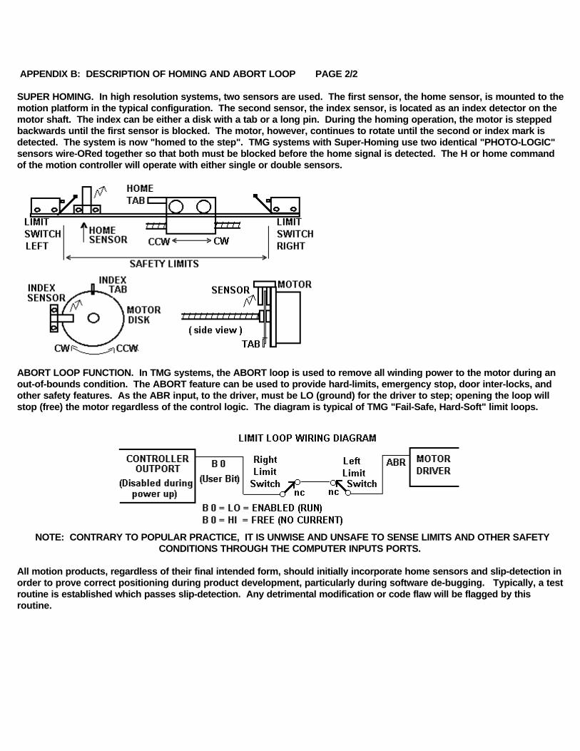
APPENDIX C TYPICAL MOTOR CURRENT ADJUST PAGE 1/1

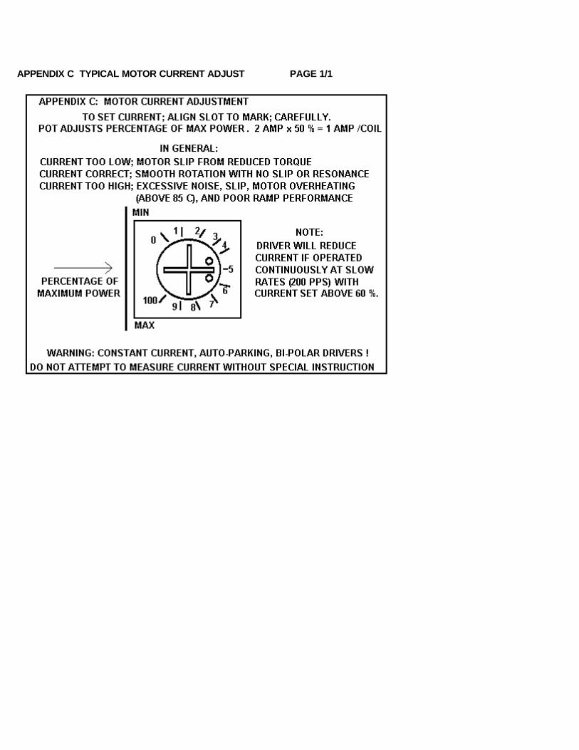
APPENDIX D MOTOR WIRING SCHEMES PAGE 1/2
Performance of a stepper motor based system depends more on the electronic drivers used than it does on the motor itself. A step motor (both PM and
Hybrid type) is made to step by sequencing the orientations of the magnetic fields in two coils. The UNIPOLAR drive method of is illustrated, in the
figure, using just ONE coil of the motor. Note that the center tap of the coil is connected to the positive motor supply voltage. An electronic circuit,
represented by the switch, then connects one end or the other to ground for current to flow from the center tap to the grounded end. The most
significant factor is that only one-half of the coil is used at any given time and that the magnetic field intensity (motor torque) is proportional to the
product of the number of turns in the coil and the current passing through the coil.
Motors designed for BIPOLAR drivers will often have only four leads. However some manufactures will provide the motors in 8 wire versions to offer a
performance choice for bipolar drive users as in figures C & D. Four lead bipolar motors may use larger wire, since only half the windings are required
in the given space of the motor body. The paralleling in figure C is the equivalent of this to achieve lower winding resistance and thereby doubling
motor efficiency. The other alternative for the motor designers is to use a greater number of turns in the winding space. This is shown by figures B & D
and results in more torque with a lower coil current but a subsequent loss of high speed torque.
Although step motors are often classified as bipolar or unipolar (2 phase or 4 phase), these terms are more accurately applied to the types of electronic
circuit used to drive the motor. Bipolar drivers can drive 4,5,6 and 8 wire motors. When the motor is described as unipolar, the specifications are
presented with the assumption that the motor will be driven with a unipolar drive. Therefore the specifications must be translated to bipolar when the
motor is used with a bipolar driver. In general, the translation is similar to a unipolar driver with dropping resistors in series with the center taps;
referred to as L over x R with R equal to the motor winding resistance. For example, a L over 4R unipolar driver has a resistor equal to 4 times the
winding resistance. In bipolar, the L over R ratio is the ratio of the motor voltage to the supply voltage. A L over 4R bipolar drive, for example, would
be a 6 volt motor and a 24 volt power supply. Performance would be similar to the L/4R torque curve of a unipolar motor. The figures identify the
various connection options when using a bipolar driver with 6 or 8 wire motors.
A: SINGLE COILS. Identical to unipolar specification (if the supply voltage equals the specified motor voltage). Normal connection of a bipolar driver
to 6 wire motor.
B & D: SERIES COILS. This configuration will produce torque greater than the unipolar specification indicates. To stay within the power (wattage)
rating of the motor, reduce the unipolar specified current by 30%; depending on the duty-cycle of the system (park time). Note that the torque curve of
this configuration is conCYSerably fore-shortened as this motor is now the same as a motor with a rating of twice the voltage (slower motor).
C: PARALLEL COILS. When this configuration is driven at the unipolar current, the motor will perform identical to the specification but the motor will
dissipate only one-half the power (it is twice as efficient). When the current is increased by 1.414, to drive the motor at it"s full power rating, the motor
torque is increased by approximately 60% Note that this torque curve is extended by four times (high speed system).
Resonance (vibration) of a step motion system depends on the speed and power range of the motor. Fast windings (A & C) are "quicker" and may
break into resonance easier than slow (B & D). Power windings (B & D) may deliver "excessive" power (torque) to the system and produce resonance.
In general, resonance indicates, except at the low (100 sps) and mid-frequency (1000 sps) bands, excessive power; therefore reduce the driver current
for smoother operation or wire the motor for "softer" response.
NOTES: If a motor runs "backwards" with respect to software direction, transpose the connections of ONE coil. For MS series driver cards, pins 2 & 3 or
6 & 7; CYS / SMD driver boxes, pins 1 & 3 or $ & 6.
Five wire motors are really 6 wire motors with the center tap common. The center tap must be connected to the motor supply voltage. If phases 1, 2,
3 or 4 are crossed, motor will not rotate (hums). For MS cards, pin 1 is VMM, for CYS /SMD (if connected), pin 5 is VMM and pin 2 is GND.
Systems with pin 5 & 2 connected are used to power external relays or solinoid valves. The pins are keyed (reversed). Never attempt to connect any
motor leads to pin 2 and only 5 wire center taps to pin 5. Pins 2 & 5 are normally not connected and used to store the unused leads of 6 or 8 wire
motors.

APPENDIX I PAGE 1/1
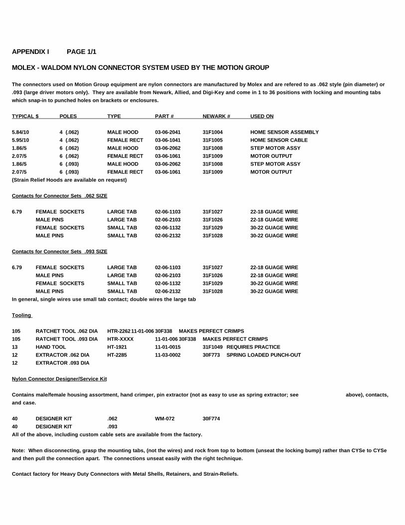
MOLEX - WALDOM NYLON CONNECTOR SYSTEM USED BY THE MOTION GROUP
The connectors used on Motion Group equipment are nylon connectors are manufactured by Molex and are refered to as .062 style (pin diameter) or
.093 (large driver motors only). They are available from Newark, Allied, and Digi-Key and come in 1 to 36 positions with locking and mounting tabs
which snap-in to punched holes on brackets or enclosures.
TYPICAL $ POLES TYPE PART # NEWARK # USED ON
5.84/10 4 (.062) MALE HOOD 03-06-2041 31F1004 HOME SENSOR ASSEMBLY
5.95/10 4 (.062) FEMALE RECT 03-06-1041 31F1005 HOME SENSOR CABLE
1.86/5 6 (.062) MALE HOOD 03-06-2062 31F1008 STEP MOTOR ASSY
2.07/5 6 (.062) FEMALE RECT 03-06-1061 31F1009 MOTOR OUTPUT
1.86/5 6 (.093) MALE HOOD 03-06-2062 31F1008 STEP MOTOR ASSY
2.07/5 6 (.093) FEMALE RECT 03-06-1061 31F1009 MOTOR OUTPUT
(Strain Relief Hoods are available on request)
Contacts for Connector Sets .062 SIZE
6.79 FEMALE SOCKETS LARGE TAB 02-06-1103 31F1027 22-18 GUAGE WIRE
MALE PINS LARGE TAB 02-06-2103 31F1026 22-18 GUAGE WIRE
FEMALE SOCKETS SMALL TAB 02-06-1132 31F1029 30-22 GUAGE WIRE
MALE PINS SMALL TAB 02-06-2132 31F1028 30-22 GUAGE WIRE
Contacts for Connector Sets .093 SIZE
6.79 FEMALE SOCKETS LARGE TAB 02-06-1103 31F1027 22-18 GUAGE WIRE
MALE PINS LARGE TAB 02-06-2103 31F1026 22-18 GUAGE WIRE
FEMALE SOCKETS SMALL TAB 02-06-1132 31F1029 30-22 GUAGE WIRE
MALE PINS SMALL TAB 02-06-2132 31F1028 30-22 GUAGE WIRE
In general, single wires use small tab contact; double wires the large tab
Tooling
105 RATCHET TOOL .062 DIA HTR-226211-01-006 30F338 MAKES PERFECT CRIMPS
105 RATCHET TOOL .093 DIA HTR-XXXX 11-01-006 30F338 MAKES PERFECT CRIMPS
13 HAND TOOL HT-1921 11-01-0015 31F1049 REQUIRES PRACTICE
12 EXTRACTOR .062 DIA HT-2285 11-03-0002 30F773 SPRING LOADED PUNCH-OUT
12 EXTRACTOR .093 DIA
Nylon Connector Designer/Service Kit
Contains male/female housing assortment, hand crimper, pin extractor (not as easy to use as spring extractor; see above), contacts,
and case.
40 DESIGNER KIT .062 WM-072 30F774
40 DESIGNER KIT .093
All of the above, including custom cable sets are available from the factory.
Note: When disconnecting, grasp the mounting tabs, (not the wires) and rock from top to bottom (unseat the locking bump) rather than CYSe to CYSe
and then pull the connection apart. The connections unseat easily with the right technique.
Contact factory for Heavy Duty Connectors with Metal Shells, Retainers, and Strain-Reliefs.
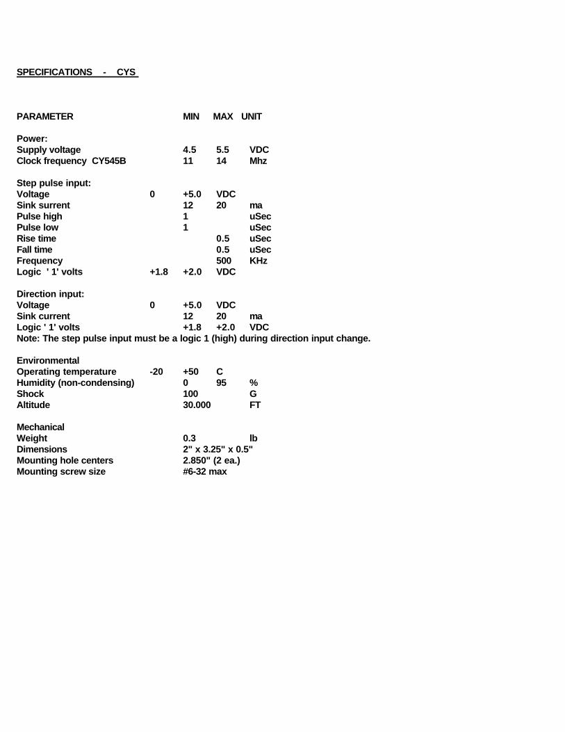
SPECIFICATIONS - CYS
PARAMETER MIN MAX UNIT
Power: Supply voltage 4.5 5.5 VDCClock frequency CY545B 11 14 Mhz
Step pulse input: Voltage 0 +5.0 VDCSink surrent 12 20 maPulse high 1 uSecPulse low 1 uSecRise time 0.5 uSecFall time 0.5 uSecFrequency 500 KHzLogic ' 1' volts +1.8 +2.0 VDC
Direction input: Voltage 0 +5.0 VDCSink current 12 20 maLogic ' 1' volts +1.8 +2.0 VDCNote: The step pulse input must be a logic 1 (high) during direction input change.
EnvironmentalOperating temperature -20 +50 CHumidity (non-condensing) 0 95 %Shock 100 GAltitude 30.000 FT
MechanicalWeight 0.3 lbDimensions 2" x 3.25" x 0.5"Mounting hole centers 2.850" (2 ea.)Mounting screw size #6-32 max


![Modèles structuraux et fonctionnels du site actif des … · 2014. 10. 4. · Ni Cys-S S S Cys-S Fe CN CN CO Cys Cys Site actif des H2ases [NiFe] Dérivés du [Ni(xbsms)]: 1. Synthèse](https://img.pdfslide.net/doc/110x75/5fc526ed9695db7c55538df1/modles-structuraux-et-fonctionnels-du-site-actif-des-2014-10-4-ni-cys-s-s.jpg)