Embed Size (px)
Citation preview

CyWi: An Open-Source Wireless Innovation
Lab for SmartAg, AR/VR, and Beyond
Design Document
Chenye Lim
Jian Chew
Pawel Darowski
Ryan Cullinan
Shay Willems
Tyler Beder
SD-DEC19-02
May 2019

1. Frontal Material
1.1 Table of Contents
1. Frontal Material 1
1.1 Table of Contents 1
1.2 List of Figures 2
1.3 List of Tables 2
2. Introductory Material 3
2.1 Problem Statement 3
2.2 Operating Environment 4
2.3 Intended Users and Intended Uses 4
2.4 Assumptions and Limitations 5
2.4.1 Assumptions 5
2.4.2 Limitations 5
2.5 Expected End Product and Deliverables 6
2.6 Related Work / Literature Review 6
2.7 Acknowledgements 6
3. Specifications and Analysis 7
3.1 Proposed Design 7
3.2 Design Analysis 9
4. Testing and Implementation 11
4.1 Interface Specifications 11
4.2 Hardware and Software 12
4.3 Process 12
4.4 Functional Testing 12
4.5 Non-Functional Testing 13
4.6 Results 14
5. Closure Material 15
5.1 Conclusion 15
5.2 References 15
5.3 Appendices 16
5.3.1 Intel NUC Comparison Chart 16
5.3.2 Intel NUC Comparison Graph 17
1

1.2 List of Figures Figure 1: Use Case Diagrams 3
Figure 2: Bandwidth to Latency Relations 5
Figure 3: High Level Block Diagram 7
1.3 List of Tables Table 1: Major Tasks with Description and Estimated Hours 15-17
Table 2: Expected Cost of the Project 17-18
Table 3: Project Checkpoints with Descriptions and Estimated Deadlines 18-20
2

2. Introductory Material
2.1 Problem Statement
Over the last decade, the experimentation of the Cyber-Physical Systems (CPS) and Internet of
Things (IoT) has been in full force because of the multitude of advantages it can bring to
everyday life. Despite many years of research, we are still at the infancy of IoT and Industry 4.0
capabilities. IoT can be used for a wide range of products such as SmartAg, connected
autonomous vehicles, smart grids, and AR/VR. Powered with the capabilities of 5G, IoT
promises to change every aspect of our lives. But to continue with this pace of innovation,
researchers need space to run experiments and gather real-world data.
Figure 1: Use Case Diagrams
3

Iowa State University has decided to explore this field with the development of the CyWi lab.
This lab will consist of a multi-node testbed located on the Iowa State campus and will be
available to researchers and testers to run their experimentation code. This lab will feature the
most bleeding-edge wireless innovation platforms as well as emerging wireless solutions. It will
also feature 5G wireless for new learning, teaching, and researching across the globe.
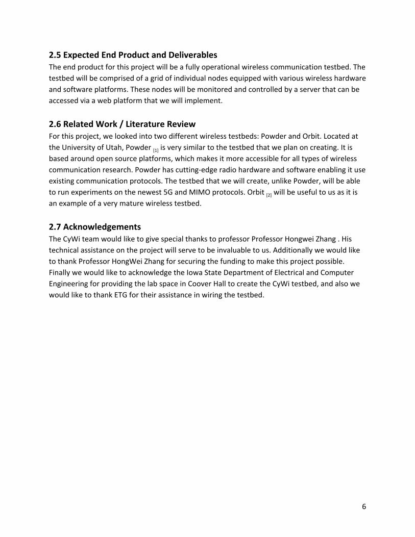
2.2 Operating Environment The CyWi’s testbed will be located in 3050 Coover Hall at Iowa State University (ISU). This is a
climate-controlled room with a keycard secured door. The only people allowed into the lab
room are those with keycards: the professor/client, the ISU Electronics Technology Group
(ETG), and a handful of researchers. Users will access the testbed via the remote web interface,
never via physical access to the lab. One wall has windows facing west but the blinds will be
closed so sunshine never touches the equipment. While it is not expected for the hardware to
experience anything but optimal operating conditions, our web-based service will be exposed
to the Internet so cyber attacks, such as DDoS, are possible.
2.3 Intended Users and Intended Uses The CyWi testbed is intended for two general types of users: students and researchers.
Students learn about wireless signals and protocols in their courses via lectures, assignments,
and small projects. Theoretical knowledge is crucial. However, building upon that foundation
with extensive lab experience configuring real-world hardware will improve students’
understanding of the subject matter. Implementing wireless topologies such as mesh, star, and
point-to-point could inspire future IoT developers. Comparing Zigbee and Bluetooth Low Energy
performance, for example, over assorted ranges, signal strengths, and conditions will extend
students’ knowledge of technology strengths and limitations. CyWi will provide students the
opportunity to experiment with a variety of popular, existing wireless technologies and to
expand their understanding in a safe environment.
Researchers, on the other hand, will appreciate the cutting-edge communication technologies
represented by the CyWi testbed. Access to powerful and configurable software-defined radios
(SDRs) will allow researchers to study a wide spectrum of new heterogeneous networks and
explore exciting innovative ideas. Researchers will evaluate performance monitoring and
statistics after each experiment to determine feasibility of their chosen path. Emerging
technologies such as 5G, SmartAg, augmented reality, virtual reality, and Internet-of-Things will
generate opportunities for decades of continuous communications development. As Figure 2
shows, CyWi is particularly equipped to handle experiments of various throughput and latency
specifications.
4

Figure 2: Bandwidth to Latency Relations
2.4 Assumptions and Limitations 2.4.1 Assumptions
● Environmental conditions in the lab room will remain nominal for electronics.
● Internet access will be sufficient and reliable.
● Outside wireless signal interference will be negligible.
● Users will be students and researchers so they will be somewhat familiar with testbeds.
● Users will participate in reporting bugs if or when they arise for continued
improvement.
● ISU Electrical and Computer Engineering department will publish or advertise that this
testbed is ready for students and researchers to use.
2.4.2 Limitations
● All software used must be open-source.
● Lab room has space for only 110 total nodes.
● Budget is a factor so the amount of SDRs is limited.
● Two semesters is the maximum time to spend designing and developing this project.
● Some elements of this project are new to us so time will need to be spend researching.
5
2.5 Expected End Product and Deliverables The end product for this project will be a fully operational wireless communication testbed. The
testbed will be comprised of a grid of individual nodes equipped with various wireless hardware
and software platforms. These nodes will be monitored and controlled by a server that can be
accessed via a web platform that we will implement.
2.6 Related Work / Literature Review For this project, we looked into two different wireless testbeds: Powder and Orbit. Located at
the University of Utah, Powder [1] is very similar to the testbed that we plan on creating. It is
based around open source platforms, which makes it more accessible for all types of wireless
communication research. Powder has cutting-edge radio hardware and software enabling it use
existing communication protocols. The testbed that we will create, unlike Powder, will be able
to run experiments on the newest 5G and MIMO protocols. Orbit [2] will be useful to us as it is
an example of a very mature wireless testbed.
2.7 Acknowledgements The CyWi team would like to give special thanks to professor Professor Hongwei Zhang . His
technical assistance on the project will serve to be invaluable to us. Additionally we would like
to thank Professor HongWei Zhang for securing the funding to make this project possible.
Finally we would like to acknowledge the Iowa State Department of Electrical and Computer
Engineering for providing the lab space in Coover Hall to create the CyWi testbed, and also we
would like to thank ETG for their assistance in wiring the testbed.
6

3. Specifications and Analysis
3.1 Proposed Design
Figure 3: High Level Block Diagram
7

Our testbed design features two separate sets of wireless devices: software-defined radio (SDR)
nodes and CPS (cyber-physical system) motes. Both sets of nodes are mounted to a 11x10 grid
of square ceiling tiles -- each tile measuring two feet in width and length. To facilitate remote
configuring of the nodes, USB cables connect each node to one of two node controllers via
intermediate USB hubs. The node controllers are then connected to a networking switch via
Ethernet cables and ultimately to our Internet-connected server.
SDR nodes account for a majority of the project budget so at the moment we are limited to
three SDRs which will be sufficient to run interesting 5G experiments. We have settled on the
Ettus USRP X310 [4] platform due to its flexibility, reliability, and compatibility with the
OpenAirInterface framework. These SDRs are capable of generating, transmitting, and receiving
signals at up to 6 GHz. OpenAirInterface [7] is a framework that provides software and tools to
research 5G radio access networks.
CPS motes are fairly inexpensive so we’ve purchased and mounted 20 Texas Instruments
LAUNCHXL-CC26X2R1 [6] development kits. These devices are capable of implementing multiple
wireless protocols including Wi-Fi, Bluetooth Low Energy, and IEEE 802.15.4 standard protocols
such as Thread, Zigbee, and Sub-1 GHz. The development kits feature a CC2642R MCU which
includes a powerful ARM Cortex-M4F CPU, 352 KB of flash memory, and 80 KB of RAM. A
dedicated low-power ARM Cortex-M0 processes RF signals to maximize energy efficiency.
These development kits support TI-RTOS (an open-source real time operating system under a
BSD-like license) and implement the SimpleLink SDK platform which provides well-documented
hardware drivers and stacks. During our search for suitable CPS motes, we compared this Texas
Instruments development kit with others developed by Qualcomm, NXP, and Nordic but none
of those were able to offer a powerful MCU, open documentation, and community support at
the right price.
Two node controllers were installed on the ceiling tile grid to provide access to our SDR and CPS
motes. Node controllers are mini PCs running Linux/GNU that provide configuration and
communication to the nodes. The SDR nodes, in particular, need powerful node controllers to
implement their software radio components. For this task, we chose the Intel NUC8
(NUC8i7BEH) mini PC [3] with a powerful i7-8559U CPU and supporting up to 32 GB of RAM. We
carefully analyzed a variety of NUC7 and NUC8 mini PCs as well as the cheaper yet much less
powerful MintBox. A comparison chart and graph can be found in Appendix 5.3.1 and 5.3.2.
Eventually we settled on the NUC8i7BEH due to its high computational ability and comfortable
price point, thanks in part to a less impressive GPU.
Finally, the server machine will host a multitude of open-source software designed to allow
remote access, manage resources, store data, and interact with the node controllers. We plan
8

on repurposing as much freely-available software as we can find but inevitably we will need to
write our own programs. The node configuration manager software that communicates with
node controllers and individual nodes will certainly have to be developed in-house. Services
such as a web server, FTP server, SSH server, and database will need careful configuration to
with the rest of our systems.
The CyWi Innovation Lab will satisfy the following functional and non-functional requirements:
Functional Requirements
● System must register users and assign individual accounts
● Resource slices (time period, nodes, etc) will be reservable
● Resource scheduler must efficiently allocate node resources based on reserved slices
● Experiment scripts will be customizable by the users
● Experiments must be run remotely via web server
● Users will have the ability to export experiment results
Non-Functional Requirements
● System must remain available outside of maintenance hours
● System must implement robust state-machine for crash resilience
● Databases will be backed up on a regular basis
● System status and performance will be tracked and available for users
● Only registered users will be allowed to access the system
● All software will be open-source
● User experience must be responsive
The CyWi Innovation Lab works in accordance with several standards including:
● Ethernet (IEEE 802.3)
● Wi-Fi (IEEE 802.11)
● Bluetooth (IEEE 802.15)
● Thread, Zigbee, and Sub-1 GHz (IEEE 802.15.4)
3.2 Design Analysis To date, we have largely focused on defining what a wireless testbed should be. Existing
testbeds such as Powder and Orbit have helped us piece together how CyWi should function.
Gaining access to Powder and Orbit took longer than we had hoped but eventually we were
able to perform some tutorial experiments. These testbeds are already well-established and
have a diverse environment of devices.
9

At the start of the project, our goal was to have 110 CPS motes and 20 SDRs but the initial
funding was not as rich as we had hoped. We had to scale back to 20 CPS motes and 3 SDRs for
the time being. Investors are keen on viewing what we have planned so far so we are hopeful
that more cash flow will soon be made available. On top of that, we decided to lower our risk
by not ordering over $80,000 worth of equipment until we can ensure the smaller unit system
is feasible. Since we currently have at least one of each unit, adding more quantity of each
device (additional 90 CPS motes and 17 SDRs) is simply duplicating what we currently have.
Whether we have 20 or 110 motes, the server-side of the system will remain mostly the same.
Every single server component (such as SSH, FTP, Node Configuration Manager, Access Control,
etc) will need to be implemented regardless of node quantity. In fact, it will be easier to test
each subsystem if we only have to focus on a couple devices at one time. We will have
sufficient nodes to provide a proof-of-concept for the project. As we add more devices next
semester, the main difference in operations will be verifying that multiple Node Controllers
work together well. Some server components, such as the Resource Scheduler, will be busier so
our focus will be on how adding nodes will affect server performance and user experience.
We have selected all of the testbed hardware. These choices are based on our solid research
spanning many vendors and products. For our CPS motes, we selected the TI
LAUNCHXL-CC26X2R1 [6] development kits. This TI development board supports many open
source software and offers excellent documentation, both of which will allow our testbed to be
more accessible. The next piece of hardware that we picked was the node controller. Our node
controllers are mini PCs, specifically Intel NUC8s. Size is a factor because these PCs need to be
mounted above the ceiling tile, but the PCs also need to be powerful enough to run several
wireless devices at a time and SDRs are resource-demanding. The decision to go with the
NUC8i7BEH [3] was based primarily on its high performance but this was balanced with its price.
After determining that the tasks these node controllers will be performing were going to be
more CPU than GPU intensive, we placed more weight on the cost-to-performance ratio of the
CPU rather than the GPU. We compared this CPU ratio across six different Intel NUC models
and concluded that the NUC8i7BEH was the best choice for our application.
Overall, we are pleased with our hardware choices. We feel that a major strength of our
decision process has been selecting our node controllers. The model we decided on after
conducting research is both significantly cheaper and higher in performance than the NUC our
client had originally suggested. One weakness of the project so far has been that we
underestimated just how much time will be spent researching. The hardware selection process
may be complete but we will continue to spends many, many hours reading documentation and
bringing the technologies to life.
10
4. Testing and Implementation
4.1 Interface Specifications To fully test our system, we have to look at each component to determine how it interfaces
with the others. We can begin by defining the interfaces between our four types of physical
hardware: CPS motes, SDR nodes, Node Controllers, and server. Then we can define the
interfaces of our various services: web server, SSH server, FTP server, SQL database, access
control system, resource scheduler, and node configuration manager.
The physical connections are as follows. The server connects to an Ethernet switch in the lab
room with Cat5 cable. Each of the Node Controllers also have an Ethernet connection to the
switch. All the Node Controllers and the server will be on the same VLAN as we have no need
for more complicated switching or routing. Up to ten CPS motes will connect to one Node
Controller via USB cables and a USB hub.
Since the CPS motes run with an operating system and are able to communicate wirelessly,
they are not as reliant on host PCs as the SDR nodes are. In fact, the Node Controller will be
transparent to the user in regards to using CPS motes. Researchers will use software provided
by Emulab [8] to upload custom disk images to the Node Controllers, which will automatically
push them to each CPS mote along with any other specified configurations. Configurations are
completely up to the experiment owner but could include initial RF signal power, which radios
to initialize, which TI software stacks to enable, etc. If live access to individual CPS motes is
required, the network session will flow from server, to Node Controller, to CPS mote. Testing
CPS motes will involve trying the following functionalities: live access to the mote, upload an
image file, configure multiple RF protocols, transmit and receive test data, gather logs and
traffic statistics, and upload the experiment data back to the user via web interface.
Emulab is an open-source testbed environment that we will be implementing to help with node
control. It is used by existing, mature testbeds such as Powder. Using this environment will
allow us to more quickly develop our testbed and focus on features and documentation rather
than on reinventing the wheel. Emulab will help build and parse the user’s experiment spec file
and push it to the nodes. At this point, we’re not completely clear about its full functionality but
we will use as much of it as we can. It is clear, though, that we will be responsible for the user
interface and troubleshooting our hardware to work with Emulab.
SDRs need a host PC to function so each SDR will be paired with its own Node Controller.
Emulab will still be used to push disk images and configuration files to the Node Controller,
which in turn can pass them on to the SDR. OpenAirInterface will be the software platform we
11

will support for mobile network experimentation and the SDRs will function as cellular base
stations. Testing the SDR functions will involve logging into the Node Controller via web
interface and gaining GUI access to its Linux operating system. From there, we will run
OpenAirInterface and run several of its core functions which will include programming the
SDR’s FPGA to send and receive multiple different types of RF signals and receiving them on
another SDR. If both SDRs can transmit and receive across multiple frequencies, we can be sure
that the user experience will be a good one. Finally, we must gather experiment logs (such as
traffic performance) and send them back to the user via web server.
4.2 Hardware and Software Hardware used for testing:
● Off-campus client computer
● Texas Instrument CC26X2R1 Launchpad
● Ettus Research USRP X310 SDR
● Ettus Research USRP B210 SDR
● Intel NUC8
Software used for testing:
● Multiple browsers (Chrome and Firefox)
● Performance analysis tool built into Chrome
● SimpleLink testing software
● OpenAirInterface (OAI) testing tools
● Node status tracking tool
4.3 Process The testing process will largely consist of unit testing throughout the entire project. With each
new component, we will write some unit tests to verify that all its functions work. As more
components are added, we will continue creating new unit tests as well as running the previous
unit tests to verify that new components do not break the old ones. Some of the early tests will
include verifying that a node controller can make basic configurations on a CPS mote. Then we
will use a node controller to configure two CPS motes to sync together via Bluetooth and send a
simple “hello world” message. As server complexity grows, our tests will grow more complex as
well. Towards the end of the project, we will be using an off-campus client computer to login
remotely and run experiments on the testbed.
4.4 Functional Testing ● Account registration testing
12

➢ The user should be able to have an account after the approval of the
administration. To test this, we can apply for an account and check for addition
on the database server. The server should also be able to reflect any changes,
such as password, made on the account.
● Resource reservation testing
➢ Since there are a few different nodes in the system, users should be able to
reserve nodes for a specified amount of time. To test it, the system should make
notes about the chosen nodes being reserved and reflect it on the system status
tracking.
● Resource scheduler testing
➢ A same node can be shared among a few users at the same time. To test it, a few
users attempt to reserve the same NUC at the same time. The resource
scheduler should be able to schedule the NUC to the users efficiently and fairly.
● Experiment script testing
➢ Users can run experiments scripts to the testbed. We can test it by feeding the
testbed a working experiment script and check for the result produced. On the
other hand, by feeding a broken script, the testbed should prompt an error
message to the user.
● Remote web server access testing
➢ We want the users to interface with the lab through a website. This means that
we must be able to transfer files to the web server to be used in certain
experiments.
● Experiment result export testing
➢ Users will have the ability to export experiment results. After they are done
running the experiments, they should be able to download the results. To test it,
we can verify the data of downloaded files.
4.5 Non-Functional Testing ● Availability testing
➢ Testing the availability of our system will require system monitoring software,
either found freely online or developed in-house. The monitoring software will
poll all services and devices at regular intervals and the results will be logged.
The logged data will be graphed as a function of time to illustrate how often
components fail. This way we can calculate the uptime of each component. One
view of the logged data will sort by downtime so we can focus on improving the
most troublesome components.
● Resiliency testing
➢ We haven’t received a server from Iowa State yet, much less written code for it
at this point. But once we create a thorough state-machine document for every
13

component that is implemented, we will enter every possible state and then
branch to every other available state. The test will fail if at any point the system
crashes or inconsistent data is discovered. Otherwise, if every possible state and
branch has been exhausted the test will be a success.
● Database backup tests
➢ Databases will hold important data such as user accounts, experiment results,
and scripts. A cron job will regularly backup all important data and save it offsite.
The backups must be tested regularly to assure they are being saved
successfully. To test a backup, we will spin up a mirror virtual machine and
compare the data with the live virtual machine. If the data is consistent, the test
will be a success. Otherwise, the backup cron job is either missing or corrupting
data and we will need to troubleshoot.
● System status tracking testing
➢ Users should be able to view if certain nodes are unavailable. This tracking
system will be tested by viewing the node status tool and removing a device
from the system. The node status tool should almost instantaneously report that
the node has become unavailable. When the device is added back to the system,
the node status tool should report that the node is available again.
● Security testing
➢ Only registered users should have access to the system. We will try to access
each component to determine if it is secure. Testing will include clicking on links
as well as directly going to component URLs. Without being logged in, an
authorization error should occur and the event should be logged.
● Usability testing
➢ The user experience must be responsive. To test that each web page loads
quickly, we will use the performance analysis tool built into Google Chrome.
● Licensing verification
➢ CyWi is an open-source project so all code must be made available freely. To
keep track of this, we will keep a list of all of the software that we use and verify
that each one is in fact open-source. In this way, we can offer proof that CyWi is
open source.
4.6 Results So far, testing has been limited to the CPS motes. We have been successful in wirelessly
transmitting 10,000 packets using the Texas Instruments smartRF application. Only 8 packets
were lost in the test proving that the TI development board has reliable transmission rates.
Further testing will be performed to find the lowest transmission power needed to maintain
reliable communication between devices.
14

One challenge that we can see in regard to future testing is how to deal with RF transmission
power. Our goal will be to find a suitably low transmission power that is reliable to nearby
nodes but does not reach across to the other end of the lab room. Certain experiment types,
such as those dealing with hop-to-hop network protocols, will benefit from not having a
point-to-point connection between every available node. It might be the case that we’ll need to
purchase attenuators if the device limits are not low enough.
5. Closure Material
5.1 Conclusion Technological innovation has been steadily increasing over the last few decades. The future is
fast approaching and Cyber-Physical Systems, the Internet of Things, and 5G wireless will soon
be mainstream. These highly disruptive technologies will change every facet of modern life
including healthcare, home safety, industrial automation, transportation, education, social
connectivity, entertainment, and more.
Such a social seachange cannot be made possible without the continued efforts of researchers.
The Iowa State University CyWi innovation lab aims to provide students and researchers the
resources to learn about emerging technologies and to push the boundaries of possibility
forward. Registered users will have a well-documented matrix of SDR and CPT/IoT nodes at
their disposal with the ability to run custom experiments across several wireless protocols.
Exportable experiment results will allow researchers to take their data offline for further
analysis. Innovating in such a lab environment will speed up the next technological revolution.
5.2 References [1] https://powderwireless.net
[2] https://www.orbit-lab.org
[3] https://www.intel.com/content/www/us/en/products/boards-kits/nuc/kits/nuc8i7beh.html
[4] https://www.ettus.com/product/details/X310-KIT
[5] https://www.ettus.com/product/details/UB210-KIT
[6] http://www.ti.com/tool/launchxl-cc26x2r1
[7] https://www.openairinterface.org
[8] http://www.emulab.net
15

5.3 Appendices 5.3.1 Intel NUC Comparison Chart
NUC6i7KYK NUC7i7BNH NUC7i7DNK1
E NUC8i7HVK NUC8i7BEH NUC8i7HNK
Cost ($) 540 450 560 850 470 780
CPU Name i7-6770HQ i7-7567U i7-8650U i7-8809G i7-8559U i7-8705G
CPU Clock Speed 2.6 GHz, up to
3.5 GHz 3.5 GHz, up to
4.0 GHz 1.9 GHz, up to
4.2 GHz 3.1 GHz, up to
4.2 GHz 2.7 GHz, up to
4.5 GHz 3.1 GHz, up to
4.1 GHz
CPU Benchmark
(CPU PassMark) 9722 6496 8835 11036 12235 10017
CPU Price vs
Performance 0.0555 0.0693 0.0634 0.0770 0.0384 0.0779
Max Memory
Supported 32 GB DDR4 32 GB DDR4 32 GB DDR4 32 GB DDR4 32 GB DDR4 32 GB DDR4
GPU Name Iris Pro 580 Iris Plus 650 UHD 620 Radeon RX
Vega M GH Iris Plus 655 Radeon RX
Vega M GL
GPU Benchmark
(PassMark G3D) 1868 1555 1036 6990 1959 5142
GPU Price vs
Performance 0.2891 0.2894 0.5405 0.1216 0.2399 0.1517
Storage Drive Type 2x M.2 M.2 and SATA SATA 2x SATA 2x
M.2 1x SATA 1x
M.2 2x SATA 2x
M.2
16

5.3.2 Intel NUC Comparison Graph
17