Embed Size (px)
Citation preview

D2 Acoustical Measurement SystemCinema QuickStart Guide
Version 2.1
AcoustX122 Calistoga Road #318
Santa Rosa, CA 95409Tel: 707-537-1310
Fax: 707-637-8654www.acoustx.us
Welcome to the AcoustX D2 Acoustical Measurement System, CinemaVersion, and win|RTA software. This guide will provide you with anoverview of setting up and connecting the hardware, and installing andrunning the software. .
page 2
N O T I C E© Copyright 2011 AcoustX. All rights reserved.This manual contains confidential and proprietary information protectedby copyright laws. No part of this publication may be reproduced,transmitted, transcribed, stored in a retrieval system, or translated intoany language, in any form or by any means, electronic, mechanical,photocopying, recording, or otherwise, without the prior writtenpermission of AcoustX.The information furnished herein is believed to be accurate andreliable. However, AcoustX assumes no responsibility for its use, or forany infringements of patents or other rights of third parties resultingfrom its use. AcoustX reserves the right to modify at any time theproduct functionality and features where appropriate, without notice.Version 2.1
L i m i t e d W a r r a n t yAcoustX warrants the D2 Acoustical Measurement System hardware and itsparts against defects in materials or workmanship for a period of one (1) yearfrom the original date of purchase. During period, AcoustX will repair orreplace a defective product or part without charge to the customer. Thecustomer is responsible for delivering the defective component (or the entireD2 Acoustical Measurement System, if requested) to AcoustX. The customermust pay for all shipping and insurance charges transportation of the defectivecomponent(s) to AcoustX for repair. AcoustX will assume responsibility forshipping and insurance charges involved in returning the component(s) to thecustomer.The win|RTA software is distributed on an “as is” basis, without warranty.AcoustX makes no representation or warranty, either expressed or implied,with respect to the software programs, their accuracy, quality, or fitness for aspecific purpose. AcoustX shall have no liability to the purchaser, or to anyother person or entity with respect to any liability, loss, or damage caused, oralleged to have been caused either directly or indirectly by the softwarecontained on the distribution disk. This includes, but is not limited to,interruption of service, loss of data, time, or profits, or consequential damagesresulting from the use of the software. If the distribution medium is defective,you may return it for a replacement within the warranty period.
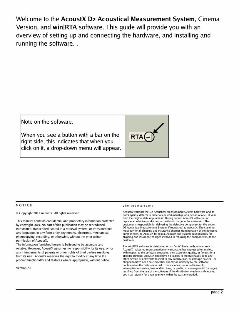
Note on the software:When you see a button with a bar on theright side, this indicates that when youclick on it, a drop-down menu will appear.
page 3
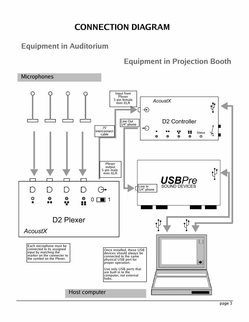
CONNECTION DIAGRAMEquipment in Auditorium
MicrophonesEquipment in Projection Booth
Once installed, these USBdevices should always beconnected to the samephysical USB port forproper operation.Use only USB ports thatare built in to thecomputer, not externalhubs.
Line In1/4" phone
Line Out1/4" phone
Input fromPlexer5-pin femalemini-XLR
75'interconnectcable
Plexeroutput5-pin malemini-XLR
Host computer
Each microphone must beconnected to its assignedinput by matching themarker on the connecter tothe symbol on the Plexer.
page 4
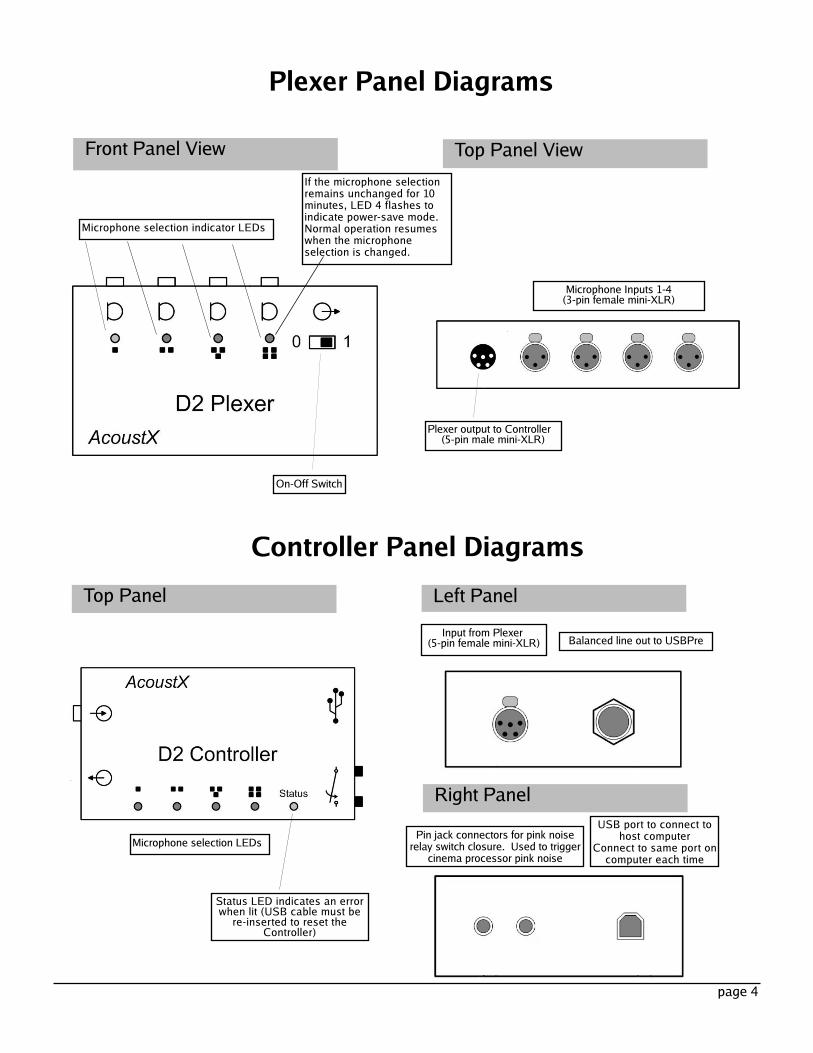
Plexer Panel DiagramsFront Panel View Top Panel View
On-Off Switch
Microphone selection indicator LEDs
If the microphone selectionremains unchanged for 10minutes, LED 4 flashes toindicate power-save mode.Normal operation resumeswhen the microphoneselection is changed.
Plexer output to Controller(5-pin male mini-XLR)
Microphone Inputs 1-4(3-pin female mini-XLR)
Controller Panel DiagramsTop Panel Left Panel
Right PanelMicrophone selection LEDs
Status LED indicates an errorwhen lit (USB cable must bere-inserted to reset theController)
Input from Plexer(5-pin female mini-XLR) Balanced line out to USBPre
Pin jack connectors for pink noiserelay switch closure. Used to triggercinema processor pink noise
USB port to connect tohost computerConnect to same port oncomputer each time
page 5
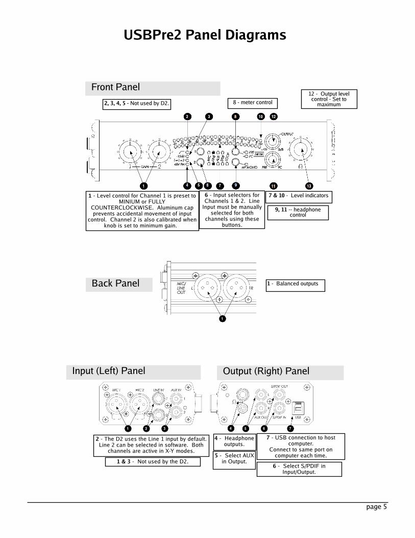
USBPre2 Panel Diagrams
Front Panel
Input (Left) Panel Output (Right) Panel
2, 3, 4, 5 - Not used by D2.
1 - Level control for Channel 1 is preset toMINIUM or FULLYCOUNTERCLOCKWISE. Aluminum capprevents accidental movement of inputcontrol. Channel 2 is also calibrated whenknob is set to minimum gain.
12 - Output levelcontrol - Set tomaximum
6 - Input selectors forChannels 1 & 2. LineInput must be manuallyselected for bothchannels using thesebuttons.
7 & 10 - Level indicators9, 11 -- headphonecontrol
2 - The D2 uses the Line 1 input by default.Line 2 can be selected in software. Bothchannels are active in X-Y modes.7 - USB connection to hostcomputer.Connect to same port oncomputer each time.1 & 3 - Not used by the D2. 6 - Select S/PDIF inInput/Output.
5 - Select AUXin Output.
4 - Headphoneoutputs.
8 - meter control
Back Panel 1 - Balanced outputs
Installation1. Install the USBPre2 Digital Audio Interface first.Please refer to the documentation accompanying theUSBPre for complete installation and operatinginstructions. Refer to the connection diagram and tothe USBPre panel diagrams in this document forinformation on proper connection of the device.(Note: The USBPre must be connected directly to aUSB input on the computer instead of through anexternal USB hub.) Under Windows Vista and 7, youmust set the sampling rate to 48 kHz 16 bit forRecording and Playback for the USBPre in theWindows Control Panel. You may also use theSoundDevices ASIO drivers available on theirwebsite. When using ASIO, you do not need to setthe sampling rate.
2. Connect the D2 Controller as shown in theconnection diagram. The Controller must beconnnected directly to a USB input on the computerinstead of through an external USB hub. When theController is connected, the computer should promptfor drivers for the device. The necessary drivers arefound on the D2 CD.
3. Insert the D2 software CD into an available driveon the host computer. Open the CD and double clickon "Setup". Follow the instructions and prompts ofthe installation procedure to install the win|RTAsoftware onto the host computer. A short-cut icon forwin|RTA can be placed on the desktop during theinstallation procedure.
4. Connect the remaining components of the D2Acoustical Measurement System (D2 Plexer andmicrophones) as shown in the connection and paneldiagrams.
5. Install the 9V alkaline battery in the Plexer openingthe battery cover on the back panel. If you want to use arechargeable battery, a 9V NiMH battery with a 250 mAhor greater rating is recommended.
6. Double-click on the short-cut icon placed on thedesktop to start the win|RTA software. Note that adefault configuration (preferences) will be created thefirst time the program is executed. The user shouldcustomize this information as appropriate in the Configpanels.
7. After installation, enable microphone calibration byselecting mic cal numbers in the Config menu. (See theConfig diagrams later in this document.) Themicrophone serial numbers are assigned with Mic 1 asthe lowest serial number through Mic 4 as the highestserial number. The "Mic Cal" checkbox must be selectedto enable mic calibration.
8. With the USBPre2 connected, select the "Interfaces"window in Config. Press "Select" and choose USBPre2from the list of available interfaces.
9. Finally, click "Save Configuration" to store thepreferences to disk.
page 6
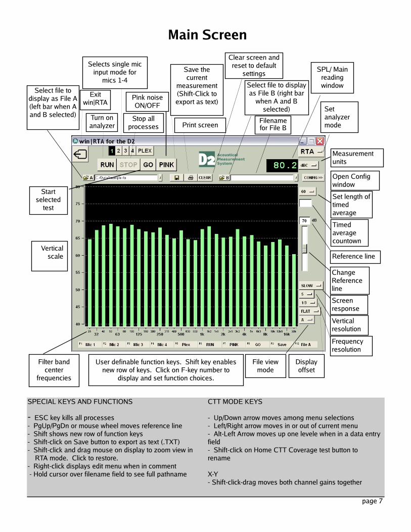
Main Screen
Print screen
Selects single micinput mode formics 1-4
Clear screen andreset to defaultsettingsSave thecurrentmeasurement(Shift-Click toexport as text)Exitwin|RTA
SPL/ MainreadingwindowSelect file todisplay as File A(left bar when Aand B selected)
Select file to displayas File B (right barwhen A and Bselected)Filenamefor File B
Setanalyzermode
MeasurementunitsOpen ConfigwindowSet length oftimedaverageTimedaveragecountownReference lineChangeReferenceline
Turn onanalyzer Stop allprocesses
Pink noiseON/OFF
Verticalscale
ScreenresponseVerticalresolutionFrequencyresolution
DisplayoffsetFile viewmodeUser definable function keys. Shift key enablesnew row of keys. Click on F-key number todisplay and set function choices.Filter bandcenterfrequencies
SPECIAL KEYS AND FUNCTIONS- ESC key kills all processes- PgUp/PgDn or mouse wheel moves reference line- Shift shows new row of function keys- Shift-click on Save button to export as text (.TXT)- Shift-click and drag mouse on display to zoom view inRTA mode. Click to restore.- Right-click displays edit menu when in comment- Hold cursor over filename field to see full pathname
CTT MODE KEYS- Up/Down arrow moves among menu selections- Left/Right arrow moves in or out of current menu- Alt-Left Arrow moves up one levele when in a data entryfield- Shift-click on Home CTT Coverage test button torenameX-Y- Shift-click-drag moves both channel gains together
page 7
Startselectedtest
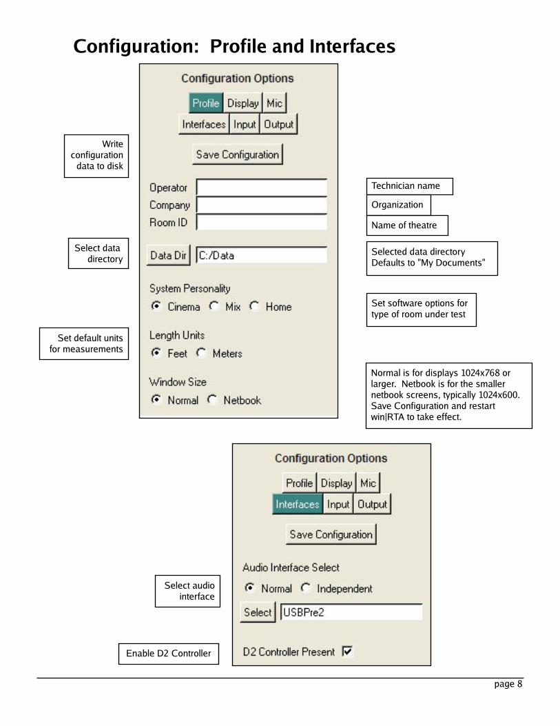
Technician nameOrganizationName of theatre
Select datadirectory
page 8
Selected data directoryDefaults to "My Documents"
Set software options fortype of room under testSet default unitsfor measurements
Select audiointerface
Enable D2 Controller
Configuration: Profile and Interfaces
Writeconfigurationdata to disk
Normal is for displays 1024x768 orlarger. Netbook is for the smallernetbook screens, typically 1024x600.Save Configuration and restartwin|RTA to take effect.
page 9
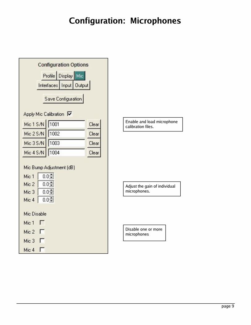
Disable one or moremicrophones
Enable and load microphonecalibration files.
Adjust the gain of individualmicrophones.
Configuration: Microphones
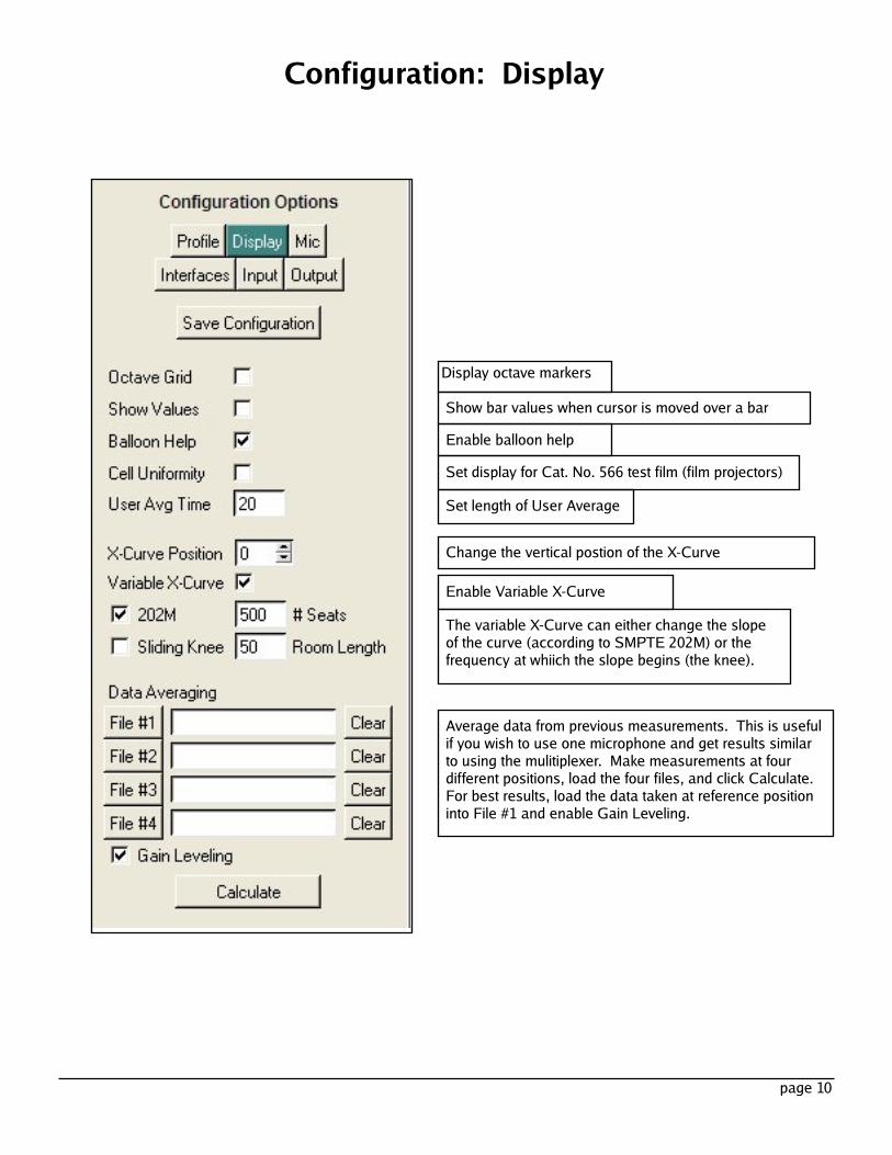
Display octave markersShow bar values when cursor is moved over a barEnable balloon help
Set length of User AverageSet display for Cat. No. 566 test film (film projectors)
Enable Variable X-CurveThe variable X-Curve can either change the slopeof the curve (according to SMPTE 202M) or thefrequency at whiich the slope begins (the knee).
page 10
Configuration: Display
Change the vertical postion of the X-Curve
Average data from previous measurements. This is usefulif you wish to use one microphone and get results similarto using the mulitiplexer. Make measurements at fourdifferent positions, load the four files, and click Calculate.For best results, load the data taken at reference positioninto File #1 and enable Gain Leveling.
page 11
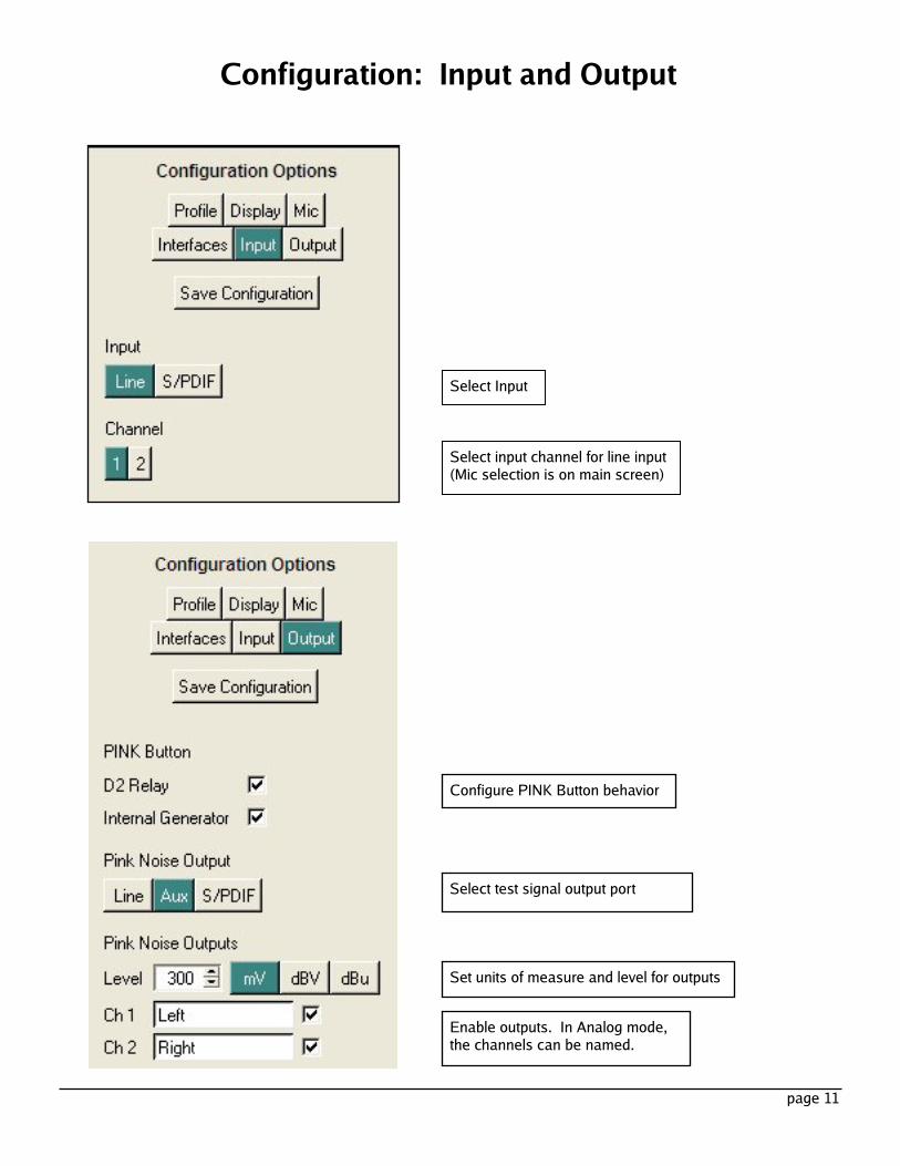
Configure PINK Button behavior
Select test signal output port
Set units of measure and level for outputs
Enable outputs. In Analog mode,the channels can be named.
Configuration: Input and Output
Select Input
Select input channel for line input(Mic selection is on main screen)
page 12
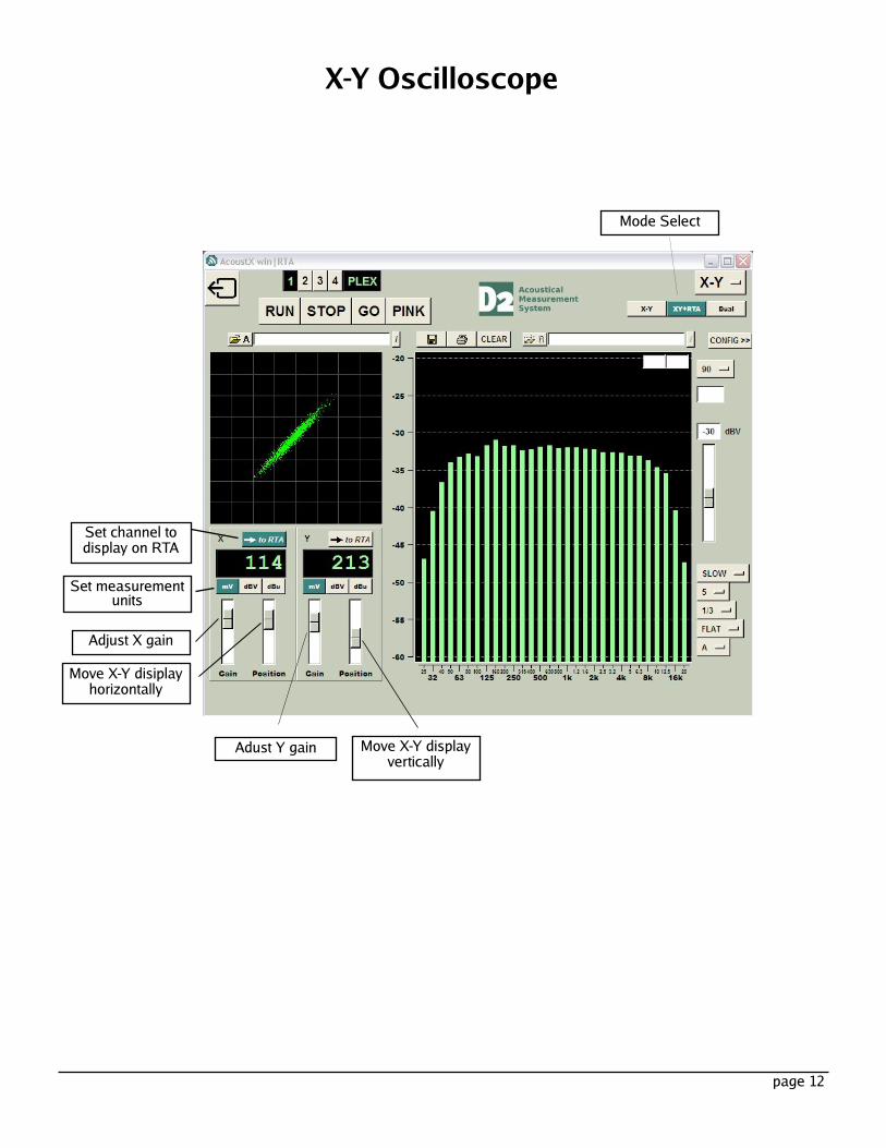
X-Y Oscilloscope
Mode Select
Set channel todisplay on RTASet measurementunits
Adjust X gainMove X-Y disiplayhorizontally
Adust Y gain Move X-Y displayvertically
page 13
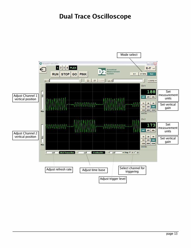
Dual Trace Oscilloscope
Adjust Channel 1vertical positionSetmeasurementunits
Mode select
Adjust trigger level
Select channel fortriggering
Set verticalgain
Setmeasurementunits
Set verticalgain
Adjust time base
Adjust Channel 2vertical position
Adjust refresh rate