Embed Size (px)
Citation preview
1
D-Link DP-301U
Fast Ethernet Print Server
Manual
Rev. 03 (November, 2007)

2
Contents
Package Contents ....................................................................................................4 Contents of Package: ........................................................................................4 System Requirements: ......................................................................................4
Introduction...............................................................................................................1 External Features .....................................................................................................3
Port Connector...................................................................................................3 Rear Panel Connectors .....................................................................................4 Network Cable Connector..................................................................................4 USB Port Connector ..........................................................................................4 DC Power Connector.........................................................................................4
Front Panel ................................................................................................................5 LED Indicators ...................................................................................................5
Setting up the DP-301U............................................................................................6 Installing the Print Server...................................................................................6 Power ON Self-Test ...........................................................................................7
Getting Started..........................................................................................................9 Using PS-Wizard.....................................................................................................10
Auto-Run Installation .......................................................................................10 PS-Wizard........................................................................................................11 Installing PS-Wizard ........................................................................................11 Using PS-Wizard .............................................................................................15
Using the Web Configuration ................................................................................21 Home ...............................................................................................................21 SETUP > LAN Setup .......................................................................................25 SETUP > Printer Setup....................................................................................26 ADVANCED > Advanced LAN .........................................................................34 ADVANCED > User Access .............................................................................36 ADVANCED > E-Mail Notification....................................................................38 ADVANCED > SNMP.......................................................................................40 MAINTENANCE > Password...........................................................................41 MAINTENANCE > Save/Restore Settings.......................................................42 MAINTENANCE > Firmware Upgrade.............................................................43 MAINTENANCE > Diagnostics........................................................................44 STATUS > Device Info .....................................................................................45 STATUS > Network..........................................................................................47 STATUS >Print Log..........................................................................................49 HELP................................................................................................................50

3
Reboot .............................................................................................................51 Refresh Printer Status......................................................................................52
TCP/IP Printing for Windows Vista .......................................................................53 TCP/IP Printing for Windows XP ...........................................................................64 TCP/IP Printing for Windows 2000........................................................................75 TCP/IP Printingfor Windows 98SE/ME .................................................................88 Unix/Linux Printing...............................................................................................101
Printing Text Files form Unix ..........................................................................101 Printing form BSD Unix Versions...................................................................102 Printing from SCO Unix System V/386..........................................................105 Printing from Solaris ......................................................................................107 Printing from Red Hat Linux...........................................................................108
Setting up Printing in Mac OS X Tiger (10.4) .....................................................115 Adding a Printer .............................................................................................117 AppleTalk-enabled or Bonjour-enabled Printers ............................................119
Setting up AppleTalk or LPR Printing in Mac OS X...........................................129 Setting up AppleTalk Printing in Mac OS 9 ........................................................134 Technical Specifications......................................................................................139 Contacting Technical Support.............................................................................140 Warranty and Registration...................................................................................141 Appendix: DP-301U Printer Compatibility List ..................................................145

4
Package Contents
Contents of Package:
D-Link DP-301U Pocket-Sized Print Server
Manual and Warranty on CD
Printed Quick Installation Guide
If any of the above items are missing, please contact your reseller.
System Requirements:
A computer with an installed Ethernet adapter
Windows Vista/XP/2000/NT4/ME/98SE/95
Apple Mac OS 9.x to MAC OS X 10.4.x
Linux, Solaris, SCO Unix, AIX
Internet Explorer 6.0 or above; Netscape Navigator version 6.0 or above, with
JavaScript enabled
Printer must support required operating system

1
Introduction The D-Link DP-301U Print Server is a packet size print server that connects to your
Ethernet/Fast Ethernet network anywhere you wish to locate printer services. The
DP-301U manages the flow of print files from workstations or file servers to
connected printers, delivering print jobs to printers much faster than a file server or a
PC acting as a print server can.
The DP-301U includes easy-to-use software to install on most Windows-based
networks. Protocol support for TCP/IP, NetBEUI, and AppleTalk are provided to
ensure seamless connection to major networking Operating Systems.
The DP-301U has a built in Web-Based management feature that allows users to
easily configure and manage multiple print queues through TCP/IP. The DP-301U
also supports Telnet as an alternative method to configure the unit.
The DP-301U improves network printing services in the following ways:
The DP-301U picks up the workload of managing print file traffic to its connected
printers. This provides workload relief to your file servers, and allows the file servers
full capacity to be used for file access or other direct services to network users. On
peer-to-peer networks, workstations can print directly to the Print Server without
increasing the load of another workstation or server.
The DP-301U’s USB printer port is USB 2.0 port, which can transmit to high-speed
laser printer much faster than a PC’s USB printer port. High-speed laser printer
connected to the Print Server’s USB port can be operated at their full capacity.

2
Because the DP-301U is very portable and inexpensive compared to a PC-based
print server, and Print Server connects to your file servers through the network,
printers can be deployed to locations of maximum convenience to users.
The DP-301U offers extraordinary flexibility, operating with all major network
operating systems and protocols:
TCP/IP
UNIX lpr/lpd (HP-UX, SunOS, Solaris, SCO, UnixWare, IBM AIX) Windows NT/2000,
Windows 95/98SE/ME, Windows XP/Vista, NetWare 5.x NDPS LPR Remote
Printing
NetBEUI
Windows NT/2000/XP, Windows 95/98SE/ME, Windows for Workgroups, Microsoft
LAN Manager, IBM LAN Server
AppleTalk
MacOS EtherTalk
Furthermore, the print server features a useful software: PS-Wizard. PS-Wizard is
an user-friendly program used to complete further settings for the print server, and
assist you to easily add a printer on your computer. See also the “Using The
PS-Wizard” chapter in this manual for the details. The print server also supports
configuration and management via the Telnet protocol for networks without
Windows-compatible machines.
3
External Features
Port Connector The DP-301U’s USB port is located on its rear panel. The port is configurable using
the Web Configuration Interface or the print server’s Telnet interface. The Print
Server’s Web configuration permits users to configure settings through the web
browser.
Default IP Address of DP-301U is set as automatically getting from DHCP server or
Router which build-in DHCP server.
NOTE: The PC’s IP Address must be in the same subnet as the print server’s IP
Address for the two devices to communicate. (For example, if print server’s IP
Address is 192.168.0.10, with a subnet mask of 255.255.255.0, then your
computer’s IP Address should be 192.168.0.x, where x is a value between 1-254,
excluding 10.)

4
Rear Panel Connectors
Network Cable Connector The Print Server’s rear panel features an RJ-45 connector for connection to
10Base-T Ethernet cabling or 100Base-TX Fast Ethernet cabling (which should
be Category 5 twisted-pair cable). The port supports the NWay protocol, allowing
the Print Server to automatically detect or negotiate the transmission speed of the
network.
USB Port Connector The rear panel of the print server features the USB port connector. Plug this
connector directly into the USB port on your network printer via a USB cable.
Reset Button Press and release this button to reset the Print Server; or press and hold this button
for three seconds until the USB LED on the front panel light up and then release the
button, the Print Server will resume the factory default settings.
DC Power Connector The DC power input connector is located on the Print Server’s rear panel and is
labeled DC 5V.

5
Front Panel
LED Indicators The front panel of the print server features three LED indicators:
Power
Steady green confirms that the Print Server is powered ON.
USB
Lights up to indicate printing activity.
LAN
Steady green confirms that the Print Server has a good connection to the Ethernet or
Fast Ethernet network. The indicator blinks off briefly to indicate that the Print Server
is receiving or transmitting from the network.
These three indicators are also used by the Print Server’s Power-ON Self Test
(POST) to indicate any hardware failures.

6
Setting up the DP-301U
Installing the Print Server WARNING: Configuration problems may result if the Print Server is powered up
without first establishing its network connection.
Follow this procedure to avoid complications at the configuration stage.
1. Confirm proper operation of the printers to be connected to the DP-301U.
2. When you have confirmed proper operation of the printer, switch its power OFF.
3. Confirm that your network is operating normally.
4. Connect the DP-301U RJ-45 Connector to the network, using an Ethernet CAT5
cable.
5. While the printer is powered OFF, install the DP-301U USB port connector into the
USB port on the network printer.
6. Switch on the connected printer.
7. Plug the AC power adapter’s DC output plug into the DC 5V power socket on the
rear panel of the Print Server.
8. Plug the power adapter into a power outlet. This will supply power to the Print
Server, as it has no external power switch. The green Power LED on the Print
Server’s front panel should illuminate steadily, and the Print Server’s Self-Test will
proceed.
7
Power ON Self-Test Every DP-301U has been factory-tested to operate properly.
When the DP-301U is powered ON, it also automatically performs a Self-Test on
each of its major components. The final result of the Self-Test is signaled by the
state of the USB LED indicator following the Self-Test. Preliminary to the actual
component tests, the three LED indicators are tested to confirm their steady and
flashing operation.
Immediately after power-up, all three of the green LEDs should illuminate steadily
for several seconds. Then the USB LED should light OFF. Irregularity of any of the
three LEDs during these LED tests may mean there is a problem with the LEDs
themselves.
The actual component tests immediately follow the LED tests. A normal (no fault)
result is signaled by a simultaneous flashing of the USB LED three times, followed
by a quiescent state with the USB LED dark.
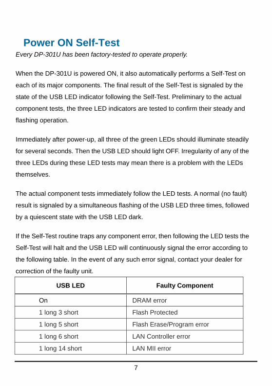
If the Self-Test routine traps any component error, then following the LED tests the
Self-Test will halt and the USB LED will continuously signal the error according to
the following table. In the event of any such error signal, contact your dealer for
correction of the faulty unit.
USB LED Faulty Component
On DRAM error
1 long 3 short Flash Protected
1 long 5 short Flash Erase/Program error
1 long 6 short LAN Controller error
1 long 14 short LAN MII error

8
USB LED Faulty Component
1 long 18 short USB error
1 long 19 short PCI error

9
Getting Started Below is a sample network using the DP-301U. The DP-301U has a built- in
Web-based management feature that allows users to easily configure and
manage multiple print queues through TCP/IP.
For a list of printers that are compatible with the DP-301U, please see the Appendix
in this manual. The compatibility list is not comprehensive. Even if it is not included
in the list, your printer may be compatible with the DP-301U.

10
Using PS-Wizard
This chapter will introduce you the installation and operation of a useful software
program – PS-Wizard.
Auto-Run Installation Insert the Installation CD-ROM into your computer’s CD-ROM drive to initiate the
Auto-Run program. The content of the Installation CD-ROM includes:
View Quick Installation Guide - click to preview the Quick Installation Guide in PDF format for step-by-step instructions of the print server Installation.
View Manual – click to preview the User's Guide in PDF format for detailed information of the print server.
Install Acrobat Reader – click to launch Acrobat Reader for the viewing and printing of PDF files in the Installation CD-ROM.
Install PS-Wizard – click to install PS-Wizard to complete further settings for the print server, such as:
- Changing IP address
- Adding a printer on your computer in the easiest way.
Close – click to close the Auto-Run program.

11
PS-Wizard To avoid the conflict in your network, you can use PS-Wizard to change the related
settings of your print server (such as the IP address) after finishing the installation of
PS-Wizard on your PC.
Installing PS-Wizard 1. Click the PSWizardSetup icon of the Installation CD-ROM, and then the system
will prompt a window for you to select a desired setup language from its
pull-down menu. After done the selection of language, click OK button to
continue.

12
2. Click Next> button in the welcome window of InstallShield Wizard.
3. Specify the destination location by pressing Browse… button. Otherwise,
leave the default setting and click Next> button to continue.
13
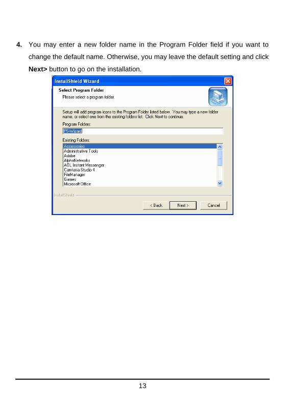
4. You may enter a new folder name in the Program Folder field if you want to
change the default name. Otherwise, you may leave the default setting and click
Next> button to go on the installation.

14
5. The InstallShield Wizard starts to install the software, and the Progress bar
indicates the installation is proceeding until the following window shows up. Click
Finish button to complete the installation.
After installing the program, the application program for the print server is
automatically installed to your computer, and creates a folder in Start
Programs PS-Wizard.

15
Using PS-Wizard PS-Wizard, supports for Windows 2000/XP/2003/Vista, is a simple and useful tool
for you easily adding a printer on your computer in order to quickly start your
printing task without any complicated configuration. That is, the main goal and
advantage of the PS-Wizard is to let you add a printer on your PC in the easiest
way.
Furthermore, the PS-Wizard also allows you to set up IP addresses of print server,
such as IP address, Subnet Mask address, and default Gateway address.
Go to Start Programs PS-Wizard, and select PS-Wizard.

16
Print Server: This field allows you to manually discover the connected print
server and to do further configuration of the print server that is selected from
the list.

17
LAN: You may also to specify dynamic or static IP address for your print
server. Then click Apply button to implement the new setting.
Port Information: This is the main function of the PS-Wizard for you to
easily add a printer on your computer.
To add a printer, click , then the following window will display.

18
The wizard provides three ways for you to select printer driver:
1. Show current installed drivers:
You may select this option, “Show currently installed drivers”, to check if the
same printer driver already existed for use. If not, you may try the next method.
After done the selection of printer driver, click Next> button to continue.
2. Select from manufacturer list:
Check this option, “Select from manufacturer list”, to manually select your printer
from drop-down menus by brand and model. Click Next> button to continue when
you find a desired driver. If not, try the last way (Have Disk). After done the
selection of printer driver, click Next> button to continue.
3. Have Disk:
Click Have Disk button to bring up the following window. Insert the manufacture’s
installation CD-ROM to install the printer driver. After the correct driver is selected,
click OK button to continue.

19
After done the selection of printer driver, the wizard will ask you to confirm your
selection again in the following window. Beside, you are allowed to edit the name
of the printer in the field “Network Printer Name” and enable this printer as the
default printer by checking the box “Use this printer as the default printer for
Windows-based programs”.
After you done the verification and configuration in the following window, click
Next> button to continue. Then the printer (e.g. HP Laser 2000 used in this
manual) will be auto-created in Windows’ Printers and Faxes window as the
following illustration.
20
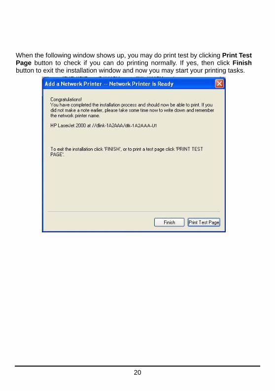
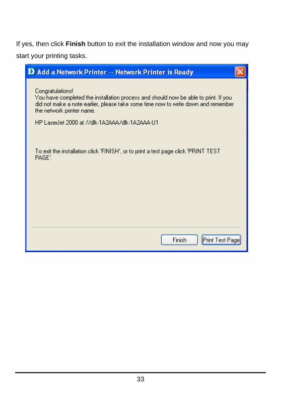
When the following window shows up, you may do print test by clicking Print Test Page button to check if you can do printing normally. If yes, then click Finish button to exit the installation window and now you may start your printing tasks.

21
Using the Web Configuration
Home To begin managing the DP-301U, simply launch the browser (e.g. Internet
Explorer 6.0 used in this manual) you have installed on your computer and direct it
to the URL address: dlink-xxxxxx, where xxxxxx are the last six digits of
DP-301U’s MAC address. The MAC address can be found on the bottom side of
the DP-301U device.
When you enter the correct URL, a password input dialog will pop up the following
screen. Input “admin” in the User name field, leave the Password field as blank,
and then click OK button.

22
Then the main screen of the print server’s configuration will appear (see below). In
addition to the product information, you can access and control the print server’s
configuration through five links on the top of this main screen: Setup, Advanced,
Maintenance, Status, and Help. You may click a desired link from the bar, to
display its submenu and select a desired option listed in the left column, and then
the corresponding content will show up in the center column.

23
SETUP > Print Server Setup
The Print Server Setup screen allows you to modify the Print Server Name and
Port Name, as below shows. D-Link does not recommend changing these
settings unless asked to do so by your network administrator.
Print Server Name
In this field, you can configure the basic information of print server. The basic
information contains a name of the print server, assigned in Server Name field,
and a location for the print server, assigned in Location (optional) field.
24
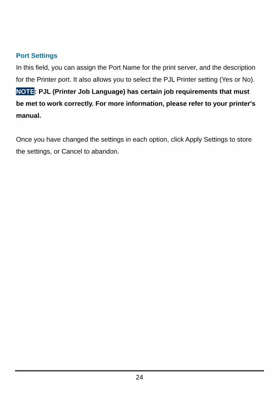
Port Settings
In this field, you can assign the Port Name for the print server, and the description
for the Printer port. It also allows you to select the PJL Printer setting (Yes or No).
NOTE: PJL (Printer Job Language) has certain job requirements that must
be met to work correctly. For more information, please refer to your printer's
manual.
Once you have changed the settings in each option, click Apply Settings to store
the settings, or Cancel to abandon.
25
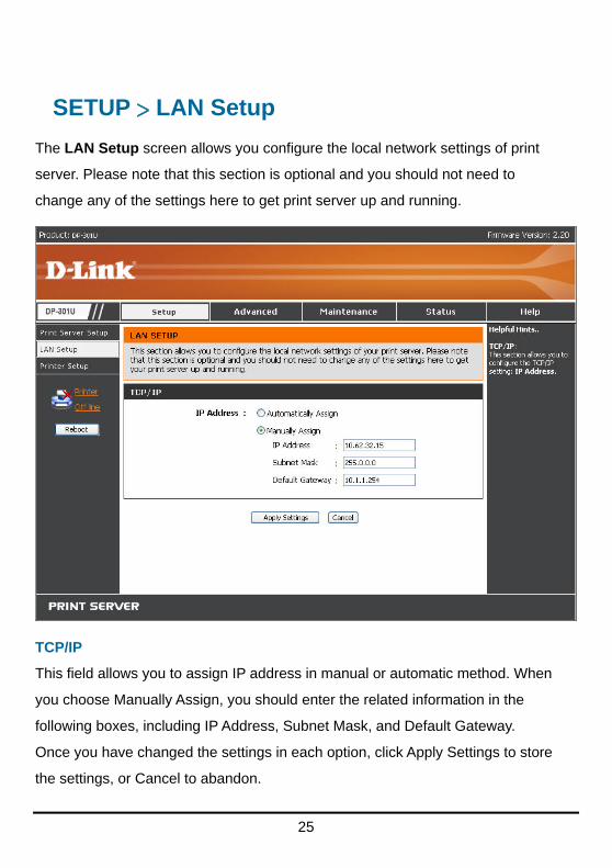
SETUP > LAN Setup
The LAN Setup screen allows you configure the local network settings of print
server. Please note that this section is optional and you should not need to
change any of the settings here to get print server up and running.
TCP/IP
This field allows you to assign IP address in manual or automatic method. When
you choose Manually Assign, you should enter the related information in the
following boxes, including IP Address, Subnet Mask, and Default Gateway.
Once you have changed the settings in each option, click Apply Settings to store
the settings, or Cancel to abandon.

26
SETUP > Printer Setup
The Printer Setup screen allows you install the printer drivers for the printer
currently connected to your print server.
Network Printer Wizard
Clicking Next to download and run a windows wizard program which will install a
network printer onto your computer. When you click Next you will be asked to
download and run some software.

27
The above screen is the Network Printer Wizard so please click RUN, and if a
second window appears as below click RUN again.

28
Please select the printer required, then click NEXT to continue.
The wizard provides three ways for you to select printer driver:
1. Show current installed drivers:
You may select this option, “Show currently installed drivers”, to check if the
same printer driver already existed for use. If not, you may try the next method.
After done the selection of printer driver, click Next> button to continue.

29
2. Select from manufacturer list:
Check this option, “Select from manufacturer list”, to manually select your printer
from drop-down menus by brand and model. Click Next> button to continue when
you find a desired driver. If not, try the last way (Have Disk). After done the
selection of printer driver, click Next> button to continue.

30
3. Have Disk:
Click Have Disk button to bring up the following window. Insert the manufacture’s
installation CD-ROM to install the printer driver. After the correct driver is selected,
click OK button to continue.

31
After done the selection of printer driver, the wizard will ask you to confirm your
selection again in the following window. Beside, you are allowed to edit the name
of the printer in the field “Network Printer Name” and enable this printer as the
default printer by checking the box “Use this printer as the default printer for
Windows-based programs”.
After you done the verification and configuration in the following window, click
Next> button to continue. Then the printer (e.g. HP Laser 2000 used in this
manual) will be auto-created in Windows’ Printers and Faxes window as the
following illustration.
32
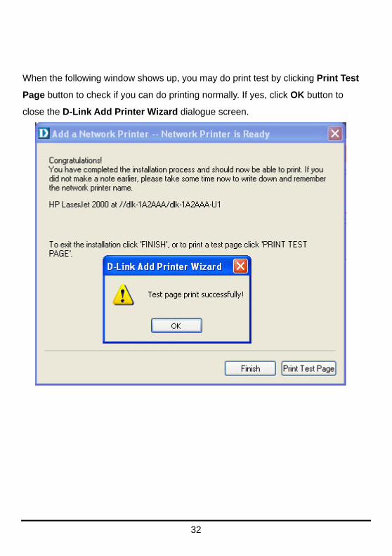
When the following window shows up, you may do print test by clicking Print Test
Page button to check if you can do printing normally. If yes, click OK button to
close the D-Link Add Printer Wizard dialogue screen.
33
If yes, then click Finish button to exit the installation window and now you may
start your printing tasks.

34
ADVANCED > Advanced LAN
The Advanced LAN screen allows you to further network setting of print server,
while you are recommended better not to change the settings unless instructed to
modify the setting by your network administrator. The Advanced LAN screen
contains these fields: TCP/IP, Microsoft Network, and AppleTalk.

35
TCP/IP
This field contains four options that allow you to configure the TCP/IP setting:
DNS Server Address, UPnP, Mac Bonjour/Rendezvous, and Second HTTP
Port.
UPnP: This option allows you to enable or disable UPnP function.
Mac Bonjour/Rendezvous: This option allows you to enable or disable Mac
Bonjour/Rendezvous function.
Second HTTP Port: This option allows you to enable or disable Second
HTTP Port for remote Web Configuration and IPP Printing.
Microsoft Network
Enter the name of the Workgroup that you want the print server associated with in
this field.
AppleTalk
Enter the AppleTalk Zone name in the box. In the following options, enter the
related configuration, such as the printer type.
Chooser Name: Display the print server's port name.
Printer Type: Enter the printer's type in this box.
PostScript Level: Select from the pull-down menu (Level 1 or Level 2).
Font Group: Select from the pull-down menu.
Once you have changed the settings in each option, click Apply Settings to store
the settings, or Cancel to abandon.

36
ADVANCED > User Access
The User Access screen allows you to create and maintain an authorized list of
users that are allowed to access the print server.
User Access
By configuring the Enable Authorised User List option (Yes), the user in the
User List is permitted to access the print server. Any user who is not added in the
User List will not be allowed to access the print server. Once you have changed
the settings in each option, click Apply Settings to store the settings, or Cancel to
abandon.

37
Authorised Users
You can add or delete any user to or from the User List. The User List at the
bottom of the screen displays the current defined user and related information for
the print server.

38
ADVANCED > E-Mail Notification
The E-Mail Notification screen allows you to assign an E-mail address to the
print server, so that your mail of the account can be printed out directly through
the printer (ASCII text only). This screen also allow you choose where to send an
email when the printer status changes.

39
Enable E-mail Notification
You can set the print server to send an alert message when the printer status
changes through E-mail. To enable this function, set the Enable e-mail
notification option to Yes. Then, input the administrator's E-mail address in the
Destination e-mail Address field.
E-mail Account Details
You can assign an E-mail address to the print server, so that your mail of the
account can be printed out directly through the printer (ASCII text only). To enable
this function, enter the E-mail account in the Print Server E-mail Address field.
Then enter the server address, used to receive your E-mail here, in the Incoming
E-mail (POP3) Server Address field. For outgoing E-mail (SMTP) Server
Address field, enter the server address that is used to send your E-mail here.
If your mail server needs to verify the user when sending E-mail, Print Server will
apply the E-mail Account (POP3) Name and E-mail Account (POP3)
Password to the mail server.
E-mail Printing
This section is for you to do E-mail Printing configuration, including:
E-mail Printing (ASCII Text Only): Allows you to enable or disable the E-mail
printing.
Check E-mail Interval: Allow you to set up a time interval in minute in order to
check/receive E-mail periodically.
After done the configuration, click Apply Settings to restore the new configuration,
or Cancel to abandon.

40
ADVANCED > SNMP
The SNMP screen allows you to use SNMP (Simple Network Management
Protocol) to manage complex networks.
SNMP Management
Community 1/2/3: Enter a name in the Name frame, and configure the Access
Right by selecting Read Only or Read/ Write from the pull-down menu.

41
MAINTENANCE > Password
The Password screen allows you to change the password of the print server by
entering the current password in Current Password field and new password in
New Password and Confirm Password fields. After done the configuration, click
Apply Settings to enable and restore the new password, or Cancel to abandon. Be
aware that the default password of the print server is blank.

42
MAINTENANCE > Save/Restore Settings
The Save/Restore Settings screen not only allows you to save the current
configuration in a computer for backup by clicking Save, but also allows you to
reload a configuration that you saved before by clicking Browse to direct to the
backup file, and then clicking Update Settings for reloading. Beside, you are also
allowed to return the print server to the default settings by clicking Restore
Device.
43
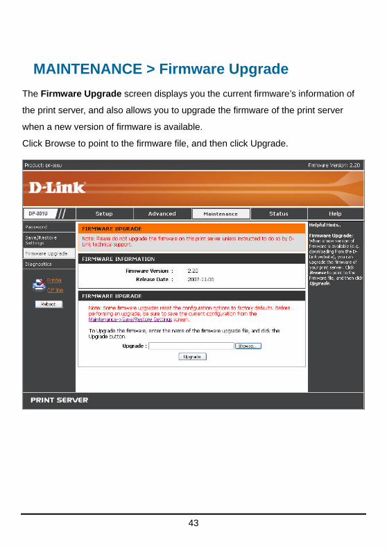
MAINTENANCE > Firmware Upgrade
The Firmware Upgrade screen displays you the current firmware’s information of
the print server, and also allows you to upgrade the firmware of the print server
when a new version of firmware is available.
Click Browse to point to the firmware file, and then click Upgrade.

44
MAINTENANCE > Diagnostics
The Diagnostics screen allows you to test the printing for USB port of the print
server. After done the port selection, click Print Test Page to print a test page.

45
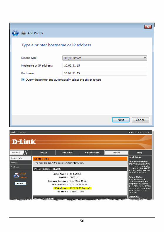
STATUS > Device Info
The Device Info screen displays the status of your print server, printer, and
network for your reference.

46
Print Server Status
This field displays the information of the print server about the firmware version,
MAC/IP address, and up time.
Printer Status
The items in this field display the information of the printer, such as the given
name for the printer, speed, printer status, and status of your printing tasks, etc.
LAN Status
You can monitor the networking status in this field, including the network
connection, speed, and the packets status.

47
STATUS > Network
The Network screen displays the general Network status of your print server,
including:
Auto IP
This field contains the current settings of TCP/IP, including DHCP/BOOTP, UPnP,
and Mac Bonjour/Rendezvous. The items in this field are configured in Advanced
Advanced LAN TCP/IP.
TCP/IP Printing
In this field, you can monitor the status of your printing tasks through TCP/IP.
Microsoft Network Printing
In this field, you can monitor the status of your printing tasks through Microsoft
Network.
Mac AppleTalk Printing
In this field, you can monitor the status of your printing tasks through Mac
AppleTalk.

48

49
STATUS >Print Log
The Print Log screen displays the printing record of the authorized users.
Print Log
The items in this field display the user(s) information, which include the user(s)
MAC address, IP address, name, and status of printing tasks.

50
HELP
The Help screen provides you brief information about the print server for your
reference.
51
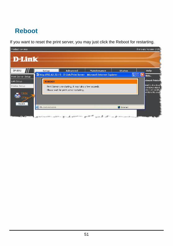
Reboot
If you want to reset the print server, you may just click the Reboot for restarting.

52
Refresh Printer Status
Click Printer to refresh printer status.

53
TCP/IP Printing for Windows Vista Go to Start Control Panel Printers.

54
Click Add a printer.
Select the first option, Add a local printer, and then click Next.

55
Select the second option, Create a new port, and highlight Standard TCP/IP
Port from the pull-down menu. Click Next.
Type the IP address of the print server (e.g. 10.62.31.15 used in this manual),
which can be referred from the PRINTER SERVER STATUS of the print server’s
Web configuration, and then the Port Name will automatically be filled in. Click
Next
56

57
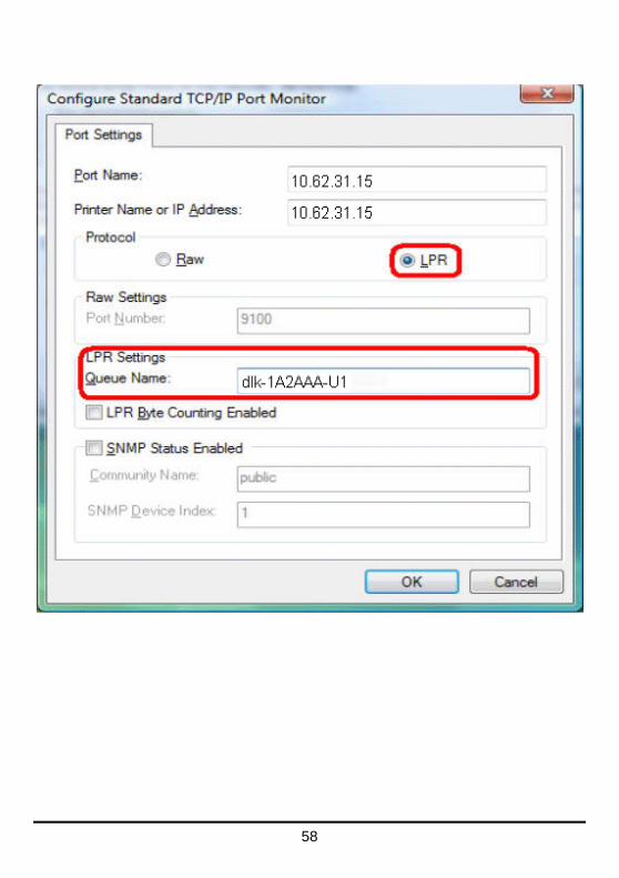
Select Custom and click Settings.
Then the follow screen will shows up, select LPR from the Protocol field.
Then enter the Queue Name, which can be referred from PRINTER STATUS of
the print server’s Web configuration, in the LPR Settings field. Click OK.
58

59
60
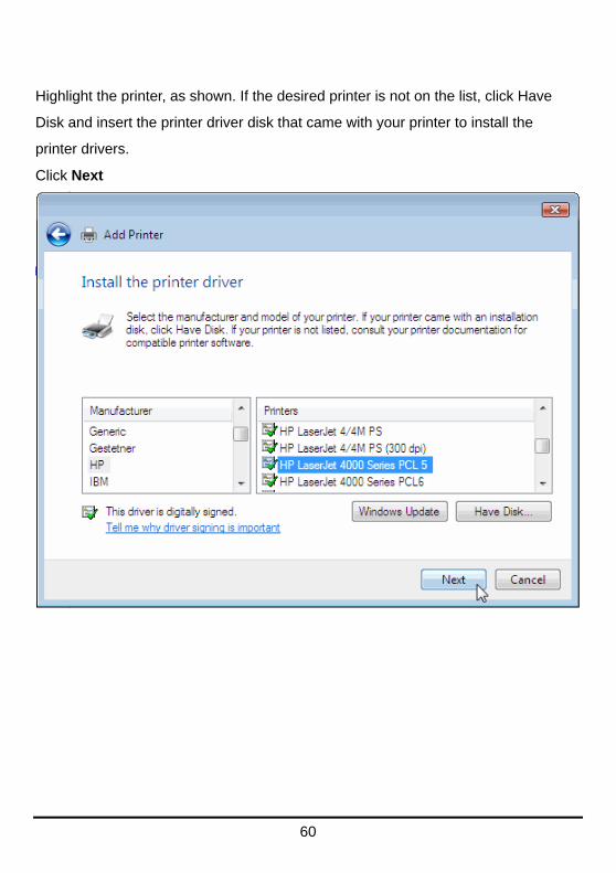
Highlight the printer, as shown. If the desired printer is not on the list, click Have
Disk and insert the printer driver disk that came with your printer to install the
printer drivers.
Click Next

61
Click Next.

62
After clicked Print a test page, a small dialogue box will show up as below. Click
Close.

63
Click Finish.
The printer is now ready for printing with Windows Vista on your network.

64
TCP/IP Printing for Windows XP Go to Start Printers and Faxes Add a Printer.
When the following screen shows up, click Next.
65
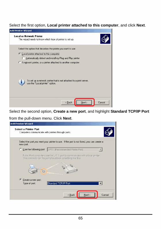
Select the first option, Local printer attached to this computer, and click Next.
Select the second option, Create a new port, and highlight Standard TCP/IP Port
from the pull-down menu. Click Next.

66
Type the IP address of the print server (e.g. 10.62.31.15 used in this manual),
which can be referred from the PRINTER SERVER STATUS of the print server’s
Web configuration, and then the Port Name will automatically be filled in. Click
Next

67
Select Custom and click Settings.

68
Then the follow screen will shows up, select LPR from the Protocol field.
Then enter the Queue Name, which can be referred from PRINTER STATUS of
the print server’s Web configuration, in the LPR Settings field. Click OK.

69
70
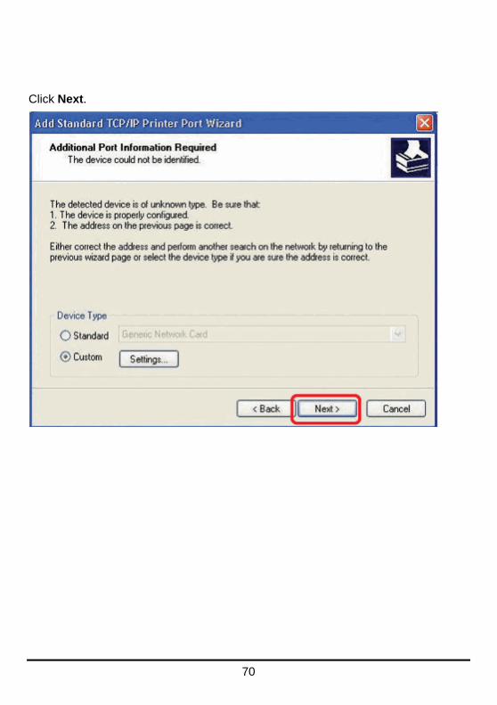
Click Next.

71
Click Finish.

72
Highlight the printer, as shown. If the desired printer is not on the list, click Have
Disk and insert the printer driver disk that came with your printer to install the
printer drivers.
Click Next

73
At this screen, you can input a name for the printer, and then click Next
Select Yes to print a test page, click Next.

74
Click Finish. The printer is now ready for printing with Windows XP on your
network.
75
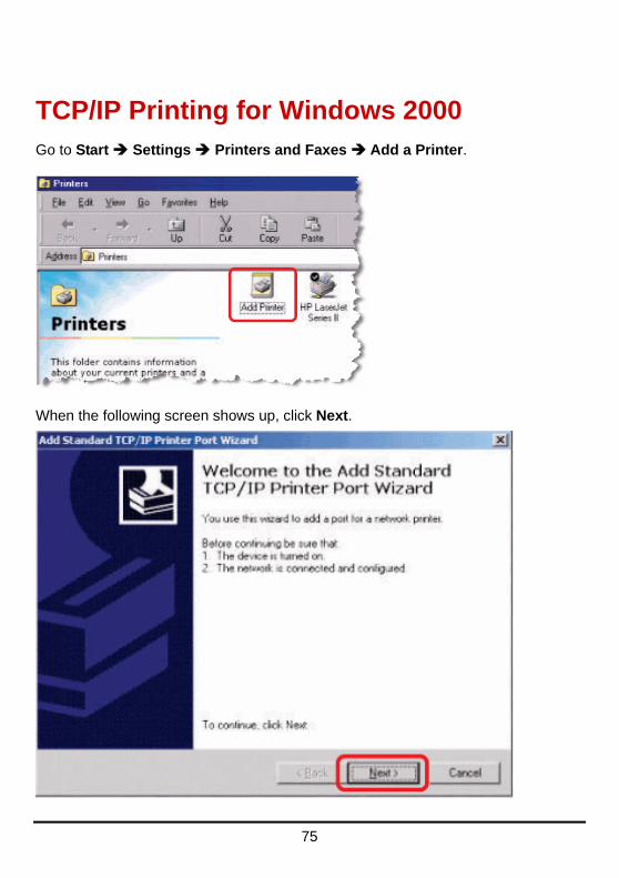
TCP/IP Printing for Windows 2000 Go to Start Settings Printers and Faxes Add a Printer.
When the following screen shows up, click Next.

76
Select the first option, Local printer attached to this computer, and click Next.

77
Click Next.
Select the second option, Create a new port, and highlight Standard TCP/IP Port
from the pull-down menu. Click Next.

78
Click Next.

79
Type the IP address of the print server (e.g. 10.62.31.15 used in this manual),
which can be checked from the PRINTER SERVER STATUS of the print server’s
Web configuration, and then the Port Name will automatically be filled in. Click
Next

80
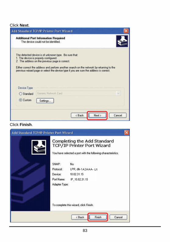
Select Custom and click Settings.

81
Then the follow screen will shows up, select LPR from the Protocol field.
Then enter the Queue Name, which can be referred from PRINTER STATUS of
the print server’s Web configuration, in the LPR Settings field. Click OK.

82
83
Click Next.
Click Finish.

84
Highlight the printer, as shown. If the desired printer is not on the list, click Have
Disk and insert the printer driver disk that came with your printer to install the
printer drivers.
Click Next.

85
At this screen, you can input a name for the printer, and then click Next
Select the first option, Do not share this printer, and click Next.

86
Select Yes to print a test page, click Next.

87
Click Finish. The printer is now ready for printing with Windows 2000 on your
network.

88
TCP/IP Printing for Windows 98SE/ME Go to Start Settings Control Panel. Double click on Network, and then
click Add.

89
Highlight Client and click Add.
At this window, click Have Disk.

90
1. Insert the DP-301U CD-ROM into your CD-ROM drive. Select the letter
representing the CD-ROM drive on your computer from the pull-down menu.
2. Double-click on the folder lpr.
3. Highlight lpr.inf
4. Click OK.
Click OK to accept the location of the file.

91
You should now be back to the Network Properties Page. Highlight LPR for
TCP/IP Printing and click Properties.

92
Click Add Port.
Type in the IP address and Port Name of the print server, which can be referred
from the PRINTER SERVER STATUS and PRINTER STATUS of the print
server’s Web configuration, in the corresponding field, and then click OK. (The IP
Address and Port Name here are just for example only.)

93
94
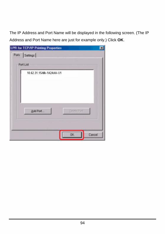
The IP Address and Port Name will be displayed in the following screen. (The IP
Address and Port Name here are just for example only.) Click OK.

95
Click OK.
Windows will ask for a restart.
Click Yes.

96
Once your computer has rebooted, click on Start Settings Printers Add
Printer. When the Add Printer Wizard screen appears, click Next.
Select Network Printer and click Next.

97
Type in the path if you know it; otherwise, click Browse.
At the following screen, browse for the printer port and highlight the port (e.g.
dlink-1D6FA3 in this manual). Click OK.

98
If the network path is not specified, type in the IP Address and Port Name of the
print server. Select Yes or No to enable or disable printing from MS-DOS based
programs. Click Next.

99
Highlight the printer, as shown. If the desired printer is not on the list, click Have
Disk and insert the printer driver disk that came with your printer to install the
printer drivers. Click Next.
Click Next

100
Select Yes to print a test page. Click Finish.
To check whether the printer is installed, go to Start Settings Printers.

101
Unix/Linux Printing
Printing Text Files form Unix
Text files on Unix systems contain lines that end with “newline” characters, as
opposed to MS-DOS and Windows-related operating systems that end with a
carriage return followed by a linefeed. Most printers require a carriage
return/linefeed pair at the end of each line, making it necessary for some
translation to be done before Unix text files can be printed on most printers.
For this purpose, you can define two “printers” for the same printer port, one that
prints to the port itself, and one that prints to the port name with _TEXT added to
the name. Files printed to the second port will be translated so that the printer has
the carriage return/linefeed pairs that it needs.
For example, you could define a printer hp5l that prints to port PS-142634-P1,
and a printer hp5lt that prints to port PS-142634-P1_TEXT. Your graphics files
could then be printed to the hp5l printer, and “raw” text files could be printed to
the hp5lt printer.

102
Printing form BSD Unix Versions
For “flavors” of the Unix operating system derived from or related to the BSD
releases, such as SunOS 4.x, Linux, BSD/OS, FreeBSD, or NetBSD, you can use
the following procedure to enable users to print to a printer connected to your
D-LINK network print server:
1. Log in as the superuser (root).
2. Add an entry for the print server in the host’s /etc/hosts file, giving a hostname
for the print server’s IP address. A line in /etc/hosts contains an IP address
and one or more aliases for the host . For example:
202. 39. 74. 40 ps-142634 ps-142634.dlink.com.tw
If you use DNS (the Domain Naming Services protocol), you can add an address
record entry to your DNS database for the print server.
3. Create a spool directory for the printer:
◊ On SunOS systems, create the directory as a subdirectory of /var/spool,
with the same name as the printer (e.g., /var/spool/hp5l ).
◊ On Linux systems, create the directory as a subdirectory of /user/spool
/lp.
◊ On BSD/OS, FreeBSD, or NetBSD systems, create the directory as
subdirectory of /var/spool.
4. Change the owner and permissions of the directory so that it is owned and
writable by group daemon, using the following commands:

103
chown bin.daemon /var/spool/hp5l
chmod 775 /var/spool/hp5l
5. Add an entry for the printer to /etc/printcap, similar to the following:
hp5l:\
:lp=:sd=/var/spool/hp5l :mx#0:\
:rm=ps-142634:rp=ps-142634-p1:
The meaning of each of the entries is described below. The directory path in the
sd spool directory entry should match the directory name you created above. If
your entry requires more than one line you can escape the newline with a
backslash.
6. Issue the command
lpc start hp5l
to start a spool daemon for the printer. The printer will now be available for use.
7. Optionally, add another printcap entry (and issue another lpc start command)
for a second printer, using the port_TEXT port. This second printer name can be
used for printing text files.
Entries in /ect/printcap begin with a name for the printer or a list of name,
separated by | (a vertical bar). The entries used above are:
◆ lp= The lp entry is used to specify a local printer device.
Since the printer is a remote printer, this entry should be blank.

104
◆ sd=dir The location of the printer’s local spool directory.
◆ mx#blocks The limit for print job files in the local spool directory;
0 means no limit.
◆ rm=address The host where the remote printer is located, in this case
the D-Link print server.
◆ rp=printer The name of the printer on the remote host.
For the D-Link print server, the port name should be used.
Note: this entry is case-sensitive.
105
Printing from SCO Unix System V/386
To allow printing to a printer attached to your D-LINK network print server from a
SCO Unix System V/386 host.
1. Login as the superuser (root).
2. Add an entry for the print server in the host’s /etc/hosts file, giving a hostname
for the print server’s IP address. A line in /etc/hosts contains an IP address
and one or more aliases for the host. For example:
202.39.74.40 ps-142634 ps-142634.dlink.com.tw
If you use DNS (the Domain Naming Services protocol), you can add an address
record entry to your DNS database for the print server.
3. Change to the /dev directory, and issue the command
mkdev rlp
4. The script will ask:
Do you want to install or delet remote printing (i/d/q)?
Answer i and press Enter to continue.
5. The script will ask:
Do you want to change the remote printer description file
/etc/printcap (y/n)?
Answer y and press Enter to continue.
6. The script will ask:
Please enter the printer name (q to quit):
Enter an alias for the printer on the local machine and press Enter. This name
should be the same as the destination port name.

106
7. Answer r (remote printer) to the question
Is printer a remote printer or a local printer (r/l)?
8. When prompted with the question:
Please enter the name of the remote host that printer is
attached to:
then enter the address of the D-Link print server. You can use the name you
added to /etc/host in the step above.
9. Confirm that your entries are correct.
Is this correct? (y/n)
10. Answer the question:
Would you like this to be the system default printer? (y/n)
11. When you are done adding remote printers, enter q for the printer name.
12. Answer y to the question
Do you want to start remote daemon now (y/n)?
Once remote printing is set up, you can use the lp command to print jobs to the
new printer. For more information, consult your SCO Unix documentation.

107
Printing from Solaris
To allow printing from a Sun Solaris workstation,
1. Log in as the superuser (root).
2. Add an entry for the print server in the host’s /etc/hosts file, giving a hostname
for the print server’s IP address. A line in /etc/hosts contains an IP address
and one or more aliases for the host . For example:
202.39.74.40 ps-142634 ps-142634.dlink.com.tw
If you use DNS (the Domain Naming Services protocol), you can add an address
record entry to your DNS database for the print server.
3. In OpenWindows, start the admintool program.
4. Click on the Printer Manger icon.
5. From the Edit menu, select Add Print, then Add Access to Remote Printer…
6. Enter values for the fields as follow:
◊ Printer Name This field should contain the name of the printer port you wish
to use. The field is case-sensitive.
◊ Printer Server This field should contain the IP address of the print server, or
the alias name you added in step 2.
◊ Printer Server OS This field should be set to BSD.
7. Confirm the addition.
8. Optionally repeat the addition to add another printer for printing text files,
with_TEXT appended to the port name.
Once you have added the new printer, you can use the lp command to print files
to the printer. Consult your Solaris documentation for details.

108
Printing from Red Hat Linux
Adding a Printer
1. Click the printer icon at the bottom of the desktop.
2. Since no printer is set up so far, a prompt appears asking to run the printer
configuration tool.

109
3. Click the OK button in the pop-up dialogue box to open the man Printer
configuration tool menu. Note that to use the Printer configuration tool you
must have root privileges, and to start the application you may also type the
command: “redhat-config-printer”.
4. Click the New button in the Printer configuration tool menu.
110
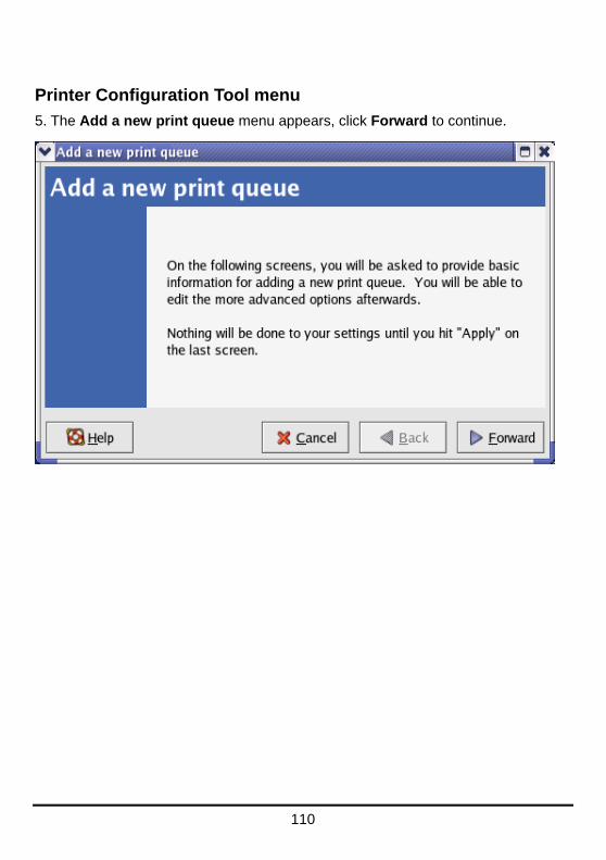
Printer Configuration Tool menu
5. The Add a new print queue menu appears, click Forward to continue.

111
6. Enter a unique name for the printer in the Name text field. The printer name
cannot contain spaces and must begin with a letter. The printer name may contain
letters, numbers, dashes (-), and underscores (_). Optionally, enter a short
description for the printer, which can contain spaces. Then click Forward to enter
Queue type window.
7. Select Networked UNIX (LPD) in the Select a queue type pull down menu,
enter the IP address of the print server to which the printer is attached in Server
field, and type the port name in queue field. Click Forward to select the type of
printer.

112
8. Select the printer model.

113
If a printer has not been detected automatically, select the model from the list. You
can manually select the name of the printer manufacturer from the Generic (click
to select manufacturer) pull-down menu, and the printer model from the sub-list.
Click Forward to continue.
9. The last step is to confirm your printer configuration. Click Apply button to
confirm or Back button to modify the configuration.

114
10. Print a test page to make sure the printer is functioning properly. To print a test
page, select the printer from the printer list, then select the appropriate test page
from the Test drop-down menu.

115
Setting up Printing in Mac OS X Tiger (10.4)
NOTE: Mac OS printing is supported by Postscript printers only!
With Mac OS X Tiger (10.4), you can use Apple Talk, Bonjour, Internet Printing
Protocol (IPP), Line Printer Daemon (LPD), and HP Jet Direct-Socket printing
through Print Server.
Click on this icon in your Dock to open your System
Preferences window as below.
Click on the Network icon in System Preferences menu to view the menu below.
116
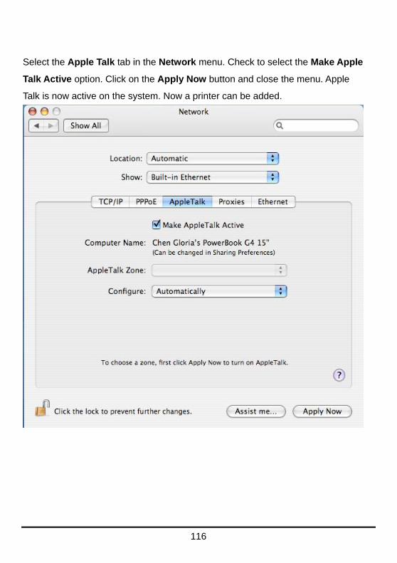
Select the Apple Talk tab in the Network menu. Check to select the Make Apple
Talk Active option. Click on the Apply Now button and close the menu. Apple
Talk is now active on the system. Now a printer can be added.

117
Adding a Printer
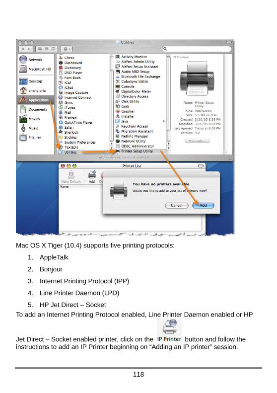
Use the Go menu at the top tool bar and select Applications option and find the
Utilities folder or open the Utilities folder directly in Go menu.
In the Utilities folder, find and select to open Printer
List window. If no printer has been set up on your Macintosh, you will be
prompted to add a printer. Click Add button on the pop-up dialogue box to open
Printer Browser window.
118
Mac OS X Tiger (10.4) supports five printing protocols:
1. AppleTalk
2. Bonjour
3. Internet Printing Protocol (IPP)
4. Line Printer Daemon (LPD)
5. HP Jet Direct – Socket
To add an Internet Printing Protocol enabled, Line Printer Daemon enabled or HP
Jet Direct – Socket enabled printer, click on the button and follow the instructions to add an IP Printer beginning on “Adding an IP printer” session.

119
AppleTalk-enabled or Bonjour-enabled
Printers To add an AppleTalk-enabled or Bonjour-enabled printer, click on the
button in the Printer Browser menu.
Select the printer model from Printer Name list and Connection type in the
Printer Browser menu. The printer name selected should be the same as that
appearing listed in the Printer Server’s web manager. In the example here, the
printer name is dlk-1A2AAA-U1. By default the Printer Browser will use the Auto
Select for Print Using: to determine what printer configuration to use. This may

120
also be manually selected in the Print Using drop-down menu by brand and
model. Click the Add button to exit the Printer Browser window and implement
the new setting.

121
The printer that has just been added will show up in the Printer List menu, it
might take a few seconds depending on network conditions. When the printer
appears listed it is ready for use. Quite the Printer Setup Utility and start printing.

122
Adding an IP Printer
To add an Internet Printing Protocol enabled, Line Printer Daemon enabled or HP
Jet Direct – Socket enabled printer, click on the IP Printer button in the Printer
Browser window. Select the desired printing protocol from the Protocol
drop-down menu.
Type the IP Address of the printer, the name will appear in the Name field when
the printer is found. The Printer Browser will indicate that it is verifying the
address. If the printer is found, the Printer Browser will state “Valid and complete
address” under the Address field.

123
The printer utility is able to detect the printer and may automatically select the
correct printer driver in the Print Using field. Or manually select the printer-maker
from the Print Using drop-down menu, and then select the printer model from the
scroll-down list, or select Generic PostScrip Printer option from the Print Using
drop-down menu if the model is not listed. To implement the setting, click Add
button.
The setup procedures for these three printing protocols (Internet Printing Protocol
(IPP), Line Printer Daemon (LPD), and HP Jet Direct – Socket) are basically the
same. Illustrated examples are include below for the sake of reference.

124
For set up LPD Printing:
1. Enter the IP address of the print server to which the printer is attached in
Address field.
2. Type the port name in queue field.
Click Add button after done the section of printer model in the Print Using
drop-down menu.
125
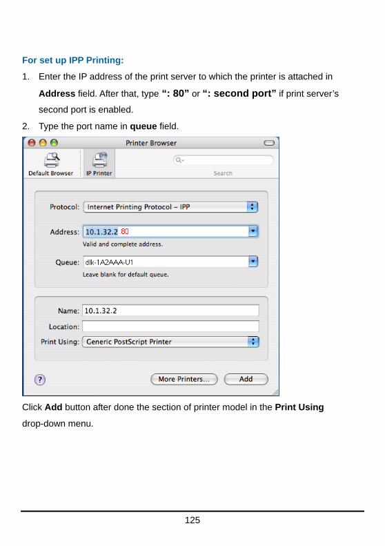
For set up IPP Printing:
1. Enter the IP address of the print server to which the printer is attached in
Address field. After that, type “: 80” or “: second port” if print server’s
second port is enabled.
2. Type the port name in queue field.
Click Add button after done the section of printer model in the Print Using
drop-down menu.

126
For set up Socket Printing:
1. Enter the IP address of the print server to which the printer is attached in
Address field. After that, type “: 9100” for port 1, “: 9101” for port 2 or “:
9102” for port 3.
2. Keep the blank in queue field.
Click Add button after done the section of printer model in the Print Using
drop-down menu.

127
When the Installable Options pop-up window shows up as below, click Continue
button.

128
The printer that has just been added will show up in the Printer List menu, it
might take a few seconds depending on network conditions. When the printer
appears listed it is ready for use. Quite the Printer Setup Utility and start printing.

129
Setting up AppleTalk or LPR Printing in Mac OS X NOTE: Mac OS printing is supported by Postscript printers only!
With Mac OSX you can use AppleTalk or LPR printers using IP protocols for
printing through Print Servers.
Open your System Preferences window and Click Network.
Select the AppleTalk tab in this window and check Make AppleTalk Active.

130
To print, open a document and select File Print from the menu.
Select Edit Printer List from the Printer dialog box.

131
Click Add Printer
Select the printing protocol preferred, AppleTalk or LPR Printers using IP.
In this example, AppleTalk has been selected.

132
AppleTalk protocol: After selecting AppleTalk, the Port Names of the Print Server
will be displayed. The Port Names shown here are examples only. Click on the
Port to which the post-script printer is connected.

133
Then select the printer model from the dialog box displayed here. Click Add
Printer and the Printer Port configuration is completed. Select the Printer Port just
configured in the Print window. Click Print to print your document.
LPR Printers using IP protocol: When you select LPR Printers using IP Protocol,
this window will appear.
Type the IP Address of the Print Server into the LPR Printer‘s Address field.
In the Queue Name field, enter the Port Name of the post-script printer that is
connected to the Print Server. The Port Name illustrated here is only an example.
Select the printer model from the dialog box.
Click Add and the process are completed.
Close all Print Center windows, select the Printer Port that was just selected.
Click Print to print the document.
134
Setting up AppleTalk Printing in Mac OS 9 NOTE: Mac OS printing is supported by Postscript printers only!
The AppleTalk network protocol is used with computers using the MacOS
operating system. It can be used for network communications over standard
Ethernet or Fast Ethernet using the EtherTalk transport, or over a proprietary
low-speed LocalTalk transport.
Print server can be used for network printing to PostScript printers. You can print
from any MacOS computer connected to your Ethernet network, either directly
using an EtherTalk connection, or indirectly through a LocalTalk-to-EtherTalk
router.
NOTE: The Chooser name of a printer connected to one of the Print Server‘s
ports is the same as its Port Name. If you are using AppleTalk printing, you
will need to make sure that every Port Name is unique among all of the
network printers in your AppleTalk zone. The Port Names shown in this
manual are examples only.
To set up print server so that it can be used for AppleTalk printing:
Make sure the AppleTalk protocol is enabled in your Macintosh.
Make sure the PC’s IP Address must correspond with the Print Server’s IP
Address in the same segment for the two devices to communicate.
Launch the browser and enter print server web interface, select the ADVANCED
tab, click Advanced LAN button and then scroll to the bottom to the AppleTalk
protocol section

135
If your AppleTalk network is divided into AppleTalk zones, you will have to specify
which zone the Print Server should be in. You should locate the Print Server in the
same zone as most of the users who will be using it. If your network is not divided
into zones, the AppleTalk Zone field should contain a single asterisk (*).
For each Printer Port that will be used for AppleTalk printing, you may need to
change the AppleTalk Port Settings in the Advanced LAN screen, shown as below.
136
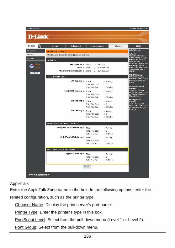
AppleTalk
Enter the AppleTalk Zone name in the box. In the following options, enter the
related configuration, such as the printer type.
Chooser Name: Display the print server's port name.
Printer Type: Enter the printer's type in this box.
PostScript Level: Select from the pull-down menu (Level 1 or Level 2).
Font Group: Select from the pull-down menu.

137
The exact procedure for selecting a PostScript printer connected to print server may
vary slightly, depending on what printer driver version you are using. The procedure
described below assumes you are using the LaserWriter 8.
To choose a printer connected to print server as your MacOS workstation‘s default
printer, open the Chooser by selecting Chooser from the Apple menu. Select the
LaserWriter 8 icon on the left. Make sure that AppleTalk is set to Active.
A list of all networked PostScript printers will be displayed as follow.
Double-click the name of the Printer Port you wish to use. The Printer Ports shown
are examples only.

138
If you have not previously set this printer as the default, your computer will prompt
you for a PostScript Printer Description file. Choose Select PPD.
Select the appropriate printer description file for your printer.
Click Open. (If your printer is not listed, click Generic to use a generic printer description.)
If you wish to access this setting in the future, you can use the Setup button in the Chooser window.
The selected printer will become your computer‘s default printer. You may need to choose Page Setup in any applications you have open.

139
Technical Specifications
Printer Connection Printer Port: USB port
Bi-directional Communication: Hewlett-Packard PJL (Printer Job Language)
standard for bi-directional communication.
Network Connection Network Standards: 100Base-TX Fast Ethernet
Network Data Transfer Rate: 10/100 Mbps (megabits per second)
Network Connector: RJ-45
Network Protocols Ethernet Frame Types: 802.2, 802.3, Ethernet II, SNAP (auto-switching)
Transport Protocols: TCP/IP, NetBEUI, AppleTalk/EtherTalk, LPR,SMB
TCP/IP Protocols Supported: BOOTP, SNMP, FTP, LPD, RARP, DHCP, IPP
Management and Diagnostics Standard: SNMP
MIBs: MIB-II (RFC 1213)
Diagnostic LED Indicators: Power, USB, LAN
Environmental and Physical Power Supply: External power supply providing 5V, 2.5A DC
Dimensions: 3.54" x 3.19" x 1.57" (90 mm x 81 mm x 40 mm)
Weight: approx. 4.27 oz. (121g)
Operating Temperature: 32 to122°F (0 to 50°C)
Storage Temperature: -13 to 131°F (-25 to 55°C)
Humidity: 5% to 95% non-condensing
Emissions: FCC Class B, CE Class B, VCCI Class B
140
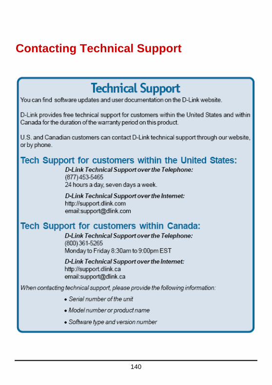
Contacting Technical Support

141
Warranty and Registration Subject to the terms and conditions set forth herein, D-Link Systems, Inc. (—D-Link“) provides this Limited warranty for its product only to the person or entity that originally purchased the product from:
D-Link or its authorized reseller or distributor and Products purchased and delivered within the fifty states of the United States, the District of Columbia, U.S. Possessions or Protectorates, U.S. Military Installations, addresses with an APO or FPO.
Limited Warranty: D-Link warrants that the hardware portion of the D-Link products described below will be free from material defects in workmanship and materials from the date of original retail purchase of the product, for the period set forth below applicable to the product type (—Warranty Period“), except as otherwise stated herein.
1-Year Limited Warranty for the Product(s) is defined as follows:
Hardware (excluding power supplies and fans) One (1) Year
Power Supplies and Fans One (1) Year
Spare parts and spare kits ninety (90) days.
D-Link‘s sole obligation shall be to repair or replace the defective Hardware during the Warranty Period at no charge to the original owner or to refund at D-Link‘s sole discretion. Such repair or replacement will be rendered by D-Link at an Authorized D-Link Service Office. The replacement Hardware need not be new or have an identical make, model or part. D-Link may in its sole discretion replace the defective Hardware (or any part thereof) with any reconditioned product that D-Link reasonably determines is substantially equivalent (or superior) in all material respects to the defective Hardware. Repaired or replacement Hardware will be warranted for the remainder of the original Warranty Period from the date of original retail purchase. If a material defect is incapable of correction, or if D-Link determines in its sole discretion that it is not practical to repair or replace the defective Hardware, the price paid by the original purchaser for the defective Hardware will be refunded by D-Link upon return to D-Link of the defective Hardware. All Hardware (or part thereof) that is replaced by D-Link, or for which the purchase price is refunded, shall become the property of D-Link upon replacement or refund.
Limited Software Warranty: D-Link warrants that the software portion of the product (—Software“) will substantially conform to D-Link‘s then current functional specifications for the Software, as set forth in the applicable documentation, from the date of original retail purchase of the Software for a period of ninety (90)days (—Warranty Period“), provided that the Software is properly installed on approved hardware and operated as contemplated in its documentation. D-Link further warrants that, during the Warranty Period, the magnetic media on which D-Link delivers the Software will be free of physical defects. D-Link‘s sole obligation shall be to replace the non-conforming Software (or defective media) with software that substantially conforms to D-Link‘s functional specifications for the Software or to refund at D-Link‘s sole discretion. Except as otherwise agreed by D-Link in writing, the replacement Software is provided only to the original licensee, and is subject to the terms and conditions of the license granted by D-Link for the Software. Software will be warranted for the remainder of the original Warranty Period from the date or original retail purchase. If a material non-conformance is incapable of correction, or if D-Link determines in its sole discretion that it is not practical to replace the non-conforming Software, the price paid by the original licensee for the non-conforming Software will be refunded by D-Link; provided that the non-conforming Software (and all copies thereof) is first returned to D-Link. The license granted respecting any Software for which a refund is given automatically terminates.
Non-Applicability of Warranty: The Limited Warranty provided hereunder for hardware and software of D-Link‘s products will not be applied to and does not cover any refurbished product and any product

142
purchased through the inventory clearance or liquidation sale or other sales in which D-Link, the sellers, or the liquidators expressly disclaim their warranty obligation pertaining to the product and in that case, the product is being sold —As-Is“ without any warranty whatsoever including, without limitation, the Limited Warranty as described herein, notwithstanding anything stated herein to the contrary.
Submitting A Claim: The customer shall return the product to the original purchase point based on its return policy. In case the return policy period has expired and the product is within warranty, the customer shall submit a claim to D-Link as outlined below:
The customer must submit with the product as part of the claim a written description of the Hardware defect or Software nonconformance in sufficient detail to allow D-Link to confirm the same.
The original product owner must obtain a Return Material Authorization (—RMA“) number from the Authorized D-Link Service Office and, if requested, provide written proof of purchase of the product (such as a copy of the dated purchase invoice for the product) before the warranty service is provided.
After an RMA number is issued, the defective product must be packaged securely in the original or other suitable shipping package to ensure that it will not be damaged in transit, and the RMA number must be prominently marked on the outside of the package. Do not include any manuals or accessories in the shipping package. D-Link will only replace the defective portion of the Product and will not ship back any accessories.
The customer is responsible for all in-bound shipping charges to D-Link. No Cash on Delivery (—COD“) is allowed. Products sent COD will either be rejected by D-Link or become the property of D-Link. Products shall be fully insured by the customer and shipped to D-Link Systems, Inc., 53 Discovery Drive, Irvine, CA 92618. D-Link will not be held responsible for any packages that are lost in transit to D-Link. The repaired or replaced packages will be shipped to the customer via UPS Ground or any common carrier selected by D-Link, with shipping charges prepaid. Expedited shipping is available if shipping charges are prepaid by the customer and upon request.
D-Link may reject or return any product that is not packaged and shipped in strict compliance with the foregoing requirements, or for which an RMA number is not visible from the outside of the package. The product owner agrees to pay D-Link‘s reasonable handling and return shipping charges for any product that is not packaged and shipped in accordance with the foregoing requirements, or that is determined by D-Link not to be defective or non-conforming.
What Is Not Covered: This limited warranty provided by D-Link does not cover: Products, if in D-Link‘s judgment, have been subjected to abuse, accident, alteration, modification, tampering, negligence, misuse, faulty installation, lack of reasonable care, repair or service in any way that is not contemplated in the documentation for the product, or if the model or serial number has been altered, tampered with, defaced or removed; Initial installation, installation and removal of the product for repair, and shipping costs; Operational adjustments covered in the operating manual for the product, and normal maintenance; Damage that occurs in shipment, due to act of God, failures due to power surge, and cosmetic damage; Any hardware, software, firmware or other products or services provided by anyone other than D-Link; Products that have been purchased from inventory clearance or liquidation sales or other sales in which D-Link, the sellers, or the liquidators expressly disclaim their warranty obligation pertaining to the product. Repair by anyone other than D-Link or an Authorized D-Link Service Office will void this Warranty.
Disclaimer of Other Warranties: EXCEPT FOR THE LIMITED WARRANTY SPECIFIED HEREIN, THEPRODUCT IS PROVIDED —AS-IS“ WITHOUT ANY WARRANTY OF ANY KIND WHATSOEVER INCLUDING, WITHOUT LIMITATION, ANY WARRANTY OF MERCHANTABILITY, FITNESS FOR A PARTICULAR PURPOSEAND NON-INFRINGEMENT. IF ANY IMPLIED WARRANTY CANNOT BE DISCLAIMED IN ANYTERRITORY WHERE A PRODUCT IS SOLD, THE DURATION OF SUCH IMPLIED WARRANTY SHALL BE LIMITED TO NINETY (90) DAYS. EXCEPTAS EXPRESSLY

143
COVERED UNDER THE LIMITED WARRANTY PROVIDED HEREIN, THE ENTIRERISK AS TOTHE QUALITY, SELECTION AND PERFORMANCE OF THE PRODUCT IS WITH THE PURCHASER OFTHE PRODUCT.
Limitation of Liability: TO THE MAXIMUM EXTENT PERMITTED BY LAW, D-LINK IS NOT LIABLE UNDERANY CONTRACT, NEGLIGENCE, STRICT LIABILITY OR OTHER LEGAL OR EQUITABLE THEORY FOR ANYLOSS OF USE OF THE PRODUCT, INCONVENIENCE OR DAMAGES OF ANY CHARACTER, WHETHER DIRECT, SPECIAL, INCIDENTAL OR CONSEQUENTIAL (INCLUDING, BUT NOT LIMITED TO, DAMAGES FOR LOSS OFGOODWILL, LOSS OF REVENUE OR PROFIT, WORK STOPPAGE, COMPUTER FAILURE OR MALFUNCTION, FAILURE OF OTHER EQUIPMENT OR COMPUTER PROGRAMS TO WHICH D-LINK‘S PRODUCT IS CONNECTEDWITH, LOSS OF INFORMATION OR DATA CONTAINED IN, STORED ON, OR INTEGRATED WITH ANY PRODUCTRETURNED TO D-LINK FOR WARRANTY SERVICE) RESULTING FROM THE USE OF THE PRODUCT, RELATINGTO WARRANTYSERVICE, OR ARISING OUT OFANY BREACH OF THIS LIMITED WARRANTY, EVEN IF D-LINKHAS BEEN ADVISED OF THE POSSIBILITY OF SUCH DAMAGES. THE SOLE REMEDY FOR A BREACH OF THE FOREGOING LIMITED WARRANTY IS REPAIR, REPLACEMENT OR REFUND OF THE DEFECTIVE OR NON-CONFORMING PRODUCT. THE MAXIMUM LIABILITY OF D-LINK UNDER THIS WARRANTY IS LIMITED TO THE PURCHASE PRICE OF THE PRODUCT COVERED BYTHE WARRANTY.THE FOREGOING EXPRESS WRITTEN WARRANTIES AND REMEDIES ARE EXCLUSIVE AND ARE IN LIEU OF ANY OTHER WARRANTIES OR REMEDIES, EXPRESS, IMPLIED OR STATUTORY.
Governing Law: This Limited Warranty shall be governed by the laws of the State of California. Some states do not allow exclusion or limitation of incidental or consequential damages, or limitations on how long an implied warranty lasts, so the foregoing limitations and exclusions may not apply. This limited warranty provides specific legal rights and the product owner may also have other rights which vary from state to state.
Trademarks: D-Link is a registered trademark of D-Link Systems, Inc. Other trademarks or registered trademarks are the property of their respective manufacturers or owners.
Copyright Statement: No part of this publication or documentation accompanying this Product may be reproduced in any form or by any means or used to make any derivative such as translation, transformation, or adaptation without permission from D-Link Corporation/D-Link Systems, Inc., as stipulated by the United States Copyright Act of 1976. Contents are subject to change without prior
notice. Copyright© 2002 by D-Link Corporation/ D-Link Systems, Inc. All rights reserved.
CE Mark Warning: This is a Class B product. In a domestic environment, this product may cause radio interference, in which case the user may be required to take adequate measures.
FCC Statement: This equipment has been tested and found to comply with the limits for a Class B digital device, pursuant to part 15 of the FCC Rules. These limits are designed to provide reasonable protection against harmful interference in a residential installation. This equipment generates, uses, and can radiate radiofrequency energy and, if not installed and used in accordance with the instructions, may cause harmful interference to radio communication. However, there is no guarantee that interference will not occur in a particular installation. If this equipment does cause harmful interference to radio or television reception, which can be determined by turning the equipment off and on, the user is encouraged to try to correct the interference by one or more of the following measures:
Reorient or relocate the receiving antenna.
Increase the separation between the equipment and receiver.
Connect the equipment into an outlet on a circuit different from that to which the receiver is connected.
Consult the dealer or an experienced radio/TV technician for help.
144
FCC Caution: Any changes or modifications not expressly approved by the party responsible for compliance could void the user‘s authority to operate this equipment.
This device complies with Part 15 of the FCC Rules. Operation is subject to the following two conditions: (1) This device may not cause harmful interference, and (2) this device must accept any interference received, including interference that may cause undesired operation.
IMPORTANT NOTE: FCC Radiation Exposure Statement:
This equipment complies with FCC radiation exposure limits set forth for an uncontrolled environment. This equipment should be installed and operated with a minimum distance of about 8 inches (20 cm) between the radiator and your body.
This transmitter must not be co-located or operated in conjunction with any other antenna or transmitter.
145
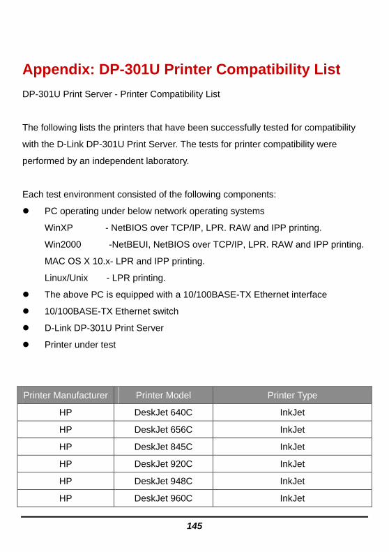
Appendix: DP-301U Printer Compatibility List
DP-301U Print Server - Printer Compatibility List
The following lists the printers that have been successfully tested for compatibility
with the D-Link DP-301U Print Server. The tests for printer compatibility were
performed by an independent laboratory.
Each test environment consisted of the following components:
PC operating under below network operating systems
WinXP - NetBIOS over TCP/IP, LPR. RAW and IPP printing.
Win2000 -NetBEUI, NetBIOS over TCP/IP, LPR. RAW and IPP printing.
MAC OS X 10.x- LPR and IPP printing.
Linux/Unix - LPR printing.
The above PC is equipped with a 10/100BASE-TX Ethernet interface
10/100BASE-TX Ethernet switch
D-Link DP-301U Print Server
Printer under test
Printer Manufacturer Printer Model Printer Type
HP DeskJet 640C InkJet
HP DeskJet 656C InkJet
HP DeskJet 845C InkJet
HP DeskJet 920C InkJet
HP DeskJet 948C InkJet
HP DeskJet 960C InkJet

146
HP DeskJet 90CXI InkJet
HP DeskJet 995C InkJet
HP DeskJet 125C InkJet
HP DeskJet 3320 InkJet
HP DeskJet 3420 InkJet
HP DeskJet 3425 InkJet
HP DeskJet 3535 InkJet
HP DeskJet 3650 InkJet
HP DeskJet 5625 InkJet
HP DeskJet 3745 InkJet
HP DeskJet 3845 InkJet
HP DeskJet 940C InkJet
HP DeskJet 5610 InkJet
HP DeskJet 5650 InkJet
HP DeskJet 5850 InkJet
HP CP 1700 InkJet
HP Business InkJet 1000 InkJet
HP LaserJet 1200 Laser
HP LaserJet 2200 Laser
HP LaserJet 2200D Laser
HP LaserJet 2300D Laser
HP LaserJet 9000 Laser
HP LaserJet 4600PS Laser
HP LaserJet 1000 Laser
HP LaserJet 1010 Laser
HP LaserJet 1020 Laser

147
HP LaserJet 1022 Laser
HP LaserJet 1160 Laser
HP Color LserJet 2600N Laser
HP Color LserJet 3550 Laser
EPSON LP-9100 Laser
EPSON LP-9400 Laser
EPSON LP-9500C Laser
EPSON LP-9800C Laser
EPSON LP-S5500 Laser
EPSON LP-9200B Laser
EPSON LP-9200C Laser
EPSON LP-V500 Laser
EPSON LP-4600PS Laser
EPSON LP-V1000 Laser
EPSON LP-8800CPS Laser
EPSON LP-9800CPL Laser
EPSON LP-9200CPL Laser
EPSON LP-9100PS3 Laser
EPSON EPL-6200 Laser
EPSON PM-G730 Inkjet
EPSON PM-D800 Inkjet
EPSON PM-D600 Inkjet
EPSON TM-T88III POS receipt printer Thermal line
CANON S100SP InkJet
CANON S200SP InkJet
CANON S300 InkJet

148
CANON S330 InkJet
CANON S400SP InkJet
CANON S520 InkJet
CANON S600 InkJet
CANON S6300 InkJet
CANON S750 InkJet
CANON S450 InkJet
CANON S4500 InkJet
CANON S9000 InkJet
CANON PIXUS 850i InkJet
CANON BJC55 InkJet
CANON BJC85 InkJet
CANON I850 InkJet
CANON IP1000 InkJet
CANON IP3000 InkJet
CANON IP4000 InkJet
Lexmark Z13 InkJet
Lexmark Z33 InkJet
Lexmark Z43 InkJet
Lexmark Z53 InkJet
Lexmark Z25 InkJet
Lexmark Z35 InkJet
Lexmark Z45 InkJet
Lexmark Z615 InkJet
Lexmark Z810 InkJet
Lexmark Z818 InkJet

149
Lexmark Optra Color 45 InkJet
Lexmark Optra C710 InkJet
Lexmark Optra E InkJet
Lexmark Optra E+ InkJet
Lexmark E310 InkJet
Lexmark E230 InkJet
Lexmark Optra K1220 InkJet
Lexmark Optra M410 InkJet
Lexmark Optra M412 InkJet
Lexmark Optra N InkJet
Lexmark Optra R+ InkJet
Lexmark Optra S1250 InkJet
Lexmark Optra S1855 InkJet
Lexmark Optra SC-1275 InkJet
Lexmark Optra SE-3455 InkJet
Lexmark OptraT614 InkJet
Lexmark Optra W810 InkJet
FUJITSU PHASER 3121 Laser
KYOCERA FS-1920 Laser
SAMSUNG ML-1520 Laser