Embed Size (px)
Citation preview
130 131
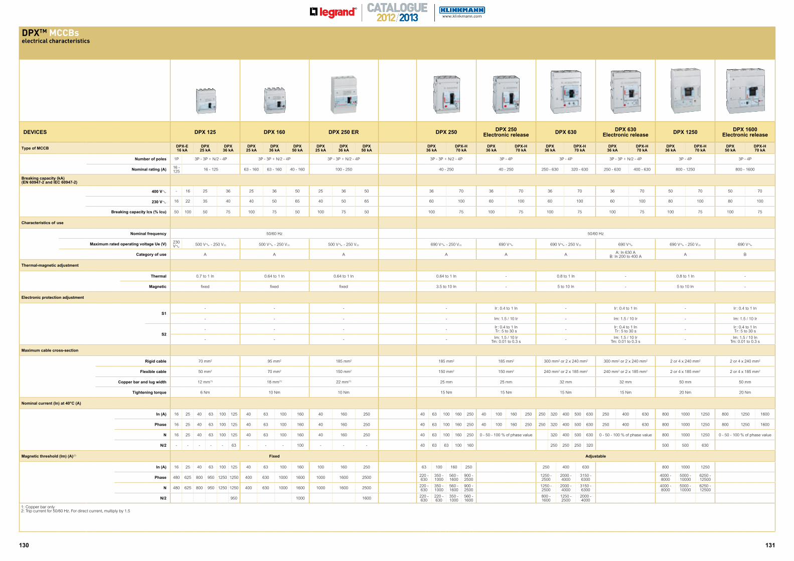
D TM MCCBselectrical characteristics
DEVICES DPX 125 DPX 160 DPX 250 ER DPX 250 DPX 250Electronic release DPX 630 DPX 630
Electronic release DPX 1250 DPX 1600Electronic release
Type of MCCB DPX-E 16 kA
DPX 25 kA
DPX 36 kA
DPX 25 kA
DPX 36 kA
DPX 50 kA
DPX 25 kA
DPX 36 kA
DPX 50 kA
DPX 36 kA
DPX-H 70 kA
DPX 36 kA
DPX-H 70 kA
DPX 36 kA
DPX-H 70 kA
DPX 36 kA
DPX-H 70 kA
DPX 36 kA
DPX-H 70 kA
DPX 50 kA
DPX-H 70 kA
Number of poles 1P 3P - 3P + N/2 - 4P 3P - 3P + N/2 - 4P 3P - 3P + N/2 - 4P 3P - 3P + N/2 - 4P 3P - 4P 3P - 4P 3P - 3P + N/2 - 4P 3P - 4P 3P - 4P
Nominal rating (A) 16 - 125 16 - 125 63 - 160 63 - 160 40 - 160 100 - 250 40 - 250 40 - 250 250 - 630 320 - 630 250 - 630 400 - 630 800 - 1250 800 - 1600
Breaking capacity (kA)(EN 60947-2 and IEC 60947-2)
400 V± - 16 25 36 25 36 50 25 36 50 36 70 36 70 36 70 36 70 50 70 50 70
230 V± 16 22 35 40 40 50 65 40 50 65 60 100 60 100 60 100 60 100 80 100 80 100
Breaking capacity Ics (% Icu) 50 100 50 75 100 75 50 100 75 50 100 75 100 75 100 75 100 75 100 75 100 75
Characteristics of use
Nominal frequency 50/60 Hz 50/60 Hz
Maximum rated operating voltage Ue (V) 230 V± 500 V± - 250 V= 500 V± - 250 V= 500 V± - 250 V= 690 V± - 250 V= 690 V± 690 V± - 250 V= 690 V± 690 V± - 250 V= 690 V±
Category of use A A A A A A A: In 630 A B: In 200 to 400 A A B
Thermal-magnetic adjustment
Thermal 0.7 to 1 In 0.64 to 1 In 0.64 to 1 In 0.64 to 1 In - 0.8 to 1 In - 0.8 to 1 In -
Magnetic fixed fixed fixed 3.5 to 10 In - 5 to 10 In - 5 to 10 In -
Electronic protection adjustment
S1- - - - Ir : 0.4 to 1 In - Ir : 0.4 to 1 In - Ir : 0.4 to 1 In
- - - - Im: 1.5 / 10 Ir - Im: 1.5 / 10 Ir - Im: 1.5 / 10 Ir
S2- - - - Ir : 0.4 to 1 In
Tr : 5 to 30 s - Ir : 0.4 to 1 InTr : 5 to 30 s - Ir : 0.4 to 1 In
Tr : 5 to 30 s
- - - - Im: 1.5 / 10 Ir Tm: 0.01 to 0.3 s - Im: 1.5 / 10 Ir
Tm: 0.01 to 0.3 s - Im: 1.5 / 10 In Tm: 0.01 to 0.3 s
Maximum cable cross-section
Rigid cable 70 mm2 95 mm2 185 mm2 185 mm2 185 mm2 300 mm2 or 2 x 240 mm2 300 mm2 or 2 x 240 mm2 2 or 4 x 240 mm2 2 or 4 x 240 mm2
Flexible cable 50 mm2 70 mm2 150 mm2 150 mm2 150 mm2 240 mm2 or 2 x 185 mm2 240 mm2 or 2 x 185 mm2 2 or 4 x 185 mm2 2 or 4 x 185 mm2
Copper bar and lug width 12 mm(1) 18 mm(1) 22 mm(1) 25 mm 25 mm 32 mm 32 mm 50 mm 50 mm
Tightening torque 6 Nm 10 Nm 10 Nm 15 Nm 15 Nm 15 Nm 15 Nm 20 Nm 20 Nm
Nominal current (In) at 40°C (A)
In (A) 16 25 40 63 100 125 40 63 100 160 40 160 250 40 63 100 160 250 40 100 160 250 250 320 400 500 630 250 400 630 800 1000 1250 800 1250 1600
Phase 16 25 40 63 100 125 40 63 100 160 40 160 250 40 63 100 160 250 40 100 160 250 250 320 400 500 630 250 400 630 800 1000 1250 800 1250 1600
N 16 25 40 63 100 125 40 63 100 160 40 160 250 40 63 100 160 250 0 - 50 - 100 % of phase value 320 400 500 630 0 - 50 - 100 % of phase value 800 1000 1250 0 - 50 - 100 % of phase value
N/2 - - - - - 63 - - - 100 - - - 40 63 63 100 160 250 250 250 320 500 500 630
Magnetic threshold (Im) (A)(2) Fixed Adjustable
In (A) 16 25 40 63 100 125 40 63 100 160 100 160 250 63 100 160 250 250 400 630 800 1000 1250
Phase 480 625 800 950 1250 1250 400 630 1000 1600 1000 1600 2500 220 - 630
350 - 1000
560 - 1600
900 - 2500
1250 - 2500
2000 - 4000
3150 - 6300
4000 - 8000
5000 - 10000
6250 - 12500
N 480 625 800 950 1250 1250 400 630 1000 1600 1000 1600 2500 220 - 630
350 - 1000
560 - 1600
900 - 2500
1250 - 2500
2000 - 4000
3150 - 6300
4000 - 8000
5000 - 10000
6250 - 12500
N/2 950 1000 1600 220 - 630
220 - 630
350 - 1000
560 - 1600
800 - 1600
1250 - 2500
2000 - 4000
1: Copper bar only2: Trip current for 50/60 Hz. For direct current, multiply by 1.5
132
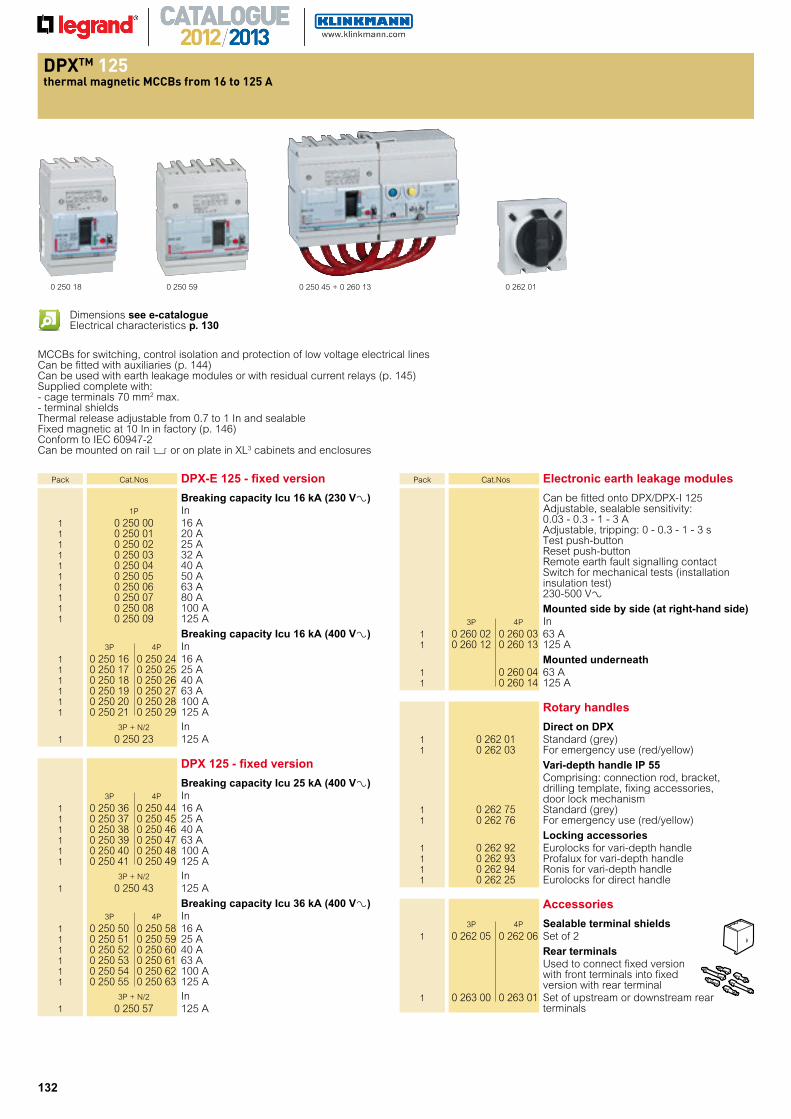
t ermal magnetic s rom to
0 250 18 0 250 45 + 0 260 13
MCCBs for switching, control isolation and protection of low voltage electrical linesCan be fitted with auxiliaries (p. 144)Can be used with earth leakage modules or with residual current relays (p. 145)Supplied complete with:- cage terminals 70 mm2 max.- terminal shieldsThermal release adjustable from 0.7 to 1 In and sealableFixed magnetic at 10 In in factory (p. 146)Conform to IEC 60947-2Can be mounted on rail 2 or on plate in XL3 cabinets and enclosures
Pack Cat.Nos DPX-E 125 - fixed version
Breaking capacity Icu 16 kA (230 V±) 1P In 1 0 250 00 16 A 1 0 250 01 20 A 1 0 250 02 25 A 1 0 250 03 32 A 1 0 250 04 40 A 1 0 250 05 50 A 1 0 250 06 63 A 1 0 250 07 80 A 1 0 250 08 100 A 1 0 250 09 125 A
Breaking capacity Icu 16 kA (400 V±) 3P 4P In 1 0 250 16 0 250 24 16 A 1 0 250 17 0 250 25 25 A 1 0 250 18 0 250 26 40 A 1 0 250 19 0 250 27 63 A 1 0 250 20 0 250 28 100 A 1 0 250 21 0 250 29 125 A 3P + N/2 In 1 0 250 23 125 A
DPX 125 - fixed version
Breaking capacity Icu 25 kA (400 V±) 3P 4P In 1 0 250 36 0 250 44 16 A 1 0 250 37 0 250 45 25 A 1 0 250 38 0 250 46 40 A 1 0 250 39 0 250 47 63 A 1 0 250 40 0 250 48 100 A 1 0 250 41 0 250 49 125 A 3P + N/2 In 1 0 250 43 125 A
Breaking capacity Icu 36 kA (400 V±) 3P 4P In 1 0 250 50 0 250 58 16 A 1 0 250 51 0 250 59 25 A 1 0 250 52 0 250 60 40 A 1 0 250 53 0 250 61 63 A 1 0 250 54 0 250 62 100 A 1 0 250 55 0 250 63 125 A 3P + N/2 In 1 0 250 57 125 A
Pack Cat.Nos Electronic earth leakage modules
Can be fitted onto DPX/DPX-I 125 Adjustable, sealable sensitivity: 0.03 - 0.3 - 1 - 3 A Adjustable, tripping: 0 - 0.3 - 1 - 3 s Test push-button Reset push-button Remote earth fault signalling contact Switch for mechanical tests (installation insulation test) 230-500 V±
Mounted side by side (at right-hand side) 3P 4P In 1 0 260 02 0 260 03 63 A 1 0 260 12 0 260 13 125 A
Mounted underneath 1 0 260 04 63 A 1 0 260 14 125 A
Accessories
3P 4P Sealable terminal shields 1 0 262 05 0 262 06 Set of 2
Rear terminals Used to connect fixed version
with front terminals into fixed version with rear terminal
1 0 263 00 0 263 01 Set of upstream or downstream rear terminals
0 250 59 0 262 01
Rotary handles
Direct on DPX 1 0 262 01 Standard (grey) 1 0 262 03 For emergency use (red/yellow)
Vari-depth handle IP 55 Comprising: connection rod, bracket,
drilling template, fixing accessories, door lock mechanism
1 0 262 75 Standard (grey) 1 0 262 76 For emergency use (red/yellow)
Locking accessories 1 0 262 92 Eurolocks for vari-depth handle 1 0 262 93 Profalux for vari-depth handle 1 0 262 94 Ronis for vari-depth handle 1 0 262 25 Eurolocks for direct handle
Dimensions see e-catalogueElectrical characteristics p. 130
133
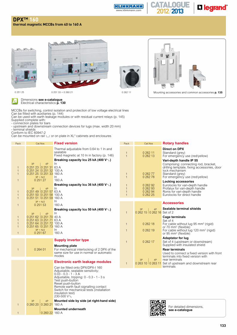
t ermal magnetic s rom to
0 251 33 + 0 260 210 251 25 0 262 11
Accessories
3P 4P Sealable terminal shields 1 0 262 15 0 262 16 Set of 2
Cage terminals Set of 4 1 0 262 18 For cable without lug 95 mm2 (rigid)
or 70 mm2 (flexible) 1 0 262 19 For cable without lug 120 mm2 (rigid)
or 95 mm2 (flexible)
Adaptator for lug 1 0 262 17 Set of 4 (upstream or downstream) Supplied with insulated shield
Rear terminals Used to connect a fixed version with front
terminals into fixed version with 3P 4P rear terminals 1 0 263 10 0 263 11 Set of upstream and downstream rear
terminals
MCCBs for switching, control isolation and protection of low voltage electrical linesCan be fitted with auxiliaries (p. 144)Can be used with earth leakage modules or with residual current relays (p. 145)Supplied complete with:- connection plates for bars- upstream and downstream connection devices for lugs (max. width 20 mm)- terminal shieldsConform to IEC 60947-2Can be mounted on rail 2 or on plate in XL3 cabinets and enclosures
Pack Cat.Nos Fixed version
Thermal adjustable from 0.64 to 1 In and sealable Fixed magnetic at 10 In in factory (p. 146)
Breaking capacity Icu 25 kA (400 V±) 3P 4P In 1 0 251 23 0 251 31 63 A 1 0 251 24 0 251 32 100 A 1 0 251 25 0 251 33 160 A 3P + N/2 In 1 0 251 27 160 A
Breaking capacity Icu 36 kA (400 V±) 3P 4P In 1 0 251 49 0 251 57 63 A 1 0 251 50 0 251 58 100 A 1 0 251 51 0 251 59 160 A 3P + N/2 In 1 0 251 53 160 A
Breaking capacity Icu 50 kA (400 V±) 3P 4P In 1 0 251 62 0 251 70 40 A 1 0 251 63 0 251 71 63 A 1 0 251 64 0 251 72 100 A 1 0 251 65 0 251 73 160 A 3P + N/2 In 1 0 251 67 160 A
Supply invertor type
Mounting plate 1 0 264 01 For mechanical interlocking of 2 DPX of the
same size for use in normal or automatic modes
Electronic earth leakage modules
Can be fitted onto DPX/DPX-I 160 Adjustable, sealable sensitivity:
0.03 - 0.3 - 1 - 3 A Adjustable, tripping: 0 - 0.3 - 1 - 3 s Test push-button Reset push-button Remote earth fault signalling contact Switch for mechanical tests (installation insulation test) 230-500 V±
3P 4P Mounted side by side (at right-hand side) 1 0 260 20 0 260 21 160 A
Mounted underneath 1 0 260 22 160 A
Pack Cat.Nos Rotary handles
Direct on DPX 1 0 262 11 Standard (grey) 1 0 262 13 For emergency use (red/yellow)
Vari-depth handle IP 55 Comprising: connecting rod, bracket,
drilling template, fixing accessories, door lock mechanism
1 0 262 77 Standard (grey) 1 0 262 78 For emergency use (red/yellow)
Locking accessories 1 0 262 92 Eurolocks for vari-depth handle 1 0 262 93 Profalux for vari-depth handle 1 0 262 94 Ronis for vari-depth handle 1 0 262 25 Eurolocks for direct handle
Dimensions see e-catalogueElectrical characteristics p. 130
Mounting accessories and common accessories p. 135
For detailed dimensions, see e-catalogue
134
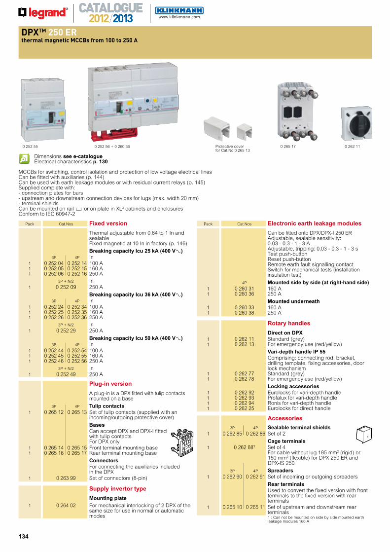
t ermal magnetic s rom to
0 252 56 + 0 260 360 252 55 0 262 11Protective cover for Cat.No 0 265 13
0 265 17
MCCBs for switching, control isolation and protection of low voltage electrical linesCan be fitted with auxiliaries (p. 144)Can be used with earth leakage modules or with residual current relays (p. 145)Supplied complete with:- connection plates for bars- upstream and downstream connection devices for lugs (max. width 20 mm)- terminal shieldsCan be mounted on rail 2 or on plate in XL3 cabinets and enclosures Conform to IEC 60947-2
Pack Cat.Nos Fixed version
Thermal adjustable from 0.64 to 1 In and sealable Fixed magnetic at 10 In in factory (p. 146)
Breaking capacity Icu 25 kA (400 V±) 3P 4P In 1 0 252 04 0 252 14 100 A 1 0 252 05 0 252 15 160 A 1 0 252 06 0 252 16 250 A 3P + N/2 In 1 0 252 09 250 A
Breaking capacity Icu 36 kA (400 V±) 3P 4P In 1 0 252 24 0 252 34 100 A 1 0 252 25 0 252 35 160 A 1 0 252 26 0 252 36 250 A 3P + N/2 In 1 0 252 29 250 A
Breaking capacity Icu 50 kA (400 V±) 3P 4P In 1 0 252 44 0 252 54 100 A 1 0 252 45 0 252 55 160 A 1 0 252 46 0 252 56 250 A 3P + N/2 In 1 0 252 49 250 A
Plug-in version
A plug-in is a DPX fitted with tulip contacts mounted on a base
3P 4P Tulip contacts 1 0 265 12 0 265 13 Set of tulip contacts (supplied with an
incoming/outgoing protective cover)
Bases Can accept DPX and DPX-I fitted
with tulip contacts For DPX only
1 0 265 14 0 265 15 Front terminal mounting base 1 0 265 16 0 265 17 Rear terminal mounting base
Connectors For connecting the auxiliaries included in the DPX 1 0 263 99 Set of connectors (8-pin)
Supply invertor type
Mounting plate 1 0 264 02 For mechanical interlocking of 2 DPX of the
same size for use in normal or automatic modes
Pack Cat.Nos Electronic earth leakage modules
Can be fitted onto DPX/DPX-I 250 ER Adjustable, sealable sensitivity:
0.03 - 0.3 - 1 - 3 A Adjustable, tripping: 0.03 - 0.3 - 1 - 3 s
Test push-button Reset push-button
Remote earth fault signalling contact Switch for mechanical tests (installation
insulation test)
4P Mounted side by side (at right-hand side) 1 0 260 31 160 A 1 0 260 36 250 A
Mounted underneath 1 0 260 33 160 A 1 0 260 38 250 A
Rotary handles
Direct on DPX 1 0 262 11 Standard (grey) 1 0 262 13 For emergency use (red/yellow)
Vari-depth handle IP 55 Comprising: connecting rod, bracket,
drilling template, fixing accessories, door lock mechanism
1 0 262 77 Standard (grey) 1 0 262 78 For emergency use (red/yellow)
Locking accessories 1 0 262 92 Eurolocks for vari-depth handle 1 0 262 93 Profalux for vari-depth handle 1 0 262 94 Ronis for vari-depth handle 1 0 262 25 Eurolocks for direct handle
Accessories
3P 4P Sealable terminal shields 1 0 262 85 0 262 86 Set of 2
Cage terminals 1 0 262 881 Set of 4 For cable without lug 185 mm2 (rigid) or
150 mm2 (flexible) for DPX 250 ER and DPX-IS 250
3P 4P Spreaders 1 0 262 90 0 262 91 Set of incoming or outgoing spreaders
Rear terminals Used to convert the fixed version with front
terminals to the fixed version with rear terminals
1 0 265 10 0 265 11 Set of upstream and downstream rear terminals1 : Can not be mounted on side by side mounted earth leakage modules 160 A
Dimensions see e-catalogueElectrical characteristics p. 130
135
and connection
and mounting accessories
0 048 670 262 08 0 048 68 0 262 00
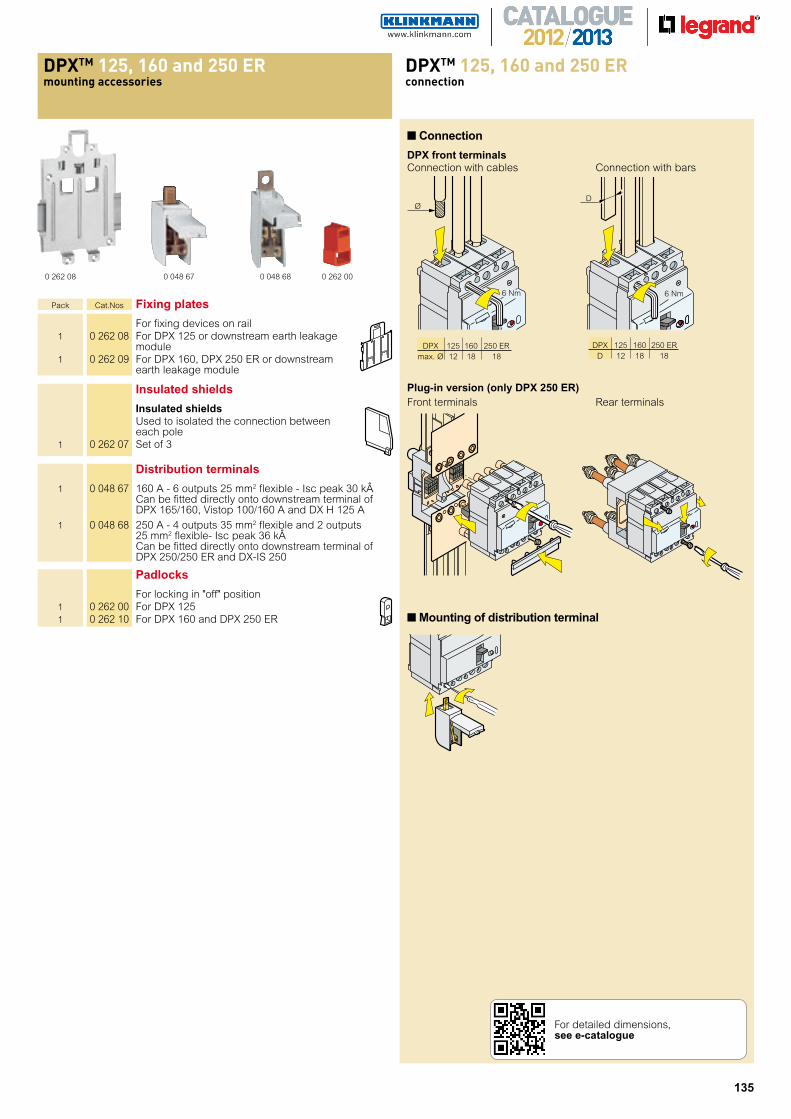
Pack Cat.Nos Fixing plates
For fixing devices on rail 1 0 262 08 For DPX 125 or downstream earth leakage
module 1 0 262 09 For DPX 160, DPX 250 ER or downstream
earth leakage module
Padlocks
For locking in "off" position 1 0 262 00 For DPX 125 1 0 262 10 For DPX 160 and DPX 250 ER
Insulated shields
Insulated shields Used to isolated the connection between
each pole 1 0 262 07 Set of 3
Distribution terminals
1 0 048 67 160 A - 6 outputs 25 mm2 flexible - Isc peak 30 k Can be fitted directly onto downstream terminal of DPX 165/160, Vistop 100/160 A and DX H 125 A
1 0 048 68 250 A - 4 outputs 35 mm2 flexible and 2 outputs 25 mm2 flexible- Isc peak 36 k Can be fitted directly onto downstream terminal of DPX 250/250 ER and DX-IS 250
■Connection
DPX front terminalsConnection with cables Connection with bars
6 Nm
Ø
Plug-in version (only DPX 250 ER)Front terminals Rear terminals
6 Nm
D
■Mounting of distribution terminal
DPX 125 160 250 ER max. Ø 12 18 18
DPX 125 160 250 ER D 12 18 18
For detailed dimensions, see e-catalogue
136
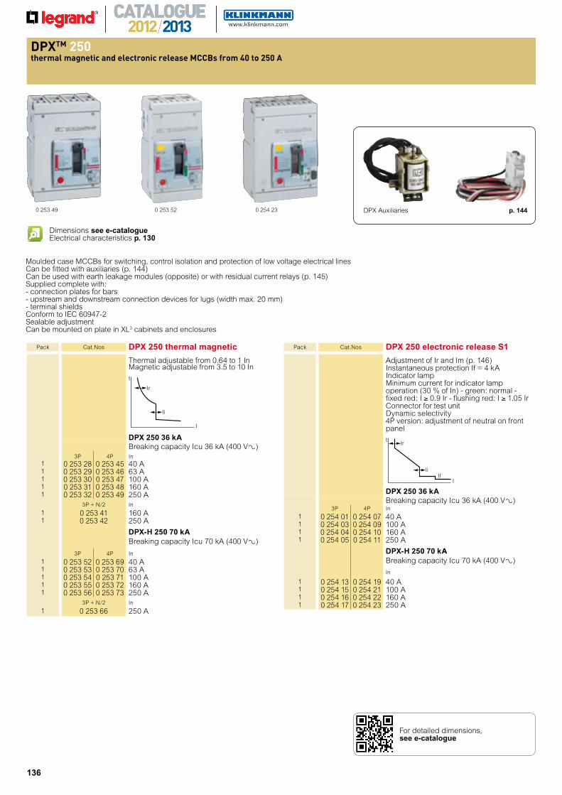
t ermal magnetic and electronic release s rom to
0 253 49 0 253 52 0 254 23
Moulded case MCCBs for switching, control isolation and protection of low voltage electrical linesCan be fitted with auxiliaries (p. 144)Can be used with earth leakage modules (opposite) or with residual current relays (p. 145)Supplied complete with:- connection plates for bars- upstream and downstream connection devices for lugs (width max. 20 mm)- terminal shields Conform to IEC 60947-2Sealable adjustmentCan be mounted on plate in XL3 cabinets and enclosures
Dimensions see e-catalogueElectrical characteristics p. 130
DPX Auxiliaries p. 144
Pack Cat.Nos DPX 250 electronic release S1
Adjustment of Ir and Im (p. 146)Instantaneous protection If = 4 kAIndicator lampMinimum current for indicator lamp operation (30 % of In) - green: normal - fixed red: I ≥ 0.9 Ir - flushing red: I ≥ 1.05 IrConnector for test unitDynamic selectivity4P version: adjustment of neutral on front panel
IiIf
Ir t
I
DPX 250 36 kABreaking capacity Icu 36 kA (400 V±)
3P 4P In
1 0 254 01 0 254 07 40 A1 0 254 03 0 254 09 100 A1 0 254 04 0 254 10 160 A1 0 254 05 0 254 11 250 A
DPX-H 250 70 kABreaking capacity Icu 70 kA (400 V±)
In
1 0 254 13 0 254 19 40 A1 0 254 15 0 254 21 100 A1 0 254 16 0 254 22 160 A1 0 254 17 0 254 23 250 A
Pack Cat.Nos DPX 250 thermal magnetic
Thermal adjustable from 0.64 to 1 InMagnetic adjustable from 3.5 to 10 In
Ii
Ir
t
I
DPX 250 36 kABreaking capacity Icu 36 kA (400 V±)
3P 4P In1 0 253 28 0 253 45 40 A1 0 253 29 0 253 46 63 A1 0 253 30 0 253 47 100 A1 0 253 31 0 253 48 160 A1 0 253 32 0 253 49 250 A
3P + N/2 In
1 0 253 41 160 A1 0 253 42 250 A
DPX-H 250 70 kABreaking capacity Icu 70 kA (400 V±)
3P 4P In
1 0 253 52 0 253 69 40 A1 0 253 53 0 253 70 63 A1 0 253 54 0 253 71 100 A1 0 253 55 0 253 72 160 A1 0 253 56 0 253 73 250 A
3P + N/2 In
1 0 253 66 250 A
For detailed dimensions, see e-catalogue
137
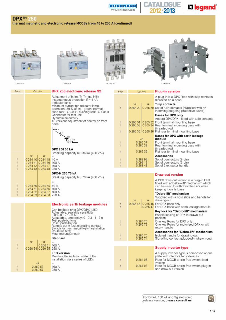
t ermal magnetic and electronic release s rom to continued
0 260 55 0 260 53 0 265 32 0 265 46
Draw-out version
A DPX draw-out version is a plug-in DPX fitted with a "Debro-lift" mechanism which can be used to withdraw the DPX while keeping it on its base
"Debro-lift" mechanism Supplied with a rigid slide and handle for 3P 4P drawing-out 1 0 265 45 0 265 46 For DPX base only 1 0 265 47 For DPX base with earth leakage module
Key lock for "Debro-lift" mechanism Enable locking of DPX in drawn-out
position 1 0 265 76 One key Ronis for DPX only 1 0 265 78 One key Ronis for motorised DPX or with
rotary handle
Accessories for "Debro-lift" mechanism 1 0 265 75 Isolated handle for drawing-out 1 0 265 74 Signalling contact (plugged-in/drawn-out)
Supply invertor type
A supply invertor type is composed of one plate with interlock for 2 devices
1 0 264 08 Plate for MCCB or trip-free switch fixed version
1 0 264 03 Plate for MCCB or trip-free switch plug-in and draw-out version
Pack Cat.Nos Plug-in version
A plug-in is a DPX fitted with tulip contacts mounted on a base
3P 4P Tulip contacts 1 0 265 29 0 265 30 Set of tulip contacts (supplied with an
incoming/outgoing protective cover)
Bases for DPX only Accept DPX/DPX-I fitted with tulip contacts 1 0 265 31 0 265 32 Front terminal mounting base 1 0 265 33 0 265 34 Rear terminal mounting base with
threaded rod 1 0 265 35 0 265 36 Flat rear terminal mounting base
4P
Bases for DPX with earth leakage module
1 0 265 37 Front terminal mounting base 1 0 265 38 Rear terminal mounting base with
threaded rod 1 0 265 39 Flat rear terminal mounting base
Accessories 1 0 263 99 Set of connectors (8-pin) 1 0 098 19 Set of connectors (6-pin) 1 0 263 43 Set of 2 extractor handle
For DPX-L 100 kA and Sg electronic release version, please consult us
Pack Cat.Nos DPX 250 electronic release S2
Adjustment of Ir, Im, Tr, Tm (p. 146)Instantaneous protection If = 4 kAIndicator lampMinimum current for indicator lamp operation (30 % of In) - green: normal - fixed red: I ≥ 0.9 Ir - flushing red: I ≥ 1.05 IrConnector for test unitDynamic selectivity4P version: adjustment of neutral on front panel
IsdTsd
Tr
Irt
I I2t
DPX 250 36 kABreaking capacity Icu 36 kA (400 V±)
3P 4P In
1 0 254 40 0 254 45 40 A1 0 254 41 0 254 46 100 A1 0 254 42 0 254 47 160 A1 0 254 43 0 254 48 250 A
DPX-H 250 70 kABreaking capacity Icu 70 kA (400 V±)
In
1 0 254 50 0 254 55 40 A1 0 254 51 0 254 56 100 A1 0 254 52 0 254 57 160 A1 0 254 53 0 254 58 250 A
Electronic earth leakage modules
Can be fitted onto DPX/DPX-I 250Adjustable, sealable sensitivity:0.03 - 0.3 - 1 - 3 AAdjustable, time delay: 0 - 0.3 - 1 - 3 sTest push-buttonsReset push-buttonRemote earth fault signalling contactSwitch for mechanical tests (installation insulation test) Mounted underneath
Standard3P 4P In
1 0 260 51 160 A1 0 260 54 0 260 55 250 A
LED versionMonitors the isolation state of theinstallation via a series of LEDs
4P In1 0 260 53 160 A1 0 260 57 250 A
138
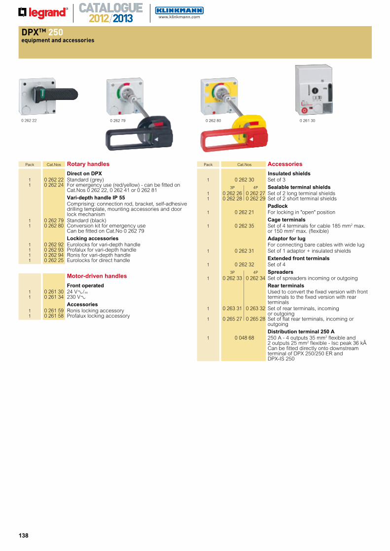
equi ment and accessories
0 262 22 0 262 79 0 262 80 0 261 30
Motor-driven handles
Front operated 1 0 261 30 24 V±/= 1 0 261 34 230 V± Accessories 1 0 261 59 Ronis locking accessory 1 0 261 58 Profalux locking accessory
Pack Cat.Nos Rotary handles
Direct on DPX 1 0 262 22 Standard (grey) 1 0 262 24 For emergency use (red/yellow) - can be fitted on
Cat.Nos 0 262 22, 0 262 41 or 0 262 81
Vari-depth handle IP 55 Comprising: connection rod, bracket, self-adhesive
drilling template, mounting accessories and door lock mechanism
1 0 262 79 Standard (black) 1 0 262 80 Conversion kit for emergency use
Can be fitted on Cat.No 0 262 79
Locking accessories 1 0 262 92 Eurolocks for vari-depth handle 1 0 262 93 Profalux for vari-depth handle 1 0 262 94 Ronis for vari-depth handle 1 0 262 25 Eurolocks for direct handle
Pack Cat.Nos Accessories
Insulated shields 1 0 262 30 Set of 3
3P 4P Sealable terminal shields 1 0 262 26 0 262 27 Set of 2 long terminal shields 1 0 262 28 0 262 29 Set of 2 short terminal shields
Padlock 1 0 262 21 For locking in "open" position
Cage terminals 1 0 262 35 Set of 4 terminals for cable 185 mm2 max.
or 150 mm2 max. (flexible)
Adaptor for lug For connecting bare cables with wide lug 1 0 262 31 Set of 1 adaptor + insulated shields
Extended front terminals 1 0 262 32 Set of 4
3P 4P Spreaders 1 0 262 33 0 262 34 Set of spreaders incoming or outgoing
Rear terminals Used to convert the fixed version with front
terminals to the fixed version with rear terminals
1 0 263 31 0 263 32 Set of rear terminals, incoming or outgoing
1 0 265 27 0 265 28 Set of flat rear terminals, incoming or outgoing
Distribution terminal 250 A 1 0 048 68 250 A - 4 outputs 35 mm2 flexible and
2 outputs 25 mm2 flexible - Isc peak 36 k Can be fitted directly onto downstream terminal of DPX 250/250 ER and DPX-IS 250
139
t ermal magnetic and electronic release s rom to
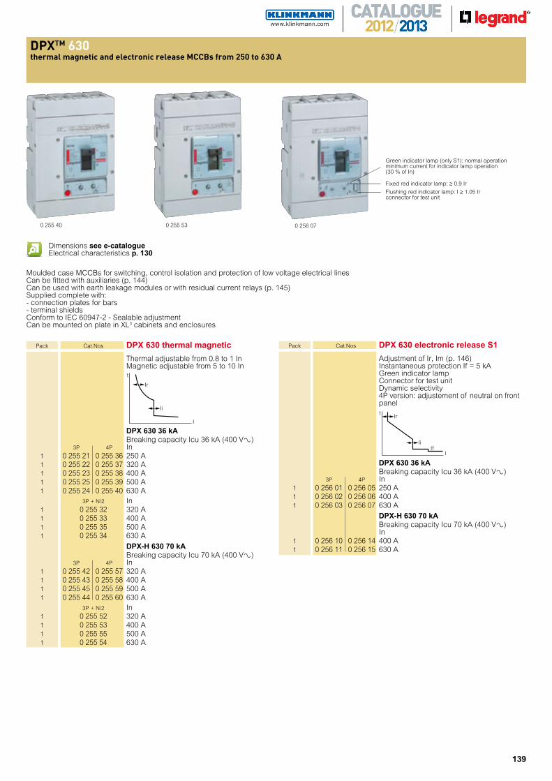
0 255 530 255 40 0 256 07
Green indicator lamp (only S1): normal operation
minimum current for indicator lamp operation (30 % of In)
Fixed red indicator lamp: ≥ 0.9 Ir
Flushing red indicator lamp: I ≥ 1.05 Ir connector for test unit
Moulded case MCCBs for switching, control isolation and protection of low voltage electrical linesCan be fitted with auxiliaries (p. 144)Can be used with earth leakage modules or with residual current relays (p. 145)Supplied complete with:- connection plates for bars- terminal shieldsConform to IEC 60947-2 - Sealable adjustmentCan be mounted on plate in XL3 cabinets and enclosures
Pack Cat.Nos DPX 630 electronic release S1
Adjustment of Ir, Im (p. 146) Instantaneous protection If = 5 kA
Green indicator lamp Connector for test unit Dynamic selectivity 4P version: adjustement of neutral on front panel
DPX 630 36 kA Breaking capacity Icu 36 kA (400 V±) 3P 4P In 1 0 256 01 0 256 05 250 A 1 0 256 02 0 256 06 400 A 1 0 256 03 0 256 07 630 A
DPX-H 630 70 kA Breaking capacity Icu 70 kA (400 V±) In 1 0 256 10 0 256 14 400 A 1 0 256 11 0 256 15 630 A
Pack Cat.Nos DPX 630 thermal magnetic
Thermal adjustable from 0.8 to 1 In Magnetic adjustable from 5 to 10 In
DPX 630 36 kA Breaking capacity Icu 36 kA (400 V±) 3P 4P In 1 0 255 21 0 255 36 250 A 1 0 255 22 0 255 37 320 A 1 0 255 23 0 255 38 400 A 1 0 255 25 0 255 39 500 A 1 0 255 24 0 255 40 630 A 3P + N/2 In 1 0 255 32 320 A 1 0 255 33 400 A 1 0 255 35 500 A 1 0 255 34 630 A
DPX-H 630 70 kA Breaking capacity Icu 70 kA (400 V±) 3P 4P In 1 0 255 42 0 255 57 320 A 1 0 255 43 0 255 58 400 A 1 0 255 45 0 255 59 500 A 1 0 255 44 0 255 60 630 A 3P + N/2 In 1 0 255 52 320 A 1 0 255 53 400 A 1 0 255 55 500 A 1 0 255 54 630 A
Ii
Ir
t
I
IiIf
Ir t
I
Dimensions see e-catalogueElectrical characteristics p. 130
140
t ermal magnetic and electronic release s rom to continued
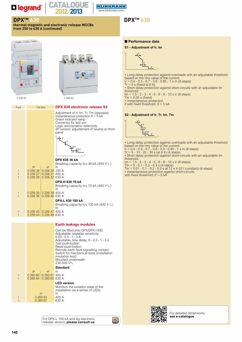
Pack Cat.Nos DPX 630 electronic release S2
Adjustment of Ir, Im, Tr, Tm (opposite) Instantaneous protection If = 5 kA Green indicator lamp Connector for test unit Logic and dynamic selectivity 4P version: adjustement of neutral on front panel
DPX 630 36 kA Breaking capacity Icu 36 kA (400 V±) 3P 4P In 1 0 256 26 0 256 30 250 A 1 0 256 27 0 256 31 400 A 1 0 256 28 0 256 32 630 A
DPX-H 630 70 kA Breaking capacity Icu 70 kA (400 V±) In 1 0 256 35 0 256 39 400 A 1 0 256 36 0 256 40 630 A
DPX-L 630 100 kA Breaking capacity Icu 100 kA (400 V±) In 1 0 256 43 0 256 47 400 A 1 0 256 44 0 256 48 630 A
0 260 630 256 35
IsdTsd
Tr
Irt
I I2t
Earth leakage modules
Can be fitted onto DPX/DPX-I 630 Adjustable, sealable sensitivity:
0.03 - 0.3 - 1 - 3 A Adjustable, time delay: 0 - 0.3 - 1 - 3 s
Test push-button Reset push-button Remote earth fault signalling contact Switch for mechanical tests (installation insulation test)
Mounted underneath 230-500 V±
Standard 3P 4P In 1 0 260 60 0 260 61 400 A 1 0 260 64 0 260 65 630 A
LED version Monitors the isolation state of the
installation via a series of LEDs 4P In 1 0 260 63 400 A 1 0 260 67 630 A
If
Ii
Ir t
I
• based on the rms value of the current:Ir = 0.4 - 0.5 - 0.7 - 0.8 - 0.95 - 1 x In (8 steps)Tr = 5 s (fixed at 6 tr)• threshold:Im = 1.5 - 2 - 3 - 4 - 5 - 6 - 8 - 10 x Ir (8 steps)Tm = 0.05 s (fixed)• if with fixed threshold: If = 5 kA
S2 - Adjustment of Ir, Tr, Im, Tm
If
Im
Tm
Tr
Ir t
I
• based on the rms value of the current:Ir = 0.4 - 0.5 - 0.7 - 0.8 - 0.9 - 0.95 - 1 x In (8 steps)Tr = 5 - 10 - 20 - 30 s (at 6 Ir) (4 steps)• threshold:Im = 1.5 - 2 - 3 - 4 - 5 - 6 - 8 - 10 x Ir (8 steps)Tm = 0 - 0.1 - 0.2 - 0.3 s (4 steps)Tm = 0.01 - 0.1 - 0.2 - 0.3 s at 12 x Ir (I2 t constant) (4 steps)• with fixed threshold: If = 5 kA
■ Performance data
S1 - Adjustment of Ir, Im
For DPX-L 100 kA and Sg electronic release version, please consult us
For detailed dimensions, see e-catalogue
141
equi ment and accessories
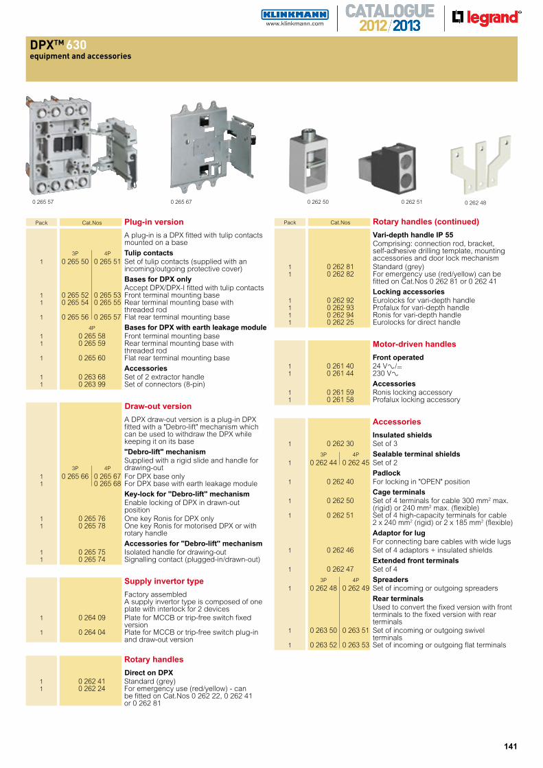
0 265 57 0 265 67 0 262 51 0 262 480 262 50
Pack Cat.Nos Plug-in version
A plug-in is a DPX fitted with tulip contacts mounted on a base
3P 4P Tulip contacts 1 0 265 50 0 265 51 Set of tulip contacts (supplied with an
incoming/outgoing protective cover)
Bases for DPX only Accept DPX/DPX-I fitted with tulip contacts 1 0 265 52 0 265 53 Front terminal mounting base 1 0 265 54 0 265 55 Rear terminal mounting base with
threaded rod 1 0 265 56 0 265 57 Flat rear terminal mounting base
4P Bases for DPX with earth leakage module 1 0 265 58 Front terminal mounting base 1 0 265 59 Rear terminal mounting base with
threaded rod 1 0 265 60 Flat rear terminal mounting base
Accessories 1 0 263 68 Set of 2 extractor handle 1 0 263 99 Set of connectors (8-pin)
Draw-out version
A DPX draw-out version is a plug-in DPX fitted with a "Debro-lift" mechanism which can be used to withdraw the DPX while keeping it on its base
"Debro-lift" mechanism Supplied with a rigid slide and handle for 3P 4P drawing-out 1 0 265 66 0 265 67 For DPX base only 1 0 265 68 For DPX base with earth leakage module
Key-lock for "Debro-lift" mechanism Enable locking of DPX in drawn-out
position 1 0 265 76 One key Ronis for DPX only 1 0 265 78 One key Ronis for motorised DPX or with
rotary handle
Accessories for "Debro-lift" mechanism 1 0 265 75 Isolated handle for drawing-out 1 0 265 74 Signalling contact (plugged-in/drawn-out)
Pack Cat.Nos Rotary handles (continued)
Vari-depth handle IP 55 Comprising: connection rod, bracket,
self-adhesive drilling template, mounting accessories and door lock mechanism
1 0 262 81 Standard (grey) 1 0 262 82 For emergency use (red/yellow) can be
fitted on Cat.Nos 0 262 81 or 0 262 41
Locking accessories 1 0 262 92 Eurolocks for vari-depth handle 1 0 262 93 Profalux for vari-depth handle 1 0 262 94 Ronis for vari-depth handle 1 0 262 25 Eurolocks for direct handle
Accessories
Insulated shields 1 0 262 30 Set of 3
3P 4P Sealable terminal shields 1 0 262 44 0 262 45 Set of 2
Padlock 1 0 262 40 For locking in "OPEN" position
Cage terminals 1 0 262 50 Set of 4 terminals for cable 300 mm2 max.
(rigid) or 240 mm2 max. (flexible) 1 0 262 51 Set of 4 high-capacity terminals for cable
2 x 240 mm2 (rigid) or 2 x 185 mm2 (flexible)
Adaptor for lug For connecting bare cables with wide lugs 1 0 262 46 Set of 4 adaptors + insulated shields
Extended front terminals 1 0 262 47 Set of 4
3P 4P Spreaders 1 0 262 48 0 262 49 Set of incoming or outgoing spreaders
Rear terminals Used to convert the fixed version with front
terminals to the fixed version with rear terminals
1 0 263 50 0 263 51 Set of incoming or outgoing swivel terminals
1 0 263 52 0 263 53 Set of incoming or outgoing flat terminals
Motor-driven handles
Front operated 1 0 261 40 24 V±/= 1 0 261 44 230 V± Accessories 1 0 261 59 Ronis locking accessory 1 0 261 58 Profalux locking accessory
Supply invertor type
Factory assembled A supply invertor type is composed of one
plate with interlock for 2 devices 1 0 264 09 Plate for MCCB or trip-free switch fixed
version 1 0 264 04 Plate for MCCB or trip-free switch plug-in
and draw-out version
Rotary handles
Direct on DPX 1 0 262 41 Standard (grey) 1 0 262 24 For emergency use (red/yellow) - can
be fitted on Cat.Nos 0 262 22, 0 262 41 or 0 262 81
142
t ermal magnetic and electronic release s rom to
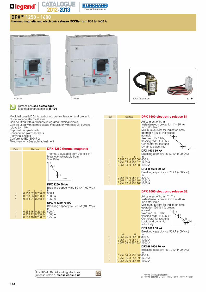
0 258 04 0 257 08
Pack Cat.Nos DPX 1250 thermal magnetic
Thermal adjustable from 0.8 to 1 In Magnetic adjustable from: 5 to 10 In
DPX 1250 50 kA Breaking capacity Icu 50 kA (400 V±) 3P 4P In 1 0 258 02 0 258 091 800 A 1 0 258 03 0 258 101 1000 A 1 0 258 04 0 258 111 1250 A
DPX-H 1250 70 kA Breaking capacity Icu 70 kA (400 V±) In 1 0 258 16 0 258 231 800 A 1 0 258 17 0 258 241 1000 A 1 0 258 18 0 258 251 1250 A
Moulded case MCBs for switching, control isolation and protection of low voltage electrical linesCan be fitted with auxiliaries (integrated terminal blocks)Can be used with earth leakage modules or with residual current relays (p. 145)Supplied complete with:- connection plates for bars- terminal shieldsConform to IEC 60947-2Fixed version - Sealable adjustment
1: Neutral without protection 2: Neutral settings 0 - 0.5 - 1 N (0 - 50% - 100% Neutral)
Ii
Ir
t
I
Pack Cat.Nos DPX 1600 electronic release S1
Adjustment of Ir, Im Instantaneous protection If = 20 kA Indicator lamp Minimum current for indicator lamp operation (30 % In): green: normal; fixed red: I ≥ 0.9 Ir; flashing red: I ≥ 1.05 Ir Connector for test unit Dynamic selectivity
DPX 1600 50 kA Breaking capacity Icu 50 kA (400 V±) 3P 4P In 1 0 257 02 0 257 062 800 A 1 0 257 03 0 257 072 1250 A 1 0 257 04 0 257 082 1600 A
DPX-H 1600 70 kA Breaking capacity Icu 70 kA (400 V±) In 1 0 257 10 0 257 142 800 A 1 0 257 11 0 257 152 1250 A 1 0 257 12 0 257 162 1600 A
DPX 1600 electronic release S2
Adjustment of Ir, Im, Tr, Tm Instantaneous protection If = 20 kA Indicator lamp Minimum current for indicator lamp operation (30 % In): green: normal; fixed red: I ≥ 0.9 Ir; flashing red: I ≥ 1.05 Ir Connector for test unit Logic and dynamic selectivity
DPX 1600 50 kA Breaking capacity Icu 50 kA (400 V±) 3P 4P In 1 0 257 26 0 257 302 800 A 1 0 257 27 0 257 312 1250 A 1 0 257 28 0 257 322 1600 A
DPX-H 1600 70 kA Breaking capacity Icu 70 kA (400 V±) In 1 0 257 34 0 257 382 800 A 1 0 257 35 0 257 392 1250 A 1 0 257 36 0 257 402 1600 A
IsdTsd
Tr
Irt
I I2t
IiIf
Ir t
I
Dimensions see e-catalogueElectrical characteristics p. 130
For DPX-L 100 kA and Sg electronic release version, please consult us
DPX Auxiliaries p. 144
143
Red catalogue numbers: New products
equi ment and accessories
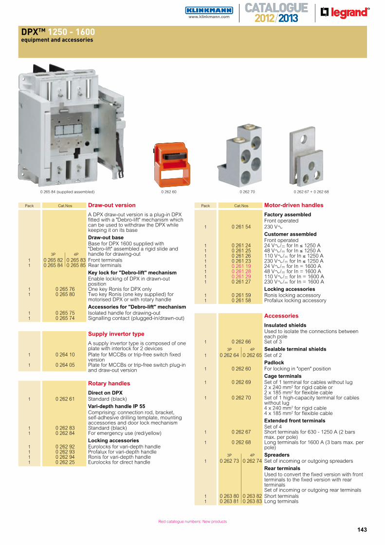
0 265 84 (supplied assembled) 0 262 60 0 262 70 0 262 67 + 0 262 68
Pack Cat.Nos Draw-out version
A DPX draw-out version is a plug-in DPX fitted with a "Debro-lift" mechanism which can be used to withdraw the DPX while keeping it on its base
Draw-out base Base for DPX 1600 supplied with "Debro-lift" assembled a rigid slide and 3P 4P handle for drawing-out 1 0 265 82 0 265 83 Front terminals 1 0 265 84 0 265 85 Rear terminals
Key lock for "Debro-lift" mechanism Enable locking of DPX in drawn-out
position 1 0 265 76 One key Ronis for DPX only 1 0 265 80 Two key Ronis (one key supplied) for
motorised DPX or with rotary handle
Accessories for "Debro-lift" mechanism 1 0 265 75 Isolated handle for drawing-out 1 0 265 74 Signalling contact (plugged-in/drawn-out)
Supply invertor type
A supply invertor type is composed of one plate with interlock for 2 devices
1 0 264 10 Plate for MCCBs or trip-free switch fixed version
1 0 264 05 Plate for MCCBs or trip-free switch plug-in and draw-out version
Rotary handles
Direct on DPX 1 0 262 61 Standard (black)
Vari-depth handle IP 55 Comprising: connection rod, bracket,
self-adhesive drilling template, mounting accessories and door lock mechanism
1 0 262 83 Standard (black) 1 0 262 84 For emergency use (red/yellow)
Locking accessories 1 0 262 92 Eurolocks for vari-depth handle 1 0 262 93 Profalux for vari-depth handle 1 0 262 94 Ronis for vari-depth handle 1 0 262 25 Eurolocks for direct handle
Pack Cat.Nos Motor-driven handles
Factory assembled Front operated 1 0 261 54 230 V± Customer assembled Front operated 1 0 261 24 24 V±/= for In ≤ 1250 A 1 0 261 25 48 V±/= for In ≤ 1250 A 1 0 261 26 110 V±/= for In ≤ 1250 A 1 0 261 23 230 V±/= for In ≤ 1250 A 1 0 261 19 24 V±/= for In = 1600 A 1 0 261 28 48 V±/= for In = 1600 A 1 0 261 29 110 V±/= for In = 1600 A 1 0 261 27 230 V±/= for In = 1600 A
Locking accessories 1 0 261 59 Ronis locking accessory 1 0 261 58 Profalux locking accessory
Accessories
Insulated shields Used to isolate the connections between
each pole 1 0 262 66 Set of 3
3P 4P Sealable terminal shields 1 0 262 64 0 262 65 Set of 2
Padlock 1 0 262 60 For locking in "open" position
Cage terminals 1 0 262 69 Set of 1 terminal for cables without lug
2 x 240 mm2 for rigid cable or 2 x 185 mm2 for flexible cable
1 0 262 70 Set of 1 high-capacity terminal for cables without lug 4 x 240 mm2 for rigid cable 4 x 185 mm2 for flexible cable
Extended front terminals Set of 4 1 0 262 67 Short terminals for 630 - 1250 A (2 bars
max. per pole) 1 0 262 68 Long terminals for 1600 A (3 bars max. per
pole)
3P 4P Spreaders 1 0 262 73 0 262 74 Set of incoming or outgoing spreaders
Rear terminals Used to convert the fixed version with front
terminals to the fixed version with rear terminals
Set of incoming or outgoing rear terminals 1 0 263 80 0 263 82 Short terminals 1 0 263 81 0 263 83 Long terminals
144
au iliaries au iliaries
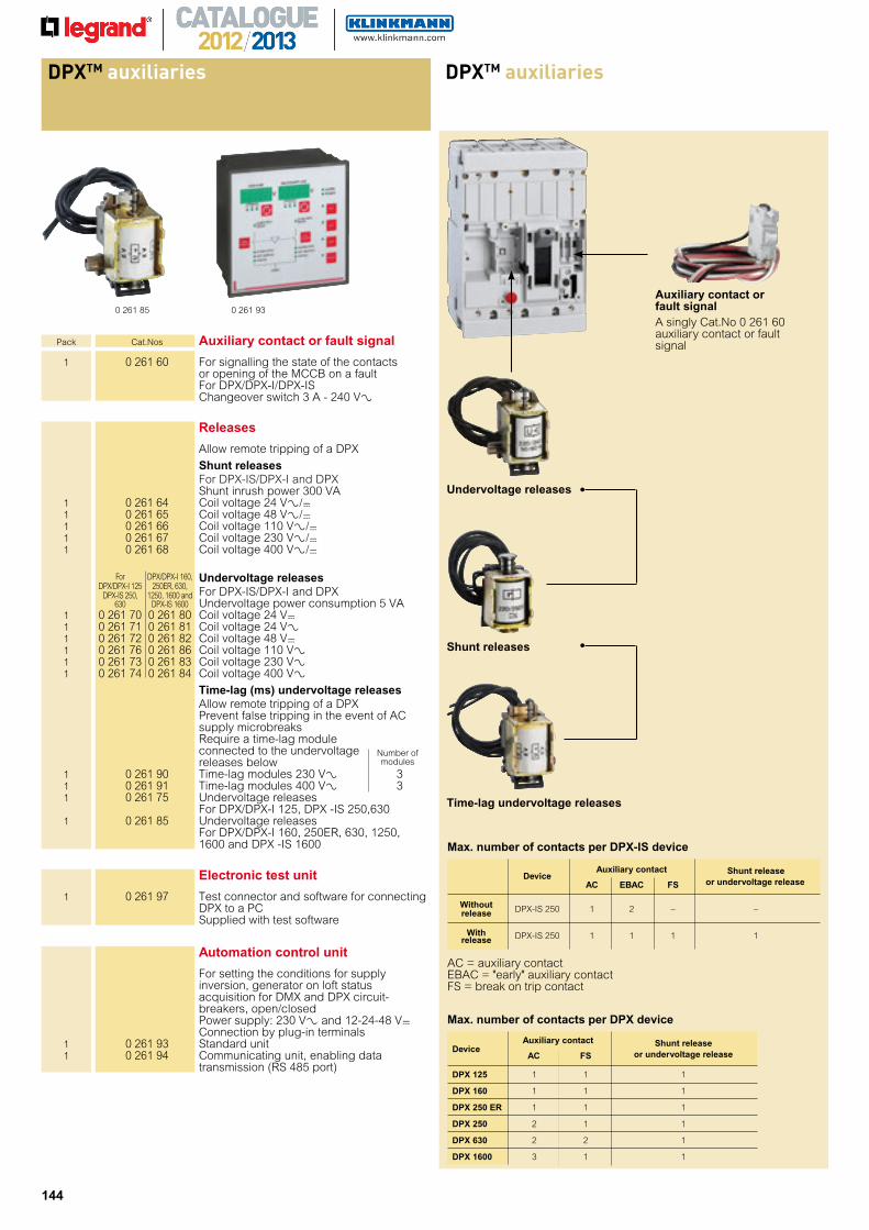
0 261 85
Pack Cat.Nos Auxiliary contact or fault signal
1 0 261 60 For signalling the state of the contacts or opening of the MCCB on a fault
For DPX/DPX-I/DPX-IS Changeover switch 3 A - 240 V±
Releases
Allow remote tripping of a DPX
Shunt releases For DPX-IS/DPX-I and DPX Shunt inrush power 300 VA 1 0 261 64 Coil voltage 24 V±/= 1 0 261 65 Coil voltage 48 V±/= 1 0 261 66 Coil voltage 110 V±/= 1 0 261 67 Coil voltage 230 V±/= 1 0 261 68 Coil voltage 400 V±/=
For DPX/DPX-I 160,
DPX/DPX-I 125 250ER, 630,
Undervoltage releases DPX-IS 250, 1250, 1600 and For DPX-IS/DPX-I and DPX 630 DPX-IS 1600 Undervoltage power consumption 5 VA 1 0 261 70 0 261 80 Coil voltage 24 V= 1 0 261 71 0 261 81 Coil voltage 24 V± 1 0 261 72 0 261 82 Coil voltage 48 V= 1 0 261 76 0 261 86 Coil voltage 110 V± 1 0 261 73 0 261 83 Coil voltage 230 V± 1 0 261 74 0 261 84 Coil voltage 400 V± Time-lag (ms) undervoltage releases Allow remote tripping of a DPX
Prevent false tripping in the event of AC supply microbreaks Require a time-lag module connected to the undervoltage releases below
1 0 261 90 Time-lag modules 230 V± 3 1 0 261 91 Time-lag modules 400 V± 3 1 0 261 75 Undervoltage releases
For DPX/DPX-I 125, DPX -IS 250,630 1 0 261 85 Undervoltage releases
For DPX/DPX-I 160, 250ER, 630, 1250, 1600 and DPX -IS 1600
Number ofmodules
0 261 93
Automation control unit
For setting the conditions for supply inversion, generator on loft status acquisition for DMX and DPX circuit-breakers, open/closed Power supply: 230 V± and 12-24-48 V= Connection by plug-in terminals
1 0 261 93 Standard unit 1 0 261 94 Communicating unit, enabling data
transmission (RS 485 port)
Auxiliary contact or fault signalA singly Cat.No 0 261 60 auxiliary contact or fault signal
Undervoltage releases
Shunt releases
Time-lag undervoltage releases
AC = auxiliary contactEBAC = "early" auxiliary contactFS = break on trip contact
Max. number of contacts per DPX-IS device
Auxiliary contact Shunt release Device
AC EBAC FS or undervoltage release
Without DPX-IS 250 1 2 – – release
With DPX-IS 250 1 1 1 1 release
Max. number of contacts per DPX device
Device
Auxiliary contact Shunt release
AC FS
or undervoltage release
DPX 125 1 1 1
DPX 160 1 1 1
DPX 250 ER 1 1 1
DPX 250 2 1 1
DPX 630 2 2 1
DPX 1600 3 1 1
Electronic test unit
1 0 261 97 Test connector and software for connecting DPX to a PC Supplied with test software


![MCCBs: DPX TM - Electroshops.roelectroshops.ro/blog/wp-content/uploads/2014/02/Disjunctoare-DPX-L... · TM] MCCBs: DPX TM The compact range of ... Type of MCCB E Ultimate breaking](https://img.pdfslide.net/doc/110x75/5adc8ef37f8b9ae1408bb720/mccbs-dpx-tm-mccbs-dpx-tm-the-compact-range-of-type-of-mccb-e-ultimate-breaking.jpg)