Embed Size (px)
Citation preview
OG4401AX Rev A, ECN 134442
D y n a m2 1 5 9 2 M a r i lw w w . d y t r a n .
OPERATING
4401AX VI
i c T r a nl a S t . • C h a t s. c o m • e - m a i l
G GUIDE – O
IBRATION R
s d u c e rs w o r t h , C A 9 1: i n f o @ d y t r a
OG4401AX
ECORDER
s a n d S3 1 1 • P h o n e n . c o m
S y s t e m s 8 1 8 - 7 0 0 - 7 8 1
s 8
Rev A, ECN 12775
Page | 2
Contents
I. Device Features ................................................................................................................................................. 3
II. Software Features ............................................................................................................................................. 3
III. Acronyms used in this manual .......................................................................................................................... 3
IV. Minimum System Requirements ....................................................................................................................... 4
V. Installation ......................................................................................................................................................... 4
VI. Operation .......................................................................................................................................................... 6
VII. Mechanical configuration and mounting ........................................................................................................ 11
VIII. Data recording considerations ........................................................................................................................ 12
IX. Software License, Restrictions, and Disclaimer ............................................................................................... 13
Note: As part of our commitment to continuous product improvement, Dytran shall make
modifications to this document without notice or restriction.
Rev A, ECN 12775
Page | 3
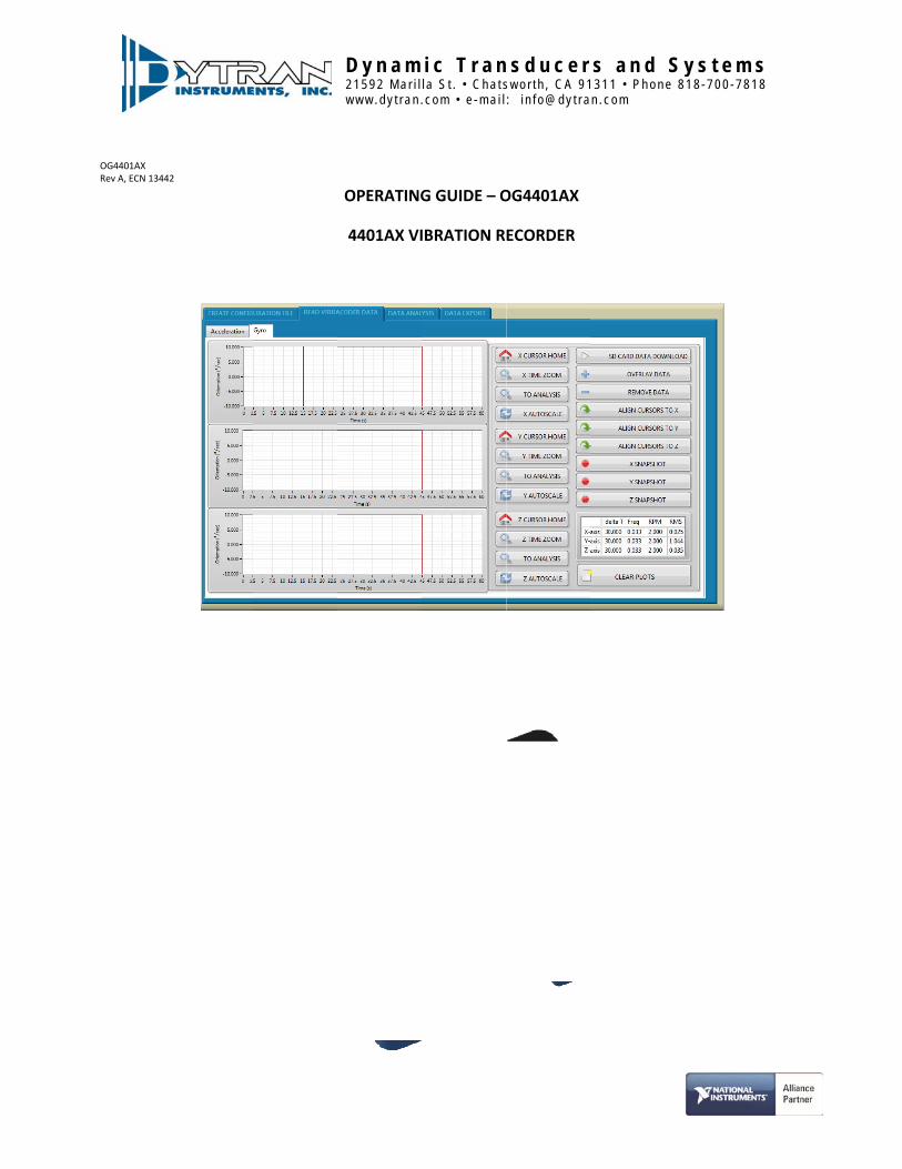
Dytran Instruments Model 4401AX is a vibration recorder with built‐in 3‐axis MEMS
accelerometer and 3‐axis Gyroscope capable of measuring and recording acceleration and
orientation in three orthogonal directions and pitch, yaw, and roll. This data is written to a
standard micro SD card.
I. DeviceFeatures‐System components:
4401AX Vibration Recorder
Approved SD card ‐ Sandisk Extreme Plus 32GB ‐ SDSQXVF‐032G‐GN6MA
9009 Software Toolkit (Can be downloaded from Dytran Vibration Recorder Product Page )
‐4401AX is powered through a rechargeable li‐po battery or external power from 8–32 V DC.
‐Built‐in firmware handles acceleration in three axes acceleration and gyroscope data storage
on the SD card.
II. SoftwareToolkitFeatures‐ Immediate data retrieval from the SD card to the PC ‐ Easy cursor operation for data selection, zoom, and cursor alignment ‐ Snap Shot with the press of a button ‐ Data overlay ‐ Anti‐Alias Filtering ‐ Oversampling ‐ FFT analysis ‐ Data export ‐ Real Time Stamp
III. AcronymsusedinthismanualGUI‐ Graphical User Interface FFT‐ Fast Fourier Transform JPG‐Joint Photographic File format ASCII‐American Standard Code for Information Interchange TDMS‐Technical Data Management Solution (Binary and ASCII file saving option for smaller file sizes with stored header information)
Rev A, ECN 12775
Page | 4
IV. MinimumSystemRequirementsDesktop or a Laptop x86 based personal computer Operating System: Windows Vista/Seven/Win8 32/64‐bit CPU: Intel i3 or better RAM: 1 GB Hard Disk space: 1 GB Display Resolution 1280×780.
V. Installation
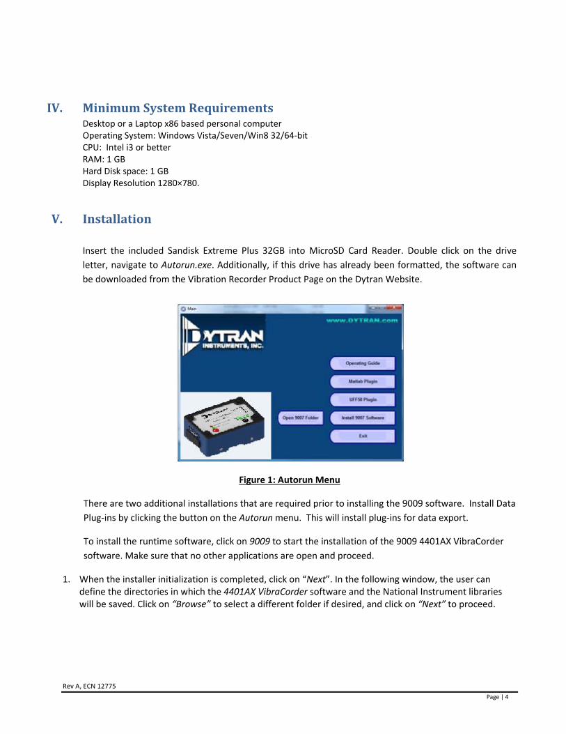
Insert the included Sandisk Extreme Plus 32GB into MicroSD Card Reader. Double click on the drive
letter, navigate to Autorun.exe. Additionally, if this drive has already been formatted, the software can
be downloaded from the Vibration Recorder Product Page on the Dytran Website.
Figure 1: Autorun Menu
There are two additional installations that are required prior to installing the 9009 software. Install Data
Plug‐ins by clicking the button on the Autorun menu. This will install plug‐ins for data export.
To install the runtime software, click on 9009 to start the installation of the 9009 4401AX VibraCorder
software. Make sure that no other applications are open and proceed.
1. When the installer initialization is completed, click on “Next”. In the following window, the user can define the directories in which the 4401AX VibraCorder software and the National Instrument libraries will be saved. Click on “Browse” to select a different folder if desired, and click on “Next” to proceed.

Rev A, ECN 12775
Page | 5
Figure 2: Install Destination Directory
2. In the next window, select “I accept the license agreement...” to accept Dytran 4401AX VibraCorder license conditions and then click on “Next”.
3. Select “I accept the license agreement...” to accept National Instrument license conditions and then click on “Next”.
4. At this point, select “I accept 2 license agreement(s)...” to accept Microsoft Silverlight 5 EULA and Microsoft Silverlight Privacy Statement conditions. Click on “Next” to proceed.
5. The “Start Installation” window will appear. It indicates whether a component will be upgraded or installed for the first time. Click on “Next” to start the installation. This process may take a few minutes. Please wait until the installation is complete.
6. When the installation is complete, click on “Next” to proceed. 7. If asked, reboot your PC by clicking on “Restart” in the following window.
Figure 3: Restart after Installation Completed.

Rev A, ECN 12775
Page | 6
VI. Operation
WARNING: Do not connector or disconnect the 25 pin external micro d‐sub connector while the
4401 is powered. This may result in damage to the unit and/or loss of data.
1. After the computer is restarted, the user will find the “9009 VibraCorder” icon in the Windows menu, as
shown in Figure below. A Shortcut will also be created on the Desktop for ease of access.
Figure 4: VibraCorder Icon.
2. Insert the SD card into your PC and launch the software.
Figure 5: 9009 Software
3. Create configuration file – this tab allows the creation of the configuration file for the data acquisition.
Rev A, ECN 12775
Page | 7
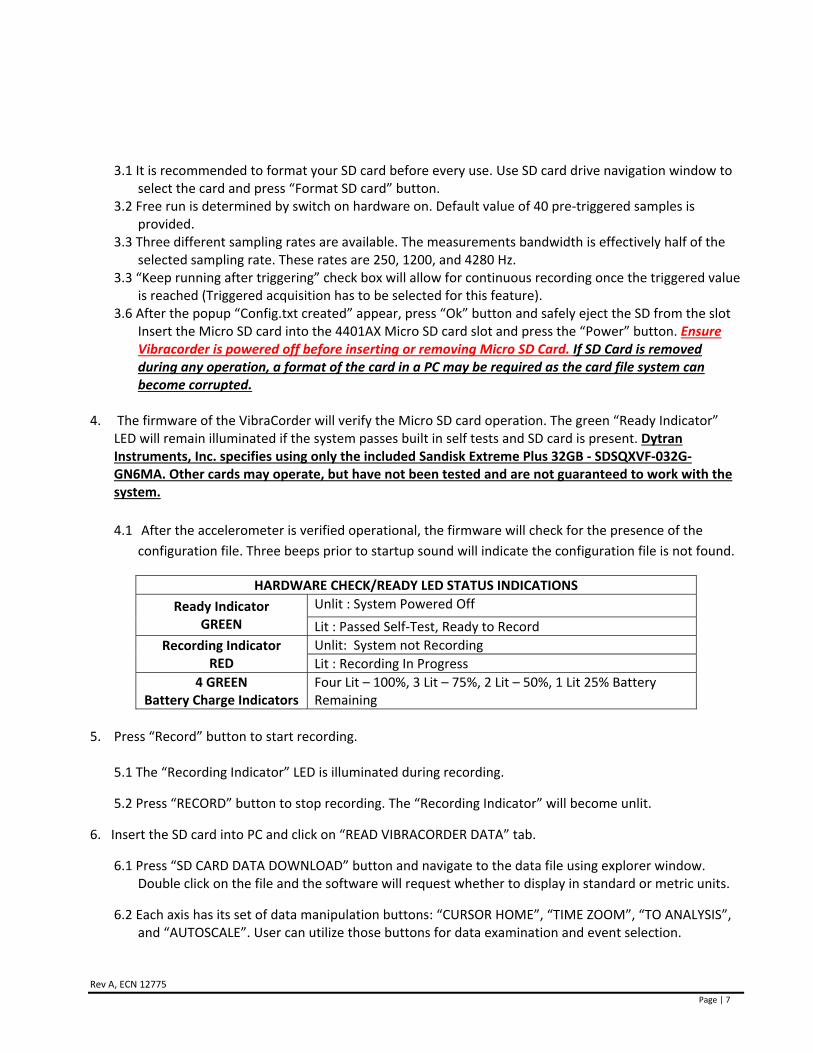
3.1 It is recommended to format your SD card before every use. Use SD card drive navigation window to
select the card and press “Format SD card” button. 3.2 Free run is determined by switch on hardware on. Default value of 40 pre‐triggered samples is
provided. 3.3 Three different sampling rates are available. The measurements bandwidth is effectively half of the
selected sampling rate. These rates are 250, 1200, and 4280 Hz. 3.3 “Keep running after triggering” check box will allow for continuous recording once the triggered value
is reached (Triggered acquisition has to be selected for this feature). 3.6 After the popup “Config.txt created” appear, press “Ok” button and safely eject the SD from the slot
Insert the Micro SD card into the 4401AX Micro SD card slot and press the “Power” button. Ensure Vibracorder is powered off before inserting or removing Micro SD Card. If SD Card is removed during any operation, a format of the card in a PC may be required as the card file system can become corrupted.
4. The firmware of the VibraCorder will verify the Micro SD card operation. The green “Ready Indicator” LED will remain illuminated if the system passes built in self tests and SD card is present. Dytran Instruments, Inc. specifies using only the included Sandisk Extreme Plus 32GB ‐ SDSQXVF‐032G‐GN6MA. Other cards may operate, but have not been tested and are not guaranteed to work with the system.
4.1 After the accelerometer is verified operational, the firmware will check for the presence of the
configuration file. Three beeps prior to startup sound will indicate the configuration file is not found.
HARDWARE CHECK/READY LED STATUS INDICATIONS
Ready Indicator GREEN
Unlit : System Powered Off
Lit : Passed Self‐Test, Ready to Record
Recording Indicator RED
Unlit: System not Recording
Lit : Recording In Progress
4 GREEN Battery Charge Indicators
Four Lit – 100%, 3 Lit – 75%, 2 Lit – 50%, 1 Lit 25% Battery Remaining
5. Press “Record” button to start recording.
5.1 The “Recording Indicator” LED is illuminated during recording.
5.2 Press “RECORD” button to stop recording. The “Recording Indicator” will become unlit.
6. Insert the SD card into PC and click on “READ VIBRACORDER DATA” tab.
6.1 Press “SD CARD DATA DOWNLOAD” button and navigate to the data file using explorer window. Double click on the file and the software will request whether to display in standard or metric units.
6.2 Each axis has its set of data manipulation buttons: “CURSOR HOME”, “TIME ZOOM”, “TO ANALYSIS”, and “AUTOSCALE”. User can utilize those buttons for data examination and event selection.
Rev A, ECN 127
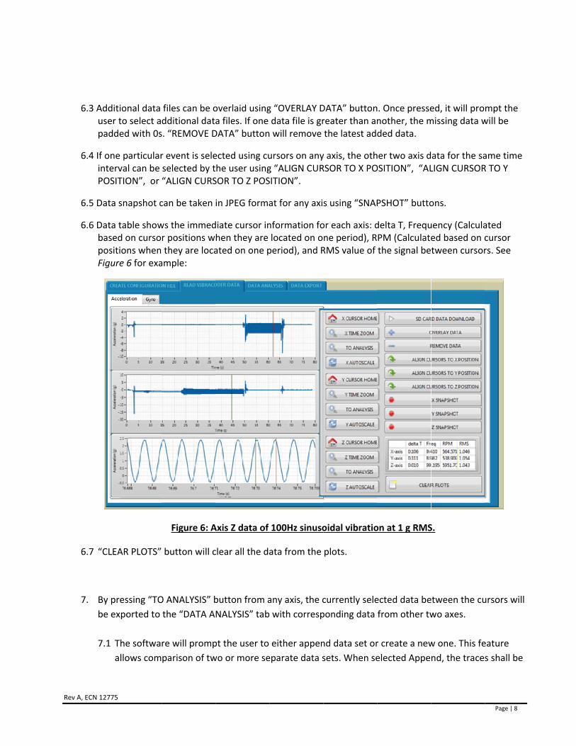
6.3 Adusepa
6.4 If ointPO
6.5 Dat
6.6 DatbapoFig
6.7 “C
7. By
be
7.1
775
ditional data er to select added with 0s
one particularterval can be OSITION”, or
ta snapshot c
ta table showsed on cursoositions whengure 6 for exa
LEAR PLOTS”
y pressing “TO
e exported to
1 The softwa
allows com
files can be odditional dats. “REMOVE D
r event is seleselected by t“ALIGN CURS
can be taken
ws the immedr positions w they are locaample:
Figure 6: A
button will c
O ANALYSIS” b
the “DATA A
re will promp
parison of tw
overlaid usinga files. If one DATA” button
ected using cuhe user usingSOR TO Z POS
in JPEG forma
diate cursor inhen they are ated on one p
Axis Z data of
clear all the da
button from a
NALYSIS” tab
pt the user to
wo or more se
g “OVERLAY Ddata file is gr will remove
ursors on anyg “ALIGN CURSITION”.
at for any axi
nformation folocated on operiod), and R
100Hz sinuso
ata from the
any axis, the c
with corresp
either appen
eparate data s
DATA” buttonreater than anthe latest ad
y axis, the othRSOR TO X PO
s using “SNAP
or each axis: dne period), RRMS value of
oidal vibratio
plots.
currently sele
ponding data
nd data set or
sets. When se
n. Once pressenother, the mded data.
her two axis dOSITION”, “AL
PSHOT” butto
delta T, FrequPM (Calculatethe signal be
on at 1 g RMS
ected data be
from other tw
r create a new
elected Appe
ed, it will promissing data w
ata for the saLIGN CURSOR
ons.
uency (Calculaed based on ctween cursor
S.
etween the cu
wo axes.
w one. This fe
nd, the trace
Page | 8
mpt the will be
ame time R TO Y
ated cursor rs. See
ursors will
eature
s shall be
Rev A, ECN 12775
Page | 9
overlaid. When selected new, all the previously displayed data shall be erased and substituted
with newly imported data set.
7.2 “RELOAD SELECTED DATA” button shall reload the original set of data into the analysis window.
7.3 “LOW PASS FILTER” and “HIGH PASS FILTER” buttons shall apply specified filter to the data, user
shall be prompted for corner frequency and filter order. Butterworth topology is used.
7.4 “SINGLE INTEGRATION” and “DOUBLE INTEGRATION” buttons will apply either single or double
numerical integration. The software shall automatically apply a high pass filter before performing
integration (to avoid any data run off). User shall be prompted for corner frequency of the filter.
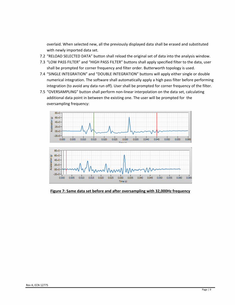
7.5 “OVERSAMPLING” button shall perform non‐linear interpolation on the data set, calculating
additional data point in between the existing one. The user will be prompted for the
oversampling frequency:
Figure 7: Same data set before and after oversampling with 32,000Hz frequency
Rev A, ECN 12775
Page | 10
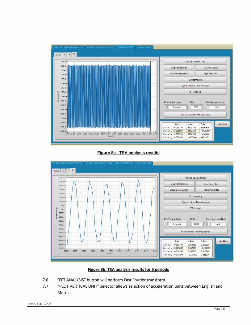
Figure 8a - TSA analysis results
Figure 8b: TSA analysis results for 5 periods
7.6 “FFT ANALYSIS” button will perform Fast Fourier transform.
7.7 “PLOT VERTICAL UNIT” selector allows selection of acceleration units between English and
Metric.

Rev A, ECN 12775
Page | 11
7.8 “RPM” control requires user input for TSA calculations and cursor location.
7.9 “PLOT HORIZONTAL UNITS” allows the change between Hertz, Orders, and RPM for FFT
graph.
7.10 “GET RMS” button shall show the RMS signal value for each axis.
8. “DATA EXPORT” tab allows the export of the data to conventional file formats: .csv, .mat, .tdms, .uff,
and .sqlite
8.1 User shall define the location of the file on the PC using the explorer.
8.2 If “EXPORT ALL RAW DATA” is checked, the software will export all the raw data from the
measurements file. If the “EXPORT ALL RAW DATA” is not checked, the software will export
only the content of the analysis screen.
Note: If running from external power through the 25 pin micro D‐sub external connector, the Vibracorder
should be powered on and off via an external power supply. Please ensure that external power is off when
performing any connection or disconnection to D‐sub connector. Turning the Vibracorder on with tactile
buttons (battery powered operation) will not allow remote power cycling of the Vibracorder.
VII. Mechanicalconfigurationandmounting
1. Refer to 127‐4401A2 outline drawing for physical dimensions of the device.
2. Model 4401AX must be mounted using the supplied removable mounting plate and screws.
Select a desired hole pattern as outlined on 127‐4401A2 drawing (2.00” x 2.00”, 2.00”x 1.00” or 1.00”x1.00”),
drill and tap four 10‐32 holes x 0.35” minimum depth. Mount the plate to the test surface using the supplied
four 10‐32 low profile head screws as shown in Figure 9. Torque screws to 28 lb‐in.
Figure 9
Rev A, ECN 12775
Page | 12
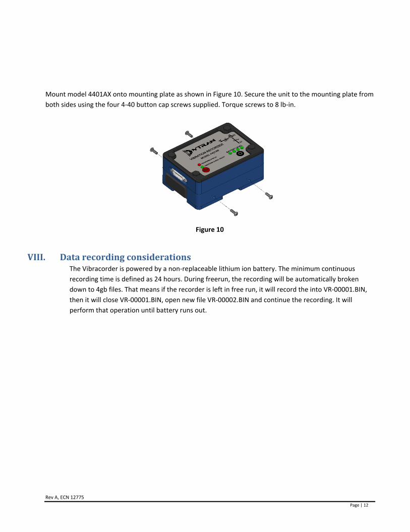
Mount model 4401AX onto mounting plate as shown in Figure 10. Secure the unit to the mounting plate from
both sides using the four 4‐40 button cap screws supplied. Torque screws to 8 lb‐in.
Figure 10
VIII. DatarecordingconsiderationsThe Vibracorder is powered by a non‐replaceable lithium ion battery. The minimum continuous
recording time is defined as 24 hours. During freerun, the recording will be automatically broken
down to 4gb files. That means if the recorder is left in free run, it will record the into VR‐00001.BIN,
then it will close VR‐00001.BIN, open new file VR‐00002.BIN and continue the recording. It will
perform that operation until battery runs out.
Rev A, ECN 12775
Page | 13
IX. SoftwareLicense,Restrictions,andDisclaimer
LICENSE: The Dytran Instruments, Inc. (Dytran) 4401AX VibraCorder™ software application (the Software) available for download via the Dytran website, via email, or made available on portable storage devices shipped with Dytran products is a free license for Dytran customers to use with Dytran products. Dytran encourages you to know the possible risks involved in the download and use of software from the internet. You are solely responsible for protecting yourself, your data, your systems and your hardware used in connection with the Software. Dytran will not be liable for any damages suffered from the use of the Software.
RESTRICTIONS: Neither the Software Licensee nor any Licensed User may rent or lease the Software. Neither the Software Licensee nor any Licensed User may modify, reverse engineer, decompile or disassemble the Software.
DISCLAIMER: BY USING THE SOFTWARE, YOU EXPRESSLY AGREE THAT ALL RISKS ASSOCIATED WITH THE PERFORMANCE AND QUALITY OF THE SOFTWARE IS ASSUMED SOLELY BY YOU. DYTRAN SHALL NOT BE LIABLE FOR ANY DIRECT, INDIRECT, INCIDENTAL, SPECIAL OR CONSEQUENTIAL DAMAGES ARISING OUT OF THE USE OF OR INABILITY TO USE THE SOFTWARE, EVEN IF DYTRAN HAS BEEN ADVISED OF THE POSSIBILITY OF SUCH DAMAGES.
THE SOFTWARE IS MADE AVAILABLE BY DYTRAN "AS IS" AND "WITH ALL FAULTS". DYTRAN DOES NOT MAKE ANY REPRESENTATIONS OR WARRANTIES OF ANY KIND, EITHER EXPRESS OR IMPLIED, CONCERNING THE QUALITY, SAFETY OR SUITABILITY OF THE SOFTWARE; INCLUDING WITHOUT LIMITATION ANY IMPLIED WARRANTIES OF MERCHANTABILITY, FITNESS FOR A PARTICULAR PURPOSE, OR NON-INFRINGEMENT. IN NO EVENT WILL DYTRAN BE LIABLE FOR ANY INDIRECT, PUNITIVE, SPECIAL, INCIDENTAL OR CONSEQUENTIAL DAMAGES THROUGH THE USE OF THE SOFTWARE HOWEVER THEY MAY ARISE AND EVEN IF DYTRAN HAS BEEN PREVIOUSLY ADVISED OF THE POSSIBILITY OF SUCH DAMAGES.