Embed Size (px)
Citation preview
2006/09 – Subject to change – Products 2006 4 / 7.1-13
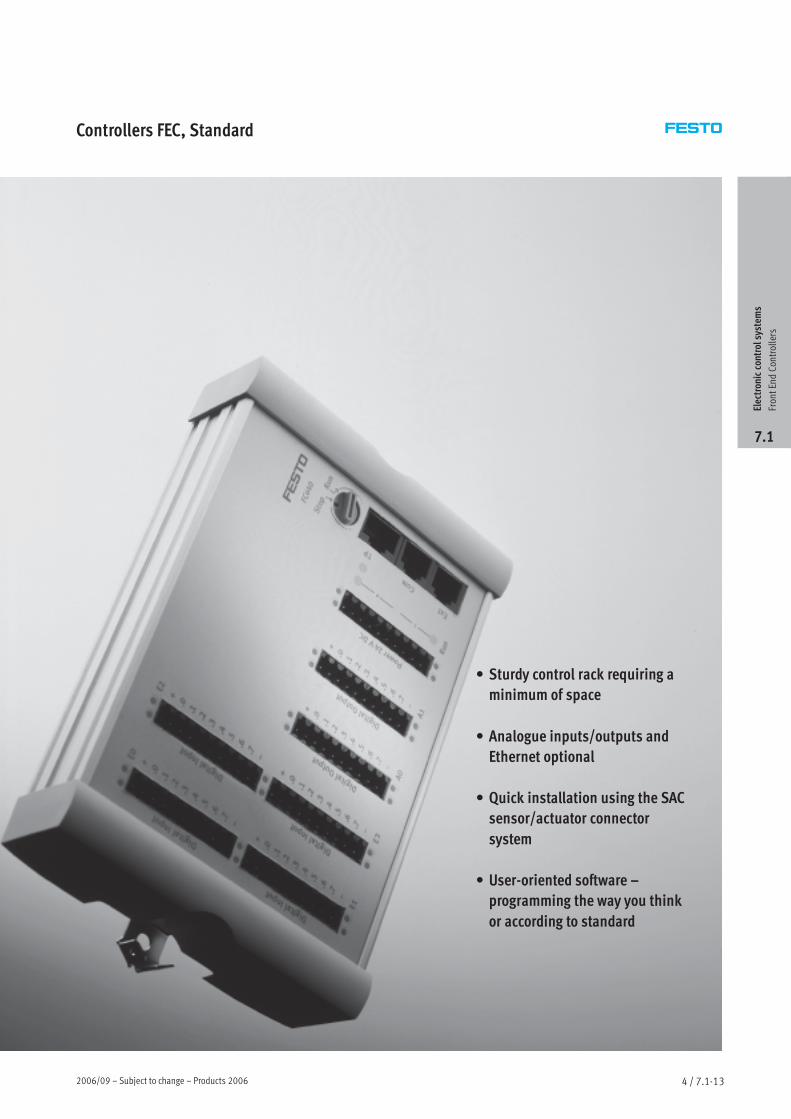
Controllers FEC, Standard
• Sturdy control rack requiring a
minimum of space
• Analogue inputs/outputs and
Ethernet optional
• Quick installation using the SAC
sensor/actuator connector
system
• User-oriented software –
programming the way you think
or according to standard
Electroniccontrolsystem
s
FrontEndControllers
7.1
Products 2006 – Subject to change – 2006/094 / 7.1-14
Controllers FEC, StandardKey features
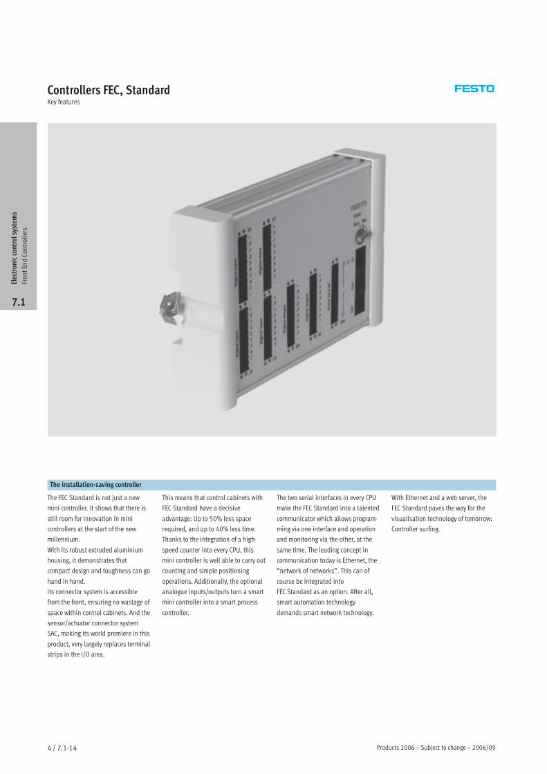
The installation-saving controller
The FEC Standard is not just a new
mini controller. It shows that there is
still room for innovation in mini
controllers at the start of the new
millennium.
With its robust extruded aluminium
housing, it demonstrates that
compact design and toughness can go
hand in hand.
Its connector system is accessible
from the front, ensuring no wastage of
space within control cabinets. And the
sensor/actuator connector system
SAC, making its world premiere in this
product, very largely replaces terminal
strips in the I/O area.
This means that control cabinets with
FEC Standard have a decisive
advantage: Up to 50% less space
required, and up to 40% less time.
Thanks to the integration of a high-
speed counter into every CPU, this
mini controller is well able to carry out
counting and simple positioning
operations. Additionally, the optional
analogue inputs/outputs turn a smart
mini controller into a smart process
controller.
The two serial interfaces in every CPU
make the FEC Standard into a talented
communicator which allows program-
ming via one interface and operation
and monitoring via the other, at the
same time. The leading concept in
communication today is Ethernet, the
“network of networks”. This can of
course be integrated into
FEC Standard as an option. After all,
smart automation technology
demands smart network technology.
With Ethernet and a web server, the
FEC Standard paves the way for the
visualisation technology of tomorrow:
Controller surfing.
Electroniccontrolsystem
s
FrontEndControllers
7.1
2006/09 – Subject to change – Products 2006 4 / 7.1-15
Controllers FEC, StandardKey features
Hardware
The FEC Standard has a clip for a top-
hat rail and corner holes for bolt-
mounting using a mounting plate. All
connections are accessible from the
front; there is no need for additional
space for connections from above or
below.
Power supply
The FEC Standard is powered
exclusively via 24 V DC as per modern
control cabinet technology.
24 V DC (+25%/-15%) power supply
for the controller itself,
24 V DC (+/–25%) power supply for
the input signals, positive switching,
24 V DC output signals 400 mA, proof
against short-circuits and low-
resistance loads.
The analogue inputs/outputs are
0(4) ... 20 mA I/Os, 12 bit resolution.
Serial interfaces
Every FEC Standard is equipped with
two serial interfaces – COM and EXT.
These are universal TTL interfaces
with a maximum data transmission
rate of 115 kbits/s. Depending on
requirements, the interfaces can be
used as RS232c (SM14 or SM15) or
RS485 (SM35) interfaces. Adapters
should be ordered separately. The
COM interface is generally used
together with the SM14 for program-
ming, while the EXT interface can be
used for an MMI device, a modem or
other devices with a serial interface.
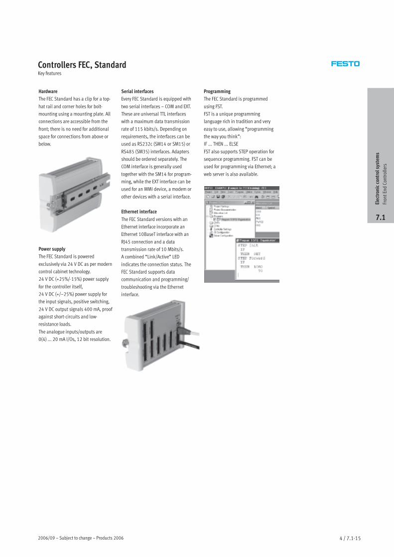
Ethernet interface
The FEC Standard versions with an
Ethernet interface incorporate an
Ethernet 10BaseT interface with an
RJ45 connection and a data
transmission rate of 10 Mbits/s.
A combined “Link/Active” LED
indicates the connection status. The
FEC Standard supports data
communication and programming/
troubleshooting via the Ethernet
interface.
Programming
The FEC Standard is programmed
using FST.
FST is a unique programming
language rich in tradition and very
easy to use, allowing “programming
the way you think”:
IF ... THEN ... ELSE
FST also supports STEP operation for
sequence programming. FST can be
used for programming via Ethernet; a
web server is also available.
Electroniccontrolsystem
s
FrontEndControllers
7.1
Products 2006 – Subject to change – 2006/094 / 7.1-16
Controllers FEC, StandardKey features
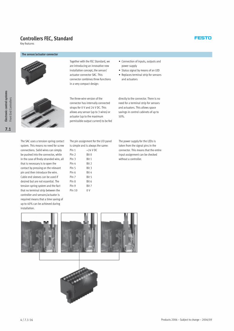
The sensor/actuator connector
Together with the FEC Standard, we
are introducing an innovative new
installation concept, the sensor/
actuator connector SAC. This
connector combines three functions
in a very compact design:
• Connection of inputs, outputs and
power supply
• Status signal by means of an LED
• Replaces terminal strip for sensors
and actuators
The three-wire version of the
connector has internally connected
straps for 0 V and 24 V DC. This
allows any sensor (up to 3 wires) or
actuator (up to the maximum
permissible output current) to be fed
directly to the connector. There is no
need for a terminal strip for sensors
and actuators. This allows space
savings in control cabinets of up to
50%.
The SAC uses a tension-spring contact
system. This means no need for screw
connections. Solid wires can simply
be pushed into the connector, while
in the case of finely-stranded wire, all
that is necessary is to open the
contact by pressing on the relevant
pin and then introduce the wire.
Cable end sleeves can be used if
desired but are not essential. The
tension-spring system and the fact
that no terminal strip between the
controller and sensors/actuator is
required means that a time saving of
up to 40% can be achieved during
installation.
The pin assignment for the I/O panel
is simple and is always the same:
Pin 1 +24 V DC
Pin 2 Bit 0
Pin 3 Bit 1
Pin 4 Bit 2
Pin 5 Bit 3
Pin 6 Bit 4
Pin 7 Bit 5
Pin 8 Bit 6
Pin 9 Bit 7
Pin 10 0 V
The power supply for the LEDs is
taken from the signal pins in the
connector. This means that the entire
input assignment can be checked
without a controller.
Electroniccontrolsystem
s
FrontEndControllers
7.1
2006/09 – Subject to change – Products 2006 4 / 7.1-17
Controllers FEC, StandardKey features
Programming with FST
Programming the way you think
How do we describe a machine?
“When a workpiece reaches here, this
cylinder should advance.”
How does the software interpret this?
Or does your machine work through a
sequence step by step?
“First, this cylinder must advance and
stop the workpiece, and then the
workpiece must be clamped, and then
finally...”
How, for example, can we sub-divide
a task?
Program 0: Organisation
Program 1: Set-up program
Program 2: Automation
program
Program 3: Fault monitoring
Program 4: Manual operation
.
.
.
Program 63: Troubleshooting
program
How does one controller
communicate with another?
Every controller with Ethernet can
send and receive data from every
other controller within a network – no
matter whether this data relates to
inputs, outputs, flags or registers.
Central programming of distributed
controllers
Every controller within a network can
be programmed from any desired
network interface.
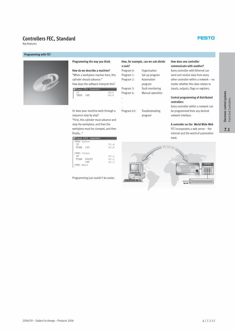
A controller on the World Wide Web
FST incorporates a web server – the
Internet and the world of automation
meet.
Programming just couldn’t be easier.
Electroniccontrolsystem
s
FrontEndControllers
7.1
Products 2006 – Subject to change – 2006/094 / 7.1-18
Controllers FEC, StandardProduct range overview
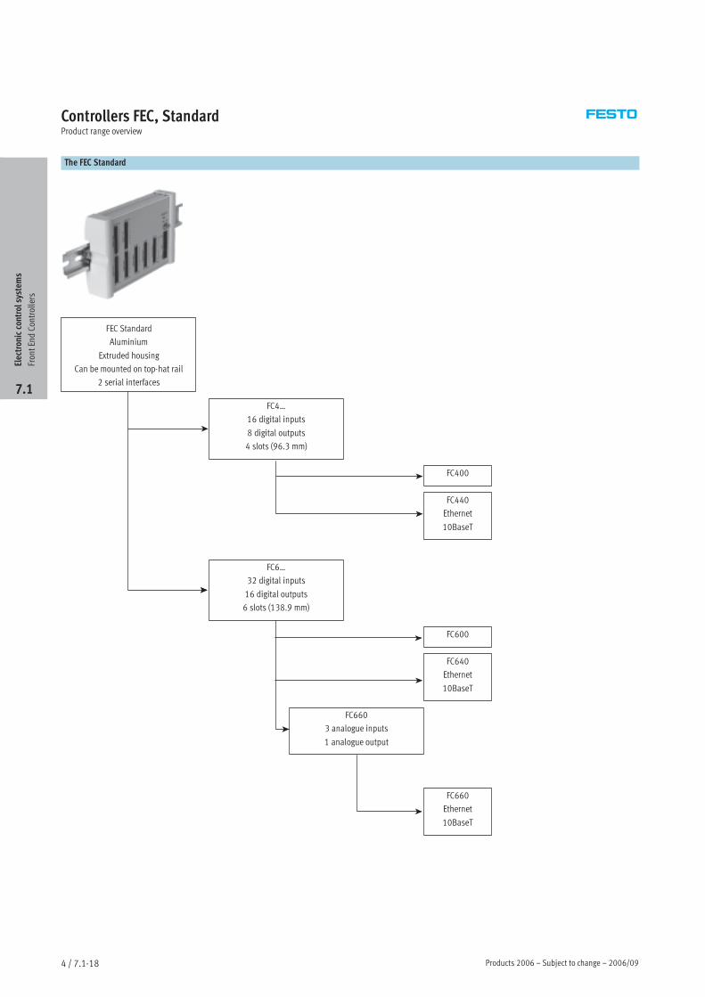
The FEC Standard
FEC Standard
Aluminium
Extruded housing
Can be mounted on top-hat rail
2 serial interfaces
FC4…
16 digital inputs
8 digital outputs
4 slots (96.3 mm)
FC400
FC440
Ethernet
10BaseT
FC6…
32 digital inputs
16 digital outputs
6 slots (138.9 mm)
FC600
FC640
Ethernet
10BaseT
FC660
3 analogue inputs
1 analogue output
FC660
Ethernet
10BaseT
Electroniccontrolsystem
s
FrontEndControllers
7.1
2006/09 – Subject to change – Products 2006 4 / 7.1-19
Controllers FEC, StandardProduct range overview
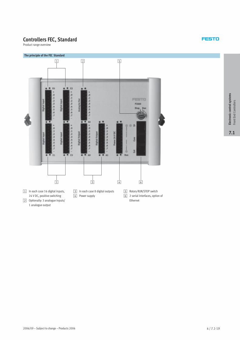
The principle of the FEC Standard
1
1
2
3
5
4 6
1 In each case 16 digital inputs,
24 V DC, positive-switching
2 Optionally: 3 analogue inputs/
1 analogue output
3 In each case 8 digital outputs
4 Power supply
5 Rotary RUN/STOP switch
6 2 serial interfaces, option of
Ethernet
Electroniccontrolsystem
s
FrontEndControllers
7.1
Products 2006 – Subject to change – 2006/094 / 7.1-20
Controllers FEC, StandardTechnical data
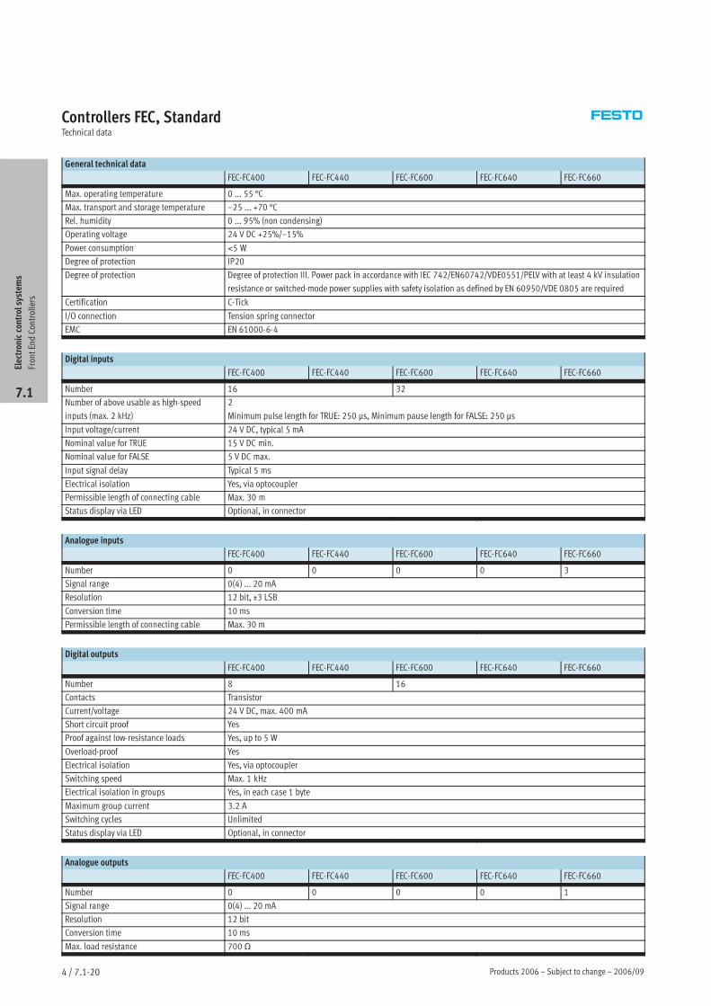
General technical data
FEC-FC400 FEC-FC440 FEC-FC600 FEC-FC640 FEC-FC660
Max. operating temperature 0 ... 55 °C
Max. transport and storage temperature –25 ... +70 °C
Rel. humidity 0 ... 95% (non condensing)
Operating voltage 24 V DC +25%/–15%
Power consumption <5 W
Degree of protection IP20
Degree of protection Degree of protection III. Power pack in accordance with IEC 742/EN60742/VDE0551/PELV with at least 4 kV insulation
resistance or switched-mode power supplies with safety isolation as defined by EN 60950/VDE 0805 are required
Certification C-Tick
I/O connection Tension spring connector
EMC EN 61000-6-4
Digital inputs
FEC-FC400 FEC-FC440 FEC-FC600 FEC-FC640 FEC-FC660
Number 16 32
Number of above usable as high-speed
inputs (max. 2 kHz)
2
Minimum pulse length for TRUE: 250 µs, Minimum pause length for FALSE: 250 µs
Input voltage/current 24 V DC, typical 5 mA
Nominal value for TRUE 15 V DC min.
Nominal value for FALSE 5 V DC max.
Input signal delay Typical 5 ms
Electrical isolation Yes, via optocoupler
Permissible length of connecting cable Max. 30 m
Status display via LED Optional, in connector
Analogue inputs
FEC-FC400 FEC-FC440 FEC-FC600 FEC-FC640 FEC-FC660
Number 0 0 0 0 3
Signal range 0(4) ... 20 mA
Resolution 12 bit, ±3 LSB
Conversion time 10 ms
Permissible length of connecting cable Max. 30 m
Digital outputs
FEC-FC400 FEC-FC440 FEC-FC600 FEC-FC640 FEC-FC660
Number 8 16
Contacts Transistor
Current/voltage 24 V DC, max. 400 mA
Short circuit proof Yes
Proof against low-resistance loads Yes, up to 5 W
Overload-proof Yes
Electrical isolation Yes, via optocoupler
Switching speed Max. 1 kHz
Electrical isolation in groups Yes, in each case 1 byte
Maximum group current 3.2 A
Switching cycles Unlimited
Status display via LED Optional, in connector
Analogue outputs
FEC-FC400 FEC-FC440 FEC-FC600 FEC-FC640 FEC-FC660
Number 0 0 0 0 1
Signal range 0(4) ... 20 mA
Resolution 12 bit
Conversion time 10 ms
Max. load resistance 700 Ω
Electroniccontrolsystem
s
FrontEndControllers
7.1
2006/09 – Subject to change – Products 2006 4 / 7.1-21
Controllers FEC, StandardTechnical data
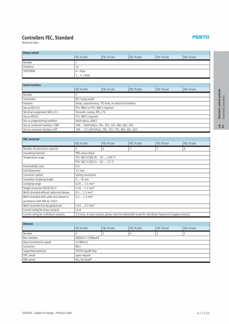
Rotary switch
FEC-FC400 FEC-FC440 FEC-FC600 FEC-FC640 FEC-FC660
Number 1
Positions 16
STOP/RUN 0 = Stop
1 ... F = RUN
Serial interface
FEC-FC400 FEC-FC440 FEC-FC600 FEC-FC640 FEC-FC660
Number 2
Connection RJ12 plug socket
Features Serial, asynchronous, TTL level, no electrical isolation
Use as RS232c PS1-SM14 or PS1-SM15 required
Terminal assignment SM14/15 Transmit, receive, RTS, CTS
Use as RS485 PS1-SM35 required
Use as programming interface 9600 bits/s, 8/N/1
Use as universal interface: COM 300 ... 9600 bits/s, 7N1, 7E1, 7O1, 8N1, 8E1, 8O1
Use as universal interface: EXT 300 ... 115,000 bits/s, 7N1, 7E1, 7O1, 8N1, 8E1, 8O1
SAC connector
FEC-FC400 FEC-FC440 FEC-FC600 FEC-FC640 FEC-FC660
Number of connectors required 4 4 7 7 8
Insulating material PBT, colour black
Temperature range PS1-SAC10/SAC30: –20 ... +100 °Cp g
PS1-SAC11/SAC31: –20 ... +75 °C
Flammability class V-0
Grid dimension 3.5 mm
Connector system Spring connection
Insulation-stripping length 9 ... 10 mm
Clamping range 0.05 ... 1.5 mm2
Single-conductor H05(07)V-U 0.20 ... 1.5 mm2
Multi-stranded without cable end sleeves 0.5 ... 1.5 mm2
Multi-stranded with cable end sleeves in
accordance with DIN 46 228/1
0.5 ... 1.5 mm2
Multi-stranded hot-dip galvanized 0.05 ... 0.2 mm2
Current rating for strap contacts 16 A
Current rating for individual contacts 2 A (max. 6 A per contact, please note the admissible loads for distributor board and supply contacts)
Ethernet
FEC-FC400 FEC-FC440 FEC-FC600 FEC-FC640 FEC-FC660
Number 0 1 0 1 1
Bus interface IEEE802.3 (10BaseT)
Data transmission speed 10 Mbits/s
Connector RJ45
Supported protocols TCP/IP, EasyIP, http
OPC server upon request
DDE server Yes, for EasyIP
Electroniccontrolsystem
s
FrontEndControllers
7.1
Products 2006 – Subject to change – 2006/094 / 7.1-22
Controllers FEC, StandardTechnical data
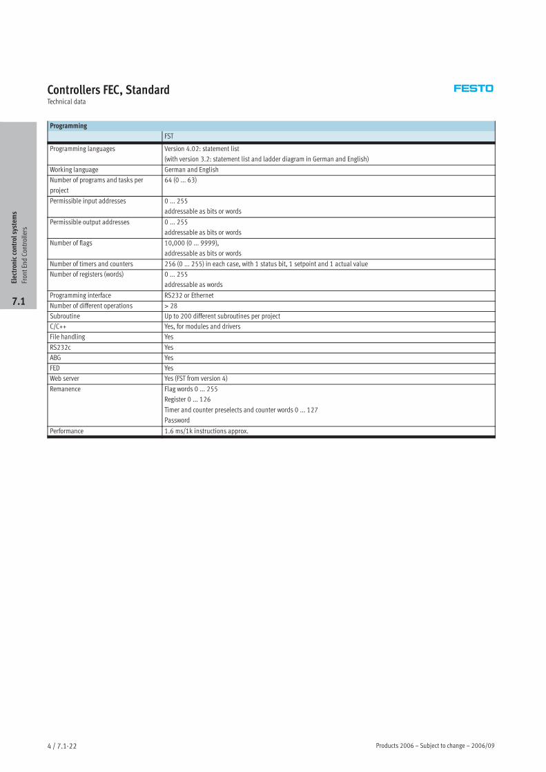
Programming
FST
Programming languages Version 4.02: statement list
(with version 3.2: statement list and ladder diagram in German and English)
Working language German and English
Number of programs and tasks per
project
64 (0 ... 63)
Permissible input addresses 0 ... 255
addressable as bits or words
Permissible output addresses 0 ... 255
addressable as bits or words
Number of flags 10,000 (0 ... 9999),
addressable as bits or words
Number of timers and counters 256 (0 ... 255) in each case, with 1 status bit, 1 setpoint and 1 actual value
Number of registers (words) 0 ... 255
addressable as words
Programming interface RS232 or Ethernet
Number of different operations > 28
Subroutine Up to 200 different subroutines per project
C/C++ Yes, for modules and drivers
File handling Yes
RS232c Yes
ABG Yes
FED Yes
Web server Yes (FST from version 4)
Remanence Flag words 0 ... 255
Register 0 ... 126
Timer and counter preselects and counter words 0 ... 127
Password
Performance 1.6 ms/1k instructions approx.
Electroniccontrolsystem
s
FrontEndControllers
7.1
2006/09 – Subject to change – Products 2006 4 / 7.1-23
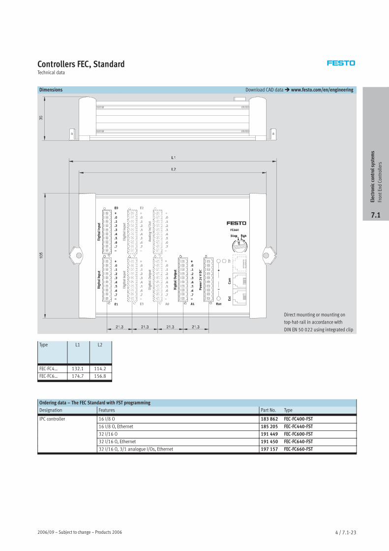
Controllers FEC, StandardTechnical data
Dimensions Download CAD data www.festo.com/en/engineering
Direct mounting or mounting on
top-hat-rail in accordance with
DIN EN 50 022 using integrated clip
Type L1 L2
FEC-FC4… 132.1 114.2
FEC-FC6… 174.7 156.8
Ordering data – The FEC Standard with FST programming
Designation Features Part No. Type
IPC controller 16 I/8 O 183 862 FEC-FC400-FST
16 I/8 O, Ethernet 185 205 FEC-FC440-FST
32 I/16 O 191 449 FEC-FC600-FST
32 I/16 O, Ethernet 191 450 FEC-FC640-FST
32 I/16 O, 3/1 analogue I/Os, Ethernet 197 157 FEC-FC660-FST
Electroniccontrolsystem
s
FrontEndControllers
7.1
Products 2006 – Subject to change – 2006/094 / 7.1-24
Controllers FEC, StandardTechnical data
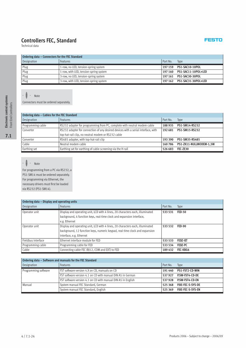
Ordering data – Connectors for the FEC Standard
Designation Features Part No. Type
Plug 1-row, no LED, tension-spring system 197 159 PS1-SAC10-10POL
Plug 1-row, with LED, tension-spring system 197 160 PS1-SAC11-10POL+LED
Plug 3-row, no LED, tension-spring system 197 161 PS1-SAC30-30POL
Plug 3-row, with LED, tension-spring system 197 162 PS1-SAC31-30POL+LED
Ordering data – Cables for the FEC Standard
Designation Features Part No. Type
Programming cable RS232 adapter for programming from PC, complete with neutral modem cable 188 935 PS1-SM14-RS232
Converter RS232 adapter for connection of any desired devices with a serial interface, with
top-hat-rail clip, no neutral modem or RS232 cable
192 681 PS1-SM15-RS232
Converter RS485 adapter, with top-hat-rail clip 193 390 PS1-SM35-RS485
Cable Neutral modem cable 160 786 PS1-ZK11-NULLMODEM-1,5M
Earthing set Earthing set for earthing of cable screening via the H-rail 526 683 FEC-ZE30
Ordering data – Display and operating units
Designation Features Part No. Type
Operator unit Display and operating unit, LCD with 4 lines, 20 characters each, illuminated
background, 4 function keys, real-time clock and expansion interface,
e.g. Ethernet
533 531 FED-50
Operator unit Display and operating unit, LCD with 4 lines, 20 characters each, illuminated
background, 12 function keys, numeric keypad, real-time clock and expansion
interface, e.g. Ethernet
533 532 FED-90
Fieldbus interface Ethernet interface module for FED 533 533 FEDZ-IET
Programming cable Programming cable for FED 533 534 FEDZ-PC
Cable Connecting cable FEC (RJ12, COM and EXT) to FED 189 432 FEC-KBG6
Ordering data – Software and manuals for the FEC Standard
Designation Features Part No. Type
Programming software FST software version 4.X on CD, manuals on CD 191 440 PS1-FST2-CD-WINg g
FST software version 4.1 on CD with manual DIN A5 in German 537 927 P.SW-FST4-CD-DE
FST software version 4.1 on CD with manual DIN A5 in English 537 928 P.SW-FST4-CD-EN
Manual System manual FEC Standard, German 525 368 P.BE-FEC-S-SYS-DE
System manual FEC Standard, English 525 369 P.BE-FEC-S-SYS-EN
Electroniccontrolsystem
s
FrontEndControllers
7.1
-H- Note
Connectors must be ordered separately.
-H- Note
For programming from a PC via RS232, a
PS1-SM14 must be ordered separately.
For programming via Ethernet, the
necessary drivers must first be loaded
via RS232 (PS1-SM14).