Embed Size (px)
DESCRIPTION
Uputstvo za rukovanje.
Citation preview

D155AX-6
SERIAL NUMBER D155AX - 80001 and up
BULLDOZER
Unsafe use of this machine may cause serious injury ordeath. Operators and maintenance personnel must readthis manual before operating or maintaining thismachine. This manual should be kept inside the cab forreference and periodically reviewed by all personnel whowill come into contact with the machine.
Operation & Maintenance Manual
EEAM025000
WARNING


FOREWORD
11
FOREWORD FOREWORD
FOREWORD 1
This manual provides rules and guidelines which will help you use this machine safely and effectively. The pre-cautions in this manual must be followed at all times when performing operation and maintenance. Most accidentsare caused by the failure to follow fundamental safety rules for the operation and maintenance of machines. Acci-dents can be prevented by knowing beforehand conditions that may cause a hazard when performing operationand maintenance.
WARNINGOperators and maintenance personnel must always do as follows before beginning operation or mainte-nance.
Always be sure to read and understand this manual thoroughly before performing operation and mainte-nance.
Read the safety messages given in this manual and the safety labels affixed to the machine thoroughlyand be sure that you understand them fully.
Keep this manual in the storage location for the operation and maintenance manual given below, and haveall personnel read it periodically.
If this manual has been lost or has become dirty and cannot be read, request a replacement manual imme-diately from Komatsu or your Komatsu distributor.
If you sell the machine, be sure to give this manual to the new owners together with the machine.
Komatsu delivers machines that comply with all applicable regulations and standards of the country towhich it has been shipped. If this machine has been purchased in another country or purchased fromsomeone in another country, it may lack certain safety devices and specifications that are necessary foruse in your country. If there is any question about whether your product complies with the applicablestandards and regulations of your country, consult Komatsu or your Komatsu distributor before operatingthe machine.
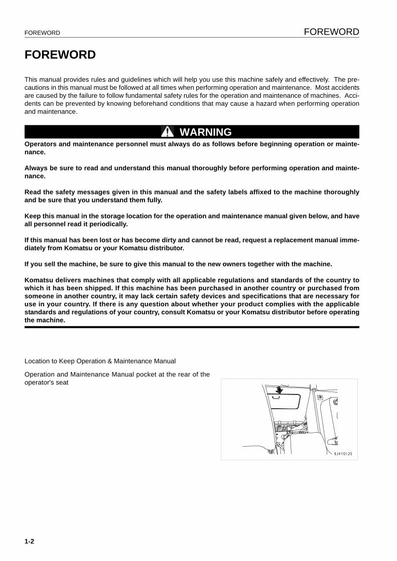
Location to Keep Operation & Maintenance Manual
Operation and Maintenance Manual pocket at the rear of theoperator's seat
1-2
FOREWORD SAFETY INFORMATION
SAFETY INFORMATION 1
To enable you to use this machine safely, safety precautions and labels are given in this manual and affixed to themachine to give explanations of situations involving potential hazards and of the methods of avoiding such situa-tions.
Signal words
The following signal words are used to inform you that there is a potential hazardous situation that may lead to per-sonal injury or damage.
In this manual and on machine labels, the following signal words are used to express the potential level of hazard.
Example of safety message using signal word
WARNINGWhen standing up from the operator's seat, always placethe lock lever in the LOCK position.If you accidentally touch the control levers when they arenot locked, this may cause a serious injury or death.
Other signal words
In addition to the above, the following signal words are used to indicate precautions that should be followed to pro-tect the machine or to give information that is useful to know.
Indicates an imminently hazardous situation which, if not avoided, will result in death or serious injury.
Indicates a potentially hazardous situation which, if not avoided, could result in death or serious injury.
Indicates a potentially hazardous situation which, if not avoided, may result in minor or moderate injury. This word is used also to alert against unsafe practices that may cause property damage.
DANGER
WARNING
CAUTION
NOTICE This word is used for precautions that must be taken to avoid actions which could shorten the life of the machine.
REMARKS This word is used for information that is useful to know.
1-3
SAFETY INFORMATION FOREWORD
q Safety labels
Safety labels are affixed to the machine to inform the operator or maintenance worker on the spot when carryingout operation or maintenance of the machine that may involve hazard.
This machine uses “Safety labels using words“ and “Safety labels using pictograms“ to indicate safety procedures.
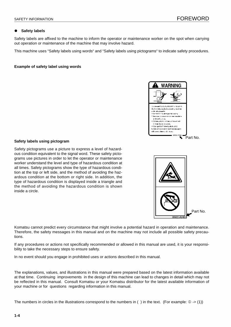
Example of safety label using words
Safety labels using pictogram
Safety pictograms use a picture to express a level of hazard-ous condition equivalent to the signal word. These safety picto-grams use pictures in order to let the operator or maintenanceworker understand the level and type of hazardous condition atall times. Safety pictograms show the type of hazardous condi-tion at the top or left side, and the method of avoiding the haz-ardous condition at the bottom or right side. In addition, thetype of hazardous condition is displayed inside a triangle andthe method of avoiding the hazardous condition is showninside a circle.
Komatsu cannot predict every circumstance that might involve a potential hazard in operation and maintenance.Therefore, the safety messages in this manual and on the machine may not include all possible safety precau-tions.
If any procedures or actions not specifically recommended or allowed in this manual are used, it is your responsi-bility to take the necessary steps to ensure safety.
In no event should you engage in prohibited uses or actions described in this manual.
The explanations, values, and illustrations in this manual were prepared based on the latest information availableat that time. Continuing improvements in the design of this machine can lead to changes in detail which may notbe reflected in this manual. Consult Komatsu or your Komatsu distributor for the latest available information ofyour machine or for questions regarding information in this manual.
The numbers in circles in the illustrations correspond to the numbers in ( ) in the text. (For example: 1 -> (1))
Part No.
Part No.
1-4
FOREWORD SAFETY INFORMATION
Noise emission levels 1
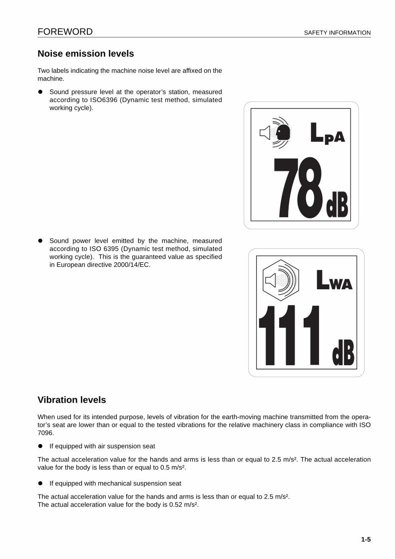
Two labels indicating the machine noise level are affixed on themachine.
q Sound pressure level at the operator’s station, measuredaccording to ISO6396 (Dynamic test method, simulatedworking cycle).
q Sound power level emitted by the machine, measuredaccording to ISO 6395 (Dynamic test method, simulatedworking cycle). This is the guaranteed value as specifiedin European directive 2000/14/EC.
Vibration levels 1
When used for its intended purpose, levels of vibration for the earth-moving machine transmitted from the opera-tor’s seat are lower than or equal to the tested vibrations for the relative machinery class in compliance with ISO7096.
q If equipped with air suspension seat
The actual acceleration value for the hands and arms is less than or equal to 2.5 m/s². The actual accelerationvalue for the body is less than or equal to 0.5 m/s².
q If equipped with mechanical suspension seat
The actual acceleration value for the hands and arms is less than or equal to 2.5 m/s². The actual acceleration value for the body is 0.52 m/s².
1-5
SAFETY INFORMATION FOREWORD
These values were determined using a representative machine and measured during the typical operating condi-tion indicated below according to the measurement procedures that are defined in the standards ISO 2631/1 andISO 5349.
Operating condition:
(TRACTOR DOZER:) Dozing and spreading material throughforward/reversing motion
Guide to Reduce Vibration Levels on Machine 1
The following guides can help an operator of this machine toreduce the whole body vibration levels:
1. Use the correct equipment and attachments.
2. Maintain the machine according to this manual
q Tire pressures (for wheeled machines), tension ofcrawler (for crawler machines)
q Brake and steering systems
q Controls, hydraulic system and linkages
3. Keep the terrain where the machine is working and travel-ing in good condition
q Remove any large rocks or obstacles
q Fill any ditches and holes
q Site manager should provide machine operators withmachine and schedule time to maintain terrain condi-tions
4. Use a seat that meets ISO 7096 and keep the seat main-tained and adjusted
q Adjust the seat and suspension for the weight and sizeof the operator
q Wear seat belt
q Inspect and maintain the seat suspension and adjust-ment mechanisms
5. Steer, brake, accelerate, shift gears (for wheeledmachines), and move the attachment levers and pedalsslowly so that the machine moves smoothly
1-6
FOREWORD SAFETY INFORMATION
6. Adjust the machine speed and travel path to minimize thevibration level
q When pushing with bucket or blade, avoid suddenloading; load gradually
q Drive around obstacles and rough terrain conditions
q Slow down when it is necessary to go over rough ter-rain
q Make the curve radius of traveling path as large aspossible
q Travel at low speed when traveling around sharpcurves
7. Minimize vibrations for long work cycle or long distancetraveling
q Reduce speed to prevent bounce
q Transport machines long distances between worksites
8. The following guidelines can be effective to minimize risksof low back pain
q Operate the machine only when you are in goodhealth.
q Provide breaks to reduce long periods of sitting in thesame posture
q Do not jump down from the cab or machine
q Do not repeatedly handle and lift loads
1-7
INTRODUCTION FOREWORD
INTRODUCTION 1
This Komatsu machine is designed to be used mainly for the following work:
q Dozing
q Cutting into hard or frozen ground or ditching
q Felling trees, removing stumps
q Pushing
q Ripping
For further details, see “WORK POSSIBLE USING BULLDOZER (3-127)“ and “RIPPER OPERATION (3-120)“.
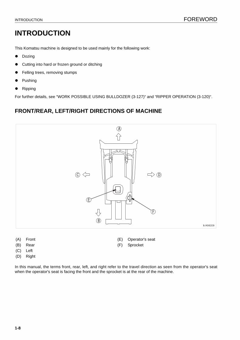
FRONT/REAR, LEFT/RIGHT DIRECTIONS OF MACHINE 1
In this manual, the terms front, rear, left, and right refer to the travel direction as seen from the operator's seatwhen the operator's seat is facing the front and the sprocket is at the rear of the machine.
(A) Front (E) Operator's seat(B) Rear (F) Sprocket(C) Left(D) Right
1-8
FOREWORD INTRODUCTION
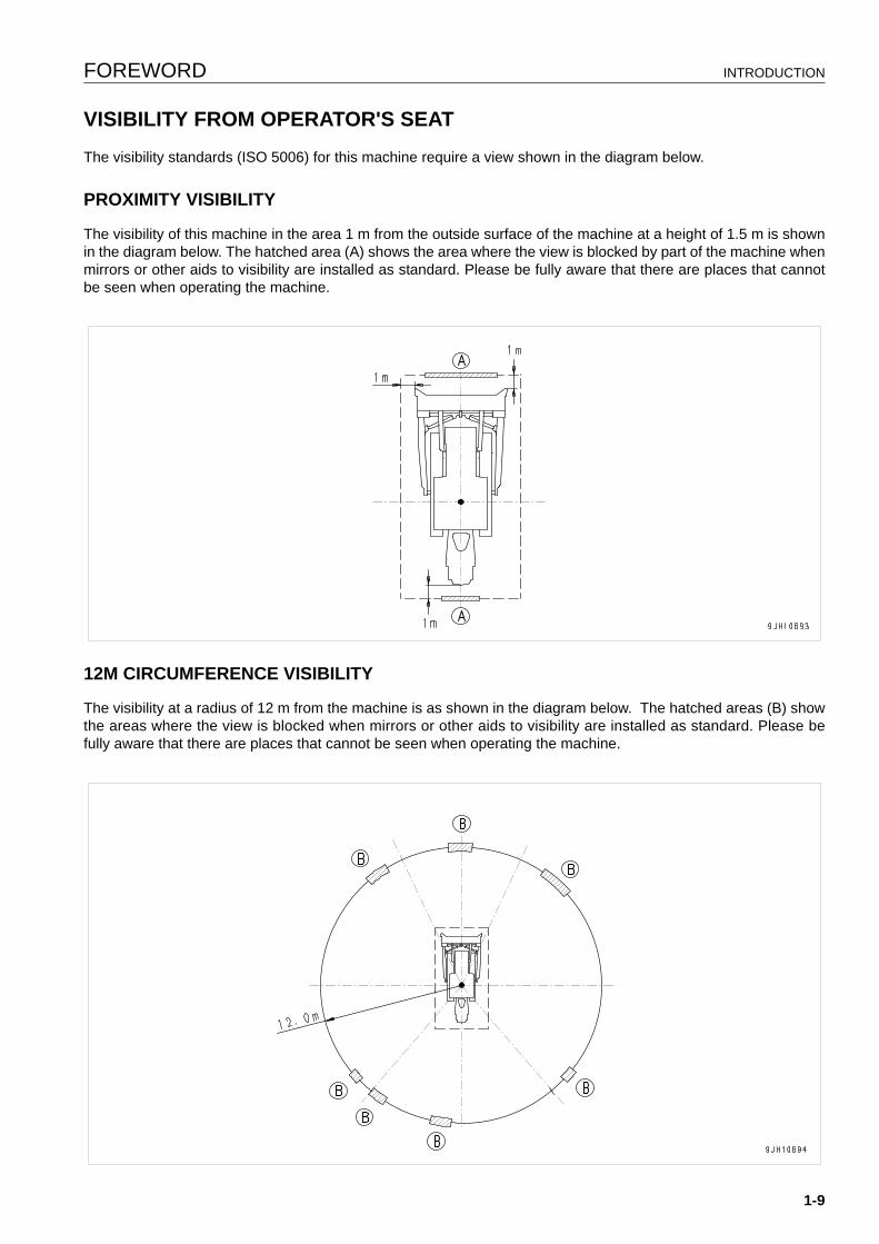
VISIBILITY FROM OPERATOR'S SEAT 1
The visibility standards (ISO 5006) for this machine require a view shown in the diagram below.
PROXIMITY VISIBILITY 1
The visibility of this machine in the area 1 m from the outside surface of the machine at a height of 1.5 m is shownin the diagram below. The hatched area (A) shows the area where the view is blocked by part of the machine whenmirrors or other aids to visibility are installed as standard. Please be fully aware that there are places that cannotbe seen when operating the machine.
12M CIRCUMFERENCE VISIBILITY 1
The visibility at a radius of 12 m from the machine is as shown in the diagram below. The hatched areas (B) showthe areas where the view is blocked when mirrors or other aids to visibility are installed as standard. Please befully aware that there are places that cannot be seen when operating the machine.
1-9
INTRODUCTION FOREWORD
BREAKING IN THE MACHINE 1
NOTICEYour Komatsu machine has been thoroughly adjusted and tested before shipment from the factory. How-ever, operating the machine under full load before breaking the machine in can adversely affect the perfor-mance and shorten the machine life.Be sure to break in the machine for the initial 100 hours (as indicated on the service meter).
Make sure that you fully understand the content of this manual, and pay careful attention to the following pointswhen breaking in the machine.
q Run the engine at idle for 15 seconds after starting it. During this time, do not operate the control levers or fuelcontrol dial.
q Idle the engine for 5 minutes after starting it up.
q Avoid operation with heavy loads or at high speeds.
q Immediately after starting the engine, avoid sudden starts, sudden acceleration, unnecessary sudden stops,and sudden changes in direction.
1-10
FOREWORD NECESSARY INFORMATION
NECESSARY INFORMATION 1
When requesting service or ordering replacement parts, please inform your Komatsu distributor of the followingitems.
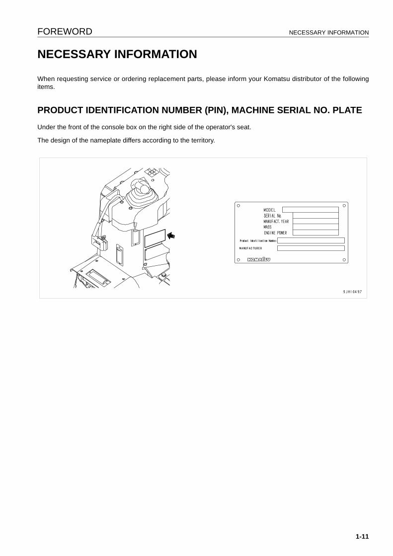
PRODUCT IDENTIFICATION NUMBER (PIN), MACHINE SERIAL NO. PLATE 1
Under the front of the console box on the right side of the operator's seat.
The design of the nameplate differs according to the territory.
1-11
NECESSARY INFORMATION FOREWORD
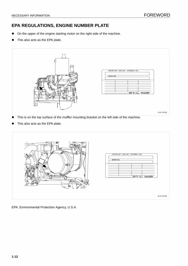
EPA REGULATIONS, ENGINE NUMBER PLATE 1
q On the upper of the engine starting motor on the right side of the machine.
q This also acts as the EPA plate.
q This is on the top surface of the muffler mounting bracket on the left side of the machine.
q This also acts as the EPA plate.
EPA: Environmental Protection Agency, U.S.A.
1-12
FOREWORD NECESSARY INFORMATION
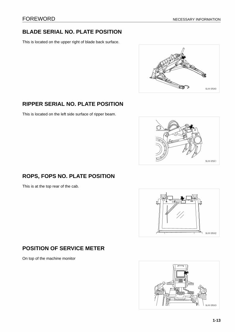
BLADE SERIAL NO. PLATE POSITION 1
This is located on the upper right of blade back surface.
RIPPER SERIAL NO. PLATE POSITION 1
This is located on the left side surface of ripper beam.
ROPS, FOPS NO. PLATE POSITION 1
This is at the top rear of the cab.
POSITION OF SERVICE METER 1
On top of the machine monitor
1-13
NECESSARY INFORMATION FOREWORD
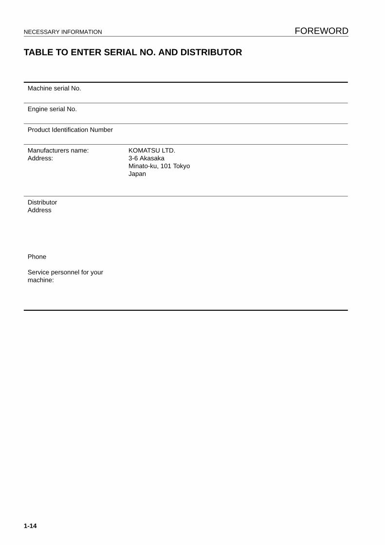
TABLE TO ENTER SERIAL NO. AND DISTRIBUTOR 1
Machine serial No.
Engine serial No.
Product Identification Number
Manufacturers name:Address:
KOMATSU LTD.3-6 AkasakaMinato-ku, 101 TokyoJapan
DistributorAddress
Phone
Service personnel for your machine:
1-14
FOREWORD NECESSARY INFORMATION
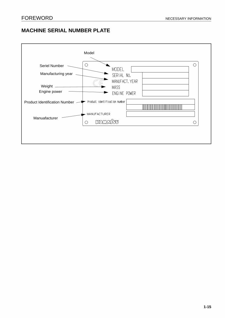
MACHINE SERIAL NUMBER PLATE
Model
Seriel Number
Manufacturing year
WeightEngine power
Product Identification Number
Manuafacturer
1-15

NECESSARY INFORMATION FOREWORD
1-16
CONTENTS
CONTENTS
FOREWORD
FOREWORD......................................................................................................................................................... 1-2
SAFETY INFORMATION...................................................................................................................................... 1-3
Noise emission levels ................................................................................................................................. 1-5Vibration levels............................................................................................................................................ 1-5
Guide to Reduce Vibration Levels on Machine.................................................................................. 1-6
INTRODUCTION................................................................................................................................................... 1-8
FRONT/REAR, LEFT/RIGHT DIRECTIONS OF MACHINE....................................................................... 1-8VISIBILITY FROM OPERATOR'S SEAT.................................................................................................... 1-9
PROXIMITY VISIBILITY .................................................................................................................... 1-912M CIRCUMFERENCE VISIBILITY ................................................................................................ 1-9
BREAKING IN THE MACHINE................................................................................................................. 1-10
NECESSARY INFORMATION ........................................................................................................................... 1-11
PRODUCT IDENTIFICATION NUMBER (PIN), MACHINE SERIAL NO. PLATE .................................... 1-11EPA REGULATIONS, ENGINE NUMBER PLATE ................................................................................... 1-12BLADE SERIAL NO. PLATE POSITION .................................................................................................. 1-13RIPPER SERIAL NO. PLATE POSITION................................................................................................. 1-13ROPS, FOPS NO. PLATE POSITION...................................................................................................... 1-13POSITION OF SERVICE METER ............................................................................................................ 1-13TABLE TO ENTER SERIAL NO. AND DISTRIBUTOR ............................................................................ 1-14MACHINE SERIAL NUMBER PLATE....................................................................................................... 1-15
SAFETY
SAFETY ................................................................................................................................................................ 2-2
SAFETY LABELS................................................................................................................................................. 2-4
POSITIONS OF SAFETY PICTOGRAMS .................................................................................................. 2-4SAFETY LABELS ....................................................................................................................................... 2-5
GENERAL PRECAUTIONS ................................................................................................................................. 2-9
PRECAUTIONS FOR OPERATION ................................................................................................................... 2-18
BEFORE STARTING ENGINE ................................................................................................................. 2-18OPERATION............................................................................................................................................. 2-19TRANSPORTATION................................................................................................................................. 2-23BATTERY ................................................................................................................................................. 2-24TOWING ................................................................................................................................................... 2-26
PRECAUTIONS FOR MAINTENANCE.............................................................................................................. 2-27
1-17
CONTENTS
OPERATION
GENERAL VIEW .................................................................................................................................................. 3-2
GENERAL VIEW OF MACHINE ................................................................................................................. 3-2GENERAL VIEW OF CONTROLS AND GAUGES..................................................................................... 3-3
EXPLANATION OF COMPONENTS.................................................................................................................... 3-5
MACHINE MONITOR ................................................................................................................................. 3-5BASIC OPERATION OF MACHINE MONITOR ................................................................................ 3-6BASIC CHECK MONITORS .............................................................................................................. 3-9CAUTION MONITORS .................................................................................................................... 3-10EMERGENCY MONITORS ............................................................................................................. 3-12METER DISPLAY PORTION........................................................................................................... 3-14MONITOR SWITCHES PORTION .................................................................................................. 3-21HANDLING FUNCTION SWITCHES............................................................................................... 3-26SPEED RANGE DISPLAY............................................................................................................... 3-48
SWITCHES ............................................................................................................................................... 3-49CONTROL LEVERS, PEDALS ................................................................................................................. 3-53DUST INDICATOR ................................................................................................................................... 3-61FUSE BOX................................................................................................................................................ 3-61
CIRCUIT BREAKER ........................................................................................................................ 3-63CIRCUIT BREAKER FOR MAIN POWER SUPPLY........................................................................ 3-63FUSE CAPACITY AND NAME OF CIRCUIT................................................................................... 3-64
DOOR POCKET ....................................................................................................................................... 3-65ASHTRAY ................................................................................................................................................. 3-65HANDLING AIR CONDITIONER .............................................................................................................. 3-66
GENERAL LOCATIONS OF CONTROL PANEL ............................................................................ 3-66METHOD OF OPERATION ............................................................................................................. 3-70PRECAUTIONS WHEN USING AIR CONDITIONER ..................................................................... 3-76INSPECTION AND MAINTENANCE OF AIR CONDITIONER EQUIPPED MACHINE................... 3-77
OPERATION ....................................................................................................................................................... 3-78
CHECK BEFORE STARTING ENGINE, ADJUST.................................................................................... 3-78WALK-AROUND CHECK ................................................................................................................ 3-78CHECK BEFORE STARTING ......................................................................................................... 3-79ADJUSTMENT................................................................................................................................. 3-89OPERATIONS AND CHECKS BEFORE STARTING ENGINE....................................................... 3-93
STARTING ENGINE ................................................................................................................................. 3-95NORMAL STARTING ...................................................................................................................... 3-95STARTING IN COLD WEATHER .................................................................................................... 3-97
OPERATIONS AND CHECKS AFTER STARTING ENGINE ................................................................. 3-100WARMING UP OPERATIONS ...................................................................................................... 3-100IN COLD AREAS ........................................................................................................................... 3-101
STOPPING ENGINE............................................................................................................................... 3-102MOVING MACHINE................................................................................................................................ 3-103STOPPING MACHINE............................................................................................................................ 3-105SHIFTING GEAR .................................................................................................................................... 3-106SHIFTING BETWEEN FORWARD AND REVERSE .............................................................................. 3-112
1-18
CONTENTS
STEERING MACHINE............................................................................................................................ 3-114NORMAL TURNING...................................................................................................................... 3-114TURNING WHILE DESCENDING A SLOPE................................................................................. 3-115
PRECAUTIONS FOR OPERATION ....................................................................................................... 3-116PAY ATTENTION TO GAUGES.................................................................................................... 3-116PERMISSIBLE WATER DEPTH.................................................................................................... 3-116PRECAUTIONS WHEN TRAVELING UP OR DOWN HILLS........................................................ 3-116PRECAUTIONS ON SLOPE ......................................................................................................... 3-116METHOD OF USING BRAKES ..................................................................................................... 3-117PROHIBITED TO KEEP THE DOOR OPEN DURING OPERATIONS ......................................... 3-117IT IS PROHIBITED TO MODIFY THE CAB GLASS IN ANY WAY THAT WILL OBSTRUCT THE VIEW3-117
PARKING MACHINE .............................................................................................................................. 3-118CHECK AFTER STOPPING ENGINE .................................................................................................... 3-119CHECK AFTER FINISHING WORK ....................................................................................................... 3-120LOCKING................................................................................................................................................ 3-120RIPPER OPERATION ............................................................................................................................ 3-120
EFFECTIVE METHOD OF USE.................................................................................................... 3-120DIGGING UP BOULDERS OR ROCKBED ................................................................................... 3-121OPERATING ON SLOPES............................................................................................................ 3-121METHOD OF OPERATING PIN PULLER..................................................................................... 3-122
OPERATING METHOD FOR RIPPING OPERATIONS ......................................................................... 3-123BASIC OPERATING METHOD ..................................................................................................... 3-123RIPPING BY CLIFFS..................................................................................................................... 3-124RIPPING BY SLOPE FACES ........................................................................................................ 3-124DIGGING UP BOULDERS ............................................................................................................ 3-125PRECAUTIONS WHEN RIPPING................................................................................................. 3-126
WORK POSSIBLE USING BULLDOZER............................................................................................... 3-127DOZING......................................................................................................................................... 3-127SMOOTHING................................................................................................................................. 3-128CUTTING INTO HARD OR FROZEN GROUND OR DITCHING.................................................. 3-128FELLING TREES, REMOVING STUMPS ..................................................................................... 3-128PUSHER OPERATIONS ............................................................................................................... 3-129
ADJUSTING POSTURE OF WORK EQUIPMENT................................................................................. 3-129BLADE ADJUSTMENT.................................................................................................................. 3-129METHOD OF ANGLING BLADE ................................................................................................... 3-131ADJUSTING TILT AMOUNT ......................................................................................................... 3-132ADJUSTING RIPPER.................................................................................................................... 3-134ADJUST ANGLE OF BLADE EDGE.............................................................................................. 3-135
TIPS FOR LONGER UNDERCARRIAGE LIFE...................................................................................... 3-136OPERATION METHOD................................................................................................................. 3-136INSPECTION AND ADJUSTING................................................................................................... 3-137INSPECTION AND REPAIR.......................................................................................................... 3-137
TRANSPORTATION......................................................................................................................................... 3-139
LOADING, UNLOADING WORK ............................................................................................................ 3-139LOADING....................................................................................................................................... 3-139SECURING MACHINE .................................................................................................................. 3-140
1-19
CONTENTS
UNLOADING ................................................................................................................................. 3-141METHOD OF LIFTING MACHINE .......................................................................................................... 3-142PRECAUTIONS FOR TRANSPORTATION ........................................................................................... 3-144TRAVELING ON ROADS ....................................................................................................................... 3-144REMOVAL OF CAB ................................................................................................................................ 3-145
COLD WEATHER OPERATION ...................................................................................................................... 3-147
PRECAUTIONS FOR LOW TEMPERATURE ........................................................................................ 3-147FUEL AND LUBRICANTS ............................................................................................................. 3-147COOLANT ..................................................................................................................................... 3-147BATTERY ...................................................................................................................................... 3-148
AFTER COMPLETION OF WORK ......................................................................................................... 3-149AFTER COLD WEATHER ...................................................................................................................... 3-149
LONG-TERM STORAGE.................................................................................................................................. 3-150
BEFORE STORAGE............................................................................................................................... 3-150DURING STORAGE ............................................................................................................................... 3-150AFTER STORAGE.................................................................................................................................. 3-150
TROUBLESHOOTING...................................................................................................................................... 3-151
AFTER RUNNING OUT OF FUEL.......................................................................................................... 3-151PROCEDURE FOR BLEEDING AIR ............................................................................................. 3-151
METHOD OF TOWING MACHINE ......................................................................................................... 3-153IF BATTERY IS DISCHARGED.............................................................................................................. 3-154
REMOVAL AND INSTALLATION OF BATTERY .......................................................................... 3-154PRECAUTIONS WHEN CHARGING BATTERY........................................................................... 3-155STARTING ENGINE WITH BOOSTER CABLE ............................................................................ 3-155
OTHER TROUBLE ................................................................................................................................. 3-158ELECTRICAL SYSTEM................................................................................................................. 3-158ELECTRONIC CONTROL SYSTEM ............................................................................................. 3-159CHASSIS ....................................................................................................................................... 3-160ENGINE ......................................................................................................................................... 3-161POINT OF CONTACT TO TELEPHONE WHEN ERROR OCCURS ............................................ 3-162
MAINTENANCE
GUIDES TO MAINTENANCE ............................................................................................................................... 4-2
OUTLINES OF SERVICE ..................................................................................................................................... 4-5
HANDLING OIL, FUEL, COOLANT, AND PERFORMING OIL CLINIC...................................................... 4-5OIL ..................................................................................................................................................... 4-5FUEL.................................................................................................................................................. 4-6COOLANT AND WATER FOR DILUTION......................................................................................... 4-6GREASE............................................................................................................................................ 4-7CARRYING OUT KOWA (Komatsu Oil Wear Analysis) .................................................................... 4-7STORING OIL AND FUEL................................................................................................................. 4-8FILTERS ............................................................................................................................................ 4-8
OUTLINE OF ELECTRIC SYSTEM............................................................................................................ 4-8
1-20
CONTENTS
WEAR PARTS LIST ........................................................................................................................................... 4-10
WEAR PARTS LIST.................................................................................................................................. 4-10
RECOMMENDED FUEL, COOLANT, AND LUBRICANT ................................................................................. 4-12
RECOMMENDED BRANDS, RECOMMENDED QUALITY FOR PRODUCTS OTHER THAN KOMATSU GENUINE OIL........................................................................................................................................... 4-14
STANDARD TIGHTENING TORQUES FOR BOLTS AND NUTS..................................................................... 4-15
TORQUE LIST.......................................................................................................................................... 4-15
PERIODIC REPLACEMENT OF SAFETY CRITICAL PARTS .......................................................................... 4-16
SAFETY CRITICAL PARTS...................................................................................................................... 4-16
MAINTENANCE SCHEDULE CHART ............................................................................................................... 4-18
MAINTENANCE SCHEDULE CHART...................................................................................................... 4-18INITIAL 250 HOURS SERVICE (ONLY AFTER THE FIRST 250 HOURS) .................................... 4-18WHEN REQUIRED.......................................................................................................................... 4-18CHECK BEFORE STARTING ......................................................................................................... 4-18EVERY 250 HOURS SERVICE....................................................................................................... 4-18EVERY 500 HOURS SERVICE....................................................................................................... 4-18EVERY 1000 HOURS SERVICE..................................................................................................... 4-19EVERY 2000 HOURS SERVICE..................................................................................................... 4-19EVERY 4000 HOURS SERVICE..................................................................................................... 4-19EVERY 8000 HOURS SERVICE..................................................................................................... 4-19
SERVICE PROCEDURE .................................................................................................................................... 4-20
INITIAL 250 HOURS SERVICE (ONLY AFTER THE FIRST 250 HOURS) ............................................. 4-20WHEN REQUIRED................................................................................................................................... 4-20CHECK BEFORE STARTING .................................................................................................................. 4-39EVERY 250 HOURS SERVICE................................................................................................................ 4-40EVERY 500 HOURS SERVICE................................................................................................................ 4-48EVERY 1000 HOURS SERVICE.............................................................................................................. 4-55EVERY 2000 HOURS SERVICE.............................................................................................................. 4-65EVERY 4000 HOURS SERVICE.............................................................................................................. 4-72EVERY 8000 HOURS SERVICE.............................................................................................................. 4-76
SPECIFICATIONS
SPECIFICATIONS ................................................................................................................................................ 5-2
ATTACHMENTS, OPTIONS
GENERAL PRECAUTIONS ................................................................................................................................. 6-2
PRECAUTIONS RELATED TO SAFETY ................................................................................................... 6-2
INTRODUCTION OF ATTACHMENTS AND OPTIONS ...................................................................................... 6-3
INTRODUCTION OF ATTACHMENTS AND OPTIONS............................................................................. 6-3
1-21

CONTENTS
HEADREST, HANDLING ..................................................................................................................................... 6-4
CAP WITH LOCK, HANDLING ............................................................................................................................ 6-5
METHOD OF OPENING AND CLOSING CAP WITH LOCK...................................................................... 6-5
PROCEDURE FOR SELECTING RIPPER POINT............................................................................................... 6-6
PROCEDURE FOR SELECTING RIPPER POINT..................................................................................... 6-6
HANDLING MACHINES EQUIPPED WITH KOMTRAX ...................................................................................... 6-7
BASIC PRECAUTIONS .............................................................................................................................. 6-7
INDEX
COLOPHON
1-22

SAFETY
12
WARNINGPlease be sure that you fully understand this manual and theprecautions discribed in this manual and the safety labelson the machine. When operating or servicing the machine,always follow these precaustions strictly.
SAFETY SAFETY
SAFETY 2
Safety Labels ...................................................................................................................................................... 2-42 Positions of Safety Pictograms .................................................................................................................... 2-42 Safety Labels ............................................................................................................................................... 2-52
General Precautions
Safety Rules................................................................................................................................................. 2-92 If Abnormalities are Found ........................................................................................................................... 2-92 Clothing and Personal Protective Items....................................................................................................... 2-92 Fire Extinguisher and First Aid Kit................................................................................................................ 2-92 Safety Features.......................................................................................................................................... 2-102 Keep Machine Clean.................................................................................................................................. 2-102 Inside Operator's Compartment ................................................................................................................. 2-102 Always Apply Lock when Leaving Operator's Seat .................................................................................... 2-102 Handrails and Steps................................................................................................................................... 2-112 Mounting and Dismounting ........................................................................................................................ 2-122 No People on Attachments ........................................................................................................................ 2-122 Prevention of Burns.................................................................................................................................... 2-122 Fire Prevention........................................................................................................................................... 2-122 Action if Fire Occurs................................................................................................................................... 2-132 Window Washer Liquid .............................................................................................................................. 2-132 Precautions when Using ROPS ................................................................................................................. 2-142 Precautions for Attachments ...................................................................................................................... 2-142 Unauthorized Modification.......................................................................................................................... 2-142 Safety at Worksite ...................................................................................................................................... 2-152 Working on Loose Ground ......................................................................................................................... 2-152 Do not Go Close to High-Voltage Cables................................................................................................... 2-152 Ensure Good Visibility ................................................................................................................................ 2-162 Ventilation for Enclosed Areas ................................................................................................................... 2-162 Checking Signalman's Signals and Signs.................................................................................................. 2-162 Be Careful About Asbestos Dust................................................................................................................ 2-172
Precautions for Operation ................................................................................................................................. 2-182 Before Starting Engine ............................................................................................................................... 2-182
Checks Before Starting Engine........................................................................................................... 2-182 Precautions when Starting .................................................................................................................. 2-182 Precautions in Cold Areas .................................................................................................................. 2-192
Operation ................................................................................................................................................... 2-192 Checks Before Operation.................................................................................................................... 2-192 Precautions for Moving Machine Forward or in Reverse .................................................................... 2-202 Precautions when Traveling................................................................................................................ 2-202 Traveling on Slopes ............................................................................................................................ 2-212 Prohibited Operations ......................................................................................................................... 2-212 Using Brakes....................................................................................................................................... 2-212 Operate Carefully on Snow................................................................................................................. 2-222 Parking Machine ................................................................................................................................. 2-222
Transportation ............................................................................................................................................ 2-232 Shipping .............................................................................................................................................. 2-232
Battery........................................................................................................................................................ 2-242 Battery Hazard Prevention.................................................................................................................. 2-242 Starting with Booster Cable ................................................................................................................ 2-252
Towing........................................................................................................................................................ 2-262 When Towing ...................................................................................................................................... 2-262
2-2

SAFETY SAFETY
Precautions for Maintenance ............................................................................................................................ 2-272 Warning Tag .............................................................................................................................................. 2-272 Keep Work Place Clean and Tidy .............................................................................................................. 2-272 Appoint Leader when Working with Others................................................................................................ 2-272 Stop Engine Before Carrying Out Inspection and Maintenance ................................................................ 2-282 Two Workers for Maintenance when Engine is Running ........................................................................... 2-282 Proper Tools .............................................................................................................................................. 2-292 Handling Accumulator................................................................................................................................ 2-292 Personnel................................................................................................................................................... 2-292 Attachments ............................................................................................................................................... 2-302 Work Under the Machine ........................................................................................................................... 2-302 Noise.......................................................................................................................................................... 2-302 Precautions when Using Hammer ............................................................................................................. 2-302 Repair Welding .......................................................................................................................................... 2-302 Removing Battery Terminal ....................................................................................................................... 2-312 Precautions when Using High-Pressure Grease to Adjust Track Tension................................................. 2-312 Do not Disassemble Recoil Spring ............................................................................................................ 2-312 Precaution with High-Pressure Oil ............................................................................................................. 2-312 Precaution for High Fuel Pressure............................................................................................................. 2-322 Handing High-Pressure Hoses .................................................................................................................. 2-322 Precaution for High Voltage ....................................................................................................................... 2-322 Waste Material ........................................................................................................................................... 2-332 Maintenance for Air Conditioner ................................................................................................................ 2-332 Compressed Air ......................................................................................................................................... 2-332 Periodic Replacement of Safety Critical Parts ........................................................................................... 2-332
2-3
SAFETY LABELS SAFETY
SAFETY LABELS 2
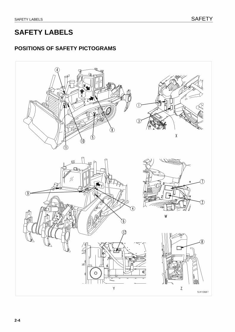
POSITIONS OF SAFETY PICTOGRAMS 2
2-4
SAFETY SAFETY LABELS
SAFETY LABELS 2
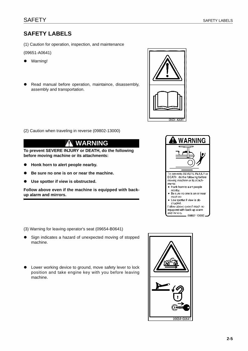
(1) Caution for operation, inspection, and maintenance
(09651-A0641)
q Warning!
q Read manual before operation, maintaince, disassembly,assembly and transportation.
(2) Caution when traveling in reverse (09802-13000)
WARNINGTo prevent SEVERE INJURY or DEATH, do the following before moving machine or its attachments:
q Honk horn to alert people nearby.
q Be sure no one is on or near the machine.
q Use spotter if view is obstructed.
Follow above even if the machine is equipped with back-up alarm and mirrors.
(3) Warning for leaving operator's seat (09654-B0641)
q Sign indicates a hazard of unexpected moving of stoppedmachine.
q Lower working device to ground, move safety lever to lockposition and take engine key with you before leavingmachine.
2-5
SAFETY LABELS SAFETY
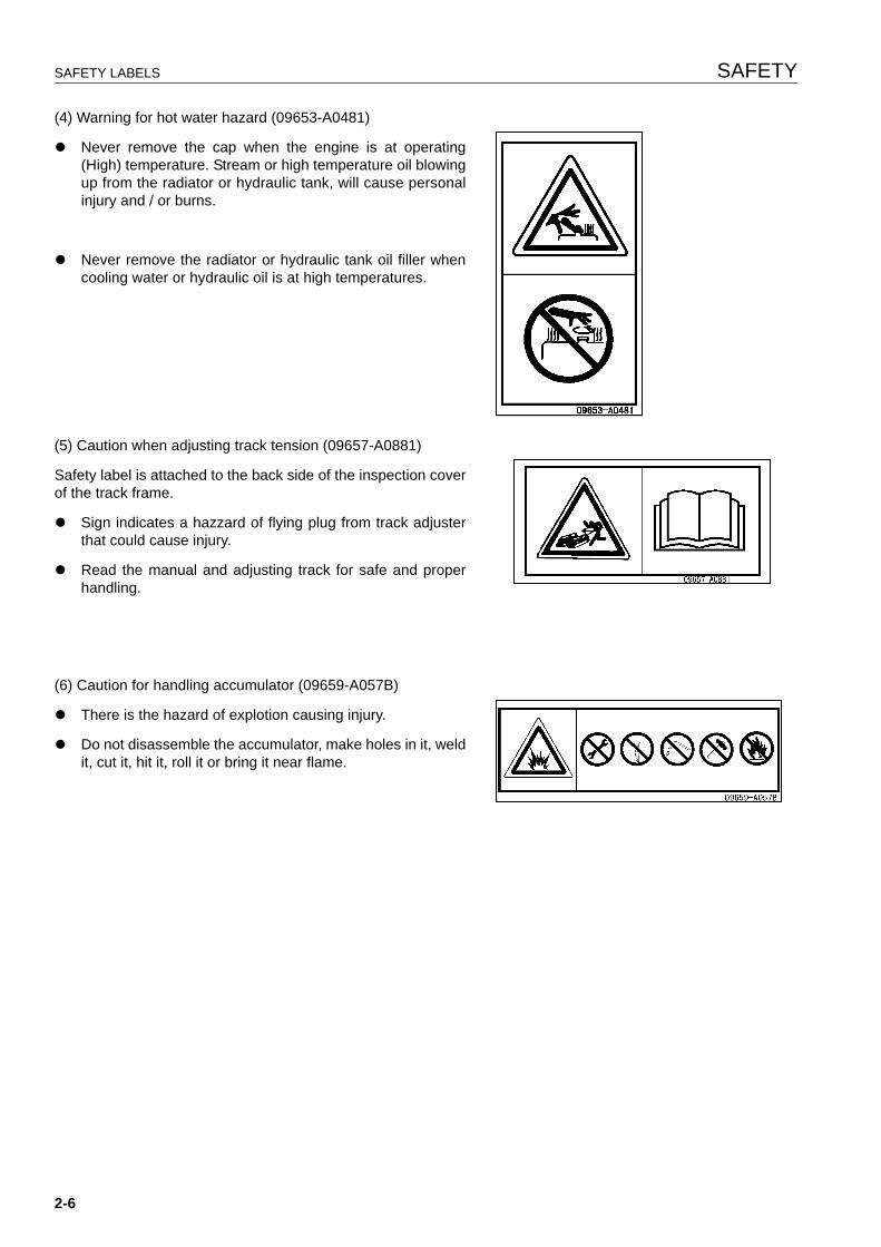
(4) Warning for hot water hazard (09653-A0481)
q Never remove the cap when the engine is at operating(High) temperature. Stream or high temperature oil blowingup from the radiator or hydraulic tank, will cause personalinjury and / or burns.
q Never remove the radiator or hydraulic tank oil filler whencooling water or hydraulic oil is at high temperatures.
(5) Caution when adjusting track tension (09657-A0881)
Safety label is attached to the back side of the inspection coverof the track frame.
q Sign indicates a hazzard of flying plug from track adjusterthat could cause injury.
q Read the manual and adjusting track for safe and properhandling.
(6) Caution for handling accumulator (09659-A057B)
q There is the hazard of explotion causing injury.
q Do not disassemble the accumulator, make holes in it, weldit, cut it, hit it, roll it or bring it near flame.
2-6
SAFETY SAFETY LABELS
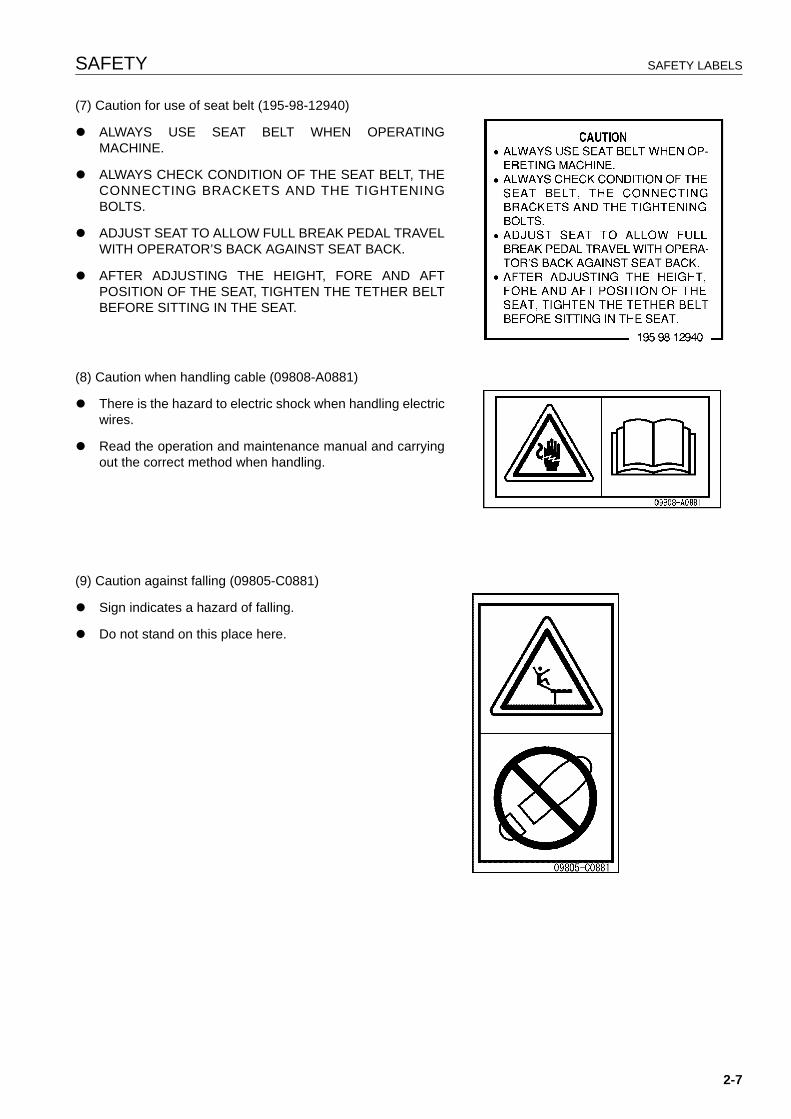
(7) Caution for use of seat belt (195-98-12940)
q ALWAYS USE SEAT BELT WHEN OPERATINGMACHINE.
q ALWAYS CHECK CONDITION OF THE SEAT BELT, THECONNECTING BRACKETS AND THE TIGHTENINGBOLTS.
q ADJUST SEAT TO ALLOW FULL BREAK PEDAL TRAVELWITH OPERATOR’S BACK AGAINST SEAT BACK.
q AFTER ADJUSTING THE HEIGHT, FORE AND AFTPOSITION OF THE SEAT, TIGHTEN THE TETHER BELTBEFORE SITTING IN THE SEAT.
(8) Caution when handling cable (09808-A0881)
q There is the hazard to electric shock when handling electricwires.
q Read the operation and maintenance manual and carryingout the correct method when handling.
(9) Caution against falling (09805-C0881)
q Sign indicates a hazard of falling.
q Do not stand on this place here.
2-7
SAFETY LABELS SAFETY
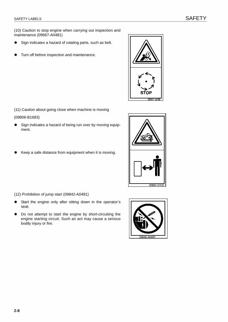
(10) Caution to stop engine when carrying out inspection andmaintenance (09667-A0481)
q Sign indicates a hazard of rotating parts, such as belt.
q Turn off before inspection and maintenance.
(11) Caution about going close when machine is moving
(09806-B1683)
q Sign indicates a hazard of being run over by moving equip-ment.
q Keep a safe distance from equipment when it is moving.
(12) Prohibition of jump start (09842-A0481)
q Start the engine only after sitting down in the operator’sseat.
q Do not attempt to start the engine by short-circuiting theengine starting circuit. Such an act may cause a seriousbodily injury or fire.
2-8
SAFETY GENERAL PRECAUTIONS
GENERAL PRECAUTIONS 2
SAFETY RULES
q Only trained and authorized personnel can operate and maintain the machine.
q Follow all safety rules, precautions and instructions when operating or performing maintenance on themachine.
q If you are under the influence of alcohol or medication, your ability to safely operate or repair your machinemay be severly impaired putting yourself and everyone else on your jobsite in danger.
q When working with another operator or with a person on worksite traffic duty, be sure that all personnel under-stand all hand signals that are to be used.
IF ABNORMALITIES ARE FOUND
If you find any problems in the machine during operation or maintenance (noise, vibration, smell, incorrect gauges,smoke, oil leakage, etc., or any abnormal display on the warning devices or monitor), report to the person incharge and have the necessary action taken. Do not operate the machine until the problem has been corrected.
CLOTHING AND PERSONAL PROTECTIVE ITEMS
q Do not wear loose clothing and accessories. There is a hazard that they may catch on control levers or otherprotruding parts.
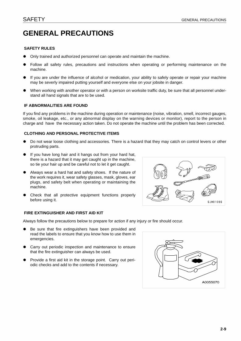
q If you have long hair and it hangs out from your hard hat,there is a hazard that it may get caught up in the machine,so tie your hair up and be careful not to let it get caught.
q Always wear a hard hat and safety shoes. If the nature ofthe work requires it, wear safety glasses, mask, gloves, earplugs, and safety belt when operating or maintaining themachine.
q Check that all protective equipment functions properlybefore using it.
FIRE EXTINGUISHER AND FIRST AID KIT
Always follow the precautions below to prepare for action if any injury or fire should occur.
q Be sure that fire extinguishers have been provided andread the labels to ensure that you know how to use them inemergencies.
q Carry out periodic inspection and maintenance to ensurethat the fire extinguisher can always be used.
q Provide a first aid kit in the storage point. Carry out peri-odic checks and add to the contents if necessary.
2-9
GENERAL PRECAUTIONS SAFETY
SAFETY FEATURES
q Be sure that all guards and covers are in their proper position. Have guards and covers repaired immediately ifthey are damaged.
q Understand the method of use of safety features and use them properly.
q Never remove any safety features. Always keep them in good operating condition.
KEEP MACHINE CLEAN
q If water gets into the electrical system, there is a hazard that it will cause malfunctions or misoperation. Do notuse water or steam to wash the electrical system (sensors, connectors).
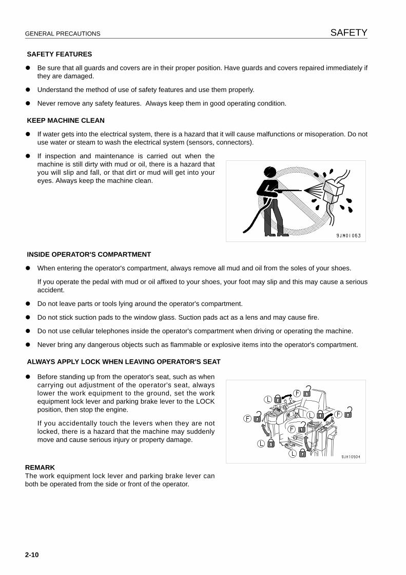
q If inspection and maintenance is carried out when themachine is still dirty with mud or oil, there is a hazard thatyou will slip and fall, or that dirt or mud will get into youreyes. Always keep the machine clean.
INSIDE OPERATOR'S COMPARTMENT
q When entering the operator's compartment, always remove all mud and oil from the soles of your shoes.
If you operate the pedal with mud or oil affixed to your shoes, your foot may slip and this may cause a seriousaccident.
q Do not leave parts or tools lying around the operator's compartment.
q Do not stick suction pads to the window glass. Suction pads act as a lens and may cause fire.
q Do not use cellular telephones inside the operator's compartment when driving or operating the machine.
q Never bring any dangerous objects such as flammable or explosive items into the operator's compartment.
ALWAYS APPLY LOCK WHEN LEAVING OPERATOR'S SEAT
q Before standing up from the operator's seat, such as whencarrying out adjustment of the operator's seat, alwayslower the work equipment to the ground, set the workequipment lock lever and parking brake lever to the LOCKposition, then stop the engine.
If you accidentally touch the levers when they are notlocked, there is a hazard that the machine may suddenlymove and cause serious injury or property damage.
REMARKThe work equipment lock lever and parking brake lever canboth be operated from the side or front of the operator.
2-10
SAFETY GENERAL PRECAUTIONS
q When leaving the machine, always lower the work equip-ment completely to the ground, set work equipment locklever and parking lever securely to the LOCK position, thenstop the engine. Use the key to lock all the equipment.Always remove the key, take it with you, and keep it in thespecified place.
HANDRAILS AND STEPS
To prevent personal injury caused by slipping or falling off the machine, always do as follows.
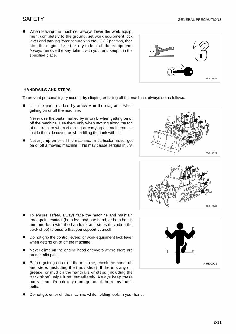
q Use the parts marked by arrow A in the diagrams whengetting on or off the machine.
Never use the parts marked by arrow B when getting on oroff the machine. Use them only when moving along the topof the track or when checking or carrying out maintenanceinside the side cover, or when filling the tank with oil.
q Never jump on or off the machine. In particular, never geton or off a moving machine. This may cause serious injury.
q To ensure safety, always face the machine and maintainthree-point contact (both feet and one hand, or both handsand one foot) with the handrails and steps (including thetrack shoe) to ensure that you support yourself.
q Do not grip the control levers, or work equipment lock leverwhen getting on or off the machine.
q Never climb on the engine hood or covers where there areno non-slip pads.
q Before getting on or off the machine, check the handrailsand steps (including the track shoe). If there is any oil,grease, or mud on the handrails or steps (including thetrack shoe), wipe it off immediately. Always keep theseparts clean. Repair any damage and tighten any loosebolts.
q Do not get on or off the machine while holding tools in your hand.
2-11
GENERAL PRECAUTIONS SAFETY
MOUNTING AND DISMOUNTING
q Never jump on or off the machine. Never get on or off a moving machine.q If the machine starts to move when there is no operator on the machine, do not jump on to the machine and try
to stop it.
NO PEOPLE ON ATTACHMENTS
Never let anyone ride on the work equipment, or other attachments. There is a hazard of falling and suffering seri-ous injury.
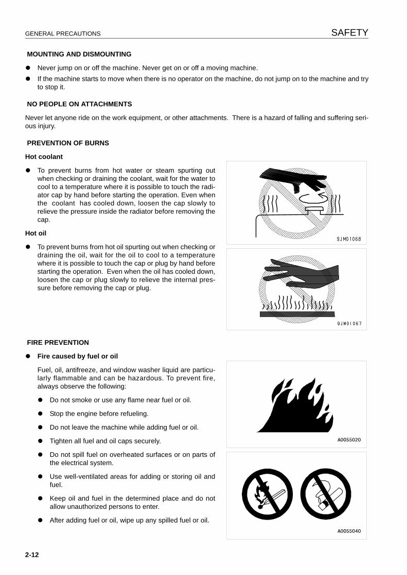
PREVENTION OF BURNS
Hot coolant
q To prevent burns from hot water or steam spurting outwhen checking or draining the coolant, wait for the water tocool to a temperature where it is possible to touch the radi-ator cap by hand before starting the operation. Even whenthe coolant has cooled down, loosen the cap slowly torelieve the pressure inside the radiator before removing thecap.
Hot oil
q To prevent burns from hot oil spurting out when checking ordraining the oil, wait for the oil to cool to a temperaturewhere it is possible to touch the cap or plug by hand beforestarting the operation. Even when the oil has cooled down,loosen the cap or plug slowly to relieve the internal pres-sure before removing the cap or plug.
FIRE PREVENTION
q Fire caused by fuel or oil
Fuel, oil, antifreeze, and window washer liquid are particu-larly flammable and can be hazardous. To prevent fire,always observe the following:
q Do not smoke or use any flame near fuel or oil.
q Stop the engine before refueling.
q Do not leave the machine while adding fuel or oil.
q Tighten all fuel and oil caps securely.
q Do not spill fuel on overheated surfaces or on parts ofthe electrical system.
q Use well-ventilated areas for adding or storing oil andfuel.
q Keep oil and fuel in the determined place and do notallow unauthorized persons to enter.
q After adding fuel or oil, wipe up any spilled fuel or oil.
2-12
SAFETY GENERAL PRECAUTIONS
q When carrying out grinding or welding work on the chassis, move any flammable materials to a safe placebefore starting.
q When washing parts with oil, use a non-flammable oil. Diesel oil and gasoline may catch fire, so do notuse them.
q Put greasy rags and other flammable materials into a safe container to maintain safety at the work place.
q Do not weld or use a cutting torch to cut any pipes or tubes that contain flammable liquids.
q Fire coming from accumulated flammable materials
Remove any flammable materials such as dry leaves, chips, pieces of paper, or coal dust accumulated nearthe engine exhaust manifold, muffler, or battery.
q Prevention of fire spreading
To prevent fires spreading from sparks or burning particles from other fires, remove any flammable materialssuch as dry leaves, chips, or coal dust accumulated around the cooling system (radiator, oil cooler) or insidethe undercover.
q Fire coming from electric wiring
Short circuits in the electrical system can cause fire.
q Always keep electric wiring connections clean and securely tightened.
q Check the wiring every day for looseness or damage. Tighten any loose connectors or wiring clamps.Repair or replace any damaged wiring.
q Fire coming from hydraulic line
Check that all the hose and tube clamps, guards, and cushions are securely fixed in position.
If they are loose, they may vibrate during operation and rub against other parts. This may lead to damage tothe hoses, and cause high-pressure oil to spurt out, leading to fire damage or serious injury.
q Explosion caused by lighting equipment
q When checking fuel, oil, battery electrolyte, window washer fluid, or coolant, always use lighting with anti-explosion specifications. If such lighting equipment is not used, there is danger of explosion that maycause serious injury.
q When taking the electrical power for the lighting from the machine itself, follow the instructions in this man-ual.
ACTION IF FIRE OCCURS
If a fire occurs, escape from the machine as follows.
q Turn the start switch OFF to stop the engine.
q Use the handrails and steps to get off the machine.
WINDOW WASHER LIQUID
Use an ethyl alcohol base washer liquid.
Methyl alcohol base washer liquid may irritate your eyes, so do not use it.
2-13
GENERAL PRECAUTIONS SAFETY
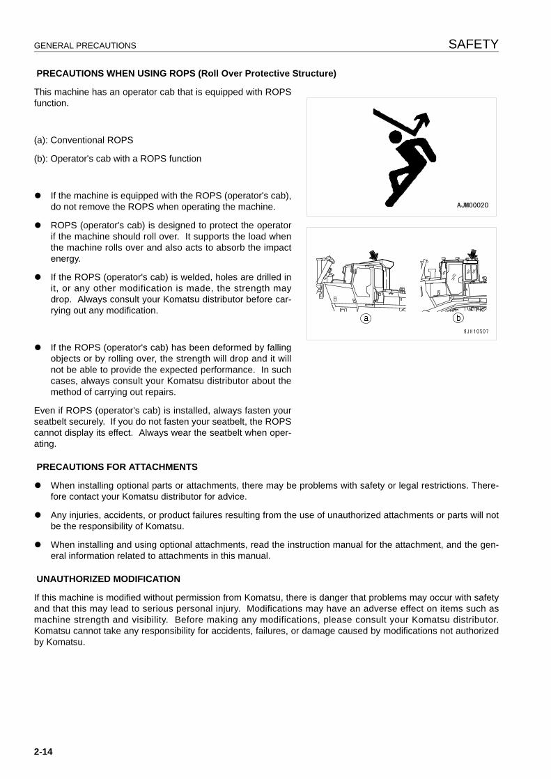
PRECAUTIONS WHEN USING ROPS (Roll Over Protective Structure)
This machine has an operator cab that is equipped with ROPSfunction.
(a): Conventional ROPS
(b): Operator's cab with a ROPS function
q If the machine is equipped with the ROPS (operator's cab),do not remove the ROPS when operating the machine.
q ROPS (operator's cab) is designed to protect the operatorif the machine should roll over. It supports the load whenthe machine rolls over and also acts to absorb the impactenergy.
q If the ROPS (operator's cab) is welded, holes are drilled init, or any other modification is made, the strength maydrop. Always consult your Komatsu distributor before car-rying out any modification.
q If the ROPS (operator's cab) has been deformed by fallingobjects or by rolling over, the strength will drop and it willnot be able to provide the expected performance. In suchcases, always consult your Komatsu distributor about themethod of carrying out repairs.
Even if ROPS (operator's cab) is installed, always fasten yourseatbelt securely. If you do not fasten your seatbelt, the ROPScannot display its effect. Always wear the seatbelt when oper-ating.
PRECAUTIONS FOR ATTACHMENTS
q When installing optional parts or attachments, there may be problems with safety or legal restrictions. There-fore contact your Komatsu distributor for advice.
q Any injuries, accidents, or product failures resulting from the use of unauthorized attachments or parts will notbe the responsibility of Komatsu.
q When installing and using optional attachments, read the instruction manual for the attachment, and the gen-eral information related to attachments in this manual.
UNAUTHORIZED MODIFICATION
If this machine is modified without permission from Komatsu, there is danger that problems may occur with safetyand that this may lead to serious personal injury. Modifications may have an adverse effect on items such asmachine strength and visibility. Before making any modifications, please consult your Komatsu distributor.Komatsu cannot take any responsibility for accidents, failures, or damage caused by modifications not authorizedby Komatsu.
2-14
SAFETY GENERAL PRECAUTIONS
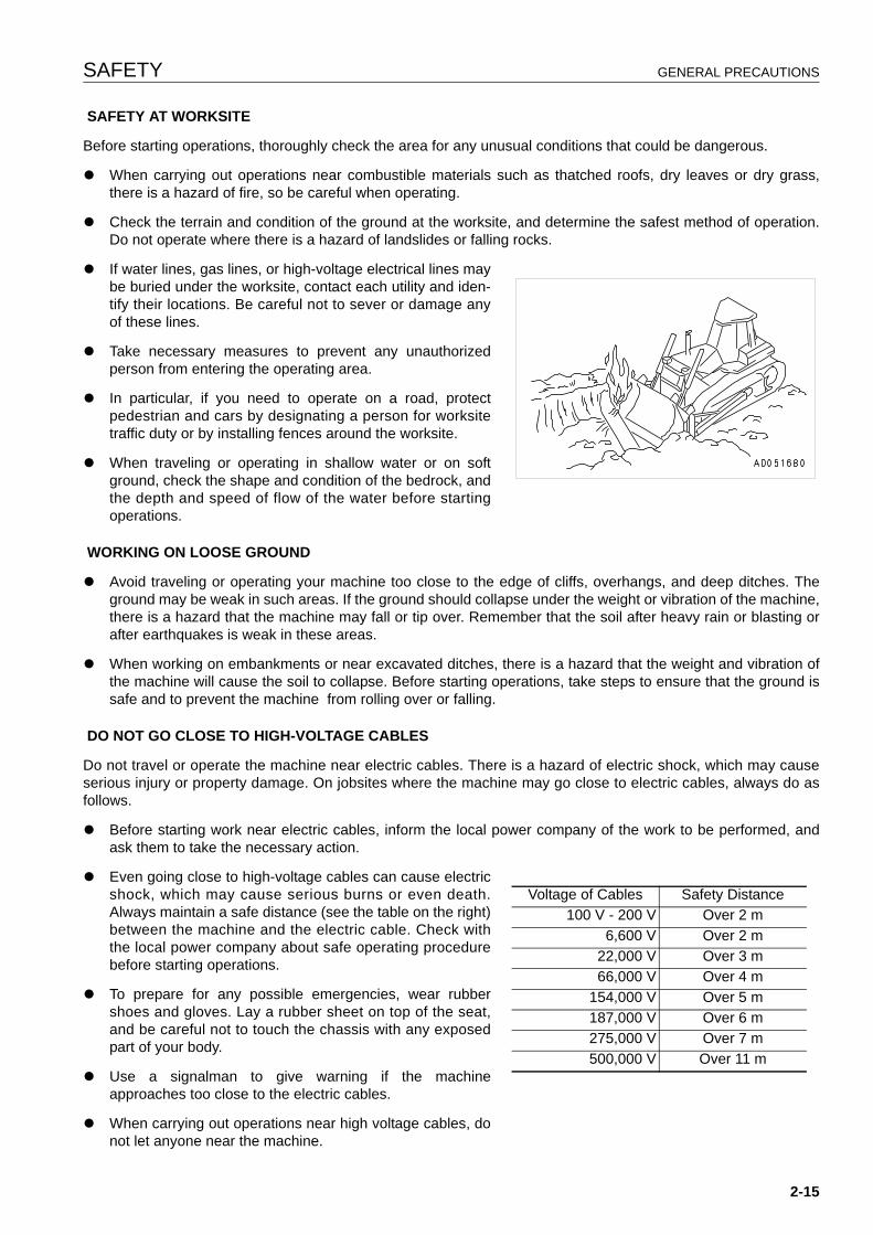
SAFETY AT WORKSITE
Before starting operations, thoroughly check the area for any unusual conditions that could be dangerous.
q When carrying out operations near combustible materials such as thatched roofs, dry leaves or dry grass,there is a hazard of fire, so be careful when operating.
q Check the terrain and condition of the ground at the worksite, and determine the safest method of operation.Do not operate where there is a hazard of landslides or falling rocks.
q If water lines, gas lines, or high-voltage electrical lines maybe buried under the worksite, contact each utility and iden-tify their locations. Be careful not to sever or damage anyof these lines.
q Take necessary measures to prevent any unauthorizedperson from entering the operating area.
q In particular, if you need to operate on a road, protectpedestrian and cars by designating a person for worksitetraffic duty or by installing fences around the worksite.
q When traveling or operating in shallow water or on softground, check the shape and condition of the bedrock, andthe depth and speed of flow of the water before startingoperations.
WORKING ON LOOSE GROUND
q Avoid traveling or operating your machine too close to the edge of cliffs, overhangs, and deep ditches. Theground may be weak in such areas. If the ground should collapse under the weight or vibration of the machine,there is a hazard that the machine may fall or tip over. Remember that the soil after heavy rain or blasting orafter earthquakes is weak in these areas.
q When working on embankments or near excavated ditches, there is a hazard that the weight and vibration ofthe machine will cause the soil to collapse. Before starting operations, take steps to ensure that the ground issafe and to prevent the machine from rolling over or falling.
DO NOT GO CLOSE TO HIGH-VOLTAGE CABLES
Do not travel or operate the machine near electric cables. There is a hazard of electric shock, which may causeserious injury or property damage. On jobsites where the machine may go close to electric cables, always do asfollows.
q Before starting work near electric cables, inform the local power company of the work to be performed, andask them to take the necessary action.
q Even going close to high-voltage cables can cause electricshock, which may cause serious burns or even death.Always maintain a safe distance (see the table on the right)between the machine and the electric cable. Check withthe local power company about safe operating procedurebefore starting operations.
q To prepare for any possible emergencies, wear rubbershoes and gloves. Lay a rubber sheet on top of the seat,and be careful not to touch the chassis with any exposedpart of your body.
q Use a signalman to give warning if the machineapproaches too close to the electric cables.
q When carrying out operations near high voltage cables, donot let anyone near the machine.
Voltage of Cables Safety Distance100 V - 200 V Over 2 m
6,600 V Over 2 m22,000 V Over 3 m66,000 V Over 4 m
154,000 V Over 5 m187,000 V Over 6 m275,000 V Over 7 m500,000 V Over 11 m
2-15
GENERAL PRECAUTIONS SAFETY
q If the machine should come too close or touch the electric cable, to prevent electric shock, the operator shouldnot leave the operator's compartment until it has been confirmed that the electricity has been shut off.
Also, do not let anyone near the machine.
ENSURE GOOD VISIBILITY
This machine is equipped with mirrors to improve the visibility, but even with mirrors, there are places, which can-not be seen from the operator's seat, so always be careful when operating.
When operating or traveling in places with poor visibility, if it is impossible to confirm the condition of the job side orobstacle is in the area around the machine, there is danger that the machine may suffer damage or the operatormay suffer serious personal injury. When operating or traveling in places with poor visibility, always observe thefollowing items strictly.
q If the visibility cannot be sufficiently assured, position a flagman if necessary. The operator should pay carefulattention to the signs and follow the instructions of the flagman.
q The signals should be given only by one flagman.
q When working in dark places, turn on the working lamps and front lamps of the machine, and if necessary, setup additional lighting in the area.
q Stop operations if there is poor visibility, such as in fog, snow, rain, or sand storms.
q Check the mirrors on the machine before starting operations every day. Clean off any dirt and adjust the viewto ensure good visibility.
VENTILATION FOR ENCLOSED AREAS
Exhaust fumes from the engine can kill.
q If it is necessary to start the engine within an enclosedarea, or when handling fuel, flushing oil, or paint, open thedoors and windows to ensure that adequate ventilation isprovided to prevent gas poisoning.
CHECKING SIGNALMAN'S SIGNALS AND SIGNS
q Set up signs to inform of road shoulders and soft ground. If the visibility is not good, position a signalman ifnecessary. Operators should pay careful attention to the signs and follow the instructions from the signalman.
q Only one signalman should give signals.
q Make sure that all workers understand the meaning of all signals and signs before starting work.
2-16
SAFETY GENERAL PRECAUTIONS
BE CAREFUL ABOUT ASBESTOS DUST
Asbestos dust in the air can cause lung cancer if it is inhaled.There is danger of inhaling asbestos when working on jobsiteshandling demolition work or work handling industrial waste.Always observe the following.
q Spray water to keep down the dust when cleaning. Do notuse compressed air for cleaning.
q If there is danger that there may be asbestos dust in theair, always operate the machine from an upwind position.All workers should use an approved respirator.
q Do not allow other persons to approach during the operation.
q Always observe the rules and regulations for the work site and environmental standards.
This machine does not use asbestos, but there is a danger that imitation parts may contain asbestos, so alwaysuse genuine Komatsu parts.
2-17
PRECAUTIONS FOR OPERATION SAFETY
PRECAUTIONS FOR OPERATION 2
BEFORE STARTING ENGINE 2
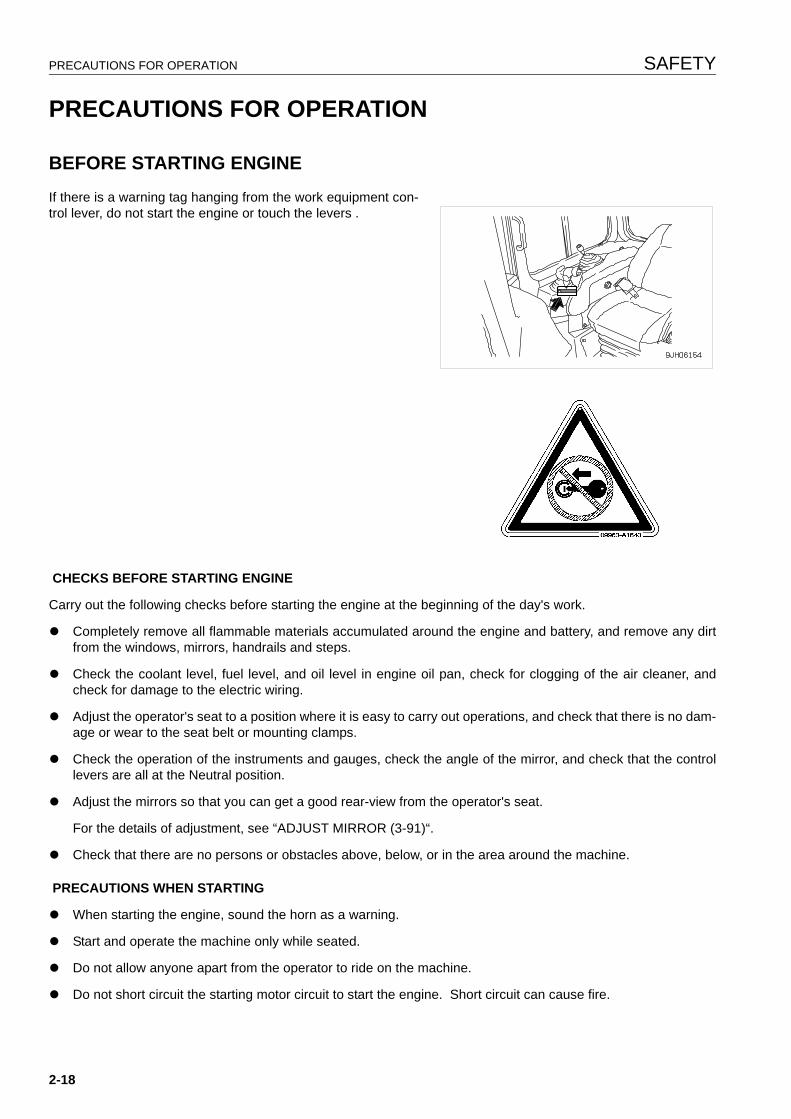
If there is a warning tag hanging from the work equipment con-trol lever, do not start the engine or touch the levers .
CHECKS BEFORE STARTING ENGINE
Carry out the following checks before starting the engine at the beginning of the day's work.
q Completely remove all flammable materials accumulated around the engine and battery, and remove any dirtfrom the windows, mirrors, handrails and steps.
q Check the coolant level, fuel level, and oil level in engine oil pan, check for clogging of the air cleaner, andcheck for damage to the electric wiring.
q Adjust the operator's seat to a position where it is easy to carry out operations, and check that there is no dam-age or wear to the seat belt or mounting clamps.
q Check the operation of the instruments and gauges, check the angle of the mirror, and check that the controllevers are all at the Neutral position.
q Adjust the mirrors so that you can get a good rear-view from the operator's seat.
For the details of adjustment, see “ADJUST MIRROR (3-91)“.
q Check that there are no persons or obstacles above, below, or in the area around the machine.
PRECAUTIONS WHEN STARTING
q When starting the engine, sound the horn as a warning.
q Start and operate the machine only while seated.
q Do not allow anyone apart from the operator to ride on the machine.
q Do not short circuit the starting motor circuit to start the engine. Short circuit can cause fire.
2-18
SAFETY PRECAUTIONS FOR OPERATION
PRECAUTIONS IN COLD AREAS
q Carry out the warming-up operation thoroughly. If the machine is not thoroughly warmed up before the controllevers are operated, the reaction of the machine will be slow, and this may lead to unexpected accidents.
q If the battery electrolyte is frozen, do not charge the battery or start the engine with a different power source.There is a hazard that this will ignite the battery and cause the battery to explode.
Before charging or starting the engine with a different power source, melt the battery electrolyte and check thatthere is no leakage of electrolyte before starting.
OPERATION 2
CHECKS BEFORE OPERATION
When carrying out the checks, move the machine to a wide area where there are no obstructions, and operateslowly. Do not allow anyone near the machine.
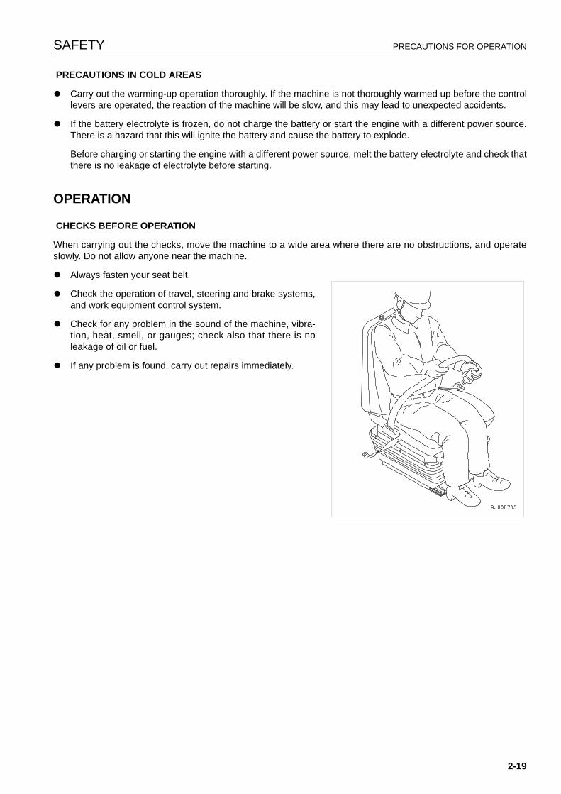
q Always fasten your seat belt.
q Check the operation of travel, steering and brake systems,and work equipment control system.
q Check for any problem in the sound of the machine, vibra-tion, heat, smell, or gauges; check also that there is noleakage of oil or fuel.
q If any problem is found, carry out repairs immediately.
2-19
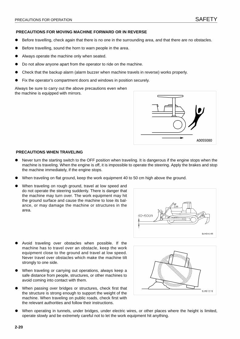
PRECAUTIONS FOR OPERATION SAFETY
PRECAUTIONS FOR MOVING MACHINE FORWARD OR IN REVERSE
q Before travelling, check again that there is no one in the surrounding area, and that there are no obstacles.
q Before travelling, sound the horn to warn people in the area.
q Always operate the machine only when seated.
q Do not allow anyone apart from the operator to ride on the machine.
q Check that the backup alarm (alarm buzzer when machine travels in reverse) works properly.
q Fix the operator's compartment doors and windows in position securely.
Always be sure to carry out the above precautions even whenthe machine is equipped with mirrors.
PRECAUTIONS WHEN TRAVELING
q Never turn the starting switch to the OFF position when traveling. It is dangerous if the engine stops when themachine is traveling. When the engine is off, it is impossible to operate the steering. Apply the brakes and stopthe machine immediately, if the engine stops.
q When traveling on flat ground, keep the work equipment 40 to 50 cm high above the ground.
q When traveling on rough ground, travel at low speed anddo not operate the steering suddenly. There is danger thatthe machine may turn over. The work equipment may hitthe ground surface and cause the machine to lose its bal-ance, or may damage the machine or structures in thearea.
q Avoid traveling over obstacles when possible. If themachine has to travel over an obstacle, keep the workequipment close to the ground and travel at low speed.Never travel over obstacles which make the machine tiltstrongly to one side.
q When traveling or carrying out operations, always keep asafe distance from people, structures, or other machines toavoid coming into contact with them.
q When passing over bridges or structures, check first thatthe structure is strong enough to support the weight of themachine. When traveling on public roads, check first withthe relevant authorities and follow their instructions.
q When operating in tunnels, under bridges, under electric wires, or other places where the height is limited,operate slowly and be extremely careful not to let the work equipment hit anything.
2-20
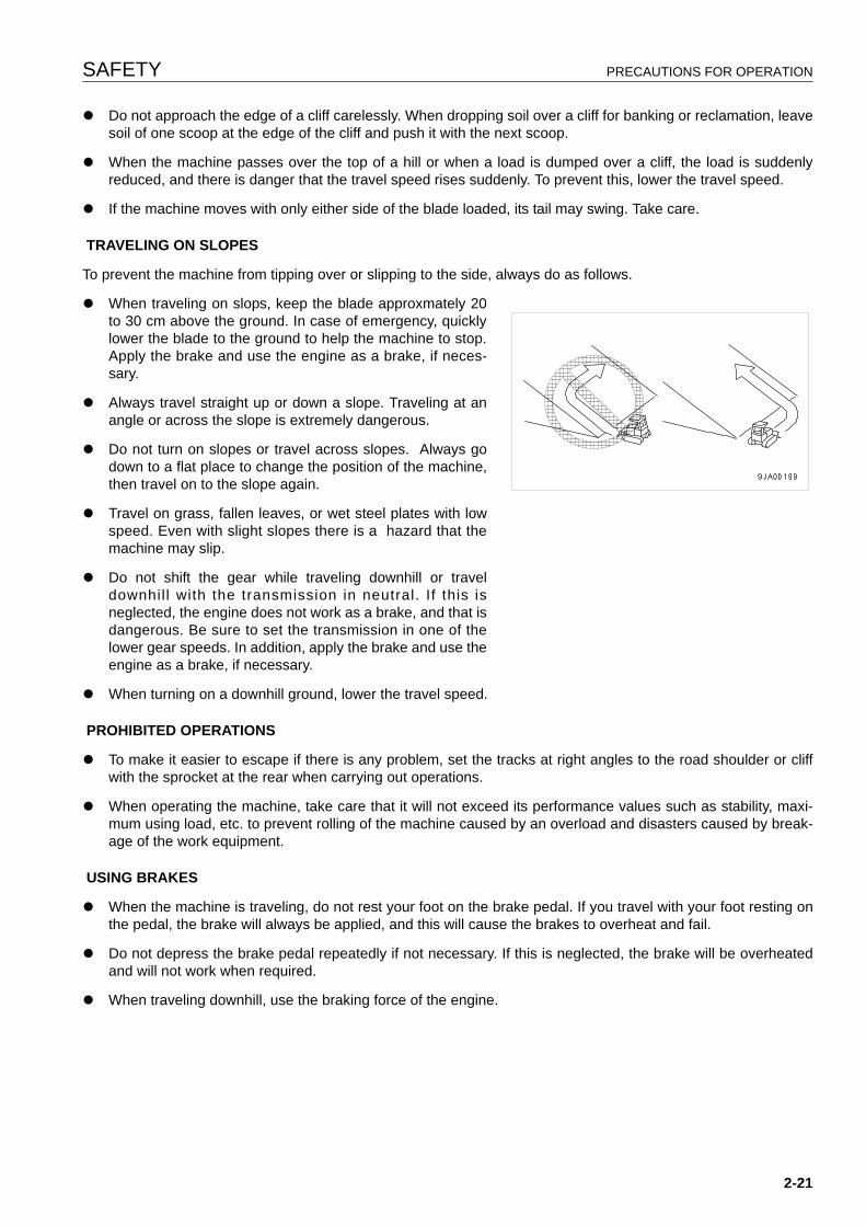
SAFETY PRECAUTIONS FOR OPERATION
q Do not approach the edge of a cliff carelessly. When dropping soil over a cliff for banking or reclamation, leavesoil of one scoop at the edge of the cliff and push it with the next scoop.
q When the machine passes over the top of a hill or when a load is dumped over a cliff, the load is suddenlyreduced, and there is danger that the travel speed rises suddenly. To prevent this, lower the travel speed.
q If the machine moves with only either side of the blade loaded, its tail may swing. Take care.
TRAVELING ON SLOPES
To prevent the machine from tipping over or slipping to the side, always do as follows.
q When traveling on slops, keep the blade approxmately 20to 30 cm above the ground. In case of emergency, quicklylower the blade to the ground to help the machine to stop.Apply the brake and use the engine as a brake, if neces-sary.
q Always travel straight up or down a slope. Traveling at anangle or across the slope is extremely dangerous.
q Do not turn on slopes or travel across slopes. Always godown to a flat place to change the position of the machine,then travel on to the slope again.
q Travel on grass, fallen leaves, or wet steel plates with lowspeed. Even with slight slopes there is a hazard that themachine may slip.
q Do not shift the gear while traveling downhill or traveldownhil l with the transmission in neutral. If this isneglected, the engine does not work as a brake, and that isdangerous. Be sure to set the transmission in one of thelower gear speeds. In addition, apply the brake and use theengine as a brake, if necessary.
q When turning on a downhill ground, lower the travel speed.
PROHIBITED OPERATIONS
q To make it easier to escape if there is any problem, set the tracks at right angles to the road shoulder or cliffwith the sprocket at the rear when carrying out operations.
q When operating the machine, take care that it will not exceed its performance values such as stability, maxi-mum using load, etc. to prevent rolling of the machine caused by an overload and disasters caused by break-age of the work equipment.
USING BRAKES
q When the machine is traveling, do not rest your foot on the brake pedal. If you travel with your foot resting onthe pedal, the brake will always be applied, and this will cause the brakes to overheat and fail.
q Do not depress the brake pedal repeatedly if not necessary. If this is neglected, the brake will be overheatedand will not work when required.
q When traveling downhill, use the braking force of the engine.
2-21
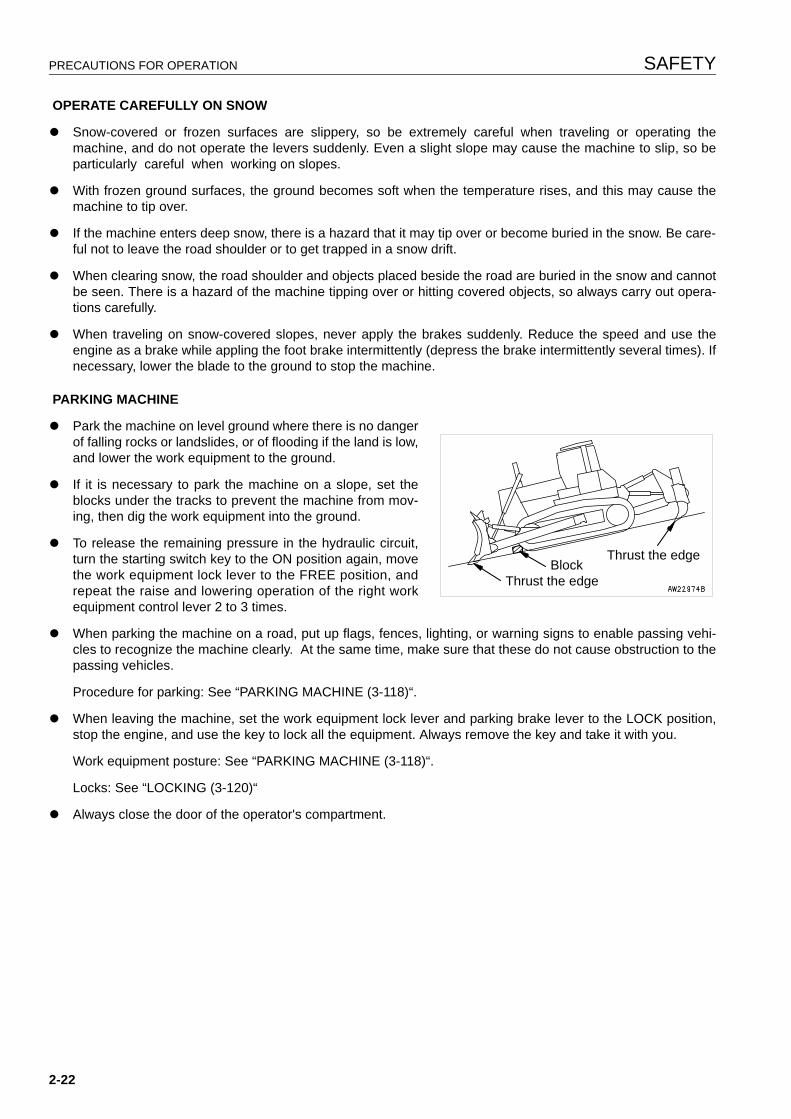
PRECAUTIONS FOR OPERATION SAFETY
OPERATE CAREFULLY ON SNOW
q Snow-covered or frozen surfaces are slippery, so be extremely careful when traveling or operating themachine, and do not operate the levers suddenly. Even a slight slope may cause the machine to slip, so beparticularly careful when working on slopes.
q With frozen ground surfaces, the ground becomes soft when the temperature rises, and this may cause themachine to tip over.
q If the machine enters deep snow, there is a hazard that it may tip over or become buried in the snow. Be care-ful not to leave the road shoulder or to get trapped in a snow drift.
q When clearing snow, the road shoulder and objects placed beside the road are buried in the snow and cannotbe seen. There is a hazard of the machine tipping over or hitting covered objects, so always carry out opera-tions carefully.
q When traveling on snow-covered slopes, never apply the brakes suddenly. Reduce the speed and use theengine as a brake while appling the foot brake intermittently (depress the brake intermittently several times). Ifnecessary, lower the blade to the ground to stop the machine.
PARKING MACHINE
q Park the machine on level ground where there is no dangerof falling rocks or landslides, or of flooding if the land is low,and lower the work equipment to the ground.
q If it is necessary to park the machine on a slope, set theblocks under the tracks to prevent the machine from mov-ing, then dig the work equipment into the ground.
q To release the remaining pressure in the hydraulic circuit,turn the starting switch key to the ON position again, movethe work equipment lock lever to the FREE position, andrepeat the raise and lowering operation of the right workequipment control lever 2 to 3 times.
q When parking the machine on a road, put up flags, fences, lighting, or warning signs to enable passing vehi-cles to recognize the machine clearly. At the same time, make sure that these do not cause obstruction to thepassing vehicles.
Procedure for parking: See “PARKING MACHINE (3-118)“.
q When leaving the machine, set the work equipment lock lever and parking brake lever to the LOCK position,stop the engine, and use the key to lock all the equipment. Always remove the key and take it with you.
Work equipment posture: See “PARKING MACHINE (3-118)“.
Locks: See “LOCKING (3-120)“
q Always close the door of the operator's compartment.
Thrust the edgeBlock
Thrust the edge
2-22
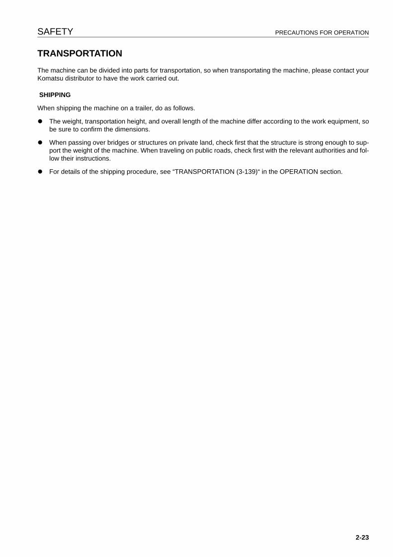
SAFETY PRECAUTIONS FOR OPERATION
TRANSPORTATION 2
The machine can be divided into parts for transportation, so when transportating the machine, please contact yourKomatsu distributor to have the work carried out.
SHIPPING
When shipping the machine on a trailer, do as follows.
q The weight, transportation height, and overall length of the machine differ according to the work equipment, sobe sure to confirm the dimensions.
q When passing over bridges or structures on private land, check first that the structure is strong enough to sup-port the weight of the machine. When traveling on public roads, check first with the relevant authorities and fol-low their instructions.
q For details of the shipping procedure, see “TRANSPORTATION (3-139)“ in the OPERATION section.
2-23
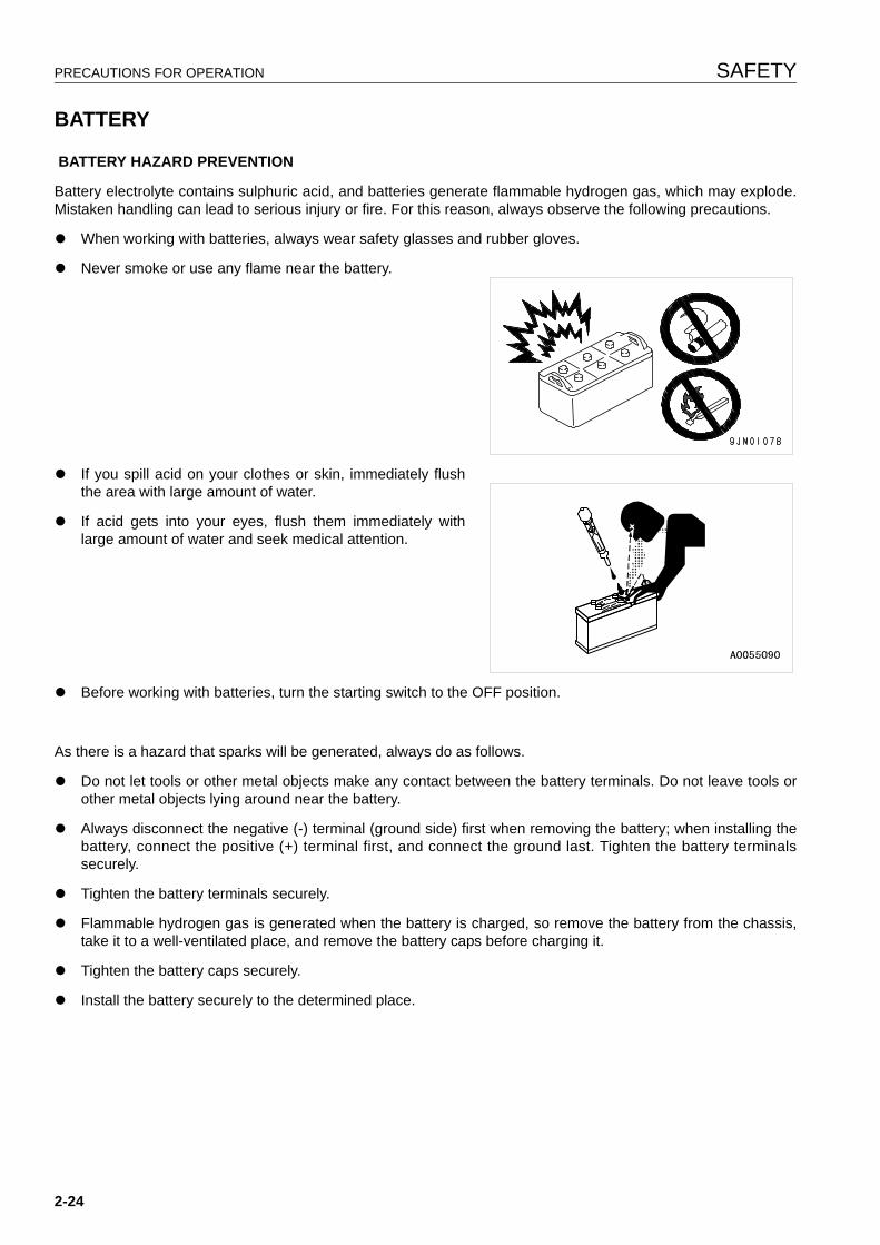
PRECAUTIONS FOR OPERATION SAFETY
BATTERY 2
BATTERY HAZARD PREVENTION
Battery electrolyte contains sulphuric acid, and batteries generate flammable hydrogen gas, which may explode.Mistaken handling can lead to serious injury or fire. For this reason, always observe the following precautions.
q When working with batteries, always wear safety glasses and rubber gloves.
q Never smoke or use any flame near the battery.
q If you spill acid on your clothes or skin, immediately flushthe area with large amount of water.
q If acid gets into your eyes, flush them immediately withlarge amount of water and seek medical attention.
q Before working with batteries, turn the starting switch to the OFF position.
As there is a hazard that sparks will be generated, always do as follows.
q Do not let tools or other metal objects make any contact between the battery terminals. Do not leave tools orother metal objects lying around near the battery.
q Always disconnect the negative (-) terminal (ground side) first when removing the battery; when installing thebattery, connect the positive (+) terminal first, and connect the ground last. Tighten the battery terminalssecurely.
q Tighten the battery terminals securely.
q Flammable hydrogen gas is generated when the battery is charged, so remove the battery from the chassis,take it to a well-ventilated place, and remove the battery caps before charging it.
q Tighten the battery caps securely.
q Install the battery securely to the determined place.
2-24
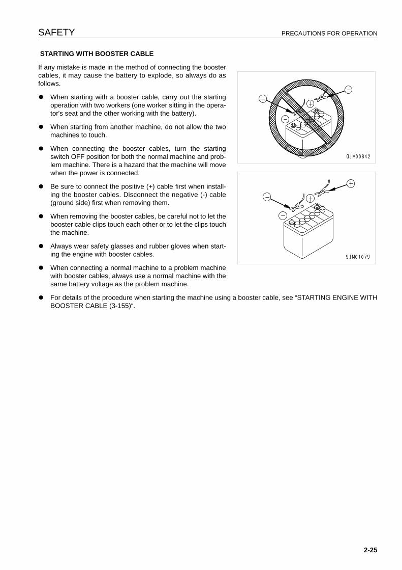
SAFETY PRECAUTIONS FOR OPERATION
STARTING WITH BOOSTER CABLE
If any mistake is made in the method of connecting the boostercables, it may cause the battery to explode, so always do asfollows.
q When starting with a booster cable, carry out the startingoperation with two workers (one worker sitting in the opera-tor's seat and the other working with the battery).
q When starting from another machine, do not allow the twomachines to touch.
q When connecting the booster cables, turn the startingswitch OFF position for both the normal machine and prob-lem machine. There is a hazard that the machine will movewhen the power is connected.
q Be sure to connect the positive (+) cable first when install-ing the booster cables. Disconnect the negative (-) cable(ground side) first when removing them.
q When removing the booster cables, be careful not to let thebooster cable clips touch each other or to let the clips touchthe machine.
q Always wear safety glasses and rubber gloves when start-ing the engine with booster cables.
q When connecting a normal machine to a problem machinewith booster cables, always use a normal machine with thesame battery voltage as the problem machine.
q For details of the procedure when starting the machine using a booster cable, see “STARTING ENGINE WITHBOOSTER CABLE (3-155)“.
2-25
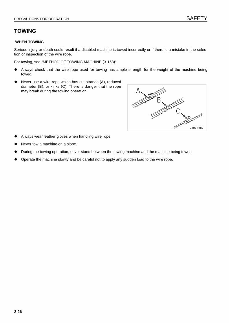
PRECAUTIONS FOR OPERATION SAFETY
TOWING 2
WHEN TOWING
Serious injury or death could result if a disabled machine is towed incorrectly or if there is a mistake in the selec-tion or inspection of the wire rope.
For towing, see “METHOD OF TOWING MACHINE (3-153)“.
q Always check that the wire rope used for towing has ample strength for the weight of the machine beingtowed.
q Never use a wire rope which has cut strands (A), reduceddiameter (B), or kinks (C). There is danger that the ropemay break during the towing operation.
q Always wear leather gloves when handling wire rope.
q Never tow a machine on a slope.
q During the towing operation, never stand between the towing machine and the machine being towed.
q Operate the machine slowly and be careful not to apply any sudden load to the wire rope.
2-26
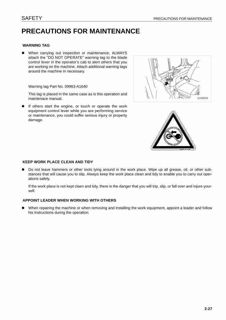
SAFETY PRECAUTIONS FOR MAINTENANCE
PRECAUTIONS FOR MAINTENANCE 2
WARNING TAG
q When carrying out inspection or maintenance, ALWAYSattach the “DO NOT OPERATE“ warning tag to the bladecontrol lever in the operator's cab to alert others that youare working on the machine. Attach additional warning tagsaround the machine in necessary.
Warning tag Part No. 09963-A1640
This tag is placed in the same case as is this operation andmaintenace manual.
q If others start the engine, or touch or operate the workequipment control lever while you are performing serviceor maintenance, you could suffer serious injury or propertydamage.
KEEP WORK PLACE CLEAN AND TIDY
q Do not leave hammers or other tools lying around in the work place. Wipe up all grease, oil, or other sub-stances that will cause you to slip. Always keep the work place clean and tidy to enable you to carry out oper-ations safely.
If the work place is not kept claen and tidy, there is the danger that you will trip, slip, or fall over and injure your-self.
APPOINT LEADER WHEN WORKING WITH OTHERS
q When repairing the machine or when removing and installing the work equipment, appoint a leader and followhis instructions during the operation.
2-27
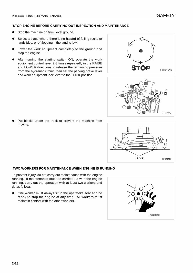
PRECAUTIONS FOR MAINTENANCE SAFETY
STOP ENGINE BEFORE CARRYING OUT INSPECTION AND MAINTENANCE
q Stop the machine on firm, level ground.
q Select a place where there is no hazard of falling rocks orlandslides, or of flooding if the land is low.
q Lower the work equipment completely to the ground andstop the engine.
q After turning the starting switch ON, operate the workequipment control lever 2-3 times repeatedly in the RAISEand LOWER directions to release the remaining pressurefrom the hydraulic circuit, then set the parking brake leverand work equipment lock lever to the LOCK position.
q Put blocks under the track to prevent the machine frommoving.
TWO WORKERS FOR MAINTENANCE WHEN ENGINE IS RUNNING
To prevent injury, do not carry out maintenance with the enginerunning. If maintenance must be carried out with the enginerunning, carry out the operation with at least two workers anddo as follows.
q One worker must always sit in the operator's seat and beready to stop the engine at any time. All workers mustmaintain contact with the other workers.
Block
2-28
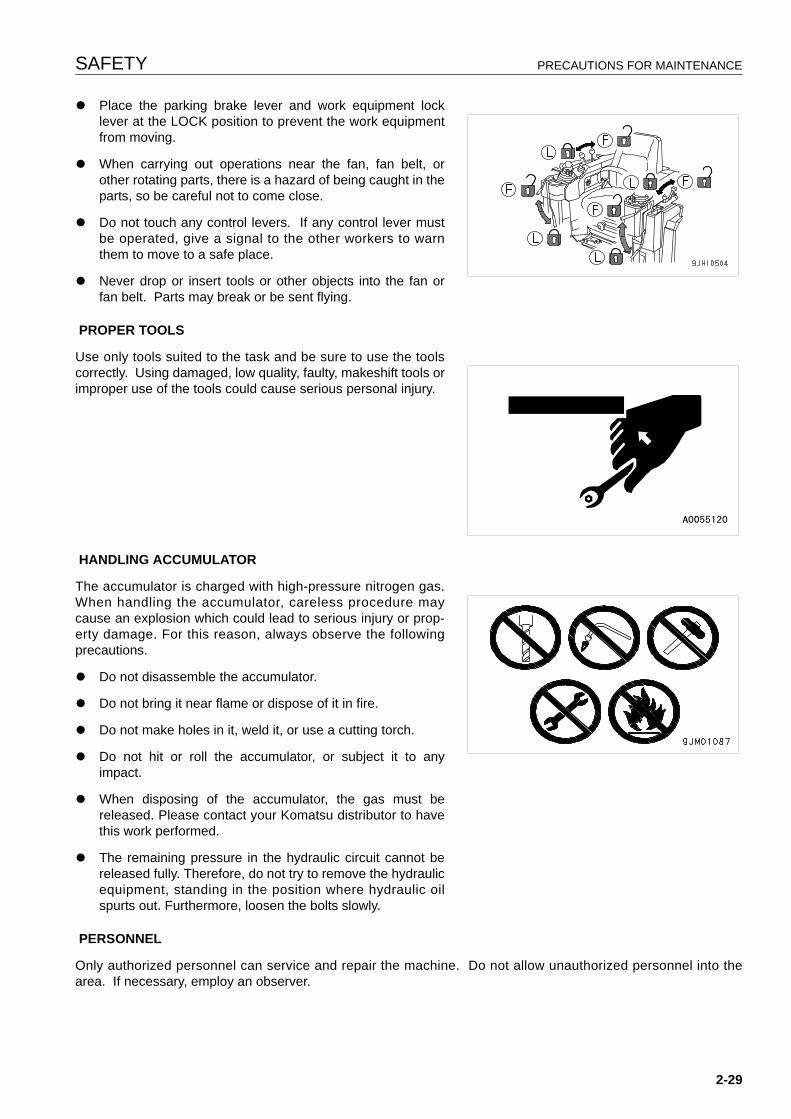
SAFETY PRECAUTIONS FOR MAINTENANCE
q Place the parking brake lever and work equipment locklever at the LOCK position to prevent the work equipmentfrom moving.
q When carrying out operations near the fan, fan belt, orother rotating parts, there is a hazard of being caught in theparts, so be careful not to come close.
q Do not touch any control levers. If any control lever mustbe operated, give a signal to the other workers to warnthem to move to a safe place.
q Never drop or insert tools or other objects into the fan orfan belt. Parts may break or be sent flying.
PROPER TOOLS
Use only tools suited to the task and be sure to use the toolscorrectly. Using damaged, low quality, faulty, makeshift tools orimproper use of the tools could cause serious personal injury.
HANDLING ACCUMULATOR
The accumulator is charged with high-pressure nitrogen gas.When handling the accumulator, careless procedure maycause an explosion which could lead to serious injury or prop-erty damage. For this reason, always observe the followingprecautions.
q Do not disassemble the accumulator.
q Do not bring it near flame or dispose of it in fire.
q Do not make holes in it, weld it, or use a cutting torch.
q Do not hit or roll the accumulator, or subject it to anyimpact.
q When disposing of the accumulator, the gas must bereleased. Please contact your Komatsu distributor to havethis work performed.
q The remaining pressure in the hydraulic circuit cannot bereleased fully. Therefore, do not try to remove the hydraulicequipment, standing in the position where hydraulic oilspurts out. Furthermore, loosen the bolts slowly.
PERSONNEL
Only authorized personnel can service and repair the machine. Do not allow unauthorized personnel into thearea. If necessary, employ an observer.
2-29
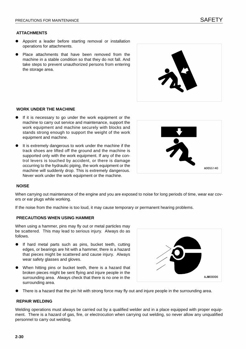
PRECAUTIONS FOR MAINTENANCE SAFETY
ATTACHMENTS
q Appoint a leader before starting removal or installationoperations for attachments.
q Place attachments that have been removed from themachine in a stable condition so that they do not fall. Andtake steps to prevent unauthorized persons from enteringthe storage area.
WORK UNDER THE MACHINE
q If it is necessary to go under the work equipment or themachine to carry out service and maintenance, support thework equipment and machine securely with blocks andstands strong enough to support the weight of the workequipment and machine.
q It is extremely dangerous to work under the machine if thetrack shoes are lifted off the ground and the machine issupported only with the work equipment. If any of the con-trol levers is touched by accident, or there is damageoccurring to the hydraulic piping, the work equipment or themachine will suddenly drop. This is extremely dangerous.Never work under the work equipment or the machine.
NOISE
When carrying out maintenance of the engine and you are exposed to noise for long periods of time, wear ear cov-ers or ear plugs while working.
If the noise from the machine is too loud, it may cause temporary or permanent hearing problems.
PRECAUTIONS WHEN USING HAMMER
When using a hammer, pins may fly out or metal particles maybe scattered. This may lead to serious injury. Always do asfollows.
q If hard metal parts such as pins, bucket teeth, cuttingedges, or bearings are hit with a hammer, there is a hazardthat pieces might be scattered and cause injury. Alwayswear safety glasses and gloves.
q When hitting pins or bucket teeth, there is a hazard thatbroken pieces might be sent flying and injure people in thesurrounding area. Always check that there is no one in thesurrounding area.
q There is a hazard that the pin hit with strong force may fly out and injure people in the surrounding area.
REPAIR WELDING
Welding operations must always be carried out by a qualified welder and in a place equipped with proper equip-ment. There is a hazard of gas, fire, or electrocution when carrying out welding, so never allow any unqualifiedpersonnel to carry out welding.
2-30
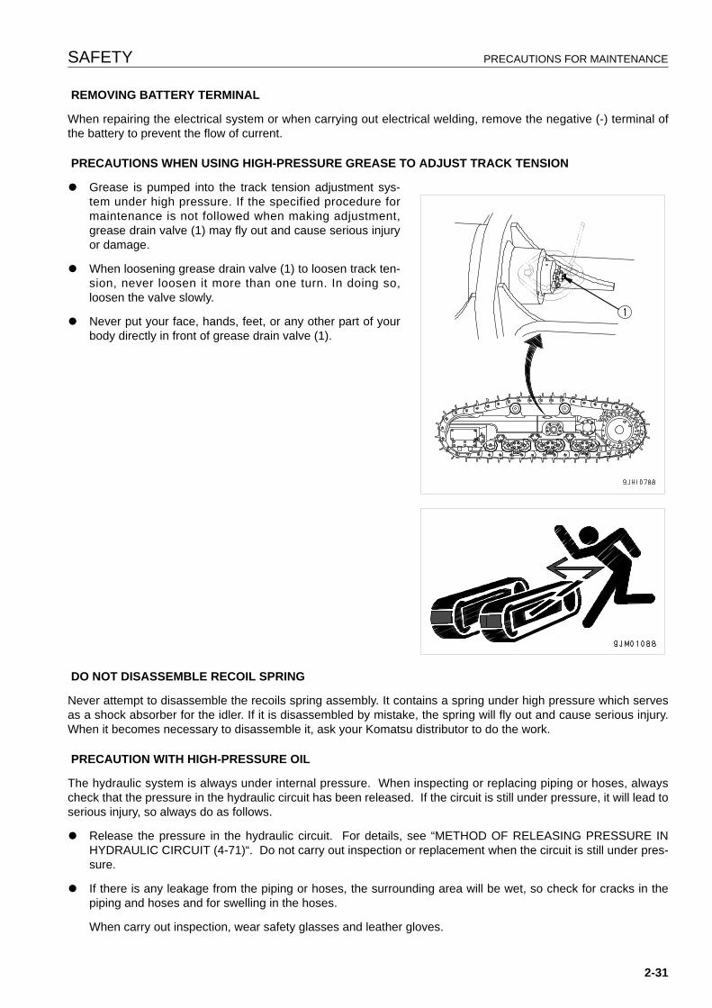
SAFETY PRECAUTIONS FOR MAINTENANCE
REMOVING BATTERY TERMINAL
When repairing the electrical system or when carrying out electrical welding, remove the negative (-) terminal ofthe battery to prevent the flow of current.
PRECAUTIONS WHEN USING HIGH-PRESSURE GREASE TO ADJUST TRACK TENSION
q Grease is pumped into the track tension adjustment sys-tem under high pressure. If the specified procedure formaintenance is not followed when making adjustment,grease drain valve (1) may fly out and cause serious injuryor damage.
q When loosening grease drain valve (1) to loosen track ten-sion, never loosen it more than one turn. In doing so,loosen the valve slowly.
q Never put your face, hands, feet, or any other part of yourbody directly in front of grease drain valve (1).
DO NOT DISASSEMBLE RECOIL SPRING
Never attempt to disassemble the recoils spring assembly. It contains a spring under high pressure which servesas a shock absorber for the idler. If it is disassembled by mistake, the spring will fly out and cause serious injury.When it becomes necessary to disassemble it, ask your Komatsu distributor to do the work.
PRECAUTION WITH HIGH-PRESSURE OIL
The hydraulic system is always under internal pressure. When inspecting or replacing piping or hoses, alwayscheck that the pressure in the hydraulic circuit has been released. If the circuit is still under pressure, it will lead toserious injury, so always do as follows.
q Release the pressure in the hydraulic circuit. For details, see “METHOD OF RELEASING PRESSURE INHYDRAULIC CIRCUIT (4-71)“. Do not carry out inspection or replacement when the circuit is still under pres-sure.
q If there is any leakage from the piping or hoses, the surrounding area will be wet, so check for cracks in thepiping and hoses and for swelling in the hoses.
When carry out inspection, wear safety glasses and leather gloves.
2-31
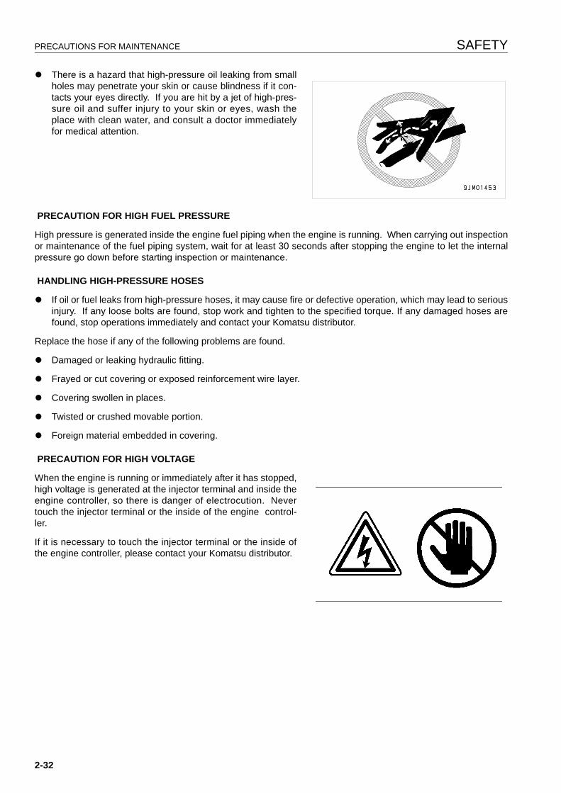
PRECAUTIONS FOR MAINTENANCE SAFETY
q There is a hazard that high-pressure oil leaking from smallholes may penetrate your skin or cause blindness if it con-tacts your eyes directly. If you are hit by a jet of high-pres-sure oil and suffer injury to your skin or eyes, wash theplace with clean water, and consult a doctor immediatelyfor medical attention.
PRECAUTION FOR HIGH FUEL PRESSURE
High pressure is generated inside the engine fuel piping when the engine is running. When carrying out inspectionor maintenance of the fuel piping system, wait for at least 30 seconds after stopping the engine to let the internalpressure go down before starting inspection or maintenance.
HANDLING HIGH-PRESSURE HOSES
q If oil or fuel leaks from high-pressure hoses, it may cause fire or defective operation, which may lead to seriousinjury. If any loose bolts are found, stop work and tighten to the specified torque. If any damaged hoses arefound, stop operations immediately and contact your Komatsu distributor.
Replace the hose if any of the following problems are found.
q Damaged or leaking hydraulic fitting.
q Frayed or cut covering or exposed reinforcement wire layer.
q Covering swollen in places.
q Twisted or crushed movable portion.
q Foreign material embedded in covering.
PRECAUTION FOR HIGH VOLTAGE
When the engine is running or immediately after it has stopped,high voltage is generated at the injector terminal and inside theengine controller, so there is danger of electrocution. Nevertouch the injector terminal or the inside of the engine control-ler.
If it is necessary to touch the injector terminal or the inside ofthe engine controller, please contact your Komatsu distributor.
2-32
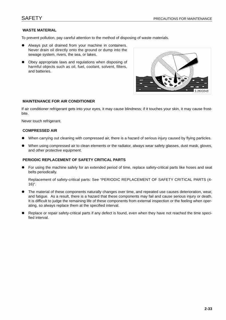
SAFETY PRECAUTIONS FOR MAINTENANCE
WASTE MATERIAL
To prevent pollution, pay careful attention to the method of disposing of waste materials.
q Always put oil drained from your machine in containers.Never drain oil directly onto the ground or dump into thesewage system, rivers, the sea, or lakes.
q Obey appropriate laws and regulations when disposing ofharmful objects such as oil, fuel, coolant, solvent, filters,and batteries.
MAINTENANCE FOR AIR CONDITIONER
If air conditioner refrigerant gets into your eyes, it may cause blindness; if it touches your skin, it may cause frost-bite.
Never touch refrigerant.
COMPRESSED AIR
q When carrying out cleaning with compressed air, there is a hazard of serious injury caused by flying particles.
q When using compressed air to clean elements or the radiator, always wear safety glasses, dust mask, gloves,and other protective equipment.
PERIODIC REPLACEMENT OF SAFETY CRITICAL PARTS
q For using the machine safely for an extended period of time, replace safety-critical parts like hoses and seatbelts periodically.
Replacement of safety-critical parts: See “PERIODIC REPLACEMENT OF SAFETY CRITICAL PARTS (4-16)“.
q The material of these components naturally changes over time, and repeated use causes deterioration, wear,and fatigue. As a result, there is a hazard that these components may fail and cause serious injury or death.It is difficult to judge the remaining life of these components from external inspection or the feeling when oper-ating, so always replace them at the specified interval.
q Replace or repair safety-critical parts if any defect is found, even when they have not reached the time speci-fied interval.
2-33

PRECAUTIONS FOR MAINTENANCE SAFETY
2-34

OPERATION
13
WARNINGPlease read and make sure that you understand the SAFETYsection before reading this section.
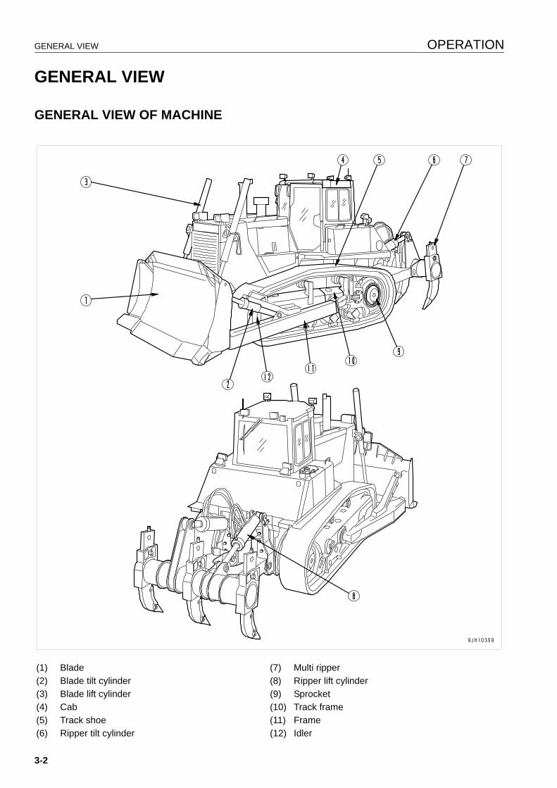
GENERAL VIEW OPERATION
GENERAL VIEW 3
GENERAL VIEW OF MACHINE 3
(1) Blade (7) Multi ripper(2) Blade tilt cylinder (8) Ripper lift cylinder(3) Blade lift cylinder (9) Sprocket(4) Cab (10) Track frame(5) Track shoe (11) Frame(6) Ripper tilt cylinder (12) Idler
3-2
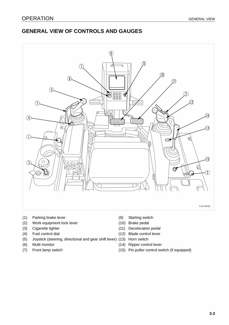
OPERATION GENERAL VIEW
GENERAL VIEW OF CONTROLS AND GAUGES 3
(1) Parking brake lever (9) Starting switch(2) Work equipment lock lever (10) Brake pedal(3) Cigarette lighter (11) Deceleration pedal(4) Fuel control dial (12) Blade control lever(5) Joystick (steering, directional and gear shift lever) (13) Horn switch(6) Multi monitor (14) Ripper control lever(7) Front lamp switch (15) Pin puller control switch (if equipped)
3-3
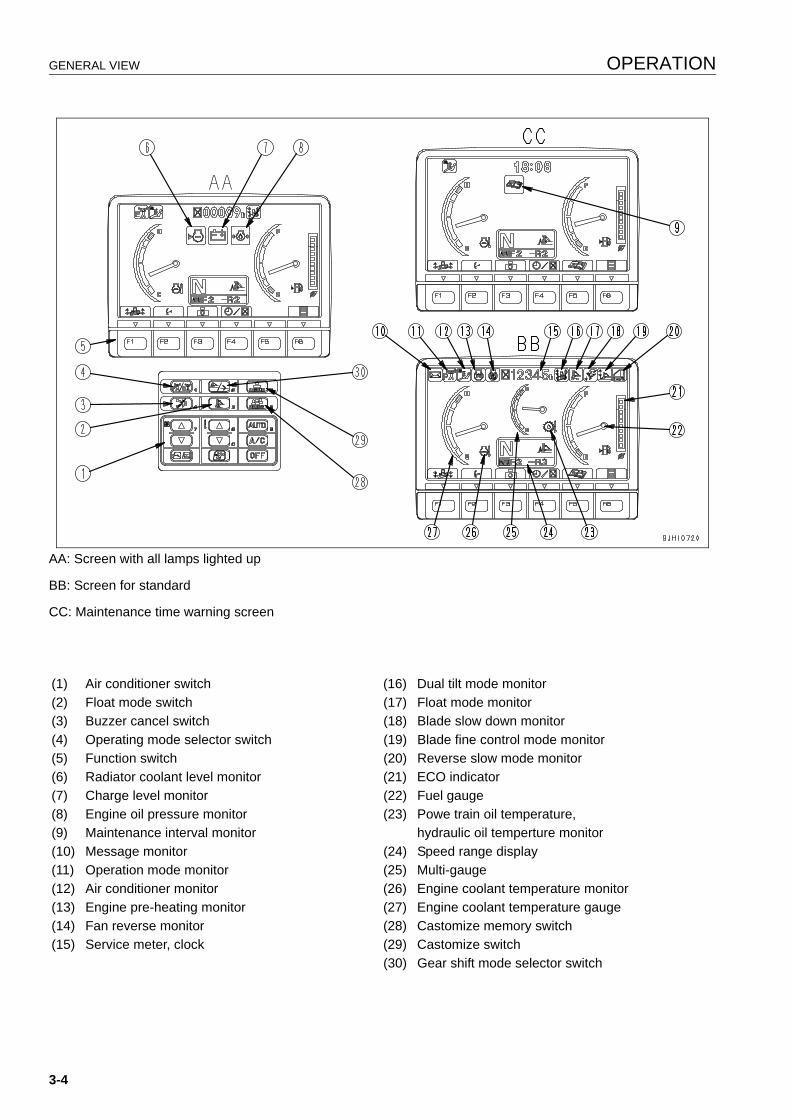
GENERAL VIEW OPERATION
AA: Screen with all lamps lighted up
BB: Screen for standard
CC: Maintenance time warning screen
(1) Air conditioner switch (16) Dual tilt mode monitor(2) Float mode switch (17) Float mode monitor(3) Buzzer cancel switch (18) Blade slow down monitor(4) Operating mode selector switch (19) Blade fine control mode monitor(5) Function switch (20) Reverse slow mode monitor(6) Radiator coolant level monitor (21) ECO indicator(7) Charge level monitor (22) Fuel gauge(8) Engine oil pressure monitor (23) Powe train oil temperature, (9) Maintenance interval monitor hydraulic oil temperture monitor(10) Message monitor (24) Speed range display(11) Operation mode monitor (25) Multi-gauge(12) Air conditioner monitor (26) Engine coolant temperature monitor(13) Engine pre-heating monitor (27) Engine coolant temperature gauge(14) Fan reverse monitor (28) Castomize memory switch(15) Service meter, clock (29) Castomize switch
(30) Gear shift mode selector switch
3-4
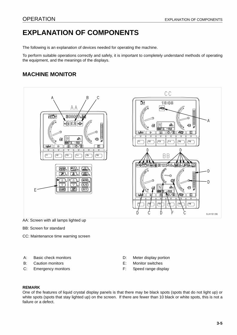
OPERATION EXPLANATION OF COMPONENTS
EXPLANATION OF COMPONENTS 3
The following is an explanation of devices needed for operating the machine.
To perform suitable operations correctly and safely, it is important to completely understand methods of operatingthe equipment, and the meanings of the displays.
MACHINE MONITOR 3
AA: Screen with all lamps lighted up
BB: Screen for standard
CC: Maintenance time warning screen
REMARKOne of the features of liquid crystal display panels is that there may be black spots (spots that do not light up) orwhite spots (spots that stay lighted up) on the screen. If there are fewer than 10 black or white spots, this is not afailure or a defect.
A: Basic check monitors D: Meter display portionB: Caution monitors E: Monitor switchesC: Emergency monitors F: Speed range display
3-5

EXPLANATION OF COMPONENTS OPERATION
BASIC OPERATION OF MACHINE MONITOR 3
STARTING ENGINE WHEN SITUATION IS NORMAL
q When the starting switch is turned to the ON position, the opening screen GG is displayed.
q After the opening screen GG is displayed for 2 seconds, the screen switches to the check before startingscreen DD.
q After the check before starting screen DD is displayed for 2 seconds, the screen switches to the mode displayscreen.
q After the mode display screen HH is displayed for 2 seconds, the screen switches to standard display screenBB.
REMARKWhen the engine is started, the battery voltage may suddenly drop depending on the temperature and the batterycondition. If this happens, the display on the machine monitor may momentarily go out, but this does not indicateany abnormality.
3-6
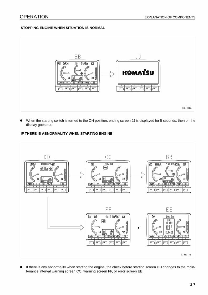
OPERATION EXPLANATION OF COMPONENTS
STOPPING ENGINE WHEN SITUATION IS NORMAL
q When the starting switch is turned to the ON position, ending screen JJ is displayed for 5 seconds, then on thedisplay goes out.
IF THERE IS ABNORMALITY WHEN STARTING ENGINE
q If there is any abnormality when starting the engine, the check before starting screen DD changes to the main-tenance interval warning screen CC, warning screen FF, or error screen EE.
3-7
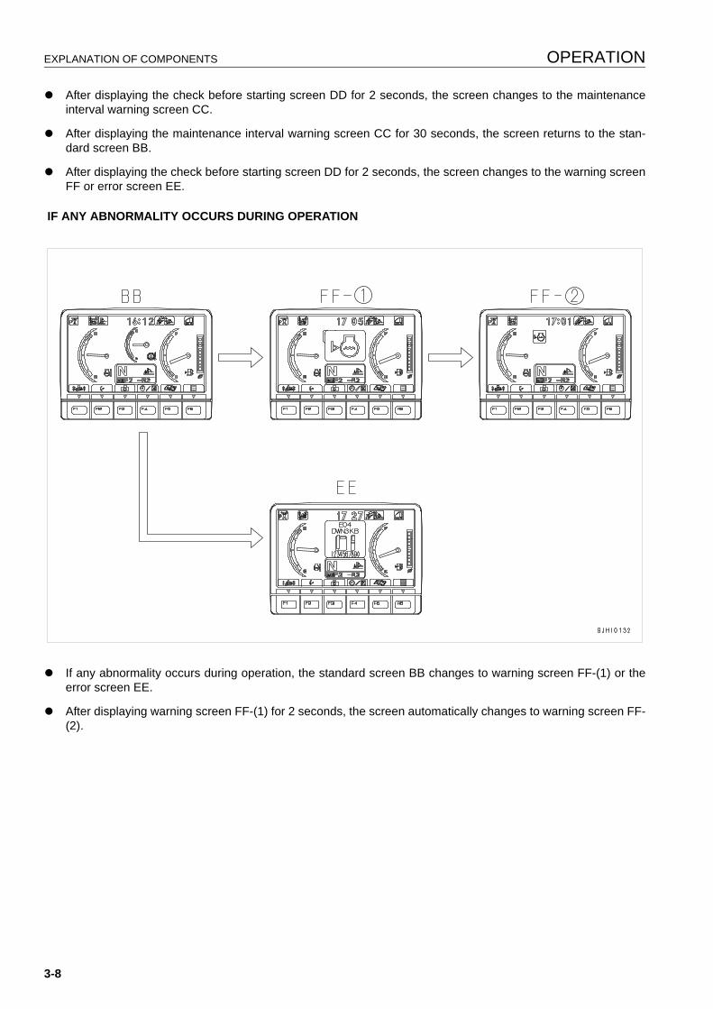
EXPLANATION OF COMPONENTS OPERATION
q After displaying the check before starting screen DD for 2 seconds, the screen changes to the maintenanceinterval warning screen CC.
q After displaying the maintenance interval warning screen CC for 30 seconds, the screen returns to the stan-dard screen BB.
q After displaying the check before starting screen DD for 2 seconds, the screen changes to the warning screenFF or error screen EE.
IF ANY ABNORMALITY OCCURS DURING OPERATION
q If any abnormality occurs during operation, the standard screen BB changes to warning screen FF-(1) or theerror screen EE.
q After displaying warning screen FF-(1) for 2 seconds, the screen automatically changes to warning screen FF-(2).
3-8
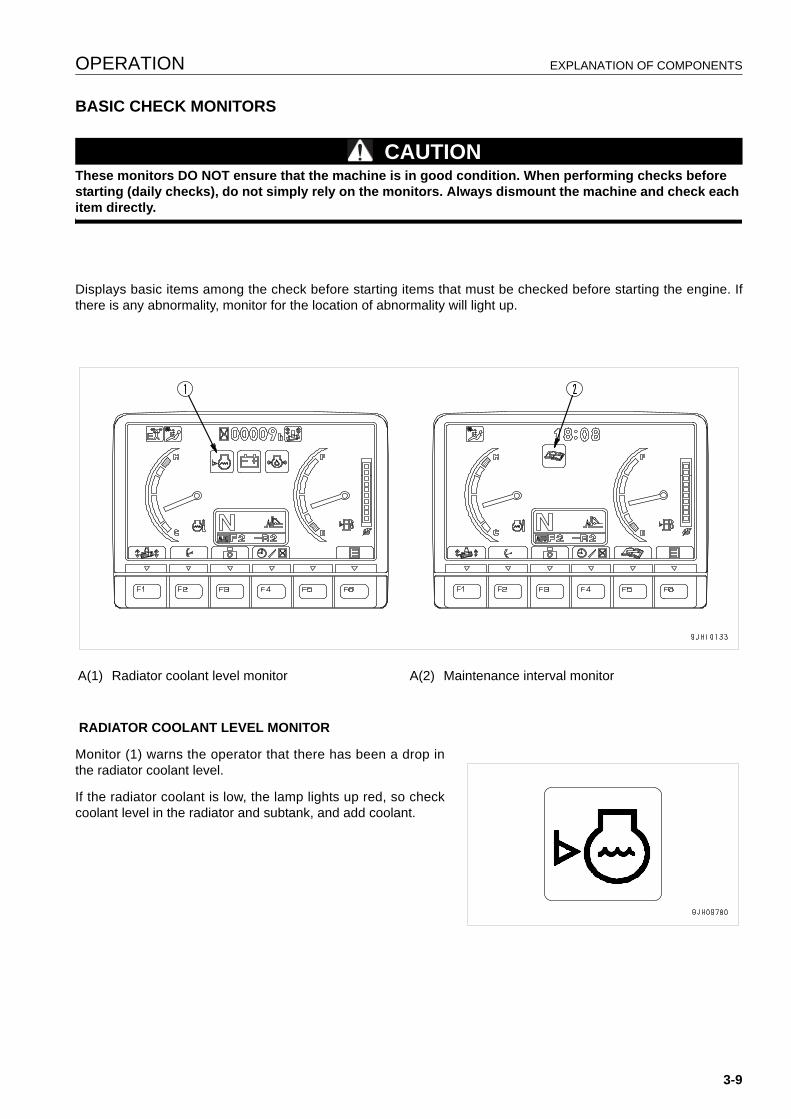
OPERATION EXPLANATION OF COMPONENTS
BASIC CHECK MONITORS 3
CAUTIONThese monitors DO NOT ensure that the machine is in good condition. When performing checks before starting (daily checks), do not simply rely on the monitors. Always dismount the machine and check each item directly.
Displays basic items among the check before starting items that must be checked before starting the engine. Ifthere is any abnormality, monitor for the location of abnormality will light up.
RADIATOR COOLANT LEVEL MONITOR
Monitor (1) warns the operator that there has been a drop inthe radiator coolant level.
If the radiator coolant is low, the lamp lights up red, so checkcoolant level in the radiator and subtank, and add coolant.
A(1) Radiator coolant level monitor A(2) Maintenance interval monitor
3-9
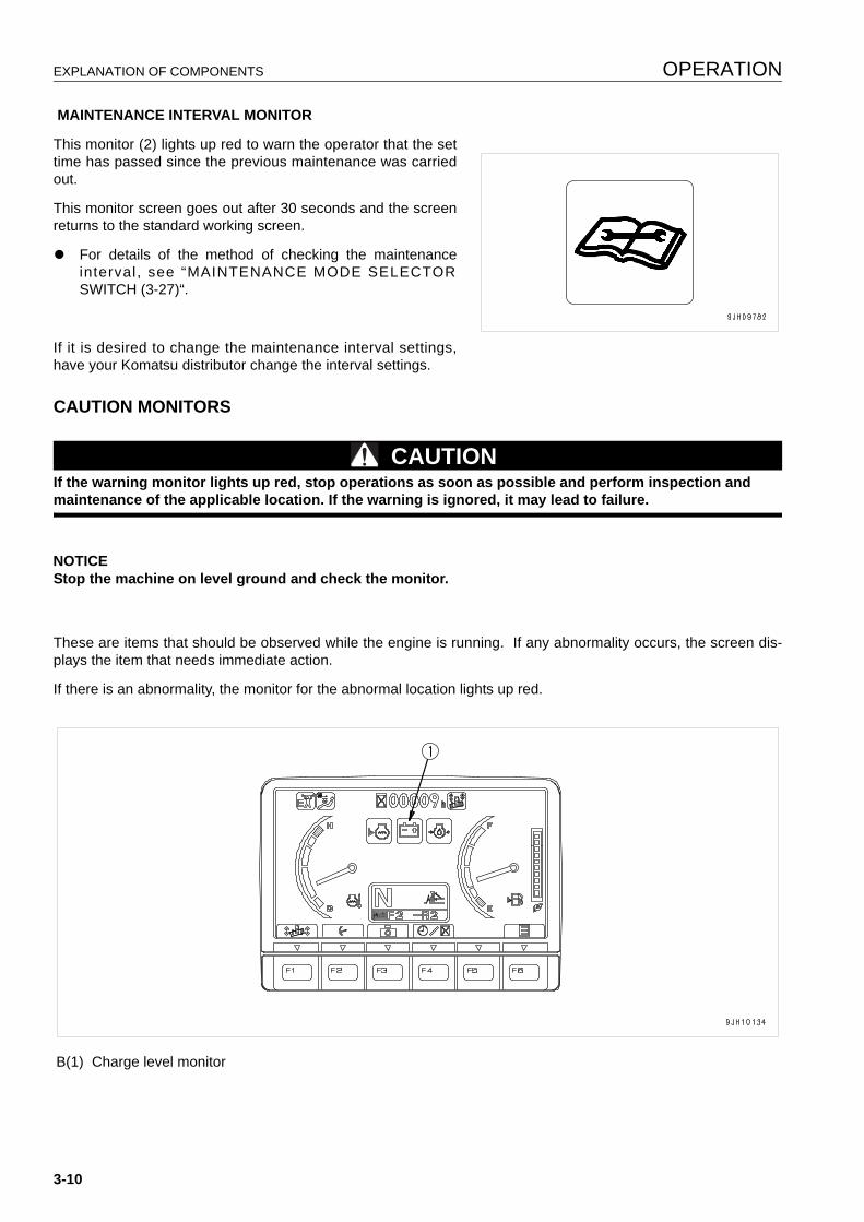
EXPLANATION OF COMPONENTS OPERATION
MAINTENANCE INTERVAL MONITOR
This monitor (2) lights up red to warn the operator that the settime has passed since the previous maintenance was carriedout.
This monitor screen goes out after 30 seconds and the screenreturns to the standard working screen.
q For details of the method of checking the maintenanceinterval, see “MAINTENANCE MODE SELECTORSWITCH (3-27)“.
If it is desired to change the maintenance interval settings,have your Komatsu distributor change the interval settings.
CAUTION MONITORS 3
CAUTIONIf the warning monitor lights up red, stop operations as soon as possible and perform inspection and maintenance of the applicable location. If the warning is ignored, it may lead to failure.
NOTICEStop the machine on level ground and check the monitor.
These are items that should be observed while the engine is running. If any abnormality occurs, the screen dis-plays the item that needs immediate action.
If there is an abnormality, the monitor for the abnormal location lights up red.
B(1) Charge level monitor
3-10
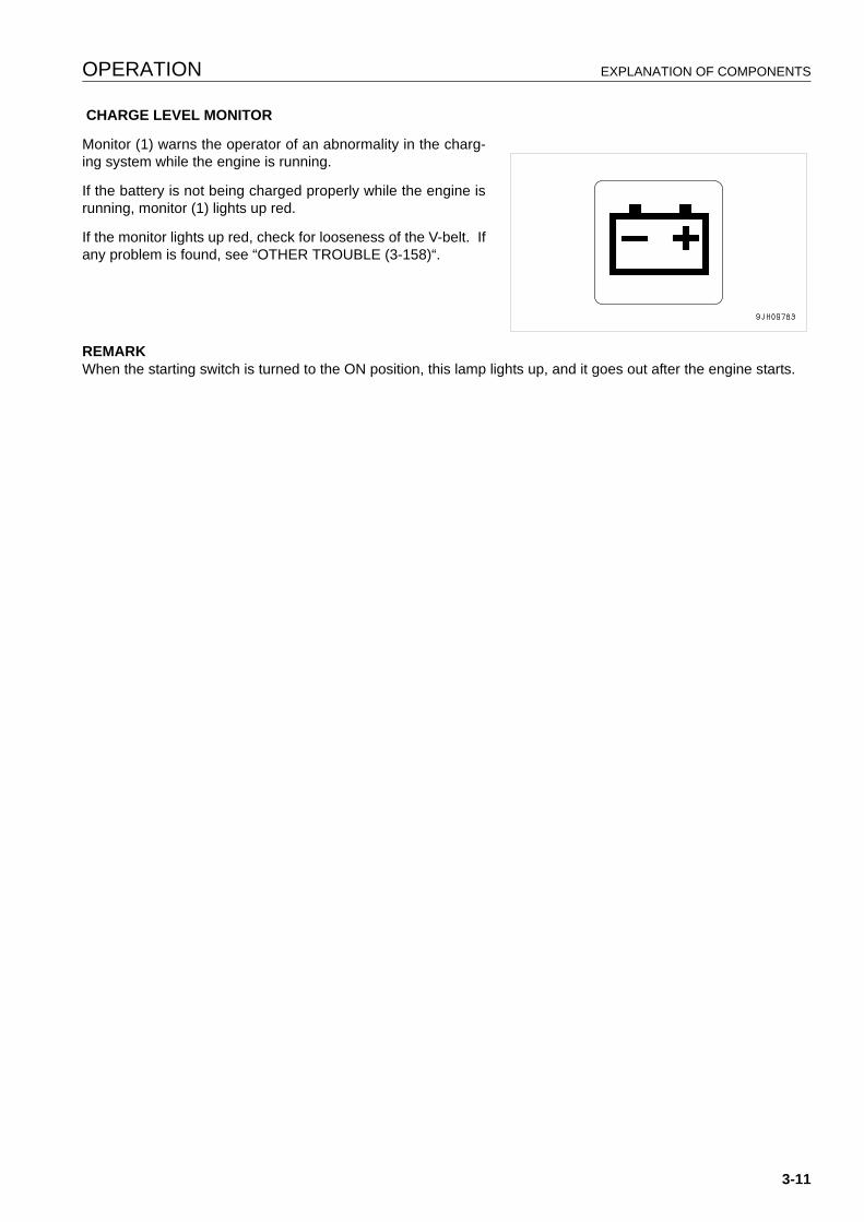
OPERATION EXPLANATION OF COMPONENTS
CHARGE LEVEL MONITOR
Monitor (1) warns the operator of an abnormality in the charg-ing system while the engine is running.
If the battery is not being charged properly while the engine isrunning, monitor (1) lights up red.
If the monitor lights up red, check for looseness of the V-belt. Ifany problem is found, see “OTHER TROUBLE (3-158)“.
REMARKWhen the starting switch is turned to the ON position, this lamp lights up, and it goes out after the engine starts.
3-11
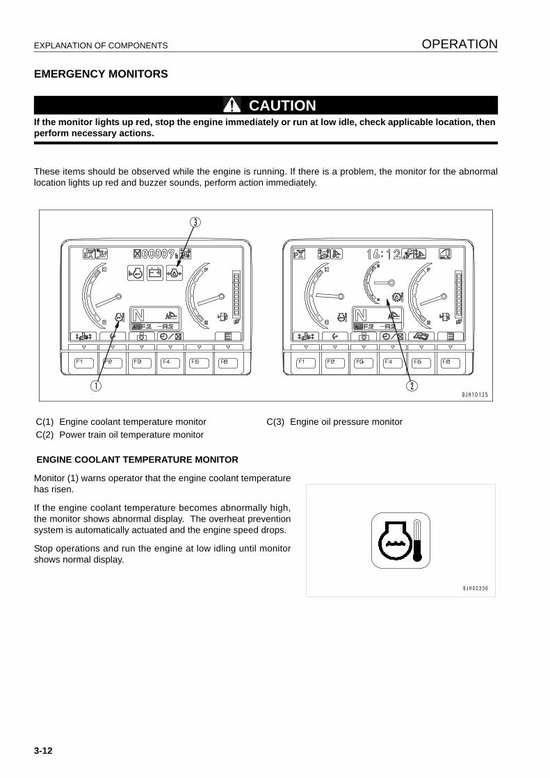
EXPLANATION OF COMPONENTS OPERATION
EMERGENCY MONITORS 3
CAUTIONIf the monitor lights up red, stop the engine immediately or run at low idle, check applicable location, then perform necessary actions.
These items should be observed while the engine is running. If there is a problem, the monitor for the abnormallocation lights up red and buzzer sounds, perform action immediately.
ENGINE COOLANT TEMPERATURE MONITOR
Monitor (1) warns operator that the engine coolant temperaturehas risen.
If the engine coolant temperature becomes abnormally high,the monitor shows abnormal display. The overheat preventionsystem is automatically actuated and the engine speed drops.
Stop operations and run the engine at low idling until monitorshows normal display.
C(1) Engine coolant temperature monitor C(3) Engine oil pressure monitorC(2) Power train oil temperature monitor
3-12
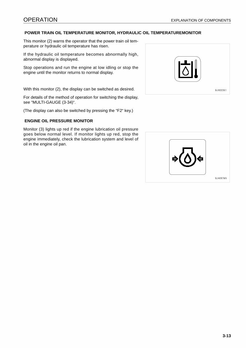
OPERATION EXPLANATION OF COMPONENTS
POWER TRAIN OIL TEMPERATURE MONITOR, HYDRAULIC OIL TEMPERATUREMONITOR
This monitor (2) warns the operator that the power train oil tem-perature or hydraulic oil temperature has risen.
If the hydraulic oil temperature becomes abnormally high,abnormal display is displayed.
Stop operations and run the engine at low idling or stop theengine until the monitor returns to normal display.
With this monitor (2), the display can be switched as desired.
For details of the method of operation for switching the display,see “MULTI-GAUGE (3-34)“.
(The display can also be switched by pressing the “F2“ key.)
ENGINE OIL PRESSURE MONITOR
Monitor (3) lights up red if the engine lubrication oil pressuregoes below normal level. If monitor lights up red, stop theengine immediately, check the lubrication system and level ofoil in the engine oil pan.
3-13
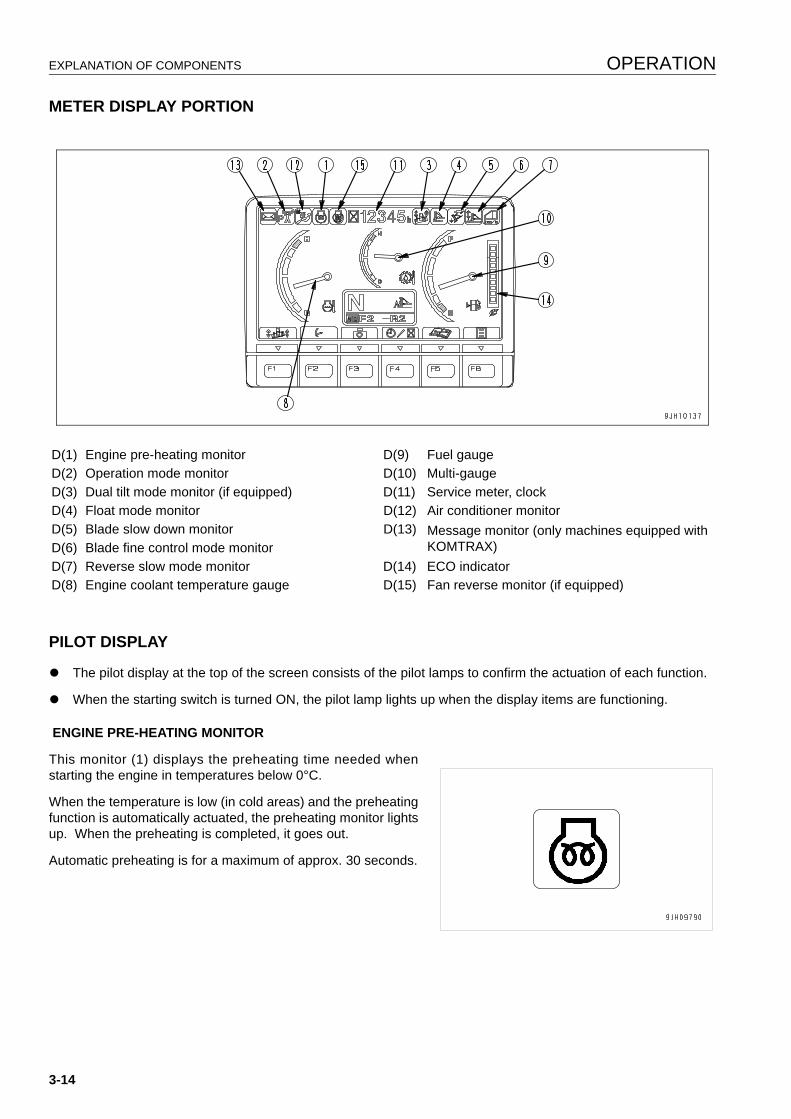
EXPLANATION OF COMPONENTS OPERATION
METER DISPLAY PORTION 3
PILOT DISPLAY 3
q The pilot display at the top of the screen consists of the pilot lamps to confirm the actuation of each function.
q When the starting switch is turned ON, the pilot lamp lights up when the display items are functioning.
ENGINE PRE-HEATING MONITOR
This monitor (1) displays the preheating time needed whenstarting the engine in temperatures below 0°C.
When the temperature is low (in cold areas) and the preheatingfunction is automatically actuated, the preheating monitor lightsup. When the preheating is completed, it goes out.
Automatic preheating is for a maximum of approx. 30 seconds.
D(1) Engine pre-heating monitor D(9) Fuel gaugeD(2) Operation mode monitor D(10) Multi-gaugeD(3) Dual tilt mode monitor (if equipped) D(11) Service meter, clockD(4) Float mode monitor D(12) Air conditioner monitorD(5) Blade slow down monitor D(13) Message monitor (only machines equipped with
KOMTRAX)D(6) Blade fine control mode monitorD(7) Reverse slow mode monitor D(14) ECO indicatorD(8) Engine coolant temperature gauge D(15) Fan reverse monitor (if equipped)
3-14
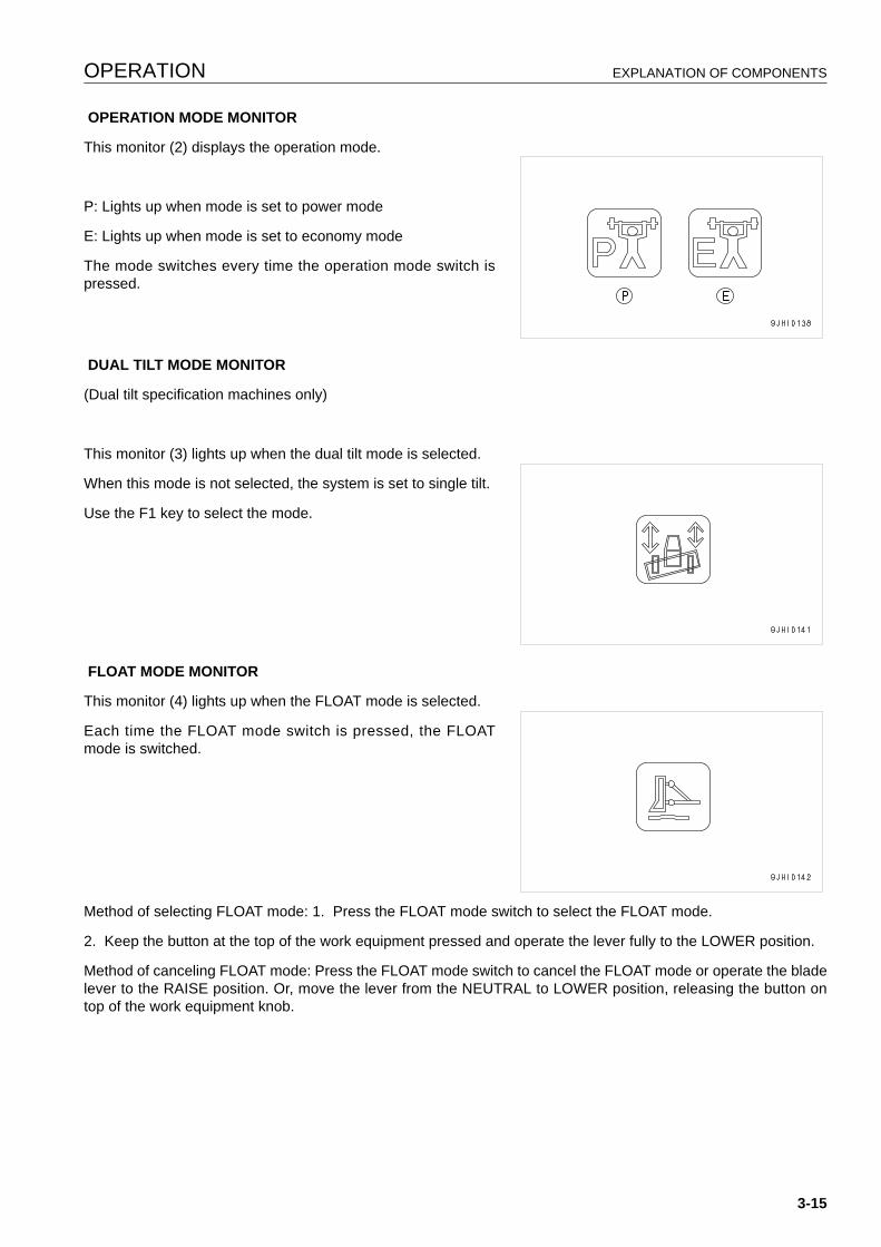
OPERATION EXPLANATION OF COMPONENTS
OPERATION MODE MONITOR
This monitor (2) displays the operation mode.
P: Lights up when mode is set to power mode
E: Lights up when mode is set to economy mode
The mode switches every time the operation mode switch ispressed.
DUAL TILT MODE MONITOR
(Dual tilt specification machines only)
This monitor (3) lights up when the dual tilt mode is selected.
When this mode is not selected, the system is set to single tilt.
Use the F1 key to select the mode.
FLOAT MODE MONITOR
This monitor (4) lights up when the FLOAT mode is selected.
Each time the FLOAT mode switch is pressed, the FLOATmode is switched.
Method of selecting FLOAT mode: 1. Press the FLOAT mode switch to select the FLOAT mode.
2. Keep the button at the top of the work equipment pressed and operate the lever fully to the LOWER position.
Method of canceling FLOAT mode: Press the FLOAT mode switch to cancel the FLOAT mode or operate the bladelever to the RAISE position. Or, move the lever from the NEUTRAL to LOWER position, releasing the button ontop of the work equipment knob.
3-15
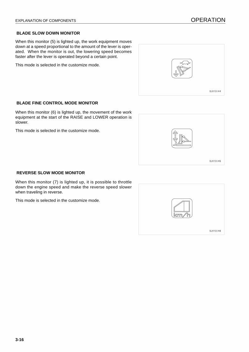
EXPLANATION OF COMPONENTS OPERATION
BLADE SLOW DOWN MONITOR
When this monitor (5) is lighted up, the work equipment movesdown at a speed proportional to the amount of the lever is oper-ated. When the monitor is out, the lowering speed becomesfaster after the lever is operated beyond a certain point.
This mode is selected in the customize mode.
BLADE FINE CONTROL MODE MONITOR
When this monitor (6) is lighted up, the movement of the workequipment at the start of the RAISE and LOWER operation isslower.
This mode is selected in the customize mode.
REVERSE SLOW MODE MONITOR
When this monitor (7) is lighted up, it is possible to throttledown the engine speed and make the reverse speed slowerwhen traveling in reverse.
This mode is selected in the customize mode.
3-16
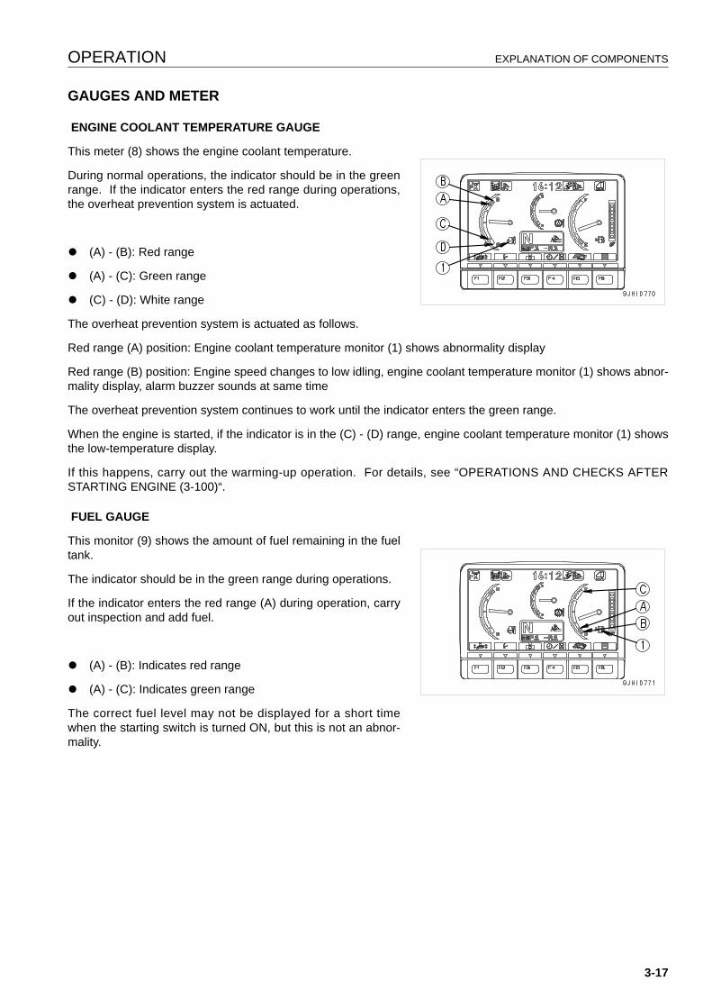
OPERATION EXPLANATION OF COMPONENTS
GAUGES AND METER 3
ENGINE COOLANT TEMPERATURE GAUGE
This meter (8) shows the engine coolant temperature.
During normal operations, the indicator should be in the greenrange. If the indicator enters the red range during operations,the overheat prevention system is actuated.
q (A) - (B): Red range
q (A) - (C): Green range
q (C) - (D): White range
The overheat prevention system is actuated as follows.
Red range (A) position: Engine coolant temperature monitor (1) shows abnormality display
Red range (B) position: Engine speed changes to low idling, engine coolant temperature monitor (1) shows abnor-mality display, alarm buzzer sounds at same time
The overheat prevention system continues to work until the indicator enters the green range.
When the engine is started, if the indicator is in the (C) - (D) range, engine coolant temperature monitor (1) showsthe low-temperature display.
If this happens, carry out the warming-up operation. For details, see “OPERATIONS AND CHECKS AFTERSTARTING ENGINE (3-100)“.
FUEL GAUGE
This monitor (9) shows the amount of fuel remaining in the fueltank.
The indicator should be in the green range during operations.
If the indicator enters the red range (A) during operation, carryout inspection and add fuel.
q (A) - (B): Indicates red range
q (A) - (C): Indicates green range
The correct fuel level may not be displayed for a short timewhen the starting switch is turned ON, but this is not an abnor-mality.
3-17
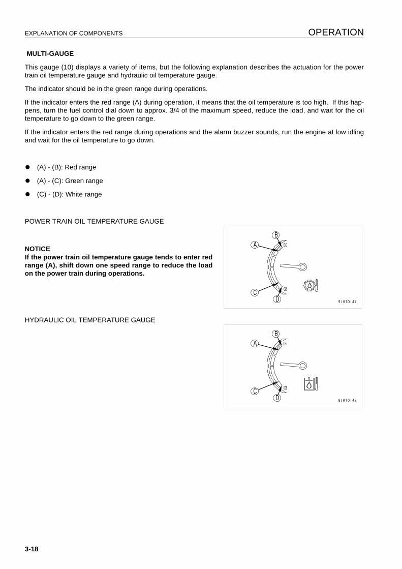
EXPLANATION OF COMPONENTS OPERATION
MULTI-GAUGE
This gauge (10) displays a variety of items, but the following explanation describes the actuation for the powertrain oil temperature gauge and hydraulic oil temperature gauge.
The indicator should be in the green range during operations.
If the indicator enters the red range (A) during operation, it means that the oil temperature is too high. If this hap-pens, turn the fuel control dial down to approx. 3/4 of the maximum speed, reduce the load, and wait for the oiltemperature to go down to the green range.
If the indicator enters the red range during operations and the alarm buzzer sounds, run the engine at low idlingand wait for the oil temperature to go down.
q (A) - (B): Red range
q (A) - (C): Green range
q (C) - (D): White range
POWER TRAIN OIL TEMPERATURE GAUGE
NOTICEIf the power train oil temperature gauge tends to enter redrange (A), shift down one speed range to reduce the loadon the power train during operations.
HYDRAULIC OIL TEMPERATURE GAUGE
3-18
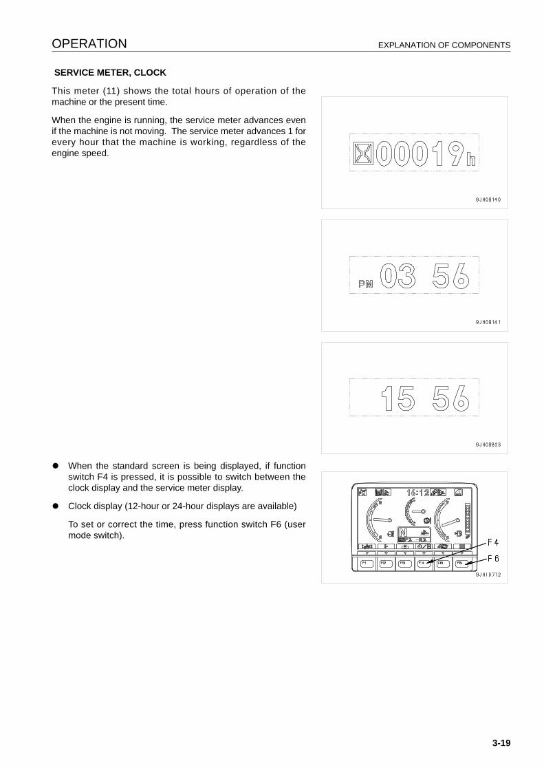
OPERATION EXPLANATION OF COMPONENTS
SERVICE METER, CLOCK
This meter (11) shows the total hours of operation of themachine or the present time.
When the engine is running, the service meter advances evenif the machine is not moving. The service meter advances 1 forevery hour that the machine is working, regardless of theengine speed.
q When the standard screen is being displayed, if functionswitch F4 is pressed, it is possible to switch between theclock display and the service meter display.
q Clock display (12-hour or 24-hour displays are available)
To set or correct the time, press function switch F6 (usermode switch).
3-19
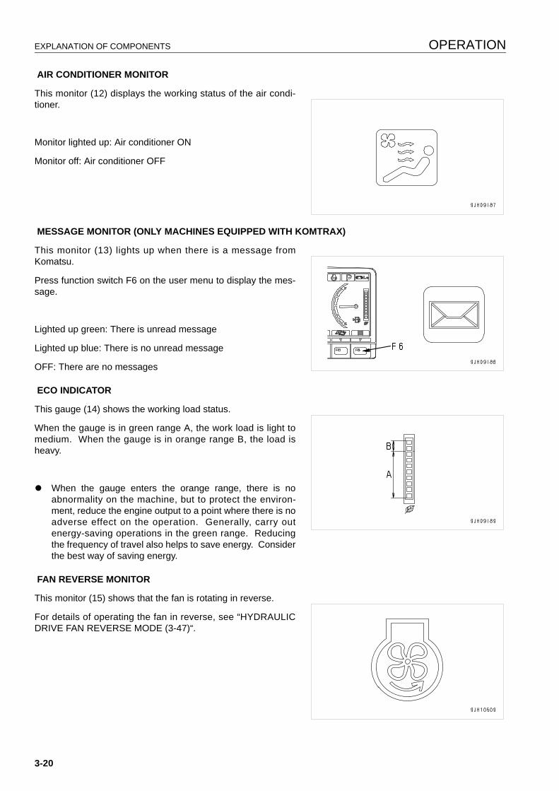
EXPLANATION OF COMPONENTS OPERATION
AIR CONDITIONER MONITOR
This monitor (12) displays the working status of the air condi-tioner.
Monitor lighted up: Air conditioner ON
Monitor off: Air conditioner OFF
MESSAGE MONITOR (ONLY MACHINES EQUIPPED WITH KOMTRAX)
This monitor (13) lights up when there is a message fromKomatsu.
Press function switch F6 on the user menu to display the mes-sage.
Lighted up green: There is unread message
Lighted up blue: There is no unread message
OFF: There are no messages
ECO INDICATOR
This gauge (14) shows the working load status.
When the gauge is in green range A, the work load is light tomedium. When the gauge is in orange range B, the load isheavy.
q When the gauge enters the orange range, there is noabnormality on the machine, but to protect the environ-ment, reduce the engine output to a point where there is noadverse effect on the operation. Generally, carry outenergy-saving operations in the green range. Reducingthe frequency of travel also helps to save energy. Considerthe best way of saving energy.
FAN REVERSE MONITOR
This monitor (15) shows that the fan is rotating in reverse.
For details of operating the fan in reverse, see “HYDRAULICDRIVE FAN REVERSE MODE (3-47)“.
3-20
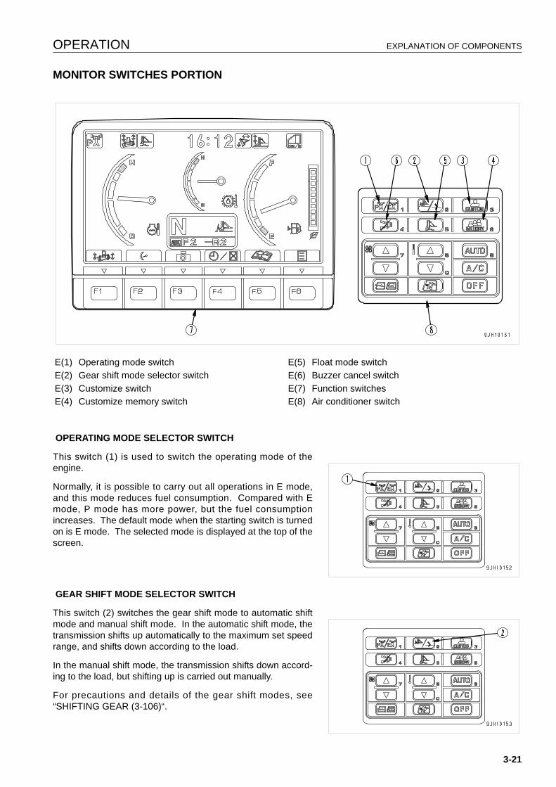
OPERATION EXPLANATION OF COMPONENTS
MONITOR SWITCHES PORTION 3
OPERATING MODE SELECTOR SWITCH
This switch (1) is used to switch the operating mode of theengine.
Normally, it is possible to carry out all operations in E mode,and this mode reduces fuel consumption. Compared with Emode, P mode has more power, but the fuel consumptionincreases. The default mode when the starting switch is turnedon is E mode. The selected mode is displayed at the top of thescreen.
GEAR SHIFT MODE SELECTOR SWITCH
This switch (2) switches the gear shift mode to automatic shiftmode and manual shift mode. In the automatic shift mode, thetransmission shifts up automatically to the maximum set speedrange, and shifts down according to the load.
In the manual shift mode, the transmission shifts down accord-ing to the load, but shifting up is carried out manually.
For precautions and details of the gear shift modes, see“SHIFTING GEAR (3-106)“.
E(1) Operating mode switch E(5) Float mode switchE(2) Gear shift mode selector switch E(6) Buzzer cancel switchE(3) Customize switch E(7) Function switchesE(4) Customize memory switch E(8) Air conditioner switch
3-21
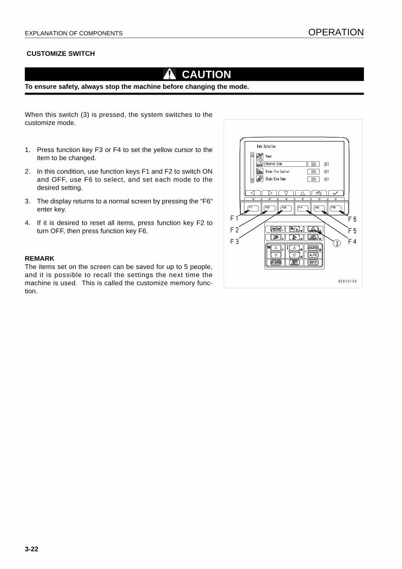
EXPLANATION OF COMPONENTS OPERATION
CUSTOMIZE SWITCH
CAUTIONTo ensure safety, always stop the machine before changing the mode.
When this switch (3) is pressed, the system switches to thecustomize mode.
1. Press function key F3 or F4 to set the yellow cursor to theitem to be changed.
2. In this condition, use function keys F1 and F2 to switch ONand OFF, use F6 to select, and set each mode to thedesired setting.
3. The display returns to a normal screen by pressing the “F6“enter key.
4. If it is desired to reset all items, press function key F2 toturn OFF, then press function key F6.
REMARKThe items set on the screen can be saved for up to 5 people,and it is possible to recall the settings the next time themachine is used. This is called the customize memory func-tion.
3-22
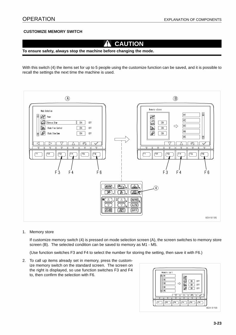
OPERATION EXPLANATION OF COMPONENTS
CUSTOMIZE MEMORY SWITCH
CAUTIONTo ensure safety, always stop the machine before changing the mode.
With this switch (4) the items set for up to 5 people using the customize function can be saved, and it is possible torecall the settings the next time the machine is used.
1. Memory store
If customize memory switch (4) is pressed on mode selection screen (A), the screen switches to memory storescreen (B). The selected condition can be saved to memory as M1 - M5.
(Use function switches F3 and F4 to select the number for storing the setting, then save it with F6.)
2. To call up items already set in memory, press the custom-ize memory switch on the standard screen. The screen onthe right is displayed, so use function switches F3 and F4to, then confirm the selection with F6.
3-23
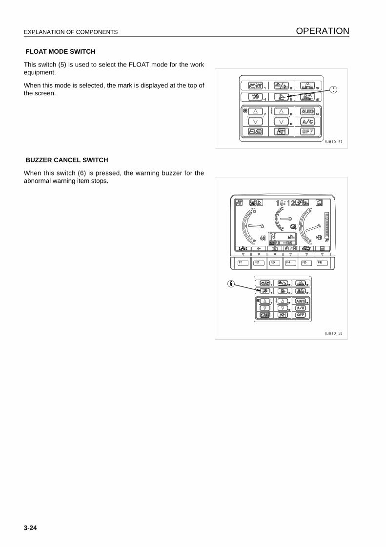
EXPLANATION OF COMPONENTS OPERATION
FLOAT MODE SWITCH
This switch (5) is used to select the FLOAT mode for the workequipment.
When this mode is selected, the mark is displayed at the top ofthe screen.
BUZZER CANCEL SWITCH
When this switch (6) is pressed, the warning buzzer for theabnormal warning item stops.
3-24
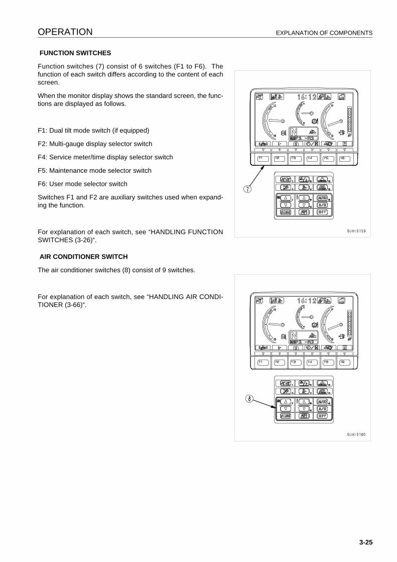
OPERATION EXPLANATION OF COMPONENTS
FUNCTION SWITCHES
Function switches (7) consist of 6 switches (F1 to F6). Thefunction of each switch differs according to the content of eachscreen.
When the monitor display shows the standard screen, the func-tions are displayed as follows.
F1: Dual tilt mode switch (if equipped)
F2: Multi-gauge display selector switch
F4: Service meter/time display selector switch
F5: Maintenance mode selector switch
F6: User mode selector switch
Switches F1 and F2 are auxiliary switches used when expand-ing the function.
For explanation of each switch, see “HANDLING FUNCTIONSWITCHES (3-26)“.
AIR CONDITIONER SWITCH
The air conditioner switches (8) consist of 9 switches.
For explanation of each switch, see “HANDLING AIR CONDI-TIONER (3-66)“.
3-25
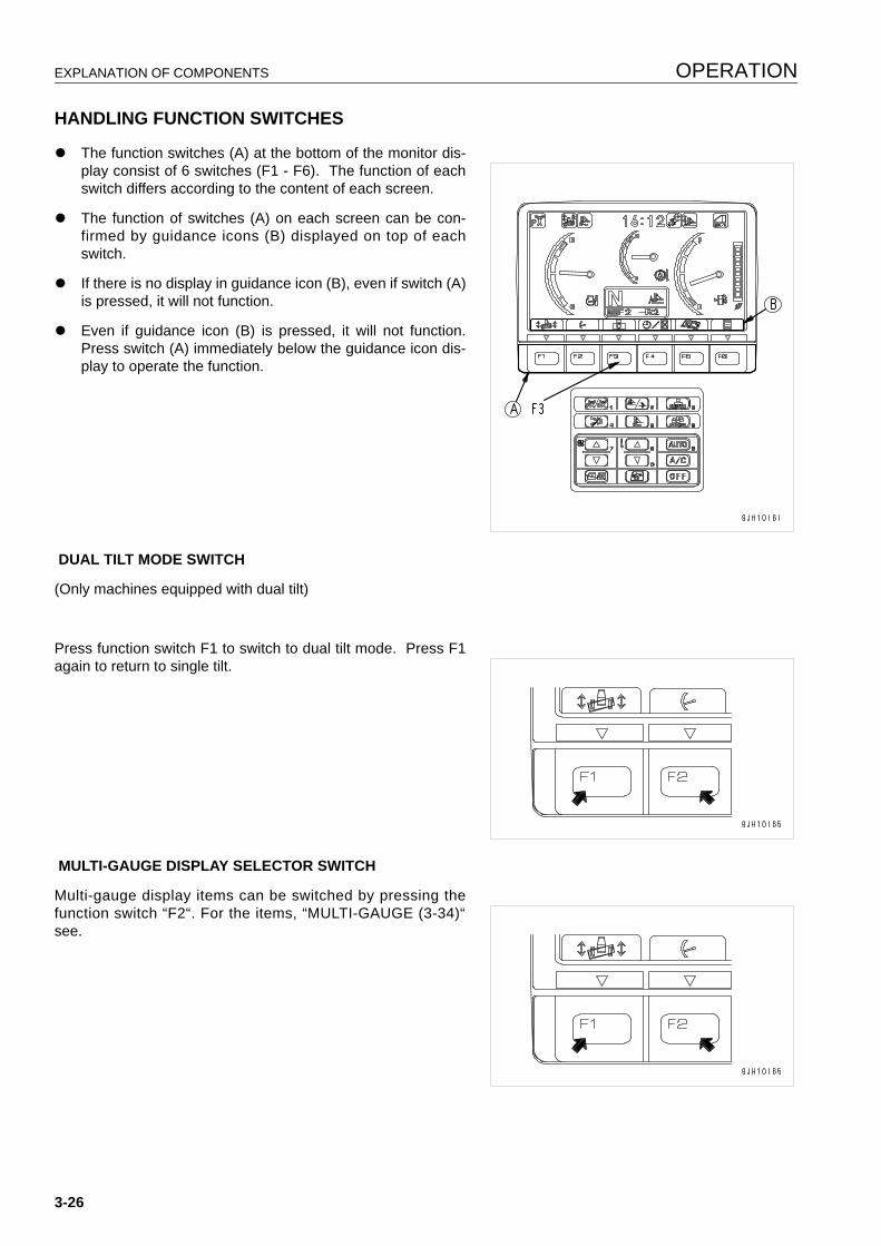
EXPLANATION OF COMPONENTS OPERATION
HANDLING FUNCTION SWITCHES 3
q The function switches (A) at the bottom of the monitor dis-play consist of 6 switches (F1 - F6). The function of eachswitch differs according to the content of each screen.
q The function of switches (A) on each screen can be con-firmed by guidance icons (B) displayed on top of eachswitch.
q If there is no display in guidance icon (B), even if switch (A)is pressed, it will not function.
q Even if guidance icon (B) is pressed, it will not function.Press switch (A) immediately below the guidance icon dis-play to operate the function.
DUAL TILT MODE SWITCH
(Only machines equipped with dual tilt)
Press function switch F1 to switch to dual tilt mode. Press F1again to return to single tilt.
MULTI-GAUGE DISPLAY SELECTOR SWITCH
Multi-gauge display items can be switched by pressing thefunction switch “F2“. For the items, “MULTI-GAUGE (3-34)“see.
3-26

OPERATION EXPLANATION OF COMPONENTS
SERVICE METER/CLOCK DISPLAY SELECTOR SWITCHOn the standard screen, it is possible to press switch F4 toswitch the service meter and clock display at the top of themonitor display.
q When the time is being displayed, press switch F4 toswitch to the service meter display.
When the service meter is being displayed, press switchF4 to switch to the time display.
MAINTENANCE MODE SELECTOR SWITCHWhen switch F5 is pressed on the standard screen, the monitordisplay screen switches to the maintenance mode screen.
3-27
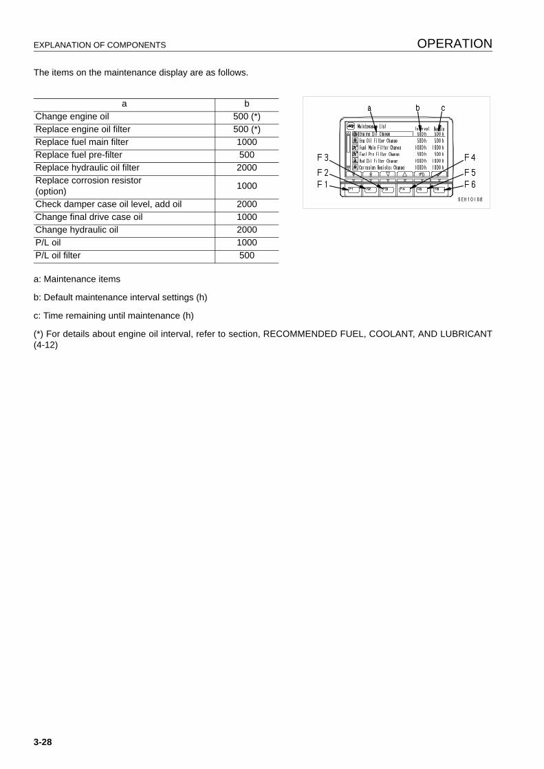
EXPLANATION OF COMPONENTS OPERATION
The items on the maintenance display are as follows.
a: Maintenance items
b: Default maintenance interval settings (h)
c: Time remaining until maintenance (h)
(*) For details about engine oil interval, refer to section, RECOMMENDED FUEL, COOLANT, AND LUBRICANT(4-12)
a bChange engine oil 500 (*)Replace engine oil filter 500 (*)Replace fuel main filter 1000Replace fuel pre-filter 500Replace hydraulic oil filter 2000Replace corrosion resistor(option) 1000
Check damper case oil level, add oil 2000Change final drive case oil 1000Change hydraulic oil 2000P/L oil 1000P/L oil filter 500
3-28
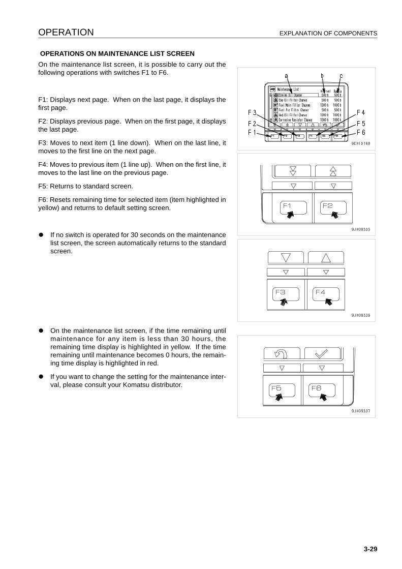
OPERATION EXPLANATION OF COMPONENTS
OPERATIONS ON MAINTENANCE LIST SCREENOn the maintenance list screen, it is possible to carry out thefollowing operations with switches F1 to F6.
F1: Displays next page. When on the last page, it displays thefirst page.
F2: Displays previous page. When on the first page, it displaysthe last page.
F3: Moves to next item (1 line down). When on the last line, itmoves to the first line on the next page.
F4: Moves to previous item (1 line up). When on the first line, itmoves to the last line on the previous page.
F5: Returns to standard screen.
F6: Resets remaining time for selected item (item highlighted inyellow) and returns to default setting screen.
q If no switch is operated for 30 seconds on the maintenancelist screen, the screen automatically returns to the standardscreen.
q On the maintenance list screen, if the time remaining untilmaintenance for any item is less than 30 hours, theremaining time display is highlighted in yellow. If the timeremaining until maintenance becomes 0 hours, the remain-ing time display is highlighted in red.
q If you want to change the setting for the maintenance inter-val, please consult your Komatsu distributor.
3-29
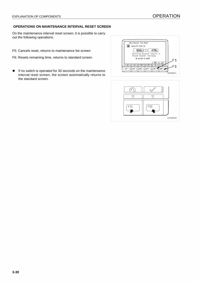
EXPLANATION OF COMPONENTS OPERATION
OPERATIONS ON MAINTENANCE INTERVAL RESET SCREEN
On the maintenance interval reset screen, it is possible to carryout the following operations.
F5: Cancels reset, returns to maintenance list screen
F6: Resets remaining time, returns to standard screen
q If no switch is operated for 30 seconds on the maintenanceinterval reset screen, the screen automatically returns tothe standard screen.
3-30
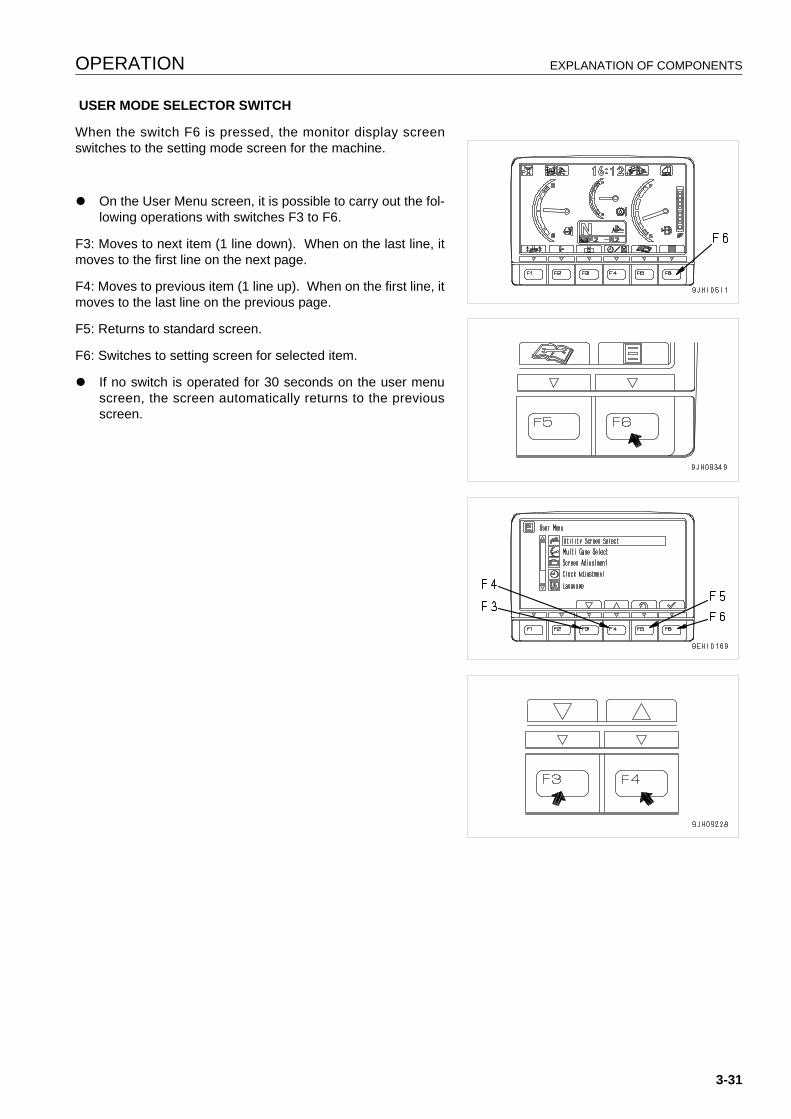
OPERATION EXPLANATION OF COMPONENTS
USER MODE SELECTOR SWITCH
When the switch F6 is pressed, the monitor display screenswitches to the setting mode screen for the machine.
q On the User Menu screen, it is possible to carry out the fol-lowing operations with switches F3 to F6.
F3: Moves to next item (1 line down). When on the last line, itmoves to the first line on the next page.
F4: Moves to previous item (1 line up). When on the first line, itmoves to the last line on the previous page.
F5: Returns to standard screen.
F6: Switches to setting screen for selected item.
q If no switch is operated for 30 seconds on the user menuscreen, the screen automatically returns to the previousscreen.
3-31
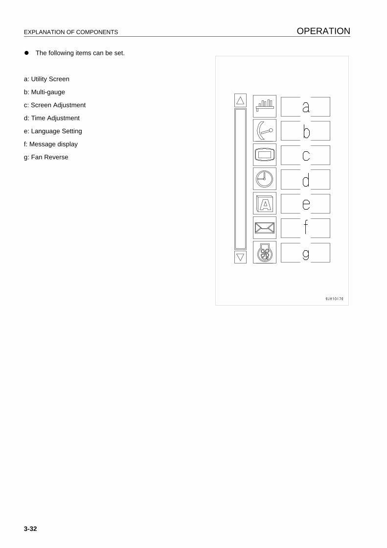
EXPLANATION OF COMPONENTS OPERATION
q The following items can be set.
a: Utility Screen
b: Multi-gauge
c: Screen Adjustment
d: Time Adjustment
e: Language Setting
f: Message display
g: Fan Reverse
3-32
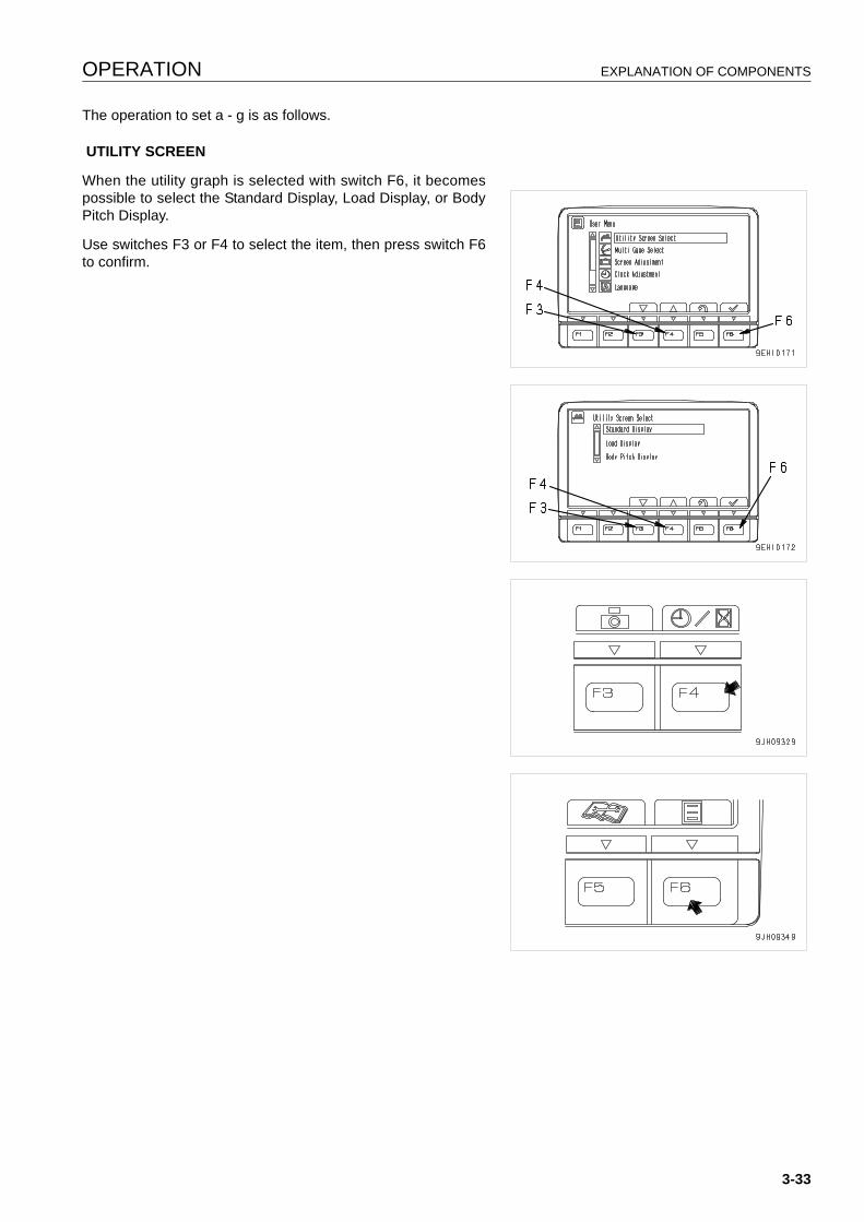
OPERATION EXPLANATION OF COMPONENTS
The operation to set a - g is as follows.
UTILITY SCREEN
When the utility graph is selected with switch F6, it becomespossible to select the Standard Display, Load Display, or BodyPitch Display.
Use switches F3 or F4 to select the item, then press switch F6to confirm.
3-33
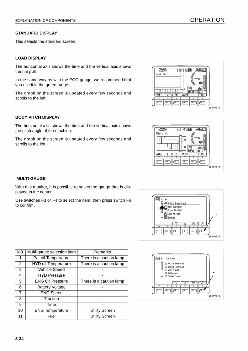
EXPLANATION OF COMPONENTS OPERATION
STANDARD DISPLAY
This selects the standard screen.
LOAD DISPLAY
The horizontal axis shows the time and the vertical axis showsthe rim pull.
In the same way as with the ECO gauge, we recommend thatyou use it in the green range.
The graph on the screen is updated every few seconds andscrolls to the left.
BODY PITCH DISPLAY
The horizontal axis shows the time and the vertical axis showsthe pitch angle of the machine.
The graph on the screen is updated every few seconds andscrolls to the left.
MULTI-GAUGE
With this monitor, it is possible to select the gauge that is dis-played in the center.
Use switches F3 or F4 to select the item, then press switch F6to confirm.
NO. Multi-gauge selection item Remarks1 P/L oil Temperature There is a caution lamp2 HYD oil Temperature There is a caution lamp3 Vehicle Speed -4 HYD Pressure -5 ENG Oil Pressure There is a caution lamp6 Battery Voltage -7 ENG Speed -8 Traction -9 Time -
10 ENG Temperature Utility Screen11 Fuel Utility Screen
3-34
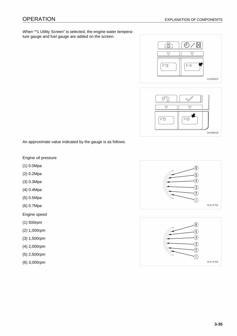
OPERATION EXPLANATION OF COMPONENTS
When “*1 Utility Screen“ is selected, the engine water tempera-ture gauge and fuel gauge are added on the screen.
An approximate value indicated by the gauge is as follows.
Engine oil pressure
(1) 0.0Mpa
(2) 0.2Mpa
(3) 0.3Mpa
(4) 0.4Mpa
(5) 0.5Mpa
(6) 0.7Mpa
Engine speed
(1) 500rpm
(2) 1,000rpm
(3) 1,500rpm
(4) 2,000rpm
(5) 2,500rpm
(6) 3,000rpm
3-35
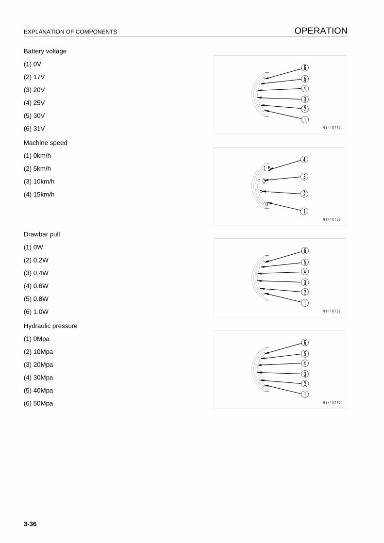
EXPLANATION OF COMPONENTS OPERATION
Battery voltage
(1) 0V
(2) 17V
(3) 20V
(4) 25V
(5) 30V
(6) 31V
Machine speed
(1) 0km/h
(2) 5km/h
(3) 10km/h
(4) 15km/h
Drawbar pull
(1) 0W
(2) 0.2W
(3) 0.4W
(4) 0.6W
(5) 0.8W
(6) 1.0W
Hydraulic pressure
(1) 0Mpa
(2) 10Mpa
(3) 20Mpa
(4) 30Mpa
(5) 40Mpa
(6) 50Mpa
3-36
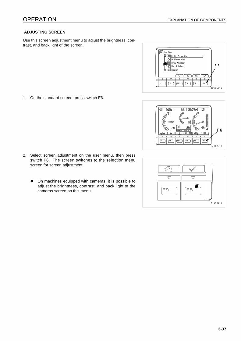
OPERATION EXPLANATION OF COMPONENTS
ADJUSTING SCREEN
Use this screen adjustment menu to adjust the brightness, con-trast, and back light of the screen.
1. On the standard screen, press switch F6.
2. Select screen adjustment on the user menu, then pressswitch F6. The screen switches to the selection menuscreen for screen adjustment.
q On machines equipped with cameras, it is possible toadjust the brightness, contrast, and back light of thecameras screen on this menu.
3-37
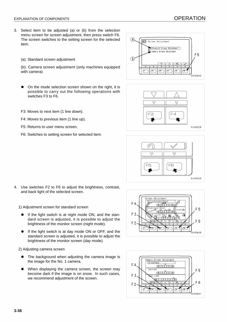
EXPLANATION OF COMPONENTS OPERATION
3. Select item to be adjusted (a) or (b) from the selectionmenu screen for screen adjustment, then press switch F6.The screen switches to the setting screen for the selecteditem.
(a): Standard screen adjustment
(b): Camera screen adjustment (only machines equippedwith camera)
q On the mode selection screen shown on the right, it ispossible to carry out the following operations withswitches F3 to F6.
F3: Moves to next item (1 line down).
F4: Moves to previous item (1 line up).
F5: Returns to user menu screen.
F6: Switches to setting screen for selected item.
4. Use switches F2 to F6 to adjust the brightness, contrast,and back light of the selected screen.
1) Adjustment screen for standard screen
q If the light switch is at night mode ON, and the stan-dard screen is adjusted, it is possible to adjust thebrightness of the monitor screen (night mode).
q If the light switch is at day mode ON or OFF, and thestandard screen is adjusted, it is possible to adjust thebrightness of the monitor screen (day mode).
2) Adjusting camera screen
q The background when adjusting the camera image isthe image for the No. 1 camera.
q When displaying the camera screen, the screen maybecome dark if the image is on snow. In such cases,we recommend adjustment of the screen.
3-38

OPERATION EXPLANATION OF COMPONENTS
On the screen for Items 1) and 2), it is possible to carry out thefollowing operations with switches F2 to F6.
F2: Resets all adjusted values to default value
F3: Indicator of selected item moves 1 segment to left.
F4: Indicator of selected item moves 1 segment to right.
F5: Returns to user menu.
F6: Accepts change and switches to next item setting.
CLOCK ADJUSTMENT
On this clock adjustment menu, it is possible to change the set-ting of the clock displayed on the pilot monitor of the standarddisplay.
3-39
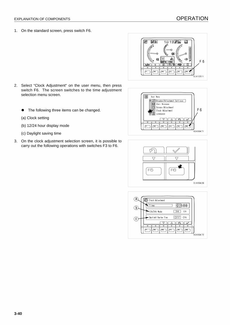
EXPLANATION OF COMPONENTS OPERATION
1. On the standard screen, press switch F6.
2. Select “Clock Adjustment“ on the user menu, then pressswitch F6. The screen switches to the time adjustmentselection menu screen.
q The following three items can be changed.
(a) Clock setting
(b) 12/24 hour display mode
(c) Daylight saving time
3. On the clock adjustment selection screen, it is possible tocarry out the following operations with switches F3 to F6.
3-40

OPERATION EXPLANATION OF COMPONENTS
q Time
Adjust the hour setting.
1) If “Time“ (a) is not highlighted in yellow, press switch F6 tohighlight “Time“ (a) in yellow. When this is done, hour dis-play (b) changes to orange.
Adjust hour display (b) with the switches as follows. If it isnot necessary to change the hour setting, press switch F6.
F3: Time advances 1 hour.
F4: Time goes back 1 hour.
F5: Cancels change and returns to user menu.
F6: Accepts change and goes to setting for minutes.
2) When minute display (c) is highlighted in orange, operatethe switches as follows to adjust minute display (c).
If it is not necessary to change the minute setting, pressswitch F6. If the time has been changed, always pressswitch F6.
F3: Time advances 1 minute.
F4: Time goes back 1 minute.
F5: Cancels change and returns to user menu.
F6: Accepts change and goes to setting for 12/24 hour dis-play mode.
3-41

EXPLANATION OF COMPONENTS OPERATION
q 12h/24h Mode
Choose either a 12-hour display (am/pm) or a 24-hour dis-play.
(b): 24-hour display
(c): 12-hour display (am/pm)
1) If “12h/24h Mode“ (a) is not highlighted in yellow, pressswitch F6 to highlight “12h/24h Mode“ (a) in yellow.
2) Change the “12h/24h mode“ with the switches as follows.
The selected display mode (b) or (c) is highlighted in green.
F3: Moves 1 item to left.
F4: Moves 1 item to right.
F5: Cancels change and returns to user menu.
F6: Accepts change and goes to setting for “Daylight SavingTime“.
If the setting has been changed, always press switch F6.
3-42
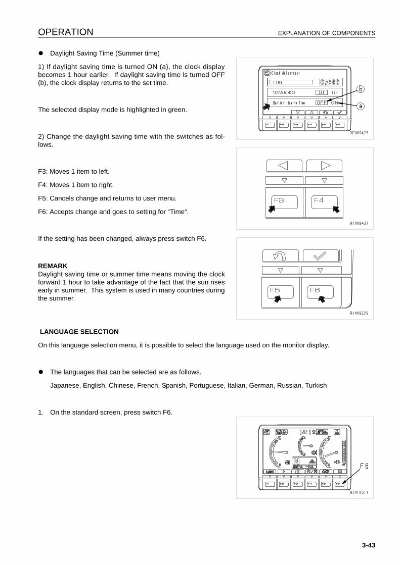
OPERATION EXPLANATION OF COMPONENTS
q Daylight Saving Time (Summer time)
1) If daylight saving time is turned ON (a), the clock displaybecomes 1 hour earlier. If daylight saving time is turned OFF(b), the clock display returns to the set time.
The selected display mode is highlighted in green.
2) Change the daylight saving time with the switches as fol-lows.
F3: Moves 1 item to left.
F4: Moves 1 item to right.
F5: Cancels change and returns to user menu.
F6: Accepts change and goes to setting for “Time“.
If the setting has been changed, always press switch F6.
REMARKDaylight saving time or summer time means moving the clockforward 1 hour to take advantage of the fact that the sun risesearly in summer. This system is used in many countries duringthe summer.
LANGUAGE SELECTION
On this language selection menu, it is possible to select the language used on the monitor display.
q The languages that can be selected are as follows.
Japanese, English, Chinese, French, Spanish, Portuguese, Italian, German, Russian, Turkish
1. On the standard screen, press switch F6.
3-43
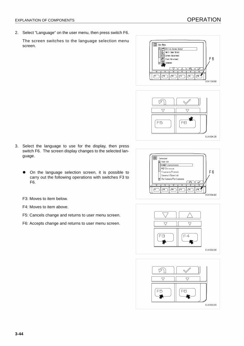
EXPLANATION OF COMPONENTS OPERATION
2. Select “Language“ on the user menu, then press switch F6.
The screen switches to the language selection menuscreen.
3. Select the language to use for the display, then pressswitch F6. The screen display changes to the selected lan-guage.
q On the language selection screen, it is possible tocarry out the following operations with switches F3 toF6.
F3: Moves to item below.
F4: Moves to item above.
F5: Cancels change and returns to user menu screen.
F6: Accepts change and returns to user menu screen.
3-44
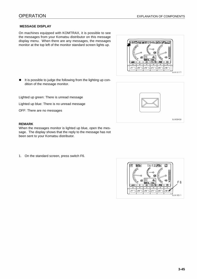
OPERATION EXPLANATION OF COMPONENTS
MESSAGE DISPLAY
On machines equipped with KOMTRAX, it is possible to seethe messages from your Komatsu distributor on this messagedisplay menu. When there are any messages, the messagesmonitor at the top left of the monitor standard screen lights up.
q It is possible to judge the following from the lighting up con-dition of the message monitor.
Lighted up green: There is unread message
Lighted up blue: There is no unread message
OFF: There are no messages
REMARKWhen the messages monitor is lighted up blue, open the mes-sage. The display shows that the reply to the message has notbeen sent to your Komatsu distributor.
1. On the standard screen, press switch F6.
3-45
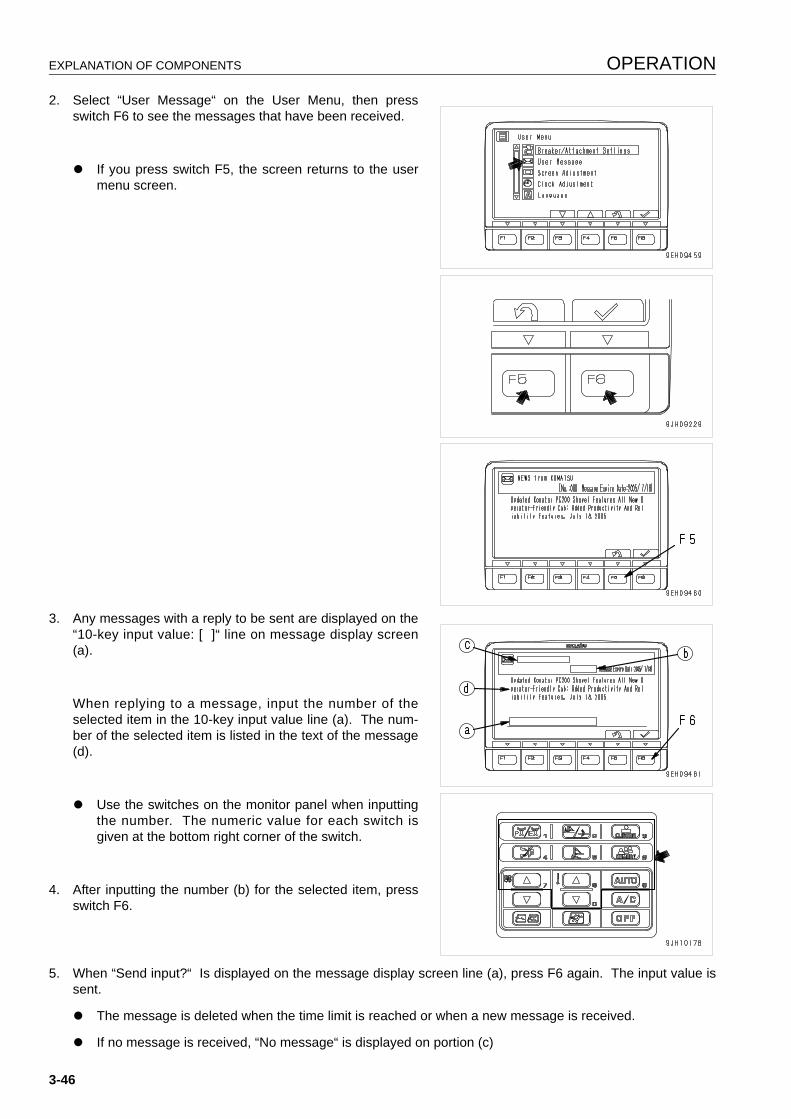
EXPLANATION OF COMPONENTS OPERATION
2. Select “User Message“ on the User Menu, then pressswitch F6 to see the messages that have been received.
q If you press switch F5, the screen returns to the usermenu screen.
3. Any messages with a reply to be sent are displayed on the“10-key input value: [ ]“ line on message display screen(a).
When replying to a message, input the number of theselected item in the 10-key input value line (a). The num-ber of the selected item is listed in the text of the message(d).
q Use the switches on the monitor panel when inputtingthe number. The numeric value for each switch isgiven at the bottom right corner of the switch.
4. After inputting the number (b) for the selected item, pressswitch F6.
5. When “Send input?“ Is displayed on the message display screen line (a), press F6 again. The input value issent.
q The message is deleted when the time limit is reached or when a new message is received.
q If no message is received, “No message“ is displayed on portion (c)
3-46
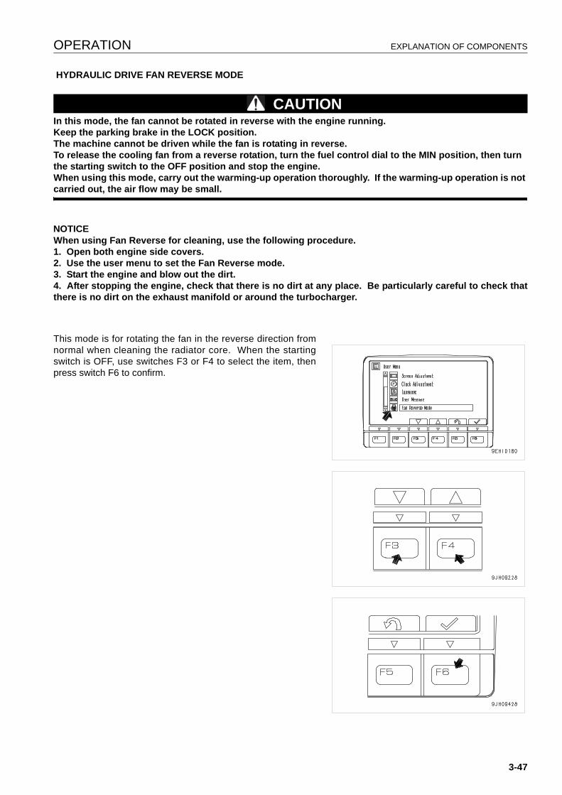
OPERATION EXPLANATION OF COMPONENTS
HYDRAULIC DRIVE FAN REVERSE MODE
CAUTIONIn this mode, the fan cannot be rotated in reverse with the engine running.Keep the parking brake in the LOCK position.The machine cannot be driven while the fan is rotating in reverse.To release the cooling fan from a reverse rotation, turn the fuel control dial to the MIN position, then turn the starting switch to the OFF position and stop the engine.When using this mode, carry out the warming-up operation thoroughly. If the warming-up operation is not carried out, the air flow may be small.
NOTICEWhen using Fan Reverse for cleaning, use the following procedure.1. Open both engine side covers.2. Use the user menu to set the Fan Reverse mode.3. Start the engine and blow out the dirt.4. After stopping the engine, check that there is no dirt at any place. Be particularly careful to check thatthere is no dirt on the exhaust manifold or around the turbocharger.
This mode is for rotating the fan in the reverse direction fromnormal when cleaning the radiator core. When the startingswitch is OFF, use switches F3 or F4 to select the item, thenpress switch F6 to confirm.
3-47
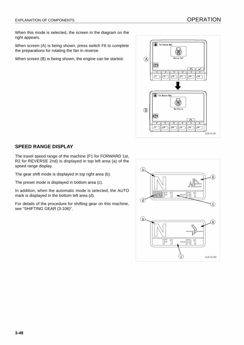
EXPLANATION OF COMPONENTS OPERATION
When this mode is selected, the screen in the diagram on theright appears.
When screen (A) is being shown, press switch F6 to completethe preparations for rotating the fan in reverse.
When screen (B) is being shown, the engine can be started.
SPEED RANGE DISPLAY 3
The travel speed range of the machine (F1 for FORWARD 1st,R2 for REVERSE 2nd) is displayed in top left area (a) of thespeed range display.
The gear shift mode is displayed in top right area (b).
The preset mode is displayed in bottom area (c).
In addition, when the automatic mode is selected, the AUTOmark is displayed in the bottom left area (d).
For details of the procedure for shifting gear on this machine,see “SHIFTING GEAR (3-106)“.
3-48
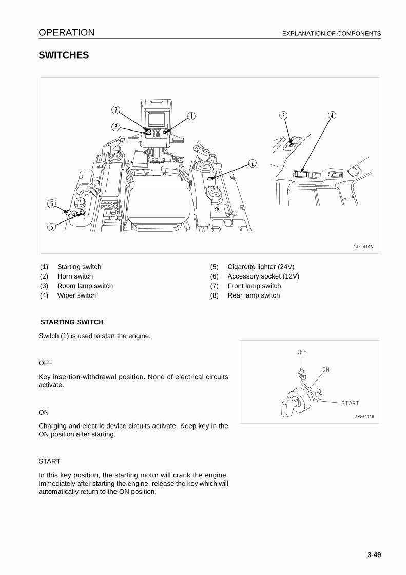
OPERATION EXPLANATION OF COMPONENTS
SWITCHES 3
STARTING SWITCH
Switch (1) is used to start the engine.
OFF
Key insertion-withdrawal position. None of electrical circuitsactivate.
ON
Charging and electric device circuits activate. Keep key in theON position after starting.
START
In this key position, the starting motor will crank the engine.Immediately after starting the engine, release the key which willautomatically return to the ON position.
(1) Starting switch (5) Cigarette lighter (24V)(2) Horn switch (6) Accessory socket (12V)(3) Room lamp switch (7) Front lamp switch(4) Wiper switch (8) Rear lamp switch
3-49
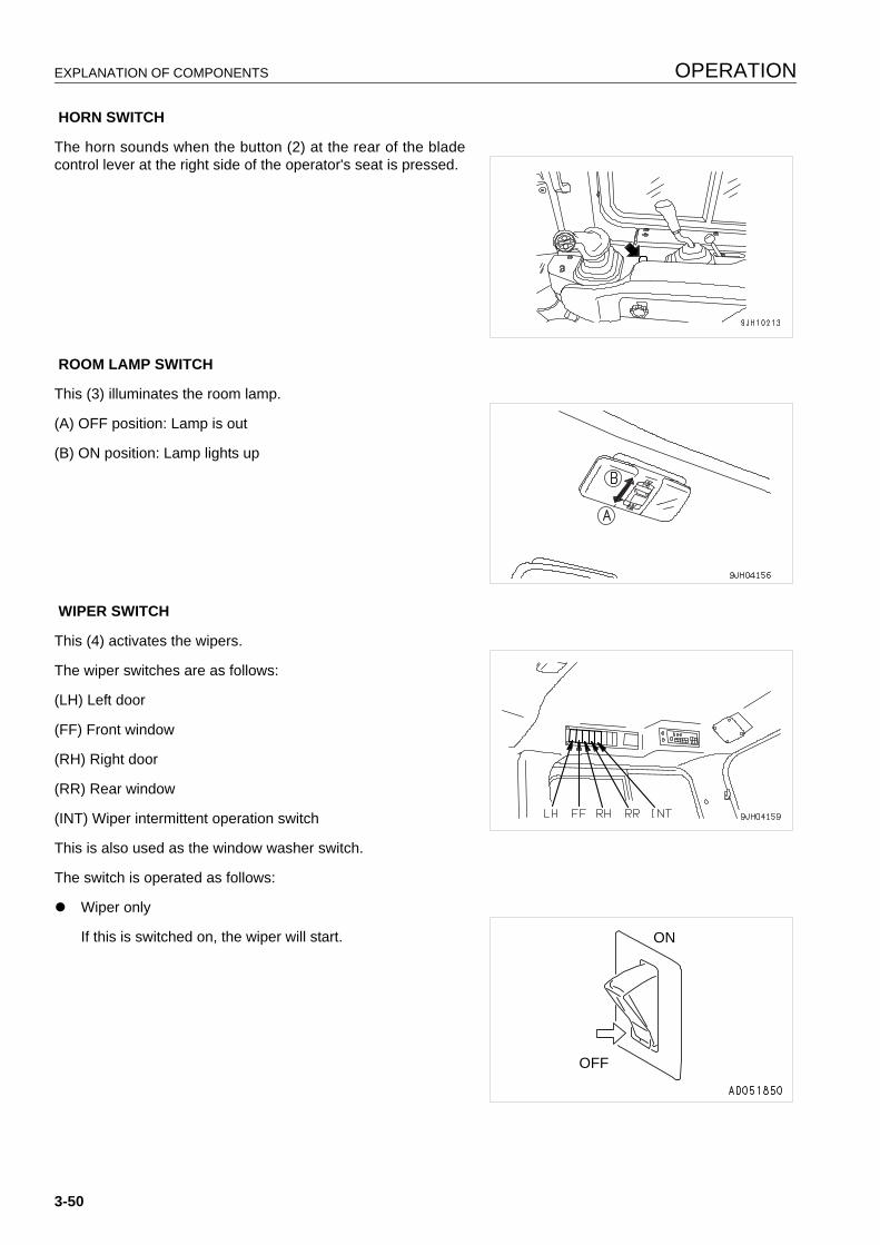
EXPLANATION OF COMPONENTS OPERATION
HORN SWITCH
The horn sounds when the button (2) at the rear of the bladecontrol lever at the right side of the operator's seat is pressed.
ROOM LAMP SWITCH
This (3) illuminates the room lamp.
(A) OFF position: Lamp is out
(B) ON position: Lamp lights up
WIPER SWITCH
This (4) activates the wipers.
The wiper switches are as follows:
(LH) Left door
(FF) Front window
(RH) Right door
(RR) Rear window
(INT) Wiper intermittent operation switch
This is also used as the window washer switch.
The switch is operated as follows:
q Wiper only
If this is switched on, the wiper will start. ON
OFF
3-50
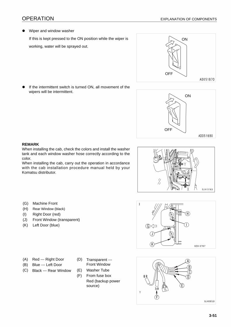
OPERATION EXPLANATION OF COMPONENTS
q Wiper and window washer
If this is kept pressed to the ON position while the wiper is
working, water will be sprayed out.
q If the intermittent switch is turned ON, all movement of thewipers will be intermittent.
REMARKWhen installing the cab, check the colors and install the washertank and each window washer hose correctly according to thecolor.When installing the cab, carry out the operation in accordancewith the cab installation procedure manual held by yourKomatsu distributor.
ON
OFF
ON
OFF
(G) Machine Front(H) Rear Window (black)(I) Right Door (red)(J) Front Window (transparent)(K) Left Door (blue)
(A) Red --- Right Door (D) Transparent --- Front Window(B) Blue --- Left Door
(C) Black --- Rear Window (E) Washer Tube(F) From fuse box
Red (backup power source)
3-51
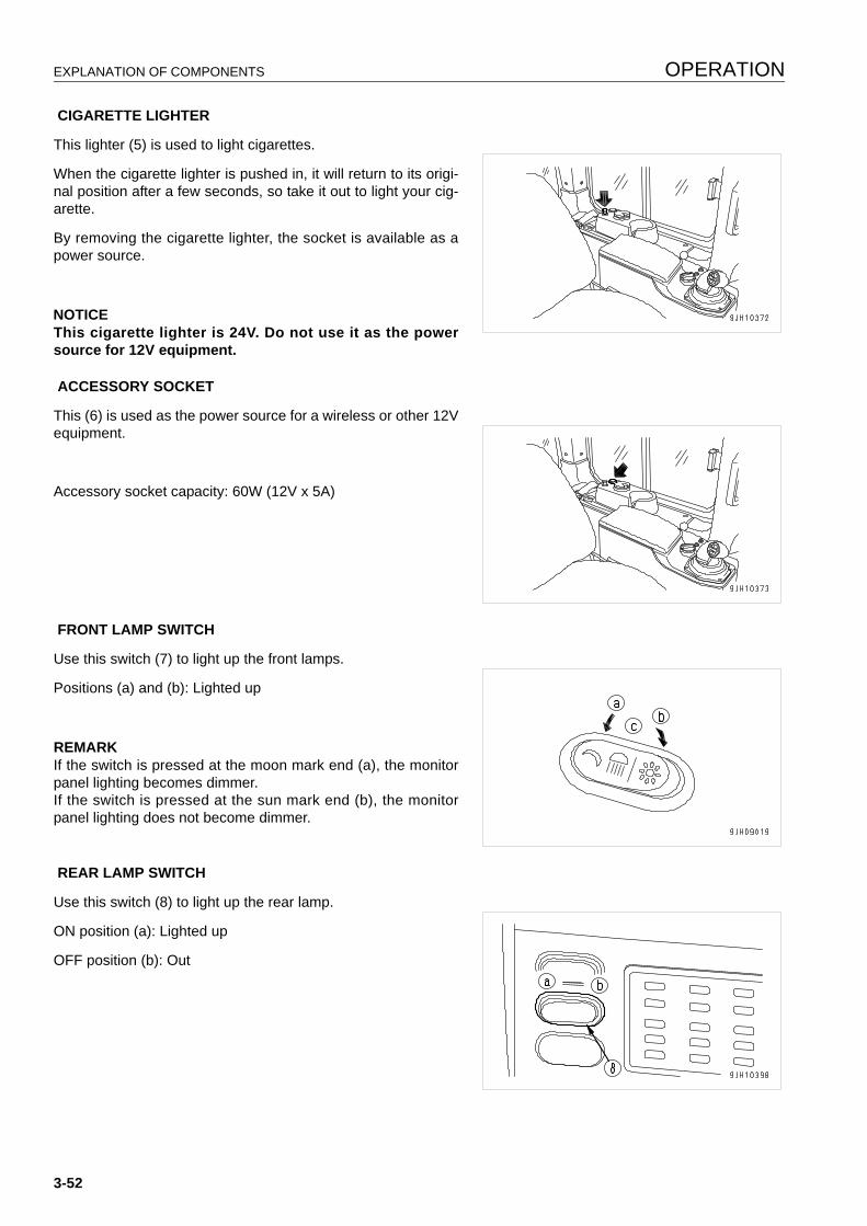
EXPLANATION OF COMPONENTS OPERATION
CIGARETTE LIGHTER
This lighter (5) is used to light cigarettes.
When the cigarette lighter is pushed in, it will return to its origi-nal position after a few seconds, so take it out to light your cig-arette.
By removing the cigarette lighter, the socket is available as apower source.
NOTICEThis cigarette lighter is 24V. Do not use it as the powersource for 12V equipment.
ACCESSORY SOCKET
This (6) is used as the power source for a wireless or other 12Vequipment.
Accessory socket capacity: 60W (12V x 5A)
FRONT LAMP SWITCH
Use this switch (7) to light up the front lamps.
Positions (a) and (b): Lighted up
REMARKIf the switch is pressed at the moon mark end (a), the monitorpanel lighting becomes dimmer.If the switch is pressed at the sun mark end (b), the monitorpanel lighting does not become dimmer.
REAR LAMP SWITCH
Use this switch (8) to light up the rear lamp.
ON position (a): Lighted up
OFF position (b): Out
3-52
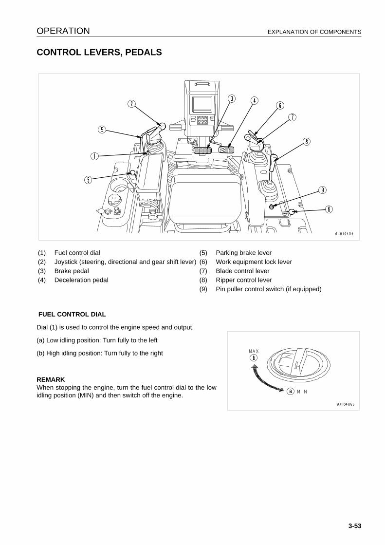
OPERATION EXPLANATION OF COMPONENTS
CONTROL LEVERS, PEDALS 3
FUEL CONTROL DIAL
Dial (1) is used to control the engine speed and output.
(a) Low idling position: Turn fully to the left
(b) High idling position: Turn fully to the right
REMARKWhen stopping the engine, turn the fuel control dial to the lowidling position (MIN) and then switch off the engine.
(1) Fuel control dial (5) Parking brake lever(2) Joystick (steering, directional and gear shift lever) (6) Work equipment lock lever(3) Brake pedal (7) Blade control lever(4) Deceleration pedal (8) Ripper control lever
(9) Pin puller control switch (if equipped)
3-53
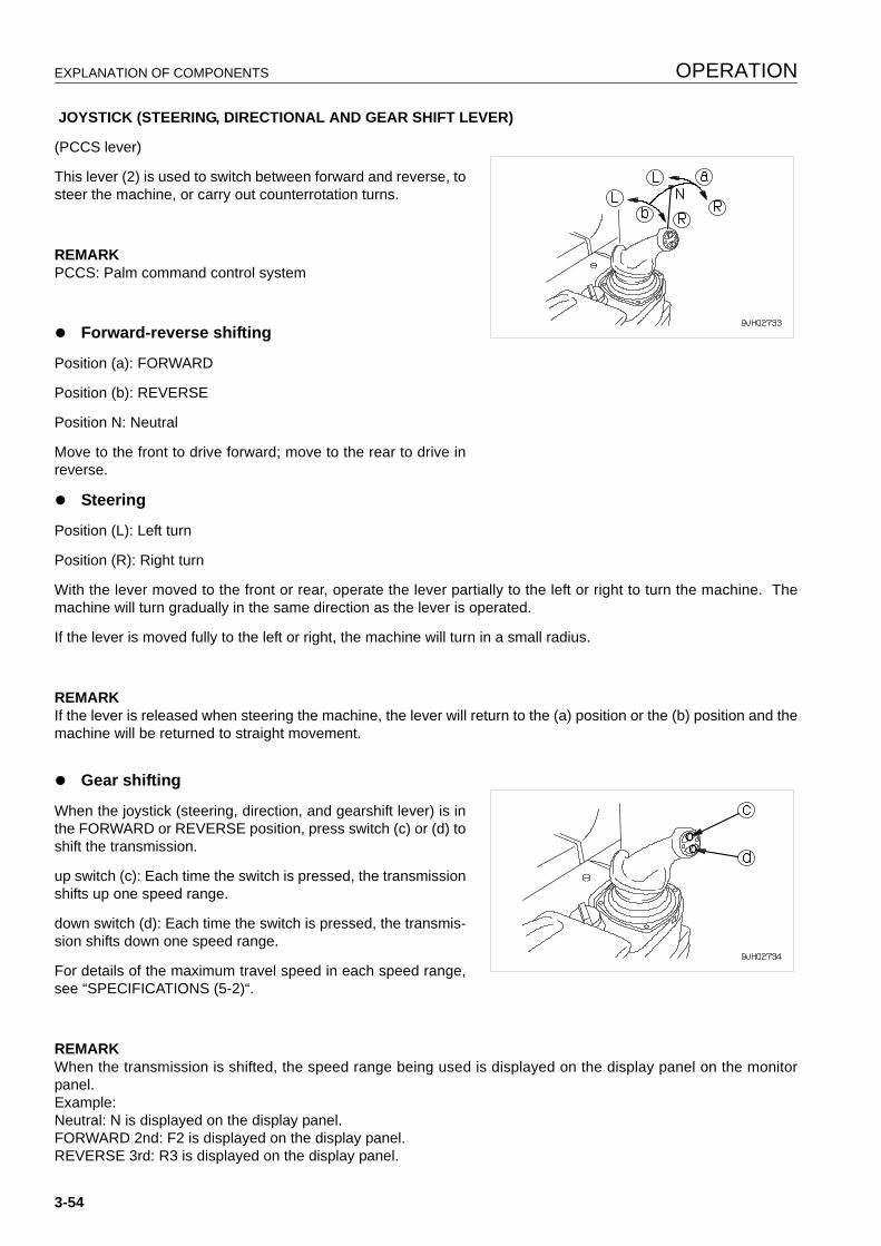
EXPLANATION OF COMPONENTS OPERATION
JOYSTICK (STEERING, DIRECTIONAL AND GEAR SHIFT LEVER)
(PCCS lever)
This lever (2) is used to switch between forward and reverse, tosteer the machine, or carry out counterrotation turns.
REMARKPCCS: Palm command control system
q Forward-reverse shifting
Position (a): FORWARD
Position (b): REVERSE
Position N: Neutral
Move to the front to drive forward; move to the rear to drive inreverse.
q Steering
Position (L): Left turn
Position (R): Right turn
With the lever moved to the front or rear, operate the lever partially to the left or right to turn the machine. Themachine will turn gradually in the same direction as the lever is operated.
If the lever is moved fully to the left or right, the machine will turn in a small radius.
REMARKIf the lever is released when steering the machine, the lever will return to the (a) position or the (b) position and themachine will be returned to straight movement.
q Gear shifting
When the joystick (steering, direction, and gearshift lever) is inthe FORWARD or REVERSE position, press switch (c) or (d) toshift the transmission.
up switch (c): Each time the switch is pressed, the transmissionshifts up one speed range.
down switch (d): Each time the switch is pressed, the transmis-sion shifts down one speed range.
For details of the maximum travel speed in each speed range,see “SPECIFICATIONS (5-2)“.
REMARKWhen the transmission is shifted, the speed range being used is displayed on the display panel on the monitorpanel.Example:Neutral: N is displayed on the display panel.FORWARD 2nd: F2 is displayed on the display panel.REVERSE 3rd: R3 is displayed on the display panel.
3-54
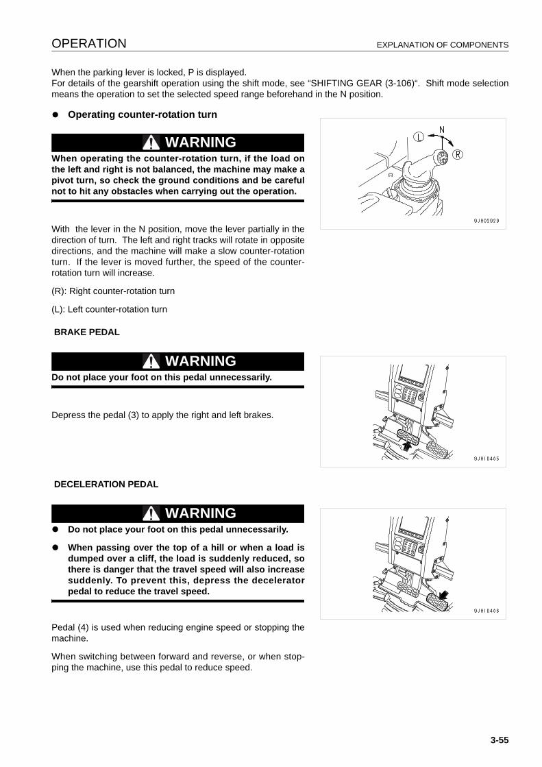
OPERATION EXPLANATION OF COMPONENTS
When the parking lever is locked, P is displayed.For details of the gearshift operation using the shift mode, see “SHIFTING GEAR (3-106)“. Shift mode selectionmeans the operation to set the selected speed range beforehand in the N position.
q Operating counter-rotation turn
WARNINGWhen operating the counter-rotation turn, if the load onthe left and right is not balanced, the machine may make apivot turn, so check the ground conditions and be carefulnot to hit any obstacles when carrying out the operation.
With the lever in the N position, move the lever partially in thedirection of turn. The left and right tracks will rotate in oppositedirections, and the machine will make a slow counter-rotationturn. If the lever is moved further, the speed of the counter-rotation turn will increase.
(R): Right counter-rotation turn
(L): Left counter-rotation turn
BRAKE PEDAL
WARNINGDo not place your foot on this pedal unnecessarily.
Depress the pedal (3) to apply the right and left brakes.
DECELERATION PEDAL
WARNINGq Do not place your foot on this pedal unnecessarily.
q When passing over the top of a hill or when a load isdumped over a cliff, the load is suddenly reduced, sothere is danger that the travel speed will also increasesuddenly. To prevent this, depress the deceleratorpedal to reduce the travel speed.
Pedal (4) is used when reducing engine speed or stopping themachine.
When switching between forward and reverse, or when stop-ping the machine, use this pedal to reduce speed.
3-55
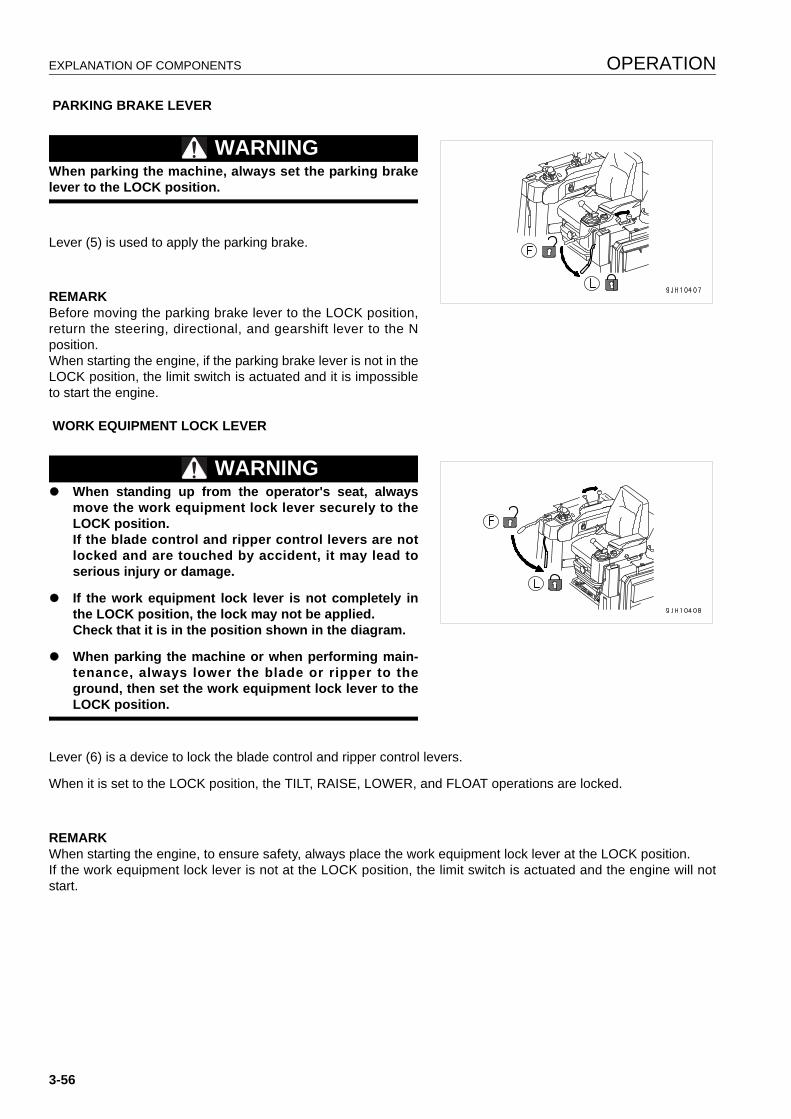
EXPLANATION OF COMPONENTS OPERATION
PARKING BRAKE LEVER
WARNINGWhen parking the machine, always set the parking brakelever to the LOCK position.
Lever (5) is used to apply the parking brake.
REMARKBefore moving the parking brake lever to the LOCK position,return the steering, directional, and gearshift lever to the Nposition.When starting the engine, if the parking brake lever is not in theLOCK position, the limit switch is actuated and it is impossibleto start the engine.
WORK EQUIPMENT LOCK LEVER
WARNINGq When standing up from the operator's seat, always
move the work equipment lock lever securely to theLOCK position.If the blade control and ripper control levers are notlocked and are touched by accident, it may lead toserious injury or damage.
q If the work equipment lock lever is not completely inthe LOCK position, the lock may not be applied.Check that it is in the position shown in the diagram.
q When parking the machine or when performing main-tenance, always lower the blade or ripper to theground, then set the work equipment lock lever to theLOCK position.
Lever (6) is a device to lock the blade control and ripper control levers.
When it is set to the LOCK position, the TILT, RAISE, LOWER, and FLOAT operations are locked.
REMARKWhen starting the engine, to ensure safety, always place the work equipment lock lever at the LOCK position.If the work equipment lock lever is not at the LOCK position, the limit switch is actuated and the engine will notstart.
3-56

OPERATION EXPLANATION OF COMPONENTS
BLADE CONTROL LEVER
Single tiltdozer
Lever (7) is used to raise or tilt the blade.
q Lifting control
(a) RAISE:
(b) HOLD: Blade is stopped and held in position.
(c) LOWER:
(d) FLOAT button: Blade moves freely under external force.
REMARKIf the lever is not operated fully in the LOWER direction, it willnot enter FLOAT. After operating the FLOAT mode switch onthe monitor panel, keep the FLOAT button on the blade controllever pressed and operate the lever fully to the LOWER posi-tion. It will enter FLOAT.When using the FLOAT mode, the lever is not held in position.
q TILT OPERATION
(A) RIGHT TILT
(B) LEFT TILT
3-57
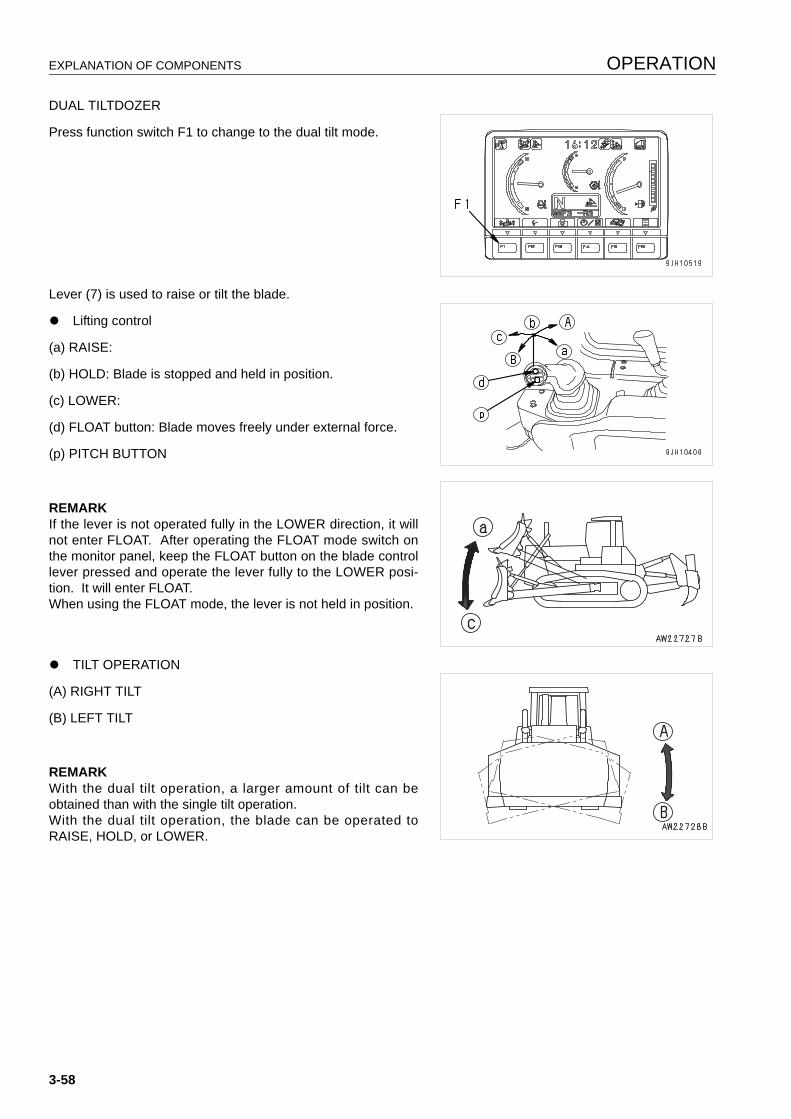
EXPLANATION OF COMPONENTS OPERATION
DUAL TILTDOZER
Press function switch F1 to change to the dual tilt mode.
Lever (7) is used to raise or tilt the blade.
q Lifting control
(a) RAISE:
(b) HOLD: Blade is stopped and held in position.
(c) LOWER:
(d) FLOAT button: Blade moves freely under external force.
(p) PITCH BUTTON
REMARKIf the lever is not operated fully in the LOWER direction, it willnot enter FLOAT. After operating the FLOAT mode switch onthe monitor panel, keep the FLOAT button on the blade controllever pressed and operate the lever fully to the LOWER posi-tion. It will enter FLOAT.When using the FLOAT mode, the lever is not held in position.
q TILT OPERATION
(A) RIGHT TILT
(B) LEFT TILT
REMARKWith the dual tilt operation, a larger amount of tilt can beobtained than with the single tilt operation.With the dual tilt operation, the blade can be operated toRAISE, HOLD, or LOWER.
3-58
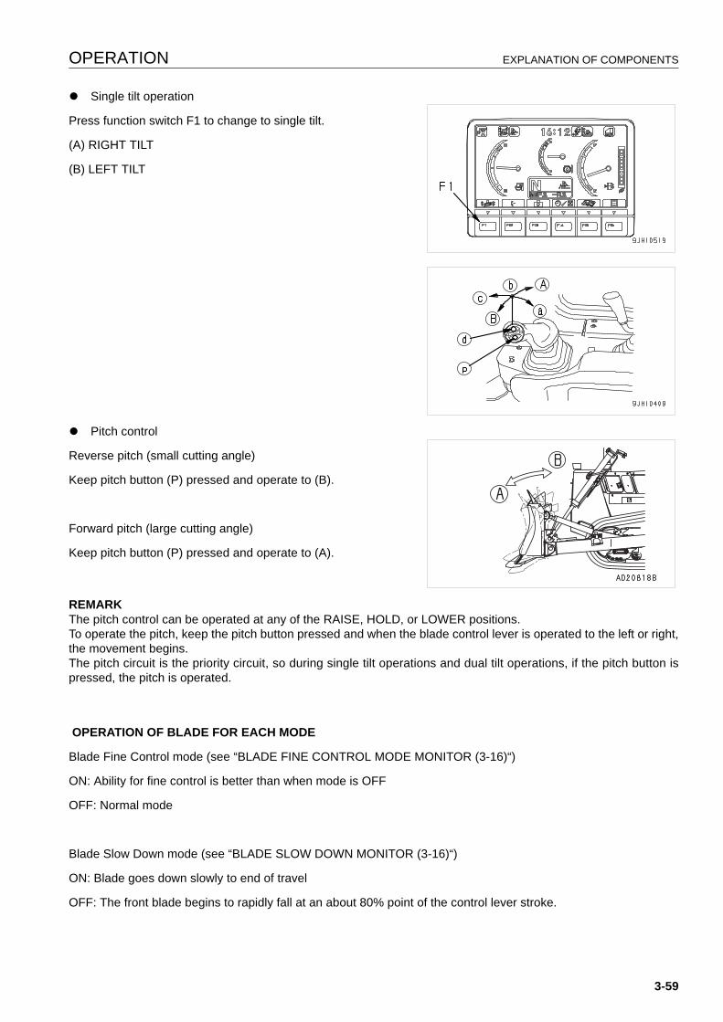
OPERATION EXPLANATION OF COMPONENTS
q Single tilt operation
Press function switch F1 to change to single tilt.
(A) RIGHT TILT
(B) LEFT TILT
q Pitch control
Reverse pitch (small cutting angle)
Keep pitch button (P) pressed and operate to (B).
Forward pitch (large cutting angle)
Keep pitch button (P) pressed and operate to (A).
REMARKThe pitch control can be operated at any of the RAISE, HOLD, or LOWER positions.To operate the pitch, keep the pitch button pressed and when the blade control lever is operated to the left or right,the movement begins.The pitch circuit is the priority circuit, so during single tilt operations and dual tilt operations, if the pitch button ispressed, the pitch is operated.
OPERATION OF BLADE FOR EACH MODE
Blade Fine Control mode (see “BLADE FINE CONTROL MODE MONITOR (3-16)“)
ON: Ability for fine control is better than when mode is OFF
OFF: Normal mode
Blade Slow Down mode (see “BLADE SLOW DOWN MONITOR (3-16)“)
ON: Blade goes down slowly to end of travel
OFF: The front blade begins to rapidly fall at an about 80% point of the control lever stroke.
3-59
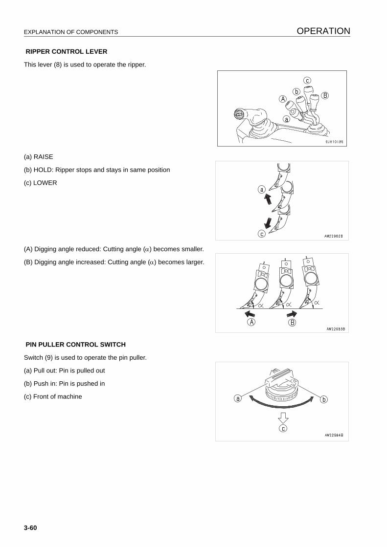
EXPLANATION OF COMPONENTS OPERATION
RIPPER CONTROL LEVER
This lever (8) is used to operate the ripper.
(a) RAISE
(b) HOLD: Ripper stops and stays in same position
(c) LOWER
(A) Digging angle reduced: Cutting angle (α) becomes smaller.
(B) Digging angle increased: Cutting angle (α) becomes larger.
PIN PULLER CONTROL SWITCH
Switch (9) is used to operate the pin puller.
(a) Pull out: Pin is pulled out
(b) Push in: Pin is pushed in
(c) Front of machine
3-60
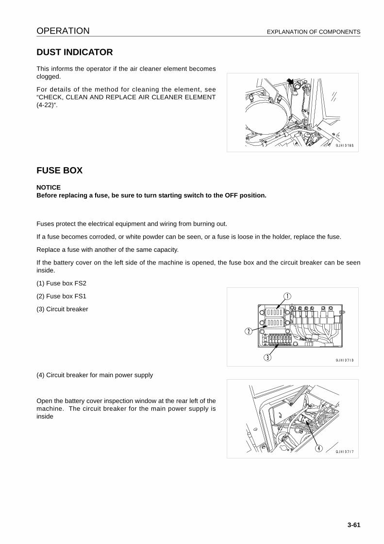
OPERATION EXPLANATION OF COMPONENTS
DUST INDICATOR 3
This informs the operator if the air cleaner element becomesclogged.
For details of the method for cleaning the element, see“CHECK, CLEAN AND REPLACE AIR CLEANER ELEMENT(4-22)“.
FUSE BOX 3
NOTICEBefore replacing a fuse, be sure to turn starting switch to the OFF position.
Fuses protect the electrical equipment and wiring from burning out.
If a fuse becomes corroded, or white powder can be seen, or a fuse is loose in the holder, replace the fuse.
Replace a fuse with another of the same capacity.
If the battery cover on the left side of the machine is opened, the fuse box and the circuit breaker can be seeninside.
(1) Fuse box FS2
(2) Fuse box FS1
(3) Circuit breaker
(4) Circuit breaker for main power supply
Open the battery cover inspection window at the rear left of themachine. The circuit breaker for the main power supply isinside
3-61
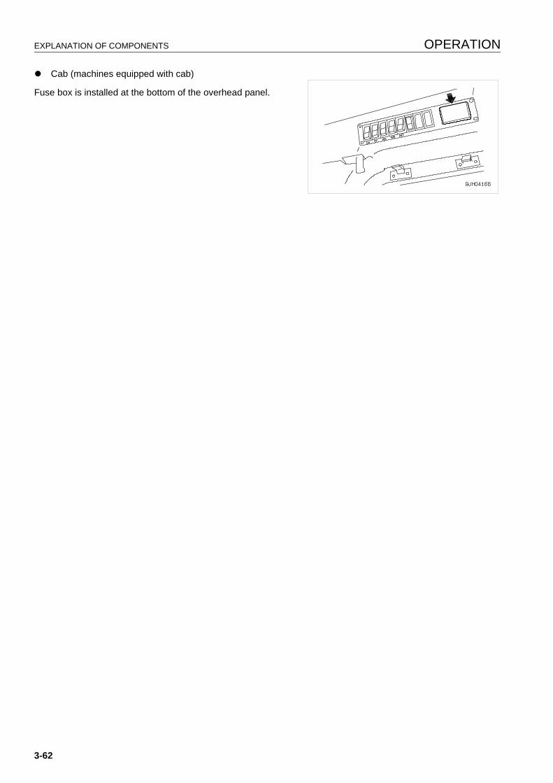
EXPLANATION OF COMPONENTS OPERATION
q Cab (machines equipped with cab)
Fuse box is installed at the bottom of the overhead panel.
3-62

OPERATION EXPLANATION OF COMPONENTS
CIRCUIT BREAKER 3
q If the engine does not start up when the starting switch isturned to the ON position, open up the battery cover andcheck the battery.
q If excessive current flows through the circuit breaker, it cutsoff the electric circuit to prevent damage to the electricalcomponents and wiring.
q To restore the electric circuit after it has been cut off, pushin reset button (3). (This springs out when the circuit is cutoff.)
If the electric circuit is normal, reset button (3) will staypushed in. If it comes out immediately when it is pushedin, the electric circuit must be checked.
REMARKThe circuit breaker is a device installed in electric circuits where a large current flows. It is installed to protect theelectric circuit. It protects the electric components and wiring from damage caused by an abnormal current in thesame way as a normal fuse. After repairing and restoring the location of the abnormality, there is no need toreplace the breaker. It can be used again.
CIRCUIT BREAKER FOR MAIN POWER SUPPLY 3
q If the starting motor is not actuated when the starting motoris turned ON, open the battery cover inspection window atthe rear left of the machine and inspect circuit breakers (A)and (B).
(A) and (B) also act as the reset button.
q If there is a surge of current, the circuit breaker shuts offthe circuit to protect the electrical components and wiringfrom damage.
q Turn the starting switch to the OFF position and reset the circuit breaker.
q When resetting the electrical circuit after it has been shut off, press the reset button 5 to 10 minutes after thecircuit has been shut off. When the electrical circuit has been shut off, the operation of the reset button isheavier than when the circuit is normal. The height of the reset button is the same, regardless of whether thecircuit has been shut off or has been reset, so make note of the effort of the reset button when resetting the cir-cuit.
q Do not keep the circuit breaker reset button longer than necessary.
No Fusecapasity Circuit
(1) 20A Permanently ON power source(2) 20A Starting switch(3) 20A Rear lamp(4) 20A Front lamp(5) 20A Air conditioner(6) 20A Work equipment controller(7) 20A Power train controller(8) 20A Option
3-63
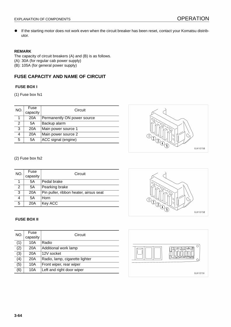
EXPLANATION OF COMPONENTS OPERATION
q If the starting motor does not work even when the circuit breaker has been reset, contact your Komatsu distrib-utor.
REMARKThe capacity of circuit breakers (A) and (B) is as follows.(A): 30A (for regular cab power supply)(B): 105A (for general power supply)
FUSE CAPACITY AND NAME OF CIRCUIT 3
FUSE BOX I
(1) Fuse box fs1
(2) Fuse box fs2
FUSE BOX II
NO. Fusecapacity Circuit
1 20A Permanently ON power source2 5A Backup alarm3 20A Main power source 14 20A Main power source 25 5A ACC signal (engine)
NO. Fusecapasity Circuit
1 5A Pedal brake2 5A Pearking brake3 20A Pin puller, ribbon heater, airsus seat4 5A Horn5 20A Key ACC
NO. Fusecapasity Circuit
(1) 10A Radio(2) 20A Additional work lamp(3) 20A 12V socket(4) 20A Radio, lamp, cigarette lighter(5) 10A Front wiper, rear wiper(6) 10A Left and right door wiper
3-64
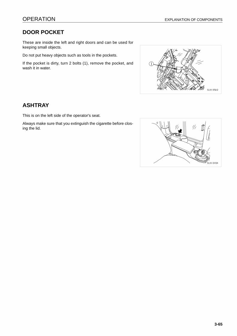
OPERATION EXPLANATION OF COMPONENTS
DOOR POCKET 3
These are inside the left and right doors and can be used forkeeping small objects.
Do not put heavy objects such as tools in the pockets.
If the pocket is dirty, turn 2 bolts (1), remove the pocket, andwash it in water.
ASHTRAY 3
This is on the left side of the operator's seat.
Always make sure that you extinguish the cigarette before clos-ing the lid.
3-65
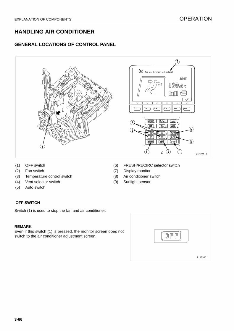
EXPLANATION OF COMPONENTS OPERATION
HANDLING AIR CONDITIONER 3
GENERAL LOCATIONS OF CONTROL PANEL 3
OFF SWITCH
Switch (1) is used to stop the fan and air conditioner.
REMARKEven if this switch (1) is pressed, the monitor screen does notswitch to the air conditioner adjustment screen.
(1) OFF switch (6) FRESH/RECIRC selector switch(2) Fan switch (7) Display monitor(3) Temperature control switch (8) Air conditioner switch(4) Vent selector switch (9) Sunlight sensor(5) Auto switch
3-66
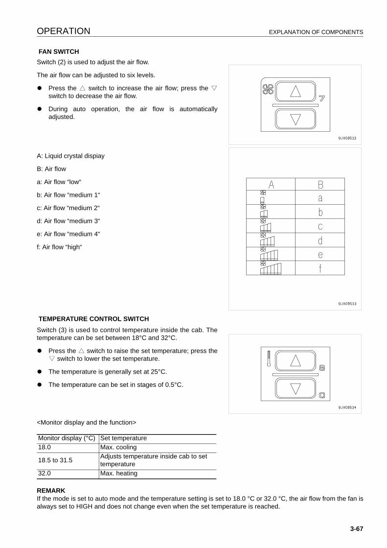
OPERATION EXPLANATION OF COMPONENTS
FAN SWITCHSwitch (2) is used to adjust the air flow.
The air flow can be adjusted to six levels.
q Press the E switch to increase the air flow; press the Rswitch to decrease the air flow.
q During auto operation, the air flow is automaticallyadjusted.
A: Liquid crystal dispiay
B: Air flow
a: Air flow “low“
b: Air flow “medium 1“
c: Air flow “medium 2“
d: Air flow “medium 3“
e: Air flow “medium 4“
f: Air flow “high“
TEMPERATURE CONTROL SWITCHSwitch (3) is used to control temperature inside the cab. Thetemperature can be set between 18°C and 32°C.
q Press the E switch to raise the set temperature; press theR switch to lower the set temperature.
q The temperature is generally set at 25°C.
q The temperature can be set in stages of 0.5°C.
<Monitor display and the function>
REMARKIf the mode is set to auto mode and the temperature setting is set to 18.0 °C or 32.0 °C, the air flow from the fan isalways set to HIGH and does not change even when the set temperature is reached.
Monitor display (°C) Set temperature18.0 Max. cooling
18.5 to 31.5 Adjusts temperature inside cab to set temperature
32.0 Max. heating
3-67
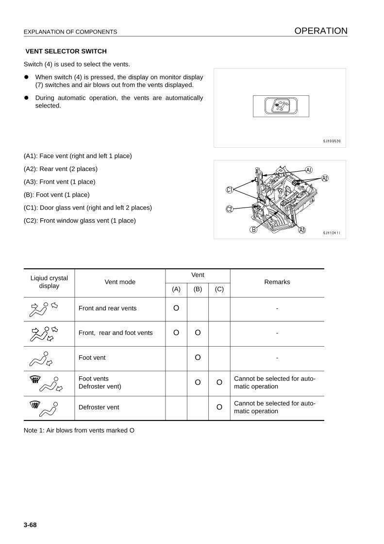
EXPLANATION OF COMPONENTS OPERATION
VENT SELECTOR SWITCH
Switch (4) is used to select the vents.
q When switch (4) is pressed, the display on monitor display(7) switches and air blows out from the vents displayed.
q During automatic operation, the vents are automaticallyselected.
(A1): Face vent (right and left 1 place)
(A2): Rear vent (2 places)
(A3): Front vent (1 place)
(B): Foot vent (1 place)
(C1): Door glass vent (right and left 2 places)
(C2): Front window glass vent (1 place)
Note 1: Air blows from vents marked O
Liqiud crystaldisplay Vent mode
VentRemarks
(A) (B) (C)
Front and rear vents O -
Front, rear and foot vents O O -
Foot vent O -
Foot vents Defroster vent) O O Cannot be selected for auto-
matic operation
Defroster vent O Cannot be selected for auto-matic operation
3-68
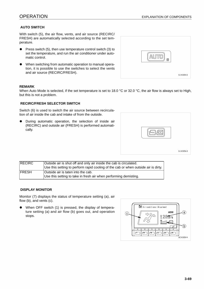
OPERATION EXPLANATION OF COMPONENTS
AUTO SWITCH
With switch (5), the air flow, vents, and air source (RECIRC/FRESH) are automatically selected according to the set tem-perature.
q Press switch (5), then use temperature control switch (3) toset the temperature, and run the air conditioner under auto-matic control.
q When switching from automatic operation to manual opera-tion, it is possible to use the switches to select the ventsand air source (RECIRC/FRESH).
REMARKWhen Auto Mode is selected, if the set temperature is set to 18.0 °C or 32.0 °C, the air flow is always set to High,but this is not a problem.
RECIRC/FRESH SELECTOR SWITCH
Switch (6) is used to switch the air source between recircula-tion of air inside the cab and intake of from the outside.
q During automatic operation, the selection of inside air(RECIRC) and outside air (FRESH) is performed automati-cally.
DISPLAY MONITOR
Monitor (7) displays the status of temperature setting (a), airflow (b), and vents (c).
q When OFF switch (1) is pressed, the display of tempera-ture setting (a) and air flow (b) goes out, and operationstops.
RECIRC Outside air is shut off and only air inside the cab is circulated.Use this setting to perform rapid cooling of the cab or when outside air is dirty.
FRESH Outside air is taten into the cab.Use this setting to take in fresh air when performing demisting.
3-69
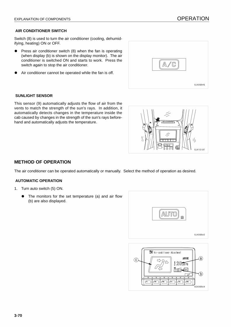
EXPLANATION OF COMPONENTS OPERATION
AIR CONDITIONER SWITCH
Switch (8) is used to turn the air conditioner (cooling, dehumid-ifying, heating) ON or OFF.
q Press air conditioner switch (8) when the fan is operating(when display (b) is shown on the display monitor). The airconditioner is switched ON and starts to work. Press theswitch again to stop the air conditioner.
q Air conditioner cannot be operated while the fan is off.
SUNLIGHT SENSOR
This sensor (9) automatically adjusts the flow of air from thevents to match the strength of the sun's rays. In addition, itautomatically detects changes in the temperature inside thecab caused by changes in the strength of the sun's rays before-hand and automatically adjusts the temperature.
METHOD OF OPERATION 3
The air conditioner can be operated automatically or manually. Select the method of operation as desired.
AUTOMATIC OPERATION
1. Turn auto switch (5) ON.
q The monitors for the set temperature (a) and air flow(b) are also displayed.
3-70
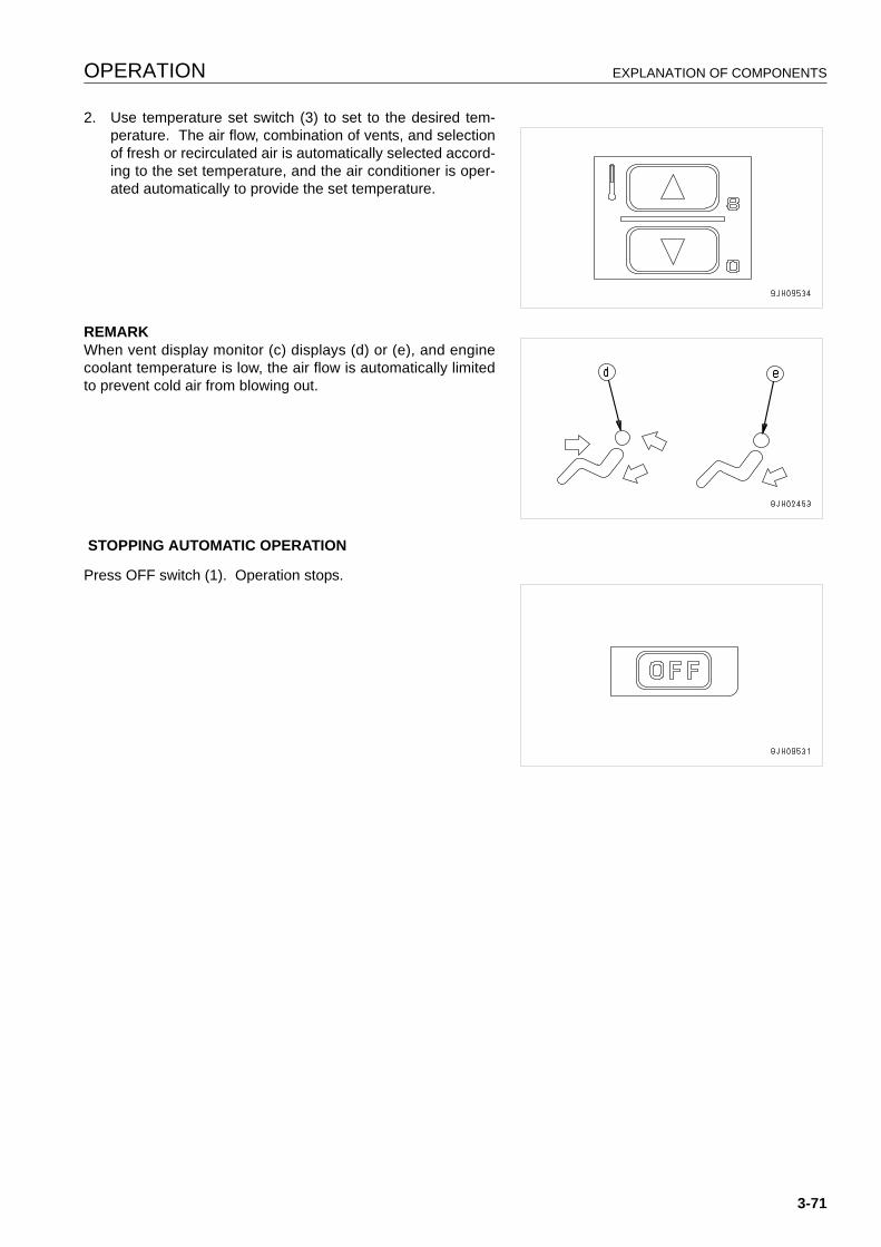
OPERATION EXPLANATION OF COMPONENTS
2. Use temperature set switch (3) to set to the desired tem-perature. The air flow, combination of vents, and selectionof fresh or recirculated air is automatically selected accord-ing to the set temperature, and the air conditioner is oper-ated automatically to provide the set temperature.
REMARKWhen vent display monitor (c) displays (d) or (e), and enginecoolant temperature is low, the air flow is automatically limitedto prevent cold air from blowing out.
STOPPING AUTOMATIC OPERATION
Press OFF switch (1). Operation stops.
3-71
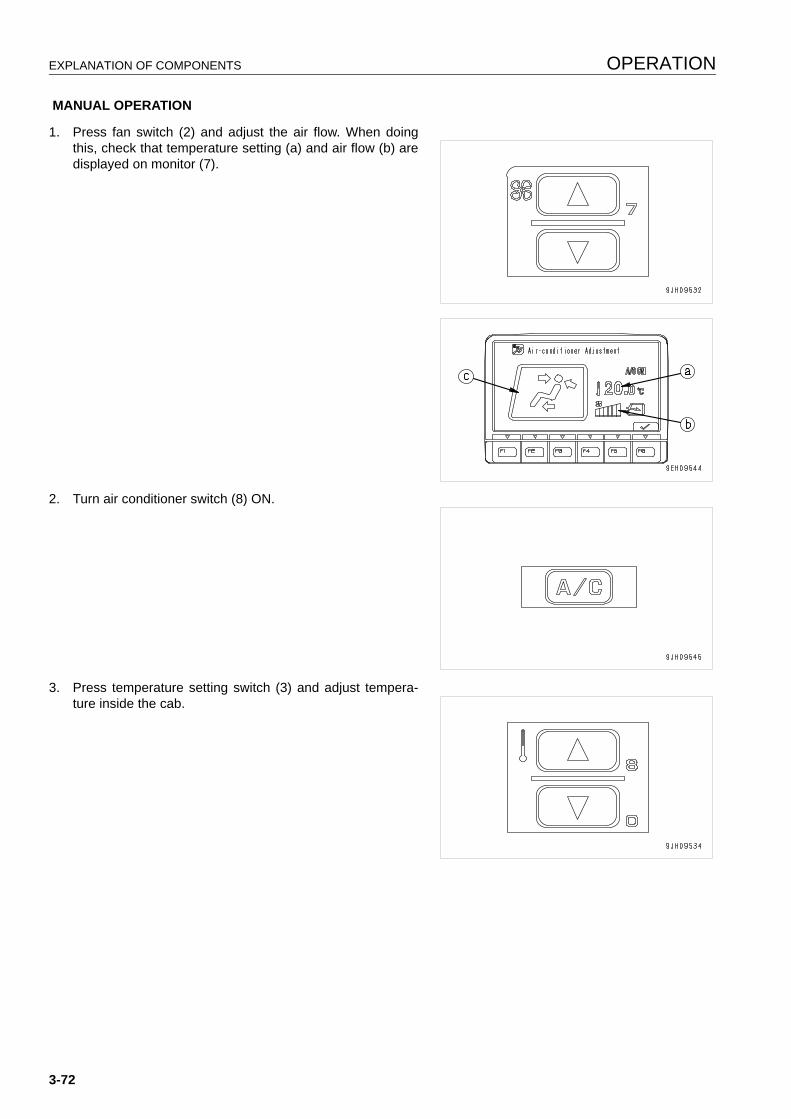
EXPLANATION OF COMPONENTS OPERATION
MANUAL OPERATION
1. Press fan switch (2) and adjust the air flow. When doingthis, check that temperature setting (a) and air flow (b) aredisplayed on monitor (7).
2. Turn air conditioner switch (8) ON.
3. Press temperature setting switch (3) and adjust tempera-ture inside the cab.
3-72
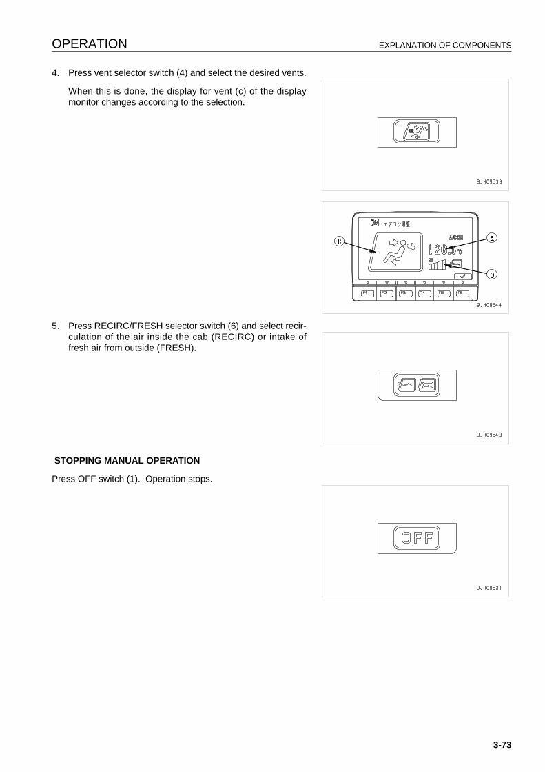
OPERATION EXPLANATION OF COMPONENTS
4. Press vent selector switch (4) and select the desired vents.
When this is done, the display for vent (c) of the displaymonitor changes according to the selection.
5. Press RECIRC/FRESH selector switch (6) and select recir-culation of the air inside the cab (RECIRC) or intake offresh air from outside (FRESH).
STOPPING MANUAL OPERATION
Press OFF switch (1). Operation stops.
3-73
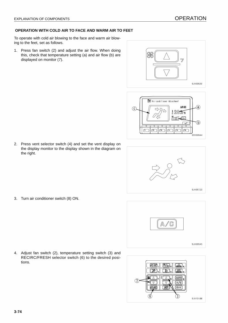
EXPLANATION OF COMPONENTS OPERATION
OPERATION WITH COLD AIR TO FACE AND WARM AIR TO FEET
To operate with cold air blowing to the face and warm air blow-ing to the feet, set as follows.
1. Press fan switch (2) and adjust the air flow. When doingthis, check that temperature setting (a) and air flow (b) aredisplayed on monitor (7).
2. Press vent selector switch (4) and set the vent display onthe display monitor to the display shown in the diagram onthe right.
3. Turn air conditioner switch (8) ON.
4. Adjust fan switch (2), temperature setting switch (3) andRECIRC/FRESH selector switch (6) to the desired posi-tions.
3-74
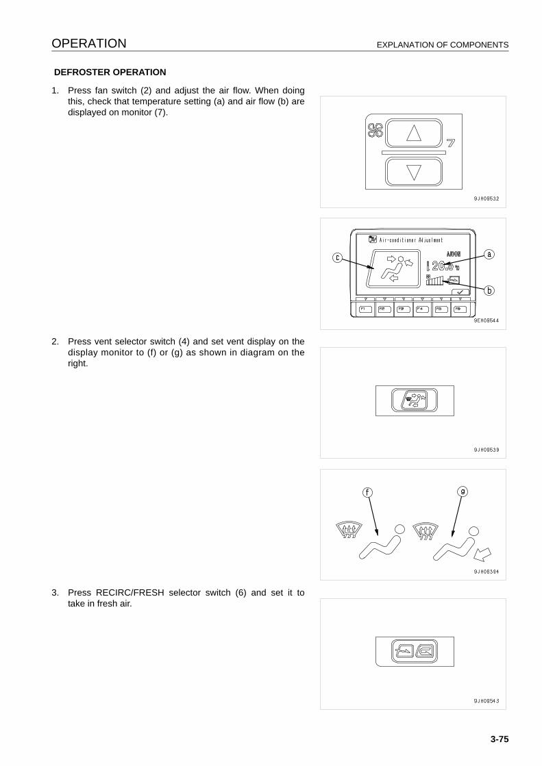
OPERATION EXPLANATION OF COMPONENTS
DEFROSTER OPERATION
1. Press fan switch (2) and adjust the air flow. When doingthis, check that temperature setting (a) and air flow (b) aredisplayed on monitor (7).
2. Press vent selector switch (4) and set vent display on thedisplay monitor to (f) or (g) as shown in diagram on theright.
3. Press RECIRC/FRESH selector switch (6) and set it totake in fresh air.
3-75
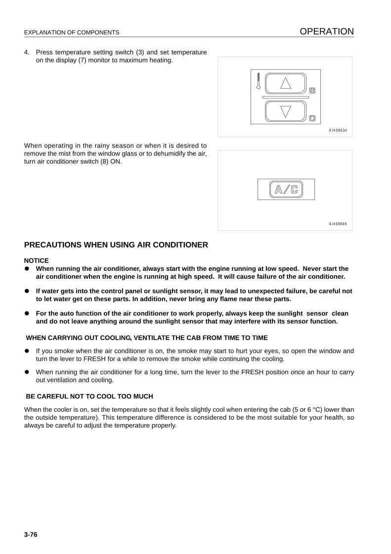
EXPLANATION OF COMPONENTS OPERATION
4. Press temperature setting switch (3) and set temperatureon the display (7) monitor to maximum heating.
When operating in the rainy season or when it is desired toremove the mist from the window glass or to dehumidify the air,turn air conditioner switch (8) ON.
PRECAUTIONS WHEN USING AIR CONDITIONER 3
NOTICEq When running the air conditioner, always start with the engine running at low speed. Never start the
air conditioner when the engine is running at high speed. It will cause failure of the air conditioner.
q If water gets into the control panel or sunlight sensor, it may lead to unexpected failure, be careful not to let water get on these parts. In addition, never bring any flame near these parts.
q For the auto function of the air conditioner to work properly, always keep the sunlight sensor clean and do not leave anything around the sunlight sensor that may interfere with its sensor function.
WHEN CARRYING OUT COOLING, VENTILATE THE CAB FROM TIME TO TIME
q If you smoke when the air conditioner is on, the smoke may start to hurt your eyes, so open the window andturn the lever to FRESH for a while to remove the smoke while continuing the cooling.
q When running the air conditioner for a long time, turn the lever to the FRESH position once an hour to carryout ventilation and cooling.
BE CAREFUL NOT TO COOL TOO MUCH
When the cooler is on, set the temperature so that it feels slightly cool when entering the cab (5 or 6 °C) lower thanthe outside temperature). This temperature difference is considered to be the most suitable for your health, soalways be careful to adjust the temperature properly.
3-76
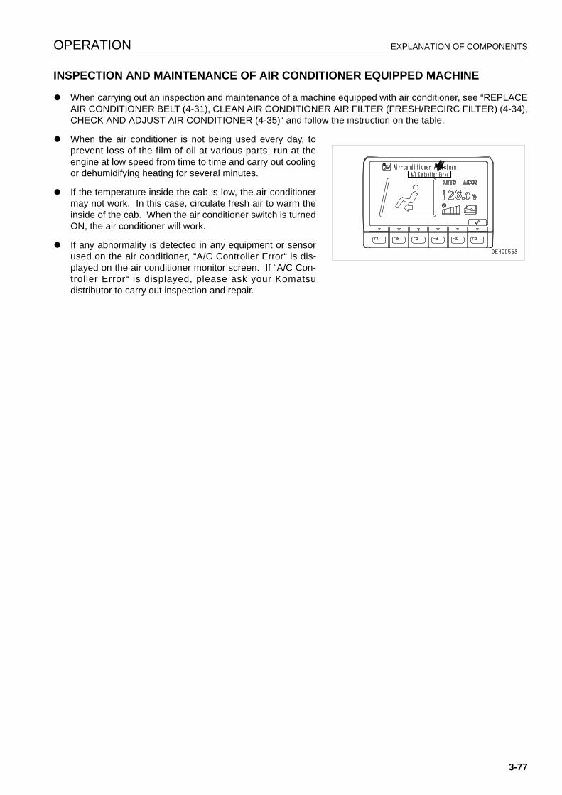
OPERATION EXPLANATION OF COMPONENTS
INSPECTION AND MAINTENANCE OF AIR CONDITIONER EQUIPPED MACHINE 3
q When carrying out an inspection and maintenance of a machine equipped with air conditioner, see “REPLACEAIR CONDITIONER BELT (4-31), CLEAN AIR CONDITIONER AIR FILTER (FRESH/RECIRC FILTER) (4-34),CHECK AND ADJUST AIR CONDITIONER (4-35)“ and follow the instruction on the table.
q When the air conditioner is not being used every day, toprevent loss of the film of oil at various parts, run at theengine at low speed from time to time and carry out coolingor dehumidifying heating for several minutes.
q If the temperature inside the cab is low, the air conditionermay not work. In this case, circulate fresh air to warm theinside of the cab. When the air conditioner switch is turnedON, the air conditioner will work.
q If any abnormality is detected in any equipment or sensorused on the air conditioner, “A/C Controller Error“ is dis-played on the air conditioner monitor screen. If “A/C Con-troller Error“ is displayed, please ask your Komatsudistributor to carry out inspection and repair.
3-77
OPERATION OPERATION
OPERATION 3
CHECK BEFORE STARTING ENGINE, ADJUST 3
WALK-AROUND CHECK 3
Before starting the engine, look around and under the machine to check for loose nuts and bolts, or leakage of oil,fuel, or coolant, and check condition of the work equipment and hydraulic system. Also check for loose wiring andplay, and accumulation of dust at places with high temperatures.
WARNINGq Leakage of oil or fuel, or accumulation of flammable material around high temperature parts, such as
the engine muffler or turbocharger, may cause fire.Check carefully, and if any abnormality is found, repair it or contact your Komatsu distributor.
q Do not get on or off the machine from the rear. Using this position is dangerous because it is easy toslip and you cannot be seen from the operator's compartment. Always use the handrail and step at theside when getting on or off the machine.
If the machine is at an angle, make it level before checking.
Before starting the engine, look around the machine and under the machine to check for loose nut or bolts, or leak-age of oil, fuel, or coolant, and check the condition of the work equipment and hydraulic system. Check also forloose wiring, play, and collection of dust at places which reach high temperatures.
Always carry out the items in this section before starting the engine each day.
1. Check for damage, wear, play in work equipment, cylinders, linkage, hoses
Check that there are no cracks, excessive wear, or play in the work equipment, cylinders, linkage, or hoses. If anyabnormality is found, repair it.
2. Remove dirt and dust from around engine, battery radiator.
Check if there is any dirt or dust accumulated around the engine or radiator. Check also if there is any flammablematerial (dead leaves, twigs, grass, etc.) accumulated around the battery or high temperature engine parts, suchas the engine muffler or turbocharger. Remove all such dirt or flammable material.
3. Check for leakage of water or oil around engine
Check that there is no oil leakage from the engine or coolant leakage from the cooling system. If any problem isfound, repair it.
4. Check for oil leakage from power train case, final drive case, hydraulic tank, hose, joint.
Check that there is no oil leakage. If any problem is found, repair the place where the oil is leaking.
Check for leakage of oil from the undercover. Check the ground for traces of oil leakage.
3-78
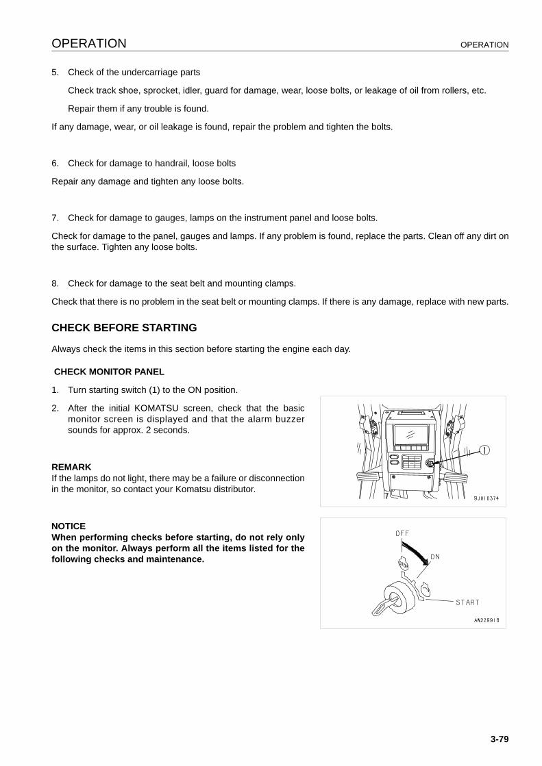
OPERATION OPERATION
5. Check of the undercarriage parts
Check track shoe, sprocket, idler, guard for damage, wear, loose bolts, or leakage of oil from rollers, etc.
Repair them if any trouble is found.
If any damage, wear, or oil leakage is found, repair the problem and tighten the bolts.
6. Check for damage to handrail, loose bolts
Repair any damage and tighten any loose bolts.
7. Check for damage to gauges, lamps on the instrument panel and loose bolts.
Check for damage to the panel, gauges and lamps. If any problem is found, replace the parts. Clean off any dirt onthe surface. Tighten any loose bolts.
8. Check for damage to the seat belt and mounting clamps.
Check that there is no problem in the seat belt or mounting clamps. If there is any damage, replace with new parts.
CHECK BEFORE STARTING 3
Always check the items in this section before starting the engine each day.
CHECK MONITOR PANEL
1. Turn starting switch (1) to the ON position.
2. After the initial KOMATSU screen, check that the basicmonitor screen is displayed and that the alarm buzzersounds for approx. 2 seconds.
REMARKIf the lamps do not light, there may be a failure or disconnectionin the monitor, so contact your Komatsu distributor.
NOTICEWhen performing checks before starting, do not rely onlyon the monitor. Always perform all the items listed for thefollowing checks and maintenance.
3-79
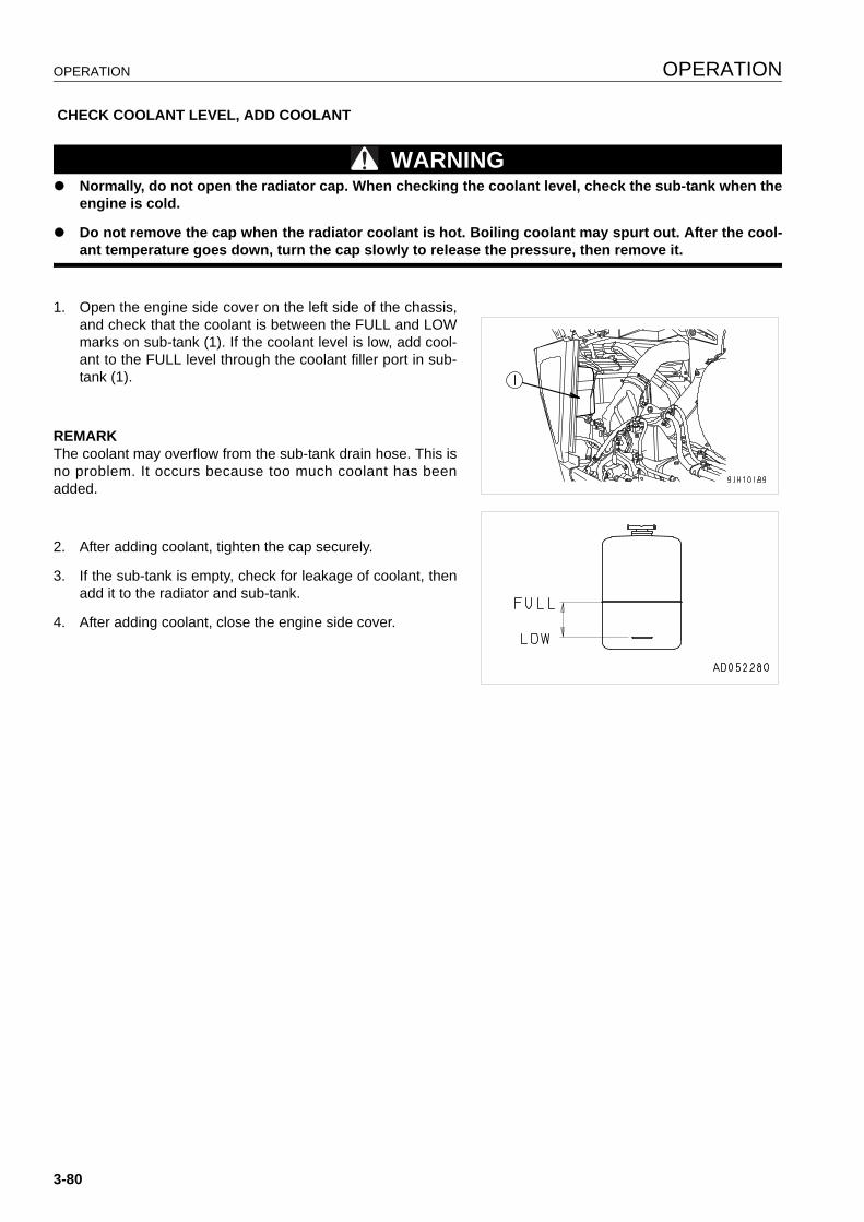
OPERATION OPERATION
CHECK COOLANT LEVEL, ADD COOLANT
WARNINGq Normally, do not open the radiator cap. When checking the coolant level, check the sub-tank when the
engine is cold.
q Do not remove the cap when the radiator coolant is hot. Boiling coolant may spurt out. After the cool-ant temperature goes down, turn the cap slowly to release the pressure, then remove it.
1. Open the engine side cover on the left side of the chassis,and check that the coolant is between the FULL and LOWmarks on sub-tank (1). If the coolant level is low, add cool-ant to the FULL level through the coolant filler port in sub-tank (1).
REMARKThe coolant may overflow from the sub-tank drain hose. This isno problem. It occurs because too much coolant has beenadded.
2. After adding coolant, tighten the cap securely.
3. If the sub-tank is empty, check for leakage of coolant, thenadd it to the radiator and sub-tank.
4. After adding coolant, close the engine side cover.
3-80
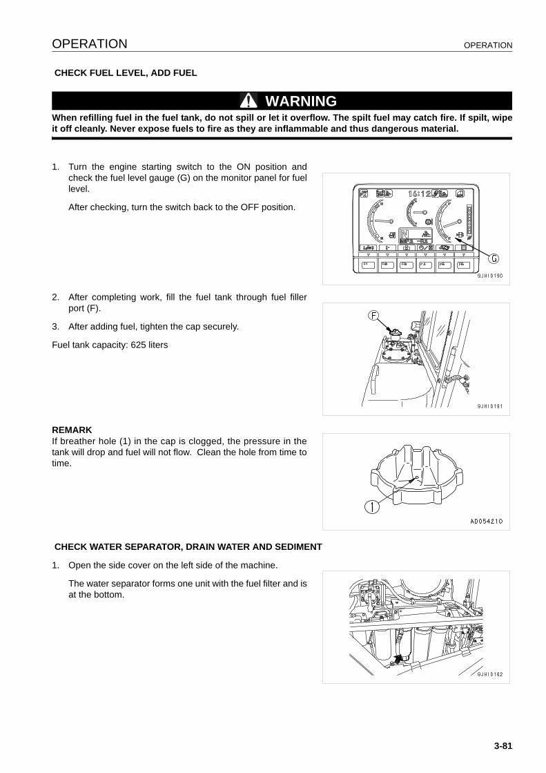
OPERATION OPERATION
CHECK FUEL LEVEL, ADD FUEL
WARNINGWhen refilling fuel in the fuel tank, do not spill or let it overflow. The spilt fuel may catch fire. If spilt, wipeit off cleanly. Never expose fuels to fire as they are inflammable and thus dangerous material.
1. Turn the engine starting switch to the ON position andcheck the fuel level gauge (G) on the monitor panel for fuellevel.
After checking, turn the switch back to the OFF position.
2. After completing work, fill the fuel tank through fuel fillerport (F).
3. After adding fuel, tighten the cap securely.
Fuel tank capacity: 625 liters
REMARKIf breather hole (1) in the cap is clogged, the pressure in thetank will drop and fuel will not flow. Clean the hole from time totime.
CHECK WATER SEPARATOR, DRAIN WATER AND SEDIMENT
1. Open the side cover on the left side of the machine.
The water separator forms one unit with the fuel filter and isat the bottom.
3-81

OPERATION OPERATION
2. It is possible to judge the water level and amount of sedi-ment by looking through transparent cap (2). If there is anywater or sediment collected at the bottom, set a containerto catch the drain water under drain hose (3).
3. Loosen plug (1) and drain the water.
4. When fuel comes out from drain hose (3), tighten plug (1)immediately.
Tightening torque: 0.2 to 0.45 N·m (0.02 to 0.046 kgf·m)
DRAIN WATER, SEDIMENT FROM FUEL TANK
Loosen drain valve (1) at the bottom of the fuel tank and drainthe sediment and water accumulated at the bottom togetherwith the fuel.
3-82
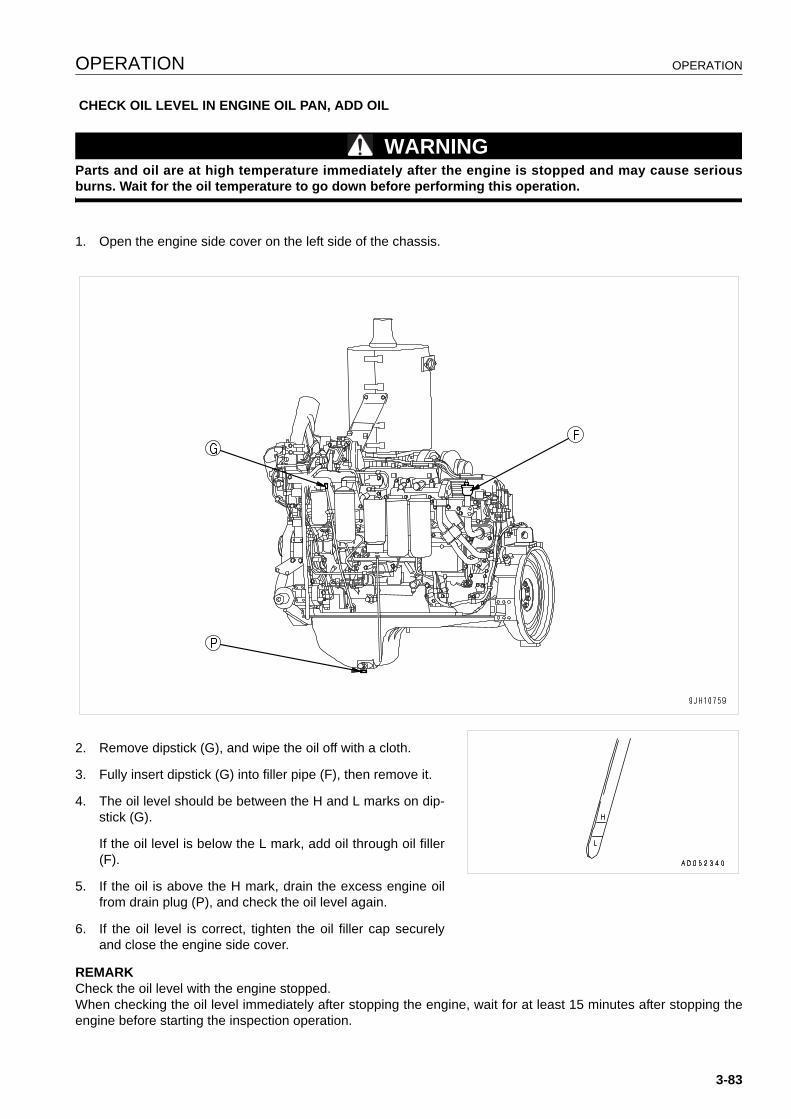
OPERATION OPERATION
CHECK OIL LEVEL IN ENGINE OIL PAN, ADD OIL
WARNINGParts and oil are at high temperature immediately after the engine is stopped and may cause seriousburns. Wait for the oil temperature to go down before performing this operation.
1. Open the engine side cover on the left side of the chassis.
2. Remove dipstick (G), and wipe the oil off with a cloth.
3. Fully insert dipstick (G) into filler pipe (F), then remove it.
4. The oil level should be between the H and L marks on dip-stick (G).
If the oil level is below the L mark, add oil through oil filler(F).
5. If the oil is above the H mark, drain the excess engine oilfrom drain plug (P), and check the oil level again.
6. If the oil level is correct, tighten the oil filler cap securelyand close the engine side cover.
REMARKCheck the oil level with the engine stopped.When checking the oil level immediately after stopping the engine, wait for at least 15 minutes after stopping theengine before starting the inspection operation.
3-83
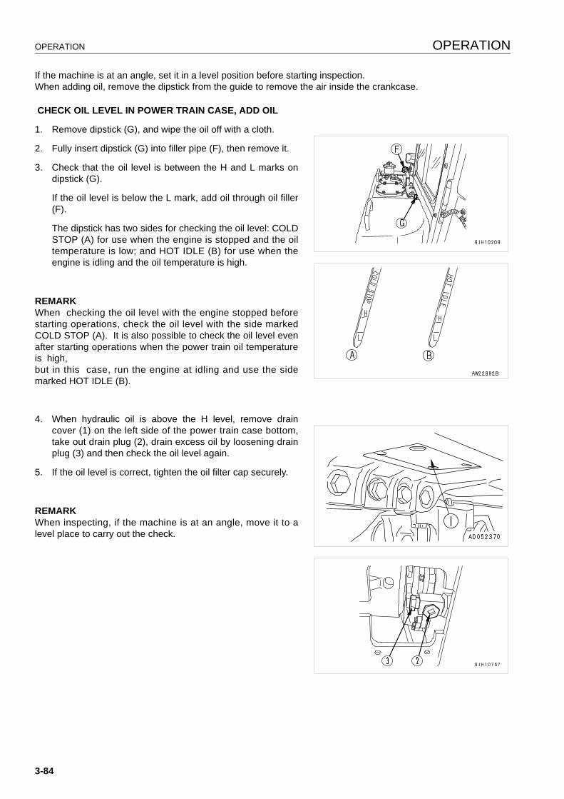
OPERATION OPERATION
If the machine is at an angle, set it in a level position before starting inspection.When adding oil, remove the dipstick from the guide to remove the air inside the crankcase.
CHECK OIL LEVEL IN POWER TRAIN CASE, ADD OIL
1. Remove dipstick (G), and wipe the oil off with a cloth.
2. Fully insert dipstick (G) into filler pipe (F), then remove it.
3. Check that the oil level is between the H and L marks ondipstick (G).
If the oil level is below the L mark, add oil through oil filler(F).
The dipstick has two sides for checking the oil level: COLDSTOP (A) for use when the engine is stopped and the oiltemperature is low; and HOT IDLE (B) for use when theengine is idling and the oil temperature is high.
REMARKWhen checking the oil level with the engine stopped beforestarting operations, check the oil level with the side markedCOLD STOP (A). It is also possible to check the oil level evenafter starting operations when the power train oil temperatureis high,but in this case, run the engine at idling and use the sidemarked HOT IDLE (B).
4. When hydraulic oil is above the H level, remove draincover (1) on the left side of the power train case bottom,take out drain plug (2), drain excess oil by loosening drainplug (3) and then check the oil level again.
5. If the oil level is correct, tighten the oil filter cap securely.
REMARKWhen inspecting, if the machine is at an angle, move it to alevel place to carry out the check.
3-84
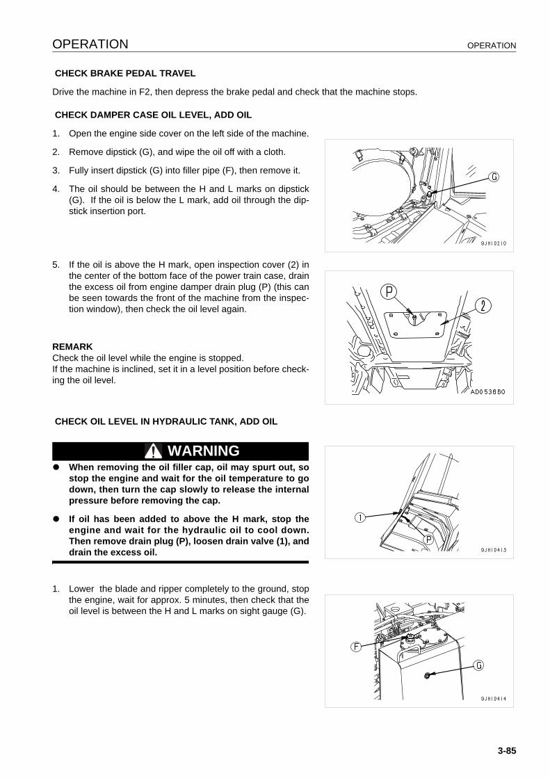
OPERATION OPERATION
CHECK BRAKE PEDAL TRAVEL
Drive the machine in F2, then depress the brake pedal and check that the machine stops.
CHECK DAMPER CASE OIL LEVEL, ADD OIL
1. Open the engine side cover on the left side of the machine.
2. Remove dipstick (G), and wipe the oil off with a cloth.
3. Fully insert dipstick (G) into filler pipe (F), then remove it.
4. The oil should be between the H and L marks on dipstick(G). If the oil is below the L mark, add oil through the dip-stick insertion port.
5. If the oil is above the H mark, open inspection cover (2) inthe center of the bottom face of the power train case, drainthe excess oil from engine damper drain plug (P) (this canbe seen towards the front of the machine from the inspec-tion window), then check the oil level again.
REMARKCheck the oil level while the engine is stopped.If the machine is inclined, set it in a level position before check-ing the oil level.
CHECK OIL LEVEL IN HYDRAULIC TANK, ADD OIL
WARNINGq When removing the oil filler cap, oil may spurt out, so
stop the engine and wait for the oil temperature to godown, then turn the cap slowly to release the internalpressure before removing the cap.
q If oil has been added to above the H mark, stop theengine and wait for the hydraulic oil to cool down.Then remove drain plug (P), loosen drain valve (1), anddrain the excess oil.
1. Lower the blade and ripper completely to the ground, stopthe engine, wait for approx. 5 minutes, then check that theoil level is between the H and L marks on sight gauge (G).
3-85
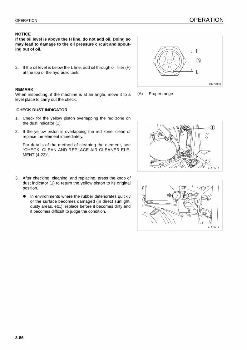
OPERATION OPERATION
NOTICEIf the oil level is above the H line, do not add oil. Doing somay lead to damage to the oil pressure circuit and spout-ing out of oil.
2. If the oil level is below the L line, add oil through oil filler (F)at the top of the hydraulic tank.
REMARKWhen inspecting, if the machine is at an angle, move it to alevel place to carry out the check.
CHECK DUST INDICATOR
1. Check for the yellow piston overlapping the red zone onthe dust indicator (1).
2. If the yellow piston is overlapping the red zone, clean orreplace the element immediately.
For details of the method of cleaning the element, see“CHECK, CLEAN AND REPLACE AIR CLEANER ELE-MENT (4-22)“.
3. After checking, cleaning, and replacing, press the knob ofdust indicator (1) to return the yellow piston to its originalposition.
q In environments where the rubber deteriorates quicklyor the surface becomes damaged (in direct sunlight,dusty areas, etc.), replace before it becomes dirty andit becomes difficult to judge the condition.
(A) Proper range
3-86
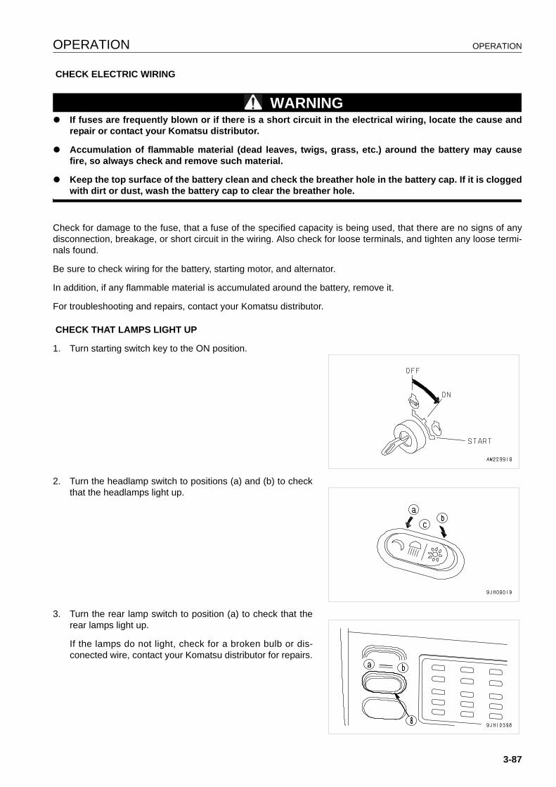
OPERATION OPERATION
CHECK ELECTRIC WIRING
WARNINGq If fuses are frequently blown or if there is a short circuit in the electrical wiring, locate the cause and
repair or contact your Komatsu distributor.
q Accumulation of flammable material (dead leaves, twigs, grass, etc.) around the battery may causefire, so always check and remove such material.
q Keep the top surface of the battery clean and check the breather hole in the battery cap. If it is cloggedwith dirt or dust, wash the battery cap to clear the breather hole.
Check for damage to the fuse, that a fuse of the specified capacity is being used, that there are no signs of anydisconnection, breakage, or short circuit in the wiring. Also check for loose terminals, and tighten any loose termi-nals found.
Be sure to check wiring for the battery, starting motor, and alternator.
In addition, if any flammable material is accumulated around the battery, remove it.
For troubleshooting and repairs, contact your Komatsu distributor.
CHECK THAT LAMPS LIGHT UP
1. Turn starting switch key to the ON position.
2. Turn the headlamp switch to positions (a) and (b) to checkthat the headlamps light up.
3. Turn the rear lamp switch to position (a) to check that therear lamps light up.
If the lamps do not light, check for a broken bulb or dis-conected wire, contact your Komatsu distributor for repairs.
3-87
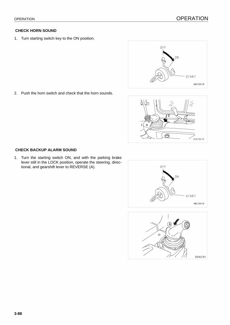
OPERATION OPERATION
CHECK HORN SOUND
1. Turn starting switch key to the ON position.
2. Push the horn switch and check that the horn sounds.
CHECK BACKUP ALARM SOUND
1. Turn the starting switch ON, and with the parking brakelever still in the LOCK position, operate the steering, direc-tional, and gearshift lever to REVERSE (A).
3-88
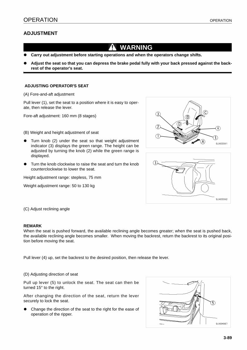
OPERATION OPERATION
ADJUSTMENT 3
WARNINGq Carry out adjustment before starting operations and when the operators change shifts.
q Adjust the seat so that you can depress the brake pedal fully with your back pressed against the back-rest of the operator's seat.
ADJUSTING OPERATOR'S SEAT
(A) Fore-and-aft adjustment
Pull lever (1), set the seat to a position where it is easy to oper-ate, then release the lever.
Fore-aft adjustment: 160 mm (8 stages)
(B) Weight and height adjustment of seat
q Turn knob (2) under the seat so that weight adjustmentindicator (3) displays the green range. The height can beadjusted by turning the knob (2) while the green range isdisplayed.
q Turn the knob clockwise to raise the seat and turn the knobcounterclockwise to lower the seat.
Height adjustment range: stepless, 75 mm
Weight adjustment range: 50 to 130 kg
(C) Adjust reclining angle
REMARKWhen the seat is pushed forward, the available reclining angle becomes greater; when the seat is pushed back,the available reclining angle becomes smaller. When moving the backrest, return the backrest to its original posi-tion before moving the seat.
Pull lever (4) up, set the backrest to the desired position, then release the lever.
(D) Adjusting direction of seat
Pull up lever (5) to unlock the seat. The seat can then beturned 15° to the right.
After changing the direction of the seat, return the leversecurely to lock the seat.
q Change the direction of the seat to the right for the ease ofoperation of the ripper.
3-89
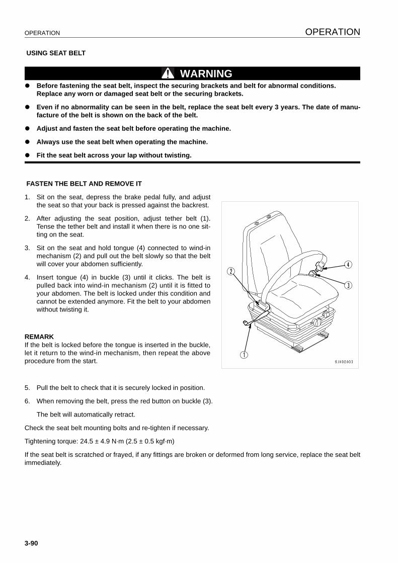
OPERATION OPERATION
USING SEAT BELT
WARNINGq Before fastening the seat belt, inspect the securing brackets and belt for abnormal conditions.
Replace any worn or damaged seat belt or the securing brackets.
q Even if no abnormality can be seen in the belt, replace the seat belt every 3 years. The date of manu-facture of the belt is shown on the back of the belt.
q Adjust and fasten the seat belt before operating the machine.
q Always use the seat belt when operating the machine.
q Fit the seat belt across your lap without twisting.
FASTEN THE BELT AND REMOVE IT
1. Sit on the seat, depress the brake pedal fully, and adjustthe seat so that your back is pressed against the backrest.
2. After adjusting the seat position, adjust tether belt (1).Tense the tether belt and install it when there is no one sit-ting on the seat.
3. Sit on the seat and hold tongue (4) connected to wind-inmechanism (2) and pull out the belt slowly so that the beltwill cover your abdomen sufficiently.
4. Insert tongue (4) in buckle (3) until it clicks. The belt ispulled back into wind-in mechanism (2) until it is fitted toyour abdomen. The belt is locked under this condition andcannot be extended anymore. Fit the belt to your abdomenwithout twisting it.
REMARKIf the belt is locked before the tongue is inserted in the buckle,let it return to the wind-in mechanism, then repeat the aboveprocedure from the start.
5. Pull the belt to check that it is securely locked in position.
6. When removing the belt, press the red button on buckle (3).
The belt will automatically retract.
Check the seat belt mounting bolts and re-tighten if necessary.
Tightening torque: 24.5 ± 4.9 N·m (2.5 ± 0.5 kgf·m)
If the seat belt is scratched or frayed, if any fittings are broken or deformed from long service, replace the seat beltimmediately.
3-90
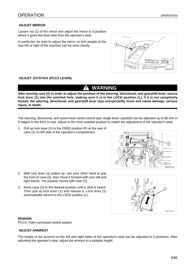
OPERATION OPERATION
ADJUST MIRROR
Loosen nut (1) of the mirror and adjust the mirror to a positionwhere it gives the best view from the operator's seat.
In particular, be sure to adjust the mirror so that people at therear left or right of the machine can be seen clearly.
ADJUST JOYSTICK (PCCS LEVER)
WARNINGAfter moving case (2) in order to adjust the position of the steering, directional, and gearshift lever, securelock lever (1) into the notched hole, making sure it is in the LOCK position (L). If it is not completelylocked, the steering, directional, and gearshift lever may unexpectedly move and cause damage, seriousinjury, or death.
The steering, directional, and speed lever (wrist control type single lever: joystick) can be adjusted up to 90 mm in9 stages to the front or rear. Adjust to the most suitable position to match the adjustment of the operator's seat.
1. Pull up lock lever (1) to the FREE position (F) at the rear ofcase (2) on left side of the operator's compartment.
2. With lock lever (1) pulled up, use your other hand to gripthe front of case (2), then move it forward with your left andright hands. The joystick moves with case (2).
3. Move case (2) to the desired position until a click is heard.Then pull up lock lever (1) and release it. Lock lever (1)automatically returns to the LOCK position (L).
REMARKPCCS: Palm command control system
ADJUST ARMREST
The height of the armrest on the left and right sides of the operator's seat can be adjusted to 3 positions. Afteradjusting the operator's seat, adjust the armrest to a suitable height.
3-91
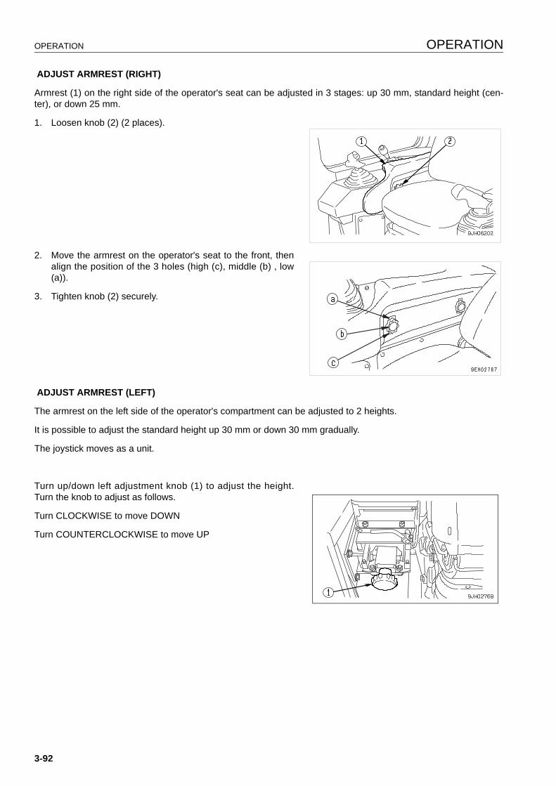
OPERATION OPERATION
ADJUST ARMREST (RIGHT)
Armrest (1) on the right side of the operator's seat can be adjusted in 3 stages: up 30 mm, standard height (cen-ter), or down 25 mm.
1. Loosen knob (2) (2 places).
2. Move the armrest on the operator's seat to the front, thenalign the position of the 3 holes (high (c), middle (b) , low(a)).
3. Tighten knob (2) securely.
ADJUST ARMREST (LEFT)
The armrest on the left side of the operator's compartment can be adjusted to 2 heights.
It is possible to adjust the standard height up 30 mm or down 30 mm gradually.
The joystick moves as a unit.
Turn up/down left adjustment knob (1) to adjust the height.Turn the knob to adjust as follows.
Turn CLOCKWISE to move DOWN
Turn COUNTERCLOCKWISE to move UP
3-92
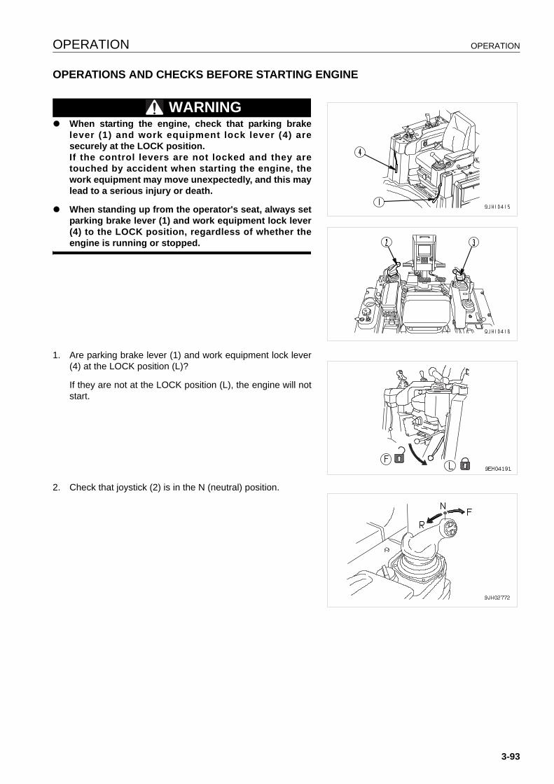
OPERATION OPERATION
OPERATIONS AND CHECKS BEFORE STARTING ENGINE 3
WARNINGq When starting the engine, check that parking brake
lever (1) and work equipment lock lever (4) aresecurely at the LOCK position.If the control levers are not locked and they aretouched by accident when starting the engine, thework equipment may move unexpectedly, and this maylead to a serious injury or death.
q When standing up from the operator's seat, always setparking brake lever (1) and work equipment lock lever(4) to the LOCK position, regardless of whether theengine is running or stopped.
1. Are parking brake lever (1) and work equipment lock lever(4) at the LOCK position (L)?
If they are not at the LOCK position (L), the engine will notstart.
2. Check that joystick (2) is in the N (neutral) position.
3-93

OPERATION OPERATION
REMARKThe engine cannot be started if joystick (steering, directional,and gearshift lever) (2) is not in the N position.If joystick (steering, directional, and gearshift lever) (2) is in For R, the letter P on display panel A will flash.
3. Lower the blade to the ground. Is blade control lever (3) atHOLD position (b)?
4. Check that the ripper is lowered to the ground.
5. Is work equipment lock lever (4) at the LOCK position?
3-94
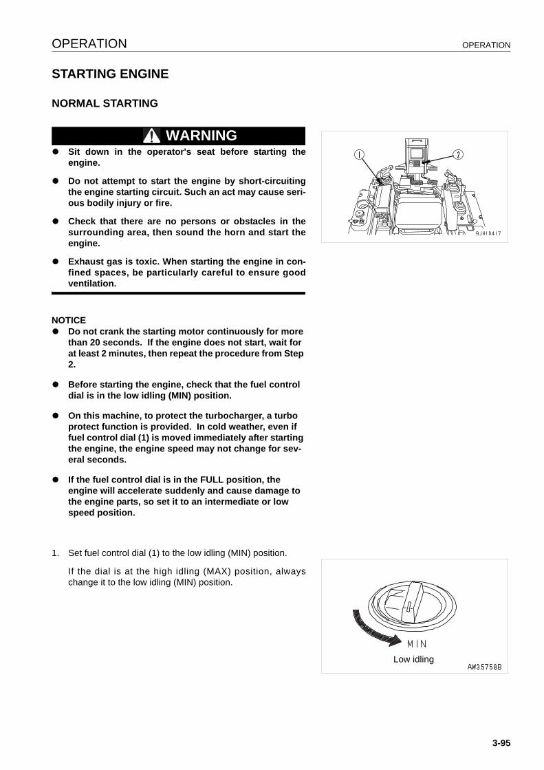
OPERATION OPERATION
STARTING ENGINE 3
NORMAL STARTING 3
WARNINGq Sit down in the operator's seat before starting the
engine.
q Do not attempt to start the engine by short-circuitingthe engine starting circuit. Such an act may cause seri-ous bodily injury or fire.
q Check that there are no persons or obstacles in thesurrounding area, then sound the horn and start theengine.
q Exhaust gas is toxic. When starting the engine in con-fined spaces, be particularly careful to ensure goodventilation.
NOTICEq Do not crank the starting motor continuously for more
than 20 seconds. If the engine does not start, wait for at least 2 minutes, then repeat the procedure from Step 2.
q Before starting the engine, check that the fuel control dial is in the low idling (MIN) position.
q On this machine, to protect the turbocharger, a turbo protect function is provided. In cold weather, even if fuel control dial (1) is moved immediately after starting the engine, the engine speed may not change for sev-eral seconds.
q If the fuel control dial is in the FULL position, the engine will accelerate suddenly and cause damage to the engine parts, so set it to an intermediate or low speed position.
1. Set fuel control dial (1) to the low idling (MIN) position.
If the dial is at the high idling (MAX) position, alwayschange it to the low idling (MIN) position.
Low idling
3-95
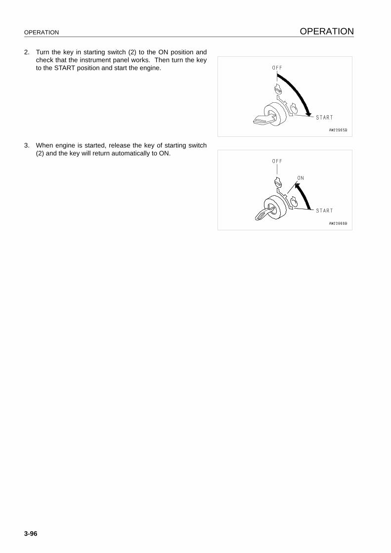
OPERATION OPERATION
2. Turn the key in starting switch (2) to the ON position andcheck that the instrument panel works. Then turn the keyto the START position and start the engine.
3. When engine is started, release the key of starting switch(2) and the key will return automatically to ON.
3-96

OPERATION OPERATION
STARTING IN COLD WEATHER 3
WARNINGq Start the engine only after sitting down in the opera-
tor's seat.
q Do not attempt to start the engine by short-circuitingthe engine starting circuit. Such an act may cause aserious bodily injury or fire.
q Check that there are no persons or obstacles in thesurrounding area, then sound the horn and start theengine.
q Never use starting aid fluids as they may cause explo-sions.
q Exhaust gas is toxic. When starting the engine in con-fined spaces, be particularly careful to ensure goodventilation.
NOTICEq Do not crank the starting motor continuously for more
than 20 seconds. If the engine does not start, wait for at least 2 minutes, then repeat the procedure from Step 2.
q Before starting the engine, check that the fuel control dial is in the low idling (MIN) position.
q On this machine, to protect the turbocharger, a turbo protect function is provided. In cold weather, even if fuel control dial (1) is moved immediately after starting the engine, the engine speed may not change for sev-eral seconds.
q If the fuel control dial is in the FULL position, the engine will accelerate suddenly and cause damage to the engine parts, so set it to an intermediate or low speed position.
1. Set fuel control dial (1) to the low idling (MIN) position.
If the dial is at the high idling (MAX) position, alwayschange it to the low idling (MIN) position.
Low idling
3-97
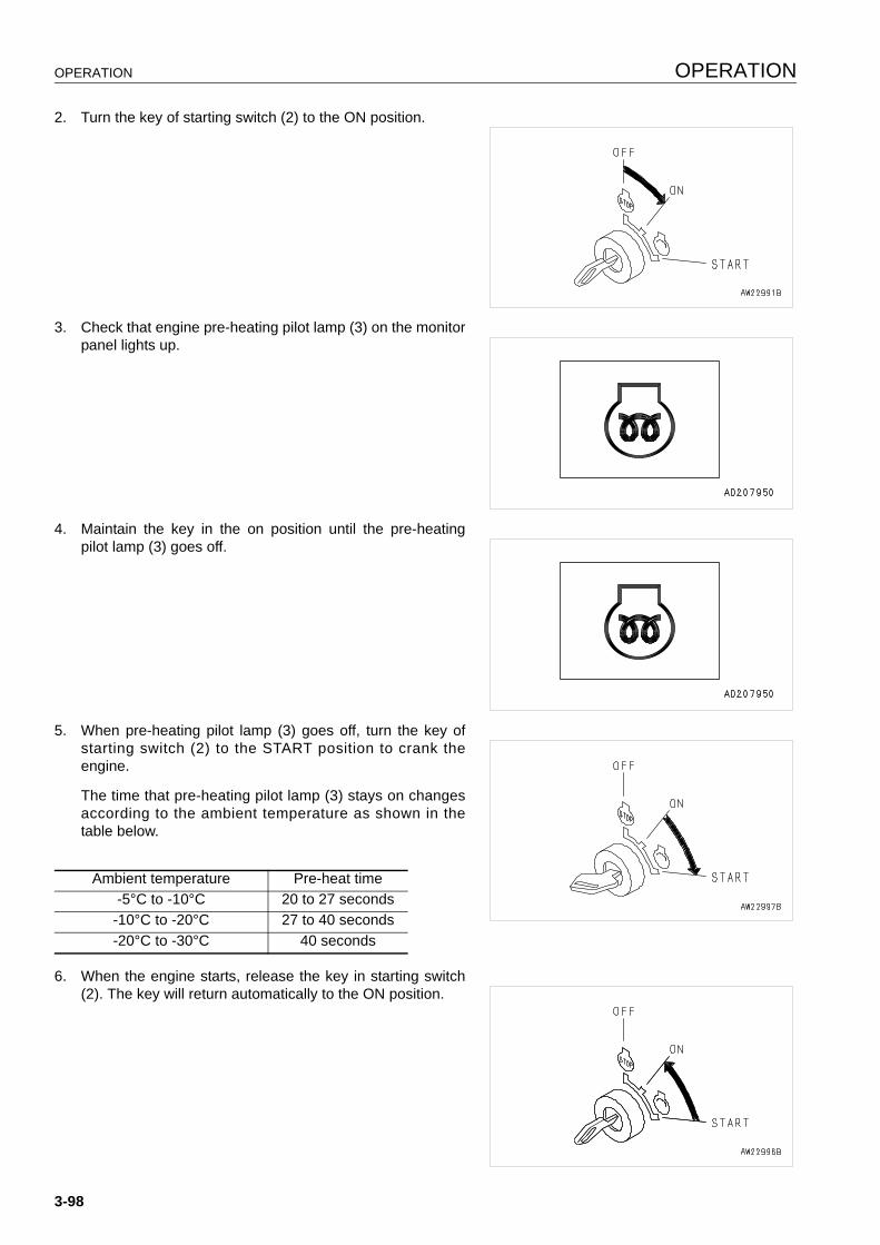
OPERATION OPERATION
2. Turn the key of starting switch (2) to the ON position.
3. Check that engine pre-heating pilot lamp (3) on the monitorpanel lights up.
4. Maintain the key in the on position until the pre-heatingpilot lamp (3) goes off.
5. When pre-heating pilot lamp (3) goes off, turn the key ofstarting switch (2) to the START position to crank theengine.
The time that pre-heating pilot lamp (3) stays on changesaccording to the ambient temperature as shown in thetable below.
6. When the engine starts, release the key in starting switch(2). The key will return automatically to the ON position.
Ambient temperature Pre-heat time-5°C to -10°C 20 to 27 seconds-10°C to -20°C 27 to 40 seconds-20°C to -30°C 40 seconds
3-98

OPERATION OPERATION
REMARKImmediately after starting the engine, run at idle. While running the engine, release the decelerator pedal and donot operate the work equipment.Guideline for idle timeCold weather: At least 15 seconds1st start after changing engine oil or engine oil filter: 20 seconds
7. When the engine rotation stabilizes, return to the low idle (MIN) position of fuel control dial (1) and then carryout the warming-up operation.
REMARKRegardless of the ambient temperature, if the key in the starting switch (2) is turned from the OFF position to theleft, pre-heating pilot lamp (3) will light up and pre-heating will start. (Pre-heating continues while the startingswitch is being held to the left.)For details of the pre-heating time, see the table in Step 5.During the pre-heating operation, pre-heating pilot lamp (3) lights up to show that pre-heating is being carried out.If the engine does not start with the above operation, wait for at least 2 minutes, and repeat the procedure in Steps3 and 4.
REMARKThe turbo protect function is a function to protect the turbocharger. It keeps the engine speed below 1000 rpm fora set time after the engine is started even if the pedal is fully depressed.The basic function acts to cancel the actuation of the turbo protect function when the engine oil pressure rises.The settings for the maximum actuation time are as shown below. When the turbo protect function is actuated, theengine speed does not change even when the fuel control dial is moved.
Coolant temperature Turbo protect time (sec.)Above 10°C 010 to -30°C Change 0 to 20below -30°C 20
3-99
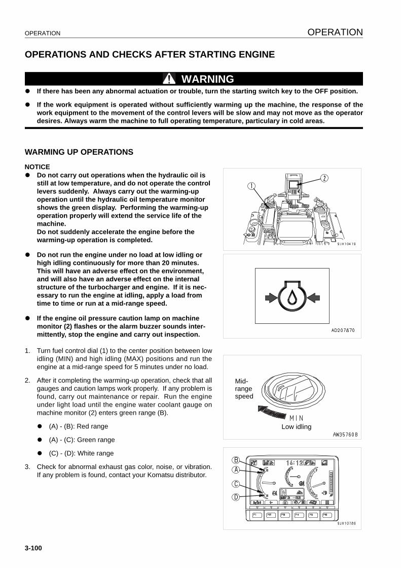
OPERATION OPERATION
OPERATIONS AND CHECKS AFTER STARTING ENGINE 3
WARNINGq If there has been any abnormal actuation or trouble, turn the starting switch key to the OFF position.
q If the work equipment is operated without sufficiently warming up the machine, the response of thework equipment to the movement of the control levers will be slow and may not move as the operatordesires. Always warm the machine to full operating temperature, particulary in cold areas.
WARMING UP OPERATIONS 3
NOTICEq Do not carry out operations when the hydraulic oil is
still at low temperature, and do not operate the control levers suddenly. Always carry out the warming-up operation until the hydraulic oil temperature monitor shows the green display. Performing the warming-up operation properly will extend the service life of the machine.Do not suddenly accelerate the engine before the warming-up operation is completed.
q Do not run the engine under no load at low idling or high idling continuously for more than 20 minutes. This will have an adverse effect on the environment, and will also have an adverse effect on the internal structure of the turbocharger and engine. If it is nec-essary to run the engine at idling, apply a load from time to time or run at a mid-range speed.
q If the engine oil pressure caution lamp on machine monitor (2) flashes or the alarm buzzer sounds inter-mittently, stop the engine and carry out inspection.
1. Turn fuel control dial (1) to the center position between lowidling (MIN) and high idling (MAX) positions and run theengine at a mid-range speed for 5 minutes under no load.
2. After it completing the warming-up operation, check that allgauges and caution lamps work properly. If any problem isfound, carry out maintenance or repair. Run the engineunder light load until the engine water coolant gauge onmachine monitor (2) enters green range (B).
q (A) - (B): Red range
q (A) - (C): Green range
q (C) - (D): White range
3. Check for abnormal exhaust gas color, noise, or vibration.If any problem is found, contact your Komatsu distributor.
Low idling
Mid-rangespeed
3-100
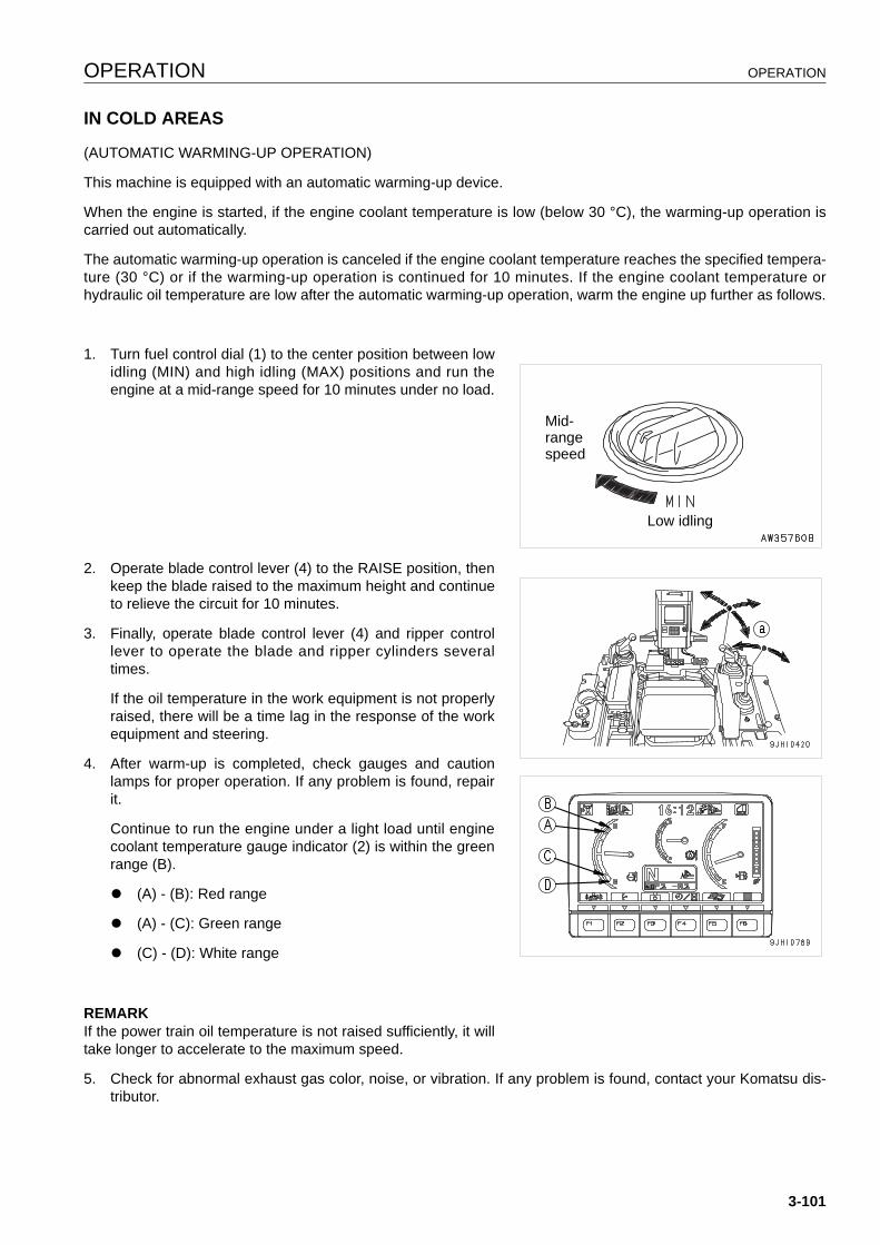
OPERATION OPERATION
IN COLD AREAS 3
(AUTOMATIC WARMING-UP OPERATION)
This machine is equipped with an automatic warming-up device.
When the engine is started, if the engine coolant temperature is low (below 30 °C), the warming-up operation iscarried out automatically.
The automatic warming-up operation is canceled if the engine coolant temperature reaches the specified tempera-ture (30 °C) or if the warming-up operation is continued for 10 minutes. If the engine coolant temperature orhydraulic oil temperature are low after the automatic warming-up operation, warm the engine up further as follows.
1. Turn fuel control dial (1) to the center position between lowidling (MIN) and high idling (MAX) positions and run theengine at a mid-range speed for 10 minutes under no load.
2. Operate blade control lever (4) to the RAISE position, thenkeep the blade raised to the maximum height and continueto relieve the circuit for 10 minutes.
3. Finally, operate blade control lever (4) and ripper controllever to operate the blade and ripper cylinders severaltimes.
If the oil temperature in the work equipment is not properlyraised, there will be a time lag in the response of the workequipment and steering.
4. After warm-up is completed, check gauges and cautionlamps for proper operation. If any problem is found, repairit.
Continue to run the engine under a light load until enginecoolant temperature gauge indicator (2) is within the greenrange (B).
q (A) - (B): Red range
q (A) - (C): Green range
q (C) - (D): White range
REMARKIf the power train oil temperature is not raised sufficiently, it willtake longer to accelerate to the maximum speed.
5. Check for abnormal exhaust gas color, noise, or vibration. If any problem is found, contact your Komatsu dis-tributor.
Low idling
Mid-rangespeed
3-101
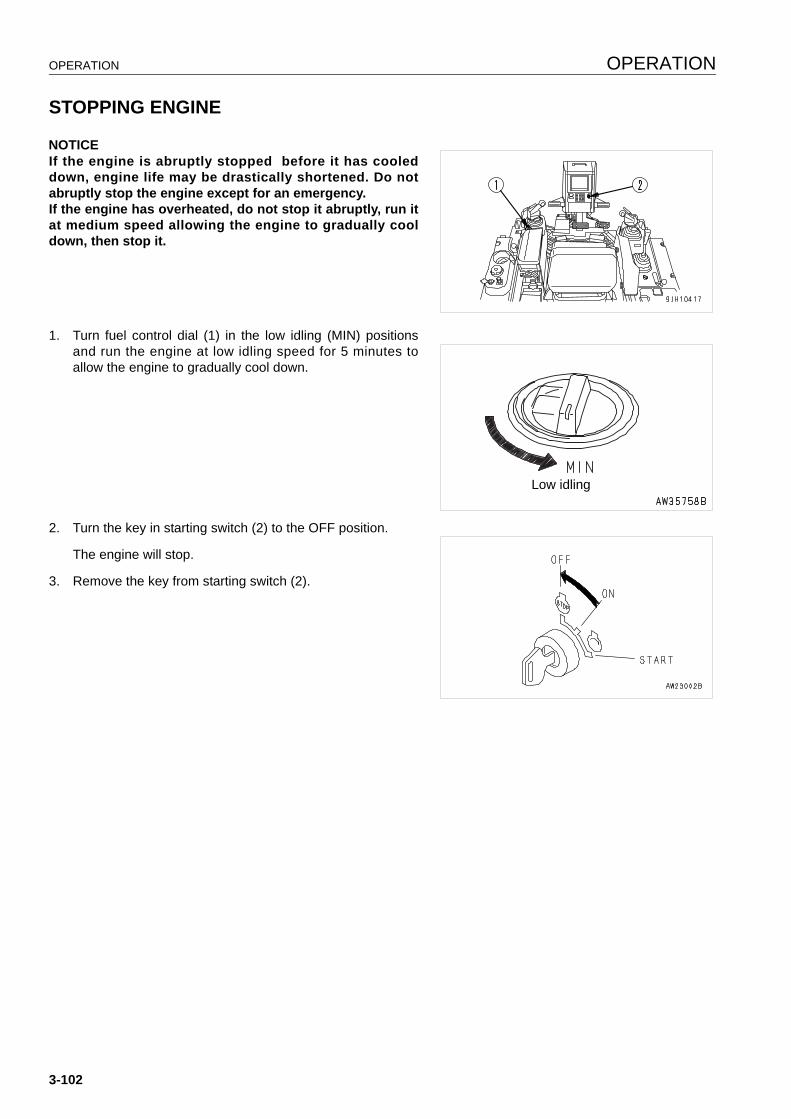
OPERATION OPERATION
STOPPING ENGINE 3
NOTICEIf the engine is abruptly stopped before it has cooleddown, engine life may be drastically shortened. Do notabruptly stop the engine except for an emergency.If the engine has overheated, do not stop it abruptly, run itat medium speed allowing the engine to gradually cooldown, then stop it.
1. Turn fuel control dial (1) in the low idling (MIN) positionsand run the engine at low idling speed for 5 minutes toallow the engine to gradually cool down.
2. Turn the key in starting switch (2) to the OFF position.
The engine will stop.
3. Remove the key from starting switch (2).
Low idling
3-102
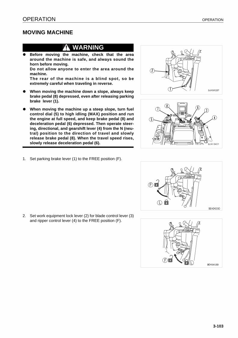
OPERATION OPERATION
MOVING MACHINE 3
WARNINGq Before moving the machine, check that the area
around the machine is safe, and always sound thehorn before moving.Do not allow anyone to enter the area around themachine.The rear of the machine is a bl ind spot, so beextremely careful when traveling in reverse.
q When moving the machine down a slope, always keepbrake pedal (8) depressed, even after releasing parkingbrake lever (1).
q When moving the machine up a steep slope, turn fuelcontrol dial (5) to high idling (MAX) position and runthe engine at full speed, and keep brake pedal (8) anddeceleration pedal (6) depressed. Then operate steer-ing, directional, and gearshift lever (4) from the N (neu-tral) position to the direction of travel and slowlyrelease brake pedal (8). When the travel speed rises,slowly release deceleration pedal (6).
1. Set parking brake lever (1) to the FREE position (F).
2. Set work equipment lock lever (2) for blade control lever (3)and ripper control lever (4) to the FREE position (F).
3-103
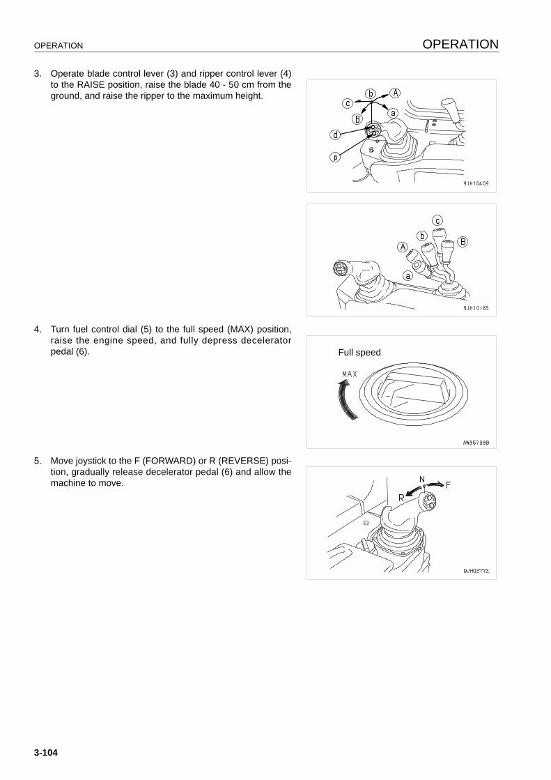
OPERATION OPERATION
3. Operate blade control lever (3) and ripper control lever (4)to the RAISE position, raise the blade 40 - 50 cm from theground, and raise the ripper to the maximum height.
4. Turn fuel control dial (5) to the full speed (MAX) position,raise the engine speed, and fully depress deceleratorpedal (6).
5. Move joystick to the F (FORWARD) or R (REVERSE) posi-tion, gradually release decelerator pedal (6) and allow themachine to move.
Full speed
3-104
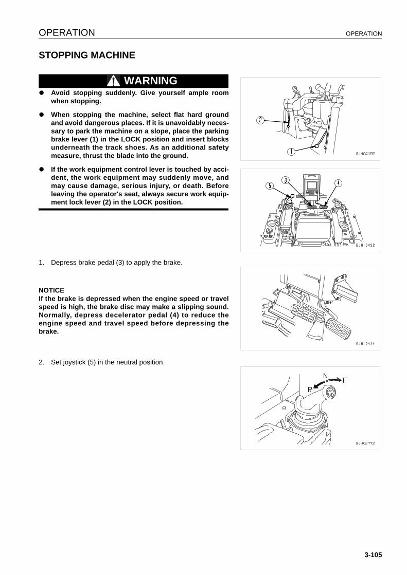
OPERATION OPERATION
STOPPING MACHINE 3
WARNINGq Avoid stopping suddenly. Give yourself ample room
when stopping.
q When stopping the machine, select flat hard groundand avoid dangerous places. If it is unavoidably neces-sary to park the machine on a slope, place the parkingbrake lever (1) in the LOCK position and insert blocksunderneath the track shoes. As an additional safetymeasure, thrust the blade into the ground.
q If the work equipment control lever is touched by acci-dent, the work equipment may suddenly move, andmay cause damage, serious injury, or death. Beforeleaving the operator's seat, always secure work equip-ment lock lever (2) in the LOCK position.
1. Depress brake pedal (3) to apply the brake.
NOTICEIf the brake is depressed when the engine speed or travelspeed is high, the brake disc may make a slipping sound.Normally, depress decelerator pedal (4) to reduce theengine speed and travel speed before depressing thebrake.
2. Set joystick (5) in the neutral position.
3-105
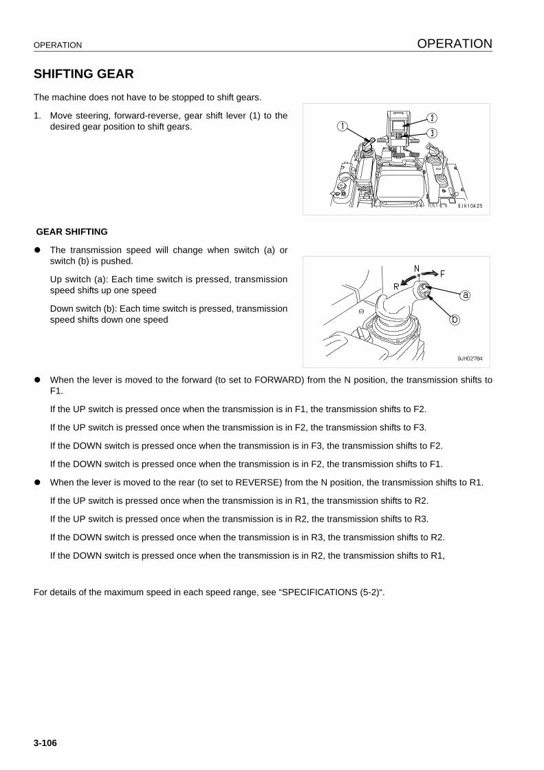
OPERATION OPERATION
SHIFTING GEAR 3
The machine does not have to be stopped to shift gears.
1. Move steering, forward-reverse, gear shift lever (1) to thedesired gear position to shift gears.
GEAR SHIFTING
q The transmission speed will change when switch (a) orswitch (b) is pushed.
Up switch (a): Each time switch is pressed, transmissionspeed shifts up one speed
Down switch (b): Each time switch is pressed, transmissionspeed shifts down one speed
q When the lever is moved to the forward (to set to FORWARD) from the N position, the transmission shifts toF1.
If the UP switch is pressed once when the transmission is in F1, the transmission shifts to F2.
If the UP switch is pressed once when the transmission is in F2, the transmission shifts to F3.
If the DOWN switch is pressed once when the transmission is in F3, the transmission shifts to F2.
If the DOWN switch is pressed once when the transmission is in F2, the transmission shifts to F1.
q When the lever is moved to the rear (to set to REVERSE) from the N position, the transmission shifts to R1.
If the UP switch is pressed once when the transmission is in R1, the transmission shifts to R2.
If the UP switch is pressed once when the transmission is in R2, the transmission shifts to R3.
If the DOWN switch is pressed once when the transmission is in R3, the transmission shifts to R2.
If the DOWN switch is pressed once when the transmission is in R2, the transmission shifts to R1,
For details of the maximum speed in each speed range, see “SPECIFICATIONS (5-2)“.
3-106
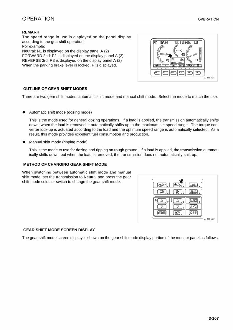
OPERATION OPERATION
REMARKThe speed range in use is displayed on the panel displayaccording to the gearshift operation.For example:Neutral: N1 is displayed on the display panel A (2)FORWARD 2nd: F2 is displayed on the display panel A (2)REVERSE 3rd: R3 is displayed on the display panel A (2)When the parking brake lever is locked, P is displayed.
OUTLINE OF GEAR SHIFT MODES
There are two gear shift modes: automatic shift mode and manual shift mode. Select the mode to match the use.
q Automatic shift mode (dozing mode)
This is the mode used for general dozing operations. If a load is applied, the transmission automatically shiftsdown; when the load is removed, it automatically shifts up to the maximum set speed range. The torque con-verter lock-up is actuated according to the load and the optimum speed range is automatically selected. As aresult, this mode provides excellent fuel consumption and production.
q Manual shift mode (ripping mode)
This is the mode to use for dozing and ripping on rough ground. If a load is applied, the transmission automat-ically shifts down, but when the load is removed, the transmission does not automatically shift up.
METHOD OF CHANGING GEAR SHIFT MODE
When switching between automatic shift mode and manualshift mode, set the transmission to Neutral and press the gearshift mode selector switch to change the gear shift mode.
GEAR SHIFT MODE SCREEN DISPLAY
The gear shift mode screen display is shown on the gear shift mode display portion of the monitor panel as follows.
3-107
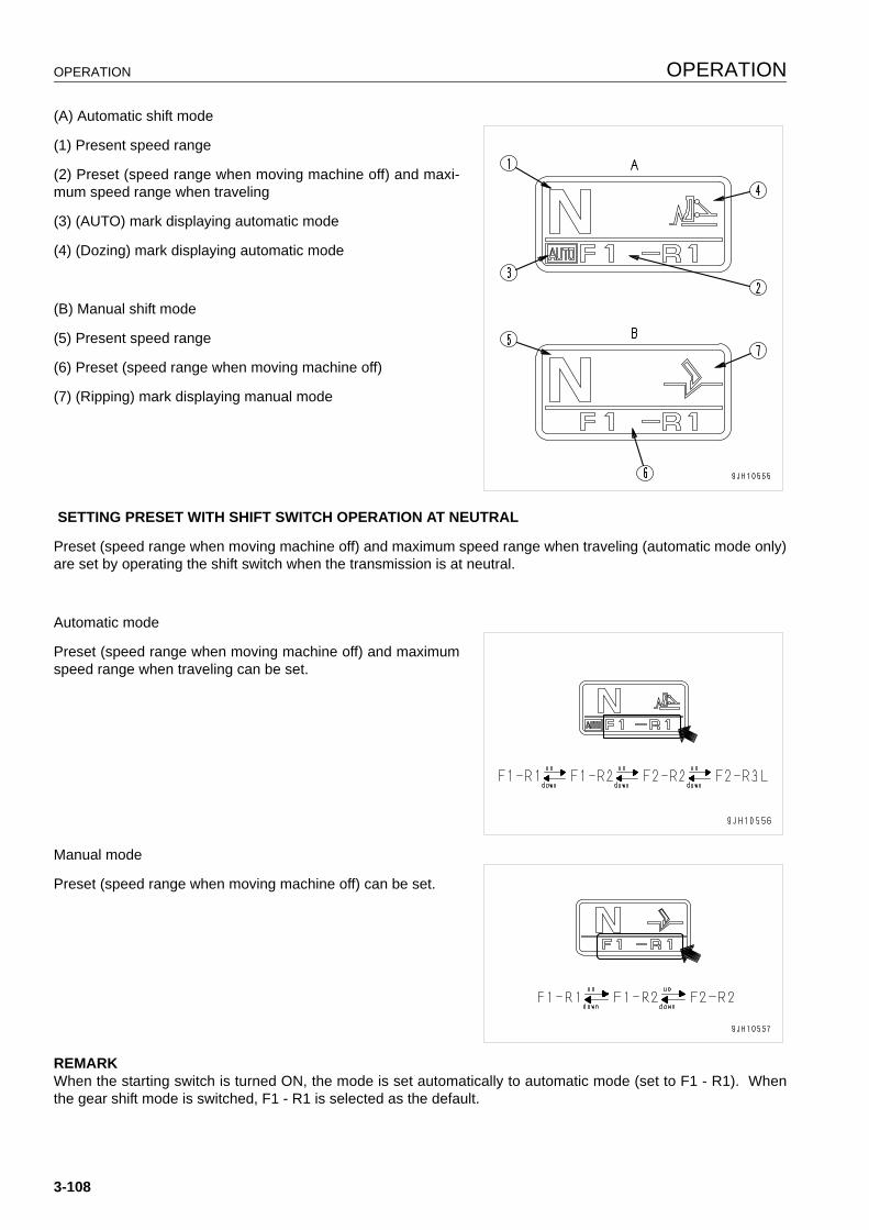
OPERATION OPERATION
(A) Automatic shift mode
(1) Present speed range
(2) Preset (speed range when moving machine off) and maxi-mum speed range when traveling
(3) (AUTO) mark displaying automatic mode
(4) (Dozing) mark displaying automatic mode
(B) Manual shift mode
(5) Present speed range
(6) Preset (speed range when moving machine off)
(7) (Ripping) mark displaying manual mode
SETTING PRESET WITH SHIFT SWITCH OPERATION AT NEUTRAL
Preset (speed range when moving machine off) and maximum speed range when traveling (automatic mode only)are set by operating the shift switch when the transmission is at neutral.
Automatic mode
Preset (speed range when moving machine off) and maximumspeed range when traveling can be set.
Manual mode
Preset (speed range when moving machine off) can be set.
REMARKWhen the starting switch is turned ON, the mode is set automatically to automatic mode (set to F1 - R1). Whenthe gear shift mode is switched, F1 - R1 is selected as the default.
3-108

OPERATION OPERATION
GEARSHIFTING OPERATION USING PRESET MODE FUNCTION
q Shift mode selection means that the selected speed range is displayed in the N position before starting.
q When the joystick is in the N position, if UP switch (a) orDOWN switch (b) is pressed, the shift mode selection canbe carried out.
q F1-R1 mode
q F1-R2 mode
q F2-R2 mode
q The selected shift mode is displayed on the speed rangedisplay on the machine monitor.
q Shift operation when F1-R1 mode is set
After this mode is set, when the joystick (steering, direc-tional, and gearshift lever) is operated to the front (FOR-WARD operation), the speed range shifts to F1. When thelever is moved to the rear (REVERSE operation), thespeed range shifts to R1.
q Shift operation when [F1-R2] mode is set
When the steering, directional, and speed lever is in the N position, if the up switch is pressed once, the modeis set to [F1-R2] mode. After that, if the steering, directional, and speed lever is operated forward (forwardtravel operation), the transmission is shifted to F1. If it is moved back (reverse travel operation), the transmis-sion is shifted to R2.
q Shift operation when [F2-R2] mode is set
When the steering, directional, and speed lever is in the N position, if the up switch is pressed twice, the modeis set to [F2-R2] mode. After that, if the steering, directional, and speed lever is operated forward (forwardtravel operation), the transmission is shifted to F2. If it is moved back (reverse travel operation), the transmis-sion is shifted to R2.
SHIFTING SPEED RANGE BY OPERATING SWIFT SWITCH WHEN TRAVELING
It is possible to operate the shift switch when traveling to change the maximum set speed range when traveling(automatic shift mode) or speed range used when traveling (manual shift mode).
3-109
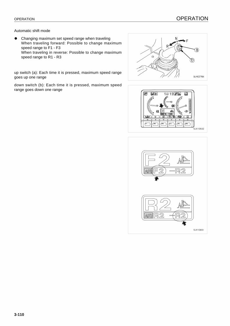
OPERATION OPERATION
Automatic shift mode
q Changing maximum set speed range when travelingWhen traveling forward: Possible to change maximumspeed range to F1 - F3When traveling in reverse: Possible to change maximumspeed range to R1 - R3
up switch (a): Each time it is pressed, maximum speed rangegoes up one range
down switch (b): Each time it is pressed, maximum speedrange goes down one range
3-110
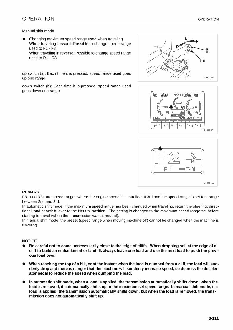
OPERATION OPERATION
Manual shift mode
q Changing maximum speed range used when travelingWhen traveling forward: Possible to change speed rangeused to F1 - F3When traveling in reverse: Possible to change speed rangeused to R1 - R3
up switch (a): Each time it is pressed, speed range used goesup one range
down switch (b): Each time it is pressed, speed range usedgoes down one range
REMARKF3L and R3L are speed ranges where the engine speed is controlled at 3rd and the speed range is set to a rangebetween 2nd and 3rd.In automatic shift mode, if the maximum speed range has been changed when traveling, return the steering, direc-tional, and gearshift lever to the Neutral position. The setting is changed to the maximum speed range set beforestarting to travel (when the transmission was at neutral).In manual shift mode, the preset (speed range when moving machine off) cannot be changed when the machine istraveling.
NOTICEq Be careful not to come unnecessarily close to the edge of cliffs. When dropping soil at the edge of a
cliff to build an embankment or landfill, always leave one load and use the next load to push the previ-ous load over.
q When reaching the top of a hill, or at the instant when the load is dumped from a cliff, the load will sud-denly drop and there is danger that the machine will suddenly increase speed, so depress the deceler-ator pedal to reduce the speed when dumping the load.
q In automatic shift mode, when a load is applied, the transmission automatically shifts down; when the load is removed, it automatically shifts up to the maximum set speed range. In manual shift mode, if a load is applied, the transmission automatically shifts down, but when the load is removed, the trans-mission does not automatically shift up.
3-111
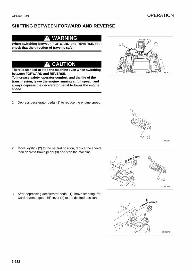
OPERATION OPERATION
SHIFTING BETWEEN FORWARD AND REVERSE 3
WARNINGWhen switching between FORWARD and REVERSE, firstcheck that the direction of travel is safe.
CAUTIONThere is no need to stop the machine even when switching between FORWARD and REVERSE.To increase safety, operator comfort, and the life of the transmission, leave the engine running at full speed, and always depress the decelerator pedal to lower the engine speed.
1. Depress decelerator pedal (1) to reduce the engine speed.
2. Move joystick (2) to the neutral position, reduce the speed,then depress brake pedal (3) and stop the machine.
3. After depressing decelerator pedal (1), move steering, for-ward-reverse, gear shift lever (2) to the desired position.
3-112
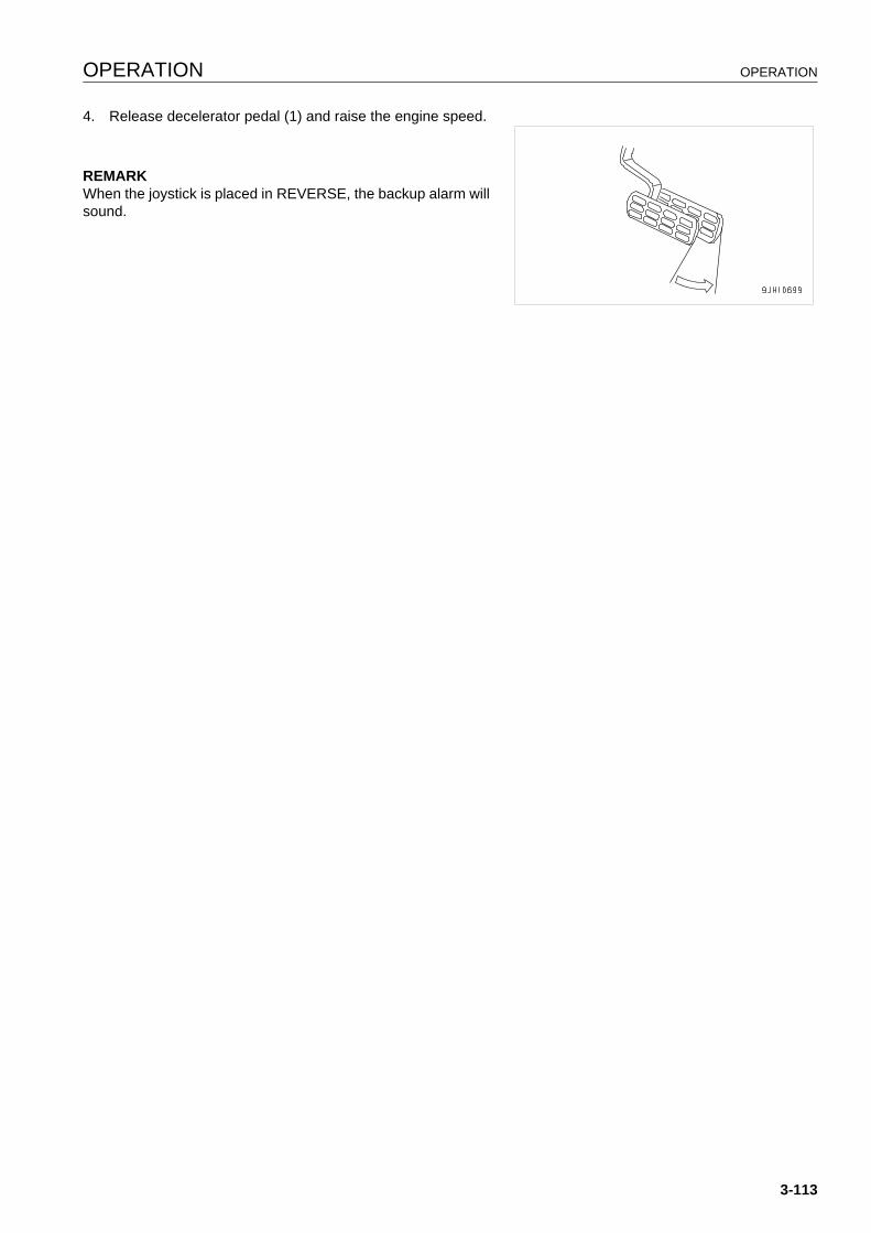
OPERATION OPERATION
4. Release decelerator pedal (1) and raise the engine speed.
REMARKWhen the joystick is placed in REVERSE, the backup alarm willsound.
3-113
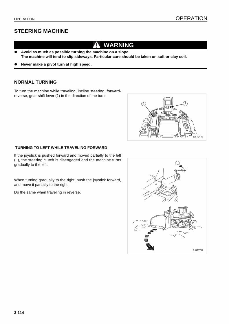
OPERATION OPERATION
STEERING MACHINE 3
WARNINGq Avoid as much as possible turning the machine on a slope.
The machine will tend to slip sideways. Particular care should be taken on soft or clay soil.
q Never make a pivot turn at high speed.
NORMAL TURNING 3
To turn the machine while traveling, incline steering, forward-reverse, gear shift lever (1) in the direction of the turn.
TURNING TO LEFT WHILE TRAVELING FORWARD
If the joystick is pushed forward and moved partially to the left(L), the steering clutch is disengaged and the machine turnsgradually to the left.
When turning gradually to the right, push the joystick forward,and move it partially to the right.
Do the same when traveling in reverse.
3-114
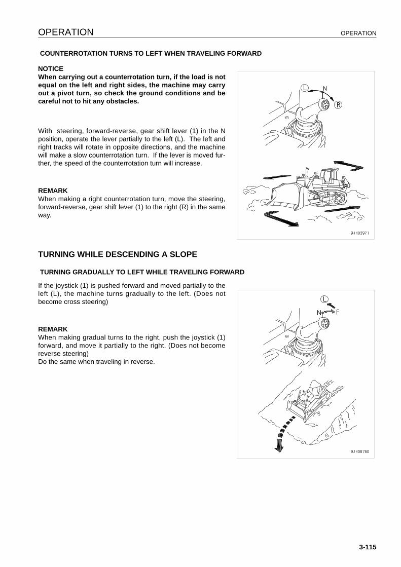
OPERATION OPERATION
COUNTERROTATION TURNS TO LEFT WHEN TRAVELING FORWARD
NOTICEWhen carrying out a counterrotation turn, if the load is notequal on the left and right sides, the machine may carryout a pivot turn, so check the ground conditions and becareful not to hit any obstacles.
With steering, forward-reverse, gear shift lever (1) in the Nposition, operate the lever partially to the left (L). The left andright tracks will rotate in opposite directions, and the machinewill make a slow counterrotation turn. If the lever is moved fur-ther, the speed of the counterrotation turn will increase.
REMARKWhen making a right counterrotation turn, move the steering,forward-reverse, gear shift lever (1) to the right (R) in the sameway.
TURNING WHILE DESCENDING A SLOPE 3
TURNING GRADUALLY TO LEFT WHILE TRAVELING FORWARD
If the joystick (1) is pushed forward and moved partially to theleft (L), the machine turns gradually to the left. (Does notbecome cross steering)
REMARKWhen making gradual turns to the right, push the joystick (1)forward, and move it partially to the right. (Does not becomereverse steering)Do the same when traveling in reverse.
3-115
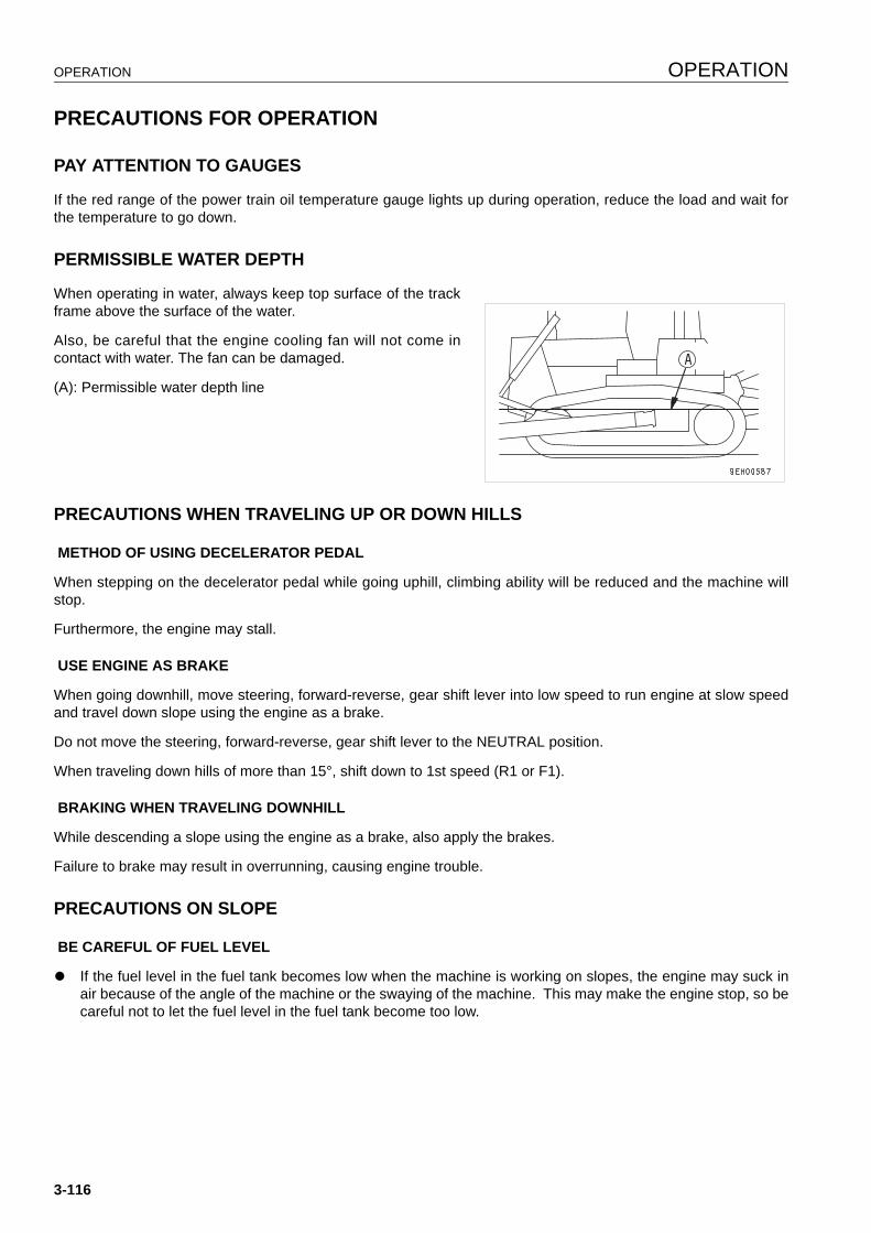
OPERATION OPERATION
PRECAUTIONS FOR OPERATION 3
PAY ATTENTION TO GAUGES 3
If the red range of the power train oil temperature gauge lights up during operation, reduce the load and wait forthe temperature to go down.
PERMISSIBLE WATER DEPTH 3
When operating in water, always keep top surface of the trackframe above the surface of the water.
Also, be careful that the engine cooling fan will not come incontact with water. The fan can be damaged.
(A): Permissible water depth line
PRECAUTIONS WHEN TRAVELING UP OR DOWN HILLS 3
METHOD OF USING DECELERATOR PEDAL
When stepping on the decelerator pedal while going uphill, climbing ability will be reduced and the machine willstop.
Furthermore, the engine may stall.
USE ENGINE AS BRAKE
When going downhill, move steering, forward-reverse, gear shift lever into low speed to run engine at slow speedand travel down slope using the engine as a brake.
Do not move the steering, forward-reverse, gear shift lever to the NEUTRAL position.
When traveling down hills of more than 15°, shift down to 1st speed (R1 or F1).
BRAKING WHEN TRAVELING DOWNHILL
While descending a slope using the engine as a brake, also apply the brakes.
Failure to brake may result in overrunning, causing engine trouble.
PRECAUTIONS ON SLOPE 3
BE CAREFUL OF FUEL LEVEL
q If the fuel level in the fuel tank becomes low when the machine is working on slopes, the engine may suck inair because of the angle of the machine or the swaying of the machine. This may make the engine stop, so becareful not to let the fuel level in the fuel tank become too low.
3-116
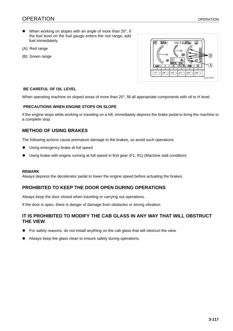
OPERATION OPERATION
q When working on slopes with an angle of more than 20°, ifthe fuel level on the fuel gauge enters the red range, addfuel immediately.
(A): Red range
(B): Green range
BE CAREFUL OF OIL LEVEL
When operating machine on sloped areas of more than 20°, fill all appropriate components with oil to H level.
PRECAUTIONS WHEN ENGINE STOPS ON SLOPE
If the engine stops while working or traveling on a hill, immediately depress the brake pedal to bring the machine toa complete stop.
METHOD OF USING BRAKES 3
The following actions cause premature damage to the brakes, so avoid such operations.
q Using emergency brake at full speed
q Using brake with engine running at full speed in first gear (F1, R1) (Machine stall condition)
REMARKAlways depress the decelerator pedal to lower the engine speed before actuating the brakes.
PROHIBITED TO KEEP THE DOOR OPEN DURING OPERATIONS 3
Always keep the door closed when traveling or carrying out operations.
If the door is open, there is danger of damage from obstacles or strong vibration.
IT IS PROHIBITED TO MODIFY THE CAB GLASS IN ANY WAY THAT WILL OBSTRUCT THE VIEW 3
q For safety reasons, do not install anything on the cab glass that will obstruct the view.
q Always keep the glass clean to ensure safety during operations.
3-117
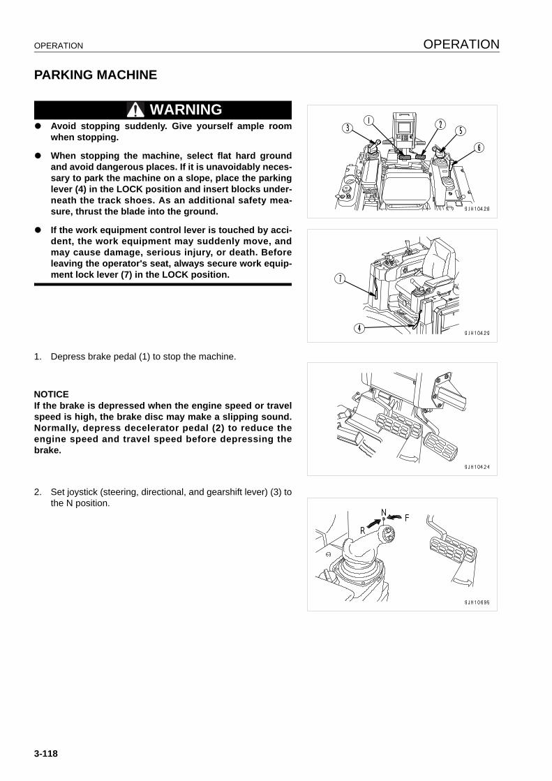
OPERATION OPERATION
PARKING MACHINE 3
WARNINGq Avoid stopping suddenly. Give yourself ample room
when stopping.
q When stopping the machine, select flat hard groundand avoid dangerous places. If it is unavoidably neces-sary to park the machine on a slope, place the parkinglever (4) in the LOCK position and insert blocks under-neath the track shoes. As an additional safety mea-sure, thrust the blade into the ground.
q If the work equipment control lever is touched by acci-dent, the work equipment may suddenly move, andmay cause damage, serious injury, or death. Beforeleaving the operator's seat, always secure work equip-ment lock lever (7) in the LOCK position.
1. Depress brake pedal (1) to stop the machine.
NOTICEIf the brake is depressed when the engine speed or travelspeed is high, the brake disc may make a slipping sound.Normally, depress decelerator pedal (2) to reduce theengine speed and travel speed before depressing thebrake.
2. Set joystick (steering, directional, and gearshift lever) (3) tothe N position.
3-118

OPERATION OPERATION
3. Operate parking lever (4) to lock (L) the brakes.
4. Operate blade control lever (5) and ripper control lever (6)to LOWER position (c) and lower the blade and ripper tothe ground.
5. Place blade control lever (5) and ripper control lever (6) atHOLD position (b).
6. Set work equipment lock lever (7) for blade control lever (5)and ripper control lever (6) to the FREE position (F).
CHECK AFTER STOPPING ENGINE 3
1. Walk around the machine and check the work equipment, machine exterior, and undercarriage, also check forany leakage of oil or coolant. If any problems are found, repair them.
2. Fill the fuel tank.
3. Check the engine compartment for paper and debris. Clean out any paper and debris to avoid a fire hazard.
4. Remove any mud affixed to the undercarriage.
3-119

OPERATION OPERATION
CHECK AFTER FINISHING WORK 3
Check the engine coolant temperature, engine oil pressure,and fuel level on the machine monitor.
LOCKING 3
To prevent vandalism, there are locks in the following places.
Places that can be locked with the starting switch key.
q Left and right engine side covers (1) (left side: 1 place; right
side: 1 place)
q Battery inspection cover (2)
q Cab door opener (3)
q Cap with lock (4) (if equipped)
q Radiator cap
q Fuel tank cap
q Hydraulic tank cap
q Hydraulic tank breather
q Power train oil filler tube cap
RIPPER OPERATION 3
EFFECTIVE METHOD OF USE 3
q The most suitable digging angle for the shank is when theshank is perpendicular to the ground surface (angle at tip:45° - 50°).
q For comparatively soft rock (seismic velocity: 1200m/s orbelow), it is also possible to carry out ripping with the shanktilted to the rear (maximum ripping angle).
3-120
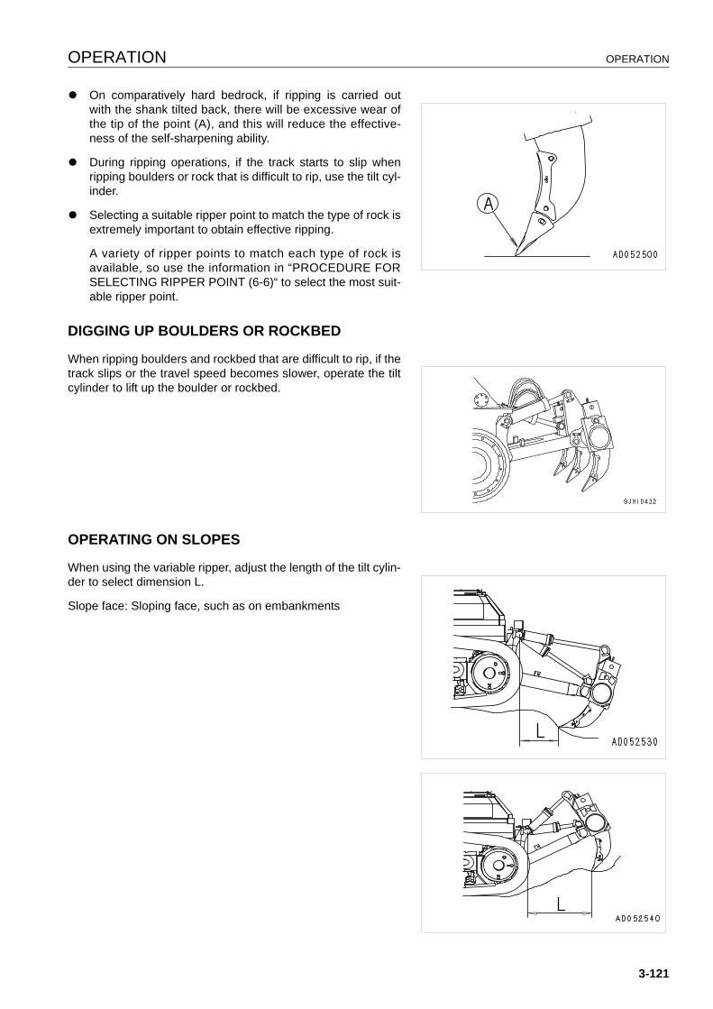
OPERATION OPERATION
q On comparatively hard bedrock, if ripping is carried outwith the shank tilted back, there will be excessive wear ofthe tip of the point (A), and this will reduce the effective-ness of the self-sharpening ability.
q During ripping operations, if the track starts to slip whenripping boulders or rock that is difficult to rip, use the tilt cyl-inder.
q Selecting a suitable ripper point to match the type of rock isextremely important to obtain effective ripping.
A variety of ripper points to match each type of rock isavailable, so use the information in “PROCEDURE FORSELECTING RIPPER POINT (6-6)“ to select the most suit-able ripper point.
DIGGING UP BOULDERS OR ROCKBED 3
When ripping boulders and rockbed that are difficult to rip, if thetrack slips or the travel speed becomes slower, operate the tiltcylinder to lift up the boulder or rockbed.
OPERATING ON SLOPES 3
When using the variable ripper, adjust the length of the tilt cylin-der to select dimension L.
Slope face: Sloping face, such as on embankments
3-121
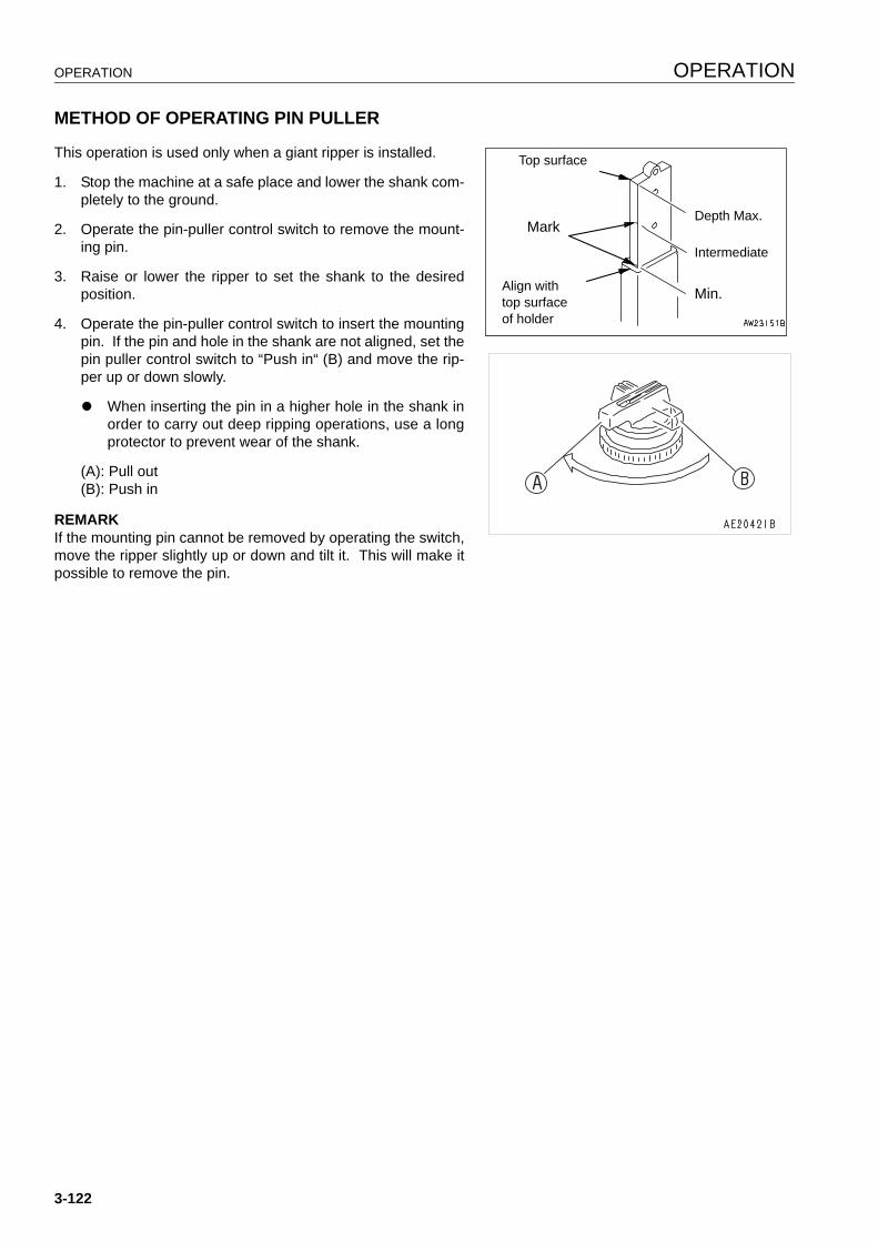
OPERATION OPERATION
METHOD OF OPERATING PIN PULLER 3
This operation is used only when a giant ripper is installed.
1. Stop the machine at a safe place and lower the shank com-pletely to the ground.
2. Operate the pin-puller control switch to remove the mount-ing pin.
3. Raise or lower the ripper to set the shank to the desiredposition.
4. Operate the pin-puller control switch to insert the mountingpin. If the pin and hole in the shank are not aligned, set thepin puller control switch to “Push in“ (B) and move the rip-per up or down slowly.
q When inserting the pin in a higher hole in the shank inorder to carry out deep ripping operations, use a longprotector to prevent wear of the shank.
(A): Pull out(B): Push in
REMARKIf the mounting pin cannot be removed by operating the switch,move the ripper slightly up or down and tilt it. This will make itpossible to remove the pin.
Top surface
Mark
Align withtop surfaceof holder
Depth Max.
Intermediate
Min.
3-122
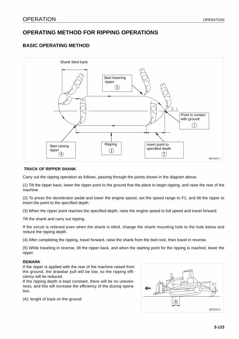
OPERATION OPERATION
OPERATING METHOD FOR RIPPING OPERATIONS 3
BASIC OPERATING METHOD 3
TRACK OF RIPPER SHANK
Carry out the ripping operation as follows, passing through the points shown in the diagram above.
(1) Tilt the ripper back, lower the ripper point to the ground that the place to begin ripping, and raise the rear of themachine.
(2) To press the decelerator pedal and lower the engine speed, set the speed range to F1, and tilt the ripper toinsert the point to the specified depth.
(3) When the ripper point reaches the specified depth, raise the engine speed to full speed and travel forward.
Tilt the shank and carry out ripping.
If the circuit is relieved even when the shank is tilted, change the shank mounting hole to the hole below andreduce the ripping depth.
(4) After completing the ripping, travel forward, raise the shank from the bed rock, then travel in reverse.
(5) While traveling in reverse, tilt the ripper back, and when the starting point for the ripping is reached, lower theripper.
REMARKIf the ripper is applied with the rear of the machine raised fromthe ground, the drawbar pull will be low, so the ripping effi-ciency will be reduced.If the ripping depth is kept constant, there will be no uneven-ness, and this will increase the efficiency of the dozing opera-tion.
(A): lenght of track on the ground
Shank tilted back
Start lowering ripper
Point in contact with ground
Insert point to specified depth
RippingStart raising ripper
3-123
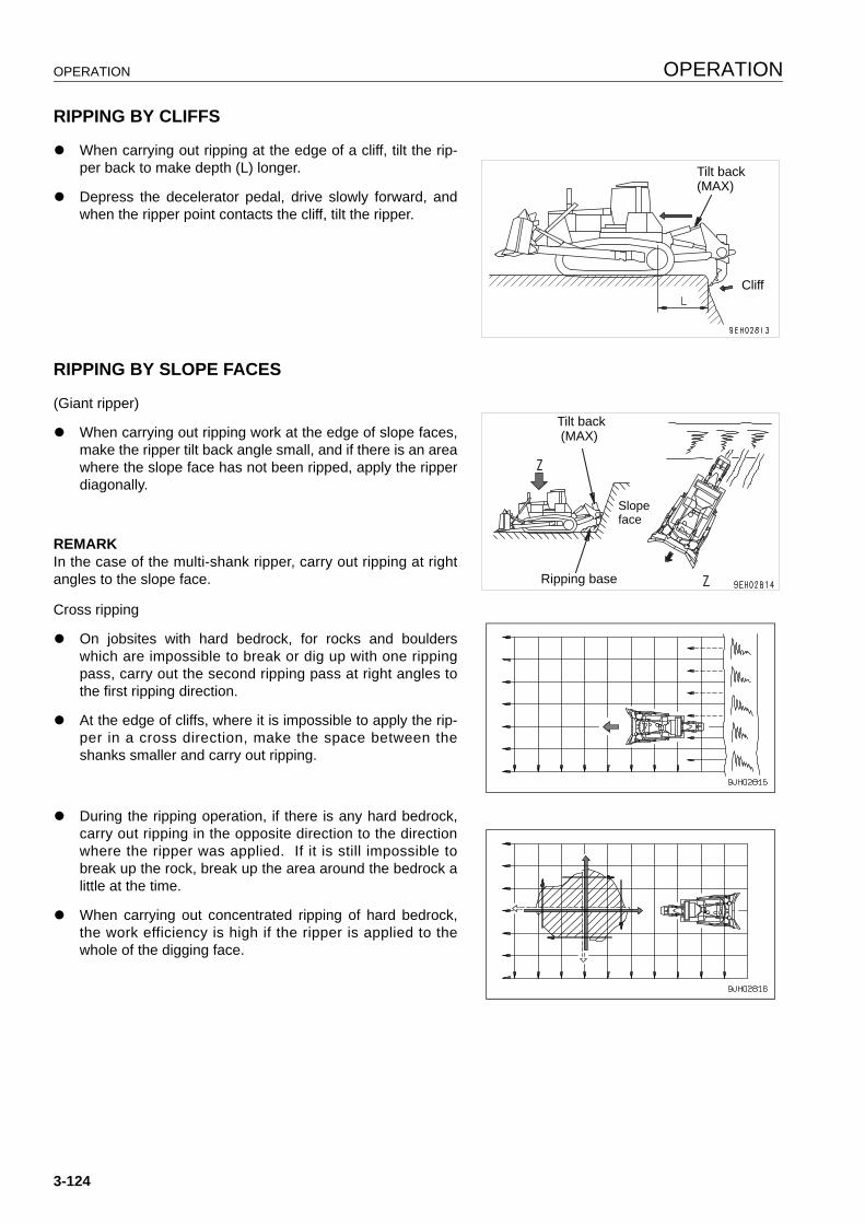
OPERATION OPERATION
RIPPING BY CLIFFS 3
q When carrying out ripping at the edge of a cliff, tilt the rip-per back to make depth (L) longer.
q Depress the decelerator pedal, drive slowly forward, andwhen the ripper point contacts the cliff, tilt the ripper.
RIPPING BY SLOPE FACES 3
(Giant ripper)
q When carrying out ripping work at the edge of slope faces,make the ripper tilt back angle small, and if there is an areawhere the slope face has not been ripped, apply the ripperdiagonally.
REMARKIn the case of the multi-shank ripper, carry out ripping at rightangles to the slope face.
Cross ripping
q On jobsites with hard bedrock, for rocks and boulderswhich are impossible to break or dig up with one rippingpass, carry out the second ripping pass at right angles tothe first ripping direction.
q At the edge of cliffs, where it is impossible to apply the rip-per in a cross direction, make the space between theshanks smaller and carry out ripping.
q During the ripping operation, if there is any hard bedrock,carry out ripping in the opposite direction to the directionwhere the ripper was applied. If it is still impossible tobreak up the rock, break up the area around the bedrock alittle at the time.
q When carrying out concentrated ripping of hard bedrock,the work efficiency is high if the ripper is applied to thewhole of the digging face.
Tilt back (MAX)
Cliff
Tilt back (MAX)
Ripping base
Slope face
3-124
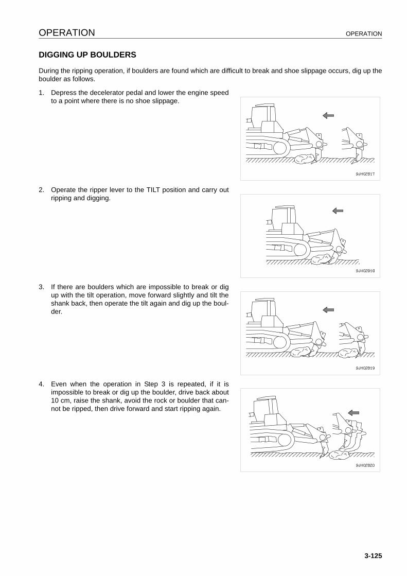
OPERATION OPERATION
DIGGING UP BOULDERS 3
During the ripping operation, if boulders are found which are difficult to break and shoe slippage occurs, dig up theboulder as follows.
1. Depress the decelerator pedal and lower the engine speedto a point where there is no shoe slippage.
2. Operate the ripper lever to the TILT position and carry outripping and digging.
3. If there are boulders which are impossible to break or digup with the tilt operation, move forward slightly and tilt theshank back, then operate the tilt again and dig up the boul-der.
4. Even when the operation in Step 3 is repeated, if it isimpossible to break or dig up the boulder, drive back about10 cm, raise the shank, avoid the rock or boulder that can-not be ripped, then drive forward and start ripping again.
3-125
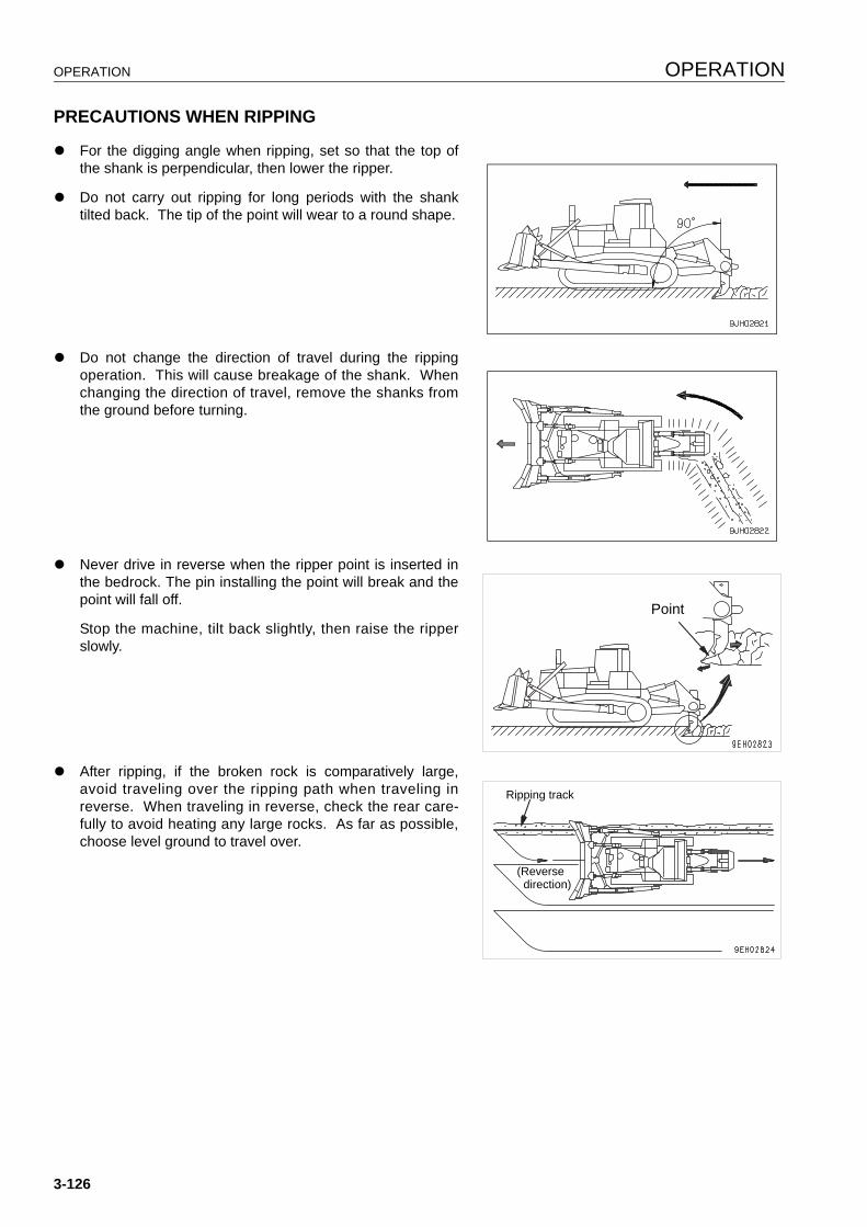
OPERATION OPERATION
PRECAUTIONS WHEN RIPPING 3
q For the digging angle when ripping, set so that the top ofthe shank is perpendicular, then lower the ripper.
q Do not carry out ripping for long periods with the shanktilted back. The tip of the point will wear to a round shape.
q Do not change the direction of travel during the rippingoperation. This will cause breakage of the shank. Whenchanging the direction of travel, remove the shanks fromthe ground before turning.
q Never drive in reverse when the ripper point is inserted inthe bedrock. The pin installing the point will break and thepoint will fall off.
Stop the machine, tilt back slightly, then raise the ripperslowly.
q After ripping, if the broken rock is comparatively large,avoid traveling over the ripping path when traveling inreverse. When traveling in reverse, check the rear care-fully to avoid heating any large rocks. As far as possible,choose level ground to travel over.
Point
Ripping track
(Reverse direction)
3-126
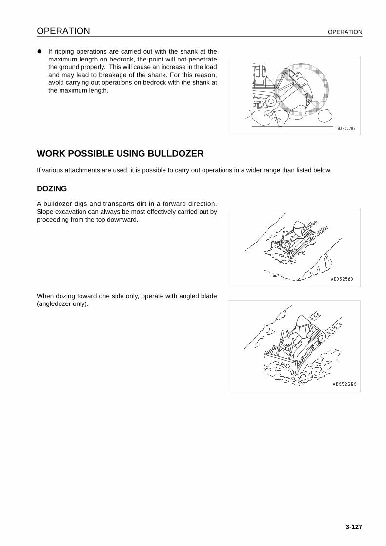
OPERATION OPERATION
q If ripping operations are carried out with the shank at themaximum length on bedrock, the point will not penetratethe ground properly. This will cause an increase in the loadand may lead to breakage of the shank. For this reason,avoid carrying out operations on bedrock with the shank atthe maximum length.
WORK POSSIBLE USING BULLDOZER 3
If various attachments are used, it is possible to carry out operations in a wider range than listed below.
DOZING 3
A bulldozer digs and transports dirt in a forward direction.Slope excavation can always be most effectively carried out byproceeding from the top downward.
When dozing toward one side only, operate with angled blade(angledozer only).
3-127
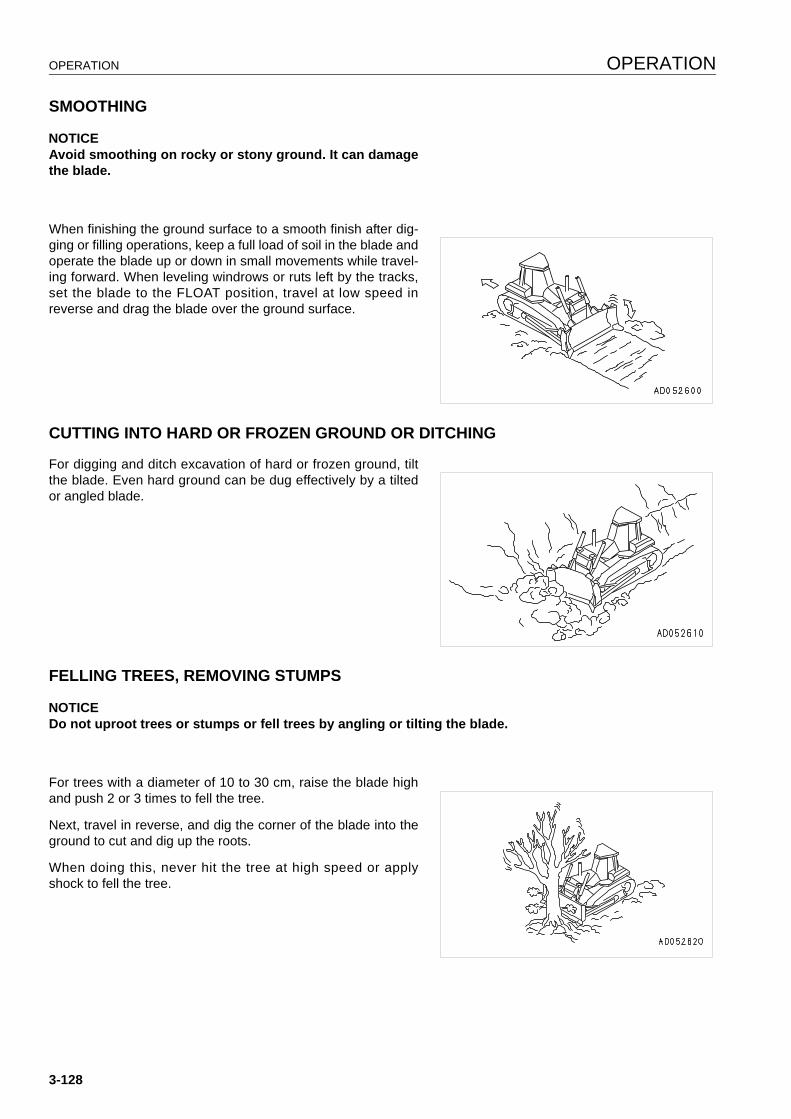
OPERATION OPERATION
SMOOTHING 3
NOTICEAvoid smoothing on rocky or stony ground. It can damagethe blade.
When finishing the ground surface to a smooth finish after dig-ging or filling operations, keep a full load of soil in the blade andoperate the blade up or down in small movements while travel-ing forward. When leveling windrows or ruts left by the tracks,set the blade to the FLOAT position, travel at low speed inreverse and drag the blade over the ground surface.
CUTTING INTO HARD OR FROZEN GROUND OR DITCHING 3
For digging and ditch excavation of hard or frozen ground, tiltthe blade. Even hard ground can be dug effectively by a tiltedor angled blade.
FELLING TREES, REMOVING STUMPS 3
NOTICEDo not uproot trees or stumps or fell trees by angling or tilting the blade.
For trees with a diameter of 10 to 30 cm, raise the blade highand push 2 or 3 times to fell the tree.
Next, travel in reverse, and dig the corner of the blade into theground to cut and dig up the roots.
When doing this, never hit the tree at high speed or applyshock to fell the tree.
3-128
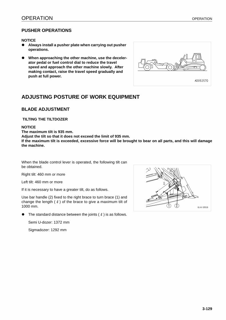
OPERATION OPERATION
PUSHER OPERATIONS 3
NOTICEq Always install a pusher plate when carrying out pusher
operations.
q When approaching the other machine, use the deceler-ator pedal or fuel control dial to reduce the travel speed and approach the other machine slowly. After making contact, raise the travel speed gradually and push at full power.
ADJUSTING POSTURE OF WORK EQUIPMENT 3
BLADE ADJUSTMENT 3
TILTING THE TILTDOZER
NOTICEThe maximum tilt is 935 mm.Adjust the tilt so that it does not exceed the limit of 935 mm.If the maximum tilt is exceeded, excessive force will be brought to bear on all parts, and this will damagethe machine.
When the blade control lever is operated, the following tilt canbe obtained.
Right tilt: 460 mm or more
Left tilt: 460 mm or more
If it is necessary to have a greater tilt, do as follows.
Use bar handle (2) fixed to the right brace to turn brace (1) andchange the length ( l ) of the brace to give a maximum tilt of1000 mm.
q The standard distance between the joints ( l ) is as follows.
Semi U-dozer: 1372 mm
Sigmadozer: 1292 mm
3-129

OPERATION OPERATION
ADJUSTING SHIM IN BLADE CYLINDER CAP
Set the standard shim adjustment in the blade cylinder cap to 4mm.
Remove shims to balance the wear of the cap and the ball atthe end of the piston rod.
The proper clearance to be maintained with the shims is 0.2 to0.5 mm.
ADJUSTING BRACE
WARNINGIf maintenance is carried out with the engine running,always have one worker sitting in the operator's seat whileanother worker carries out the maintenance. Both workersmust mutually confirm the safety during the operation.
Start the engine and use inching control to tilt to the left andright. Adjustment can be carried out easily by rotating the bracehandle while raising and lowering.
q When shortening brace (a)
It is easy to carry out the adjustment if the blade is set on top ofa block and the brace handle is turned.
REMARKWhen operated in this way, the blade is tilted, so the handle gradually becomes heavier. When this happens,return the blade from the tilt position to the horizontal position and turn the handle again according to the proce-dure given above.
SHIM ADJUSTMENT
Adjust with shims so that the play in the axial direction (direc-tion of the arrow) at the ball joints (3 places) is within 1 mm.
3-130
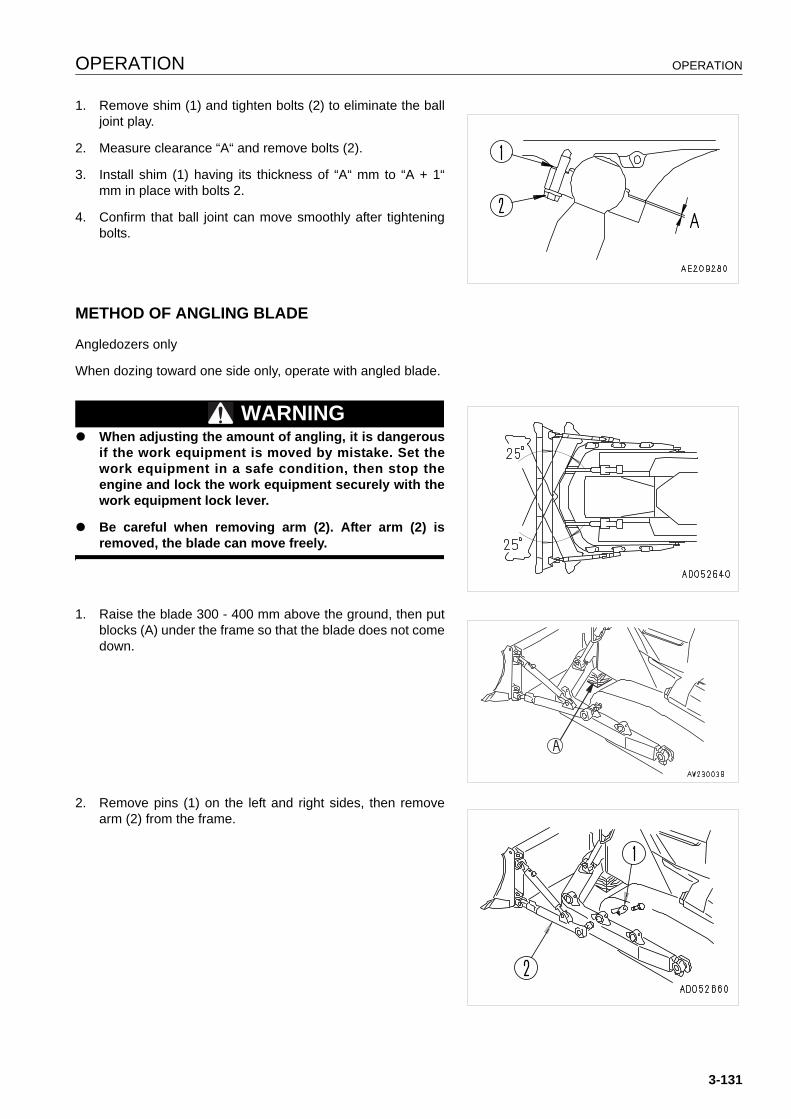
OPERATION OPERATION
1. Remove shim (1) and tighten bolts (2) to eliminate the balljoint play.
2. Measure clearance “A“ and remove bolts (2).
3. Install shim (1) having its thickness of “A“ mm to “A + 1“mm in place with bolts 2.
4. Confirm that ball joint can move smoothly after tighteningbolts.
METHOD OF ANGLING BLADE 3
Angledozers only
When dozing toward one side only, operate with angled blade.
WARNINGq When adjusting the amount of angling, it is dangerous
if the work equipment is moved by mistake. Set thework equipment in a safe condition, then stop theengine and lock the work equipment securely with thework equipment lock lever.
q Be careful when removing arm (2). After arm (2) isremoved, the blade can move freely.
1. Raise the blade 300 - 400 mm above the ground, then putblocks (A) under the frame so that the blade does not comedown.
2. Remove pins (1) on the left and right sides, then removearm (2) from the frame.
3-131
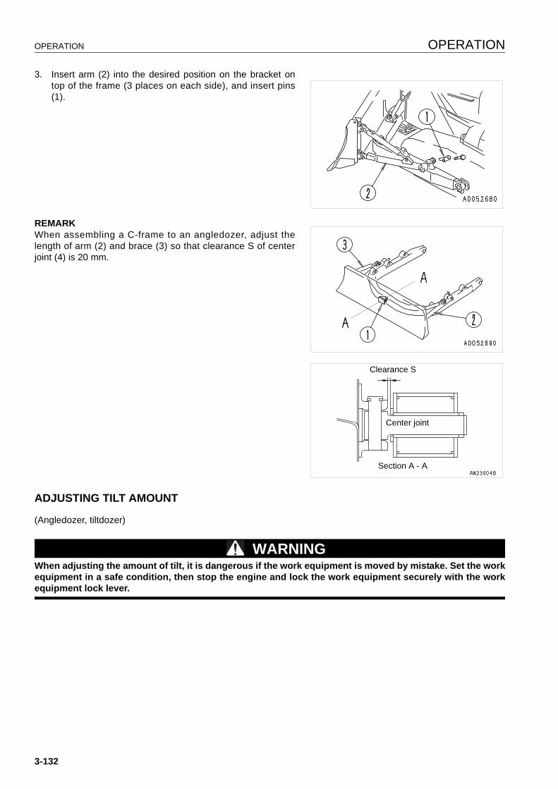
OPERATION OPERATION
3. Insert arm (2) into the desired position on the bracket ontop of the frame (3 places on each side), and insert pins(1).
REMARKWhen assembling a C-frame to an angledozer, adjust thelength of arm (2) and brace (3) so that clearance S of centerjoint (4) is 20 mm.
ADJUSTING TILT AMOUNT 3
(Angledozer, tiltdozer)
WARNINGWhen adjusting the amount of tilt, it is dangerous if the work equipment is moved by mistake. Set the workequipment in a safe condition, then stop the engine and lock the work equipment securely with the workequipment lock lever.
Clearance S
Center joint
Section A - A
3-132
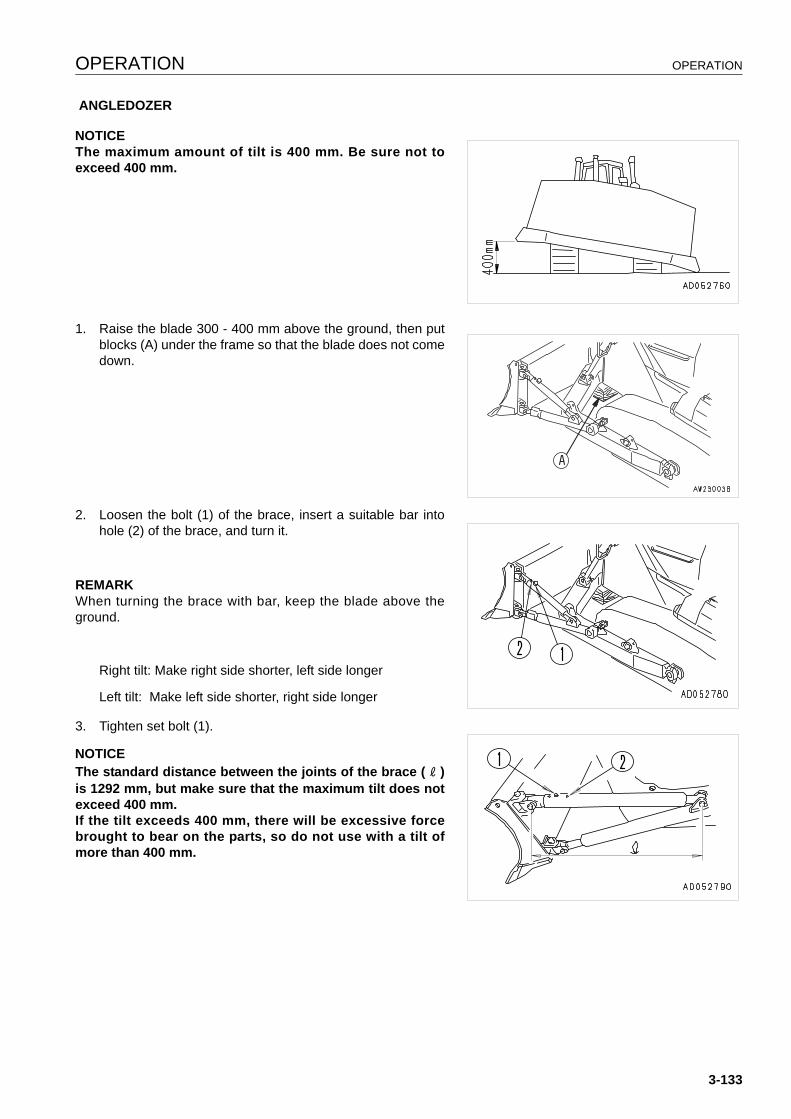
OPERATION OPERATION
ANGLEDOZER
NOTICEThe maximum amount of tilt is 400 mm. Be sure not toexceed 400 mm.
1. Raise the blade 300 - 400 mm above the ground, then putblocks (A) under the frame so that the blade does not comedown.
2. Loosen the bolt (1) of the brace, insert a suitable bar intohole (2) of the brace, and turn it.
REMARKWhen turning the brace with bar, keep the blade above theground.
Right tilt: Make right side shorter, left side longer
Left tilt: Make left side shorter, right side longer
3. Tighten set bolt (1).
NOTICEThe standard distance between the joints of the brace ( l )is 1292 mm, but make sure that the maximum tilt does notexceed 400 mm.If the tilt exceeds 400 mm, there will be excessive forcebrought to bear on the parts, so do not use with a tilt ofmore than 400 mm.
3-133
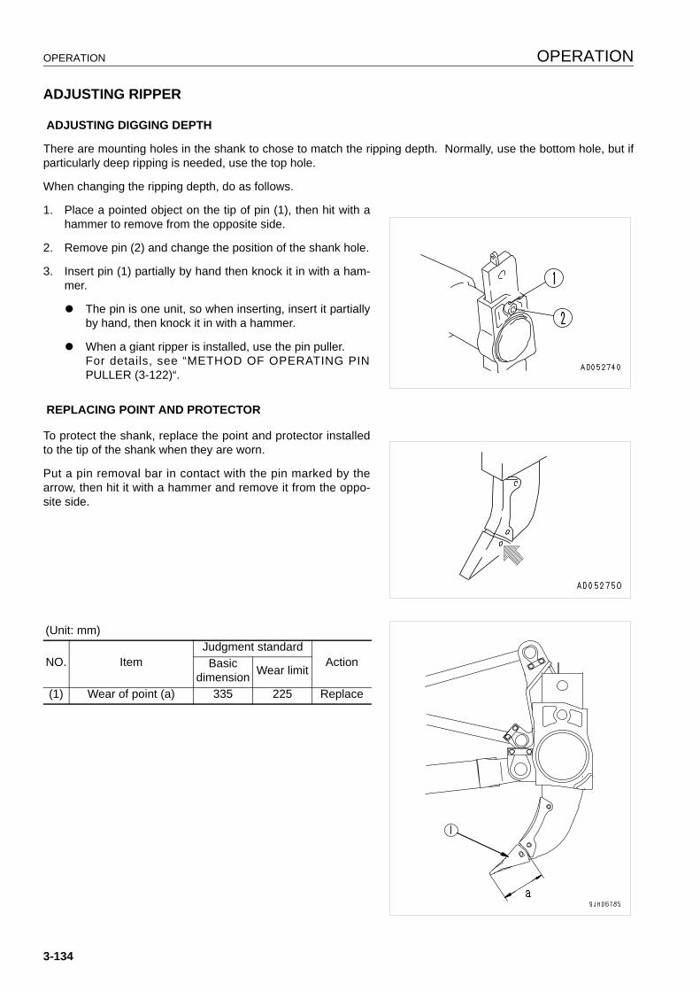
OPERATION OPERATION
ADJUSTING RIPPER 3
ADJUSTING DIGGING DEPTH
There are mounting holes in the shank to chose to match the ripping depth. Normally, use the bottom hole, but ifparticularly deep ripping is needed, use the top hole.
When changing the ripping depth, do as follows.
1. Place a pointed object on the tip of pin (1), then hit with ahammer to remove from the opposite side.
2. Remove pin (2) and change the position of the shank hole.
3. Insert pin (1) partially by hand then knock it in with a ham-mer.
q The pin is one unit, so when inserting, insert it partiallyby hand, then knock it in with a hammer.
q When a giant ripper is installed, use the pin puller.For details, see “METHOD OF OPERATING PINPULLER (3-122)“.
REPLACING POINT AND PROTECTOR
To protect the shank, replace the point and protector installedto the tip of the shank when they are worn.
Put a pin removal bar in contact with the pin marked by thearrow, then hit it with a hammer and remove it from the oppo-site side.
(Unit: mm)
NO. ItemJudgment standard
ActionBasic dimension Wear limit
(1) Wear of point (a) 335 225 Replace
3-134

OPERATION OPERATION
ADJUST ANGLE OF BLADE EDGE 3
(Angledozer, tiltdozer)
WARNINGIt is dangerous if the work equipment moves by mistake when adjusting angle of the blade edge. Set thework equipment in a stable condition, then stop the engine and lock the work equipment securely with thework equipment lock lever.
Adjust the angle (θ) of the blade edge to match the type of soil.
ANGLEDOZER
To make the length of the left and right braces the same,change distance ( l ) between the joints and adjust the cuttingangle.
Adjust distance ( l ) between the joints as follows:
To INCREASE distance ( l ), INCREASE cutting angle (θ).
To DECREASE distance ( l ), DECREASE cutting angle (θ).
The standard cutting angle (θ) is 54°.
The standard distance (l) between the joints is 1292 mm.
SEMI U-DOZER
Turn the brace with bar handle (1) and the distance ( l )between the joints to change the cutting angle (θ) as follows.
INCREASE distance ( l ) to INCREASE angle (θ)
DECREASE distance ( l ) to DECREASE angle (θ).
The standard cutting angle (θ) is 52°.
The standard distance (l) between the joints is 1372 mm.
SIGMADOZER
Turn the brace with bar handle (1) and the distance ( l )between the joints to change the cutting angle (θ) as follows.
INCREASE distance ( l ) to INCREASE angle (θ)
DECREASE distance ( l ) to DECREASE angle (θ).
The standard cutting angle (θ) is 46°.
The standard distance (l) between the joints is 1292 mm.
3-135
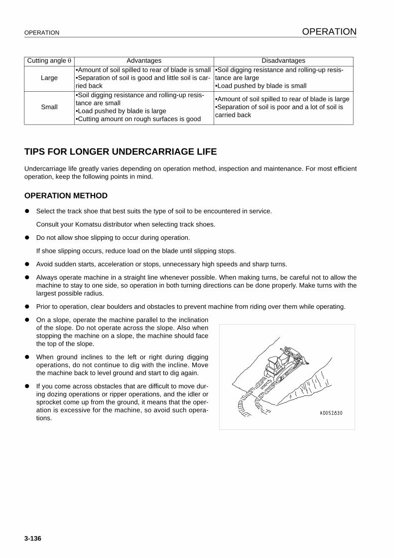
OPERATION OPERATION
TIPS FOR LONGER UNDERCARRIAGE LIFE 3
Undercarriage life greatly varies depending on operation method, inspection and maintenance. For most efficientoperation, keep the following points in mind.
OPERATION METHOD 3
q Select the track shoe that best suits the type of soil to be encountered in service.
Consult your Komatsu distributor when selecting track shoes.
q Do not allow shoe slipping to occur during operation.
If shoe slipping occurs, reduce load on the blade until slipping stops.
q Avoid sudden starts, acceleration or stops, unnecessary high speeds and sharp turns.
q Always operate machine in a straight line whenever possible. When making turns, be careful not to allow themachine to stay to one side, so operation in both turning directions can be done properly. Make turns with thelargest possible radius.
q Prior to operation, clear boulders and obstacles to prevent machine from riding over them while operating.
q On a slope, operate the machine parallel to the inclinationof the slope. Do not operate across the slope. Also whenstopping the machine on a slope, the machine should facethe top of the slope.
q When ground inclines to the left or right during diggingoperations, do not continue to dig with the incline. Movethe machine back to level ground and start to dig again.
q If you come across obstacles that are difficult to move dur-ing dozing operations or ripper operations, and the idler orsprocket come up from the ground, it means that the oper-ation is excessive for the machine, so avoid such opera-tions.
Cutting angle θ Advantages Disadvantages
Large•Amount of soil spilled to rear of blade is small•Separation of soil is good and little soil is car-ried back
•Soil digging resistance and rolling-up resis-tance are large•Load pushed by blade is small
Small
•Soil digging resistance and rolling-up resis-tance are small•Load pushed by blade is large•Cutting amount on rough surfaces is good
•Amount of soil spilled to rear of blade is large•Separation of soil is poor and a lot of soil is carried back
3-136

OPERATION OPERATION
INSPECTION AND ADJUSTING 3
q Adjust the track shoe to the proper tension.
When adjusting the tension, measure clearance (A)between the idler and carrier roller in the diagram on theright. The normal clearance is 20 to 30 mm, but on bed-rock, set the tension slightly higher, and on viscous ground,set it slightly looser.
(Inspect and adjust the track tension. For details of themethod of inspection and maintenance for the track ten-sion, see “WHEN REQUIRED (4-20)“.
q Check idler rollers for oil leakage as well as for loose boltsand nuts. If any trouble is detected, repair immediately.
q Check clearance (B) between the idler guide plate (1) andtrack frame. If clearance (B) becomes larger, the idler willmove to the side and cause the track shoe to come off. Fordetails of the method of inspection and maintenance, see“ADJUST IDLER CLEARANCE (4-33)“.
INSPECTION AND REPAIR 3
Frequent inspection and prompt repair will reduce repair costs.
The following items for inspection will serve as a guide to maintenance service of each undercarriage part. Per-form periodical inspection and contact the Komatsu distributor in your area when machine has approached repair-able limits and reversing limits.
MEASURING LINK PITCH
1. Insert a wooden block between track shoe and sprocket totake up the slack in track shoes.
2. Measure pitch length of 4 links in stretched portion at least2 links away for master pin. Of length obtained, 1/4 is thelink pitch.
3-137
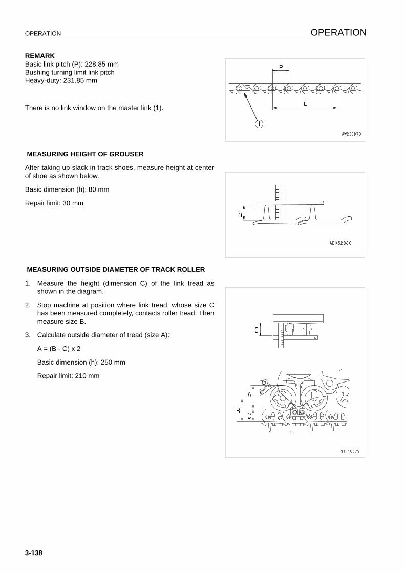
OPERATION OPERATION
REMARKBasic link pitch (P): 228.85 mmBushing turning limit link pitchHeavy-duty: 231.85 mm
There is no link window on the master link (1).
MEASURING HEIGHT OF GROUSER
After taking up slack in track shoes, measure height at centerof shoe as shown below.
Basic dimension (h): 80 mm
Repair limit: 30 mm
MEASURING OUTSIDE DIAMETER OF TRACK ROLLER
1. Measure the height (dimension C) of the link tread asshown in the diagram.
2. Stop machine at position where link tread, whose size Chas been measured completely, contacts roller tread. Thenmeasure size B.
3. Calculate outside diameter of tread (size A):
A = (B - C) x 2
Basic dimension (h): 250 mm
Repair limit: 210 mm
3-138
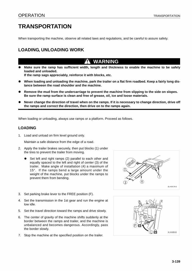
OPERATION TRANSPORTATION
TRANSPORTATION 3
When transporting the machine, observe all related laws and regulations, and be careful to assure safety.
LOADING, UNLOADING WORK 3
WARNINGq Make sure the ramp has sufficient width, length and thickness to enable the machine to be safely
loaded and unloaded.If the ramp sags appreciably, reinforce it with blocks, etc.
q When loading and unloading the machine, park the trailer on a flat firm roadbed. Keep a fairly long dis-tance between the road shoulder and the machine.
q Remove the mud from the undercarriage to prevent the machine from slipping to the side on slopes.Be sure the ramp surface is clean and free of grease, oil, ice and loose materials.
q Never change the direction of travel when on the ramps. If it is necessary to change direction, drive offthe ramps and correct the direction, then drive on to the ramps again.
When loading or unloading, always use ramps or a platform. Proceed as follows.
LOADING 3
1. Load and unload on firm level ground only.
Maintain a safe distance from the edge of a road.
2. Apply the trailer brakes securely, then put blocks (1) underthe tires to prevent the trailer from moving.
q Set left and right ramps (2) parallel to each other andequally spaced to the left and right of center (3) of thetrailer. Make angle of installation (4) a maximum of15°. If the ramps bend a large amount under theweight of the machine, put blocks under the ramps toprevent them from bending.
3. Set parking brake lever to the FREE position (F).
4. Set the transmission in the 1st gear and run the engine atlow idle.
5. Set the travel direction toward the ramps and drive slowly.
6. The center of gravity of the machine shifts suddenly at theborder between the ramps and trailer, and the machine isunbalanced and becomes dangerous. Accordingly, passthe border slowly.
7. Stop the machine at the specified position on the trailer.
3-139
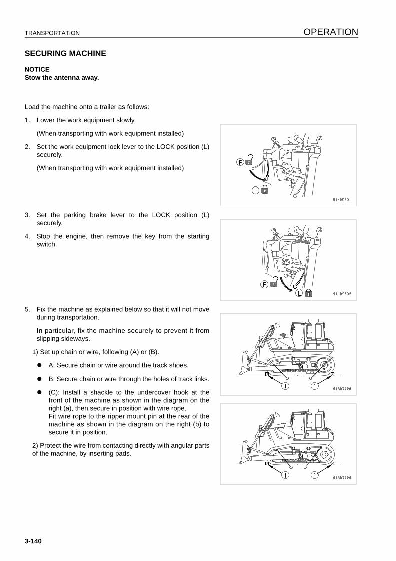
TRANSPORTATION OPERATION
SECURING MACHINE 3
NOTICEStow the antenna away.
Load the machine onto a trailer as follows:
1. Lower the work equipment slowly.
(When transporting with work equipment installed)
2. Set the work equipment lock lever to the LOCK position (L)securely.
(When transporting with work equipment installed)
3. Set the parking brake lever to the LOCK position (L)securely.
4. Stop the engine, then remove the key from the startingswitch.
5. Fix the machine as explained below so that it will not moveduring transportation.
In particular, fix the machine securely to prevent it fromslipping sideways.
1) Set up chain or wire, following (A) or (B).
q A: Secure chain or wire around the track shoes.
q B: Secure chain or wire through the holes of track links.
q (C): Install a shackle to the undercover hook at thefront of the machine as shown in the diagram on theright (a), then secure in position with wire rope.Fit wire rope to the ripper mount pin at the rear of themachine as shown in the diagram on the right (b) tosecure it in position.
2) Protect the wire from contacting directly with angular partsof the machine, by inserting pads.
3-140
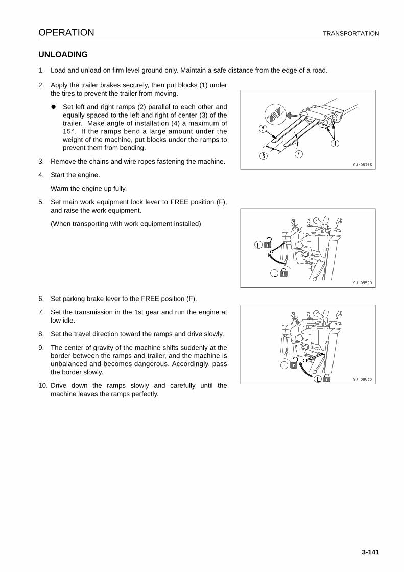
OPERATION TRANSPORTATION
UNLOADING 3
1. Load and unload on firm level ground only. Maintain a safe distance from the edge of a road.
2. Apply the trailer brakes securely, then put blocks (1) underthe tires to prevent the trailer from moving.
q Set left and right ramps (2) parallel to each other andequally spaced to the left and right of center (3) of thetrailer. Make angle of installation (4) a maximum of15°. If the ramps bend a large amount under theweight of the machine, put blocks under the ramps toprevent them from bending.
3. Remove the chains and wire ropes fastening the machine.
4. Start the engine.
Warm the engine up fully.
5. Set main work equipment lock lever to FREE position (F),and raise the work equipment.
(When transporting with work equipment installed)
6. Set parking brake lever to the FREE position (F).
7. Set the transmission in the 1st gear and run the engine atlow idle.
8. Set the travel direction toward the ramps and drive slowly.
9. The center of gravity of the machine shifts suddenly at theborder between the ramps and trailer, and the machine isunbalanced and becomes dangerous. Accordingly, passthe border slowly.
10. Drive down the ramps slowly and carefully until themachine leaves the ramps perfectly.
3-141
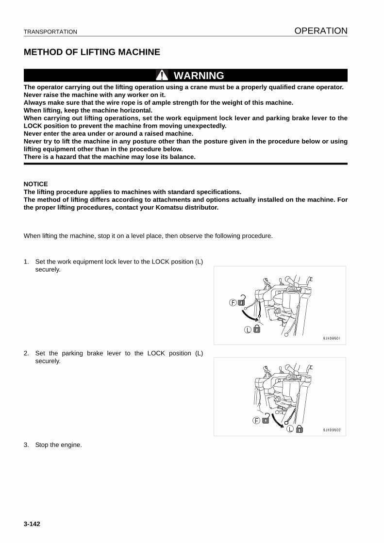
TRANSPORTATION OPERATION
METHOD OF LIFTING MACHINE 3
WARNINGThe operator carrying out the lifting operation using a crane must be a properly qualified crane operator.Never raise the machine with any worker on it.Always make sure that the wire rope is of ample strength for the weight of this machine.When lifting, keep the machine horizontal.When carrying out lifting operations, set the work equipment lock lever and parking brake lever to theLOCK position to prevent the machine from moving unexpectedly.Never enter the area under or around a raised machine.Never try to lift the machine in any posture other than the posture given in the procedure below or usinglifting equipment other than in the procedure below.There is a hazard that the machine may lose its balance.
NOTICEThe lifting procedure applies to machines with standard specifications.The method of lifting differs according to attachments and options actually installed on the machine. Forthe proper lifting procedures, contact your Komatsu distributor.
When lifting the machine, stop it on a level place, then observe the following procedure.
1. Set the work equipment lock lever to the LOCK position (L)securely.
2. Set the parking brake lever to the LOCK position (L)securely.
3. Stop the engine.
3-142
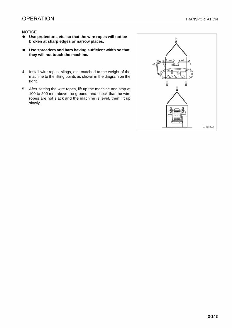
OPERATION TRANSPORTATION
NOTICEq Use protectors, etc. so that the wire ropes will not be
broken at sharp edges or narrow places.
q Use spreaders and bars having sufficient width so that they will not touch the machine.
4. Install wire ropes, slings, etc. matched to the weight of themachine to the lifting points as shown in the diagram on theright.
5. After setting the wire ropes, lift up the machine and stop at100 to 200 mm above the ground, and check that the wireropes are not slack and the machine is level, then lift upslowly.
3-143
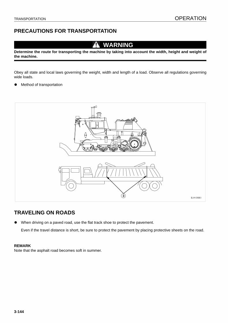
TRANSPORTATION OPERATION
PRECAUTIONS FOR TRANSPORTATION 3
WARNINGDetermine the route for transporting the machine by taking into account the width, height and weight ofthe machine.
Obey all state and local laws governing the weight, width and length of a load. Observe all regulations governingwide loads.
q Method of transportation
TRAVELING ON ROADS 3
q When driving on a paved road, use the flat track shoe to protect the pavement.
Even if the travel distance is short, be sure to protect the pavement by placing protective sheets on the road.
REMARKNote that the asphalt road becomes soft in summer.
3-144
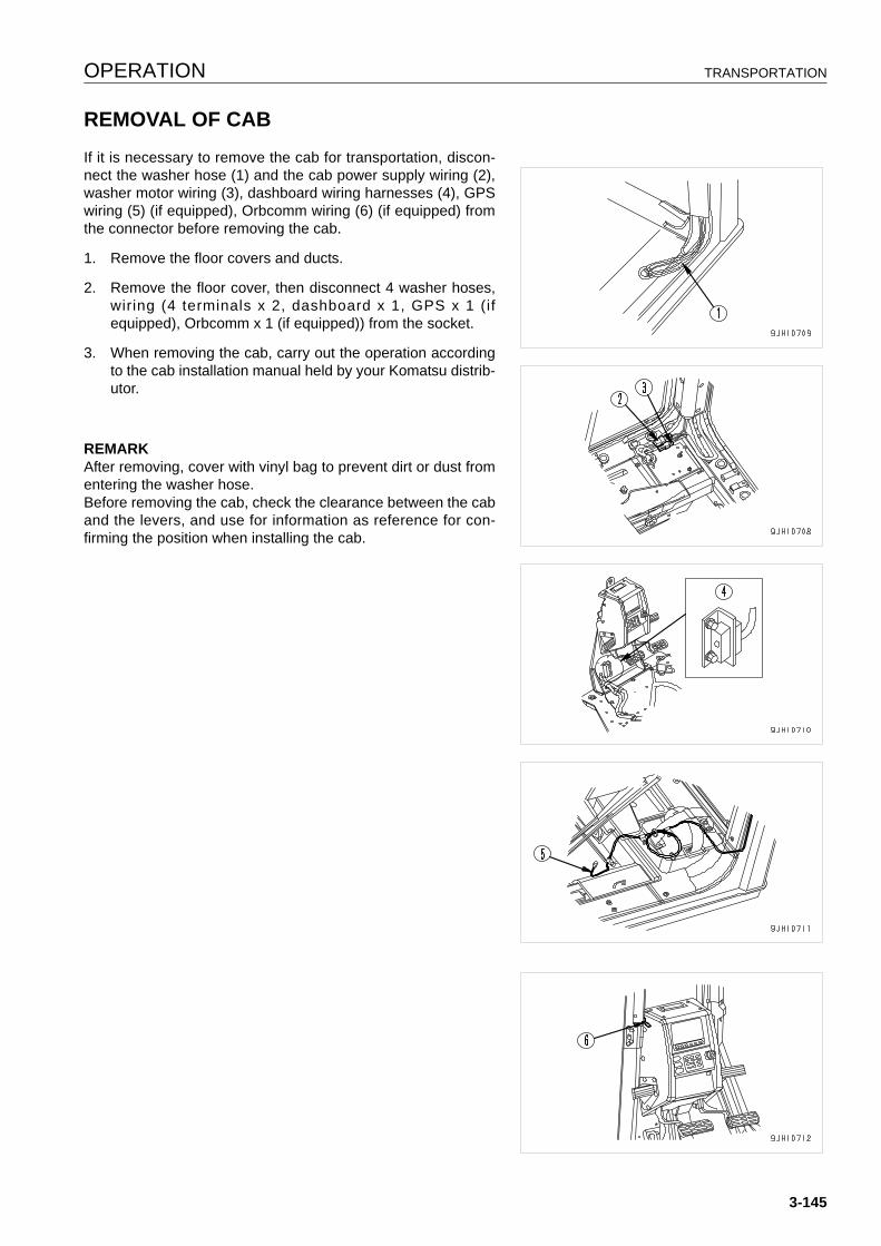
OPERATION TRANSPORTATION
REMOVAL OF CAB 3
If it is necessary to remove the cab for transportation, discon-nect the washer hose (1) and the cab power supply wiring (2),washer motor wiring (3), dashboard wiring harnesses (4), GPSwiring (5) (if equipped), Orbcomm wiring (6) (if equipped) fromthe connector before removing the cab.
1. Remove the floor covers and ducts.
2. Remove the floor cover, then disconnect 4 washer hoses,wiring (4 terminals x 2, dashboard x 1, GPS x 1 (ifequipped), Orbcomm x 1 (if equipped)) from the socket.
3. When removing the cab, carry out the operation accordingto the cab installation manual held by your Komatsu distrib-utor.
REMARKAfter removing, cover with vinyl bag to prevent dirt or dust fromentering the washer hose.Before removing the cab, check the clearance between the caband the levers, and use for information as reference for con-firming the position when installing the cab.
3-145
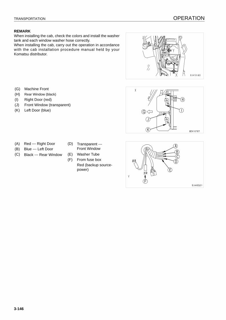
TRANSPORTATION OPERATION
REMARKWhen installing the cab, check the colors and install the washertank and each window washer hose correctly.When installing the cab, carry out the operation in accordancewith the cab installation procedure manual held by yourKomatsu distributor.
(G) Machine Front(H) Rear Window (black)(I) Right Door (red)(J) Front Window (transparent)(K) Left Door (blue)
(A) Red --- Right Door (D) Transparent --- Front Window(B) Blue --- Left Door
(C) Black --- Rear Window (E) Washer Tube(F) From fuse box
Red (backup source-power)
3-146
OPERATION COLD WEATHER OPERATION
COLD WEATHER OPERATION 3
PRECAUTIONS FOR LOW TEMPERATURE 3
If the temperature becomes low, it becomes difficult to start the engine, and the coolant may freeze, so do as fol-lows.
FUEL AND LUBRICANTS 3
Change to oil with low viscosity for all components. For details of the specified visicosity, see “RECOMMENDEDFUEL, COOLANT, AND LUBRICANT (4-12)“.
COOLANT 3
WARNINGq Antifreeze coolant is toxic. Be careful not to get it into your eyes or on your skin. If it should get into
your eyes or on your skin, wash it off with large quantities of fresh water and see a doctor at once.
q Antifreeze coolant is toxic. Be extremely careful when handling it. When replacing coolant containingantifreeze or when handling coolant when repairing the radiator, contact your Komatsu distributor orask your local antifreeze dealer. Be careful not to let the water flow into drainage ditches or spray on tothe ground surface.
q Antifreeze coolant is flammable, so do not bring any flame close. Do not smoke when handling anti-freeze.
NOTICEq Use Komatsu Supercoolant (AF-NAC) wherever available, or use permanent type antifreeze coolant.
q Never use methanol, ethanol, or propanol-based antifreeze.
q Do not use any water leakage prevention agent, either alone, or in combination with antifreeze.
q Do not mix one brand of antifreeze with a different brand.
q When using Komatsu super coolant (AF-NAC), there is no need to use a corrosion resistor. For details, see “CLEAN INSIDE OF COOLING SYSTEM (4-20)“.
For details on the amount of antifreeze mixture and on when to change the coolant, see “CLEAN INSIDE OFCOOLING SYSTEM (4-20)“.
3-147
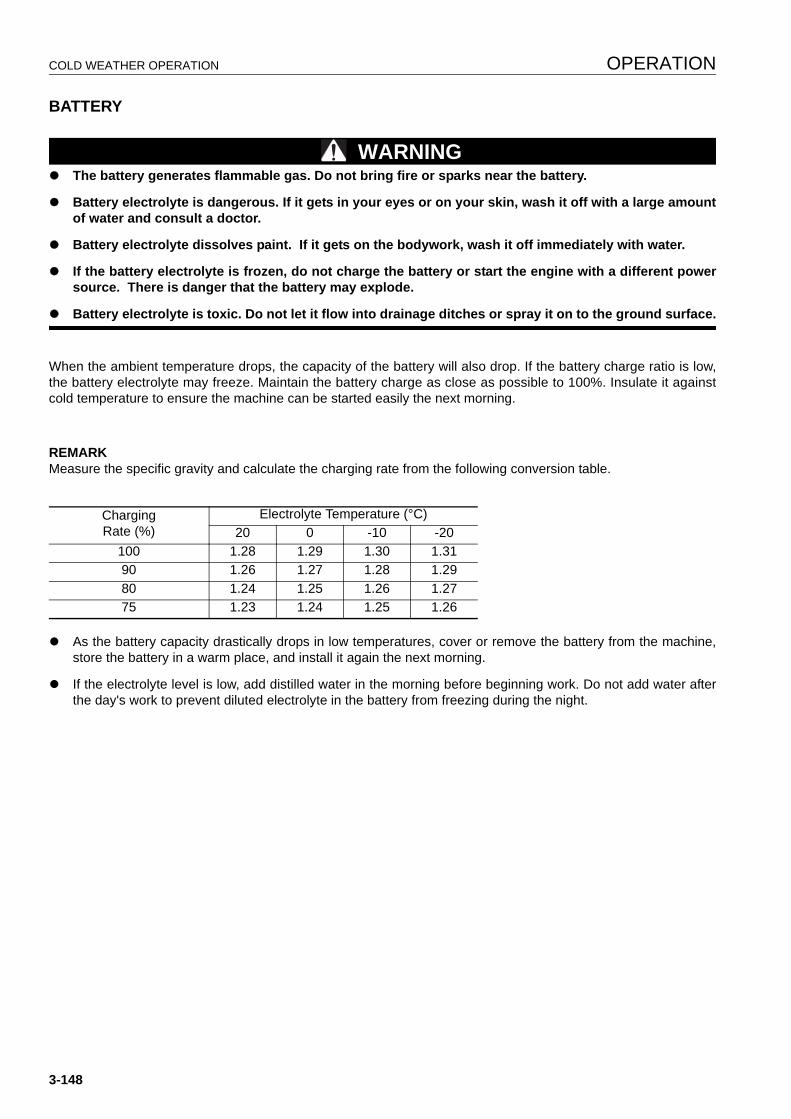
COLD WEATHER OPERATION OPERATION
BATTERY 3
WARNINGq The battery generates flammable gas. Do not bring fire or sparks near the battery.
q Battery electrolyte is dangerous. If it gets in your eyes or on your skin, wash it off with a large amountof water and consult a doctor.
q Battery electrolyte dissolves paint. If it gets on the bodywork, wash it off immediately with water.
q If the battery electrolyte is frozen, do not charge the battery or start the engine with a different powersource. There is danger that the battery may explode.
q Battery electrolyte is toxic. Do not let it flow into drainage ditches or spray it on to the ground surface.
When the ambient temperature drops, the capacity of the battery will also drop. If the battery charge ratio is low,the battery electrolyte may freeze. Maintain the battery charge as close as possible to 100%. Insulate it againstcold temperature to ensure the machine can be started easily the next morning.
REMARKMeasure the specific gravity and calculate the charging rate from the following conversion table.
q As the battery capacity drastically drops in low temperatures, cover or remove the battery from the machine,store the battery in a warm place, and install it again the next morning.
q If the electrolyte level is low, add distilled water in the morning before beginning work. Do not add water afterthe day's work to prevent diluted electrolyte in the battery from freezing during the night.
ChargingRate (%)
Electrolyte Temperature (°C)20 0 -10 -20
100 1.28 1.29 1.30 1.3190 1.26 1.27 1.28 1.2980 1.24 1.25 1.26 1.2775 1.23 1.24 1.25 1.26
3-148
OPERATION COLD WEATHER OPERATION
AFTER COMPLETION OF WORK 3
WARNINGPerforming idle-running of the tracks is dangerous, stay well away from the tracks.
To prevent mud, water, or the undercarriage from freezing and making it impossible for the machine to move onthe following morning, observe the following precautions.
q Remove all the mud and water from the machine body. In particular, wipe the hydraulic cylinder rods clean toprevent damage to the seal caused by mud, dirt, or drops of water on the rod from getting inside the seal.
q Park the machine on hard, dry ground.
If this is impossible, park the machine on boards.
The boards prevent the tracks from freezing to the ground, and allow the machine to be moved the next morn-ing.
q Open the drain valve and drain any water collected in the fuel system to prevent it from freezing.
q After operation in water or mud, remove water from undercarriage as described below to extend undercarriageservice life.
1. Swing 90° with engine at low idle and bring the work equipment to the side of the track.
2. Jack up the machine until the track is raised slightly from the ground. Rotate the track under no load. Repeatthis procedure on both the left and right sides.
AFTER COLD WEATHER 3
When the season changes and the weather becomes warmer, do as follows.
q Replace the fuel and oil for all parts with oil of the viscosity specified.
For details, see “RECOMMENDED FUEL, COOLANT, AND LUBRICANT (4-12)“.
3-149
LONG-TERM STORAGE OPERATION
LONG-TERM STORAGE 3
BEFORE STORAGE 3
When putting the machine in storage for a long time (more than one month), do as follows.
q Clean and wash all parts, then store the machine indoors. If the machine has to be stored outdoors, selectlevel ground and cover the machine with canvas.
q Completely fill the fuel tank. This prevents moisture from collecting.
q Lubricate and change the oil before storage.
q Apply a thin coat of grease to metal surface of the hydraulic piston rods and the idler adjusting rods.
q Disconnect the negative terminals of the battery and cover it, or remove it from the machine and store it sepa-rately.
q Place all control levers at the neutral position, set the work equipment lock lever and parking lever to the lockposition, and set the fuel control dial to the low idling position.
q To prevent rust, fill with Komatsu genuine super coolant to give a density of at least 30% for the engine cool-ant.
DURING STORAGE 3
WARNINGIf it is necessary to perform the rust-prevention operation while the machine is indoors, open the doorsand windows to improve ventilation and prevent gas poisoning.
q During storage, operate and move the machine for a short distance once a month so that a new film of oil willcoat moving parts. At the same time, also charge the battery.
q For machines equipped with an air conditioner, run the air conditioner.
AFTER STORAGE 3
NOTICEIf the machine has been stored without carrying out the monthly rust-prevention operation, consult yourKomatsu distributor before using it.
When using the machine after long-term storage, do as follows before using it.
q Wipe off the grease from the hydraulic cylinder rods.
q Add oil and grease at all lubrication points.
q When the machine is stored for a long period, moisture in the air will mix with the oil. Check the oil before andafter starting the engine. If there is water in the oil, change all the oil.
3-150
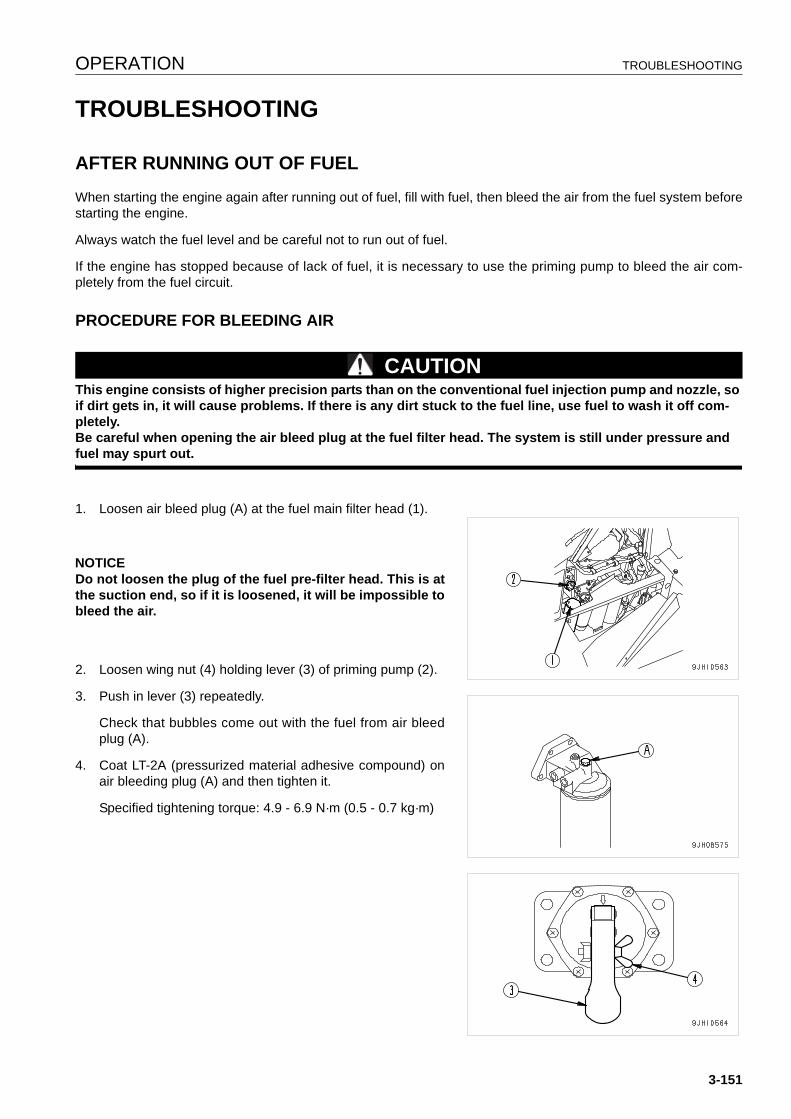
OPERATION TROUBLESHOOTING
TROUBLESHOOTING 3
AFTER RUNNING OUT OF FUEL 3
When starting the engine again after running out of fuel, fill with fuel, then bleed the air from the fuel system beforestarting the engine.
Always watch the fuel level and be careful not to run out of fuel.
If the engine has stopped because of lack of fuel, it is necessary to use the priming pump to bleed the air com-pletely from the fuel circuit.
PROCEDURE FOR BLEEDING AIR 3
CAUTIONThis engine consists of higher precision parts than on the conventional fuel injection pump and nozzle, so if dirt gets in, it will cause problems. If there is any dirt stuck to the fuel line, use fuel to wash it off com-pletely.Be careful when opening the air bleed plug at the fuel filter head. The system is still under pressure and fuel may spurt out.
1. Loosen air bleed plug (A) at the fuel main filter head (1).
NOTICEDo not loosen the plug of the fuel pre-filter head. This is atthe suction end, so if it is loosened, it will be impossible tobleed the air.
2. Loosen wing nut (4) holding lever (3) of priming pump (2).
3. Push in lever (3) repeatedly.
Check that bubbles come out with the fuel from air bleedplug (A).
4. Coat LT-2A (pressurized material adhesive compound) onair bleeding plug (A) and then tighten it.
Specified tightening torque: 4.9 - 6.9 N·m (0.5 - 0.7 kg·m)
3-151
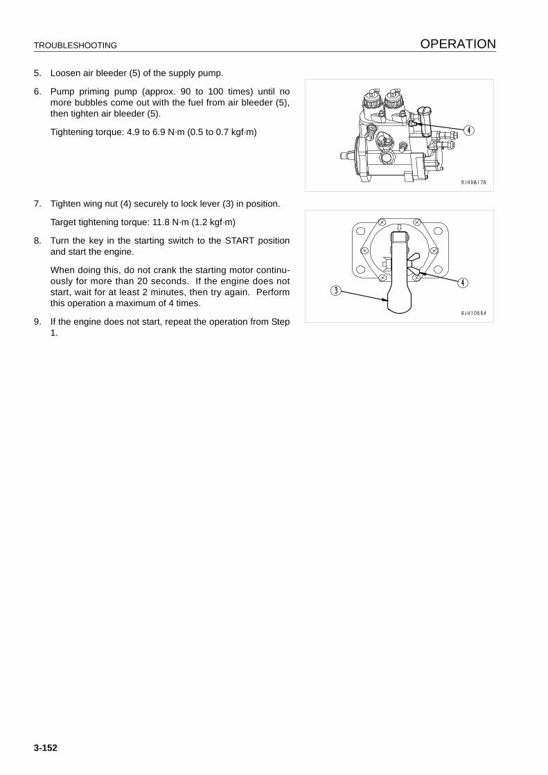
TROUBLESHOOTING OPERATION
5. Loosen air bleeder (5) of the supply pump.
6. Pump priming pump (approx. 90 to 100 times) until nomore bubbles come out with the fuel from air bleeder (5),then tighten air bleeder (5).
Tightening torque: 4.9 to 6.9 N·m (0.5 to 0.7 kgf·m)
7. Tighten wing nut (4) securely to lock lever (3) in position.
Target tightening torque: 11.8 N·m (1.2 kgf·m)
8. Turn the key in the starting switch to the START positionand start the engine.
When doing this, do not crank the starting motor continu-ously for more than 20 seconds. If the engine does notstart, wait for at least 2 minutes, then try again. Performthis operation a maximum of 4 times.
9. If the engine does not start, repeat the operation from Step1.
3-152
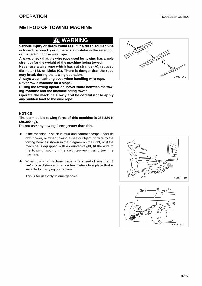
OPERATION TROUBLESHOOTING
METHOD OF TOWING MACHINE 3
WARNINGSerious injury or death could result if a disabled machineis towed incorrectly or if there is a mistake in the selectionor inspection of the wire rope.Always check that the wire rope used for towing has amplestrength for the weight of the machine being towed.Never use a wire rope which has cut strands (A), reduceddiameter (B), or kinks (C). There is danger that the ropemay break during the towing operation.Always wear leather gloves when handling wire rope.Never tow a machine on a slope.During the towing operation, never stand between the tow-ing machine and the machine being towed.Operate the machine slowly and be careful not to applyany sudden load to the wire rope.
NOTICEThe permissible towing force of this machine is 287,330 N(29,300 kg).Do not use any towing force greater than this.
q If the machine is stuck in mud and cannot escape under itsown power, or when towing a heavy object, fit wire to thetowing hook as shown in the diagram on the right, or if themachine is equipped with a counterweight, fit the wire tothe towing hook on the counterweight and tow themachine.
q When towing a machine, travel at a speed of less than 1km/h for a distance of only a few meters to a place that issuitable for carrying out repairs.
This is for use only in emergencies.
3-153
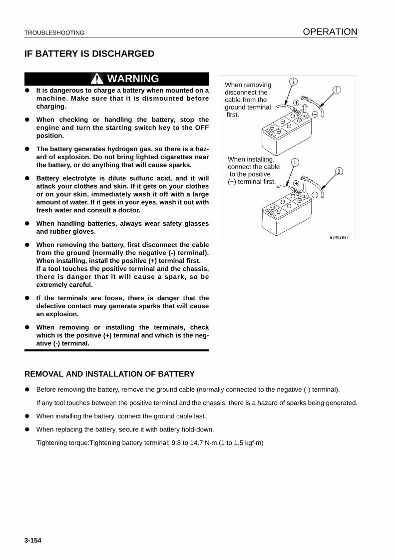
TROUBLESHOOTING OPERATION
IF BATTERY IS DISCHARGED 3
WARNINGq It is dangerous to charge a battery when mounted on a
machine. Make sure that it is dismounted beforecharging.
q When checking or handling the battery, stop theengine and turn the starting switch key to the OFFposition.
q The battery generates hydrogen gas, so there is a haz-ard of explosion. Do not bring lighted cigarettes nearthe battery, or do anything that will cause sparks.
q Battery electrolyte is dilute sulfuric acid, and it willattack your clothes and skin. If it gets on your clothesor on your skin, immediately wash it off with a largeamount of water. If it gets in your eyes, wash it out withfresh water and consult a doctor.
q When handling batteries, always wear safety glassesand rubber gloves.
q When removing the battery, first disconnect the cablefrom the ground (normally the negative (-) terminal).When installing, install the positive (+) terminal first.If a tool touches the positive terminal and the chassis,there is danger that it will cause a spark, so beextremely careful.
q If the terminals are loose, there is danger that thedefective contact may generate sparks that will causean explosion.
q When removing or installing the terminals, checkwhich is the positive (+) terminal and which is the neg-ative (-) terminal.
REMOVAL AND INSTALLATION OF BATTERY 3
q Before removing the battery, remove the ground cable (normally connected to the negative (-) terminal).
If any tool touches between the positive terminal and the chassis, there is a hazard of sparks being generated.
q When installing the battery, connect the ground cable last.
q When replacing the battery, secure it with battery hold-down.
Tightening torque:Tightening battery terminal: 9.8 to 14.7 N·m (1 to 1.5 kgf·m)
When removingdisconnect thecable from the ground terminal first.
When installing, connect the cable to the positive (+) terminal first.
3-154
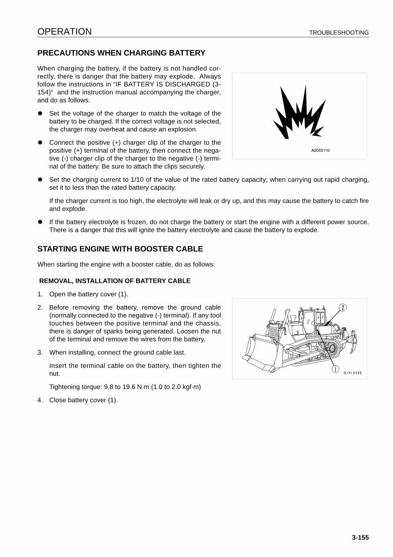
OPERATION TROUBLESHOOTING
PRECAUTIONS WHEN CHARGING BATTERY 3
When charging the battery, if the battery is not handled cor-rectly, there is danger that the battery may explode. Alwaysfollow the instructions in “IF BATTERY IS DISCHARGED (3-154)“ and the instruction manual accompanying the charger,and do as follows.
q Set the voltage of the charger to match the voltage of thebattery to be charged. If the correct voltage is not selected,the charger may overheat and cause an explosion.
q Connect the positive (+) charger clip of the charger to thepositive (+) terminal of the battery, then connect the nega-tive (-) charger clip of the charger to the negative (-) termi-nal of the battery. Be sure to attach the clips securely.
q Set the charging current to 1/10 of the value of the rated battery capacity; when carrying out rapid charging,set it to less than the rated battery capacity.
If the charger current is too high, the electrolyte will leak or dry up, and this may cause the battery to catch fireand explode.
q If the battery electrolyte is frozen, do not charge the battery or start the engine with a different power source.There is a danger that this will ignite the battery electrolyte and cause the battery to explode.
STARTING ENGINE WITH BOOSTER CABLE 3
When starting the engine with a booster cable, do as follows:
REMOVAL, INSTALLATION OF BATTERY CABLE
1. Open the battery cover (1).
2. Before removing the battery, remove the ground cable(normally connected to the negative (-) terminal). If any tooltouches between the positive terminal and the chassis,there is danger of sparks being generated. Loosen the nutof the terminal and remove the wires from the battery.
3. When installing, connect the ground cable last.
Insert the terminal cable on the battery, then tighten thenut.
Tightening torque: 9.8 to 19.6 N·m (1.0 to 2.0 kgf·m)
4. Close battery cover (1).
3-155
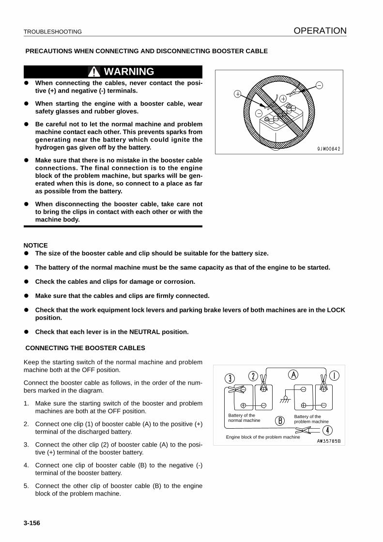
TROUBLESHOOTING OPERATION
PRECAUTIONS WHEN CONNECTING AND DISCONNECTING BOOSTER CABLE
WARNINGq When connecting the cables, never contact the posi-
tive (+) and negative (-) terminals.
q When starting the engine with a booster cable, wearsafety glasses and rubber gloves.
q Be careful not to let the normal machine and problemmachine contact each other. This prevents sparks fromgenerating near the battery which could ignite thehydrogen gas given off by the battery.
q Make sure that there is no mistake in the booster cableconnections. The final connection is to the engineblock of the problem machine, but sparks will be gen-erated when this is done, so connect to a place as faras possible from the battery.
q When disconnecting the booster cable, take care notto bring the clips in contact with each other or with themachine body.
NOTICEq The size of the booster cable and clip should be suitable for the battery size.
q The battery of the normal machine must be the same capacity as that of the engine to be started.
q Check the cables and clips for damage or corrosion.
q Make sure that the cables and clips are firmly connected.
q Check that the work equipment lock levers and parking brake levers of both machines are in the LOCK position.
q Check that each lever is in the NEUTRAL position.
CONNECTING THE BOOSTER CABLES
Keep the starting switch of the normal machine and problemmachine both at the OFF position.
Connect the booster cable as follows, in the order of the num-bers marked in the diagram.
1. Make sure the starting switch of the booster and problemmachines are both at the OFF position.
2. Connect one clip (1) of booster cable (A) to the positive (+)terminal of the discharged battery.
3. Connect the other clip (2) of booster cable (A) to the posi-tive (+) terminal of the booster battery.
4. Connect one clip of booster cable (B) to the negative (-)terminal of the booster battery.
5. Connect the other clip of booster cable (B) to the engineblock of the problem machine.
Battery of thenormal machine
Battery of the problem machine
Engine block of the problem machine
3-156

OPERATION TROUBLESHOOTING
STARTING THE ENGINE
1. Make sure the clips are firmly connected to the battery terminals.
2. Start the engine of the booster machine and keep it running at high idling speed.
3. Turn the starting switch of problem machine to the START position, and start the engine. If the engine doesn'tstart at first, try it again after 2 minutes.
DISCONNECTING THE BOOSTER CABLES
After the engine has started, disconnect booster cables in thereverse order in which they were connected.
1. Remove clip of booster cable (B) from the engine block ofproblem machine.
2. Remove clip of booster cable (B) from negative (-) terminalof the booster battery.
3. Remove clip of booster cable (A) from the positive (+) ter-minal of booster battery.
4. Remove clip (4) of booster cable (A) from positive (+) ter-minal of the discharged battery.
Battery of the normal machine
Battery of the problem machine
Engine block of theproblem machine
3-157
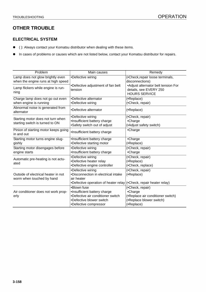
TROUBLESHOOTING OPERATION
OTHER TROUBLE 3
ELECTRICAL SYSTEM 3
q ( ): Always contact your Komatsu distributor when dealing with these items.
q In cases of problems or causes which are not listed below, contact your Komatsu distributor for repairs.
Problem Main causes RemedyLamp does not glow brightly even when the engine runs at high speed
•Defective wiring
•Defective adjustment of fan belt tension
(•Check,repair loose terminals, disconnections) •Adjust alternator belt tension For details, see EVERY 250 HOURS SERVICE
Lamp flickers while engine is run-ning
Charge lamp does not go out even when engine is running
•Defective alternator•Defective wiring
(•Replace)(•Check, repair)
Abnormal noise is generated from alternator •Defective alternator (•Replace)
Starting motor does not turn when starting switch is turned to ON
•Defective wiring•Insufficient battery charge•Safety switch out of adjust
(•Check, repair) •Charge(•Adjust safety switch)
Pinion of starting motor keeps going in and out •Insufficient battery charge •Charge
Starting motor turns engine slug-gishly
•Insufficient battery charge•Defective starting motor
•Charge(•Replace)
Starting motor disengages before engine starts
•Defective wiring•Insufficient battery charge
(•Check, repair) •Charge
Automatic pre-heating is not actu-ated
•Defective wiring•Defective heater relay•Defective engine controller
(•Check, repair)(•Replace)(•Check, replace)
Outside of electrical heater in not worm when touched by hand
•Defective wiring•Disconnection in electrical intake air heater•Defective operation of heater relay
(•Check, repair)(•Replace)
(•Check, repair heater relay)
Air conditioner does not work prop-erly
•Blown fuse•Insufficient battery charge•Defective air conditioner switch•Defective blower switch•Defective compressor
(•Check, repair) •Charge(•Replace air conditioner switch)(•Replace blower switch)(•Replace)
3-158
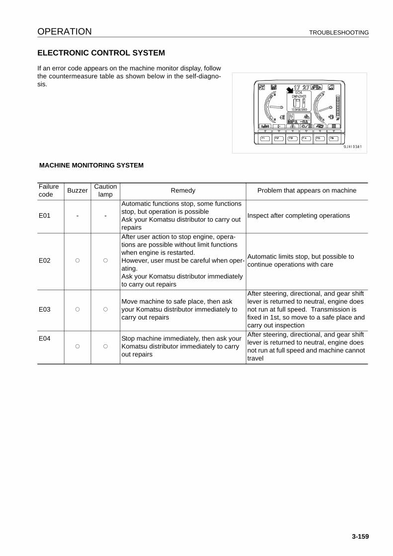
OPERATION TROUBLESHOOTING
ELECTRONIC CONTROL SYSTEM 3
If an error code appears on the machine monitor display, followthe countermeasure table as shown below in the self-diagno-sis.
MACHINE MONITORING SYSTEM
Failure code Buzzer Caution
lamp Remedy Problem that appears on machine
E01 - -
Automatic functions stop, some functions stop, but operation is possibleAsk your Komatsu distributor to carry out repairs
Inspect after completing operations
E02 Q Q
After user action to stop engine, opera-tions are possible without limit functions when engine is restarted.However, user must be careful when oper-ating.Ask your Komatsu distributor immediately to carry out repairs
Automatic limits stop, but possible to continue operations with care
E03 Q QMove machine to safe place, then ask your Komatsu distributor immediately to carry out repairs
After steering, directional, and gear shift lever is returned to neutral, engine does not run at full speed. Transmission is fixed in 1st, so move to a safe place and carry out inspection
E04Q Q
Stop machine immediately, then ask your Komatsu distributor immediately to carry out repairs
After steering, directional, and gear shift lever is returned to neutral, engine does not run at full speed and machine cannot travel
3-159
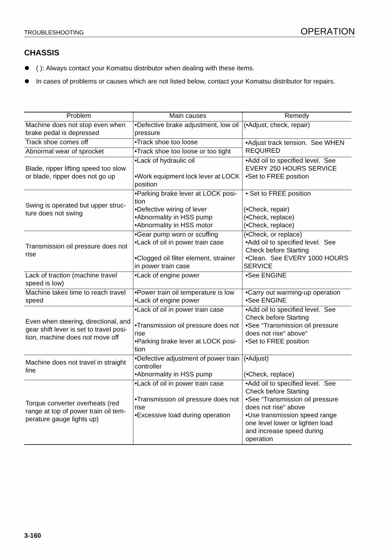
TROUBLESHOOTING OPERATION
CHASSIS 3
q ( ): Always contact your Komatsu distributor when dealing with these items.
q In cases of problems or causes which are not listed below, contact your Komatsu distributor for repairs.
Problem Main causes RemedyMachine does not stop even when brake pedal is depressed
•Defective brake adjustment, low oil pressure
(•Adjust, check, repair)
Track shoe comes off •Track shoe too loose •Adjust track tension. See WHEN REQUIREDAbnormal wear of sprocket •Track shoe too loose or too tight
Blade, ripper lifting speed too slow or blade, ripper does not go up
•Lack of hydraulic oil
•Work equipment lock lever at LOCK position
•Add oil to specified level. See EVERY 250 HOURS SERVICE •Set to FREE position
Swing is operated but upper struc-ture does not swing
•Parking brake lever at LOCK posi-tion•Defective wiring of lever•Abnormality in HSS pump•Abnormality in HSS motor
• Set to FREE position
(•Check, repair)(•Check, replace)(•Check, replace)
Transmission oil pressure does not rise
•Gear pump worn or scuffing•Lack of oil in power train case
•Clogged oil filter element, strainer in power train case
(•Check, or replace) •Add oil to specified level. See Check before Starting •Clean. See EVERY 1000 HOURS SERVICE
Lack of traction (machine travel speed is low)
•Lack of engine power •See ENGINE
Machine takes time to reach travel speed
•Power train oil temperature is low•Lack of engine power
•Carry out warming-up operation •See ENGINE
Even when steering, directional, and gear shift lever is set to travel posi-tion, machine does not move off
•Lack of oil in power train case
•Transmission oil pressure does not rise•Parking brake lever at LOCK posi-tion
•Add oil to specified level. See Check before Starting •See “Transmission oil pressure does not rise“ above“ •Set to FREE position
Machine does not travel in straight line
•Defective adjustment of power train controller•Abnormality in HSS pump
(•Adjust)
(•Check, replace)
Torque converter overheats (red range at top of power train oil tem-perature gauge lights up)
•Lack of oil in power train case
•Transmission oil pressure does not rise•Excessive load during operation
•Add oil to specified level. See Check before Starting •See “Transmission oil pressure does not rise“ above •Use transmission speed range one level lower or lighten load and increase speed during operation
3-160
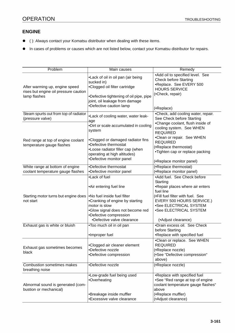
OPERATION TROUBLESHOOTING
ENGINE 3
q ( ): Always contact your Komatsu distributor when dealing with these items.
q In cases of problems or causes which are not listed below, contact your Komatsu distributor for repairs.
Problem Main causes Remedy
After warming up, engine speed rises but engine oil pressure caution lamp flashes
•Lack of oil in oil pan (air being sucked in)•Clogged oil filter cartridge
•Defective tightening of oil pipe, pipe joint, oil leakage from damage•Defective caution lamp
•Add oil to specified level. See Check before Starting •Replace. See EVERY 500 HOURS SERVICE(•Check, repair)
(•Replace)Steam spurts out from top of radiator (pressure valve) •Lack of cooling water, water leak-
age•Dirt or scale accumulated in cooling system
•Clogged or damaged radiator fins •Defective thermostat•Loose radiator filler cap (when operating at high altitudes)•Defective monitor panel
•Check, add cooling water, repair. See Check before Starting •Change coolant, flush inside of cooling system. See WHEN REQUIRED •Clean or repair. See WHEN REQUIRED(•Replace thermostat) •Tighten cap or replace packing
(•Replace monitor panel)
Red range at top of engine coolant temperature gauge flashes
White range at bottom of engine coolant temperature gauge flashes
•Defective thermostat•Defective monitor panel
(•Replace thermostat)(•Replace monitor panel)
Starting motor turns but engine does not start
•Lack of fuel
•Air entering fuel line
•No fuel inside fuel filter•Cranking of engine by starting motor is slow•Glow signal does not become red•Defective compression •Defective valve clearance
•Add fuel. See Check before Starting •Repair places where air enters fuel line(•Fill fuel filter with fuel. See EVERY 500 HOURS SERVICE.) •See ELECTRICAL SYSTEM •See ELECTRICAL SYSTEM
(•Adjust clearance)Exhaust gas is white or bluish •Too much oil in oil pan
•Improper fuel
•Drain excess oil. See Check before Starting •Replace with specified fuel
Exhaust gas sometimes becomes black
•Clogged air cleaner element•Defective nozzle•Defective compression
•Clean or replace. See WHEN REQUIRED(•Replace nozzle)(•See “Defective compression“ above)
Combustion sometimes makes breathing noise
•Defective nozzle (•Replace nozzle)
Abnormal sound is generated (com-bustion or mechanical)
•Low-grade fuel being used•Overheating
•Breakage inside muffler•Excessive valve clearance
•Replace with specified fuel •See “Red range at top of engine coolant temperature gauge flashes“ above(•Replace muffler)(•Adjust clearance)
3-161

TROUBLESHOOTING OPERATION
POINT OF CONTACT TO TELEPHONE WHEN ERROR OCCURS 3
If an error screen is displayed on the monitor, the telephonenumber for the point of contact is displayed at the bottom of theerror screen.
REMARKIf no point of contact telephone number has been registered,no telephone number is displayed.It is necessary to register the telephone number, please askyour Komatsu distributor to carry out the registration.
Error code is displayed on monitor
Contact your Komatsu distributorAlarm buzzer soundsEngine suddenly lost power (entered delayed mode)
3-162

MAINTENANCE
14
WARNINGPlease read and make sure that you understand the SAFETYsection volume before reading this section.
GUIDES TO MAINTENANCE MAINTENANCE
GUIDES TO MAINTENANCE 4
Do not perform any inspection and maintenance operation that is not found in this manual.
Stop the machine on flat hard ground when performing inspections and maintenance.
CHECK SERVICE METER:
Check the service meter reading every day to see if the time has come for any necessary maintenance to be per-formed.
KOMATSU GENUINE REPLACEMENT PARTS:
Use Komatsu genuine parts specified in the Parts Book as replacement parts.
KOMATSU GENUINE OILS:
Use Komatsu genuine oils and grease. Choose oils and grease with proper viscosities specified for ambient tem-perature.
ALWAYS USE CLEAN WASHER FLUID:
Use automobile window washer fluid, and be careful not to let any dirt get into it.
CLEAN OIL AND GREASE:
Use clean oil and grease. Also, keep the containers of the oil and grease clean. Keep foreign materials away fromoil and grease.
CHECK FOREIGN MATERIAL IN DRAINED OIL:
After oil is changed or filters are replaced, check the old oil and filters for metal particles and foreign materials. Iflarge quantity of metal particles or foreign materials are found, always report to the person in charge, and carry outsuitable action.
FUEL STRAINER:
If your machine is equipped with a fuel strainer, do not remove it while fueling.
WELDING INSTRUCTIONS:
q Turn off the engine starting switch.
q Do not apply more than 200 V continuously.
q Connect grounding cable within 1 m of the area to be welded. If grounding cable is connected near instru-ments, connectors, etc., the instruments may malfunction.
q If a seal or bearing happens to come between the part being welded and grounding point, change the ground-ing point to avoid such parts.
q Do not use the area around the work equipment pins or the hydraulic cylinders as the grounding point.
OBJECTS IN YOUR POCKETS:
q When opening inspection windows or the oil filler port of the tank to carry out inspection, be careful not to dropnuts, bolts, or tools inside the machine.
If such things are dropped inside the machine, it may cause damage and/or malfunction of the machine, andwill lead to failure. If you drop anything inside the machine, always remove it immediately.
q Do not put unnecessary things in your pockets. Carry only things which are necessary for inspection.
4-2
MAINTENANCE GUIDES TO MAINTENANCE
DUSTY WORKSITES:
When working at dusty worksites, do as follows:
q Inspect the air cleaner clogging monitor frequently to see if the air cleaner is clogged.
Clean the air cleaner element at a shorter interval than specified.
q Clean the radiator core frequently to avoid clogging.
q Clean and replace the fuel filter frequently.
q Clean electrical components, especially the starting motor and alternator, to avoid accumulation of dust.
q When inspecting or changing the oil, move the machine to a place that is free of dust to prevent dirt from get-ting into the oil.
AVOID MIXING OILS:
If a different brand or grade of oil has to be added, drain the old oil and replace all the oil with the new brand orgrade of oil. Never mix different brand or grade of oil.
LOCKING INSPECTION COVERS:
Lock inspection cover securely into position with the lock bar. If inspection or maintenance is performed withinspection cover not locked in position, there is a danger that it may be suddenly blow shut by the wind and causeinjury to the worker.
BLEEDING AIR:
When hydraulic equipment has been repaired or replaced, or the hydraulic piping has been removed and installedagain, the air must be bled from the circuit. For details, see “PROCEDURE FOR BLEEDING AIR FROMHYDRAULIC CIRCUIT (4-37)“.
PRECAUTIONS WHEN INSTALLING HYDRAULIC HOSES:
q When removing parts at locations where there are O-rings or gasket seals, clean the mounting surface, andreplace with new parts.
When doing this, be careful not to forget to assemble the O-rings and gaskets.
q When installing the hoses, do not twist them or bend them sharply. If they are installed so, their service life willbe shortened extremely and they may be damaged.
CHECKS AFTER INSPECTION AND MAINTENANCE:
If you forget to perform the checks after inspection and maintenance, unexpected problems may occur, and thismay lead to serious injury or property damage. Always do the following:
q Checks after operation (with engine stopped)
q Have any inspection and maintenance points been forgotten?
q Have all inspection and maintenance items been performed correctly?
q Have any tools or parts been dropped inside the machine? It is particularly dangerous if parts are droppedinside the machine and get caught in the lever linkage mechanism.
q Are there any leakage of coolant or oil? Have all nuts and bolts been tightened?
q Checks when operating engine
q For details of the checks when operating the engine, see “PROPER TOOLS (2-29)“ and pay careful atten-tion to safety.
q Are the inspection and maintenance items working properly?
q Is there any leakage of fuel or oil when the engine speed is raised?
4-3

GUIDES TO MAINTENANCE MAINTENANCE
PRECAUTIONS WHEN OPENING AND CLOSING ENGINE SIDE COVER:
q When standing on track to open the engine side cover,adopt a standing position, hold the side cover with boththumbs, and open it slowly with your other fingers.
q When the side cover is open, do not open or close the cab.
Before opening or closing the cab, always close the engineside
cover first.
Except, however, when the hydraulic driving fan is in thereverse rotation mode.
4-4
MAINTENANCE OUTLINES OF SERVICE
OUTLINES OF SERVICE 4
q Always use Komatsu genuine parts for replacement parts, grease or oil.
q When changing the oil or adding oil, do not mix different types of oil. When changing the type of oil, drain allthe old oil and fill completely with the new oil. Always replace the filter at the same time. (There is no problemif the small amount of oil remaining in the piping mixes with the new oil.)
q Unless there is any specific request, the oil, fuel, and coolant used on the machine when it is shipped from thefactory are as shown in the table below.
HANDLING OIL, FUEL, COOLANT, AND PERFORMING OIL CLINIC 4
OIL 4
q Oil is used for the engine and hydraulic equipment under extremely severe conditions (high temperature, high-pressure), so the oil deteriorates with use.
Always refer to the Operation and Maintenance Manual and use the recommended oil that matches the grade(class) and maximum and minimum ambient temperatures.
Even if the oil does not appear to be dirty, always change it after the specified interval.
q Oil corresponds to blood in the human body, always be careful when handling it to prevent any impurities(water, metal particles, dirt, etc.) from getting in.
The majority of problems with the machine are caused by the entry of such impurities.
Take particular care not to let any impurities get in when storing or adding oil.
q Never mix oils of different grades or brands.
q Always add the specified amount of oil.
Having too much oil or too little oil are both causes of problems.
q If the oil in the work equipment is not clear, there is probably water or air getting into the circuit. In such cases,please contact your Komatsu distributor.
q When changing the oil, always replace the related filters at the same time.
q We recommend periodic performance of the oil clinic to ensure that you always know the condition of themachine. Please contact your Komatsu distributor for details of the oil clinic.
q When the machine is shipped from the factory,T010 (power train oil) is used for the hydraulic system.
When using H046-HM hydraulic oil, drain all the oil and fill with the specified amount of oil.
Always use oil recommended by Komatsu. If any other oil is used, it will cause clogging of the filter.
There is no problem if the new oil is mixed with the small amount of oil remaining in the piping and cylinders.
Item TypeEngine oil pan Engine oil 15W40DH (Komatsu genuine parts)Power train caseFinal drive caseDamper case
Power train oil TO30 (Komatsu genuine parts)
Hydraulic tank Power train oil T010 (Komatsu genuine parts)Radiator Supercoolant AF-NAC (Density: 30% or above) (Komatsu genuine parts)
4-5

OUTLINES OF SERVICE MAINTENANCE
FUEL 4
q To prevent the moisture in the air from condensing and forming water inside the fuel tank, always fill the fueltank after completing the day's work.
q The fuel pump is a precision instrument, and if fuel containing water or dirt is used, it cannot work properly.
q Be extremely careful not to let impurities get in when storing or adding fuel.
q Always use fuel that matches the temperatures given in the Operation and Maintenance Manual.
q If the fuel is used in temperatures lower than the specified temperature for use (particularly at tempera-tures of lower than -15°C), the properties of the fuel will make it congeal.
q If the fuel is used in temperatures higher than the specified temperature for use, the viscosity will go down,and this may result in a drop in output or other problems.
q Before starting the engine, or when 10 minutes have passed after adding fuel, drain the sediment and waterfrom the fuel tank.
q If the engine runs out of fuel, or if the filters have been replaced, it is necessary to bleed the air from the circuit.
NOTICEAlways use diesel oil for the fuel.To ensure good fuel consumption characteristics and exhaust gas characteristics, the engine mounted onthis machine uses an electronically controlled high-pressure fuel injection device. This device requireshigh precision parts and lubrication, so if low viscosity fuel with low lubricating ability is used, the durabil-ity may drop markedly.
COOLANT AND WATER FOR DILUTION 4
q The coolant is diluted for use, so always use distilled water or tap water (soft water) when diluting the coolant.Natural water, such as river water or well water (hard water), contains large amounts of minerals (calcium ormagnesium) and will cause scale to form inside the engine and the radiator. Once scale forms, it is difficult toremove, and it will cause deficient heat exchange, leading to overheating. To prevent this, we recommend theuse of water with a maximum overall hardness of 100 ppm (mg/ l ) when diluting the coolant.
q This machine is filled with Komatsu genuine super coolant (AF-NAC) at the factory. This super coolant has theimportant function of preventing corrosion in the cooling system as well as preventing freezing.
As a general rule, we do not recommend use of any coolant other than the Komatsu super coolant (AF-NAC).If any other coolant is used, it may cause serious problems with the engine and cooling system.
q Komatsu genuine super coolant can be used continuously for two years or 4000 hours.
q The undiluted coolant is flammable, so be particularly careful to keep it away from flame.
q The ratio of Supercoolant (AF-NAC) to water differs according to the ambient temperature.
For details of the ratio when mixing, see “RECOMMENDED FUEL, COOLANT, AND LUBRICANT (4-12)“.
q If the engine overheats, wait for the engine to cool before adding coolant.
q If the coolant level is low, it will cause overheating, and will also cause problems with corrosion due to airentering the coolant.
4-6
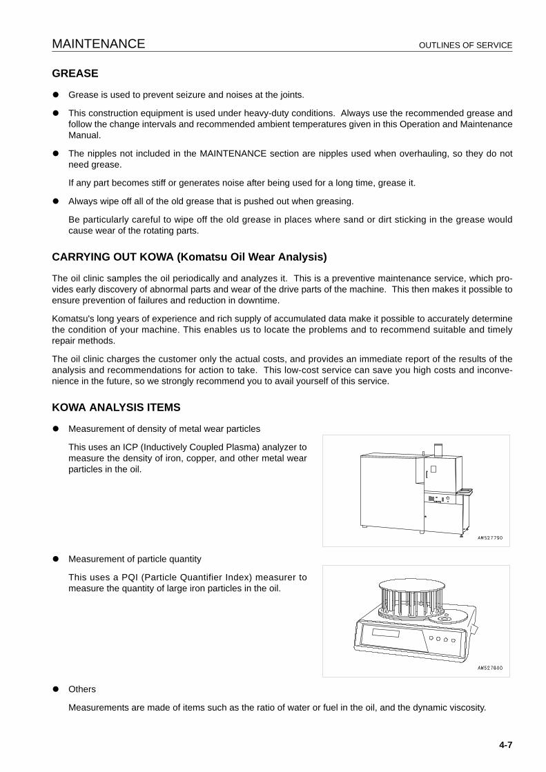
MAINTENANCE OUTLINES OF SERVICE
GREASE 4
q Grease is used to prevent seizure and noises at the joints.
q This construction equipment is used under heavy-duty conditions. Always use the recommended grease andfollow the change intervals and recommended ambient temperatures given in this Operation and MaintenanceManual.
q The nipples not included in the MAINTENANCE section are nipples used when overhauling, so they do notneed grease.
If any part becomes stiff or generates noise after being used for a long time, grease it.
q Always wipe off all of the old grease that is pushed out when greasing.
Be particularly careful to wipe off the old grease in places where sand or dirt sticking in the grease wouldcause wear of the rotating parts.
CARRYING OUT KOWA (Komatsu Oil Wear Analysis) 4
The oil clinic samples the oil periodically and analyzes it. This is a preventive maintenance service, which pro-vides early discovery of abnormal parts and wear of the drive parts of the machine. This then makes it possible toensure prevention of failures and reduction in downtime.
Komatsu's long years of experience and rich supply of accumulated data make it possible to accurately determinethe condition of your machine. This enables us to locate the problems and to recommend suitable and timelyrepair methods.
The oil clinic charges the customer only the actual costs, and provides an immediate report of the results of theanalysis and recommendations for action to take. This low-cost service can save you high costs and inconve-nience in the future, so we strongly recommend you to avail yourself of this service.
KOWA ANALYSIS ITEMS 4
q Measurement of density of metal wear particles
This uses an ICP (Inductively Coupled Plasma) analyzer tomeasure the density of iron, copper, and other metal wearparticles in the oil.
q Measurement of particle quantity
This uses a PQI (Particle Quantifier Index) measurer tomeasure the quantity of large iron particles in the oil.
q Others
Measurements are made of items such as the ratio of water or fuel in the oil, and the dynamic viscosity.
4-7
OUTLINES OF SERVICE MAINTENANCE
OIL SAMPLING 4
q Sampling interval
250 hours: Engine
500 hours: Other components
q Precautions when sampling
q Make sure that the oil is well mixed before sampling.
q Perform sampling at regular fixed intervals.
q Do not perform sampling on rainy or windy days when water or dust can get into the oil.
For further details of KOWA, please contact your Komatsu distributor.
STORING OIL AND FUEL 4
q Keep indoors to prevent any water, dirt, or other impurities from getting in.
q When keeping drum cans for a long period, put the drum on its side so that the filler port of the drums is at theside to prevent moisture from being sucked in.
If drums have to be stored outside, cover them with a waterproof sheet or take other measures to protectthem.
q To prevent any change in quality during long-term storage, be sure to use in the order of first in - first out (usethe oldest oil or fuel first).
FILTERS 4
q Filters are extremely important safety parts. They prevent impurities in the fuel and air circuits from enteringimportant equipment and causing problems.
Replace all filters periodically. For details, see the Operation and Maintenance Manual.
However, when working in severe conditions, replace the filters at shorter intervals according to the oil and fuel(sulfur content) being used.
q Never try to clean the filters (cartridge type) and use them again. Always replace with new filters.
q When replacing oil filters, check if any metal particles are attached to the old filter. If any metal particles arefound, contact your Komatsu distributor.
q Do not open packs of spare filters until just before they are to be used.
q Use of Komatsu genuine filter elements is strongly recommended.
OUTLINE OF ELECTRIC SYSTEM 4
q It is extremely dangerous if the electrical equipment becomes wet or the covering of the wiring is damaged.This will cause an electrical short circuit and may lead to malfunction of the machine. Do not wash the inside ofthe operator's cab with water. When washing the machine, be careful not to let water get into the electricalcomponents.
q Service relating to the electric system is checking fan belt tension, checking damage or wear to the fan beltand checking battery fluid level.
q Never install any electric components other than those specified by Komatsu.
4-8

MAINTENANCE OUTLINES OF SERVICE
q External electro-magnetic interference may cause malfunction of the control system controller, before install-ing a radio receiver or other wireless equipment, contact your Komatsu distributor.
q When working at the seashore, carefully clean the electric system to prevent corrosion.
q When installing electrical equipment, connect it to the special power source connector.
Do not connect the optional power source to the fuse, starting switch, or battery relay.
4-9
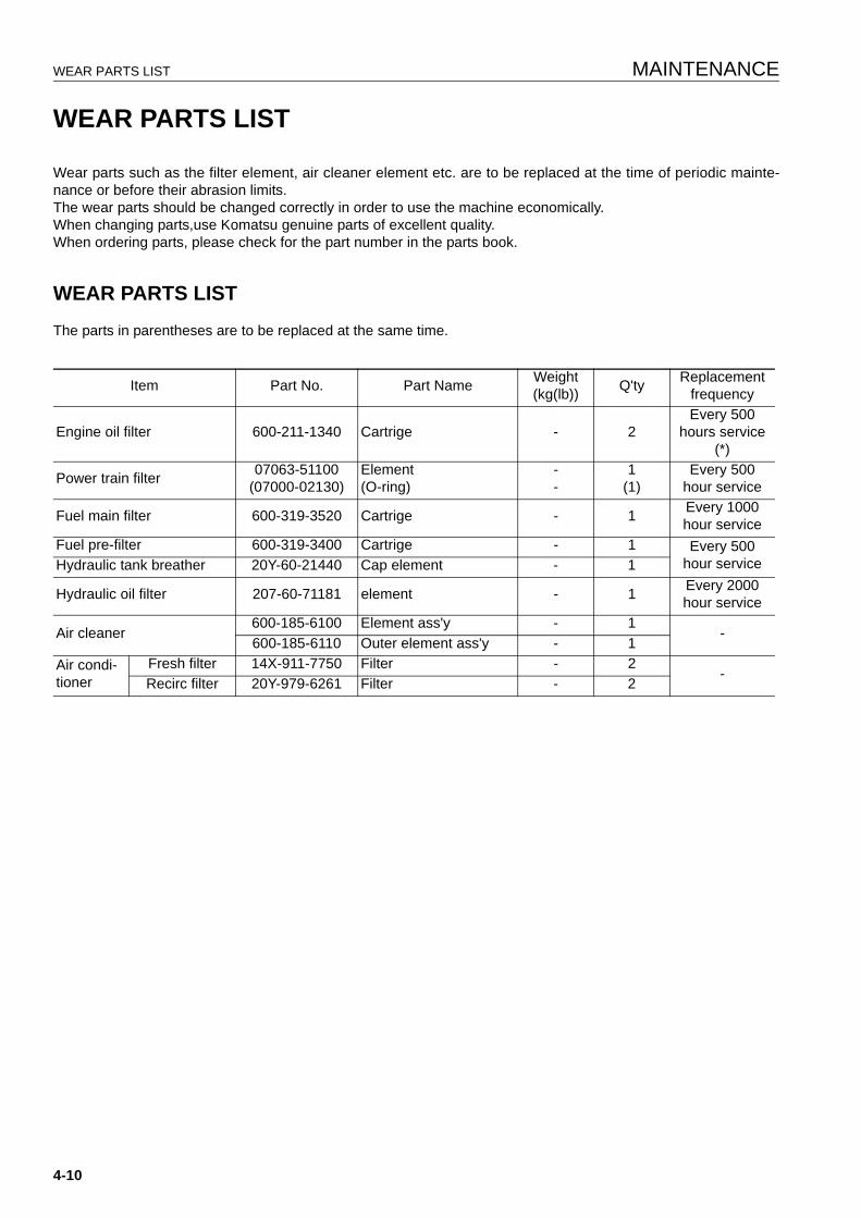
WEAR PARTS LIST MAINTENANCE
WEAR PARTS LIST 4
Wear parts such as the filter element, air cleaner element etc. are to be replaced at the time of periodic mainte-nance or before their abrasion limits.The wear parts should be changed correctly in order to use the machine economically.When changing parts,use Komatsu genuine parts of excellent quality.When ordering parts, please check for the part number in the parts book.
WEAR PARTS LIST 4
The parts in parentheses are to be replaced at the same time.
Item Part No. Part Name Weight(kg(lb)) Q'ty Replacement
frequency
Engine oil filter 600-211-1340 Cartrige - 2Every 500
hours service (*)
Power train filter 07063-51100(07000-02130)
Element(O-ring)
--
1(1)
Every 500hour service
Fuel main filter 600-319-3520 Cartrige - 1 Every 1000hour service
Fuel pre-filter 600-319-3400 Cartrige - 1 Every 500hour serviceHydraulic tank breather 20Y-60-21440 Cap element - 1
Hydraulic oil filter 207-60-71181 element - 1 Every 2000hour service
Air cleaner600-185-6100 Element ass'y - 1
-600-185-6110 Outer element ass'y - 1
Air condi-tioner
Fresh filter 14X-911-7750 Filter - 2-
Recirc filter 20Y-979-6261 Filter - 2
4-10
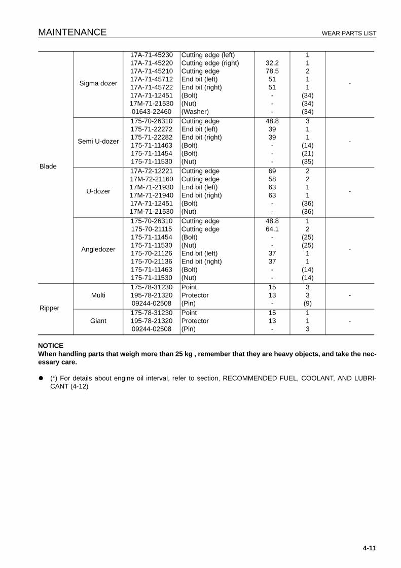
MAINTENANCE WEAR PARTS LIST
NOTICEWhen handling parts that weigh more than 25 kg , remember that they are heavy objects, and take the nec-essary care.
q (*) For details about engine oil interval, refer to section, RECOMMENDED FUEL, COOLANT, AND LUBRI-CANT (4-12)
Blade
Sigma dozer
17A-71-4523017A-71-4522017A-71-4521017A-71-4571217A-71-4572217A-71-1245117M-71-2153001643-22460
Cutting edge (left)Cutting edge (right)Cutting edgeEnd bit (left)End bit (right)(Bolt)(Nut)(Washer)
32.278.55151---
11211
(34)(34)(34)
-
Semi U-dozer
175-70-26310175-71-22272175-71-22282175-71-11463175-71-11454175-71-11530
Cutting edgeEnd bit (left)End bit (right)(Bolt)(Bolt)(Nut)
48.83939---
311
(14)(21)(35)
-
U-dozer
17A-72-1222117M-72-2116017M-71-2193017M-71-2194017A-71-1245117M-71-21530
Cutting edgeCutting edgeEnd bit (left)End bit (right)(Bolt)(Nut)
69586363--
2211
(36)(36)
-
Angledozer
175-70-26310175-70-21115175-71-11454175-71-11530175-70-21126175-70-21136175-71-11463175-71-11530
Cutting edgeCutting edge(Bolt)(Nut)End bit (left)End bit (right)(Bolt)(Nut)
48.864.1
--
3737--
12
(25)(25)
11
(14)(14)
-
Ripper
Multi175-78-31230195-78-2132009244-02508
PointProtector(Pin)
1513-
33
(9)-
Giant175-78-31230195-78-2132009244-02508
PointProtector(Pin)
1513-
113
-
4-11
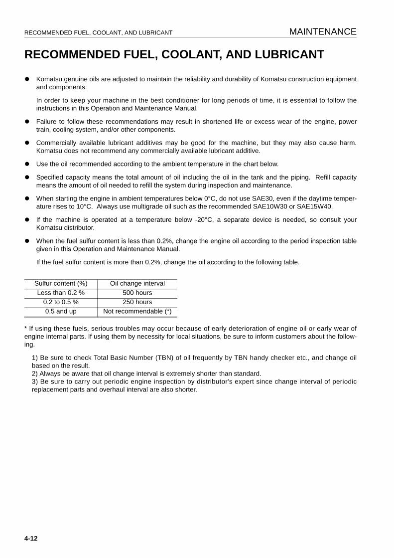
RECOMMENDED FUEL, COOLANT, AND LUBRICANT MAINTENANCE
RECOMMENDED FUEL, COOLANT, AND LUBRICANT 4
q Komatsu genuine oils are adjusted to maintain the reliability and durability of Komatsu construction equipmentand components.
In order to keep your machine in the best conditioner for long periods of time, it is essential to follow theinstructions in this Operation and Maintenance Manual.
q Failure to follow these recommendations may result in shortened life or excess wear of the engine, powertrain, cooling system, and/or other components.
q Commercially available lubricant additives may be good for the machine, but they may also cause harm.Komatsu does not recommend any commercially available lubricant additive.
q Use the oil recommended according to the ambient temperature in the chart below.
q Specified capacity means the total amount of oil including the oil in the tank and the piping. Refill capacitymeans the amount of oil needed to refill the system during inspection and maintenance.
q When starting the engine in ambient temperatures below 0°C, do not use SAE30, even if the daytime temper-ature rises to 10°C. Always use multigrade oil such as the recommended SAE10W30 or SAE15W40.
q If the machine is operated at a temperature below -20°C, a separate device is needed, so consult yourKomatsu distributor.
q When the fuel sulfur content is less than 0.2%, change the engine oil according to the period inspection tablegiven in this Operation and Maintenance Manual.
If the fuel sulfur content is more than 0.2%, change the oil according to the following table.
* If using these fuels, serious troubles may occur because of early deterioration of engine oil or early wear ofengine internal parts. If using them by necessity for local situations, be sure to inform customers about the follow-ing.
1) Be sure to check Total Basic Number (TBN) of oil frequently by TBN handy checker etc., and change oilbased on the result.2) Always be aware that oil change interval is extremely shorter than standard.3) Be sure to carry out periodic engine inspection by distributor's expert since change interval of periodicreplacement parts and overhaul interval are also shorter.
Sulfur content (%) Oil change intervalLess than 0.2 % 500 hours
0.2 to 0.5 % 250 hours0.5 and up Not recommendable (*)
4-12
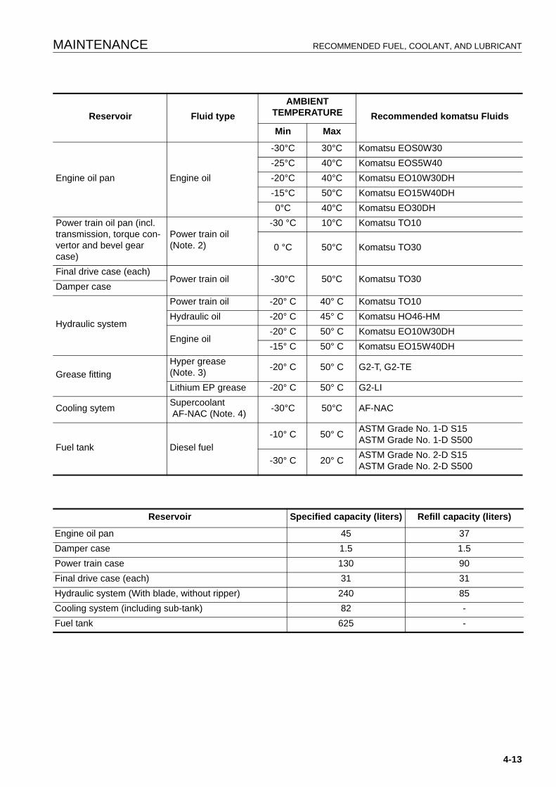
MAINTENANCE RECOMMENDED FUEL, COOLANT, AND LUBRICANT
Reservoir Fluid typeAMBIENT
TEMPERATURE Recommended komatsu FluidsMin Max
Engine oil pan Engine oil
-30°C 30°C Komatsu EOS0W30-25°C 40°C Komatsu EOS5W40-20°C 40°C Komatsu EO10W30DH-15°C 50°C Komatsu EO15W40DH0°C 40°C Komatsu EO30DH
Power train oil pan (incl. transmission, torque con-vertor and bevel gear case)
Power train oil (Note. 2)
-30 °C 10°C Komatsu TO10
0 °C 50°C Komatsu TO30
Final drive case (each)Power train oil -30°C 50°C Komatsu TO30
Damper case
Hydraulic system
Power train oil -20° C 40° C Komatsu TO10Hydraulic oil -20° C 45° C Komatsu HO46-HM
Engine oil-20° C 50° C Komatsu EO10W30DH-15° C 50° C Komatsu EO15W40DH
Grease fittingHyper grease(Note. 3) -20° C 50° C G2-T, G2-TE
Lithium EP grease -20° C 50° C G2-LI
Cooling sytem Supercoolant AF-NAC (Note. 4) -30°C 50°C AF-NAC
Fuel tank Diesel fuel-10° C 50° C ASTM Grade No. 1-D S15
ASTM Grade No. 1-D S500
-30° C 20° C ASTM Grade No. 2-D S15ASTM Grade No. 2-D S500
Reservoir Specified capacity (liters) Refill capacity (liters)
Engine oil pan 45 37Damper case 1.5 1.5Power train case 130 90Final drive case (each) 31 31Hydraulic system (With blade, without ripper) 240 85Cooling system (including sub-tank) 82 -Fuel tank 625 -
4-13
RECOMMENDED FUEL, COOLANT, AND LUBRICANT MAINTENANCE
NOTICEAlways use diesel oil for the fuel.To ensure good fuel consumption characteristics and exhaust gas characteristics, the engine mounted onthis machine uses an electronically controlled high-pressure fuel injection device. This device requireshigh precision parts and lubrication, so if low viscosity fuel with low lubricating ability is used, the durabil-ity may drop markedly.
Note 1: HTHS ( High-Temperature High-Shear Viscosity 150°C), specified by ASTM D4741 must be equal to orhigher than 3.5 mPa-S. Komatsu EOS0W30 and EOS5W40 are the most suitable oils.
Note 2: Powertrain oil has different properties from engine oil. Be sure to use the recommended oils.
Note 3: Hyper grease (G2-T, G2-TE) has a high performance.
When it is necessary to improve the lubricating ability of the grease in order to prevent squeaking of pins andbushings, the use of G2-T or G2-TE is recommended.
Note. 4: Supercoolant (AF-NAC)
1) Coolant has the important function of anticorrosion as well as antifreeze.
Even in the areas where freezing is not an issue, the use of antifreeze coolant is essential.
Komatsu machines are supplied with Komatsu Supercoolant AF-NAC. Komatsu Supercoolant AF-NAC has excel-lent anticorrosion, antifreeze and cooling properties and can be used continuously for 2 years or 4000 hours.
Komatsu Supercoolant AF-NAC is strongly recommended wherever available.
2) For details of the ratio when diluting super coolant with water, see “CLEAN INSIDE OF COOLING SYSTEM (4-20)“.
Supercoolant AF-NAC may be supplied in premix . In this case, always top off with premix solution. ( never dilutewith water)
3) To maintain the anticorrosion properties of Supercoolant AF-NAC, always keep the density of Supercoolantbetween 30% and 68%.
RECOMMENDED BRANDS, RECOMMENDED QUALITY FOR PRODUCTS OTHER THAN KOMATSU GENUINE OIL 4
When using commercially available oils other than Komatsu genuine oil, or when checking the latest specifica-tions, refer to the Komatsu web page or consult your Komatsu distributor.
4-14
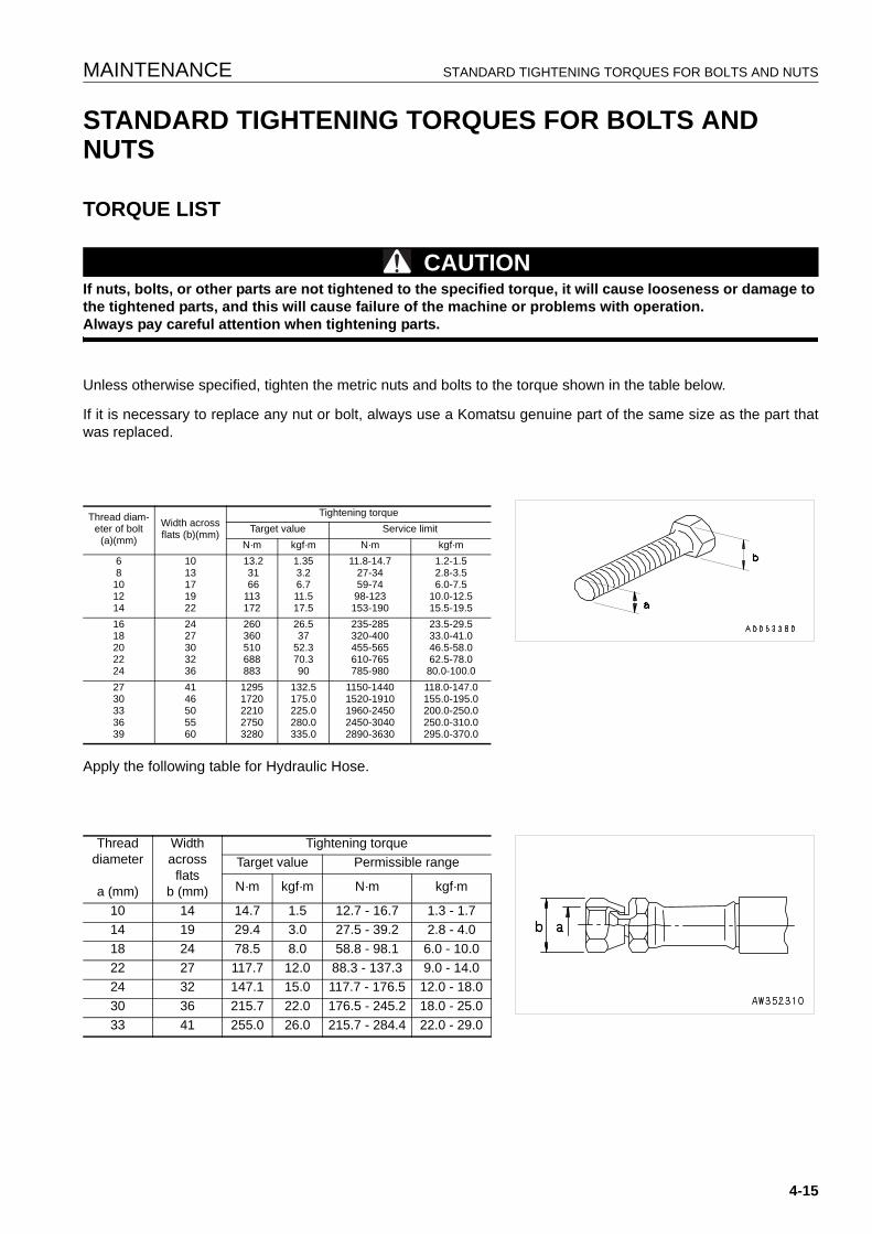
MAINTENANCE STANDARD TIGHTENING TORQUES FOR BOLTS AND NUTS
STANDARD TIGHTENING TORQUES FOR BOLTS AND NUTS 4
TORQUE LIST 4
CAUTIONIf nuts, bolts, or other parts are not tightened to the specified torque, it will cause looseness or damage to the tightened parts, and this will cause failure of the machine or problems with operation.Always pay careful attention when tightening parts.
Unless otherwise specified, tighten the metric nuts and bolts to the torque shown in the table below.
If it is necessary to replace any nut or bolt, always use a Komatsu genuine part of the same size as the part thatwas replaced.
Apply the following table for Hydraulic Hose.
Thread diam-eter of bolt
(a)(mm)
Width across flats (b)(mm)
Tightening torqueTarget value Service limit
N·m kgf·m N·m kgf·m68
101214
1013171922
13.2 31 66113172
1.353.26.711.517.5
11.8-14.727-3459-7498-123
153-190
1.2-1.52.8-3.56.0-7.5
10.0-12.515.5-19.5
1618202224
2427303236
260360510688883
26.537
52.370.390
235-285320-400455-565610-765785-980
23.5-29.533.0-41.046.5-58.062.5-78.080.0-100.0
2730333639
4146505560
12951720221027503280
132.5175.0225.0280.0335.0
1150-14401520-19101960-24502450-30402890-3630
118.0-147.0155.0-195.0200.0-250.0250.0-310.0295.0-370.0
Threaddiameter
a (mm)
Widthacross
flatsb (mm)
Tightening torqueTarget value Permissible range
N·m kgf·m N·m kgf·m
10 14 14.7 1.5 12.7 - 16.7 1.3 - 1.714 19 29.4 3.0 27.5 - 39.2 2.8 - 4.018 24 78.5 8.0 58.8 - 98.1 6.0 - 10.022 27 117.7 12.0 88.3 - 137.3 9.0 - 14.024 32 147.1 15.0 117.7 - 176.5 12.0 - 18.030 36 215.7 22.0 176.5 - 245.2 18.0 - 25.033 41 255.0 26.0 215.7 - 284.4 22.0 - 29.0
4-15

PERIODIC REPLACEMENT OF SAFETY CRITICAL PARTS MAINTENANCE
PERIODIC REPLACEMENT OF SAFETY CRITICAL PARTS 4
For using the machine safely for an extended period of time, you are required to periodically replace the safety(critical and fire prevention) related parts listed in the table of important parts on the following page.
Material quality of these parts can change as time passes and they are likely to wear out or deteriorate. However,it is difficult to determine the extent of wear or deterioration at the time of periodic maintenance. Hence, it isrequired to replace them with new ones regardless of their condition after a certain period of usage. This is impor-tant to ensure that these parts maintain their full performance at all times.
Furthermore, should anything abnormal be found on any of these parts, replace it with a new one even if the peri-odic replacement time for the part has not yet arrived.
If any of the hose clamps show deterioration like deformation or cracking, replace the clamps at the same time asthe hoses.
Also perform the following checks with hydraulic hoses which need to be replaced periodically. Tighten all looseclamps and replace defective hoses, as required.
When replacing hoses, always replace O-rings, gaskets, and other such parts at the same time.
Have your Komatsu distributor replace the critical parts.
SAFETY CRITICAL PARTS 4
Replace wear parts such as the filter element or air cleaner element at the time of periodic maintenance or beforethey reach the wear limit. The wear parts should be replaced correctly in order to ensure more economic use ofthe machine. When replacing parts, always use Komatsu genuine parts.
As a result of our continuous efforts to improve product quality, the part number may change, so inform yourKomatsu distributor of the machine serial number and check for the latest part number when ordering parts.
NO. Safety critical parts for periodic replacement Q'ty Replacement interval1 Fuel hose (fuel strainer - engine entrance) 1
Every 2 years or 4000 hours, whichever comes sooner
2 Fuel hose (engine return spout- fuel tank) 13 Fuel hose (engine supil spout - fuel tank) 14 Fuel hose (fuel tank - fuel strainer) 25 Fuel hose (fuel tank - water drain valve) 16 Hose between torque converter oil cooler and power train assembly 17 Hose between power train pump and power train filter 18 Hose between power train filter and power train assembly 19 Hose between transmission case and steering case 1
10 Power train pressure detection hose assembly 111 Hose between end face of right pivot shaft and straight frame relay tube 212 Hose between straight frame relay tube and blade tilt cylinder 213 Hose between HSS motor and main control valve 214 Hose between HSS pump and drain relay block 1
4-16

MAINTENANCE PERIODIC REPLACEMENT OF SAFETY CRITICAL PARTS
15 Hose between HSS motor and drain relay block 1
Every 2 years or 4000 hours, whichever comes sooner
16 Hose between drain relay block (power train) and hydraulic tank 117 Hose between oil cooler and drain relay block 218 Hose between fan pump and self pressure reducing valve 119 Hose between self pressure reducing valve and fan motor 320 Hose between PPC divider block and main control valve 221 Hose between PPC divider block and fan pump 122 Hose between PPC divider block and work equipment lock valve 223 Hose between the oil cooler bypass valve and hydraulic oil cooler 224 Hose between self pressure reducing valve and drain relay block 125 Hose between main control valve and drain relay block 126 Hose between fan motor and hydraulic tank 4
27 Hose between self pressure reducing valve and work equipment lock valve block 1
28 Hose between work equipment lock valve block and main control valve 229 Hose between main control valve and hydraulic tank 130 Hose between HSS pump and main control valve 2
31 Hose between main control valve and ripper relay block (fixed multi-shank rip-per) 2
32 Hose between main control valve and ripper relay block (variable multi-shank ripper) 4
33 Hose between oil cooler bypass valve and hydraulic tank 134 Hose between ripper relay block and ripper cylinder (fixed multi-shank ripper) 2
35 Hose between ripper relay block and ripper cylinder (variable multi-shank rip-per) 4
36 Hose between main control valve and blade tilt relay cover 437 Hose between main control valve and blade relay tube 238 Hose between drain relay block and hydraulic tank 139 Hose between radiator guard top and lift cylinder 440 Seat belt 1 Every 3 years41 High-pressure piping clamps 1S
Every 8000 hours42 Fuel spray prevention cap 1S
4-17

MAINTENANCE SCHEDULE CHART MAINTENANCE
MAINTENANCE SCHEDULE CHART 4
MAINTENANCE SCHEDULE CHART 4
INITIAL 250 HOURS SERVICE (ONLY AFTER THE FIRST 250 HOURS) 4
REPLACE POWER TRAIN OIL FILTER ELEMENT......................................................................................... 4-504CHANGE OIL IN POWER TRAIN CASE, WASH STRAINERS (POWER TRAIN PUMP STRAINER, SCAVENGING PUMP STRAINER) .................................................................................................................. 4-554CHANGE OIL IN FINAL DRIVE CASE ............................................................................................................. 4-574CHANGE OIL IN HYDRAULIC TANK, REPLACE HYDRAURIC OIL FILTER ELEMENT................................ 4-654
WHEN REQUIRED 4
CLEAN INSIDE OF COOLING SYSTEM.......................................................................................................... 4-204CHECK, CLEAN AND REPLACE AIR CLEANER ELEMENT .......................................................................... 4-224CHECK ELECTRICAL INTAKE AIR HEATER.................................................................................................. 4-244CHECK AND ADJUST TRACK TENSION........................................................................................................ 4-244CHECK AND TIGHTEN TRACK SHOE BOLTS ............................................................................................... 4-264REVERSE AND REPLACE THE END BITS AND CUTTING EDGES.............................................................. 4-274CLEAN, CHECK RADIATOR FINS AND OIL COOLER FINS .......................................................................... 4-294REPLACE AIR CONDITIONER BELT .............................................................................................................. 4-314CLEAN AND CHECK HYDRAULIC COOLER FINS......................................................................................... 4-324CLEAN, CHECK AIR CONDITIONER CONDENSER FINS ............................................................................ 4-324ADJUST IDLER CLEARANCE.......................................................................................................................... 4-334CHECK UNDERCARRIAGE OIL ...................................................................................................................... 4-334CLEAN AIR CONDITIONER AIR FILTER (FRESH/RECIRC FILTER) ............................................................. 4-344CHECK AND ADJUST AIR CONDITIONER..................................................................................................... 4-354CHECK WINDOW WASHER FLUID LEVEL, ADD FLUID ............................................................................... 4-364REPLACE WIPER BLADE................................................................................................................................ 4-364PROCEDURE FOR RELEASING INTERNAL PRESSURE OF HYDRAULIC CIRCUIT .................................. 4-374LUBRICATING .................................................................................................................................................. 4-384
CHECK BEFORE STARTING 4
EVERY 250 HOURS SERVICE 4
LUBRICATING .................................................................................................................................................. 4-404CHECK OIL LEVEL IN FINAL DRIVE CASE, ADD OIL.................................................................................... 4-434CHECK LEVEL OF BATTERY ELECTROLYTE............................................................................................... 4-434CHECK ALTERNATOR DRIVE BELT TENSION, ADJUST ............................................................................. 4-454CHECK BRAKE PERFORMANCE ................................................................................................................... 4-464
EVERY 500 HOURS SERVICE 4
REPLACE FUEL PRE-FILTER CARTRIDGE ................................................................................................... 4-484CHECK FOR LOOSE ROPSCAB MOUNT BOLTS .......................................................................................... 4-494REPLACE POWER TRAIN OIL FILTER ELEMENT......................................................................................... 4-504REPLACE HYDRAULIC TANK BREATHER ELEMENT .................................................................................. 4-514CHANGE OIL IN ENGINE OIL PAN, REPLACE ENGINE OIL FILTER CARTRIDGE...................................... 4-524
4-18

MAINTENANCE MAINTENANCE SCHEDULE CHART
EVERY 1000 HOURS SERVICE 4
CHANGE OIL IN POWER TRAIN CASE, WASH STRAINERS (POWER TRAIN PUMP STRAINER, SCAVENGING PUMP STRAINER) .................................................................................................................. 4-554CHANGE OIL IN FINAL DRIVE CASE ............................................................................................................. 4-574WASH POWER TRAIN CASE BREATHER...................................................................................................... 4-584LUBRICATE UNIVERSAL JOINT ..................................................................................................................... 4-584CHECK ALL TIGHTENING POINTS OF ENGIN EXHAUST PIPE CLAMPS ................................................... 4-594CHECK, CLEAN FUEL STRAINER .................................................................................................................. 4-594REPLACE CORROSION RESISTOR CARTRIDGE......................................................................................... 4-604REPLACE FUEL MAIN FILTER CARTRIDGE.................................................................................................. 4-604LUBRICATE DOOR HINGE.............................................................................................................................. 4-634CHECK DOOR LATCH..................................................................................................................................... 4-634CHECK DOOR LOCK STRIKER ...................................................................................................................... 4-634REPLACE DOOR DAMPER ............................................................................................................................. 4-644
EVERY 2000 HOURS SERVICE 4
CHANGE OIL IN HYDRAULIC TANK, REPLACE HYDRAURIC OIL FILTER ELEMENT................................ 4-654CLEAN ENGINE BREATHER ELEMENT......................................................................................................... 4-664CHECK ALTERNATOR .................................................................................................................................... 4-664CHANGE OIL IN DAMPER CASE, CLEAN DAMPER BREATHER ................................................................. 4-664CHECK PIVOT BEARING OIL LEVEL, ADD OIL ............................................................................................. 4-684CHECKING CHARGE PRESSURE OF NITROGEN GAS IN ACCUMULATOR (FOR CONTROL CIRCUIT). 4-684
EVERY 4000 HOURS SERVICE 4
REPLACE ACCUMULATOR (FOR CONTROL CIRCUIT ) .............................................................................. 4-724CHECK PLAY OF TURBOCHARGER ROTOR................................................................................................ 4-724CHECK ENGINE VALVE CLEARANCE, ADJUST ........................................................................................... 4-724CHECK WATER PUMP .................................................................................................................................... 4-734CHECK STARTING MOTOR............................................................................................................................ 4-734CHECK VIBRATION DAMPER......................................................................................................................... 4-734CHECKING FOR LOOSENESS OF HIGH-PRESSURE CLAMP, HARDENING OF RUBBER ....................... 4-744CHECKING FOR MISSING FUEL SPRAY PREVENTION CAP, HARDENING OF RUBBER......................... 4-754
EVERY 8000 HOURS SERVICE 4
REPLACE HIGH-PRESSURE PIPING CLAMP................................................................................................ 4-764REPLACE FUEL SPLAY PREVENTION CAP.................................................................................................. 4-764
4-19
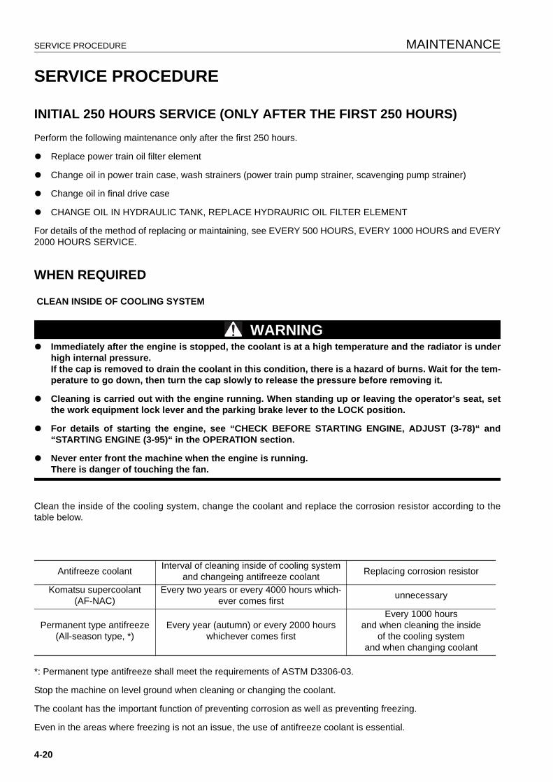
SERVICE PROCEDURE MAINTENANCE
SERVICE PROCEDURE 4
INITIAL 250 HOURS SERVICE (ONLY AFTER THE FIRST 250 HOURS) 4
Perform the following maintenance only after the first 250 hours.
q Replace power train oil filter element
q Change oil in power train case, wash strainers (power train pump strainer, scavenging pump strainer)
q Change oil in final drive case
q CHANGE OIL IN HYDRAULIC TANK, REPLACE HYDRAURIC OIL FILTER ELEMENT
For details of the method of replacing or maintaining, see EVERY 500 HOURS, EVERY 1000 HOURS and EVERY2000 HOURS SERVICE.
WHEN REQUIRED 4
CLEAN INSIDE OF COOLING SYSTEM
WARNINGq Immediately after the engine is stopped, the coolant is at a high temperature and the radiator is under
high internal pressure.If the cap is removed to drain the coolant in this condition, there is a hazard of burns. Wait for the tem-perature to go down, then turn the cap slowly to release the pressure before removing it.
q Cleaning is carried out with the engine running. When standing up or leaving the operator's seat, setthe work equipment lock lever and the parking brake lever to the LOCK position.
q For details of starting the engine, see “CHECK BEFORE STARTING ENGINE, ADJUST (3-78)“ and“STARTING ENGINE (3-95)“ in the OPERATION section.
q Never enter front the machine when the engine is running.There is danger of touching the fan.
Clean the inside of the cooling system, change the coolant and replace the corrosion resistor according to thetable below.
*: Permanent type antifreeze shall meet the requirements of ASTM D3306-03.
Stop the machine on level ground when cleaning or changing the coolant.
The coolant has the important function of preventing corrosion as well as preventing freezing.
Even in the areas where freezing is not an issue, the use of antifreeze coolant is essential.
Antifreeze coolant Interval of cleaning inside of cooling system and changeing antifreeze coolant Replacing corrosion resistor
Komatsu supercoolant(AF-NAC)
Every two years or every 4000 hours which-ever comes first unnecessary
Permanent type antifreeze(All-season type, *)
Every year (autumn) or every 2000 hours whichever comes first
Every 1000 hoursand when cleaning the inside
of the cooling systemand when changing coolant
4-20
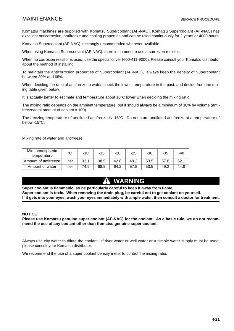
MAINTENANCE SERVICE PROCEDURE
Komatsu machines are supplied with Komatsu Supercoolant (AF-NAC). Komatsu Supercoolant (AF-NAC) hasexcellent anticorrosion, antifreeze and cooling properties and can be used continuously for 2 years or 4000 hours.
Komatsu Supercoolant (AF-NAC) is strongly recommended wherever available.
When using Komatsu Supercoolant (AF-NAC), there is no need to use a corrosion resistor.
When no corrosion resistor is used, use the special cover (600-411-9000). Please consult your Komatsu distributorabout the method of installing.
To maintain the anticorrosion properties of Supercoolant (AF-NAC), always keep the density of Supercoolantbetween 30% and 68%.
When deciding the ratio of antifreeze to water, check the lowest temperature in the past, and decide from the mix-ing table given below.
It is actually better to estimate and temperature about 10°C lower when deciding the mixing ratio.
The mixing ratio depends on the ambient temperature, but it should always be a minimum of 30% by volume (anti-freeze/total amount of coolant x 100).
The freezing temperature of undiluted antifreeze is -15°C. Do not store undiluted antifreeze at a temperature ofbelow -15°C.
Mixing rate of water and antifreeze
WARNINGSuper coolant is flammable, so be particularly careful to keep it away from flame.Super coolant is toxic. When removing the drain plug, be careful not to get coolant on yourself.If it gets into your eyes, wash your eyes immediately with ample water, then consult a doctor for treatment.
NOTICEPlease use Komatsu genuine super coolant (AF-NAC) for the coolant. As a basic rule, we do not recom-mend the use of any coolant other than Komatsu genuine super coolant.
Always use city water to dilute the coolant. If river water or well water or a simple water supply must be used,please consult your Komatsu distributor.
We recommend the use of a super coolant density meter to control the mixing ratio.
Min. atmospheric temperature °C -10 -15 -20 -25 -30 -35 -40
Amount of antifreeze liter 32.1 38.5 42.8 49.2 53.5 57.8 62.1Amount of water liter 74.9 68.5 64.2 57.8 53.5 49.2 44.9
4-21
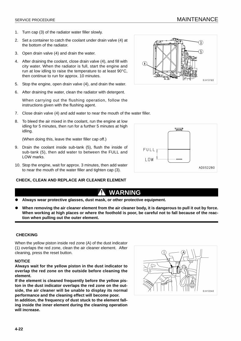
SERVICE PROCEDURE MAINTENANCE
1. Turn cap (3) of the radiator water filler slowly.
2. Set a container to catch the coolant under drain valve (4) atthe bottom of the radiator.
3. Open drain valve (4) and drain the water.
4. After draining the coolant, close drain valve (4), and fill withcity water. When the radiator is full, start the engine andrun at low idling to raise the temperature to at least 90°C,then continue to run for approx. 10 minutes.
5. Stop the engine, open drain valve (4), and drain the water.
6. After draining the water, clean the radiator with detergent.
When carrying out the flushing operation, follow theinstructions given with the flushing agent.
7. Close drain valve (4) and add water to near the mouth of the water filler.
8. To bleed the air mixed in the coolant, run the engine at lowidling for 5 minutes, then run for a further 5 minutes at highidling.
(When doing this, leave the water filler cap off.)
9. Drain the coolant inside sub-tank (5), flush the inside ofsub-tank (5), then add water to between the FULL andLOW marks.
10. Stop the engine, wait for approx. 3 minutes, then add waterto near the mouth of the water filler and tighten cap (3).
CHECK, CLEAN AND REPLACE AIR CLEANER ELEMENT
WARNINGq Always wear protective glasses, dust mask, or other protective equipment.
q When removing the air cleaner element from the air cleaner body, it is dangerous to pull it out by force.When working at high places or where the foothold is poor, be careful not to fall because of the reac-tion when pulling out the outer element.
CHECKING
When the yellow piston inside red zone (A) of the dust indicator(1) overlaps the red zone, clean the air cleaner element. Aftercleaning, press the reset button.
NOTICEAlways wait for the yellow piston in the dust indicator tooverlap the red zone on the outside before cleaning theelement.If the element is cleaned frequently before the yellow pis-ton in the dust indicator overlaps the red zone on the out-side, the air cleaner will be unable to display its normalperformance and the cleaning effect will become poor.In addition, the frequency of dust stuck to the element fall-ing inside the inner element during the cleaning operationwill increase.
4-22
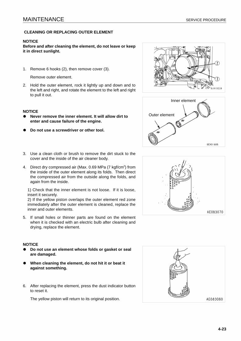
MAINTENANCE SERVICE PROCEDURE
CLEANING OR REPLACING OUTER ELEMENT
NOTICEBefore and after cleaning the element, do not leave or keepit in direct sunlight.
1. Remove 6 hooks (2), then remove cover (3).
Remove outer element.
2. Hold the outer element, rock it lightly up and down and tothe left and right, and rotate the element to the left and rightto pull it out.
NOTICEq Never remove the inner element. It will allow dirt to
enter and cause failure of the engine.
q Do not use a screwdriver or other tool.
3. Use a clean cloth or brush to remove the dirt stuck to thecover and the inside of the air cleaner body.
4. Direct dry compressed air (Max. 0.69 MPa (7 kgf/cm2) fromthe inside of the outer element along its folds. Then directthe compressed air from the outside along the folds, andagain from the inside.
1) Check that the inner element is not loose. If it is loose,insert it securely.2) If the yellow piston overlaps the outer element red zoneimmediately after the outer element is cleaned, replace theinner and outer elements.
5. If small holes or thinner parts are found on the elementwhen it is checked with an electric bulb after cleaning anddrying, replace the element.
NOTICEq Do not use an element whose folds or gasket or seal
are damaged.
q When cleaning the element, do not hit it or beat it against something.
6. After replacing the element, press the dust indicator buttonto reset it.
The yellow piston will return to its original position.
Outer element
Inner element
4-23
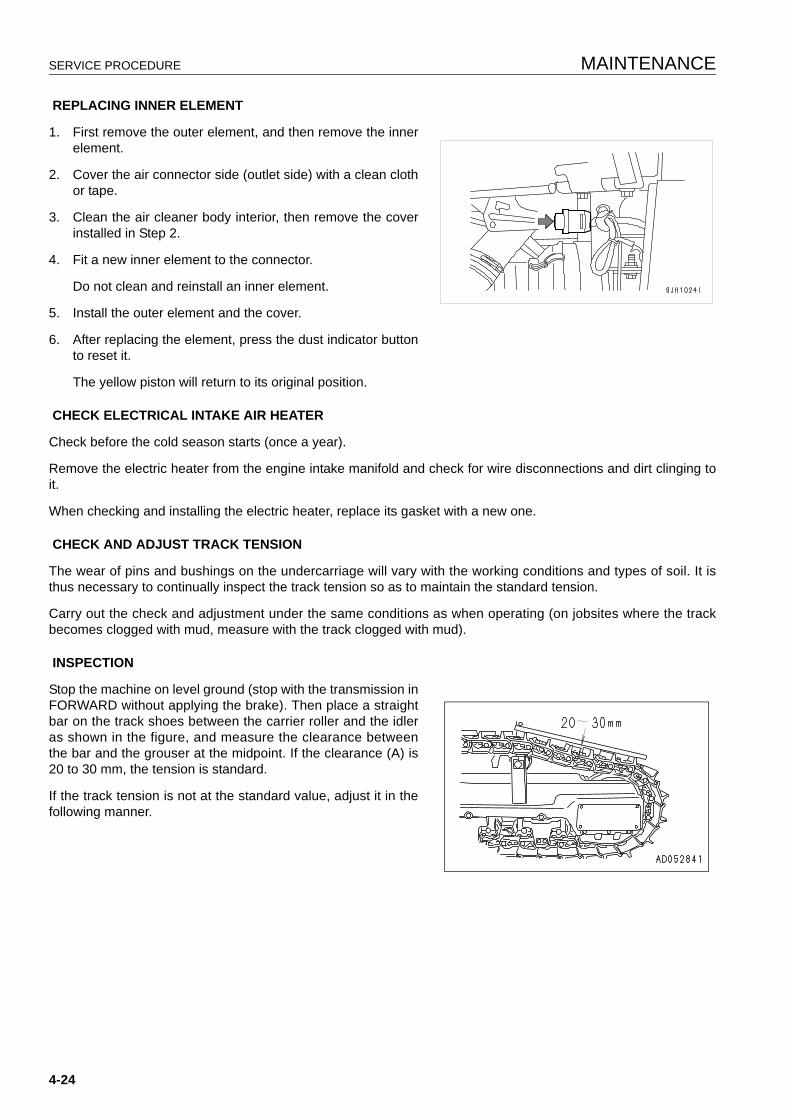
SERVICE PROCEDURE MAINTENANCE
REPLACING INNER ELEMENT
1. First remove the outer element, and then remove the innerelement.
2. Cover the air connector side (outlet side) with a clean clothor tape.
3. Clean the air cleaner body interior, then remove the coverinstalled in Step 2.
4. Fit a new inner element to the connector.
Do not clean and reinstall an inner element.
5. Install the outer element and the cover.
6. After replacing the element, press the dust indicator buttonto reset it.
The yellow piston will return to its original position.
CHECK ELECTRICAL INTAKE AIR HEATER
Check before the cold season starts (once a year).
Remove the electric heater from the engine intake manifold and check for wire disconnections and dirt clinging toit.
When checking and installing the electric heater, replace its gasket with a new one.
CHECK AND ADJUST TRACK TENSION
The wear of pins and bushings on the undercarriage will vary with the working conditions and types of soil. It isthus necessary to continually inspect the track tension so as to maintain the standard tension.
Carry out the check and adjustment under the same conditions as when operating (on jobsites where the trackbecomes clogged with mud, measure with the track clogged with mud).
INSPECTION
Stop the machine on level ground (stop with the transmission inFORWARD without applying the brake). Then place a straightbar on the track shoes between the carrier roller and the idleras shown in the figure, and measure the clearance betweenthe bar and the grouser at the midpoint. If the clearance (A) is20 to 30 mm, the tension is standard.
If the track tension is not at the standard value, adjust it in thefollowing manner.
4-24
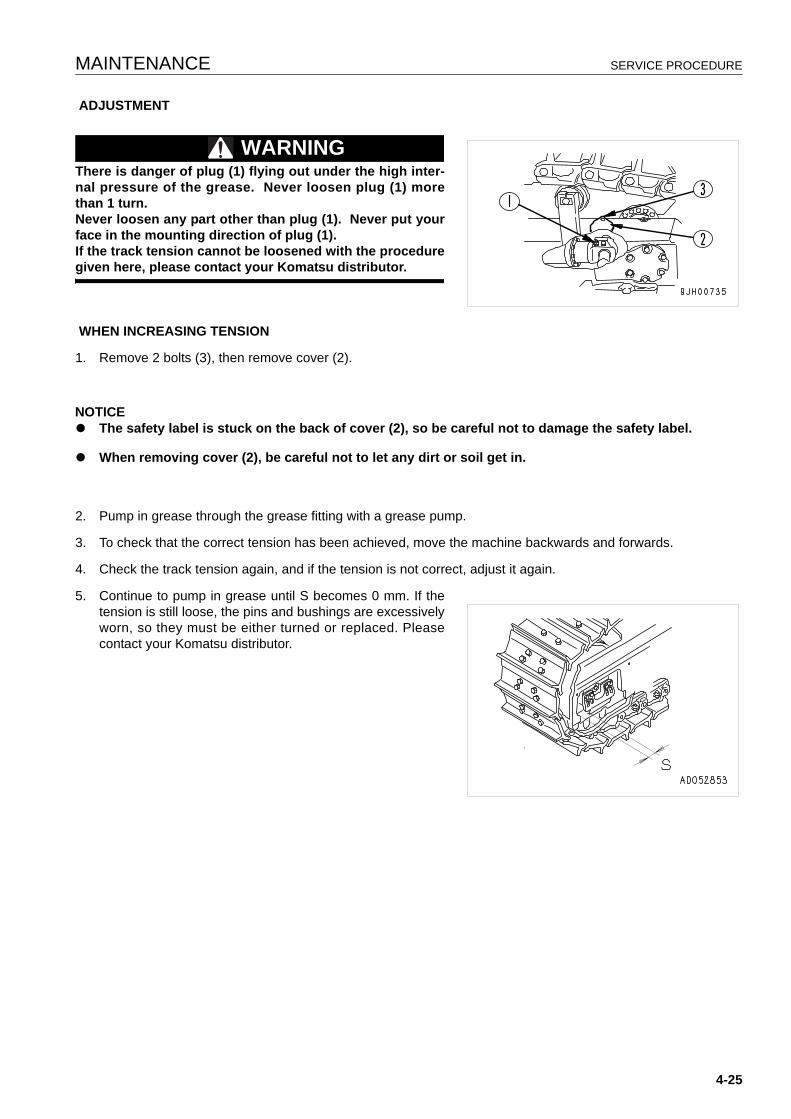
MAINTENANCE SERVICE PROCEDURE
ADJUSTMENT
WARNINGThere is danger of plug (1) flying out under the high inter-nal pressure of the grease. Never loosen plug (1) morethan 1 turn.Never loosen any part other than plug (1). Never put yourface in the mounting direction of plug (1).If the track tension cannot be loosened with the proceduregiven here, please contact your Komatsu distributor.
WHEN INCREASING TENSION
1. Remove 2 bolts (3), then remove cover (2).
NOTICEq The safety label is stuck on the back of cover (2), so be careful not to damage the safety label.
q When removing cover (2), be careful not to let any dirt or soil get in.
2. Pump in grease through the grease fitting with a grease pump.
3. To check that the correct tension has been achieved, move the machine backwards and forwards.
4. Check the track tension again, and if the tension is not correct, adjust it again.
5. Continue to pump in grease until S becomes 0 mm. If thetension is still loose, the pins and bushings are excessivelyworn, so they must be either turned or replaced. Pleasecontact your Komatsu distributor.
4-25
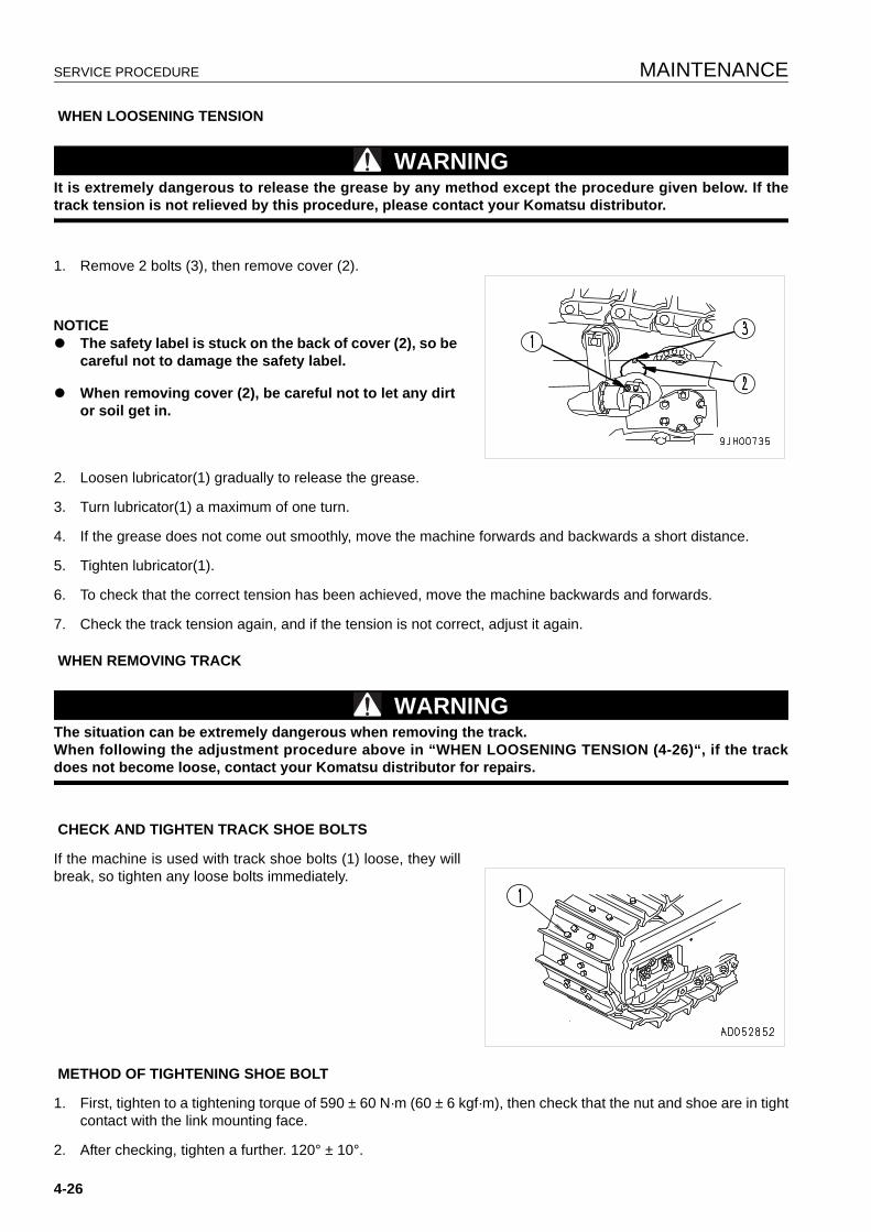
SERVICE PROCEDURE MAINTENANCE
WHEN LOOSENING TENSION
WARNINGIt is extremely dangerous to release the grease by any method except the procedure given below. If thetrack tension is not relieved by this procedure, please contact your Komatsu distributor.
1. Remove 2 bolts (3), then remove cover (2).
NOTICEq The safety label is stuck on the back of cover (2), so be
careful not to damage the safety label.
q When removing cover (2), be careful not to let any dirt or soil get in.
2. Loosen lubricator(1) gradually to release the grease.
3. Turn lubricator(1) a maximum of one turn.
4. If the grease does not come out smoothly, move the machine forwards and backwards a short distance.
5. Tighten lubricator(1).
6. To check that the correct tension has been achieved, move the machine backwards and forwards.
7. Check the track tension again, and if the tension is not correct, adjust it again.
WHEN REMOVING TRACK
WARNINGThe situation can be extremely dangerous when removing the track.When following the adjustment procedure above in “WHEN LOOSENING TENSION (4-26)“, if the trackdoes not become loose, contact your Komatsu distributor for repairs.
CHECK AND TIGHTEN TRACK SHOE BOLTS
If the machine is used with track shoe bolts (1) loose, they willbreak, so tighten any loose bolts immediately.
METHOD OF TIGHTENING SHOE BOLT
1. First, tighten to a tightening torque of 590 ± 60 N·m (60 ± 6 kgf·m), then check that the nut and shoe are in tightcontact with the link mounting face.
2. After checking, tighten a further. 120° ± 10°.
4-26
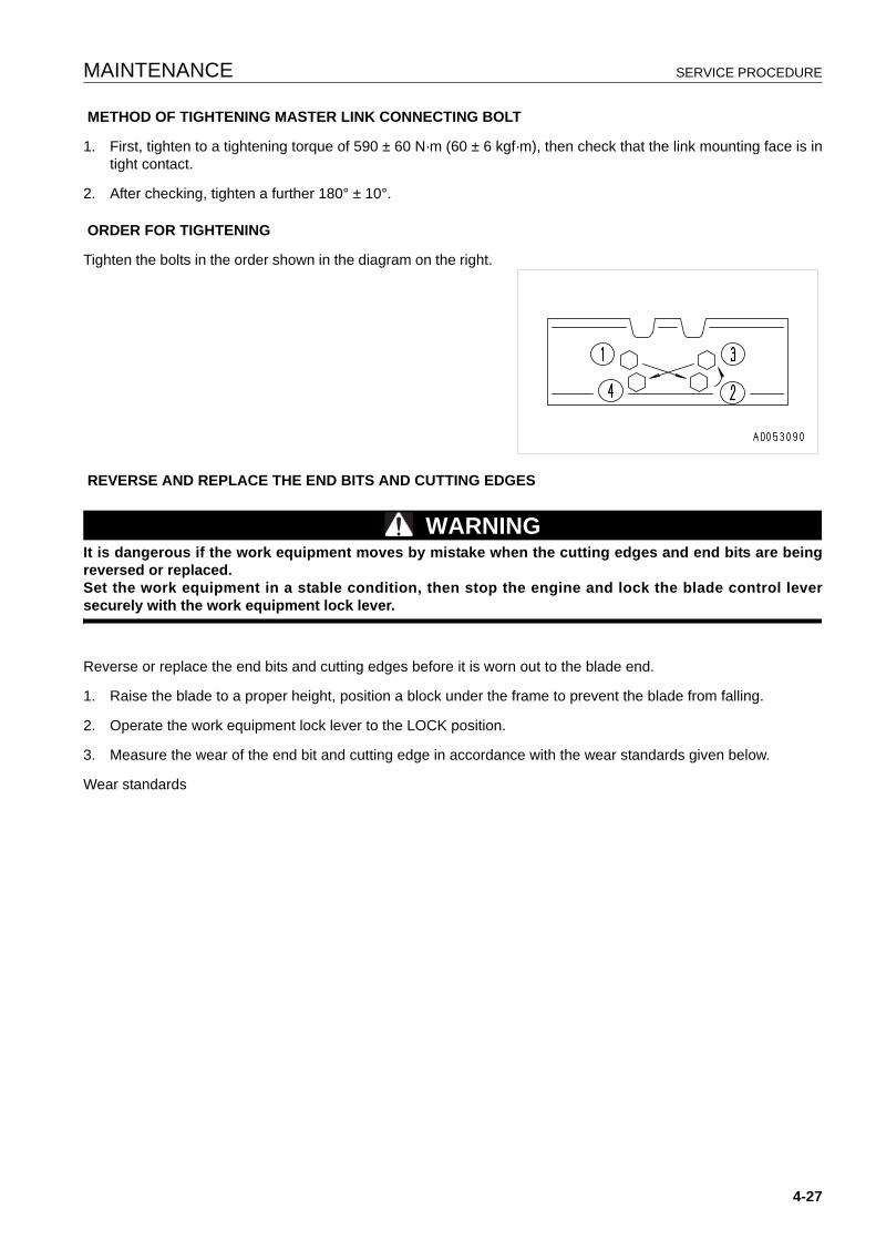
MAINTENANCE SERVICE PROCEDURE
METHOD OF TIGHTENING MASTER LINK CONNECTING BOLT
1. First, tighten to a tightening torque of 590 ± 60 N·m (60 ± 6 kgf·m), then check that the link mounting face is intight contact.
2. After checking, tighten a further 180° ± 10°.
ORDER FOR TIGHTENING
Tighten the bolts in the order shown in the diagram on the right.
REVERSE AND REPLACE THE END BITS AND CUTTING EDGES
WARNINGIt is dangerous if the work equipment moves by mistake when the cutting edges and end bits are beingreversed or replaced.Set the work equipment in a stable condition, then stop the engine and lock the blade control leversecurely with the work equipment lock lever.
Reverse or replace the end bits and cutting edges before it is worn out to the blade end.
1. Raise the blade to a proper height, position a block under the frame to prevent the blade from falling.
2. Operate the work equipment lock lever to the LOCK position.
3. Measure the wear of the end bit and cutting edge in accordance with the wear standards given below.
Wear standards
4-27
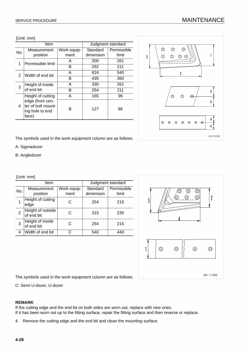
SERVICE PROCEDURE MAINTENANCE
The symbols used in the work equipment column are as follows.
A: Sigmadozer
B: Angledozer
The symbols used in the work equipment column are as follows.
C: Semi U-dozer, U-dozer
REMARKIf the cutting edge and the end bit on both sides are worn out, replace with new ones.If it has been worn out up to the fitting surface, repair the fitting surface and then reverse or replace.
4. Remove the cutting edge and the end bit and clean the mounting surface.
[Unit: mm]Item Judgment standard
No. Measurement position
Work equip-ment
Standard dimension
Permissible limit
1 Permissible limitA 300 261B 292 211
2 Width of end bitA 624 540B 435 360
3 Height of inside of end bit
A 330 261B 254 211
4
Height of cutting edge (from cen-ter of bolt mount-ing hole to end face)
A 165 96
B 127 86
[Unit: mm]Item Judgment standard
No. Measurement position
Work equip-ment
Standard dimension
Permissible limit
1 Height of cutting edge C 254 215
2 Height of outsideof end bit C 315 235
3 Height of inside of end bit C 254 215
4 Width of end bit C 540 440
4-28
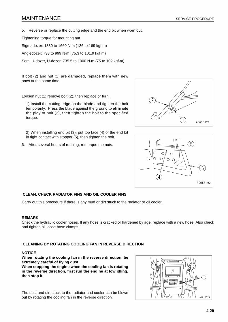
MAINTENANCE SERVICE PROCEDURE
5. Reverse or replace the cutting edge and the end bit when worn out.
Tightening torque for mounting nut
Sigmadozer: 1330 to 1660 N·m (136 to 169 kgf·m)
Angledozer: 738 to 999 N·m (75.3 to 101.9 kgf·m)
Semi U-dozer, U-dozer: 735.5 to 1000 N·m (75 to 102 kgf·m)
If bolt (2) and nut (1) are damaged, replace them with newones at the same time.
Loosen nut (1) remove bolt (2), then replace or turn.
1) Install the cutting edge on the blade and tighten the bolttemporarily. Press the blade against the ground to eliminatethe play of bolt (2), then tighten the bolt to the specifiedtorque.
2) When installing end bit (3), put top face (4) of the end bitin tight contact with stopper (5), then tighten the bolt.
6. After several hours of running, retourque the nuts.
CLEAN, CHECK RADIATOR FINS AND OIL COOLER FINS
Carry out this procedure if there is any mud or dirt stuck to the radiator or oil cooler.
REMARKCheck the hydraulic cooler hoses. If any hose is cracked or hardened by age, replace with a new hose. Also checkand tighten all loose hose clamps.
CLEANING BY ROTATING COOLING FAN IN REVERSE DIRECTION
NOTICEWhen rotating the cooling fan in the reverse direction, beextremely careful of flying dust.When stopping the engine when the cooling fan is rotatingin the reverse direction, first run the engine at low idling,then stop it.
The dust and dirt stuck to the radiator and cooler can be blownout by rotating the cooling fan in the reverse direction.
4-29
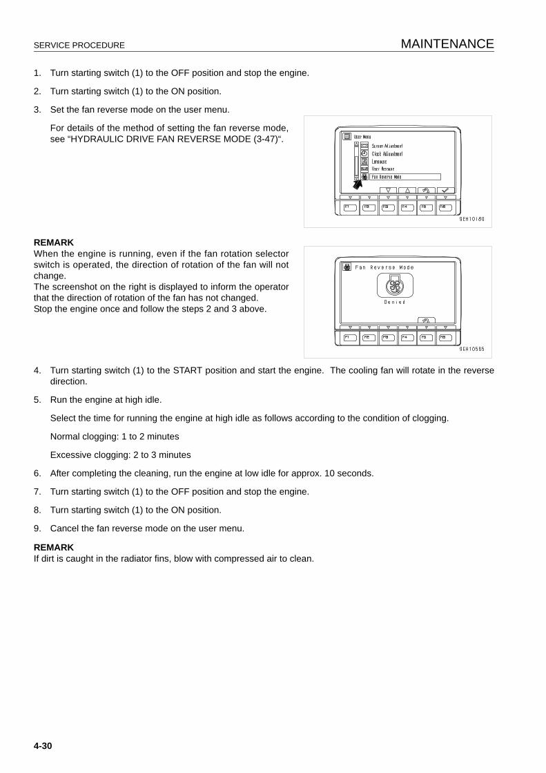
SERVICE PROCEDURE MAINTENANCE
1. Turn starting switch (1) to the OFF position and stop the engine.
2. Turn starting switch (1) to the ON position.
3. Set the fan reverse mode on the user menu.
For details of the method of setting the fan reverse mode,see “HYDRAULIC DRIVE FAN REVERSE MODE (3-47)“.
REMARKWhen the engine is running, even if the fan rotation selectorswitch is operated, the direction of rotation of the fan will notchange.The screenshot on the right is displayed to inform the operatorthat the direction of rotation of the fan has not changed.Stop the engine once and follow the steps 2 and 3 above.
4. Turn starting switch (1) to the START position and start the engine. The cooling fan will rotate in the reversedirection.
5. Run the engine at high idle.
Select the time for running the engine at high idle as follows according to the condition of clogging.
Normal clogging: 1 to 2 minutes
Excessive clogging: 2 to 3 minutes
6. After completing the cleaning, run the engine at low idle for approx. 10 seconds.
7. Turn starting switch (1) to the OFF position and stop the engine.
8. Turn starting switch (1) to the ON position.
9. Cancel the fan reverse mode on the user menu.
REMARKIf dirt is caught in the radiator fins, blow with compressed air to clean.
4-30
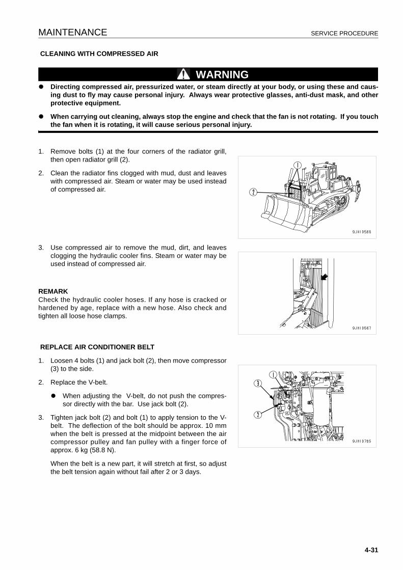
MAINTENANCE SERVICE PROCEDURE
CLEANING WITH COMPRESSED AIR
WARNINGq Directing compressed air, pressurized water, or steam directly at your body, or using these and caus-
ing dust to fly may cause personal injury. Always wear protective glasses, anti-dust mask, and otherprotective equipment.
q When carrying out cleaning, always stop the engine and check that the fan is not rotating. If you touchthe fan when it is rotating, it will cause serious personal injury.
1. Remove bolts (1) at the four corners of the radiator grill,then open radiator grill (2).
2. Clean the radiator fins clogged with mud, dust and leaveswith compressed air. Steam or water may be used insteadof compressed air.
3. Use compressed air to remove the mud, dirt, and leavesclogging the hydraulic cooler fins. Steam or water may beused instead of compressed air.
REMARKCheck the hydraulic cooler hoses. If any hose is cracked orhardened by age, replace with a new hose. Also check andtighten all loose hose clamps.
REPLACE AIR CONDITIONER BELT
1. Loosen 4 bolts (1) and jack bolt (2), then move compressor(3) to the side.
2. Replace the V-belt.
q When adjusting the V-belt, do not push the compres-sor directly with the bar. Use jack bolt (2).
3. Tighten jack bolt (2) and bolt (1) to apply tension to the V-belt. The deflection of the bolt should be approx. 10 mmwhen the belt is pressed at the midpoint between the aircompressor pulley and fan pulley with a finger force ofapprox. 6 kg (58.8 N).
When the belt is a new part, it will stretch at first, so adjustthe belt tension again without fail after 2 or 3 days.
4-31
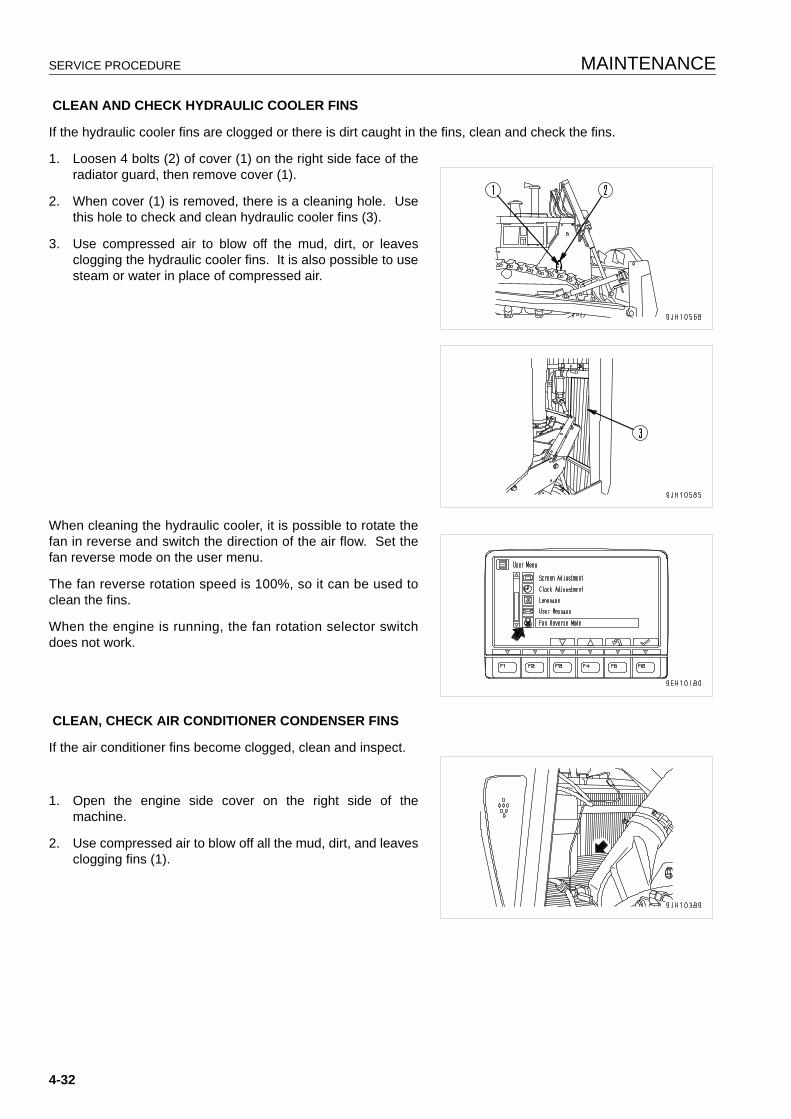
SERVICE PROCEDURE MAINTENANCE
CLEAN AND CHECK HYDRAULIC COOLER FINS
If the hydraulic cooler fins are clogged or there is dirt caught in the fins, clean and check the fins.
1. Loosen 4 bolts (2) of cover (1) on the right side face of theradiator guard, then remove cover (1).
2. When cover (1) is removed, there is a cleaning hole. Usethis hole to check and clean hydraulic cooler fins (3).
3. Use compressed air to blow off the mud, dirt, or leavesclogging the hydraulic cooler fins. It is also possible to usesteam or water in place of compressed air.
When cleaning the hydraulic cooler, it is possible to rotate thefan in reverse and switch the direction of the air flow. Set thefan reverse mode on the user menu.
The fan reverse rotation speed is 100%, so it can be used toclean the fins.
When the engine is running, the fan rotation selector switchdoes not work.
CLEAN, CHECK AIR CONDITIONER CONDENSER FINS
If the air conditioner fins become clogged, clean and inspect.
1. Open the engine side cover on the right side of themachine.
2. Use compressed air to blow off all the mud, dirt, and leavesclogging fins (1).
4-32
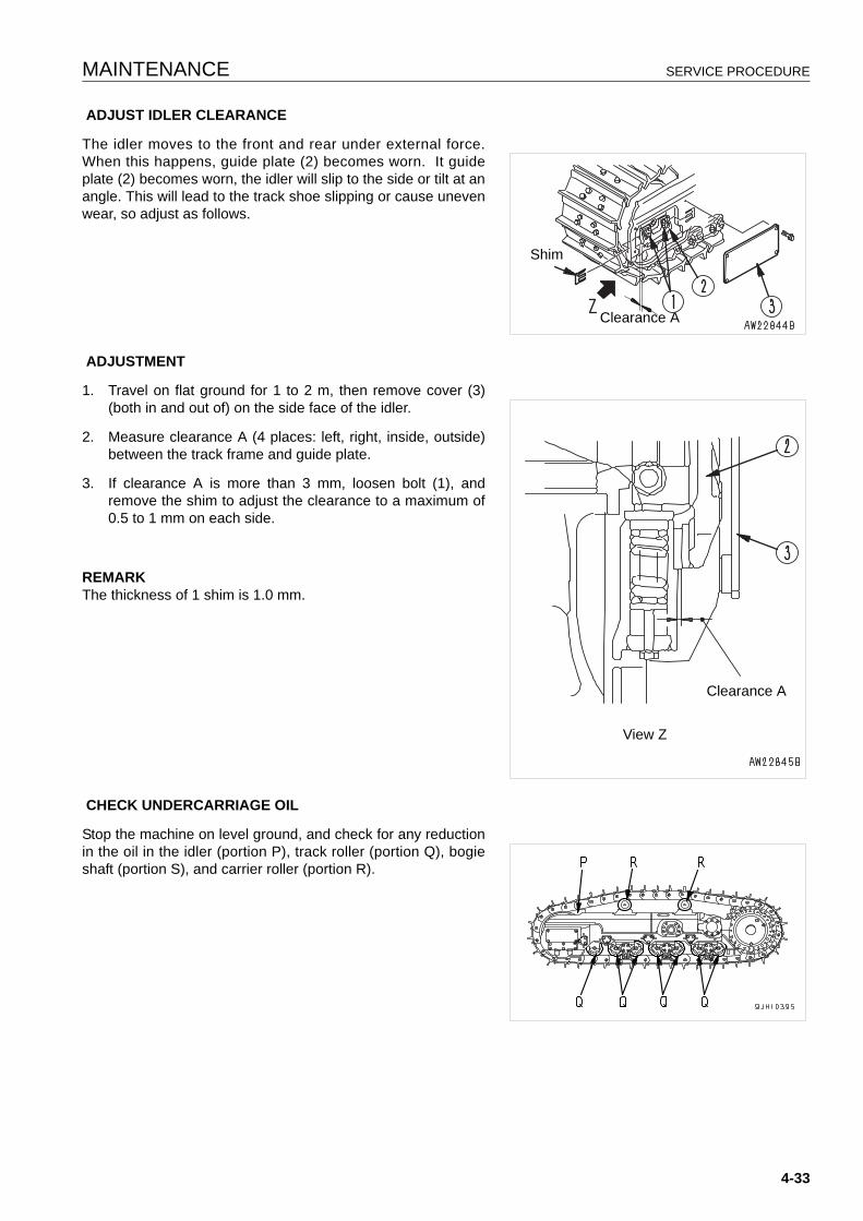
MAINTENANCE SERVICE PROCEDURE
ADJUST IDLER CLEARANCE
The idler moves to the front and rear under external force.When this happens, guide plate (2) becomes worn. It guideplate (2) becomes worn, the idler will slip to the side or tilt at anangle. This will lead to the track shoe slipping or cause unevenwear, so adjust as follows.
ADJUSTMENT
1. Travel on flat ground for 1 to 2 m, then remove cover (3)(both in and out of) on the side face of the idler.
2. Measure clearance A (4 places: left, right, inside, outside)between the track frame and guide plate.
3. If clearance A is more than 3 mm, loosen bolt (1), andremove the shim to adjust the clearance to a maximum of0.5 to 1 mm on each side.
REMARKThe thickness of 1 shim is 1.0 mm.
CHECK UNDERCARRIAGE OIL
Stop the machine on level ground, and check for any reductionin the oil in the idler (portion P), track roller (portion Q), bogieshaft (portion S), and carrier roller (portion R).
Shim
Clearance A
View Z
Clearance A
4-33
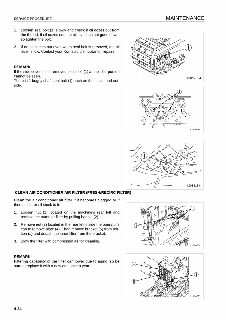
SERVICE PROCEDURE MAINTENANCE
1. Loosen seal bolt (1) slowly and check if oil oozes out fromthe thread. If oil oozes out, the oil level has not gone down,so tighten the bolt.
2. If no oil comes out even when seal bolt is removed, the oillevel is low. Contact your Komatsu distributor for repairs.
REMARKIf the side cover is not removed, seal bolt (1) at the idler portioncannot be seen.There is 1 bogey shaft seal bolt (1) each on the inside and out-side.
CLEAN AIR CONDITIONER AIR FILTER (FRESH/RECIRC FILTER)
Clean the air conditioner air filter if it becomes clogged or ifthere is dirt or oil stuck to it.
1. Loosen nut (1) located on the machine's rear left andremove the outer air filter by pulling handle (2).
2. Remove nut (3) located in the rear left inside the operator'scab to remove plate (4). Then remove bracket (5) from por-tion (a) and detach the inner filter from the bracket.
3. Blow the filter with compressed air for cleaning.
REMARKFiltering capability of the filter can lower due to aging, so besure to replace it with a new one once a year.
4-34
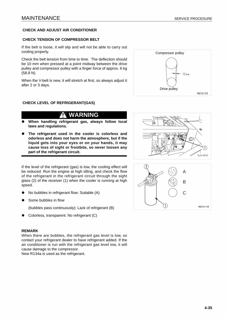
MAINTENANCE SERVICE PROCEDURE
CHECK AND ADJUST AIR CONDITIONER
CHECK TENSION OF COMPRESSOR BELT
If the belt is loose, it will slip and will not be able to carry outcooling properly.
Check the belt tension from time to time. The deflection shouldbe 10 mm when pressed at a point midway between the drivepulley and compressor pulley with a finger force of approx. 6 kg(58.8 N).
When the V-belt is new, it will stretch at first, so always adjust itafter 2 or 3 days.
CHECK LEVEL OF REFRIGERANT(GAS)
WARNINGq When handling refrigerant gas, always follow local
laws and regulations.
q The refrigerant used in the cooler is colorless andodorless and does not harm the atmosphere, but if theliquid gets into your eyes or on your hands, it maycause loss of sight or frostbite, so never loosen anypart of the refrigerant circuit.
If the level of the refrigerant (gas) is low, the cooling effect willbe reduced. Run the engine at high idling, and check the flowof the refrigerant in the refrigerant circuit through the sightglass (2) of the receiver (1) when the cooler is running at highspeed.
q No bubbles in refrigerant flow: Suitable (A)
q Some bubbles in flow
(bubbles pass continuously): Lack of refrigerant (B)
q Colorless, transparent: No refrigerant (C)
REMARKWhen there are bubbles, the refrigerant gas level is low, socontact your refrigerant dealer to have refrigerant added. If theair conditioner is run with the refrigerant gas level low, it willcause damage to the compressor.New R134a is used as the refrigerant.
Compressor pulley
Drive pulley
A
B
C
4-35
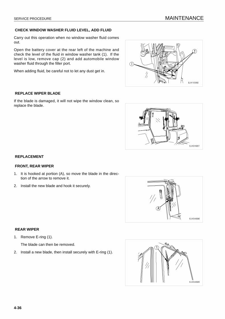
SERVICE PROCEDURE MAINTENANCE
CHECK WINDOW WASHER FLUID LEVEL, ADD FLUID
Carry out this operation when no window washer fluid comesout.
Open the battery cover at the rear left of the machine andcheck the level of the fluid in window washer tank (1). If thelevel is low, remove cap (2) and add automobile windowwasher fluid through the filler port.
When adding fluid, be careful not to let any dust get in.
REPLACE WIPER BLADE
If the blade is damaged, it will not wipe the window clean, soreplace the blade.
REPLACEMENT
FRONT, REAR WIPER
1. It is hooked at portion (A), so move the blade in the direc-tion of the arrow to remove it.
2. Install the new blade and hook it securely.
REAR WIPER
1. Remove E-ring (1).
The blade can then be removed.
2. Install a new blade, then install securely with E-ring (1).
4-36
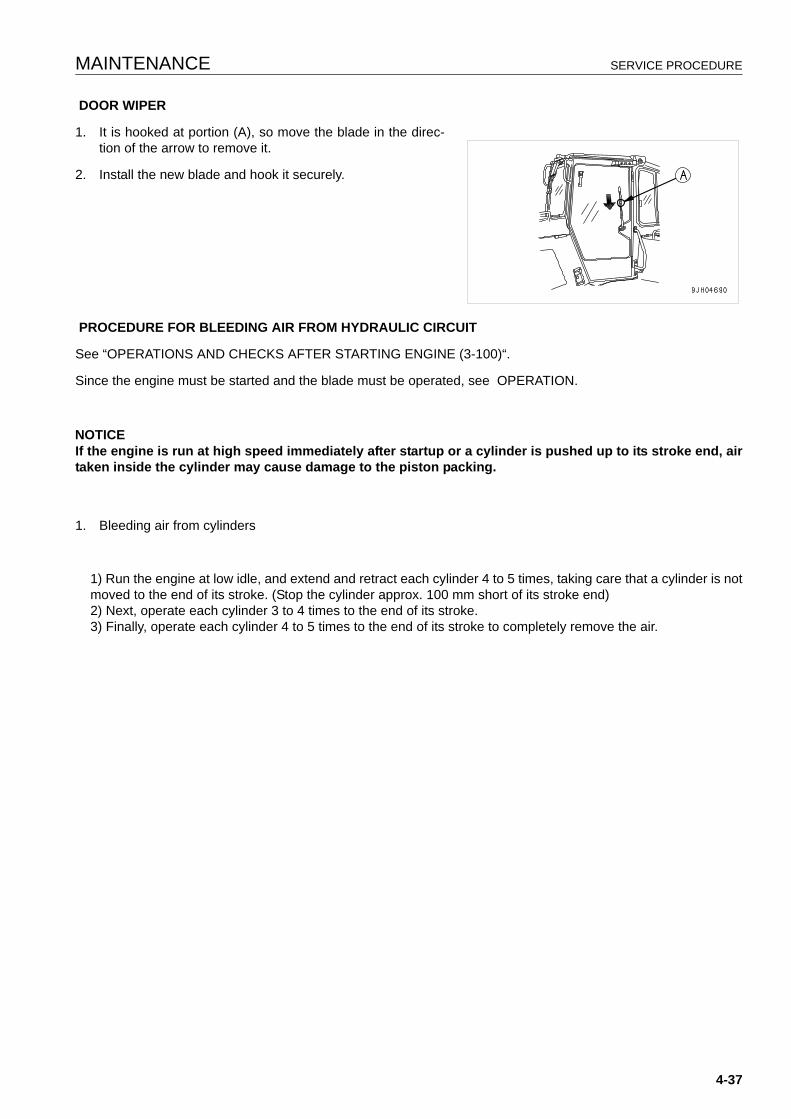
MAINTENANCE SERVICE PROCEDURE
DOOR WIPER
1. It is hooked at portion (A), so move the blade in the direc-tion of the arrow to remove it.
2. Install the new blade and hook it securely.
PROCEDURE FOR BLEEDING AIR FROM HYDRAULIC CIRCUIT
See “OPERATIONS AND CHECKS AFTER STARTING ENGINE (3-100)“.
Since the engine must be started and the blade must be operated, see OPERATION.
NOTICEIf the engine is run at high speed immediately after startup or a cylinder is pushed up to its stroke end, airtaken inside the cylinder may cause damage to the piston packing.
1. Bleeding air from cylinders
1) Run the engine at low idle, and extend and retract each cylinder 4 to 5 times, taking care that a cylinder is notmoved to the end of its stroke. (Stop the cylinder approx. 100 mm short of its stroke end)2) Next, operate each cylinder 3 to 4 times to the end of its stroke.3) Finally, operate each cylinder 4 to 5 times to the end of its stroke to completely remove the air.
4-37
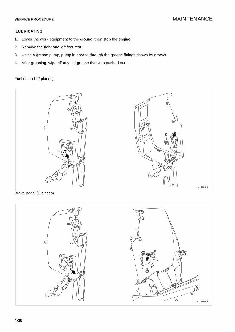
SERVICE PROCEDURE MAINTENANCE
LUBRICATING
1. Lower the work equipment to the ground, then stop the engine.
2. Remove the right and left foot rest.
3. Using a grease pump, pump in grease through the grease fittings shown by arrows.
4. After greasing, wipe off any old grease that was pushed out.
Fuel control (2 places)
Brake pedal (2 places)
4-38
MAINTENANCE SERVICE PROCEDURE
CHECK BEFORE STARTING 4
For details of the following items, see “CHECK BEFORESTARTING (3-79)“.
q Check coolant level, add coolant
q Check monitor panel
q Check fuel level, add fuel
q Check water separator, drain water and sediment
q Drain water, sediment from fuel tank
q Check oil level in engine oil pan, add oil
q Check oil level in power train case, add oil
q Check brake pedal travel
q Check damper case oil level, add oil
q Check oil level in hydraulic tank, add oil
q Check dust indicator
q Check electric wiring
q Check that lamps light up
q Check horn sound
q Check backup alarm sound
4-39
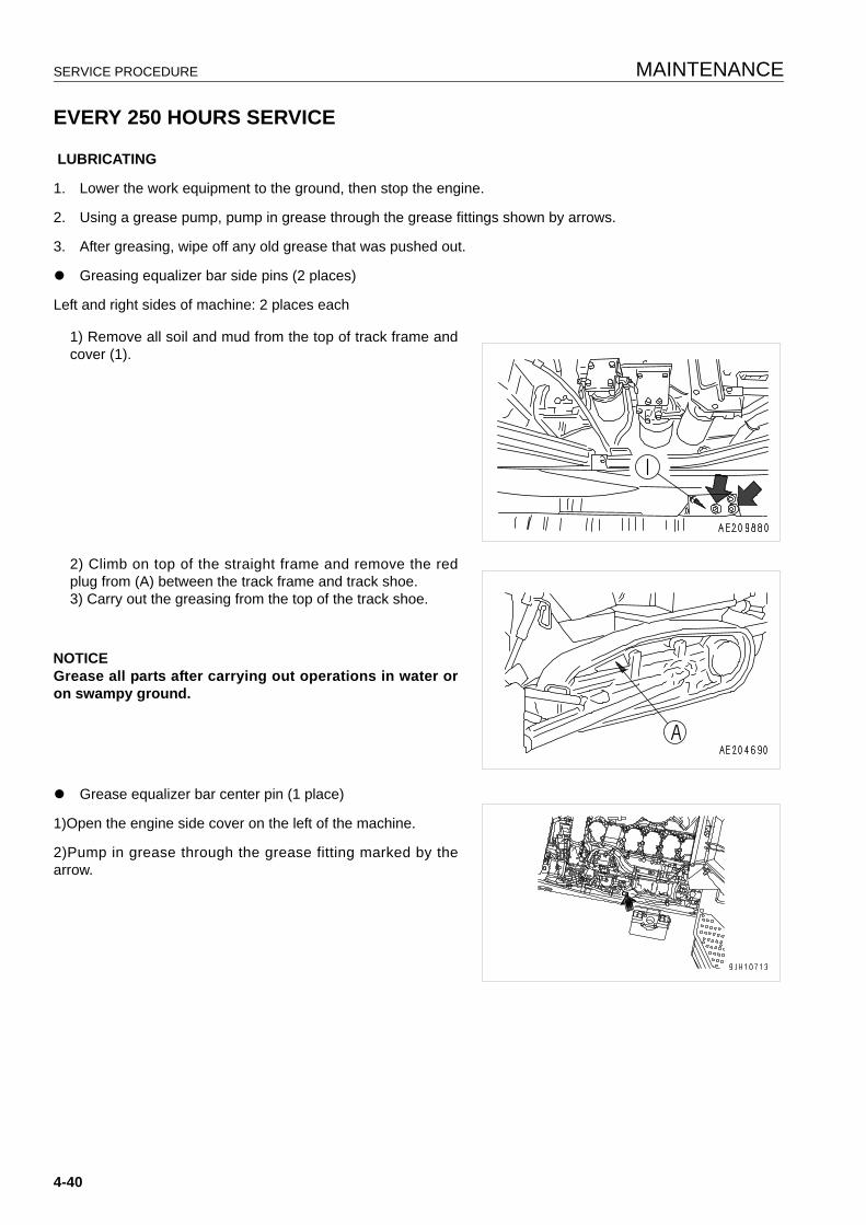
SERVICE PROCEDURE MAINTENANCE
EVERY 250 HOURS SERVICE 4
LUBRICATING
1. Lower the work equipment to the ground, then stop the engine.
2. Using a grease pump, pump in grease through the grease fittings shown by arrows.
3. After greasing, wipe off any old grease that was pushed out.
q Greasing equalizer bar side pins (2 places)
Left and right sides of machine: 2 places each
1) Remove all soil and mud from the top of track frame andcover (1).
2) Climb on top of the straight frame and remove the redplug from (A) between the track frame and track shoe.3) Carry out the greasing from the top of the track shoe.
NOTICEGrease all parts after carrying out operations in water oron swampy ground.
q Grease equalizer bar center pin (1 place)
1)Open the engine side cover on the left of the machine.
2)Pump in grease through the grease fitting marked by thearrow.
4-40
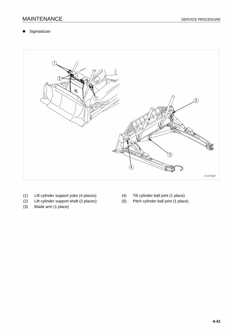
MAINTENANCE SERVICE PROCEDURE
q Sigmadozer
(1) Lift cylinder support yoke (4 places) (4) Tilt cylinder ball joint (1 place)(2) Lift cylinder support shaft (2 places) (5) Pitch cylinder ball joint (1 place)(3) Blade arm (1 place)
4-41
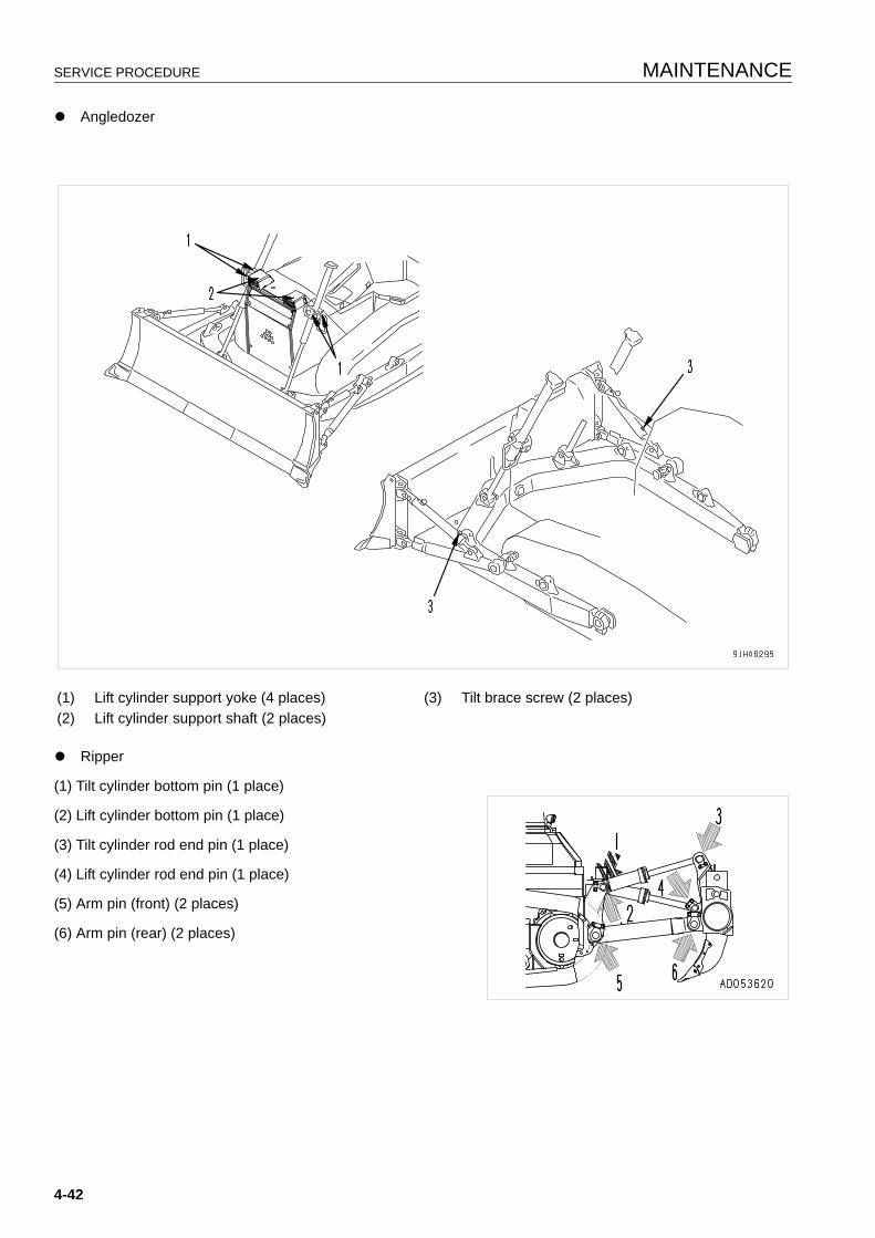
SERVICE PROCEDURE MAINTENANCE
q Angledozer
q Ripper
(1) Tilt cylinder bottom pin (1 place)
(2) Lift cylinder bottom pin (1 place)
(3) Tilt cylinder rod end pin (1 place)
(4) Lift cylinder rod end pin (1 place)
(5) Arm pin (front) (2 places)
(6) Arm pin (rear) (2 places)
(1) Lift cylinder support yoke (4 places) (3) Tilt brace screw (2 places)(2) Lift cylinder support shaft (2 places)
4-42
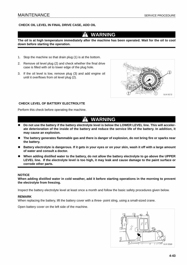
MAINTENANCE SERVICE PROCEDURE
CHECK OIL LEVEL IN FINAL DRIVE CASE, ADD OIL
WARNINGThe oil is at high temperature immediately after the machine has been operated. Wait for the oil to cooldown before starting the operation.
1. Stop the machine so that drain plug (1) is at the bottom.
2. Remove oil level plug (2) and check whether the final drivecase is filled with oil to lower edge of the plug hole.
3. If the oil level is low, remove plug (3) and add engine oiluntil it overflows from oil level plug (2).
CHECK LEVEL OF BATTERY ELECTROLYTE
Perform this check before operating the machine.
WARNINGq Do not use the battery if the battery electrolyte level is below the LOWER LEVEL line. This will acceler-
ate deterioration of the inside of the battery and reduce the service life of the battery. In addition, itmay cause an explosion.
q The battery generates flammable gas and there is danger of explosion, do not bring fire or sparks nearthe battery.
q Battery electrolyte is dangerous. If it gets in your eyes or on your skin, wash it off with a large amountof water and consult a doctor.
q When adding distilled water to the battery, do not allow the battery electrolyte to go above the UPPERLEVEL line. If the electrolyte level is too high, it may leak and cause damage to the paint surface orcorrode other parts.
NOTICEWhen adding distilled water in cold weather, add it before starting operations in the morning to preventthe electrolyte from freezing.
Inspect the battery electrolyte level at least once a month and follow the basic safety procedures given below.
REMARKWhen replacing the battery, lift the battery cover with a three- point sling, using a small-sized crane.
Open battery cover on the left side of the machine.
4-43

SERVICE PROCEDURE MAINTENANCE
WHEN CHECKING ELECTROLYTE LEVEL FROM SIDE OF BATTERY
If it is possible to check the electrolyte level from the side of the battery, check as follows.
1. Use a wet cloth to clean the area around the electrolytelevel lines and check that the electrolyte level is betweenthe UPPER LEVEL (U.L.) and LOWER LEVEL (L.L.) lines.
If the battery is wiped with a dry cloth, static electricity maycause a fire or explosion.
2. If the electrolyte level is below the midway point betweenthe U.L and L.L lines, remove cap (1) and add distilledwater to the U.L line.
3. After adding distilled water, tighten cap (1) securely.
REMARKIf distilled water is added to above the U.L. line, use a syringeto lower the level to the U.L. line. Neutralize the removed fluidwith baking soda (sodium bicarbonate), then flush it away witha large amount of water or consult your Komatsu distributor orbattery maker.
4-44
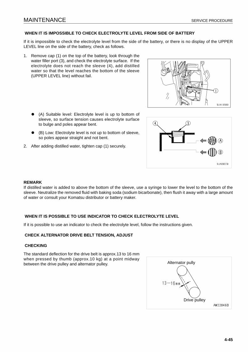
MAINTENANCE SERVICE PROCEDURE
WHEN IT IS IMPOSSIBLE TO CHECK ELECTROLYTE LEVEL FROM SIDE OF BATTERY
If it is impossible to check the electrolyte level from the side of the battery, or there is no display of the UPPERLEVEL line on the side of the battery, check as follows.
1. Remove cap (1) on the top of the battery, look through thewater filler port (3), and check the electrolyte surface. If theelectrolyte does not reach the sleeve (4), add distilledwater so that the level reaches the bottom of the sleeve(UPPER LEVEL line) without fail.
q (A) Suitable level: Electrolyte level is up to bottom ofsleeve, so surface tension causes electrolyte surfaceto bulge and poles appear bent.
q (B) Low: Electrolyte level is not up to bottom of sleeve,so poles appear straight and not bent.
2. After adding distilled water, tighten cap (1) securely.
REMARKIf distilled water is added to above the bottom of the sleeve, use a syringe to lower the level to the bottom of thesleeve. Neutralize the removed fluid with baking soda (sodium bicarbonate), then flush it away with a large amountof water or consult your Komatsu distributor or battery maker.
WHEN IT IS POSSIBLE TO USE INDICATOR TO CHECK ELECTROLYTE LEVEL
If it is possible to use an indicator to check the electrolyte level, follow the instructions given.
CHECK ALTERNATOR DRIVE BELT TENSION, ADJUST
CHECKING
The standard deflection for the drive belt is approx.13 to 16 mmwhen pressed by thumb (approx.10 kg) at a point midwaybetween the drive pulley and alternator pulley. Alternator pully
Drive pulley
4-45
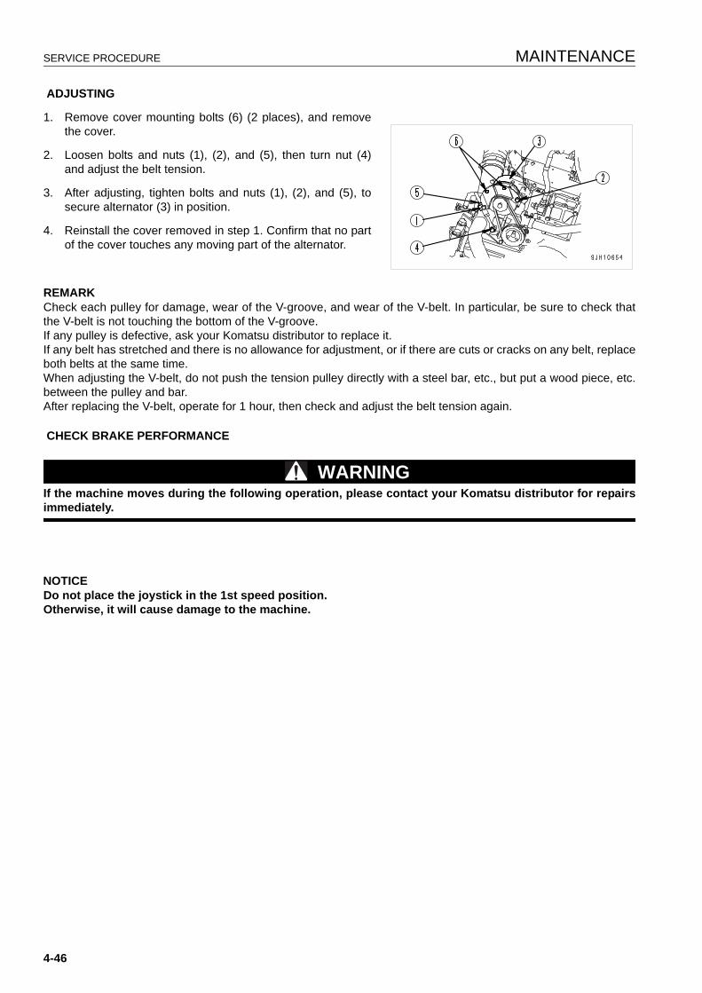
SERVICE PROCEDURE MAINTENANCE
ADJUSTING
1. Remove cover mounting bolts (6) (2 places), and removethe cover.
2. Loosen bolts and nuts (1), (2), and (5), then turn nut (4)and adjust the belt tension.
3. After adjusting, tighten bolts and nuts (1), (2), and (5), tosecure alternator (3) in position.
4. Reinstall the cover removed in step 1. Confirm that no partof the cover touches any moving part of the alternator.
REMARKCheck each pulley for damage, wear of the V-groove, and wear of the V-belt. In particular, be sure to check thatthe V-belt is not touching the bottom of the V-groove.If any pulley is defective, ask your Komatsu distributor to replace it.If any belt has stretched and there is no allowance for adjustment, or if there are cuts or cracks on any belt, replaceboth belts at the same time.When adjusting the V-belt, do not push the tension pulley directly with a steel bar, etc., but put a wood piece, etc.between the pulley and bar.After replacing the V-belt, operate for 1 hour, then check and adjust the belt tension again.
CHECK BRAKE PERFORMANCE
WARNINGIf the machine moves during the following operation, please contact your Komatsu distributor for repairsimmediately.
NOTICEDo not place the joystick in the 1st speed position.Otherwise, it will cause damage to the machine.
4-46
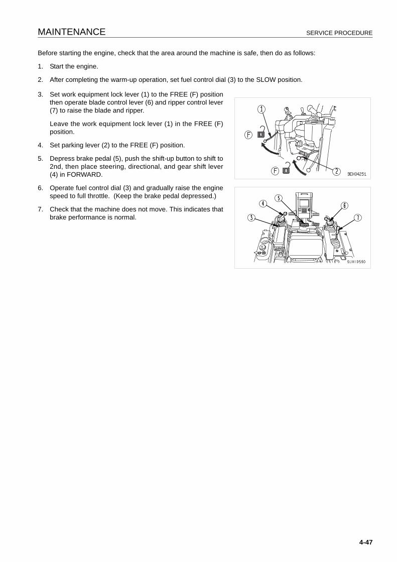
MAINTENANCE SERVICE PROCEDURE
Before starting the engine, check that the area around the machine is safe, then do as follows:
1. Start the engine.
2. After completing the warm-up operation, set fuel control dial (3) to the SLOW position.
3. Set work equipment lock lever (1) to the FREE (F) positionthen operate blade control lever (6) and ripper control lever(7) to raise the blade and ripper.
Leave the work equipment lock lever (1) in the FREE (F)position.
4. Set parking lever (2) to the FREE (F) position.
5. Depress brake pedal (5), push the shift-up button to shift to2nd, then place steering, directional, and gear shift lever(4) in FORWARD.
6. Operate fuel control dial (3) and gradually raise the enginespeed to full throttle. (Keep the brake pedal depressed.)
7. Check that the machine does not move. This indicates thatbrake performance is normal.
4-47
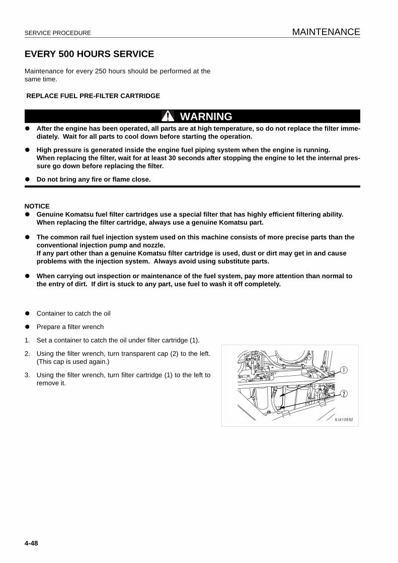
SERVICE PROCEDURE MAINTENANCE
EVERY 500 HOURS SERVICE 4
Maintenance for every 250 hours should be performed at thesame time.
REPLACE FUEL PRE-FILTER CARTRIDGE
WARNINGq After the engine has been operated, all parts are at high temperature, so do not replace the filter imme-
diately. Wait for all parts to cool down before starting the operation.
q High pressure is generated inside the engine fuel piping system when the engine is running.When replacing the filter, wait for at least 30 seconds after stopping the engine to let the internal pres-sure go down before replacing the filter.
q Do not bring any fire or flame close.
NOTICEq Genuine Komatsu fuel filter cartridges use a special filter that has highly efficient filtering ability.
When replacing the filter cartridge, always use a genuine Komatsu part.
q The common rail fuel injection system used on this machine consists of more precise parts than the conventional injection pump and nozzle.If any part other than a genuine Komatsu filter cartridge is used, dust or dirt may get in and cause problems with the injection system. Always avoid using substitute parts.
q When carrying out inspection or maintenance of the fuel system, pay more attention than normal to the entry of dirt. If dirt is stuck to any part, use fuel to wash it off completely.
q Container to catch the oil
q Prepare a filter wrench
1. Set a container to catch the oil under filter cartridge (1).
2. Using the filter wrench, turn transparent cap (2) to the left.(This cap is used again.)
3. Using the filter wrench, turn filter cartridge (1) to the left toremove it.
4-48
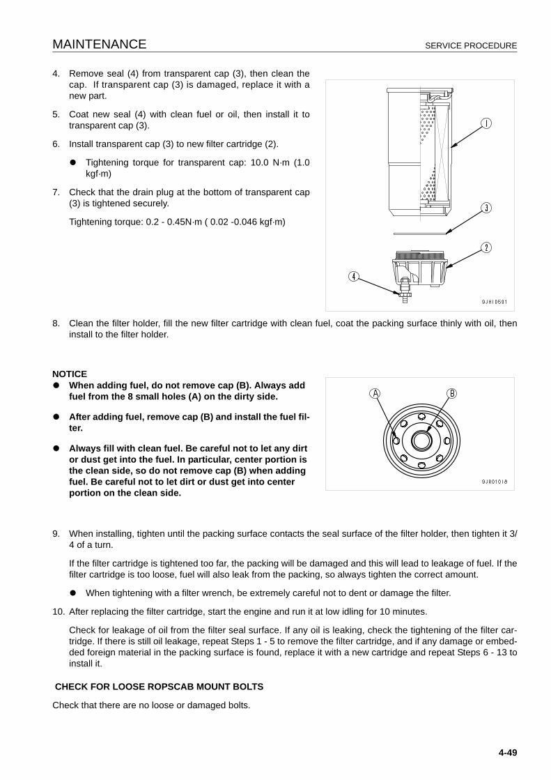
MAINTENANCE SERVICE PROCEDURE
4. Remove seal (4) from transparent cap (3), then clean thecap. If transparent cap (3) is damaged, replace it with anew part.
5. Coat new seal (4) with clean fuel or oil, then install it totransparent cap (3).
6. Install transparent cap (3) to new filter cartridge (2).
q Tightening torque for transparent cap: 10.0 N·m (1.0kgf·m)
7. Check that the drain plug at the bottom of transparent cap(3) is tightened securely.
Tightening torque: 0.2 - 0.45N·m ( 0.02 -0.046 kgf·m)
8. Clean the filter holder, fill the new filter cartridge with clean fuel, coat the packing surface thinly with oil, theninstall to the filter holder.
NOTICEq When adding fuel, do not remove cap (B). Always add
fuel from the 8 small holes (A) on the dirty side.
q After adding fuel, remove cap (B) and install the fuel fil-ter.
q Always fill with clean fuel. Be careful not to let any dirt or dust get into the fuel. In particular, center portion is the clean side, so do not remove cap (B) when adding fuel. Be careful not to let dirt or dust get into center portion on the clean side.
9. When installing, tighten until the packing surface contacts the seal surface of the filter holder, then tighten it 3/4 of a turn.
If the filter cartridge is tightened too far, the packing will be damaged and this will lead to leakage of fuel. If thefilter cartridge is too loose, fuel will also leak from the packing, so always tighten the correct amount.
q When tightening with a filter wrench, be extremely careful not to dent or damage the filter.
10. After replacing the filter cartridge, start the engine and run it at low idling for 10 minutes.
Check for leakage of oil from the filter seal surface. If any oil is leaking, check the tightening of the filter car-tridge. If there is still oil leakage, repeat Steps 1 - 5 to remove the filter cartridge, and if any damage or embed-ded foreign material in the packing surface is found, replace it with a new cartridge and repeat Steps 6 - 13 toinstall it.
CHECK FOR LOOSE ROPSCAB MOUNT BOLTS
Check that there are no loose or damaged bolts.
4-49
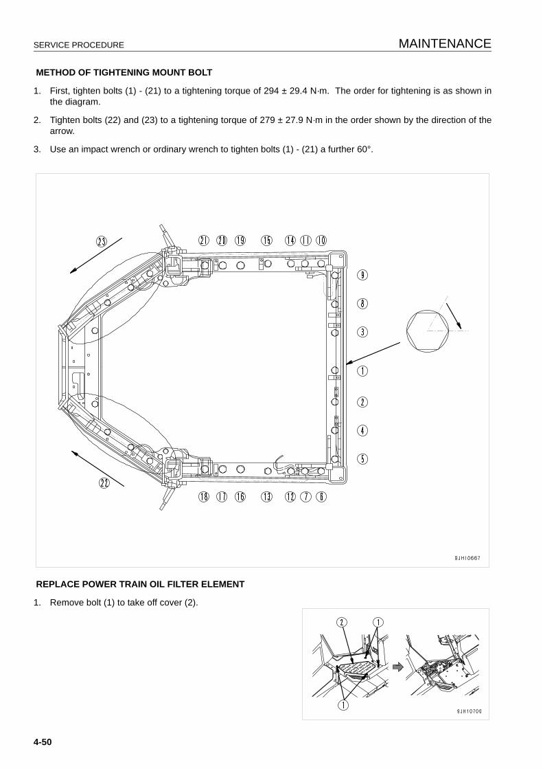
SERVICE PROCEDURE MAINTENANCE
METHOD OF TIGHTENING MOUNT BOLT
1. First, tighten bolts (1) - (21) to a tightening torque of 294 ± 29.4 N·m. The order for tightening is as shown inthe diagram.
2. Tighten bolts (22) and (23) to a tightening torque of 279 ± 27.9 N·m in the order shown by the direction of thearrow.
3. Use an impact wrench or ordinary wrench to tighten bolts (1) - (21) a further 60°.
REPLACE POWER TRAIN OIL FILTER ELEMENT
1. Remove bolt (1) to take off cover (2).
4-50
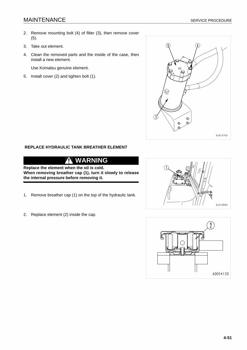
MAINTENANCE SERVICE PROCEDURE
2. Remove mounting bolt (4) of filter (3), then remove cover(5).
3. Take out element.
4. Clean the removed parts and the inside of the case, theninstall a new element.
Use Komatsu genuine element.
5. Install cover (2) and tighten bolt (1).
REPLACE HYDRAULIC TANK BREATHER ELEMENT
WARNINGReplace the element when the oil is cold.When removing breather cap (1), turn it slowly to releasethe internal pressure before removing it.
1. Remove breather cap (1) on the top of the hydraulic tank.
2. Replace element (2) inside the cap.
4-51
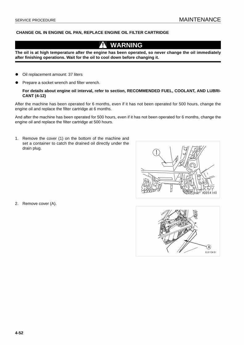
SERVICE PROCEDURE MAINTENANCE
CHANGE OIL IN ENGINE OIL PAN, REPLACE ENGINE OIL FILTER CARTRIDGE
WARNINGThe oil is at high temperature after the engine has been operated, so never change the oil immediatelyafter finishing operations. Wait for the oil to cool down before changing it.
q Oil replacement amount: 37 liters
q Prepare a socket wrench and filter wrench.
For details about engine oil interval, refer to section, RECOMMENDED FUEL, COOLANT, AND LUBRI-CANT (4-12)
After the machine has been operated for 6 months, even if it has not been operated for 500 hours, change theengine oil and replace the filter cartridge at 6 months.
And after the machine has been operated for 500 hours, even if it has not been operated for 6 months, change theengine oil and replace the filter cartridge at 500 hours.
1. Remove the cover (1) on the bottom of the machine andset a container to catch the drained oil directly under thedrain plug.
2. Remove cover (A).
4-52
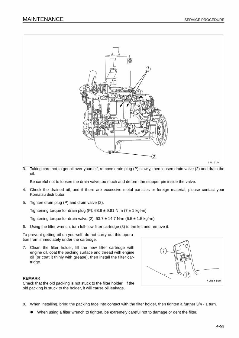
MAINTENANCE SERVICE PROCEDURE
3. Taking care not to get oil over yourself, remove drain plug (P) slowly, then loosen drain valve (2) and drain theoil.
Be careful not to loosen the drain valve too much and deform the stopper pin inside the valve.
4. Check the drained oil, and if there are excessive metal particles or foreign material, please contact yourKomatsu distributor.
5. Tighten drain plug (P) and drain valve (2).
Tightening torque for drain plug (P): 68.6 ± 9.81 N·m (7 ± 1 kgf·m)
Tightening torque for drain valve (2): 63.7 ± 14.7 N·m (6.5 ± 1.5 kgf·m)
6. Using the filter wrench, turn full-flow filter cartridge (3) to the left and remove it.
To prevent getting oil on yourself, do not carry out this opera-tion from immediately under the cartridge.
7. Clean the filter holder, fill the new filter cartridge withengine oil, coat the packing surface and thread with engineoil (or coat it thinly with grease), then install the filter car-tridge.
REMARKCheck that the old packing is not stuck to the filter holder. If theold packing is stuck to the holder, it will cause oil leakage.
8. When installing, bring the packing face into contact with the filter holder, then tighten a further 3/4 - 1 turn.
q When using a filter wrench to tighten, be extremely careful not to damage or dent the filter.
4-53

SERVICE PROCEDURE MAINTENANCE
9. After replacing the filter cartridge, add oil through oil filler port (F) so that the oil level is between the H and Lmarks on dipstick (G).
10. Run the engine at idling for a short time, then stop the engine, and check that the oil level is between the Hand L marks on the dipstick. For details, see “CHECK OIL LEVEL IN ENGINE OIL PAN, ADD OIL (3-83)“.
4-54

MAINTENANCE SERVICE PROCEDURE
EVERY 1000 HOURS SERVICE 4
Maintenance for every 250 and 500 hours should be performedat the same time.
CHANGE OIL IN POWER TRAIN CASE, WASH STRAINERS (POWER TRAIN PUMP STRAINER, SCAVENG-ING PUMP STRAINER)
WARNINGq The oil is at high temperature immediately after operations, so wait for the temperature to go down
before starting the operation.
q The undercover is heavy. Do not go directly under the cover when opening or closing it. When remov-ing bolts (5), carry out the operation at the rear of the point immediately under the cover so that it ispossible to escape at any time.Prepare the following.
q Oil replacement amount: 146 liters
1. Remove drain cover (1) on the left side at the bottom of thepower train case, pull out drain hose (2) from the takeoffport, then loosen drain plug (P1) and drain the oil.
After draining the oil, tighten drain plug (P1).
Do not remove drain plug (P1).
2. Remove inspection cover (3) of the undercover on the bot-tom rear of the machine as follows.
1) Remove 2 bolts (4) on the machine front end.
2) Hold down cover (3) and remove 2 bolts (5) on themachine rear end gradually. (Rainwater or other accumu-lated water may flow out, so be careful.)
3) Lower cover (3) gradually and open it. (The front side ofthe cover is hinged.)
The strainer can be seen at top portion P.
3. Remove drain plug (P2) in the strainer cover, and drain theoil (approx. 4 liters) collected inside the piping.
4. Loosen mounting bolt (6) of the power train strainer, andremove cover (7).
5. Remove spring (8), then remove strainer (9).
6. Remove any dirt stuck to strainer (9), then wash it in cleandiesel oil or flushing oil. Wash the removed parts and theinside of the case at the same time.
(A): Front of machine
4-55
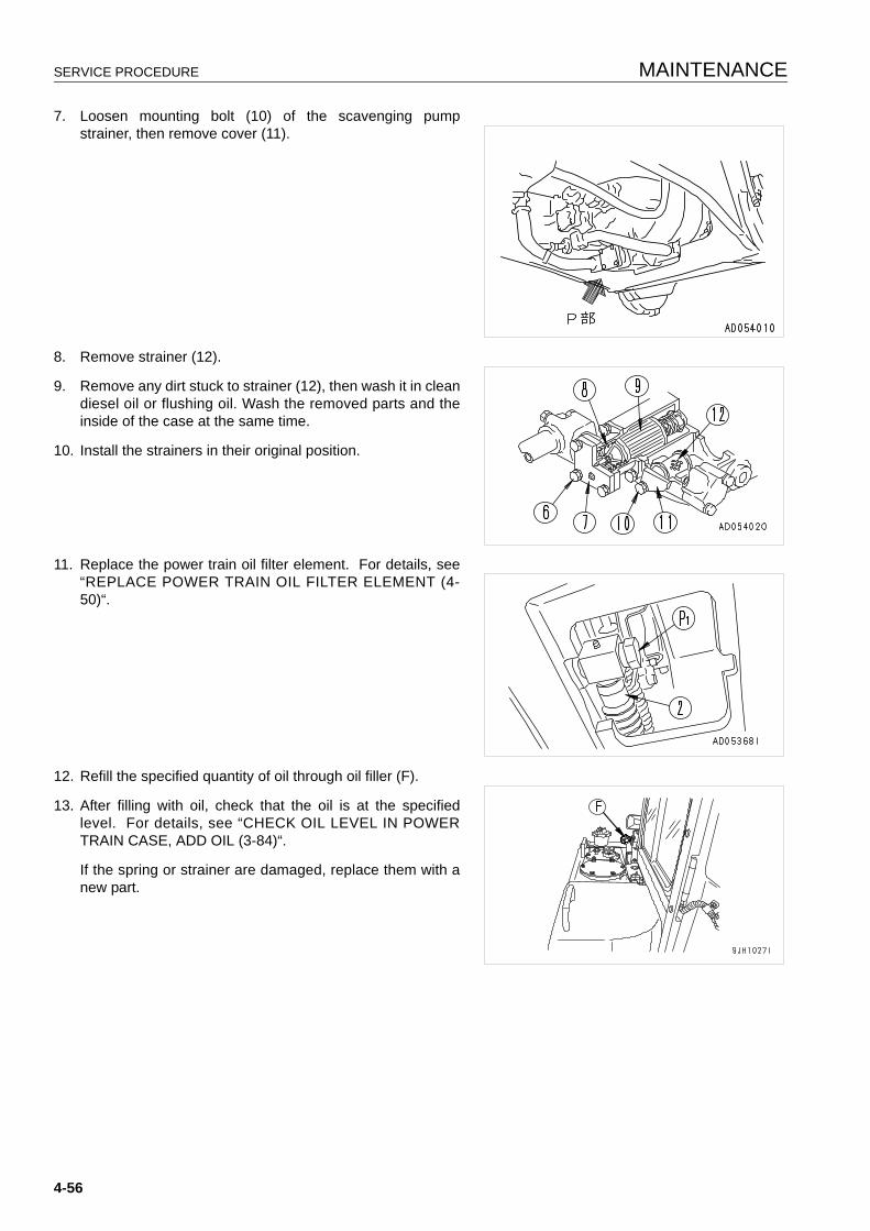
SERVICE PROCEDURE MAINTENANCE
7. Loosen mounting bolt (10) of the scavenging pumpstrainer, then remove cover (11).
8. Remove strainer (12).
9. Remove any dirt stuck to strainer (12), then wash it in cleandiesel oil or flushing oil. Wash the removed parts and theinside of the case at the same time.
10. Install the strainers in their original position.
11. Replace the power train oil filter element. For details, see“REPLACE POWER TRAIN OIL FILTER ELEMENT (4-50)“.
12. Refill the specified quantity of oil through oil filler (F).
13. After filling with oil, check that the oil is at the specifiedlevel. For details, see “CHECK OIL LEVEL IN POWERTRAIN CASE, ADD OIL (3-84)“.
If the spring or strainer are damaged, replace them with anew part.
4-56
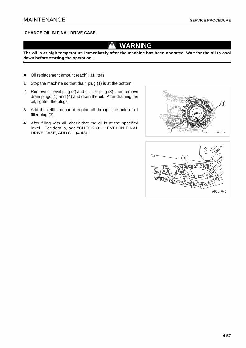
MAINTENANCE SERVICE PROCEDURE
CHANGE OIL IN FINAL DRIVE CASE
WARNINGThe oil is at high temperature immediately after the machine has been operated. Wait for the oil to cooldown before starting the operation.
q Oil replacement amount (each): 31 liters
1. Stop the machine so that drain plug (1) is at the bottom.
2. Remove oil level plug (2) and oil filler plug (3), then removedrain plugs (1) and (4) and drain the oil. After draining theoil, tighten the plugs.
3. Add the refill amount of engine oil through the hole of oilfiller plug (3).
4. After filling with oil, check that the oil is at the specifiedlevel. For details, see “CHECK OIL LEVEL IN FINALDRIVE CASE, ADD OIL (4-43)“.
4-57
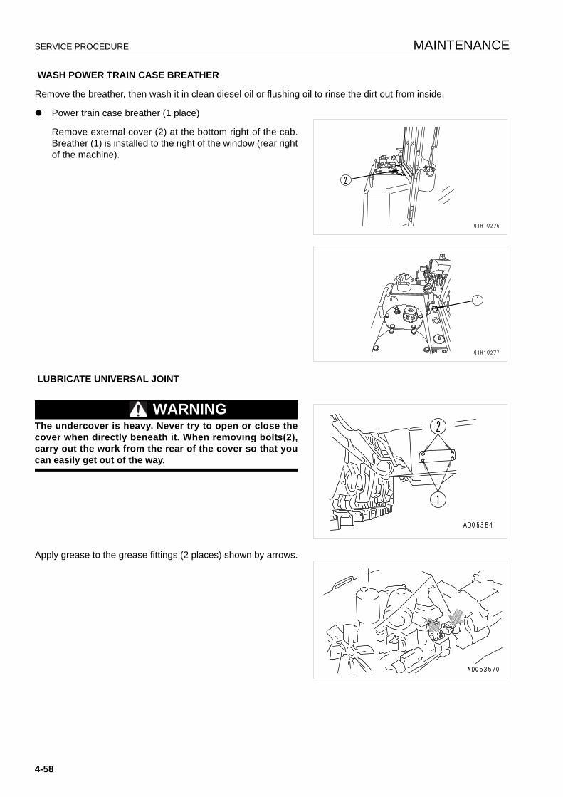
SERVICE PROCEDURE MAINTENANCE
WASH POWER TRAIN CASE BREATHER
Remove the breather, then wash it in clean diesel oil or flushing oil to rinse the dirt out from inside.
q Power train case breather (1 place)
Remove external cover (2) at the bottom right of the cab.Breather (1) is installed to the right of the window (rear rightof the machine).
LUBRICATE UNIVERSAL JOINT
WARNINGThe undercover is heavy. Never try to open or close thecover when directly beneath it. When removing bolts(2),carry out the work from the rear of the cover so that youcan easily get out of the way.
Apply grease to the grease fittings (2 places) shown by arrows.
4-58
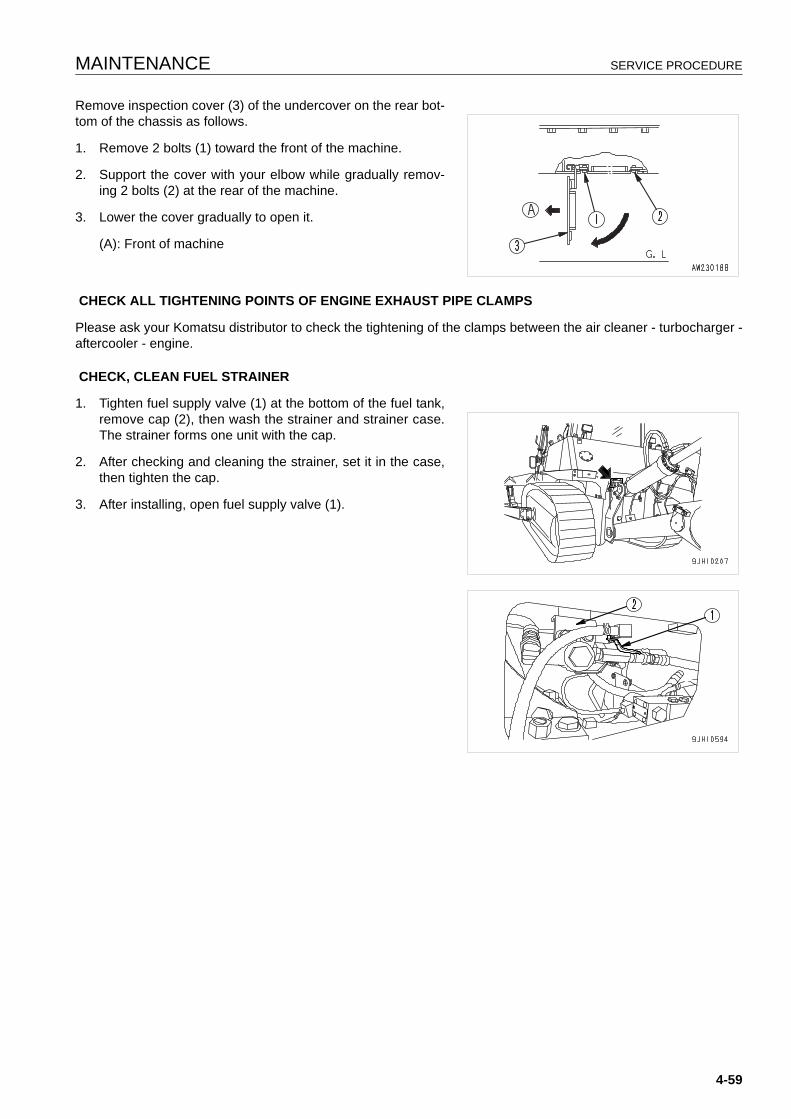
MAINTENANCE SERVICE PROCEDURE
Remove inspection cover (3) of the undercover on the rear bot-tom of the chassis as follows.
1. Remove 2 bolts (1) toward the front of the machine.
2. Support the cover with your elbow while gradually remov-ing 2 bolts (2) at the rear of the machine.
3. Lower the cover gradually to open it.
(A): Front of machine
CHECK ALL TIGHTENING POINTS OF ENGINE EXHAUST PIPE CLAMPS
Please ask your Komatsu distributor to check the tightening of the clamps between the air cleaner - turbocharger -aftercooler - engine.
CHECK, CLEAN FUEL STRAINER
1. Tighten fuel supply valve (1) at the bottom of the fuel tank,remove cap (2), then wash the strainer and strainer case.The strainer forms one unit with the cap.
2. After checking and cleaning the strainer, set it in the case,then tighten the cap.
3. After installing, open fuel supply valve (1).
4-59
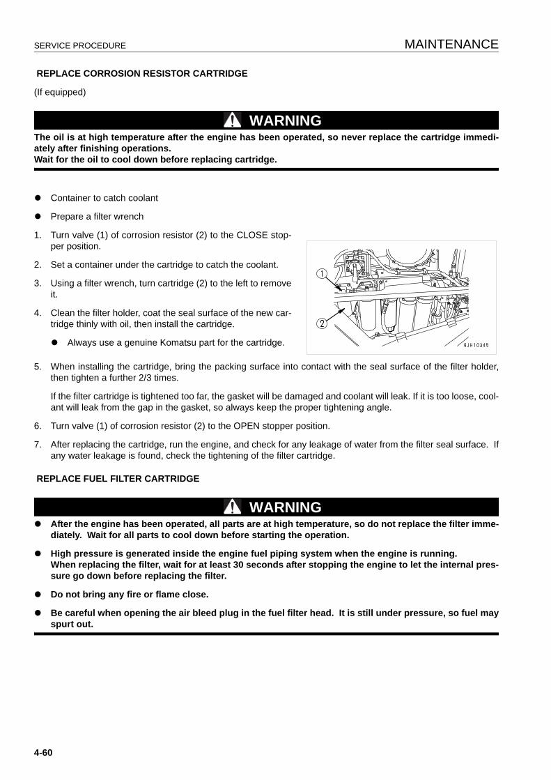
SERVICE PROCEDURE MAINTENANCE
REPLACE CORROSION RESISTOR CARTRIDGE
(If equipped)
WARNINGThe oil is at high temperature after the engine has been operated, so never replace the cartridge immedi-ately after finishing operations.Wait for the oil to cool down before replacing cartridge.
q Container to catch coolant
q Prepare a filter wrench
1. Turn valve (1) of corrosion resistor (2) to the CLOSE stop-per position.
2. Set a container under the cartridge to catch the coolant.
3. Using a filter wrench, turn cartridge (2) to the left to removeit.
4. Clean the filter holder, coat the seal surface of the new car-tridge thinly with oil, then install the cartridge.
q Always use a genuine Komatsu part for the cartridge.
5. When installing the cartridge, bring the packing surface into contact with the seal surface of the filter holder,then tighten a further 2/3 times.
If the filter cartridge is tightened too far, the gasket will be damaged and coolant will leak. If it is too loose, cool-ant will leak from the gap in the gasket, so always keep the proper tightening angle.
6. Turn valve (1) of corrosion resistor (2) to the OPEN stopper position.
7. After replacing the cartridge, run the engine, and check for any leakage of water from the filter seal surface. Ifany water leakage is found, check the tightening of the filter cartridge.
REPLACE FUEL FILTER CARTRIDGE
WARNINGq After the engine has been operated, all parts are at high temperature, so do not replace the filter imme-
diately. Wait for all parts to cool down before starting the operation.
q High pressure is generated inside the engine fuel piping system when the engine is running.When replacing the filter, wait for at least 30 seconds after stopping the engine to let the internal pres-sure go down before replacing the filter.
q Do not bring any fire or flame close.
q Be careful when opening the air bleed plug in the fuel filter head. It is still under pressure, so fuel mayspurt out.
4-60
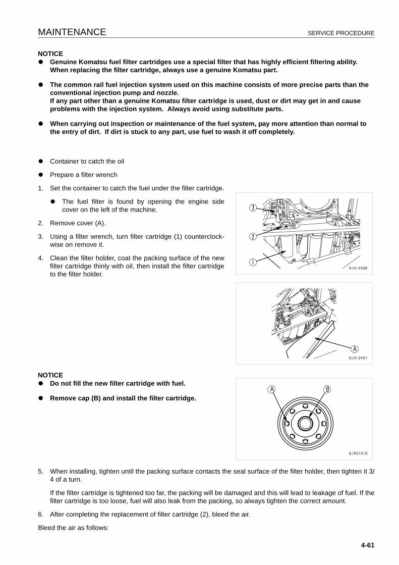
MAINTENANCE SERVICE PROCEDURE
NOTICEq Genuine Komatsu fuel filter cartridges use a special filter that has highly efficient filtering ability.
When replacing the filter cartridge, always use a genuine Komatsu part.
q The common rail fuel injection system used on this machine consists of more precise parts than the conventional injection pump and nozzle.If any part other than a genuine Komatsu filter cartridge is used, dust or dirt may get in and cause problems with the injection system. Always avoid using substitute parts.
q When carrying out inspection or maintenance of the fuel system, pay more attention than normal to the entry of dirt. If dirt is stuck to any part, use fuel to wash it off completely.
q Container to catch the oil
q Prepare a filter wrench
1. Set the container to catch the fuel under the filter cartridge.
q The fuel filter is found by opening the engine sidecover on the left of the machine.
2. Remove cover (A).
3. Using a filter wrench, turn filter cartridge (1) counterclock-wise on remove it.
4. Clean the filter holder, coat the packing surface of the newfilter cartridge thinly with oil, then install the filter cartridgeto the filter holder.
NOTICEq Do not fill the new filter cartridge with fuel.
q Remove cap (B) and install the filter cartridge.
5. When installing, tighten until the packing surface contacts the seal surface of the filter holder, then tighten it 3/4 of a turn.
If the filter cartridge is tightened too far, the packing will be damaged and this will lead to leakage of fuel. If thefilter cartridge is too loose, fuel will also leak from the packing, so always tighten the correct amount.
6. After completing the replacement of filter cartridge (2), bleed the air.
Bleed the air as follows:
4-61
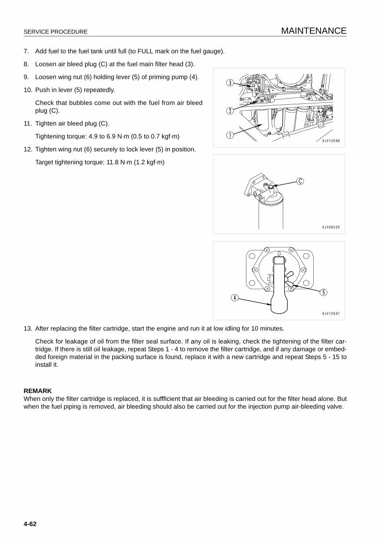
SERVICE PROCEDURE MAINTENANCE
7. Add fuel to the fuel tank until full (to FULL mark on the fuel gauge).
8. Loosen air bleed plug (C) at the fuel main filter head (3).
9. Loosen wing nut (6) holding lever (5) of priming pump (4).
10. Push in lever (5) repeatedly.
Check that bubbles come out with the fuel from air bleedplug (C).
11. Tighten air bleed plug (C).
Tightening torque: 4.9 to 6.9 N·m (0.5 to 0.7 kgf·m)
12. Tighten wing nut (6) securely to lock lever (5) in position.
Target tightening torque: 11.8 N·m (1.2 kgf·m)
13. After replacing the filter cartridge, start the engine and run it at low idling for 10 minutes.
Check for leakage of oil from the filter seal surface. If any oil is leaking, check the tightening of the filter car-tridge. If there is still oil leakage, repeat Steps 1 - 4 to remove the filter cartridge, and if any damage or embed-ded foreign material in the packing surface is found, replace it with a new cartridge and repeat Steps 5 - 15 toinstall it.
REMARKWhen only the filter cartridge is replaced, it is suffficient that air bleeding is carried out for the filter head alone. Butwhen the fuel piping is removed, air bleeding should also be carried out for the injection pump air-bleeding valve.
4-62
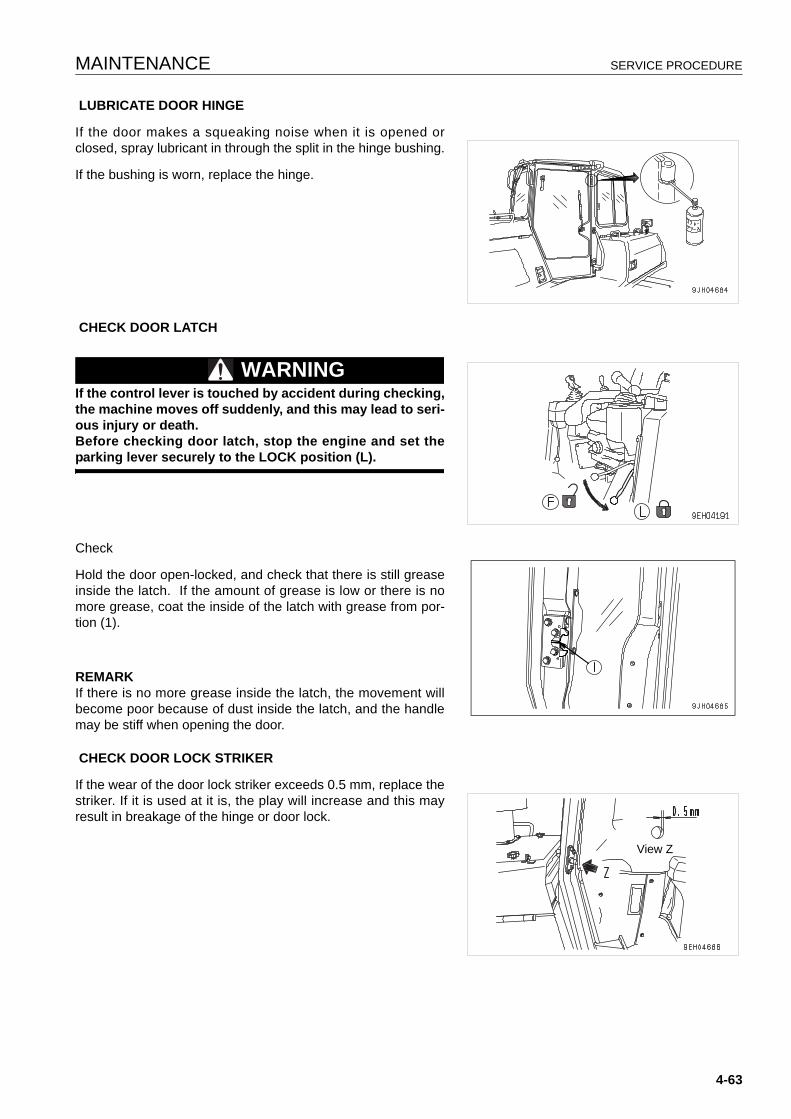
MAINTENANCE SERVICE PROCEDURE
LUBRICATE DOOR HINGE
If the door makes a squeaking noise when it is opened orclosed, spray lubricant in through the split in the hinge bushing.
If the bushing is worn, replace the hinge.
CHECK DOOR LATCH
WARNINGIf the control lever is touched by accident during checking,the machine moves off suddenly, and this may lead to seri-ous injury or death.Before checking door latch, stop the engine and set theparking lever securely to the LOCK position (L).
Check
Hold the door open-locked, and check that there is still greaseinside the latch. If the amount of grease is low or there is nomore grease, coat the inside of the latch with grease from por-tion (1).
REMARKIf there is no more grease inside the latch, the movement willbecome poor because of dust inside the latch, and the handlemay be stiff when opening the door.
CHECK DOOR LOCK STRIKER
If the wear of the door lock striker exceeds 0.5 mm, replace thestriker. If it is used at it is, the play will increase and this mayresult in breakage of the hinge or door lock.
View Z
4-63

SERVICE PROCEDURE MAINTENANCE
REPLACE DOOR DAMPER
If the depth (A) of the door damper rubber (1) groove is lessthan 2 mm, replace the damper.
There are two dampers each at the top and bottom on the leftand right doors.
4-64
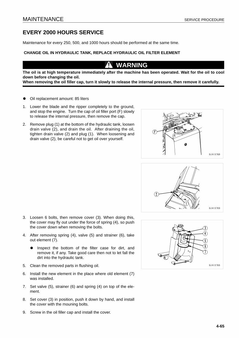
MAINTENANCE SERVICE PROCEDURE
EVERY 2000 HOURS SERVICE 4
Maintenance for every 250, 500, and 1000 hours should be performed at the same time.
CHANGE OIL IN HYDRAULIC TANK, REPLACE HYDRAULIC OIL FILTER ELEMENT
WARNINGThe oil is at high temperature immediately after the machine has been operated. Wait for the oil to cooldown before changing the oil.When removing the oil filler cap, turn it slowly to release the internal pressure, then remove it carefully.
q Oil replacement amount: 85 liters
1. Lower the blade and the ripper completely to the ground,and stop the engine. Turn the cap of oil filler port (F) slowlyto release the internal pressure, then remove the cap.
2. Remove plug (1) at the bottom of the hydraulic tank, loosendrain valve (2), and drain the oil. After draining the oil,tighten drain valve (2) and plug (1). When loosening anddrain valve (2), be careful not to get oil over yourself.
3. Loosen 6 bolts, then remove cover (3). When doing this,the cover may fly out under the force of spring (4), so pushthe cover down when removing the bolts.
4. After removing spring (4), valve (5) and strainer (6), takeout element (7).
q Inspect the bottom of the filter case for dirt, andremove it, if any. Take good care then not to let fall thedirt into the hydraulic tank.
5. Clean the removed parts in flushing oil.
6. Install the new element in the place where old element (7)was installed.
7. Set valve (5), strainer (6) and spring (4) on top of the ele-ment.
8. Set cover (3) in position, push it down by hand, and installthe cover with the mouning bolts.
9. Screw in the oil filler cap and install the cover.
4-65
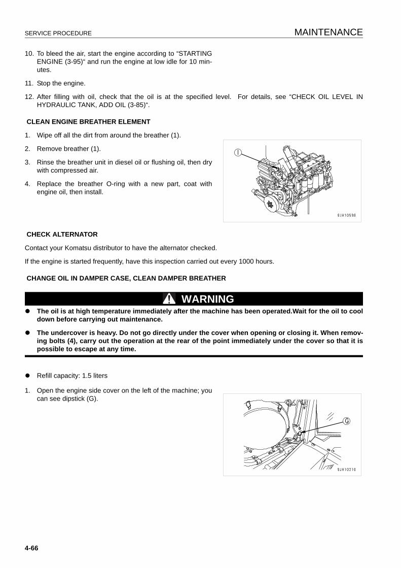
SERVICE PROCEDURE MAINTENANCE
10. To bleed the air, start the engine according to “STARTINGENGINE (3-95)“ and run the engine at low idle for 10 min-utes.
11. Stop the engine.
12. After filling with oil, check that the oil is at the specified level. For details, see “CHECK OIL LEVEL INHYDRAULIC TANK, ADD OIL (3-85)“.
CLEAN ENGINE BREATHER ELEMENT
1. Wipe off all the dirt from around the breather (1).
2. Remove breather (1).
3. Rinse the breather unit in diesel oil or flushing oil, then drywith compressed air.
4. Replace the breather O-ring with a new part, coat withengine oil, then install.
CHECK ALTERNATOR
Contact your Komatsu distributor to have the alternator checked.
If the engine is started frequently, have this inspection carried out every 1000 hours.
CHANGE OIL IN DAMPER CASE, CLEAN DAMPER BREATHER
WARNINGq The oil is at high temperature immediately after the machine has been operated.Wait for the oil to cool
down before carrying out maintenance.
q The undercover is heavy. Do not go directly under the cover when opening or closing it. When remov-ing bolts (4), carry out the operation at the rear of the point immediately under the cover so that it ispossible to escape at any time.
q Refill capacity: 1.5 liters
1. Open the engine side cover on the left of the machine; youcan see dipstick (G).
4-66
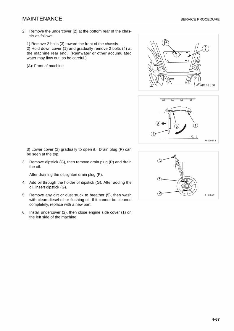
MAINTENANCE SERVICE PROCEDURE
2. Remove the undercover (2) at the bottom rear of the chas-sis as follows.
1) Remove 2 bolts (3) toward the front of the chassis.2) Hold down cover (1) and gradually remove 2 bolts (4) atthe machine rear end. (Rainwater or other accumulatedwater may flow out, so be careful.)
(A): Front of machine
3) Lower cover (2) gradually to open it. Drain plug (P) canbe seen at the top.
3. Remove dipstick (G), then remove drain plug (P) and drainthe oil.
After draining the oil,tighten drain plug (P).
4. Add oil through the holder of dipstick (G). After adding theoil, insert dipstick (G).
5. Remove any dirt or dust stuck to breather (5), then washwith clean diesel oil or flushing oil. If it cannot be cleanedcompletely, replace with a new part.
6. Install undercover (2), then close engine side cover (1) onthe left side of the machine.
4-67
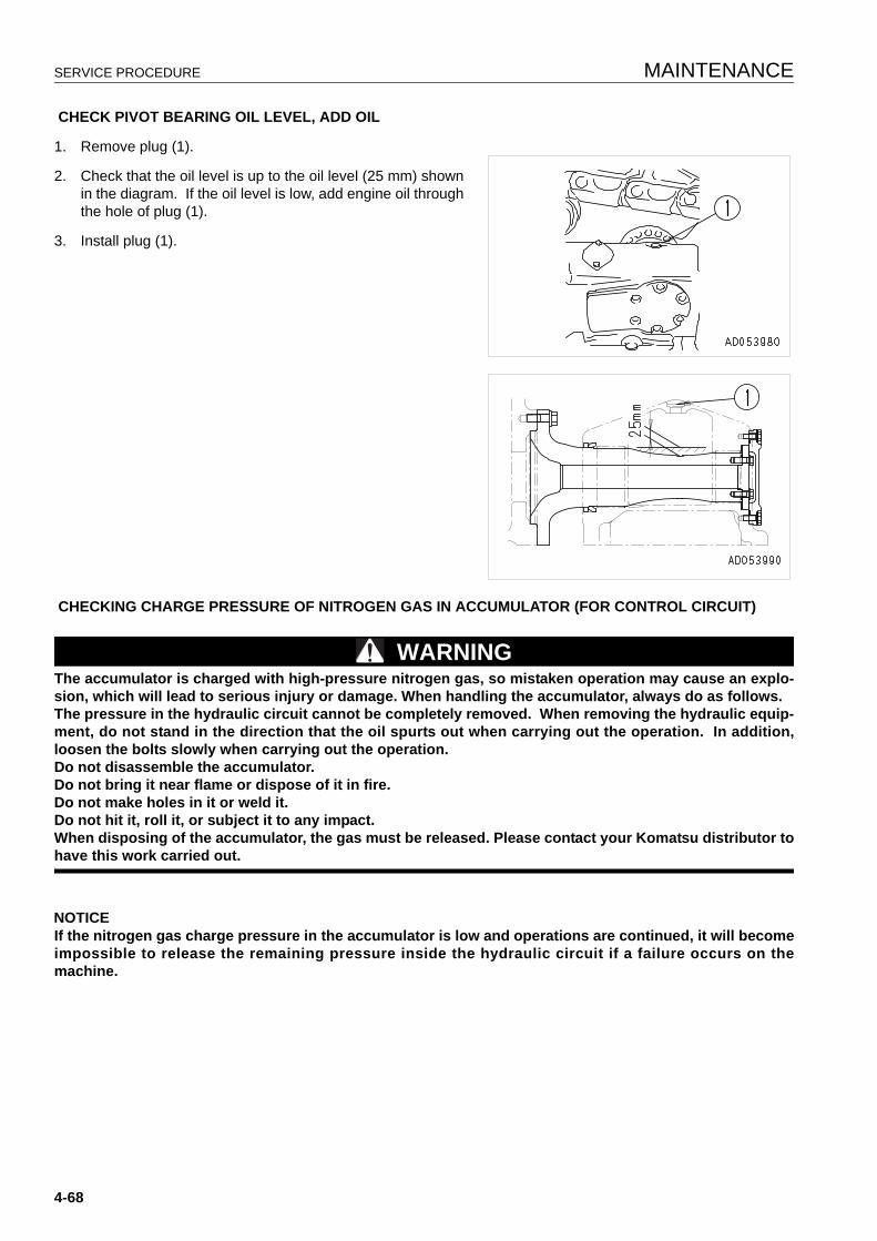
SERVICE PROCEDURE MAINTENANCE
CHECK PIVOT BEARING OIL LEVEL, ADD OIL
1. Remove plug (1).
2. Check that the oil level is up to the oil level (25 mm) shownin the diagram. If the oil level is low, add engine oil throughthe hole of plug (1).
3. Install plug (1).
CHECKING CHARGE PRESSURE OF NITROGEN GAS IN ACCUMULATOR (FOR CONTROL CIRCUIT)
WARNINGThe accumulator is charged with high-pressure nitrogen gas, so mistaken operation may cause an explo-sion, which will lead to serious injury or damage. When handling the accumulator, always do as follows.The pressure in the hydraulic circuit cannot be completely removed. When removing the hydraulic equip-ment, do not stand in the direction that the oil spurts out when carrying out the operation. In addition,loosen the bolts slowly when carrying out the operation.Do not disassemble the accumulator.Do not bring it near flame or dispose of it in fire.Do not make holes in it or weld it.Do not hit it, roll it, or subject it to any impact.When disposing of the accumulator, the gas must be released. Please contact your Komatsu distributor tohave this work carried out.
NOTICEIf the nitrogen gas charge pressure in the accumulator is low and operations are continued, it will becomeimpossible to release the remaining pressure inside the hydraulic circuit if a failure occurs on themachine.
4-68
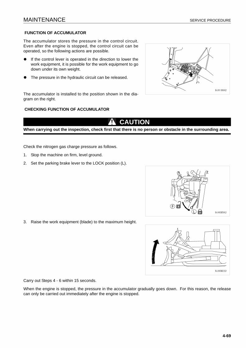
MAINTENANCE SERVICE PROCEDURE
FUNCTION OF ACCUMULATOR
The accumulator stores the pressure in the control circuit.Even after the engine is stopped, the control circuit can beoperated, so the following actions are possible.
q If the control lever is operated in the direction to lower thework equipment, it is possible for the work equipment to godown under its own weight.
q The pressure in the hydraulic circuit can be released.
The accumulator is installed to the position shown in the dia-gram on the right.
CHECKING FUNCTION OF ACCUMULATOR
CAUTIONWhen carrying out the inspection, check first that there is no person or obstacle in the surrounding area.
Check the nitrogen gas charge pressure as follows.
1. Stop the machine on firm, level ground.
2. Set the parking brake lever to the LOCK position (L).
3. Raise the work equipment (blade) to the maximum height.
Carry out Steps 4 - 6 within 15 seconds.
When the engine is stopped, the pressure in the accumulator gradually goes down. For this reason, the releasecan only be carried out immediately after the engine is stopped.
4-69
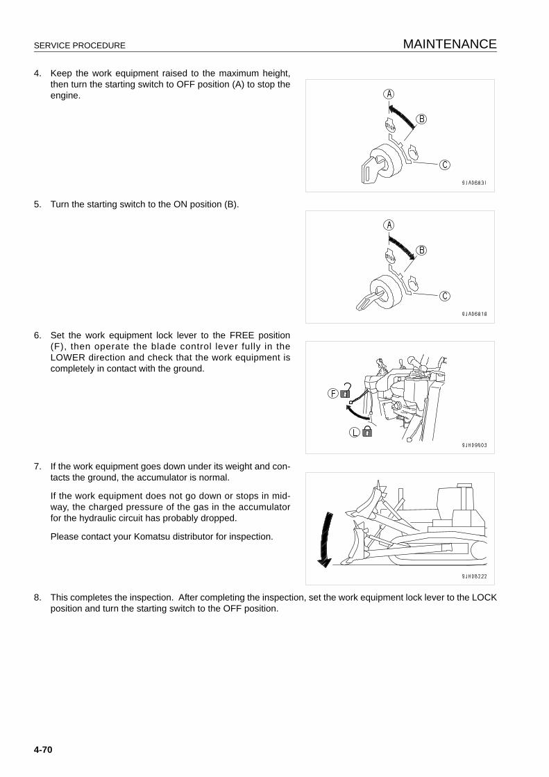
SERVICE PROCEDURE MAINTENANCE
4. Keep the work equipment raised to the maximum height,then turn the starting switch to OFF position (A) to stop theengine.
5. Turn the starting switch to the ON position (B).
6. Set the work equipment lock lever to the FREE position(F), then operate the blade control lever fully in theLOWER direction and check that the work equipment iscompletely in contact with the ground.
7. If the work equipment goes down under its weight and con-tacts the ground, the accumulator is normal.
If the work equipment does not go down or stops in mid-way, the charged pressure of the gas in the accumulatorfor the hydraulic circuit has probably dropped.
Please contact your Komatsu distributor for inspection.
8. This completes the inspection. After completing the inspection, set the work equipment lock lever to the LOCKposition and turn the starting switch to the OFF position.
4-70
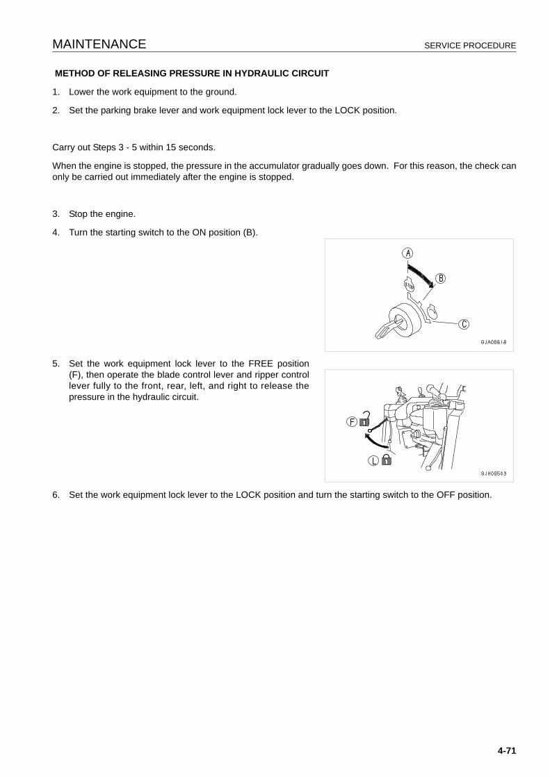
MAINTENANCE SERVICE PROCEDURE
METHOD OF RELEASING PRESSURE IN HYDRAULIC CIRCUIT
1. Lower the work equipment to the ground.
2. Set the parking brake lever and work equipment lock lever to the LOCK position.
Carry out Steps 3 - 5 within 15 seconds.
When the engine is stopped, the pressure in the accumulator gradually goes down. For this reason, the check canonly be carried out immediately after the engine is stopped.
3. Stop the engine.
4. Turn the starting switch to the ON position (B).
5. Set the work equipment lock lever to the FREE position(F), then operate the blade control lever and ripper controllever fully to the front, rear, left, and right to release thepressure in the hydraulic circuit.
6. Set the work equipment lock lever to the LOCK position and turn the starting switch to the OFF position.
4-71
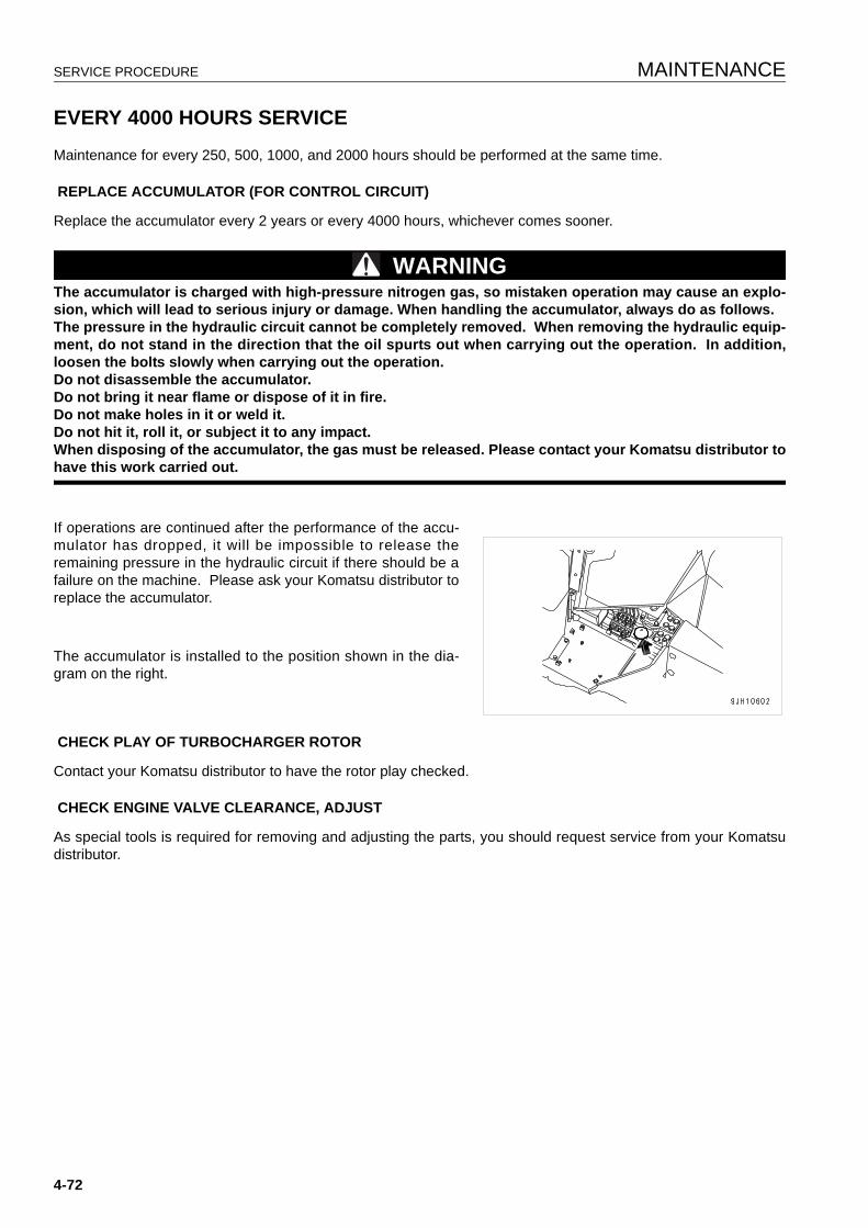
SERVICE PROCEDURE MAINTENANCE
EVERY 4000 HOURS SERVICE 4
Maintenance for every 250, 500, 1000, and 2000 hours should be performed at the same time.
REPLACE ACCUMULATOR (FOR CONTROL CIRCUIT)
Replace the accumulator every 2 years or every 4000 hours, whichever comes sooner.
WARNINGThe accumulator is charged with high-pressure nitrogen gas, so mistaken operation may cause an explo-sion, which will lead to serious injury or damage. When handling the accumulator, always do as follows.The pressure in the hydraulic circuit cannot be completely removed. When removing the hydraulic equip-ment, do not stand in the direction that the oil spurts out when carrying out the operation. In addition,loosen the bolts slowly when carrying out the operation.Do not disassemble the accumulator.Do not bring it near flame or dispose of it in fire.Do not make holes in it or weld it.Do not hit it, roll it, or subject it to any impact.When disposing of the accumulator, the gas must be released. Please contact your Komatsu distributor tohave this work carried out.
If operations are continued after the performance of the accu-mulator has dropped, it will be impossible to release theremaining pressure in the hydraulic circuit if there should be afailure on the machine. Please ask your Komatsu distributor toreplace the accumulator.
The accumulator is installed to the position shown in the dia-gram on the right.
CHECK PLAY OF TURBOCHARGER ROTOR
Contact your Komatsu distributor to have the rotor play checked.
CHECK ENGINE VALVE CLEARANCE, ADJUST
As special tools is required for removing and adjusting the parts, you should request service from your Komatsudistributor.
4-72
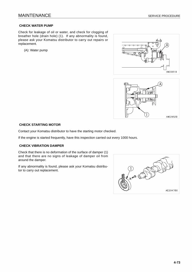
MAINTENANCE SERVICE PROCEDURE
CHECK WATER PUMP
Check for leakage of oil or water, and check for clogging ofbreather hole (drain hole) (1). If any abnormality is found,please ask your Komatsu distributor to carry out repairs orreplacement.
(A): Water pump
CHECK STARTING MOTOR
Contact your Komatsu distributor to have the starting motor checked.
If the engine is started frequently, have this inspection carried out every 1000 hours.
CHECK VIBRATION DAMPER
Check that there is no deformation of the surface of damper (1)and that there are no signs of leakage of damper oil fromaround the damper.
If any abnormality is found, please ask your Komatsu distribu-tor to carry out replacement.
4-73
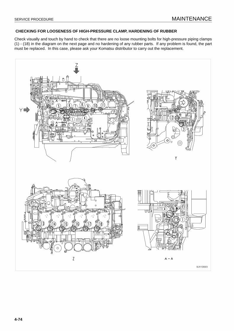
SERVICE PROCEDURE MAINTENANCE
CHECKING FOR LOOSENESS OF HIGH-PRESSURE CLAMP, HARDENING OF RUBBER
Check visually and touch by hand to check that there are no loose mounting bolts for high-pressure piping clamps(1) - (18) in the diagram on the next page and no hardening of any rubber parts. If any problem is found, the partmust be replaced. In this case, please ask your Komatsu distributor to carry out the replacement.
4-74
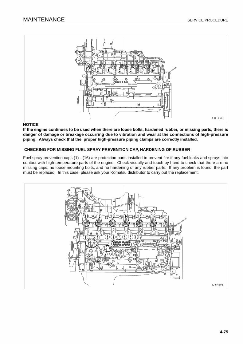
MAINTENANCE SERVICE PROCEDURE
NOTICEIf the engine continues to be used when there are loose bolts, hardened rubber, or missing parts, there isdanger of damage or breakage occurring due to vibration and wear at the connections of high-pressurepiping. Always check that the proper high-pressure piping clamps are correctly installed.
CHECKING FOR MISSING FUEL SPRAY PREVENTION CAP, HARDENING OF RUBBER
Fuel spray prevention caps (1) - (16) are protection parts installed to prevent fire if any fuel leaks and sprays intocontact with high-temperature parts of the engine. Check visually and touch by hand to check that there are nomissing caps, no loose mounting bolts, and no hardening of any rubber parts. If any problem is found, the partmust be replaced. In this case, please ask your Komatsu distributor to carry out the replacement.
4-75

SERVICE PROCEDURE MAINTENANCE
EVERY 8000 HOURS SERVICE 4
Maintenance for every 250, 500, 1000, 2000, and 4000 hours of service should be performed at the same time.
REPLACE HIGH-PRESSURE PIPING CLAMPS
Contact your Komatsu distributor to have the engine high-pressure clamps replaced.
REPLACE FUEL SPLAY PREVENTION CAPS
Contact your Komatsu distributor to have the fuel spray prevention cap replaced.
4-76

SPECIFICATIONS
15
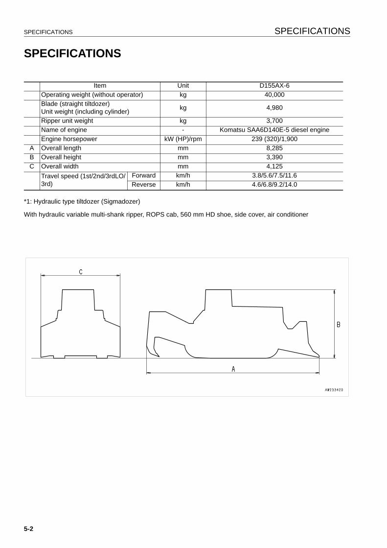
SPECIFICATIONS SPECIFICATIONS
SPECIFICATIONS 5
*1: Hydraulic type tiltdozer (Sigmadozer)
With hydraulic variable multi-shank ripper, ROPS cab, 560 mm HD shoe, side cover, air conditioner
Item Unit D155AX-6Operating weight (without operator) kg 40,000Blade (straight tiltdozer)Unit weight (including cylinder) kg 4,980
Ripper unit weight kg 3,700Name of engine - Komatsu SAA6D140E-5 diesel engineEngine horsepower kW (HP)/rpm 239 (320)/1,900
A Overall length mm 8,285B Overall height mm 3,390C Overall width mm 4,125
Travel speed (1st/2nd/3rdLO/3rd)
Forward km/h 3.8/5.6/7.5/11.6Reverse km/h 4.6/6.8/9.2/14.0
5-2

ATTACHMENTS, OPTIONS
16
WARNINGPlease read and make sure that you understand theSAFETYsection before reading this section.
GENERAL PRECAUTIONS ATTACHMENTS, OPTIONS
GENERAL PRECAUTIONS 6
PRECAUTIONS RELATED TO SAFETY 6
If attachments or options other than those authorized by Komatsu are installed, this will not only affect the life ofthe machine, but will also cause problems with safety.
When installing attachments not listed in this Operation and Maintenance Manual, contact your Komatsu distribu-tor first.
If you do not contact Komatsu, we cannot accept any responsibility for any accidents or failures.
WARNINGGeneral precautionsRead the instruction manual for the attachment thoroughly, and do not use this attachment unless you aresure that you have understood the guides completely.If you lose the instruction manual, always ask the manufacturer or your Komatsu distributor for a newcopy.Depending on the attachment, install the necessary front guard on the machine.Depending on the attachment, the impact noise may make it difficult for fellow workers to transmit instruc-tions for the operation. Before starting operation, decide a leader and determine the signals to be used.Do not carry out swinging operations to the side with a heavy load on the attachment. This is particularlydangerous on slopes.Comparing with a machine equipped with a bucket, a machine equipped with a breaker has a heavy load atthe front of the work equipment and is unstable. To avoid a hazard of tipping over, do not carry out opera-tions with the attachment swung to the side.When an attachment is installed, the swing range and center of gravity of the machine are different, andthe machine may move in an unexpected way. Be sure that you understand the condition of the machineproperly.Before starting operations, set up a fence around the machine to prevent people from entering.Never operate the machine when there are people near the machine.To prevent serious accidents caused by misoperation, do not put your foot on the pedal except whenoperating the pedal.
Precautions for removal and installation operationsWhen removing or installing the attachments, obey the following precautions and take care to ensuresafety during the operation.Carry out the removal and installation operation on a flat, firm ground surface.When the operation is carried out by two or more workers, determine the signals and follow these duringthe operation.When carrying heavy objects (more than 25 kg), use a crane.When removing heavy parts, always support the part before removing it.When lifting such as heavy parts with a crane, always pay careful attention to the position of the center ofgravity.It is dangerous to carry out operations with the load kept suspended. Always set the load on a stand, andcheck that it is safe.When removing or installing attachments, make sure that it is in a stable condition and will not fall over.Never go under a load suspended from a crane.Always stand in a position that is safe even if the load should fall.
NOTICEQualifications are required to operate a crane. Never allow the crane to be operated by an unqualified per-son.For details of removal and installation operations, contact your Komatsu distributor.
6-2

ATTACHMENTS, OPTIONS INTRODUCTION OF ATTACHMENTS AND OPTIONS
INTRODUCTION OF ATTACHMENTS AND OPTIONS 6
INTRODUCTION OF ATTACHMENTS AND OPTIONS 6
Various other optional parts are available, so please contact your Komatsu distributor.
Name Specifications, use
Track shoes
Wide shoe width 610 mm Wide shoe width 660 mm Wide shoe width 710 mm Heavy-duty shoe width 610 mm Heavy-duty shoe width 660 mm
Ripper pointCap with lockHeadrest
6-3

HEADREST, HANDLING ATTACHMENTS, OPTIONS
HEADREST, HANDLING 6
Use the headrest fully pushed in to the lowest position.
6-4
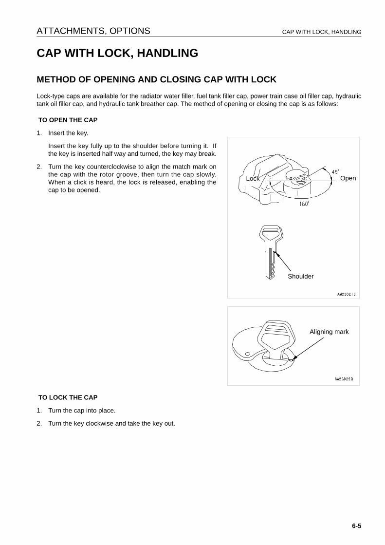
ATTACHMENTS, OPTIONS CAP WITH LOCK, HANDLING
CAP WITH LOCK, HANDLING 6
METHOD OF OPENING AND CLOSING CAP WITH LOCK 6
Lock-type caps are available for the radiator water filler, fuel tank filler cap, power train case oil filler cap, hydraulictank oil filler cap, and hydraulic tank breather cap. The method of opening or closing the cap is as follows:
TO OPEN THE CAP
1. Insert the key.
Insert the key fully up to the shoulder before turning it. Ifthe key is inserted half way and turned, the key may break.
2. Turn the key counterclockwise to align the match mark onthe cap with the rotor groove, then turn the cap slowly.When a click is heard, the lock is released, enabling thecap to be opened.
TO LOCK THE CAP
1. Turn the cap into place.
2. Turn the key clockwise and take the key out.
OpenLock
Shoulder
Aligning mark
6-5
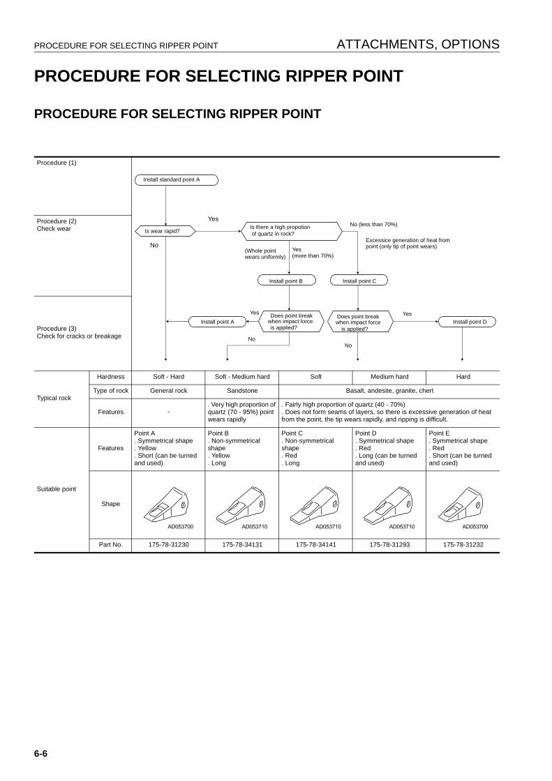
PROCEDURE FOR SELECTING RIPPER POINT ATTACHMENTS, OPTIONS
PROCEDURE FOR SELECTING RIPPER POINT 6
PROCEDURE FOR SELECTING RIPPER POINT 6
Procedure (1)
Procedure (2)Check wear
Procedure (3)Check for cracks or breakage
Typical rock
Hardness Soft - Hard Soft - Medium hard Soft Medium hard Hard
Type of rock General rock Sandstone Basalt, andesite, granite, chert
Features -. Very high proportion of quartz (70 - 95%) point wears rapidly
. Fairly high proportion of quartz (40 - 70%)
. Does not form seams of layers, so there is excessive generation of heat from the point, the tip wears rapidly, and ripping is difficult.
Suitable point
Features
Point A. Symmetrical shape. Yellow. Short (can be turned and used)
Point B. Non-symmetrical shape. Yellow. Long
Point C. Non-symmetrical shape. Red. Long
Point D. Symmetrical shape. Red. Long (can be turned and used)
Point E. Symmetrical shape. Red. Short (can be turned and used)
Shape
Part No. 175-78-31230 175-78-34131 175-78-34141 175-78-31293 175-78-31232
Install standard point A
Is wear rapid?
Yes
No
Is there a high propotion of quartz in rock?
No (less than 70%)
(Whole point wears uniformly)
Yes (more than 70%)
Install point B Install point C
Install point AYes Does point break
when impact force is applied?
Does point break when impact force
is applied?
YesInstall point D
NoNo
Excessice generation of heat frompoint (only tip of point wears)
6-6
ATTACHMENTS, OPTIONS HANDLING MACHINES EQUIPPED WITH KOMTRAX
HANDLING MACHINES EQUIPPED WITH KOMTRAX 6
q KOMTRAX is a machine management system that uses wireless communications.
q A contract with your Komatsu distributor is necessary before the KOMTRAX system can be used. Any cus-tomers desiring to use the KOMTRAX system should consult their Komatsu distributor.
q The KOMTRAX equipment is a wireless device using radio waves, so it is necessary to obtain authorizationand conform to the laws of the country or territory where the machine equipped with KOMTRAX is being used.Always contact your Komatsu distributor before selling or exporting any machine equipped with KOMTRAX.
q When selling or exporting the machine or at other times when your Komatsu distributor considers it necessary,it may be necessary for your Komatsu distributor to remove the KOMTRAX equipment or to carry out action tostop communications.
q If you do not obey the above precautions, neither Komatsu nor your Komatsu distributor can take any respon-sibility for any problem that is caused or for any loss that results.
BASIC PRECAUTIONS 6
WARNINGq Never disassemble, repair, modify, or move the communications terminal, antenna, or cables. This
may cause failure or fire on the KOMTRAX equipment or the machine itself. (Your Komatsu distributorwill carry out removal and installation of KOMTRAX.)
q Do not allow cables or cords to become caught; do not damage or pull cables or cords by force. Shortcircuits or disconnected wires may cause failure or fire on the KOMTRAX equipment or the machineitself.
q For anyone wearing a pacemaker, make sure that the communications antenna is at least 22 cm (8.7in) from the pacemaker. The radio waves may have an adverse effect on the operation of the pace-maker.
NOTICEq Even when the key in the starting switch of the KOMTRAX system is at the OFF position, a small
amount of electric power is consumed. When putting the machine into long-term storage, take the action given in “LONG-TERM STORAGE (3-150)“.
q Please contact your Komatsu distributor before installing a top guard or other attachment that covers the cab roof.
q Be careful not to get water on the communications terminal or wiring.
REMARKThe KOMTRAX system uses wireless communications, so it cannot be used inside tunnels, underground, insidebuildings, or in mountain areas where radio waves cannot be received. Even when the machine is outside, it can-not be used in areas where the radio signal is weak or in areas outside the wireless communication service area.There is absolutely no need to inspect or operate the KOMTRAX communications terminal, but if any abnormalityis found, please consult your Komatsu distributor.
6-7

HANDLING MACHINES EQUIPPED WITH KOMTRAX ATTACHMENTS, OPTIONS
6-8

INDEX
17

INDEX
7-2
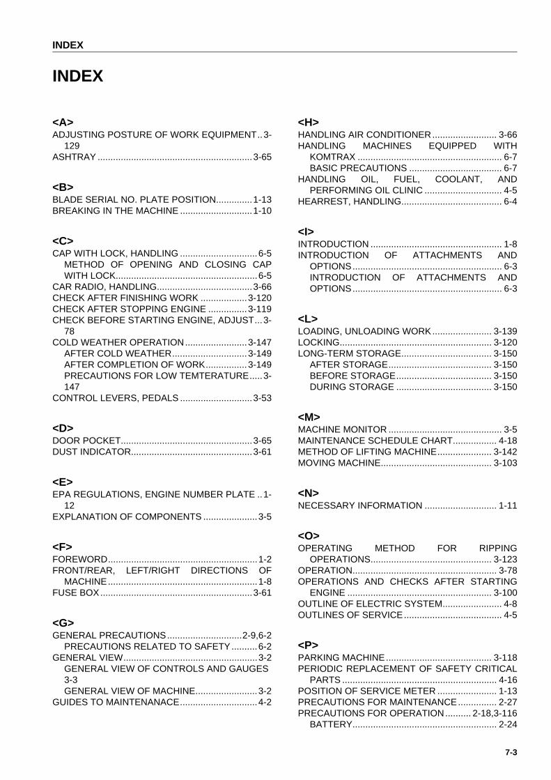
INDEX
INDEX1
<A>ADJUSTING POSTURE OF WORK EQUIPMENT..3-
129ASHTRAY ............................................................3-65
<B>BLADE SERIAL NO. PLATE POSITION..............1-13BREAKING IN THE MACHINE ............................1-10
<C>CAP WITH LOCK, HANDLING ..............................6-5
METHOD OF OPENING AND CLOSING CAPWITH LOCK.......................................................6-5
CAR RADIO, HANDLING.....................................3-66CHECK AFTER FINISHING WORK ..................3-120CHECK AFTER STOPPING ENGINE ...............3-119CHECK BEFORE STARTING ENGINE, ADJUST...3-
78COLD WEATHER OPERATION........................3-147
AFTER COLD WEATHER.............................3-149AFTER COMPLETION OF WORK................3-149PRECAUTIONS FOR LOW TEMTERATURE.....3-147
CONTROL LEVERS, PEDALS ............................3-53
<D>DOOR POCKET...................................................3-65DUST INDICATOR...............................................3-61
<E>EPA REGULATIONS, ENGINE NUMBER PLATE ..1-
12EXPLANATION OF COMPONENTS .....................3-5
<F>FOREWORD..........................................................1-2FRONT/REAR, LEFT/RIGHT DIRECTIONS OF
MACHINE..........................................................1-8FUSE BOX...........................................................3-61
<G>GENERAL PRECAUTIONS.............................2-9,6-2
PRECAUTIONS RELATED TO SAFETY..........6-2GENERAL VIEW....................................................3-2
GENERAL VIEW OF CONTROLS AND GAUGES3-3GENERAL VIEW OF MACHINE........................3-2
GUIDES TO MAINTENANACE..............................4-2
<H>HANDLING AIR CONDITIONER......................... 3-66HANDLING MACHINES EQUIPPED WITH
KOMTRAX ........................................................ 6-7BASIC PRECAUTIONS .................................... 6-7
HANDLING OIL, FUEL, COOLANT, ANDPERFORMING OIL CLINIC .............................. 4-5
HEARREST, HANDLING....................................... 6-4
<I>INTRODUCTION ................................................... 1-8INTRODUCTION OF ATTACHMENTS AND
OPTIONS.......................................................... 6-3INTRODUCTION OF ATTACHMENTS ANDOPTIONS.......................................................... 6-3
<L>LOADING, UNLOADING WORK....................... 3-139LOCKING........................................................... 3-120LONG-TERM STORAGE................................... 3-150
AFTER STORAGE........................................ 3-150BEFORE STORAGE..................................... 3-150DURING STORAGE ..................................... 3-150
<M>MACHINE MONITOR ............................................ 3-5MAINTENANCE SCHEDULE CHART................. 4-18METHOD OF LIFTING MACHINE..................... 3-142MOVING MACHINE........................................... 3-103
<N>NECESSARY INFORMATION ............................ 1-11
<O>OPERATING METHOD FOR RIPPING
OPERATIONS............................................... 3-123OPERATION........................................................ 3-78OPERATIONS AND CHECKS AFTER STARTING
ENGINE ........................................................ 3-100OUTLINE OF ELECTRIC SYSTEM....................... 4-8OUTLINES OF SERVICE...................................... 4-5
<P>PARKING MACHINE......................................... 3-118PERIODIC REPLACEMENT OF SAFETY CRITICAL
PARTS ............................................................ 4-16POSITION OF SERVICE METER ....................... 1-13PRECAUTIONS FOR MAINTENANCE............... 2-27PRECAUTIONS FOR OPERATION.......... 2-18,3-116
BATTERY........................................................ 2-24
7-3

INDEX
BEFORE STARTING ENGINE........................2-18OPERATION ...................................................2-19TOWING..........................................................2-26TRANSPORTATION .......................................2-23
PRECAUTIONS FOR TRANSPORTATION ......3-144PROCEDURE FOR SELECTING RIPPER POINT 6-6
PROCEDURE FOR SELECTING RIPPER POINT6-6
PRODUCT IDENTIFICATION NUMBER (PIN),MACHINE SERIAL NO. PLATE ......................1-11
<R>RECOMMENDED FUEL, COOLANT, AND
LUBRICANT ....................................................4-12RECOMMENDED BRANDS, RECOMMENDEDQUALITY FOR PRODUCTS OTHER THANKOMATSU GENUINE OIL...............................4-14
REMOVAL OF CAB ...........................................3-145RIPPER OPERATION........................................3-120RIPPER SERIAL NO. PLATE POSITION ............1-13ROPS, FOPS NO. PLATE POSITION .................1-13
<S>SAFETY .................................................................2-2SAFETY CRITICAL PARTS.................................4-16SAFETY INFORMATION .......................................1-3SAFETY LABELS...................................................2-4
POSITIONS OF SAFETY PICTOGRAMS.........2-4SAFETY LABELS ..............................................2-5
SERVICE PROCEDURE .....................................4-20CHECK BEFORE STARTING .........................4-39EVERY 1000 HOURS SERVICE.....................4-55EVERY 2000 HOURS SERVICE.....................4-65EVERY 250 HOURS SERVICE.......................4-40EVERY 4000 HOURS SERVICE.....................4-72EVERY 500 HOURS SERVICE.......................4-48EVERY 8000 HOURS SERVICE.....................4-76INITIAL 250 HOURS SERVICE (ONLY AFTERTHE FIRST 250 HOURS)................................4-20WHEN REQUIRED..........................................4-20
SHIFTING BETWEEN FORWARD AND REVERSE3-112
SHIFTING GEAR ...............................................3-106SPECIFICATIONS .................................................5-2STANDARD TIGHTENING TORQUES FOR BOLTS
AND NUTS ......................................................4-15STARTING NEGINE ............................................3-95STEERING MACHINE .......................................3-114STOPPING ENGINE..........................................3-102STOPPING MACHINE .......................................3-105SWITCHES ..........................................................3-49
<T>TABLE TO ENTER SERIAL NO. AND DISTRIBUTOR
1-14TIPS FOR LOMGER UNDERCARRIAGE LIFE.3-136TORQUE LIST .....................................................4-15
TRANSPORTATION.......................................... 3-139TRAVELING ON ROADS .................................. 3-144TROUBLESHOOTING....................................... 3-151
AFTER RUNNING OUT OF FUEL................ 3-151IF BATTERY IS DISCHARGED .................... 3-154METHOD OF TOWING MACHINE ............... 3-153OTHER TROUBLE........................................ 3-158
<V>VISIBILITY FROM OPERATORSSEAT'................ 1-9
<W>WEAR PARTS LIST ............................................ 4-10WORK POSSIBLE USING BULLDOZER.......... 3-127
7-4

COLOPHON
18

COLOPHON
D155AX-6 GALEO BULLDOZER
Form No. EEAM025000
© 2006 KOMATSUAll Rights ReservedPrinted in Belgium 02-06
8-2


![Operacion y Mantencion D155AX-5[1]](https://img.pdfslide.net/doc/110x75/577cdc2d1a28ab9e78aa1257/operacion-y-mantencion-d155ax-51.jpg)