Embed Size (px)
Citation preview
D2.1 – Use Case Scenarios, and Technical System
Requirements Definition – ver. 1.1
Document Number D2.1
Status Issue 1.1
Work Package WP 2.1
Deliverable Type Report
Date of Delivery 2/January/2017
Responsible KDDI
Contributors AALTO, Ericsson, Orange, FOKUS, EI, MI, DG,
EURECOM, UT, KDDI, HITACHI, WU, NESIC
Dissemination level PU
D2.1 – Use case scenarios, and technical system requirements definition
5G!Pagoda Version 1.1 Page 2 of 106
AUTHORS
Full Name Affiliation
Yoshinori Kitatsuji KDDI Research
Zaw Htike KDDI Research
Itsuro Morita KDDI Research
Yoshiaki Kiriha University of Tokyo
Akihiro Nakao University of Tokyo
Du Ping University of Tokyo
Shu Yamamoto University of Tokyo
Daisuke Okabe Hitachi
Hidenori Inouchi Hitachi
Toshiaki Suzuki Hitachi
Toshitaka Tsuda Waseda University
Masato Yamazaki NESIC
Hiroshi Takezawa NESIC
Daisuke Nakagawa NESIC
Xu Chao NESIC
Tarik Taleb Aalto University
Miloud Bagaa Aalto University
Ibrahim Afolabi Aalto University
Slawomir Kuklinski ORANGE
Le Wang ERICSSON
Eunah Kim Device Gateway
Corici, Marius-Iulian Fraunhofer FOKUS
Adlen Ksentini EURECOM
Change History
Version Date Status Author (Company) Description
1.0 30 Nov.2016 Issue 1.0 All partners First approved version
1.1 2 Jan. 2017 Issue 1.1 Akihiro Nakao (UT), Tarik Taleb (AALTO)
Added: pg. 2. Authors: Le Wang, Ericsson; pg. 56. Footnote in 5.1.1
D2.1 – Use case scenarios, and technical system requirements definition
5G!Pagoda Version 1.1 Page 3 of 106
Executive Summary
This deliverable provides the basis for the work of all the WPs of the 5G!Pagoda project, which aims to
align Europe and Japan views on 5G Mobile network infrastructure; featuring Dynamic Creation and
Management of Network Slices for Different Mobile Services. The current document reflects the identified
reference scenarios, use cases, technical system requirements and overall architecture guidelines for
5G!Pagoda.
The document begins by reviewing and analysing the use cases discussed in the main representative 5G
SDOs and fora such as 3GPP, NGMN, and 5GMF, and active research projects such as 5GPPP Phase 1
projects. Then, eight use-cases, i.e., Smart Drive-Assistant Services, Industrial Factory Management,
Ensuring QoS On Demand, Smart/Virtual Office, Contents Delivery Network as a Service, Advancement of
Medical Services, Massive IoT, Disaster handling, have been carefully selected according to criteria,
relevant to the 5G!Pagoda context. To be more precise, we select use cases such that:
they should be supported by the current 4G technology,
they can be supported in a much more effective way using the 5G technology,
they have a great potential for future local/international mobile markets,
they can create new business model/opportunities for various business region operators,
they have a great value from societal viewpoints, and
they have high relevance to Tokyo Olympics.
Each use-case has been analysed and detailed by indicating: (i) the involved and the role of stakeholders;
(ii) anticipated capabilities and requirements to support the use-case. Resulting from the analysis, we
refined and regrouped the eight use-cases into three reference scenarios, aiming at covering all the vital
capabilities identified in the selected eight use cases. The major design point of the reference scenarios is
to get clear benefits from the multi-slice systems that 5G!Pagoda aims for.
Having in mind the three reference scenarios requirements, we devised the high level architecture of
5G!Pagoda. The envisioned architecture contains the functional blocks and interfaces to facilitate the
creation, deployment and management of Network Slices over single domain and multi-domain. Whilst the
proposed architecture is designed to be closely compatible with the ETSI NFV architecture, it has innovative
extension to enable new functional blocks and interfaces to meet multi-domain resource deployment and
orchestration.
The outcomes of this document will guide the future work in 5G!Pagoda as follows:
Task 2.3 in the project plans to elaborate the interfaces and functional blocks of the introduced
high level 5G!Pagoda architecture.
Other work packages will devise, develop and implement the different algorithms and mechanisms
required by the functional blocks, e.g., orchestration, management, resource placement, etc.
The detailed description of the three reference scenarios will be used to validate the proposed
5G!Pagoda architecture.
D2.1 – Use case scenarios, and technical system requirements definition
5G!Pagoda Version 1.1 Page 4 of 106
Table of Contents
1. Introduction ....................................................................................................................... 12
1.1. Objectives .....................................................................................................................................12
1.2. Motivation and Scope ..................................................................................................................12
1.3. Relationships with other Tasks in WP2 and other WPs ...............................................................13
1.4. Structure of the document...........................................................................................................13
2. Terminology ....................................................................................................................... 15
3. Reference Scenario and System Capability .......................................................................... 18
3.1. Analysis of Use Cases defined by SDOs and research projects ....................................................18
3.1.1. 3GPP and NGMN ..................................................................................................................18
3.1.2. 5GPPP ...................................................................................................................................19
3.1.3. METIS-II ................................................................................................................................20
3.1.4. 5GMF ...................................................................................................................................20
3.2. 5G!Pagoda use cases in vertical business areas ...........................................................................25
3.2.1. Use case 1: Smart Drive-Assistant Services .........................................................................26
3.2.2. Use case 2: Industrial Factory Management .......................................................................26
3.2.3. Use case 3: Ensuring QoS On Demand .................................................................................27
3.2.4. Use case 4: Smart/Virtual Office ..........................................................................................27
3.2.5. Use case 5: Contents Delivery Network as a Service ...........................................................28
3.2.6. Use case 6: Advancement of Medical Services ....................................................................29
3.2.7. Use case 7: Massive IoT .......................................................................................................30
3.2.8. Use case 8: Disaster handling ..............................................................................................30
3.3. Stakeholders .................................................................................................................................31
3.3.1. Use case 1: Smart Drive-Assistant Services .........................................................................31
3.3.2. Use case 2: Industrial Factory Management .......................................................................32
3.3.3. Use case 3: Ensuring QoS on demand..................................................................................33
3.3.4. Use case 4: Smart/Virtual Offices ........................................................................................34
3.3.5. Use case 5: Content Delivery Network as a Service .............................................................35
3.3.6. Use case 6: Advancement of Medical Services ....................................................................36
3.3.7. Use case 7: Massive IoT .......................................................................................................37
3.3.8. Use case 8: Disaster handling ..............................................................................................37
3.3.9. Stakeholder Classification ....................................................................................................38
3.4. Capabilities Expected in 5G System .............................................................................................41
D2.1 – Use case scenarios, and technical system requirements definition
5G!Pagoda Version 1.1 Page 5 of 106
3.4.1. Use case 1: Smart Drive-Assistant Services .........................................................................41
3.4.2. Use case 2: Industrial Factory Management .......................................................................41
3.4.3. Use case 3: Ensuring QoS on demands ................................................................................42
3.4.4. Use case 4: Smart/Virtual Offices ........................................................................................42
3.4.5. Use case 5: Content Delivery Network as a Service .............................................................43
3.4.6. Use case 6: Advancement of Medical Services ....................................................................44
3.4.7. Use case 7: Massive IoT .......................................................................................................44
3.4.8. Use case 8: Disaster handling ..............................................................................................45
3.4.9. Summary of Anticipated Capability .....................................................................................45
3.5. Reference Use Case Scenarios .....................................................................................................46
3.5.1. Reference 1: Reference Use Case Scenario of Remote Monitoring in Industrial Domain (use
cases 2, 7, and 8) ..................................................................................................................................47
3.5.2. Reference 2: Reference Use Case Scenario of Tourism Support (use cases 3 and 5) ..........48
3.5.3. Reference 3: Reference Use Case Scenario of Office Roaming (use cases 3,4 and 5) ........48
4. Analysis of Reference Scenarios and Technical Requirements .............................................. 51
4.1. Capabilities difficult to provide/realize to all the users ...............................................................51
4.2. Capability on Demand (Service Provisioning Dynamics) ..............................................................52
4.3. Service Provisioning in Race Condition ........................................................................................53
4.4. Interwork among Service Providers and among Stakeholders ....................................................54
5. 5G!Pagoda Architecture Model and Concepts ...................................................................... 56
5.1. General Concepts .........................................................................................................................56
5.1.1. Mobile Network Slicing[34]....................................................................................................56
5.1.2. Slice High-Level Architecture Templates .............................................................................57
5.1.3. Life-Cycle Orchestration ......................................................................................................58
5.1.4. Multi-Domain Slicing System ...............................................................................................59
5.1.5. Dynamic Adaptation Stack ...................................................................................................62
5.2. Architecture Reference Model .....................................................................................................64
5.2.1. Orchestration Architecture ..................................................................................................64
5.2.2. Slice Architecture .................................................................................................................67
5.3. Slice Life-Cycle Management .......................................................................................................71
5.4. Architecture Reference Points and Protocol ................................................................................73
6. Concluding Remarks ........................................................................................................... 74
Appendix A. 5G System Use Cases and Requirements summary analysed by 3GPP and NGMN
75
D2.1 – Use case scenarios, and technical system requirements definition
5G!Pagoda Version 1.1 Page 6 of 106
Appendix B. Use Case Scenario analysed by 5GMF ................................................................ 92
B.1 User case scenarios on entertainments .............................................................................................92
B.2 User case scenarios on transportations .............................................................................................98
B.3 User case scenarios on industries and verticals ...............................................................................100
B.4 User case scenarios on emergency and disaster relief .....................................................................102
D2.1 – Use case scenarios, and technical system requirements definition
5G!Pagoda Version 1.1 Page 7 of 106
List of Tables
Table 1 – List of Acronyms ....................................................................................................................10
Table 2 – Terms defined in this document ...........................................................................................15
Table 3 - Expected features of use case scenarios #1-6 (Appendix B) ..................................................21
Table 4 – Expected features of use case scenarios #7 and 8 (Appendix B) ..........................................22
Table 5 – Expected features of use case scenarios #9 and 10 (Appendix B) ........................................23
Table 6 – Expected features of use case scenarios #11-13 (Appendix B) .............................................24
Table 7 – Scenario combinations in terms of anticipated features in 5G system.................................24
Table 8 – Stakeholder classifications ...................................................................................................38
Table 9 – Capability set for each 5G!Pagoda use case scenarios ..........................................................45
Table 10 - 3GPP and NGMN: 5G Use cases and requirements summary .............................................75
D2.1 – Use case scenarios, and technical system requirements definition
5G!Pagoda Version 1.1 Page 8 of 106
List of Figures
Figure 1 – Use-cases family and category per 3GPP and NGMN ..........................................................19
Figure 2 – METIS-II categorization of 5G mobile services .....................................................................20
Figure 3 – Usage scenarios on entertainments ....................................................................................21
Figure 4 – Usage scenarios on transportations .....................................................................................22
Figure 5 – Usage scenarios on industry and verticals ...........................................................................23
Figure 6 – Usage scenarios on emergency and disaster relief ..............................................................23
Figure 7 – Examples of a required feature set (separated view) ..........................................................25
Figure 8 – Examples of a required feature set (merged view) ..............................................................25
Figure 9 – CDNaaS platform high level diagram. ..................................................................................29
Figure 10 – Relationship among stakeholders and provided values for Smart Drive-Assistant Services
......................................................................................................................................................32
Figure 11 – Relationship between stakeholders and provided values for industrial factory management
......................................................................................................................................................33
Figure 12 – Relationship between stakeholders and provided values for ensuring QoS on demand ..34
Figure 13 – Relationship among stakeholders and provided values for Smart/Virtual Offices ...........35
Figure 14 – Relationship between stakeholders and provided values for Content Delivery Network as
a Service ........................................................................................................................................36
Figure 15 – Relationship between stakeholders and provided values for Advancement of Medical
Treatments ....................................................................................................................................37
Figure 16 – Relationship between classified stakeholders, and provided values .................................40
Figure 17 – Slice high-level architecture Templates .............................................................................57
Figure 18 – Instantiated 5G slices on top of the same infrastructure ..................................................58
Figure 19 – Life-cycle orchestration for multi-domain architecture .....................................................60
Figure 20 – Recursive resource orchestration ......................................................................................61
Figure 21 – Dynamic adaptation stack ..................................................................................................63
Figure 22 – Orchestration architecture ................................................................................................65
Figure 23 – Slice high-level architecture ...............................................................................................68
Figure 24 - Single domain slice creation via direct interaction with “domain specific slice orchestrator”
......................................................................................................................................................71
Figure 25 - Single domain slice creation via direct interaction with “multi-domain slice orchestrator”
......................................................................................................................................................72
Figure 26 - Multi-domain slice creation via direct interaction with “multi-domain slice orchestrator”
......................................................................................................................................................72
D2.1 – Use case scenarios, and technical system requirements definition
5G!Pagoda Version 1.1 Page 9 of 106
Figure 27 - Multi-domain slice creation via direct interaction with “domain specific slice orchestrator”
......................................................................................................................................................73
D2.1 – Use case scenarios, and technical system requirements definition
5G!Pagoda Version 1.1 Page 10 of 106
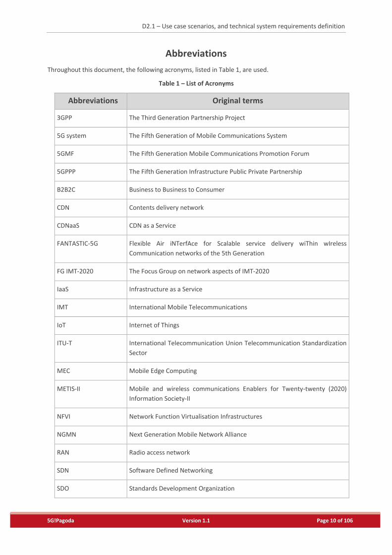
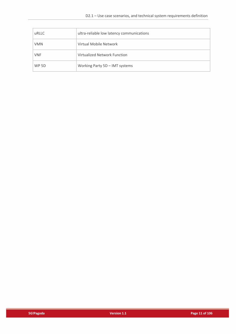
Abbreviations
Throughout this document, the following acronyms, listed in Table 1, are used.
Table 1 – List of Acronyms
Abbreviations Original terms
3GPP The Third Generation Partnership Project
5G system The Fifth Generation of Mobile Communications System
5GMF The Fifth Generation Mobile Communications Promotion Forum
5GPPP The Fifth Generation Infrastructure Public Private Partnership
B2B2C Business to Business to Consumer
CDN Contents delivery network
CDNaaS CDN as a Service
FANTASTIC-5G Flexible Air iNTerfAce for Scalable service delivery wiThin wIreless
Communication networks of the 5th Generation
FG IMT-2020 The Focus Group on network aspects of IMT-2020
IaaS Infrastructure as a Service
IMT International Mobile Telecommunications
IoT Internet of Things
ITU-T International Telecommunication Union Telecommunication Standardization
Sector
MEC Mobile Edge Computing
METIS-II Mobile and wireless communications Enablers for Twenty-twenty (2020)
Information Society-II
NFVI Network Function Virtualisation Infrastructures
NGMN Next Generation Mobile Network Alliance
RAN Radio access network
SDN Software Defined Networking
SDO Standards Development Organization
D2.1 – Use case scenarios, and technical system requirements definition
5G!Pagoda Version 1.1 Page 11 of 106
uRLLC ultra-reliable low latency communications
VMN Virtual Mobile Network
VNF Virtualized Network Function
WP 5D Working Party 5D – IMT systems
D2.1 – Use case scenarios, and technical system requirements definition
5G!Pagoda Version 1.1 Page 12 of 106
1. Introduction
1.1. Objectives
The objectives of Work Package 2 (WP2) is to define a set of reference use case scenarios for 5G!Pagoda
with identification of their technical requirements (Task 2.1), to define target business models for the
5G!Pagoda ecosystem (Task 2.2) and to define 5G!Padoga architecture with description of the
specifications of different slices for different verticals (Task 2.3).
The objective of this Deliverable D2.1 is to identify use cases from the several business verticals with related
stakeholders and to define reference scenarios that fulfil the objective of the 5G!Pagoda. This deliverable
also identifies technical system requirements of the identified use cases and provides high-level
architecture guidelines for 5G!Pagoda.
1.2. Motivation and Scope
In the recent years, there have been noticeable research initiatives on the fifth Generation of Mobile
Communications System (5G System), in Europe, Japan, and around the Globe. However, the focus has
been merely on high-level concepts and technology components. A comprehensive and detailed 5G
architecture is yet to be defined; leaving still space for research and standards activities to shape the 5G
system architecture, which defines one of the core objectives of this 5G!Pagoda project.
It is generally agreed that cloud computing, Software Defined Networking (SDN), and Network Function
Virtualisation (NFV) will be key enabling technologies for 5G mobile system. For example, ITU-T FG IMT-
2020 identifies “network softwarization” as one of the most crucial technology focus areas for defining 5G
mobile networks. According to ITU-T, network softwarization is an overall transformation trend for
designing, implementing, deploying, managing and maintaining network equipment and network
components by software programming, exploiting characteristics of software such as flexibility and rapidity
of design, development and deployment throughout the lifecycle of network equipment and components,
for creating conditions that enable the re-design of network and services architectures; allow optimization
of costs and processes; and enable self-management[1].
Indeed, an efficient integration of such software-based technologies (e.g., SDN and NFV) with cloud
computing ensures several advantages in terms of network configuration flexibility, scalability, and
elasticity, which are highly needed to fulfil the numerous requirements of 5G system. Furthermore,
network management procedures of 5G system should be as simple as possible; allowing network
operators to orchestrate their Network Function Virtualisation Infrastructures (NFVIs) and to automatically
manage the lifecycle of the supported Virtual Mobile Networks (VMNs) and the corresponding Virtualized
Network Functions (VNFs).
With the current mobile network designs, such required flexibility and elasticity are all but impossible to
realize particularly due to the traditional usage of specific-purpose networking equipment that can neither
dynamically scale with mobile traffic nor be easily upgraded with new functions. Furthermore, 5G system
is envisioned to accommodate not only smartphones and tablets, but also cars, drones, industrial machines
and sensors.
Mobile networks are nowadays architected to serve all mobile users and all service types, ensuring some
degree of service-level differentiation but not specifically tailored to the individual needs of users and their
D2.1 – Use case scenarios, and technical system requirements definition
5G!Pagoda Version 1.1 Page 13 of 106
equipment types or to the specific requirements of mobile services. On the other hand, users exhibit
significant diversity in their usage habits[2][3]. Mobile services also exhibit diverse requirements in terms of
user data rate, latency, jitter, reliability, and mobility support. From these observations, it becomes
apparent that we must rethink having the same mobile network architecture serving all mobile users, all
user equipment types, and all mobile service types, despite the diverse requirements of mobile services
and the various responses of users to mobile services.
To cope with this, 5G!Pagoda aims for taking the concept of mobile networking a major leap forward,
whereby slices of virtual mobile networks are created on-demand and customized according to the
changing needs of mobile services.
As the 5G!Pagoda project aims to provide scenario-driven and vertical-centric technologies, significant
efforts have been made in the beginning of the project to derive various types of reference scenarios and
use cases. There are several use cases defined by SDOs and diverse research projects. We have analysed
the well-indicated 5G use cases from the previous studies and carefully selected 5G!Padoda use cases
based on the use cases. Each scenario is based on a sound technical case, as opposed to just selecting
hypothetical scenarios to be implemented. The selected scenarios have been derived in a way to highlight
and demonstrate the technical innovations in 5G!Pagoda. The analysis and the selected use cases are
detailed in the Section 3. For each use cases, we have identified and evaluated the key stakeholders and
technical service requirements (both of functional and non-functional) in the Sections 3 and 4. Based on
the study results of the use cases and the corresponding technical requirements, high-level concept and
description of the reference architecture model are provided in Section 5 of this document.
1.3. Relationships with other Tasks in WP2 and other WPs
The identified stakeholders in each use cases will be used as inputs for Task 2.2 where business analysis
and models of 5G!Pagoda is handled. In the upcoming deliverable D2.2, the actors, roles, value chain
configurations and related business model, and market trends and issues will be identified for each
reference scenario.
The identified technical requirements together with the high-level description of the reference architecture
model will be used as inputs for the design of the 5G!Pagoda architecture in Task 2.3. The architecture will
be further detailed in the upcoming deliverable D2.3.
The identified reference scenarios will be used as inputs of WP5 where integrated testbed and validation
will be handled.
1.4. Structure of the document
Following this introductory section, the remaining part of the document is structured as follows:
Section 2 provides the basic terminology used throughout this report. It includes the descriptions of
abbreviations, and technical terms.
Section 3 describes the reference scenarios, stakeholders and system capabilities. From a broad
survey of the user cases in documents from Standard Development Organizations (SDOs) and research
projects, this section describes the relationship between the reference scenarios and stakeholders.
D2.1 – Use case scenarios, and technical system requirements definition
5G!Pagoda Version 1.1 Page 14 of 106
Section 4 analyses the reference scenarios and describes technical requirements to implement 5G
system, which are structured in four main technical domains. This section details the technical
requirements of the slice mechanisms and orchestration.
Section 5 describes the high level architecture of 5G!Pagoda and provides recommendations and
guidelines for slice mechanisms and the overall system orchestration. The 5G!Pagoda architecture will
be further detailed in the upcoming deliverable D2.3: “Initial report on the overall system architecture
definition”.
Section 6 draws important concluding remarks and future work.
In addition, complementary information is provided in two Appendices, including:
The detailed use cases from 3GPP and NGMN referenced to in Section 3.1.1 (Appendix A), and
The detailed use cases from 5GMF, referenced to in Section 3.1.4 (Appendix B).
D2.1 – Use case scenarios, and technical system requirements definition
5G!Pagoda Version 1.1 Page 15 of 106
2. Terminology
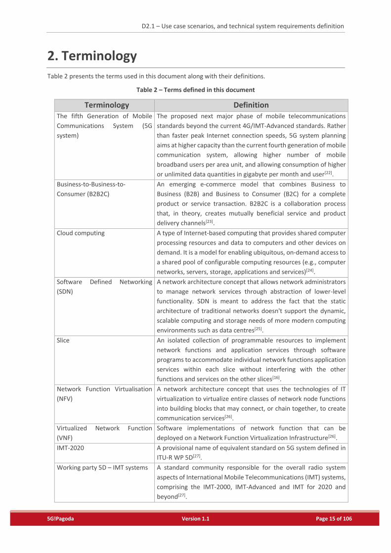
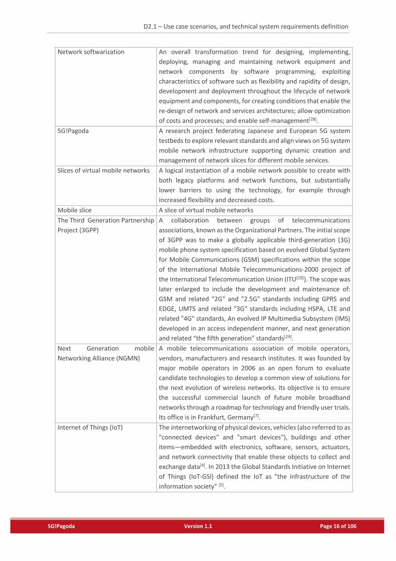
Table 2 presents the terms used in this document along with their definitions.
Table 2 – Terms defined in this document
Terminology Definition
The fifth Generation of Mobile
Communications System (5G
system)
The proposed next major phase of mobile telecommunications
standards beyond the current 4G/IMT-Advanced standards. Rather
than faster peak Internet connection speeds, 5G system planning
aims at higher capacity than the current fourth generation of mobile
communication system, allowing higher number of mobile
broadband users per area unit, and allowing consumption of higher
or unlimited data quantities in gigabyte per month and user[22].
Business-to-Business-to-
Consumer (B2B2C)
An emerging e-commerce model that combines Business to
Business (B2B) and Business to Consumer (B2C) for a complete
product or service transaction. B2B2C is a collaboration process
that, in theory, creates mutually beneficial service and product
delivery channels[23].
Cloud computing A type of Internet-based computing that provides shared computer
processing resources and data to computers and other devices on
demand. It is a model for enabling ubiquitous, on-demand access to
a shared pool of configurable computing resources (e.g., computer
networks, servers, storage, applications and services)[24].
Software Defined Networking
(SDN)
A network architecture concept that allows network administrators
to manage network services through abstraction of lower-level
functionality. SDN is meant to address the fact that the static
architecture of traditional networks doesn't support the dynamic,
scalable computing and storage needs of more modern computing
environments such as data centres[25].
Slice An isolated collection of programmable resources to implement
network functions and application services through software
programs to accommodate individual network functions application
services within each slice without interfering with the other
functions and services on the other slices[16].
Network Function Virtualisation
(NFV)
A network architecture concept that uses the technologies of IT
virtualization to virtualize entire classes of network node functions
into building blocks that may connect, or chain together, to create
communication services[26].
Virtualized Network Function
(VNF)
Software implementations of network function that can be
deployed on a Network Function Virtualization Infrastructure[26].
IMT-2020 A provisional name of equivalent standard on 5G system defined in
ITU-R WP 5D[27].
Working party 5D – IMT systems A standard community responsible for the overall radio system
aspects of International Mobile Telecommunications (IMT) systems,
comprising the IMT-2000, IMT-Advanced and IMT for 2020 and
beyond[27].
D2.1 – Use case scenarios, and technical system requirements definition
5G!Pagoda Version 1.1 Page 16 of 106
Network softwarization An overall transformation trend for designing, implementing,
deploying, managing and maintaining network equipment and
network components by software programming, exploiting
characteristics of software such as flexibility and rapidity of design,
development and deployment throughout the lifecycle of network
equipment and components, for creating conditions that enable the
re-design of network and services architectures; allow optimization
of costs and processes; and enable self-management[28].
5G!Pagoda A research project federating Japanese and European 5G system
testbeds to explore relevant standards and align views on 5G system
mobile network infrastructure supporting dynamic creation and
management of network slices for different mobile services.
Slices of virtual mobile networks A logical instantiation of a mobile network possible to create with
both legacy platforms and network functions, but substantially
lower barriers to using the technology, for example through
increased flexibility and decreased costs.
Mobile slice A slice of virtual mobile networks
The Third Generation Partnership
Project (3GPP)
A collaboration between groups of telecommunications
associations, known as the Organizational Partners. The initial scope
of 3GPP was to make a globally applicable third-generation (3G)
mobile phone system specification based on evolved Global System
for Mobile Communications (GSM) specifications within the scope
of the International Mobile Telecommunications-2000 project of
the International Telecommunication Union (ITU[19]). The scope was
later enlarged to include the development and maintenance of:
GSM and related "2G" and "2.5G" standards including GPRS and
EDGE, UMTS and related "3G" standards including HSPA, LTE and
related "4G" standards, An evolved IP Multimedia Subsystem (IMS)
developed in an access independent manner, and next generation
and related “the fifth generation” standards[29].
Next Generation mobile
Networking Alliance (NGMN)
A mobile telecommunications association of mobile operators,
vendors, manufacturers and research institutes. It was founded by
major mobile operators in 2006 as an open forum to evaluate
candidate technologies to develop a common view of solutions for
the next evolution of wireless networks. Its objective is to ensure
the successful commercial launch of future mobile broadband
networks through a roadmap for technology and friendly user trials.
Its office is in Frankfurt, Germany[7].
Internet of Things (IoT) The internetworking of physical devices, vehicles (also referred to as
"connected devices" and "smart devices"), buildings and other
items—embedded with electronics, software, sensors, actuators,
and network connectivity that enable these objects to collect and
exchange data[4]. In 2013 the Global Standards Initiative on Internet
of Things (IoT-GSI) defined the IoT as "the infrastructure of the
information society" [5].
D2.1 – Use case scenarios, and technical system requirements definition
5G!Pagoda Version 1.1 Page 17 of 106
The Fifth Generation
Infrastructure Public Private
Partnership
A group initiated by the European Commission and industry
manufacturers, telecommunications operators, service providers,
SMEs and researchers. It aims to deliver solutions, architectures,
technologies and standards for the ubiquitous next generation
communication infrastructures of the coming decade[12].
FANTASTIC-5G A research project funded by HORIZON2020 consisting of 16
telecom players that aim to develop a new air interface below 6 GHz
for 5G networks[9].
Mobile and wireless
communications Enablers for
Twenty-twenty (2020)
Information Society-II (METIS-II)
A research project aiming to develop the overall 5G radio access
network design and to provide the technical enablers needed for an
efficient integration and use of the various 5G technologies and
components currently developed. It provides the 5G collaboration
framework within 5GPPP for a common evaluation of 5G radio
access network concepts and prepare concerted action towards
regulatory and standardisation bodies[10].
The Fifth Generation Mobile
Communications Promotion
Forum (5GMF)
A group actively promoting 5G system study in line with trends both
in Japan and abroad based on a roadmap on 5G system
implementation policy published by the government of Japan[30].
Mobile Edge Computing (MEC) A network architecture concept that enables cloud computing
capabilities and an IT service environment at the edge of the cellular
network. The basic idea behind MEC is that by running applications
and performing related processing tasks closer to the cellular
customer, network congestion is reduced and applications perform
better[32][36-38].
Contents delivery network (CDN) A globally distributed network of proxy servers deployed in multiple
data centres. The goal of a CDN is to serve content to end-users with
high availability and high performance. CDNs serve a large fraction
of the Internet content today, including web objects (text, graphics
and scripts), downloadable objects (media files, software,
documents), applications (e-commerce, portals), live streaming
media, on-demand streaming media, and social networks[31][35].
Quality of Experience (QoE) A measure of a customer's experiences with a service (web
browsing, phone call, TV broadcast, call to a Call Centre). QoE
focuses on the entire service experience, and is a more holistic
evaluation than the more narrowly focused user experience
(focused on a software interface) and customer-support experience
(support focused)[33].
D2.1 – Use case scenarios, and technical system requirements definition
5G!Pagoda Version 1.1 Page 18 of 106
3. Reference Scenario and System Capability
3.1. Analysis of Use Cases defined by SDOs and research projects
One of the key targets of the upcoming 5G systems is to build a novel network architecture that shall
support not only classical mobile broadband applications and services, but also vertical industries (e.g.
automotive systems, smart grid, and public safety) and IoT-based services. Besides devices operated
by human (i.e. smart-phones and tablets), 5G systems will also include sensors, actuators and vehicles.
All these requirements have been driven by the envisioned 5G system use-cases. Indeed, several SDOs
and ongoing 5G research projects have defined different 5G system use-cases with different targets.
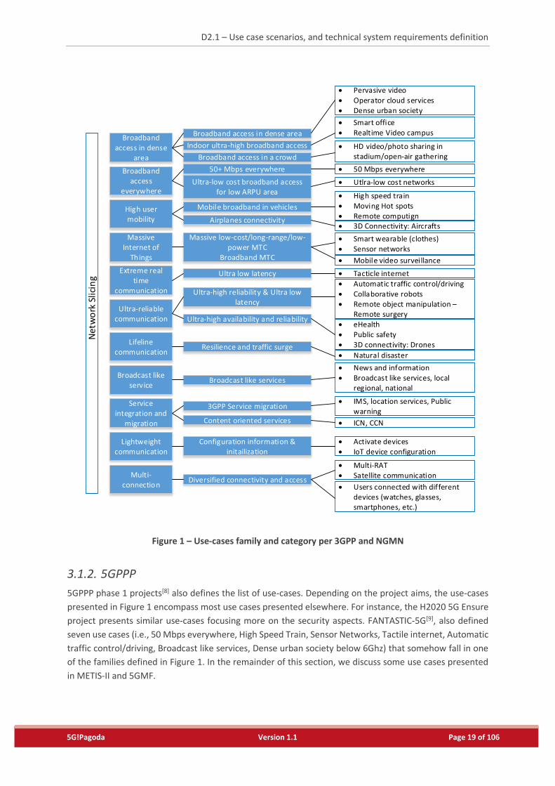
3.1.1. 3GPP and NGMN
From the viewpoints of SDO, 3GPP[6] and NGMN[7] have published documents dedicated to 5G system
use-cases. Figure 1 summarizes the 5G system use-cases defined by 3GPP and NGMN. The figure is
based on the one presented in NGMN. It also encompasses use-cases from the 3GPP document. The
details of each use-case are included in Appendix A.
The 5G system use-cases are grouped into families, and each family includes one or more categories.
Network Slicing is involved in all the use-cases as network slicing is indispensable to enable all these
use-cases concurrently over the shared physical infrastructure.
D2.1 – Use case scenarios, and technical system requirements definition
5G!Pagoda Version 1.1 Page 19 of 106
Figure 1 – Use-cases family and category per 3GPP and NGMN
3.1.2. 5GPPP
5GPPP phase 1 projects[8] also defines the list of use-cases. Depending on the project aims, the use-cases
presented in Figure 1 encompass most use cases presented elsewhere. For instance, the H2020 5G Ensure
project presents similar use-cases focusing more on the security aspects. FANTASTIC-5G[9], also defined
seven use cases (i.e., 50 Mbps everywhere, High Speed Train, Sensor Networks, Tactile internet, Automatic
traffic control/driving, Broadcast like services, Dense urban society below 6Ghz) that somehow fall in one
of the families defined in Figure 1. In the remainder of this section, we discuss some use cases presented
in METIS-II and 5GMF.
Broadband access in dense
area
Broadband access
everywhere
High user mobility
Massive Internet of
Things
Extreme real time
communication
Lifelinecommunication
Ultra-reliable communication
Broadcast like service
Service integration and
migration
Lightweight communication
Multi-connection
Net
wo
rk S
licin
g
Broadband access in dense area
Indoor ultra-high broadband access
Broadband access in a crowd
50+ Mbps everywhere
Ultra-low cost broadband access for low ARPU area
Mobile broadband in vehicles
Airplanes connectivity
Massive low-cost/long-range/low-power MTC
Broadband MTC
Ultra low latency
Resilience and traffic surge
Ultra-high reliability & Ultra low latency
Ultra-high availability and reliability
Broadcast like services
3GPP Service migration
Content oriented services
Configuration information & initailization
Diversified connectivity and access
Pervasive video
Operator cloud services Dense urban society
Smart office
Realtime Video campus
HD video/photo sharing in stadium/open-air gathering
50 Mbps everywhere
Utlra-low cost networks
High speed train Moving Hot spots Remote computign 3D Connectivity: Aircrafts
Smart wearable (clothes) Sensor networks
Tacticle internet
Mobile video surveillance
Natural disaster
Automatic traffic control/driving
Collaborative robots Remote object manipulation –
Remote surgery
eHealth Public safety 3D connectivity: Drones
IMS, location services, Public warning
ICN, CCN
News and information
Broadcast like services, local regional, national
Activate devices IoT device configuration
Multi-RAT Satellite communication
Users connected with different devices (watches, glasses, smartphones, etc.)
D2.1 – Use case scenarios, and technical system requirements definition
5G!Pagoda Version 1.1 Page 20 of 106
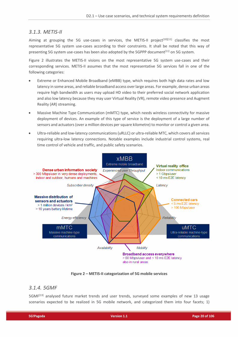
3.1.3. METIS-II
Aiming at grouping the 5G use-cases in services, the METIS-II project[10][11] classifies the most
representative 5G system use-cases according to their constraints. It shall be noted that this way of
presenting 5G system use-cases has been also adopted by the 5GPPP document[11] on 5G system.
Figure 2 illustrates the METIS-II visions on the most representative 5G system use-cases and their
corresponding services. METIS-II assumes that the most representative 5G services fall in one of the
following categories:
Extreme or Enhanced Mobile Broadband (eMBB) type, which requires both high data rates and low
latency in some areas, and reliable broadband access over large areas. For example, dense urban areas
require high bandwidth as users may upload HD video to their preferred social network application
and also low latency because they may user Virtual Reality (VR), remote video presence and Augment
Reality (AR) streaming.
Massive Machine Type Communication (mMTC) type, which needs wireless connectivity for massive
deployment of devices. An example of this type of service is the deployment of a large number of
sensors and actuators (over a million devices per square kilometre) to monitor or control a given area.
Ultra-reliable and low-latency communications (uRLLC) or ultra-reliable MTC, which covers all services
requiring ultra-low latency connections. Notable examples include industrial control systems, real
time control of vehicle and traffic, and public safety scenarios.
Figure 2 – METIS-II categorization of 5G mobile services
3.1.4. 5GMF
5GMF[13] analysed future market trends and user trends, surveyed some examples of new 13 usage
scenarios expected to be realized in 5G mobile network, and categorized them into four facets; 1)
D2.1 – Use case scenarios, and technical system requirements definition
5G!Pagoda Version 1.1 Page 21 of 106
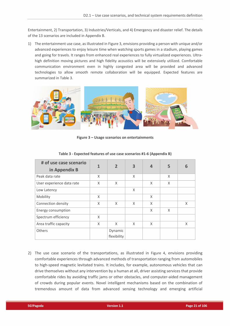
Entertainment, 2) Transportation, 3) Industries/Verticals, and 4) Emergency and disaster relief. The details
of the 13 scenarios are included in Appendix B.
1) The entertainment use case, as illustrated in Figure 3, envisions providing a person with unique and/or
advanced experiences to enjoy leisure time when watching sports games in a stadium, playing games
and going for travels. It ranges from enhanced real experiences to fully virtualized experiences. Ultra-
high definition moving pictures and high fidelity acoustics will be extensively utilized. Comfortable
communication environment even in highly congested area will be provided and advanced
technologies to allow smooth remote collaboration will be equipped. Expected features are
summarized in Table 3.
Figure 3 – Usage scenarios on entertainments
Table 3 - Expected features of use case scenarios #1-6 (Appendix B)
# of use case scenario
in Appendix B 1 2 3 4 5 6
Peak data rate X X X
User experience data rate X X X X
Low Latency X
Mobility X X
Connection density X X X X X
Energy consumption X X
Spectrum efficiency X
Area traffic capacity X X X X X
Others Dynamic
flexibility
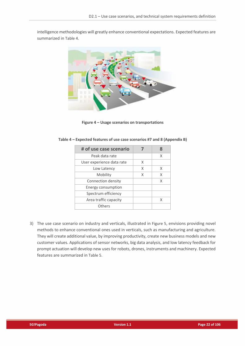
2) The use case scenario of the transportations, as illustrated in Figure 4, envisions providing
comfortable experiences through advanced methods of transportation ranging from automobiles
to high-speed magnetic levitated trains. It includes, for example, autonomous vehicles that can
drive themselves without any intervention by a human at all, driver assisting services that provide
comfortable rides by avoiding traffic jams or other obstacles, and computer-aided management
of crowds during popular events. Novel intelligent mechanisms based on the combination of
tremendous amount of data from advanced sensing technology and emerging artificial
D2.1 – Use case scenarios, and technical system requirements definition
5G!Pagoda Version 1.1 Page 22 of 106
intelligence methodologies will greatly enhance conventional expectations. Expected features are
summarized in Table 4.
Figure 4 – Usage scenarios on transportations
Table 4 – Expected features of use case scenarios #7 and 8 (Appendix B)
# of use case scenario 7 8 Peak data rate X
User experience data rate X
Low Latency X X
Mobility X X
Connection density X
Energy consumption
Spectrum efficiency
Area traffic capacity X
Others
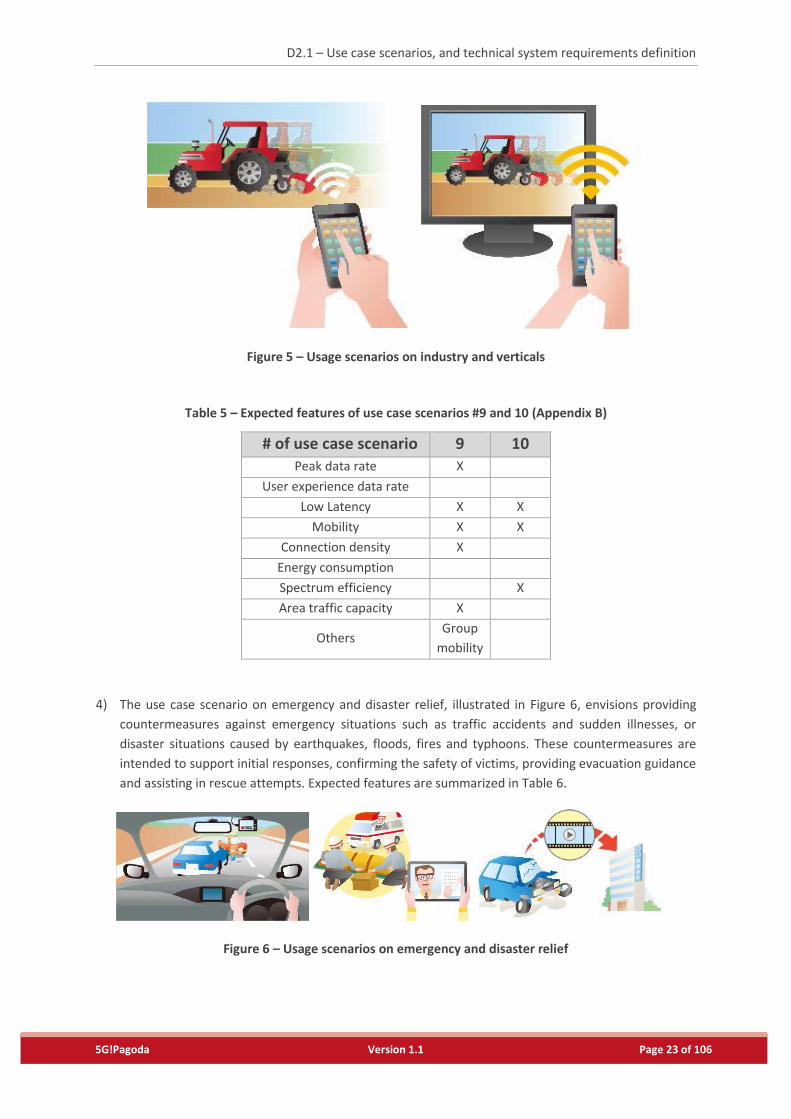
3) The use case scenario on industry and verticals, illustrated in Figure 5, envisions providing novel
methods to enhance conventional ones used in verticals, such as manufacturing and agriculture.
They will create additional value, by improving productivity, create new business models and new
customer values. Applications of sensor networks, big data analysis, and low latency feedback for
prompt actuation will develop new uses for robots, drones, instruments and machinery. Expected
features are summarized in Table 5.
D2.1 – Use case scenarios, and technical system requirements definition
5G!Pagoda Version 1.1 Page 23 of 106
Figure 5 – Usage scenarios on industry and verticals
Table 5 – Expected features of use case scenarios #9 and 10 (Appendix B)
# of use case scenario 9 10 Peak data rate X
User experience data rate
Low Latency X X
Mobility X X
Connection density X
Energy consumption
Spectrum efficiency X
Area traffic capacity X
Others Group
mobility
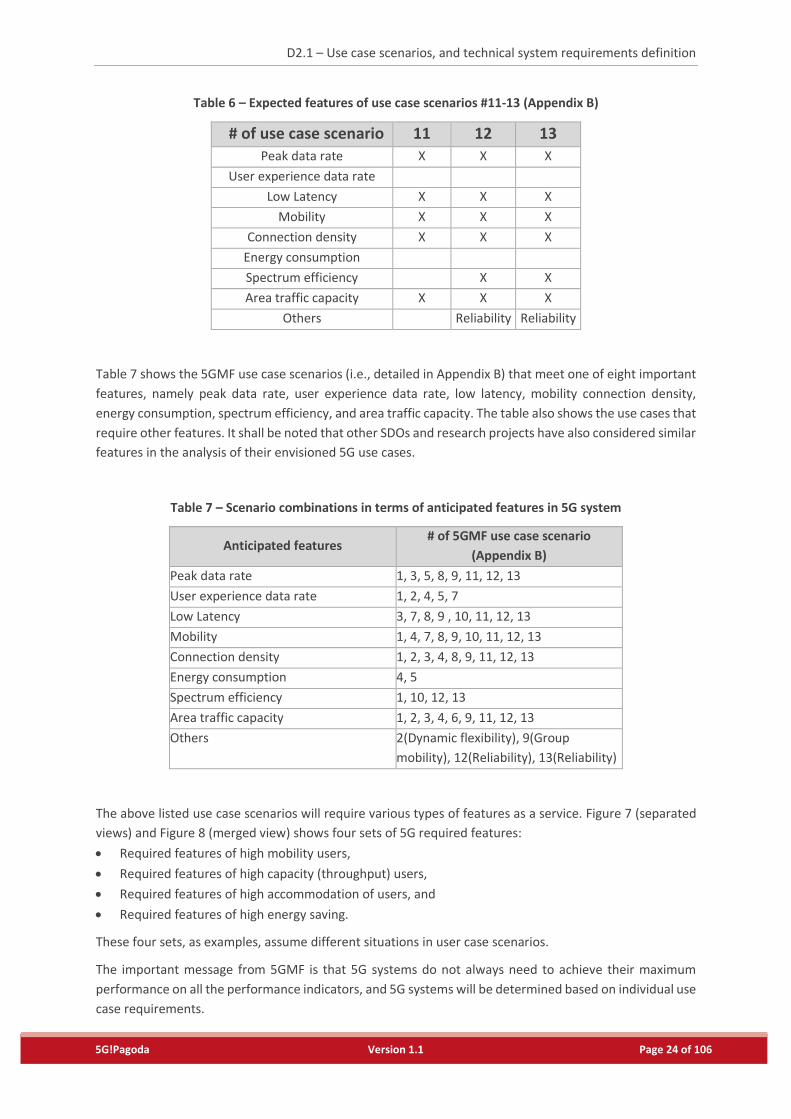
4) The use case scenario on emergency and disaster relief, illustrated in Figure 6, envisions providing
countermeasures against emergency situations such as traffic accidents and sudden illnesses, or
disaster situations caused by earthquakes, floods, fires and typhoons. These countermeasures are
intended to support initial responses, confirming the safety of victims, providing evacuation guidance
and assisting in rescue attempts. Expected features are summarized in Table 6.
Figure 6 – Usage scenarios on emergency and disaster relief
D2.1 – Use case scenarios, and technical system requirements definition
5G!Pagoda Version 1.1 Page 24 of 106
Table 6 – Expected features of use case scenarios #11-13 (Appendix B)
# of use case scenario 11 12 13
Peak data rate X X X
User experience data rate
Low Latency X X X
Mobility X X X
Connection density X X X
Energy consumption
Spectrum efficiency X X
Area traffic capacity X X X
Others Reliability Reliability
Table 7 shows the 5GMF use case scenarios (i.e., detailed in Appendix B) that meet one of eight important
features, namely peak data rate, user experience data rate, low latency, mobility connection density,
energy consumption, spectrum efficiency, and area traffic capacity. The table also shows the use cases that
require other features. It shall be noted that other SDOs and research projects have also considered similar
features in the analysis of their envisioned 5G use cases.
Table 7 – Scenario combinations in terms of anticipated features in 5G system
Anticipated features # of 5GMF use case scenario
(Appendix B)
Peak data rate 1, 3, 5, 8, 9, 11, 12, 13
User experience data rate 1, 2, 4, 5, 7
Low Latency 3, 7, 8, 9 , 10, 11, 12, 13
Mobility 1, 4, 7, 8, 9, 10, 11, 12, 13
Connection density 1, 2, 3, 4, 8, 9, 11, 12, 13
Energy consumption 4, 5
Spectrum efficiency 1, 10, 12, 13
Area traffic capacity 1, 2, 3, 4, 6, 9, 11, 12, 13
Others 2(Dynamic flexibility), 9(Group
mobility), 12(Reliability), 13(Reliability)
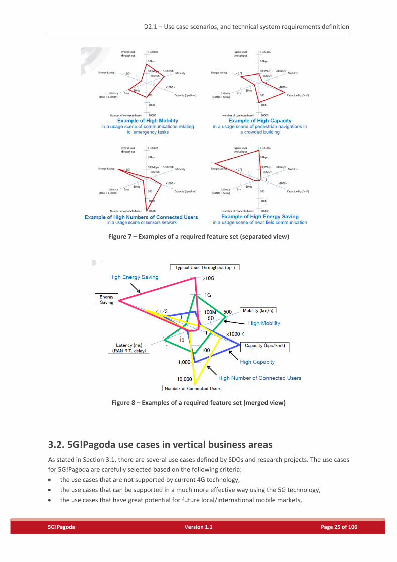
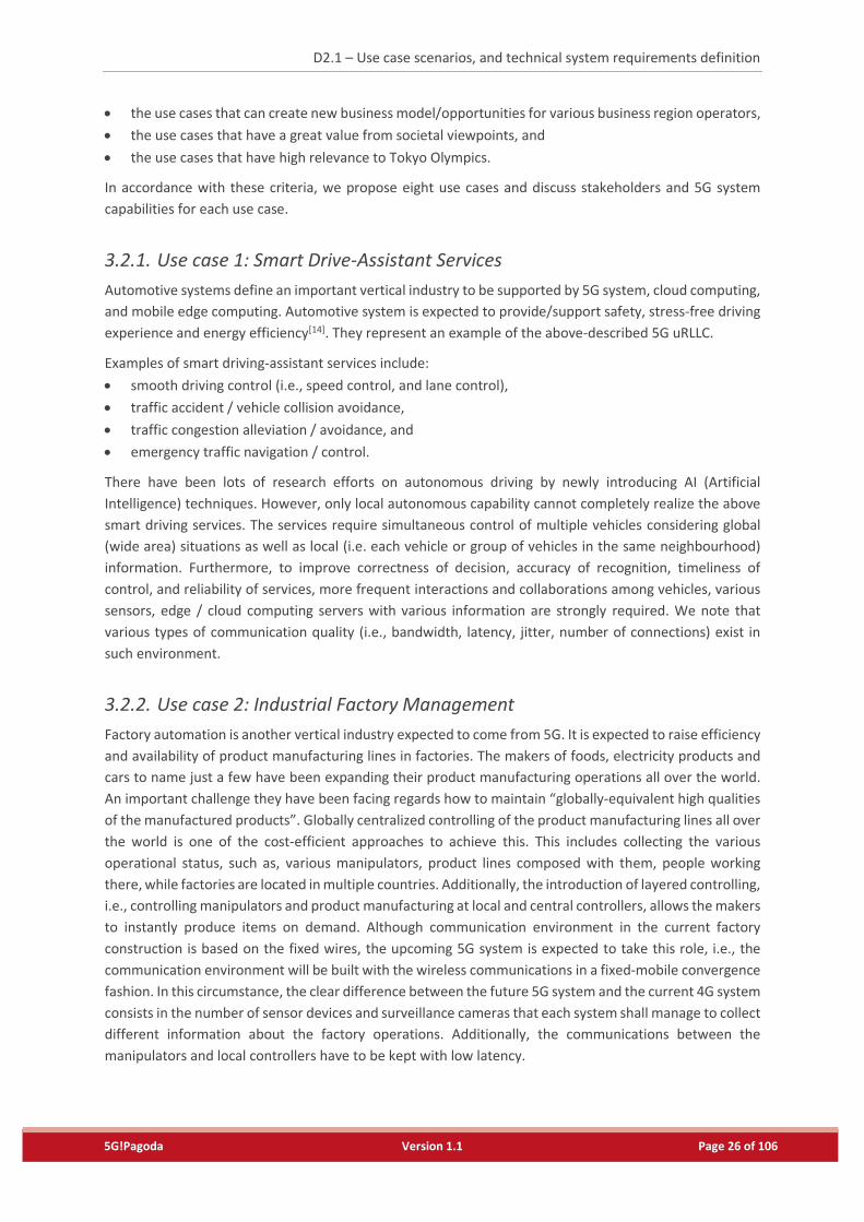
The above listed use case scenarios will require various types of features as a service. Figure 7 (separated
views) and Figure 8 (merged view) shows four sets of 5G required features:
Required features of high mobility users,
Required features of high capacity (throughput) users,
Required features of high accommodation of users, and
Required features of high energy saving.
These four sets, as examples, assume different situations in user case scenarios.
The important message from 5GMF is that 5G systems do not always need to achieve their maximum
performance on all the performance indicators, and 5G systems will be determined based on individual use
case requirements.
D2.1 – Use case scenarios, and technical system requirements definition
5G!Pagoda Version 1.1 Page 25 of 106
Figure 7 – Examples of a required feature set (separated view)
Figure 8 – Examples of a required feature set (merged view)
3.2. 5G!Pagoda use cases in vertical business areas
As stated in Section 3.1, there are several use cases defined by SDOs and research projects. The use cases
for 5G!Pagoda are carefully selected based on the following criteria:
the use cases that are not supported by current 4G technology,
the use cases that can be supported in a much more effective way using the 5G technology,
the use cases that have great potential for future local/international mobile markets,
D2.1 – Use case scenarios, and technical system requirements definition
5G!Pagoda Version 1.1 Page 26 of 106
the use cases that can create new business model/opportunities for various business region operators,
the use cases that have a great value from societal viewpoints, and
the use cases that have high relevance to Tokyo Olympics.
In accordance with these criteria, we propose eight use cases and discuss stakeholders and 5G system
capabilities for each use case.
3.2.1. Use case 1: Smart Drive-Assistant Services
Automotive systems define an important vertical industry to be supported by 5G system, cloud computing,
and mobile edge computing. Automotive system is expected to provide/support safety, stress-free driving
experience and energy efficiency[14]. They represent an example of the above-described 5G uRLLC.
Examples of smart driving-assistant services include:
smooth driving control (i.e., speed control, and lane control),
traffic accident / vehicle collision avoidance,
traffic congestion alleviation / avoidance, and
emergency traffic navigation / control.
There have been lots of research efforts on autonomous driving by newly introducing AI (Artificial
Intelligence) techniques. However, only local autonomous capability cannot completely realize the above
smart driving services. The services require simultaneous control of multiple vehicles considering global
(wide area) situations as well as local (i.e. each vehicle or group of vehicles in the same neighbourhood)
information. Furthermore, to improve correctness of decision, accuracy of recognition, timeliness of
control, and reliability of services, more frequent interactions and collaborations among vehicles, various
sensors, edge / cloud computing servers with various information are strongly required. We note that
various types of communication quality (i.e., bandwidth, latency, jitter, number of connections) exist in
such environment.
3.2.2. Use case 2: Industrial Factory Management
Factory automation is another vertical industry expected to come from 5G. It is expected to raise efficiency
and availability of product manufacturing lines in factories. The makers of foods, electricity products and
cars to name just a few have been expanding their product manufacturing operations all over the world.
An important challenge they have been facing regards how to maintain “globally-equivalent high qualities
of the manufactured products”. Globally centralized controlling of the product manufacturing lines all over
the world is one of the cost-efficient approaches to achieve this. This includes collecting the various
operational status, such as, various manipulators, product lines composed with them, people working
there, while factories are located in multiple countries. Additionally, the introduction of layered controlling,
i.e., controlling manipulators and product manufacturing at local and central controllers, allows the makers
to instantly produce items on demand. Although communication environment in the current factory
construction is based on the fixed wires, the upcoming 5G system is expected to take this role, i.e., the
communication environment will be built with the wireless communications in a fixed-mobile convergence
fashion. In this circumstance, the clear difference between the future 5G system and the current 4G system
consists in the number of sensor devices and surveillance cameras that each system shall manage to collect
different information about the factory operations. Additionally, the communications between the
manipulators and local controllers have to be kept with low latency.
D2.1 – Use case scenarios, and technical system requirements definition
5G!Pagoda Version 1.1 Page 27 of 106
3.2.3. Use case 3: Ensuring QoS On Demand
Due to the advancements of the transportation technologies, people visit various places. This results in hot
spots, i.e., network areas with very high user density varying over time. In these hot spots, high date rate
network capability in ultra-high connection density should be provided by operators. Current mobile
systems provide much less throughput in a situation of high connection density, e.g., provides only 700
Kbit/s due to static (24/7) resource assignments.
In case of a large-scale sports event, such as the 2020 Tokyo Olympics, more than eighty thousand people
are expected to attend the Olympic opening ceremony. Some audiences may share HD live videos (i.e.,
Facebook live) with friends and relative far way. Some may take HD/360 photos and post them on Facebook
or Instagram. Such applications require high data rate. The events normally last just a few hours (or may
be a few weeks during Olympic), the operators do not need to provide ultra-high network capacity for 24/7.
The required network capacity needs to be provided on demand. Operators can get the events information
in advance and prepare to meet the requirements during the events and, they may scale down the network
capacity after the events.
A group of moving vehicles or crowds (e.g., moving mass events such as in case of marathon or long-
distance cycling tournaments) will generate capacity variation over space due to the use of ultra-high (4K
or more) definition video streaming. There will be hundreds/thousands of participants for such events.
Also, the audiences along the route may take photos/videos and share them on social networks. The
capacity demand would be as high as a stadium scenario, yet the hot spots may be moving at a speed of
20~100 km/h. The operators need to realize dynamic and real-time provisioning capacity for these areas
with a high density of users moving fast.
3.2.4. Use case 4: Smart/Virtual Office
In the near future, there is no doubt that our work places would be a lot smarter than todays’. Most of the
devices will be wirelessly connected and office workers (communication service users) will be able to
control or adjust their working environment (like adjusting lighting and heating) via their smart phones or
any devices belonging to them (e.g., smart watches). Some immersive technologies, like 3-D or augmented
reality, will enable fully interactive business meetings and people from all over the world can join the
meeting as if they are in the same room. It is even possible not to have an actual office place as office
workers do the office stuffs, like file sharing and/or reporting, via a secured cloud.
A few examples of the smart / virtual office services that have different requirements are:
Smart environment control for comfort and energy savings;
Reliable security alarm: fire alarm, intrusion alarm;
Support of employee productivity, with shared space, interactive tools and online resources;
Support for remote and online collaboration;
Privacy and data protection.
In fact, Smart/Virtual office is not a new concept. Smart buildings with sensors and actuators for comfort
monitoring are increasing and many products to support remote collaboration among employees are
coming to the market. However, it is not yet supported to connect the pieces together, and there are many
technical challenges to make the scenario real and effective.
For example, when CO2 detecting sensors measure a value of CO2 exceeding a specific threshold, priority
data for the detection must be sent from the sensors to a centralized server in the cloud, and the priority
data from the server to the actuators, installed inside the smart building, must be delivered with low-
D2.1 – Use case scenarios, and technical system requirements definition
5G!Pagoda Version 1.1 Page 28 of 106
latency and high reliability. The alarm message to the building managers and employees should be
delivered in the different channel with different QoS characteristics. For a 3D meeting, wearable device of
participants (e.g., smart watch) manage the meeting schedule, and the sensors on a smart chair adjusts the
comfort level of the person. High-demand video data must be transferred in real-time in a secure channel.
Employees will also be mobile, agnostically working from the office, from their home or while travelling.
This requires secured VPN access to local resources as well as adaptive plan and use of office space.
The adoption of the European General Data Protection regulation also brings new requirements: while the
smart office will be more and more connected, the data protection requirements will increase. Use of local
server, Mobile Edge Computing and online authentication servers will be considered.
Finally, 5G should evolve in a way to glue the separate pieces of IoT, wireless, 3D, cloud, and their related
technologies into a big picture with dynamic slicing of the network.
3.2.5. Use case 5: Contents Delivery Network as a Service
Over the last decade, content delivery networks (CDNs) have played a vital role in hosting and distributing
content to users. Thanks to its architecture that consists of multiple servers distributed geographically, a
content is replicated across a wide area and accordingly becomes highly available. Several studies have
demonstrated the effectiveness of CDNs in improving the quality-of-experience (QoE) by making access to
applications and services faster and more reliable. This concept has helped many renowned companies to
develop and to expand their revenue. CDNs can improve the access by caching and streaming content, with
many distributed components collaborating to deliver contents across different network nodes. CDN
providers have general and distributed topologies around the world. Hence, for CDN providers, there are
two types of users:
- CDN customers renting CDN servers to host their content, and
- CDN end-users who download content from CDN.
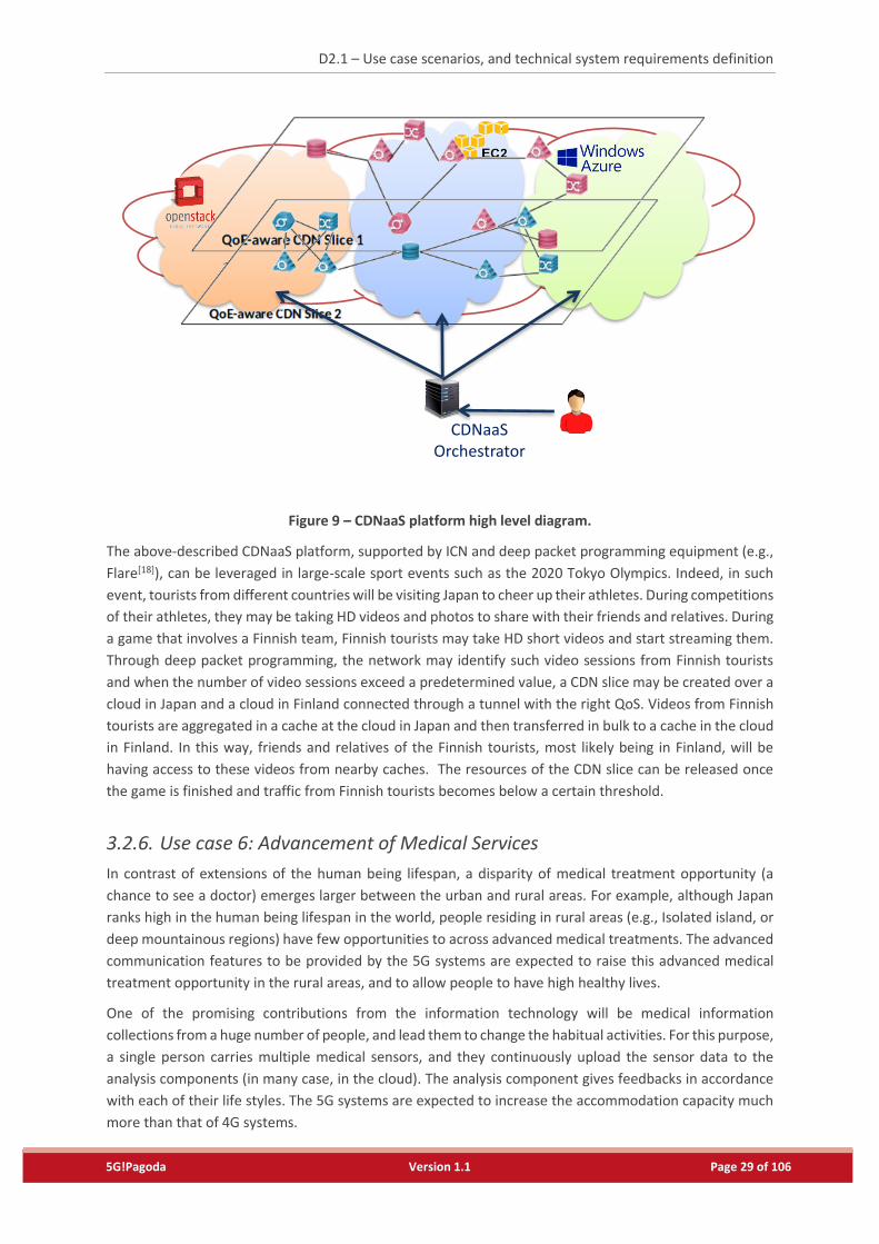
The idea of CDN as a service (CDNaaS) platform is the offer of a tool that allows different CDN customers
to create their CDN slices, on top of different cloud networks, without writing a single line of code or
deploying any server. Figure 9 shows the main idea beneath the envisioned CDNaaS platform. As depicted
in this figure, the created CDN slice will run on different cloud network and that for serving many users
around the globe and by offering CDNs with high QoE. Using a dedicated entity, dubbed CDN orchestrator,
a CDN customer may create a federated CDN consisting of different CDN slices created over different cloud
domains across different countries (e.g., Amazon Japan, Azure Europe, etc.). The CDNaaS platform shall be
designed with the maximum level of flexibility for integrating with different public and private
infrastructure as a service (IaaS) providers such as Amazon AWS service, Microsoft Azure, Rackspace and
OpenStack-managed clouds in order to host different CDNaaS components. The CDNaaS platform may be
further improved integrating ICN algorithms and mechanisms for the purpose of smart caching. It may be
also considered to use ICN network as the final distribution network from the dynamically placed CDN
content server to users to further reduce the network traffic and the response time.
D2.1 – Use case scenarios, and technical system requirements definition
5G!Pagoda Version 1.1 Page 29 of 106
Figure 9 – CDNaaS platform high level diagram.
The above-described CDNaaS platform, supported by ICN and deep packet programming equipment (e.g.,
Flare[18]), can be leveraged in large-scale sport events such as the 2020 Tokyo Olympics. Indeed, in such
event, tourists from different countries will be visiting Japan to cheer up their athletes. During competitions
of their athletes, they may be taking HD videos and photos to share with their friends and relatives. During
a game that involves a Finnish team, Finnish tourists may take HD short videos and start streaming them.
Through deep packet programming, the network may identify such video sessions from Finnish tourists
and when the number of video sessions exceed a predetermined value, a CDN slice may be created over a
cloud in Japan and a cloud in Finland connected through a tunnel with the right QoS. Videos from Finnish
tourists are aggregated in a cache at the cloud in Japan and then transferred in bulk to a cache in the cloud
in Finland. In this way, friends and relatives of the Finnish tourists, most likely being in Finland, will be
having access to these videos from nearby caches. The resources of the CDN slice can be released once
the game is finished and traffic from Finnish tourists becomes below a certain threshold.
3.2.6. Use case 6: Advancement of Medical Services
In contrast of extensions of the human being lifespan, a disparity of medical treatment opportunity (a
chance to see a doctor) emerges larger between the urban and rural areas. For example, although Japan
ranks high in the human being lifespan in the world, people residing in rural areas (e.g., Isolated island, or
deep mountainous regions) have few opportunities to across advanced medical treatments. The advanced
communication features to be provided by the 5G systems are expected to raise this advanced medical
treatment opportunity in the rural areas, and to allow people to have high healthy lives.
One of the promising contributions from the information technology will be medical information
collections from a huge number of people, and lead them to change the habitual activities. For this purpose,
a single person carries multiple medical sensors, and they continuously upload the sensor data to the
analysis components (in many case, in the cloud). The analysis component gives feedbacks in accordance
with each of their life styles. The 5G systems are expected to increase the accommodation capacity much
more than that of 4G systems.
CDNaaS Orchestrator
D2.1 – Use case scenarios, and technical system requirements definition
5G!Pagoda Version 1.1 Page 30 of 106
Additionally, the 5G systems may contribute the opportunity of advanced medical treatment in a more
direct manner, that is, enhancing the surgery support system resulting in allowing patients to have remote
medical surgeries. The current (4G) mobile systems have two shortcomings for remote surgery: low
throughput and long communication delay. The low throughput obstacles high-resolution video used in
remote surgery, or increases the tremendous delay in surgery operational interaction between the
surgeon’s action and the reaction of surgery support system, due to needs of the high-rate
encode/decoding of the high-resolution video. The communication delay (the second shortcoming) should
also be shortened to a few milliseconds. In a surgery scenario, the reasonable communication delay is 100
milliseconds at maximum, and this can be treated by the 4G (current) mobile systems. However, the
remote medical surgery will need to be well-supported by the local manipulators to autonomously work in
a small movement in the surgery operations. In this autonomous works, the manipulator equips multiple
sensors and reacts from the sensed data, such as, temperature of human tissue, organ’s movement, blood
pressure, etc. This feedback mechanism requires 1-5 milliseconds in the end-to-end communications.
Simultaneously, the surgery operation is monitored by an artificial intelligence (AI) technology in order to
allow AI, in the future, to take some parts of surgery operations done by the surgeon.
3.2.7. Use case 7: Massive IoT
One of the most promising domains for the extension of the 5G systems is the efficient service support for
a massive number of devices. With this, a complete new ecosystem is created, in which a large amount of
data is collected from the environment and processed and a set of ultra-reliable actuation commands. For
this, a large number of sensors and actuators are deployed in the network, either statically or mobile
enabling the integration with the real environments.
The massive IoT use case encapsulates for a very large number of applications and domains, including
eHealth, Smart Cities, remote control and enhanced map information. This results in a set of use cases with
different cost possibilities, resource allocation and mobility requirements, authentication possibilities,
resilience and security. A set of relevant situations for this use case are described underneath:
Very efficient connectivity – a large number of sensors will be embedded in buildings. For these
sensors, the cost of connectivity should be very small. Additionally, the energy consumption should
allow for 10-year battery life time, requiring minimal communication to the network. Security and
resilience of communication are less important, however being possibly the added value when the
technology is mature.
Ultra-reliable connectivity – even though with some delay (e.g. 500ms), the actuation to some specific
sensors has to happen, as in the case of energy transformers remote control in smart grids.
Ultra-secure connectivity – some sensitive information, such as street sensors and video cameras may
require to have a larger security level than the usual connectivity.
Ultra-secure, low delay connectivity – specific information such as emergency situations should be
transmitted with a low delay to the network.
3.2.8. Use case 8: Disaster handling
It is expected that the 5G mobile networks, based on slicing, will be used for multiple purposes (as
described in previous sections of this deliverable). These networks (slices) will share common
infrastructure that provides necessary resources to build slices. In case of disaster (e.g., earthquake, and
tsunami) some of the existing communication solutions can be unusable or provide significantly degraded
D2.1 – Use case scenarios, and technical system requirements definition
5G!Pagoda Version 1.1 Page 31 of 106
services. Moreover, in such situations there may be a need to provide additional emergency related
services (e.g., medical, police, fire brigades, etc.) – in short, an emergency slice. There is a need of providing
resources to build such ‘emergency slice’, that is a slice for which resources allocation should have the
highest priority. In order to provide these resources, slices related to entertainment services can be
removed, some other slices that have to be operational (e.g., smart city specific IoT, voice communication,
etc.) can be switched to the emergency mode, that provide their proper functionality, but with minimal
consumption of resources. This use-case requires the capability of the creation of a slice on-demand,
description about slice requirements in emergency situations and their capability to work in the above
mentioned emergency mode.
3.3. Stakeholders
3.3.1. Use case 1: Smart Drive-Assistant Services
The major stakeholders of the smart drive-assistant services in 5G-Pagoda perspective are:
Vehicle consumers,
Automotive companies,
ITS service providers,
Public information service providers,
Wireless communication service providers (MNO, MVNO), and
Cloud service providers.
They have their own business and system/resource utilization policies, and it should be assumed that
multiple providers (companies) are under competitive and/or collaborative situations. From the viewpoint
of networking and computing technology, the wireless communication service providers and cloud service
providers will have important roles for optimizing resources, improving total service reliability, and efficient
interactions and collaboration among all stakeholders.
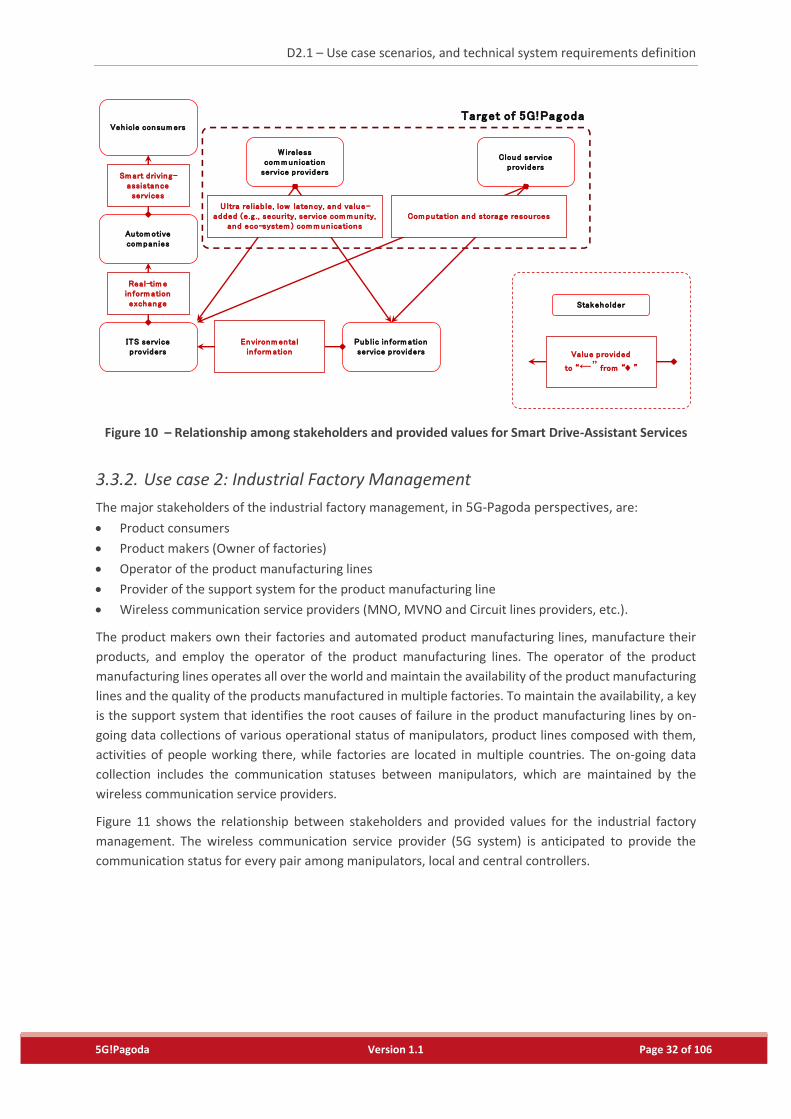
Figure 10 shows the relationship among stakeholders, and provided values for the smart drive-assistant
services. 5G!Pagoda will demonstrate interactions of the whole system, and especially validate challenging
network slicing technologies focusing on novel capabilities in the wireless communication service providers
and cloud service providers.
D2.1 – Use case scenarios, and technical system requirements definition
5G!Pagoda Version 1.1 Page 32 of 106
Figure 10 – Relationship among stakeholders and provided values for Smart Drive-Assistant Services
3.3.2. Use case 2: Industrial Factory Management
The major stakeholders of the industrial factory management, in 5G-Pagoda perspectives, are:
Product consumers
Product makers (Owner of factories)
Operator of the product manufacturing lines
Provider of the support system for the product manufacturing line
Wireless communication service providers (MNO, MVNO and Circuit lines providers, etc.).
The product makers own their factories and automated product manufacturing lines, manufacture their
products, and employ the operator of the product manufacturing lines. The operator of the product
manufacturing lines operates all over the world and maintain the availability of the product manufacturing
lines and the quality of the products manufactured in multiple factories. To maintain the availability, a key
is the support system that identifies the root causes of failure in the product manufacturing lines by on-
going data collections of various operational status of manipulators, product lines composed with them,
activities of people working there, while factories are located in multiple countries. The on-going data
collection includes the communication statuses between manipulators, which are maintained by the
wireless communication service providers.
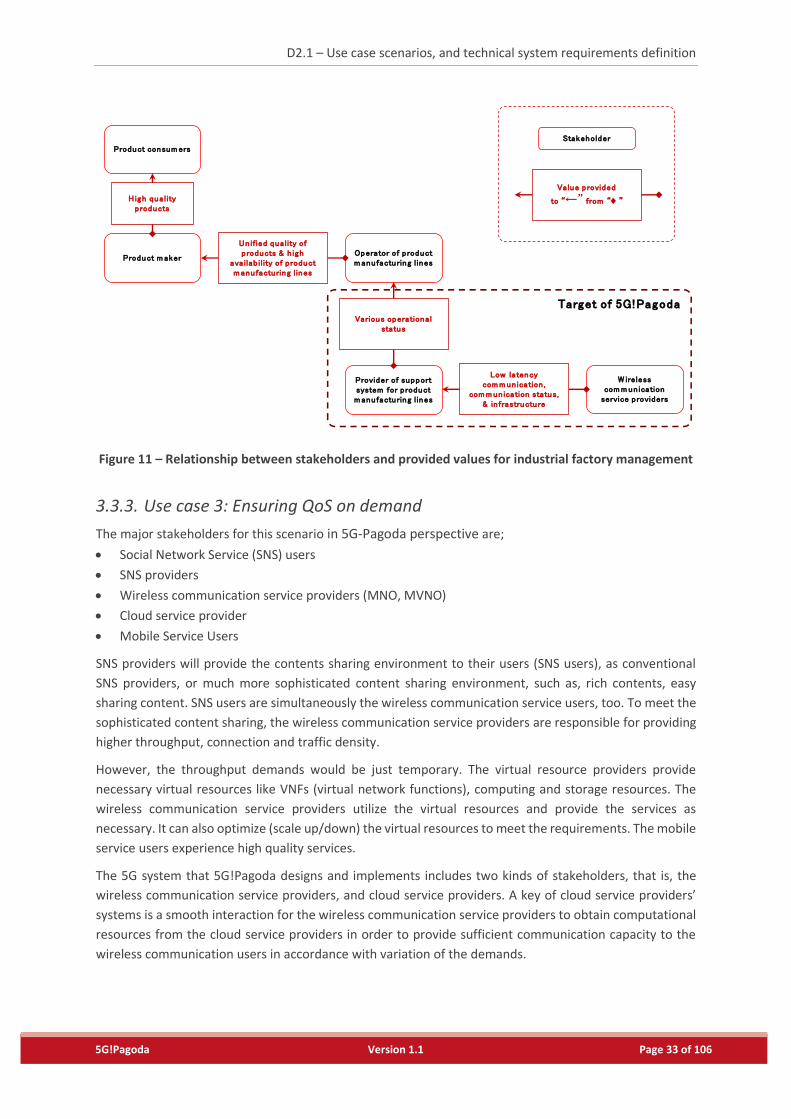
Figure 11 shows the relationship between stakeholders and provided values for the industrial factory
management. The wireless communication service provider (5G system) is anticipated to provide the
communication status for every pair among manipulators, local and central controllers.
Autom otive com pan ies
W ireless com m un ication
service providers
Veh icle consum ers
Sm art driving-assistance services
Value provided
to “←” from “♦ ”
Stakeholder
Target of 5G!Pagoda
Cloud service providers
ITS service providers
Real-tim e in form ation exchange
Pub lic in form ation service providers
Environm enta l in form ation
U ltra reliab le, low latency, and va lue-added (e.g . , security, service com m un ity,
and eco-system ) com m un icationsCom putation and storage resources
D2.1 – Use case scenarios, and technical system requirements definition
5G!Pagoda Version 1.1 Page 33 of 106
Figure 11 – Relationship between stakeholders and provided values for industrial factory management
3.3.3. Use case 3: Ensuring QoS on demand
The major stakeholders for this scenario in 5G-Pagoda perspective are;
Social Network Service (SNS) users
SNS providers
Wireless communication service providers (MNO, MVNO)
Cloud service provider
Mobile Service Users
SNS providers will provide the contents sharing environment to their users (SNS users), as conventional
SNS providers, or much more sophisticated content sharing environment, such as, rich contents, easy
sharing content. SNS users are simultaneously the wireless communication service users, too. To meet the
sophisticated content sharing, the wireless communication service providers are responsible for providing
higher throughput, connection and traffic density.
However, the throughput demands would be just temporary. The virtual resource providers provide
necessary virtual resources like VNFs (virtual network functions), computing and storage resources. The
wireless communication service providers utilize the virtual resources and provide the services as
necessary. It can also optimize (scale up/down) the virtual resources to meet the requirements. The mobile
service users experience high quality services.
The 5G system that 5G!Pagoda designs and implements includes two kinds of stakeholders, that is, the
wireless communication service providers, and cloud service providers. A key of cloud service providers’
systems is a smooth interaction for the wireless communication service providers to obtain computational
resources from the cloud service providers in order to provide sufficient communication capacity to the
wireless communication users in accordance with variation of the demands.
Product m akerOperator of product m anufacturing l ines
Provider of support system for product m anufacturing l ines
W ireless com m un ication
service providers
Product consum ers
H igh qua lity products
Un ified quality of products & h igh
availab il ity of product m anufacturing l ines
Various operational status
Low latency com m un ication ,
com m un ication status,& in frastructure
Value provided
to “←” from “♦ ”
Stakeholder
Target of 5G!Pagoda
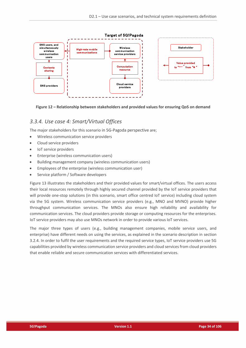
D2.1 – Use case scenarios, and technical system requirements definition
5G!Pagoda Version 1.1 Page 34 of 106
Figure 12 – Relationship between stakeholders and provided values for ensuring QoS on demand
3.3.4. Use case 4: Smart/Virtual Offices
The major stakeholders for this scenario in 5G-Pagoda perspective are;
Wireless communication service providers
Cloud service providers
IoT service providers
Enterprise (wireless communication users)
Building management company (wireless communication users)
Employees of the enterprise (wireless communication user)
Service platform / Software developers
Figure 13 illustrates the stakeholders and their provided values for smart/virtual offices. The users access
their local resources remotely through highly secured channel provided by the IoT service providers that
will provide one-stop solutions (in this scenario, smart office centred IoT service) including cloud system
via the 5G system. Wireless communication service providers (e.g., MNO and MVNO) provide higher
throughput communication services. The MNOs also ensure high reliability and availability for
communication services. The cloud providers provide storage or computing resources for the enterprises.
IoT service providers may also use MNOs network in order to provide various IoT services.
The major three types of users (e.g., building management companies, mobile service users, and
enterprise) have different needs on using the services, as explained in the scenario description in section
3.2.4. In order to fulfil the user requirements and the required service types, IoT service providers use 5G
capabilities provided by wireless communication service providers and cloud services from cloud providers
that enable reliable and secure communication services with differentiated services.
SNS providers
W ireless com m un ication
service p roviders
SNS users, and sim u ltaneously
w ireless com m un ication
users
Contentssharing
H igh-rate m ob ile com m un ications
Value provided
to “←” from “♦ ”
Stakeholder
Target of 5G!Pagoda
Cloud service providers
Com putation resource
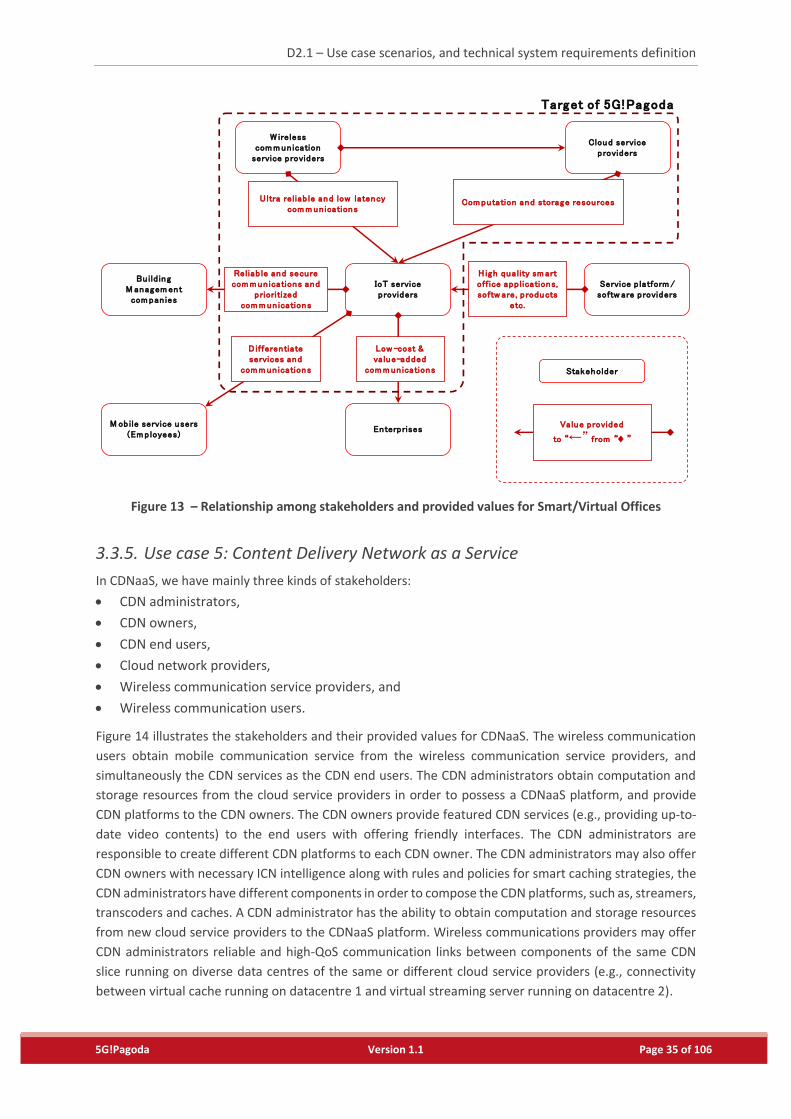
D2.1 – Use case scenarios, and technical system requirements definition
5G!Pagoda Version 1.1 Page 35 of 106
Figure 13 – Relationship among stakeholders and provided values for Smart/Virtual Offices
3.3.5. Use case 5: Content Delivery Network as a Service
In CDNaaS, we have mainly three kinds of stakeholders:
CDN administrators,
CDN owners,
CDN end users,
Cloud network providers,
Wireless communication service providers, and
Wireless communication users.
Figure 14 illustrates the stakeholders and their provided values for CDNaaS. The wireless communication
users obtain mobile communication service from the wireless communication service providers, and
simultaneously the CDN services as the CDN end users. The CDN administrators obtain computation and
storage resources from the cloud service providers in order to possess a CDNaaS platform, and provide
CDN platforms to the CDN owners. The CDN owners provide featured CDN services (e.g., providing up-to-
date video contents) to the end users with offering friendly interfaces. The CDN administrators are
responsible to create different CDN platforms to each CDN owner. The CDN administrators may also offer
CDN owners with necessary ICN intelligence along with rules and policies for smart caching strategies, the
CDN administrators have different components in order to compose the CDN platforms, such as, streamers,
transcoders and caches. A CDN administrator has the ability to obtain computation and storage resources
from new cloud service providers to the CDNaaS platform. Wireless communications providers may offer
CDN administrators reliable and high-QoS communication links between components of the same CDN
slice running on diverse data centres of the same or different cloud service providers (e.g., connectivity
between virtual cache running on datacentre 1 and virtual streaming server running on datacentre 2).
Value provided
to “←” from “♦ ”
Stakeholder
Bu ild ing M anagem ent com pan ies
W ireless com m un ication
service providers
Target of 5G!Pagoda
Cloud service providers
IoT service providers
Reliab le and secure com m un ications and
prioritized com m un ications
Service p latform / softw are providers
H igh quality sm art office app lications, softw are, products
etc.
U ltra reliab le and low latency com m un ications
Com putation and storage resources
Enterprises
Low -cost & value-added
com m un ications
M ob ile service users(Em ployees)
D ifferentiate services and
com m un ications
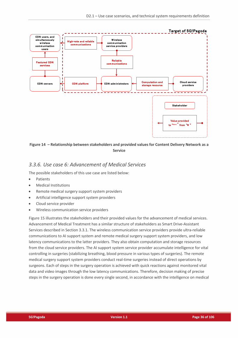
D2.1 – Use case scenarios, and technical system requirements definition
5G!Pagoda Version 1.1 Page 36 of 106
Figure 14 – Relationship between stakeholders and provided values for Content Delivery Network as a
Service
3.3.6. Use case 6: Advancement of Medical Services
The possible stakeholders of this use case are listed below:
Patients
Medical Institutions
Remote medical surgery support system providers
Artificial intelligence support system providers
Cloud service provider
Wireless communication service providers
Figure 15 illustrates the stakeholders and their provided values for the advancement of medical services.
Advancement of Medical Treatment has a similar structure of stakeholders as Smart Drive-Assistant
Services described in Section 3.3.1. The wireless communication service providers provide ultra-reliable
communications to AI support system and remote medical surgery support system providers, and low
latency communications to the latter providers. They also obtain computation and storage resources
from the cloud service providers. The AI support system service provider accumulate intelligence for vital
controlling in surgeries (stabilizing breathing, blood pressure in various types of surgeries). The remote
medical surgery support system providers conduct real-time surgeries instead of direct operations by
surgeons. Each of steps in the surgery operation is achieved with quick reactions against monitored vital
data and video images through the low latency communications. Therefore, decision making of precise
steps in the surgery operation is done every single second, in accordance with the intelligence on medical
Value provided
to “←” from “♦ ”
Stakeholder
W ireless com m un ication
service providers
CDN users, and sim u ltaneously
w ireless com m un ication
users
Target of 5G!Pagoda
CDN ow ners
Featured CDN services
H igh-rate and reliab le com m un ications
CDN adm in istratorsCDN p latformCloud service
providersCom putation and storage resource
Reliab le com m un ications
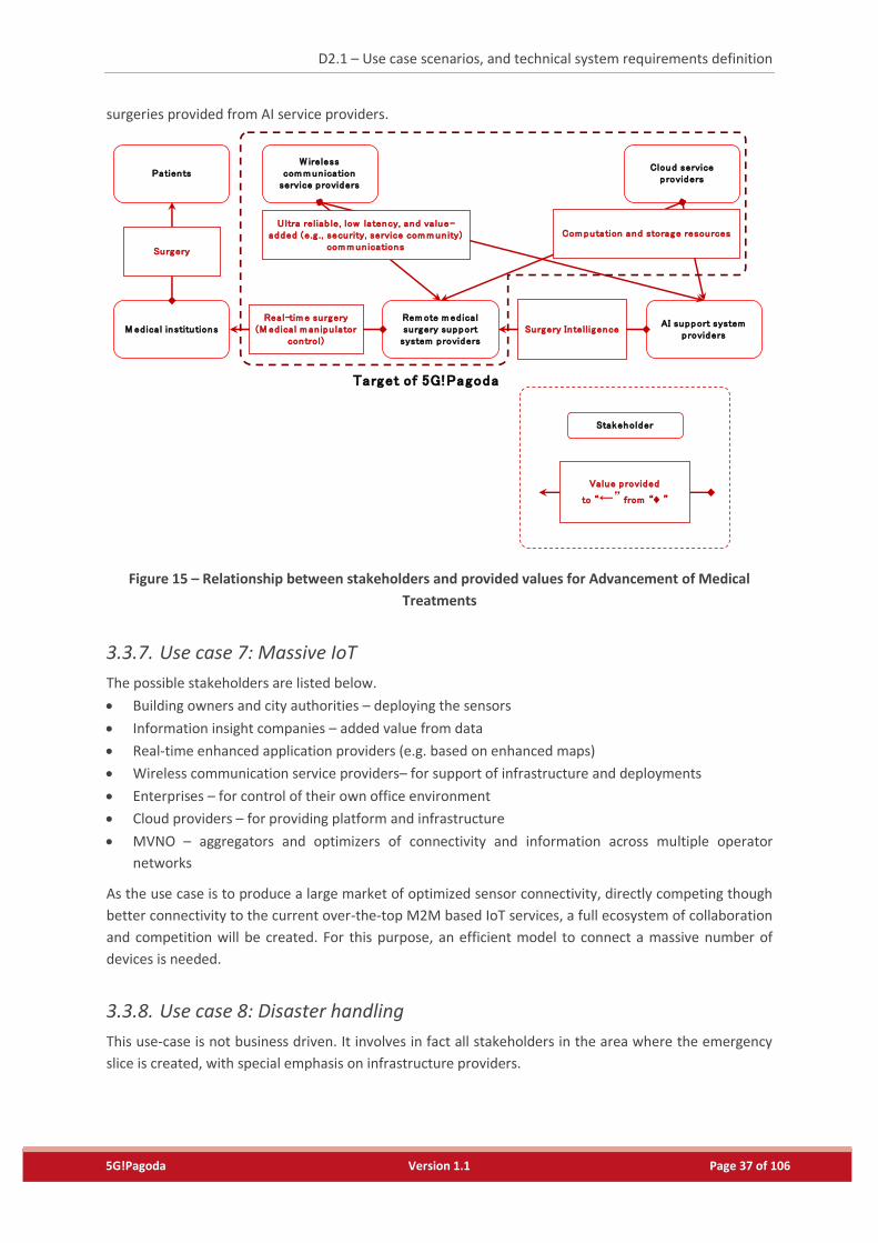
D2.1 – Use case scenarios, and technical system requirements definition
5G!Pagoda Version 1.1 Page 37 of 106
surgeries provided from AI service providers.
Figure 15 – Relationship between stakeholders and provided values for Advancement of Medical
Treatments
3.3.7. Use case 7: Massive IoT
The possible stakeholders are listed below.
Building owners and city authorities – deploying the sensors
Information insight companies – added value from data
Real-time enhanced application providers (e.g. based on enhanced maps)
Wireless communication service providers– for support of infrastructure and deployments
Enterprises – for control of their own office environment
Cloud providers – for providing platform and infrastructure
MVNO – aggregators and optimizers of connectivity and information across multiple operator
networks
As the use case is to produce a large market of optimized sensor connectivity, directly competing though
better connectivity to the current over-the-top M2M based IoT services, a full ecosystem of collaboration
and competition will be created. For this purpose, an efficient model to connect a massive number of
devices is needed.
3.3.8. Use case 8: Disaster handling
This use-case is not business driven. It involves in fact all stakeholders in the area where the emergency
slice is created, with special emphasis on infrastructure providers.
Value provided
to “←” from “♦ ”
Stakeholder
M ed ica l institutions
W ireless com m un ication
service p rovidersPatients
Surgery
Target of 5G!Pagoda
Cloud service p roviders
Rem ote m ed ica l su rgery support
system providers
Real-tim e surgery(M ed ica l m an ipu lator
control)
AI support system providers
Surgery In tell igence
U ltra reliab le, low latency, and va lue-added (e.g . , security, service com m un ity)
com m un ications
Com putation and storage resources
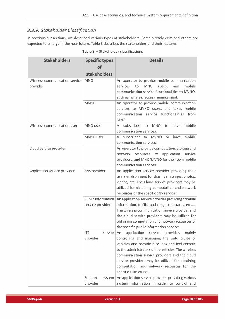
D2.1 – Use case scenarios, and technical system requirements definition
5G!Pagoda Version 1.1 Page 38 of 106
3.3.9. Stakeholder Classification
In previous subsections, we described various types of stakeholders. Some already exist and others are
expected to emerge in the near future. Table 8 describes the stakeholders and their features.
Table 8 – Stakeholder classifications
Stakeholders Specific types
of
stakeholders
Details
Wireless communication service
provider
MNO An operator to provide mobile communication
services to MNO users, and mobile
communication service functionalities to MVNO,
such as, wireless access management.
MVNO An operator to provide mobile communication
services to MVNO users, and takes mobile
communication service functionalities from
MNO.
Wireless communication user MNO user A subscriber to MNO to have mobile
communication services.
MVNO user A subscriber to MVNO to have mobile
communication services.
Cloud service provider An operator to provide computation, storage and
network resources to application service
providers, and MNO/MVNO for their own mobile
communication services.
Application service provider SNS provider An application service provider providing their
users environment for sharing messages, photos,
videos, etc. The Cloud service providers may be
utilized for obtaining computation and network
resources of the specific SNS services.
Public information
service provider
An application service provider providing criminal
information, traffic road congested status, etc.….
The wireless communication service provider and
the cloud service providers may be utilized for
obtaining computation and network resources of
the specific public information services.
ITS service
provider
An application service provider, mainly
controlling and managing the auto cruise of
vehicles and provide nice look-and-feel console
to the administrators of the vehicles. The wireless
communication service providers and the cloud
service providers may be utilized for obtaining
computation and network resources for the
specific auto cruise.
Support system
provider
An application service provider providing various
system information in order to control and
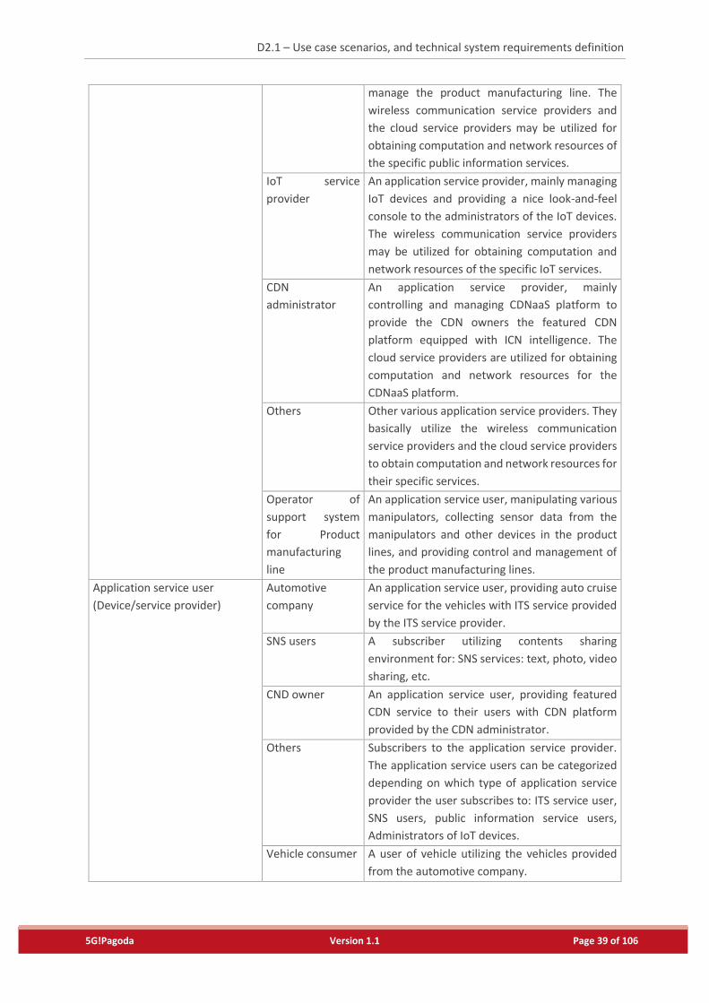
D2.1 – Use case scenarios, and technical system requirements definition
5G!Pagoda Version 1.1 Page 39 of 106
manage the product manufacturing line. The
wireless communication service providers and
the cloud service providers may be utilized for
obtaining computation and network resources of
the specific public information services.
IoT service
provider
An application service provider, mainly managing
IoT devices and providing a nice look-and-feel
console to the administrators of the IoT devices.
The wireless communication service providers
may be utilized for obtaining computation and
network resources of the specific IoT services.
CDN
administrator
An application service provider, mainly
controlling and managing CDNaaS platform to
provide the CDN owners the featured CDN
platform equipped with ICN intelligence. The
cloud service providers are utilized for obtaining
computation and network resources for the
CDNaaS platform.
Others Other various application service providers. They
basically utilize the wireless communication
service providers and the cloud service providers
to obtain computation and network resources for
their specific services.
Operator of
support system
for Product
manufacturing
line
An application service user, manipulating various
manipulators, collecting sensor data from the
manipulators and other devices in the product
lines, and providing control and management of
the product manufacturing lines.
Application service user
(Device/service provider)
Automotive
company
An application service user, providing auto cruise
service for the vehicles with ITS service provided
by the ITS service provider.
SNS users A subscriber utilizing contents sharing
environment for: SNS services: text, photo, video
sharing, etc.
CND owner An application service user, providing featured
CDN service to their users with CDN platform
provided by the CDN administrator.
Others Subscribers to the application service provider.
The application service users can be categorized
depending on which type of application service
provider the user subscribes to: ITS service user,
SNS users, public information service users,
Administrators of IoT devices.
Vehicle consumer A user of vehicle utilizing the vehicles provided
from the automotive company.
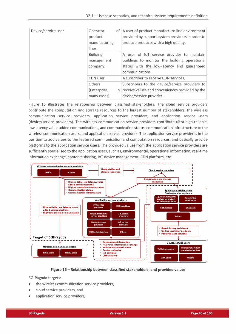
D2.1 – Use case scenarios, and technical system requirements definition
5G!Pagoda Version 1.1 Page 40 of 106
Device/service user Operator of
product
manufacturing
lines
A user of product manufacture line environment
provided by support system providers in order to
produce products with a high quality.
Building
management
company
A user of IoT service provider to maintain
buildings to monitor the building operational
status with the low-latency and guaranteed
communications.
CDN user A subscriber to receive CDN services.
Others
(Enterprise, in
many cases)
Subscribers to the device/service providers to
receive values and conveniences provided by the
device/service provider.
Figure 16 illustrates the relationship between classified stakeholders. The cloud service providers
contribute the computation and storage resources to the largest number of stakeholders: the wireless
communication service providers, application service providers, and application service users
(device/service providers). The wireless communication service providers contribute ultra-high-reliable,
low latency value-added communications, and communication status, communication infrastructure to the
wireless communication users, and application service providers. The application service provider is in the
position to add values to the featured communication and computation resources, and basically provide
platforms to the application service users. The provided values from the application service providers are
sufficiently specialised to the application users, such as, environmental, operational information, real-time
information exchange, contents sharing, IoT device management, CDN platform, etc.
Figure 16 – Relationship between classified stakeholders, and provided values
5G!Pagoda targets:
the wireless communication service providers,
cloud service providers, and
application service providers,
Cloud service providersM NOs M VNOs
W ireless com m un ication service providersCom putation and storage resources
M NO users M VNO users
W ireless com m un ication usersVeh icle consum er
Operator of p roduct m anufacturing lines
CDN users Others
Device/service users
• U ltra reliab le, low latency, va lue added com m un ications
• H igh-rate m ob ile com m un ication
Operator of support system for p roduct m anufacturing lines
Autom otive com pan ies
CDN ow ners SNS users
Others
App lication service usersDevice/service providers
ITS service providers
SNS providers
Pub lic in form ation service providers
ITS service providers
Support system providers
IoT service providers
CDN adm in istrators Others
App lication service providers
Com putation and storage resources• U ltra reliab le, low latency, va lue
added com m un ications• H igh-rate m ob ile com m un ication• Com m un ication status• Com m un ication in frastructure
• Environm ent in form ation• Real-tim e in form ation exchange• Various operational status• Contents sharing• IoT services• CDN p latform
• Sm art driving assistance• Un ified-quality of products• Featured CDN services
Target of 5G!Pagoda
D2.1 – Use case scenarios, and technical system requirements definition
5G!Pagoda Version 1.1 Page 41 of 106
and provides a single solution which allows these providers to efficiently implement their systems providing
individual values to their customers.
As depicted in Figure 16, each stakeholder plays multiple roles of specific stakeholders. This implies that a
stakeholder serves for various customer stakeholders, and which forces the stakeholders to accommodate
multiple systems in their infrastructure for their customers. Although the current 4G system can multiplex
wireless communication customers, the upcoming 5G system expected to includes provisioning
computation and storage resources besides the wireless communications to application service providers.
Additionally, the wireless communication service providers conduct this with the resources from the cloud
service providers.
We presume that 5G systems expand such a value-chain system, and therefore, an interwork between
systems from the individual stakeholders and its extensibility must be important. Section 4 clarifies
technical requirements including the interwork extensibility.
3.4. Capabilities Expected in 5G System
3.4.1. Use case 1: Smart Drive-Assistant Services
In order to realize uRLLC in multiple stakeholder policies, 5G system needs to cover wide areas anywhere
the vehicle travels, and to simultaneously make communication transactions (signal processing to maintain
the communication links for the vehicles and entities for the drive-assistance) promptly treated every time
when the communications occur. This implies that the anticipated capabilities for the service provisioning
and network management for the 5G system are:
1-1) [Low latency] The 5G system is anticipated to reduce communication transaction latency much less
than the 4G systems in the wide area (the entire 5G system service areas).
1-2) [Robust communication] The 5G system is anticipated to have an ability that communication
robustness should be extremely high compared to the 4G systems even for the mobile devices at
middle range of their speed (0-150km/h).
1-3) [multiple throughput guarantee] The 5G system is anticipated to have an ability to provide multiple
logical communication path for each mobile terminals or devices, with guaranteed throughputs.
3.4.2. Use case 2: Industrial Factory Management
In order to realize wireless communication environment in the factory equipping product manufacturing
lines, 5G system needs to provide the low-latency communications for the interaction between the
manipulators and local controllers, and to simultaneously accommodate a large number of sensor devices
attached to manipulators, local controllers, people working in the factories, communication devices
between the local and central controllers. These anticipate the 5G system with the following capabilities:
2-1) [High connection density] The 5G system is anticipated to have an ability to accommodate a large
number of devices, likely 5,000 or more devices collecting sensing data from manipulators and
controllers, in a single cell.
2-2) [Large variation of communication volume] The 5G system is anticipated to have an ability to collect
sensing data of the various devices in a short period on time, likely data of 10,000 and more devices
in a second, and to be tolerant to the large variation of the communication volume.
D2.1 – Use case scenarios, and technical system requirements definition
5G!Pagoda Version 1.1 Page 42 of 106
2-3) [multiple throughput guarantee] The 5G system is anticipated to guarantee the communication
throughput between manipulators and local controllers, and between local and central controllers in
the communication of sensing data collections, which is same as 1-3).
2-4) [High throughput (bi-direction)] The 5G system is anticipated to provide sufficient computation
power to allow a large volume of communications between the local and central controllers to be
secured.
2-5) [Service workload isolation] The 5G system is anticipated to isolate the communications of each pair
of manipulators and controllers to localize the communication failures of the manipulators and
controllers.
2-6) [Low latency] The 5G system is anticipated to have an ability that the communication transaction
between the manipulators and local controllers is shortened compared to the 4G systems, likely some
milliseconds, which is same as 1-1).
3.4.3. Use case 3: Ensuring QoS on demands
To ensure QoS on demand as per use case 3, the 5G system should support the following:
3-1) [High connection density] The 5G system is anticipated to have an ability to accommodate a large
number of mobile terminals, likely 400 – 1,000 or more mobile terminals with the different throughput
requirements, which is same as 2-1).
3-2) [High throughput uplink direction] The 5G system is anticipated to have an ability to carry a large
volume of communications in a different connection density.
3-3) [Group mobility] The 5G system is anticipated to have ability 3-2) for a group of people (e.g., on board
train) with the middle-range of speed (20-100km/h).
3.4.4. Use case 4: Smart/Virtual Offices
Priority data in an ultra-reliable and low-latency would be the key challenges for security alarm services of
the working place. A few separate channels would be used for different actions for the alarm services.
Capacity demands would be the major challenge for video conferencing. Users within the offices will be
mostly stationary or move slowly, thus, local mobility will not be a critical issue. However, it will be a key
requirement for remote workers who need to access their local resources remotely through highly secured
channels while traveling, or to attend video conferencing on the move. For the smart environment services,
sensed data from diverse sensors would be collected in a different manner: some are time-critical, some
are delay tolerant, some need more reliable communication, etc. Thus, to realize smart/virtual office
service, different slice mechanisms for the different characters of the communications will give benefits.
4-1) [High throughput (bi-direction)] The 5G system is anticipated to have an ability to provide ultra-high
bandwidth regarding both direction of communications, likely up to 1 Gbps and 500 Mbps for
downlinks and uplinks, respectively, which is same as 2-4).
4-2) [High connection density] The 5G system is anticipated to have an ability to provide handle high
connection density, like 75,000 /km2, which is same as 2-1).
4-3) [High processing] The 5G system is anticipated to have an ability to sufficient computational power
to make the high-throughput communications secured.
D2.1 – Use case scenarios, and technical system requirements definition
5G!Pagoda Version 1.1 Page 43 of 106
4-4) [High reliable and low-latency] The 5G system is anticipated to have an ability that the communication
transaction between IoT service provider (smart office service provider) and building management
companies is shortened compared to the 4G systems, likely some milliseconds, which is the same as
combination of 1-1) and 1-2).
4-5) [Large variation of communication volume] The 5G system is anticipated to have an ability to collect
sensing data of the various devices in a short period in a large building, and to be tolerant to the large
variation of the communication volume, which is the same as 2-2).
4-6) [Network segmentation with high security] The 5G system is anticipated to have an ability to provide
on-the-fly highly secured environment for remote access to the local resources.
4-7) [Platform/system compliance] The 5G system is anticipated to have an ability to adapt to the specific
requirements coming from the IoT, including their platforms and control and monitoring systems.
Note that it seems that some smart office services may not strictly require 5G systems, as it may be
possible to implement them with current technologies by increasing physical resources. Nevertheless, 5G
systems should be able to increase their efficiency and to enhance the provided service quality. For
example, cloud-assist RAN (C-RAN) helps to reduce the latency on radio access parts, the NFV technology
would help operators to reduce complexity and cost, and network slicing would provide higher security
and privacy for office-like application, and so forth.
3.4.5. Use case 5: Content Delivery Network as a Service
To realize the CDNaaS platform as per use case 5, the 5G system needs to ensure the following:
5-1) [High throughput (bi-direction)] The 5G system is anticipated to have an ability to provide ultra-high
throughput, up to 1 Gbit/s for a single stream, which is the same as 2-4);
5-2) [Computation and network resource isolation] The 5G system is anticipated to have an ability to
isolate the computation and network resource among the CDN platforms;
5-3) [Flexible Architecture] The 5G system is anticipated to have an ability to give CDN owners choices to
locate functions composing CDN platform. isolate the computation and network resource among the
CDN platforms; and
5-4) [Capacity Elasticity] The 5G system is anticipated to have an ability of capacity elasticity for each
function composing the 5G system; and
5-5) [Platform/system compliance] The 5G system is anticipated to have an ability to provide the single
view of the implementation environment where the CDN platform runs.
Future CDN services will obviously improve video resolution when the wireless communication users obtain
sufficient throughput. The CDNaaS platform will control and manage the CDN functions composing the
CDN platform by appropriately locating the function entities, controlling their capacities depending on the
CDN users’ locations and requests. This control and management includes the topological location of the
functional entities, and capacity meeting the elastic changes of the service demands, and types (ability) of
the mobile terminal belonging to the CDN users. For the sake of dynamic resource control, the CDNaaS
platform has an ability to obtain computation and storage resources from multiple cloud service providers,
and switch the provided computation storage resources, depending on CDN owner strategy to operate
their platform, such as, in a cost-effectively manner, in accordance with the cost, residual capacity, and
response performance of computation and storage resources in order to meet demand changes.
D2.1 – Use case scenarios, and technical system requirements definition
5G!Pagoda Version 1.1 Page 44 of 106
3.4.6. Use case 6: Advancement of Medical Services
To realize the advancement of medical services as per use case 6, the 5G system needs to ensure the
following:
6-1) [Large accommodation] The 5G system is anticipated to have a large capacity, like one billion
subscribers in a mobile operator;
6-2) [High throughput (bi-direction)] The 5G system is anticipated to have an ability to provide ultra-high
throughput, up to 1 Gbit/s for a single stream, which is the same as 2-4); and
6-3) [Low latency] The 5G system is anticipated to have an ability that the communication transaction
between the sensors and manipulators is shortened compared to the 4G systems, likely 1-5
milliseconds, which is same as 1-1)
6-4) [Network segmentation with high security] The 5G system is anticipated to have an ability to provide
on-the-fly highly secured environment for remote access to the local resources, which is same as 4-6).
Advancement of the medical services emerges to employ vital sensors to various things which people use,
such as furniture, consumer electronics, and accessories. The imply the wireless communication service
providers accommodate sensors and smartphones several to ten times larger than 4G systems. This implies
that the wireless communication, cloud, and application service providers maintain communication and
processing sessions, whereas these sensors intermittently make communications.
In a remote surgery scene, the video image will further be important. As described in Section 3.2.7, The
remote surgery will need support system revising every step in the surgery operation with video image
through the surgeon’s operation where the extremely high-resolution video camera and surgery support
system are connected via the wireless communications. Additionally, it demands the low-latency
communications.
All devices in the surgery room and the remote surgeon console require high security and which is the
isolated communication environment from the public communications. The network should be dedicated,
and their communication quality should be kept.
3.4.7. Use case 7: Massive IoT
For realizing the massive IoT use case considering a multi-domain, heterogeneous infrastructure
environment, a set of advanced dedicated core networks have to be deployed, starting with a very light-
weight one in terms of connectivity costs per device (especially for the device, but also for the network)
and increasing towards more security, reliability, mobility and resource reservations.
To address the specific use cases, as previously described, multiple dedicated core networks have to be
deployed in parallel (in the same of different slices) to handle efficiently the specific communication needs.
This includes a careful analysis on grouping of the use cases towards a more efficient network (i.e. two use
cases using the same virtual network infrastructure may perform better than using separate optimized
virtual network infrastructures).
And to provide IoT service efficiently, the 5G system is anticipated to provide the following capabilities as
well:
7-1) [Ultra-reliable connectivity] The 5G system is anticipated to provide ultra-reliable connectivity
between IoT devices and IoT service providers, which is the same as 1-2).
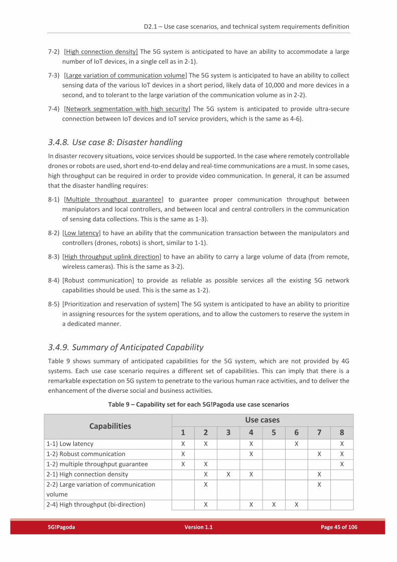
D2.1 – Use case scenarios, and technical system requirements definition
5G!Pagoda Version 1.1 Page 45 of 106
7-2) [High connection density] The 5G system is anticipated to have an ability to accommodate a large
number of IoT devices, in a single cell as in 2-1).
7-3) [Large variation of communication volume] The 5G system is anticipated to have an ability to collect
sensing data of the various IoT devices in a short period, likely data of 10,000 and more devices in a
second, and to tolerant to the large variation of the communication volume as in 2-2).
7-4) [Network segmentation with high security] The 5G system is anticipated to provide ultra-secure
connection between IoT devices and IoT service providers, which is the same as 4-6).
3.4.8. Use case 8: Disaster handling
In disaster recovery situations, voice services should be supported. In the case where remotely controllable
drones or robots are used, short end-to-end delay and real-time communications are a must. In some cases,
high throughput can be required in order to provide video communication. In general, it can be assumed
that the disaster handling requires:
8-1) [Multiple throughput guarantee] to guarantee proper communication throughput between
manipulators and local controllers, and between local and central controllers in the communication
of sensing data collections. This is the same as 1-3).
8-2) [Low latency] to have an ability that the communication transaction between the manipulators and
controllers (drones, robots) is short, similar to 1-1).
8-3) [High throughput uplink direction] to have an ability to carry a large volume of data (from remote,
wireless cameras). This is the same as 3-2).
8-4) [Robust communication] to provide as reliable as possible services all the existing 5G network
capabilities should be used. This is the same as 1-2).
8-5) [Prioritization and reservation of system] The 5G system is anticipated to have an ability to prioritize
in assigning resources for the system operations, and to allow the customers to reserve the system in
a dedicated manner.
3.4.9. Summary of Anticipated Capability
Table 9 shows summary of anticipated capabilities for the 5G system, which are not provided by 4G
systems. Each use case scenario requires a different set of capabilities. This can imply that there is a
remarkable expectation on 5G system to penetrate to the various human race activities, and to deliver the
enhancement of the diverse social and business activities.
Table 9 – Capability set for each 5G!Pagoda use case scenarios
Capabilities Use cases
1 2 3 4 5 6 7 8
1-1) Low latency X X X X X
1-2) Robust communication X X X X
1-2) multiple throughput guarantee X X X
2-1) High connection density X X X X
2-2) Large variation of communication
volume
X X
2-4) High throughput (bi-direction) X X X X
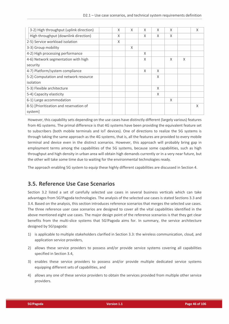
D2.1 – Use case scenarios, and technical system requirements definition
5G!Pagoda Version 1.1 Page 46 of 106
3-2) High throughput (uplink direction) X X X X X X
High throughput (downlink direction) X X X X
2-5) Service workload isolation X
3-3) Group mobility X
4-2) High processing performance X
4-6) Network segmentation with high
security
X X X
4-7) Platform/system compliance X X
5-2) Computation and network resource
isolation
X
5-3) Flexible architecture X
5-4) Capacity elasticity X
6-1) Large accommodation X
8-5) [Prioritization and reservation of
system]
X
However, this capability sets depending on the use cases have distinctly different (largely various) features
from 4G systems. The primal difference is that 4G systems have been providing the equivalent feature set
to subscribers (both mobile terminals and IoT devices). One of directions to realize the 5G systems is
through taking the same approach as the 4G systems, that is, all the features are provided to every mobile
terminal and device even in the distinct scenarios. However, this approach will probably bring gap in
employment terms among the capabilities of the 5G systems, because some capabilities, such as high
throughput and high density in urban area will obtain high demands currently or in a very near future, but
the other will take some time due to waiting for the environmental technologies ready.
The approach enabling 5G system to equip these highly different capabilities are discussed in Section 4.
3.5. Reference Use Case Scenarios
Section 3.2 listed a set of carefully selected use cases in several business verticals which can take
advantages from 5G!Pagoda technologies. The analysis of the selected use cases is stated Sections 3.3 and
3.4. Based on the analysis, this section introduces reference scenarios that merges the selected use cases.
The three reference user case scenarios are designed to cover all the vital capabilities identified in the
above mentioned eight use cases. The major design point of the reference scenarios is that they get clear
benefits from the multi-slice systems that 5G!Pagoda aims for. In summary, the service architecture
designed by 5G!pagoda:
1) is applicable to multiple stakeholders clarified in Section 3.3: the wireless communication, cloud, and
application service providers,
2) allows these service providers to possess and/or provide service systems covering all capabilities
specified in Section 3.4,
3) enables these service providers to possess and/or provide multiple dedicated service systems
equipping different sets of capabilities, and
4) allows any one of these service providers to obtain the services provided from multiple other service
providers.
D2.1 – Use case scenarios, and technical system requirements definition
5G!Pagoda Version 1.1 Page 47 of 106
3.5.1. Reference 1: Reference Use Case Scenario of Remote Monitoring in Industrial Domain (use cases 2, 7, and 8)
Bob is a manager of the quality control division in EJ Co., a broadcasting device manufacturing company
located in Tokyo. One year ago, the company has opened a new factory in Berlin in order to cover European
markets.
Bob is now in charge of the overall quality control of the production and the processes of both places. In
the beginning, the information exchanges between the two different factories and between the
headquarters and the factories needed a lot of human interaction and uneasy to make a real-time
monitoring. The IoT data collected from a local factory was monitored and maintained only in the local
place due to the huge amount of the raw data. Thus, Bob and his team together with production
management team in Tokyo often travelled to Berlin during the system set-up and test phase. After they
set up the same factory automation system with Tokyo factory, processed data related to QoS / QoI have
been collected for a certain period and was regularly delivered to Bob’s team in Tokyo, while other key
processed data related to production management have been delivered to the production management
team in Tokyo. When there were problems, Tokyo office received a collected data on demands. Sometimes,
they wanted to have raw data for detail analysis. The Tokyo team ran the data into the automation control
management program and sometimes compared to Tokyo data, which naturally takes some time until the
analysis has been done.
The company wanted to improve this situation, and wished to monitor and maintain the key data from
both factories in a centric control place in real-time. When it is possible to run the automation control
system with data from both factories, it could give real-time analysis data for consistent QoS / QoI control
for the two distinct locations and prompt trouble-shooting and decision-making. Not only improving the
efficiency of work from the headquarters, it would also avoid having two duplicate human resources and
systems in the two locations for the same analysis.
Last month, the company started to use a secured industrial monitoring solution from Pagoda Systems Inc.,
one of the frontrunners of the 5G service providers. Pagoda Systems Inc. is providing a total solution that
connects cloud providers and 5G network providers with secured channels for the credential industry data.
Under the Pagoda Systems’ solution, each factory site has local gateways that are connected to a cloud
system collaborating with local 5G network providers. The gateway is performing preliminary analysis of
the raw data and transfers meaningful data to the headquarters in Tokyo though its secure channel in the
cloud. The headquarters is also connected to its local cloud provider with its local 5G network provider.
Bob is now able to monitor the QoS / QoI data from the two distinct sites in real-time with user-friendly
GUI provided by the Pagoda Systems’ secured industrial monitoring solution.
When he came to work in the morning, he found a message from the monitoring system that abnormal
data was detected for about 10 min. in the last evening in Berlin, but it returned back to normal after that.
As it may become bigger problem later, Bob wanted to have all related data for deeper analysis. Bob
requested Pagoda Systems Inc. to open a separate short-term service channel for the diagnosis so that the
quality of the regular data handling is not deteriorated. The stored data around the problem time is
analysed in a separate high-secured channel in a different virtual machine from the regular data analysis
machine.
Technically, Pagoda Systems Inc. runs its services via its own orchestrator solution that manages service
level of multi-domain slices collaborating with different cloud service providers and different 5G network
providers. It allocates an additional slice in order to provide such on-demand service extension in a short-
term base. Considering the character of the application data, Pagoda Systems Inc. particularly provides
D2.1 – Use case scenarios, and technical system requirements definition
5G!Pagoda Version 1.1 Page 48 of 106
strong security controllers to its customers. After the trouble-shooting, the on-demand channel is closed
and the regular monitoring system to connect the two sites is running.
3.5.2. Reference 2: Reference Use Case Scenario of Tourism Support (use cases 3 and 5)
During the 2020 Tokyo Olympics, a basketball match is scheduled between the teams of Germany and
Japan. A large number of German tourists came to cheer up the German national team. Before the start of
the game, the German tourists, fascinated by the atmosphere, the stadium, the Japanese people around
them cheering up their Japanese national team, started taking photos and videos, and posting them on
their PAGODA SNS accounts. Some German tourists started HD live streams of the event to their PAGODA
SNS accounts. Being in Japan, most of the content generated by the German tourists go to local caches of
PAGODA SNS Inc. in Japan. PAGODA SNS Inc. notices the amount of content stored in its local caches in
Japan, that are later accessed by friends and relatives of the German tourists being in Germany. PAGODA
SNS Inc. then requests Pagoda CDN-Slicing Inc. to create a CDN slice consisting of ICN-enabled caches
placed in Germany connecting through specific VPNs with dedicated bandwidth to the PAGODA SNS Inc.’s
local caches in Japan. The content generated by German tourists is aggregated at the local caches in Japan,
and then forwarded in bulk to CDN caches in Germany. Friends and relatives of German tourists can then
access and view their generated content from nearby caches, enjoying better quality of experience.
3.5.3. Reference 3: Reference Use Case Scenario of Office Roaming (use cases 3,4 and 5)
Alice has just arrived at Tokyo at the day before Tokyo Olympic opens in order to report series of live events
and news on Tokyo Olympic to viewers of ‘Europe Social Online ESO’ where she works for. The day before
she arrived, she was, at ESO head office, requested to visit Tokyo to work as a tentative remote office
providing reports on the Olympic events while Tokyo Olympic was held (for two weeks). It was an
unexpected request from her boss, because a preliminarily planned reporter (Bob) was immediately
changed to the investigation of terrorism occurred in multiple places in Europe because he was an expert
on terrorism reports in ESO. At that day, Alice accepted the request without any perplexity, jumped on an
aircraft.
Alice missions are delivering live Olympic news on and editing of competition results of European athletes,
their preparation before competition/games, investigational reports on games in Olympic, and local people
(Japanese) activities for Olympic. The raw materials of contents are provided by NHK (Japanese national
broadcast) that Bob preliminarily won its contract. The provided materials are huge in amount, she needs
first to edit from them, and upload report contents to ESO head office contents repository.
Because of the sudden member change, Alice rushed to prepare everything in a single day. Just after she
left airport in Tokyo, she started the preparation: first found the tentative office, and second prepared
content editing environment including secure communications to ESO head office and NHK contents
repository. The found office equipped regular office furniture. A printer, projector set, and video cameras
were provided by a rental company could be delivered at that day. The electric appliances could utilize
cellular communications. The generic electric appliances in this era (in 2020) were expected to be capable
of high-throughput communications via cellular networks. Therefore, the electric appliance that Alice
rented could deal with a large size and number of contents in a manner establishing secure associations to
ESO head office as tentative belongings. Her laptop computer, where she would do almost all operations,
worked as a remote-desktop. Although the current 4G systems suffered from a long delay in the remote
D2.1 – Use case scenarios, and technical system requirements definition
5G!Pagoda Version 1.1 Page 49 of 106
desktop use, the upcoming 5G systems allowed servers of remote desktop to be stuck out near her office,
and resulted in minimizing the communication delay. And in an escalating manner, several servers for
content editing, electric appliance associations, and content sharing from NHK were also stuck out near
her office. They were logically controlled by ESO head office or NHK, however, the physical communications
were all conducted in Tokyo! To make the controls secured, the network and server’s computation
resources were isolated from the other users renting the same office as Alice did.
From perspective of the communication technology, the wireless communication, cloud, and application
service providers need to have solutions to collaborate establishing Alice’s remote office environment. The
(local) wireless communication service provider provides high-throughput and isolated wireless
communication to Alice’s laptop computer, and the electric appliances. Additionally, they construct the
edge site computation and network environments all together. The actual application-level services, i.e.,
editing tools, electric appliance association establishment, and secure communication management, are
provided by multiple application service providers. Further, each of them obtains resources from the local
cloud service providers. It shall be noted that the application service providers are not limited at only local
(Tokyo) due to the other service physical providers provide network and computation resources at Tokyo.
The wireless communication service provider also obtains the computation resources for controlling and
managing communications for laptop computers and electric appliances (management entities and
gateways) collaboratively from the cloud service providers, at the edge site. And the cloud service provider
also can improve convenience to the application service providers by locating computation resource at the
same topological location for the servers stuck out from the EOS head office, electrical appliances, and
security controller for NHK.
The next day at tentative office, Alice was in the middle of high tense to provide a live video stream of
Olympic opening ceremony. She continuously switched multiple materials fed from NHK by comparing
them every second. In the early morning of the opening day, the communication quality had been
deteriorated. Many news business operators started to feed live video streams. Alice also reported that
her communication status is due to the contract with the application service providers. She immediately
discussed with ESO head office, and made re-contracted with the application service provider to upgrade
the communication and computation service level. Thus, the multiple video streams are stably fed from
NHK, and Alice could now concentrate to the video material selections.
Although the live video stream was mainly uploaded to ESO head office, there were also many ESO viewers
at Tokyo Olympic stadium. They watched the live video streams as simultaneously cheering the ceremony
at audience seats. Logically, the ESO viewers in the stadium obtained the live video streams from ESO head
office, but physical delivery took a shortest path from Alice office and the stadium. The video stream
delivery at this moment, utilized CDN. The CDN platform was also tentatively constructed by the CDNaaS
provider ordered by ESO head office. This optimal content delivery was also conducted at Europe. Although
the content repository is at the ESO head office, a huge number of ESO viewers reside all over Europe.
Therefore, CDN fed the vide stream to the viewer before the video contents arrived at the ESO head office
to improve viewers’ QoE.
From perspective of the communication technology, again, the ESO employed multiple wireless
communication and cloud service providers. The video stream viewers subscribed different wireless
communication service providers. CDN platform obtain computation resources for converting video in
accordance with display resolutions of view’s mobile terminals. The wireless communication service
providers also employed different cloud service providers, and CDNaaS platformer prepare their content
delivery components over these cloud service providers.
D2.1 – Use case scenarios, and technical system requirements definition
5G!Pagoda Version 1.1 Page 50 of 106
In the ESO cases, the cloud service providers provide computation resource to both the wireless
communication and application service providers. The management for resource assignment over multiple
users. Additionally, wireless communication and cloud service providers are expected to arrange the
location of communication and computation resources, respectively, for multiple application service
providers to make all the communications of Alice remote office to have the minimum communication
delay.
It is important for many office users to have secure communication and processing environments including
the communication and processing stability. The application service providers are expected to provide
isolated communication environment. Additionally, the wireless communication and cloud service
providers are expected to attach multiple isolated communication environments provided by multiple
application service providers together in order to meet ESO remote office use. As Alice made re-contracted,
the application service providers are also expected to support the on-demand QoS. And it shall be noted
that the communication status should be accurately and clearly notified to the users.
D2.1 – Use case scenarios, and technical system requirements definition
5G!Pagoda Version 1.1 Page 51 of 106
4. Analysis of Reference Scenarios and Technical
Requirements
The use cases and stakeholders, discussed in Sections 3.2 and 3.3 respectively, clarified that 5G!Pagoda
targets multiple stakeholders. The final goal of 5G!Pagoda is to develop a unique architecture that can be
adopted by these multiple stakeholders. 5G!Pagoda partners premise that the unique architecture can
smoothly contribute to stakeholders providing value-added mobile communication services in initiating
and developing their business.
As discussed in section 3.4.9, 5G system is expected to provide various capability sets depending on the
use case. To this end, this section takes three steps in analysing each of the capabilities to be taken in the
5G system:
First, analysing whether 5G system can take the 4G system approach, that is, all the users (mobile
terminals and IoT devices) have the equivalent capabilities, resulting that 5G system needs more
sophisticated approach, that is, the capability-on-demand;
Second, more deeply analysing what can be issues in order to take the capability-on-demand to the 5G
systems in terms of operation circumstance; and
Third, deriving the technical requirements from the analysed issues in the second step.
Following subsections derives the technical requirements through these steps in terms of the individual
service provider’s viewpoints.
4.1. Capabilities difficult to provide/realize to all the users
First, a question on the capabilities is whether or not each stakeholder employs all the capabilities for all
the users, as the 4G system does. The following capabilities are hard to be implemented for all the users.
Low latency communication
Prioritization and reservation of system
Regarding the capability of low latency, the wireless communication service providers are required to
fundamentally equip the computation and storage resources at base stations and/or nodes in radio access
network (edge entities). The computation resources are assigned to control and manage the
communication links of the mobile terminals and IoT devices. Therefore, the following requirement has
been identified:
R- 1: the 5G systems equip computational resources at their edge entities.
In terms of the application service providers, because they are provided the communication service from
the wireless communication service providers, the application service providers are also required to
provide the application service processes (software execution) at the edge entities in the wireless
communication service providers. Additionally, because the wireless communication service and
application service providers, in some cases, obtain computational resources from the cloud service
providers, the cloud service providers also provide the computation resources to the edge entities.
Therefore, the following requirement has been identified:
D2.1 – Use case scenarios, and technical system requirements definition
5G!Pagoda Version 1.1 Page 52 of 106
R- 2: the wireless communication providers and application service providers have an interwork
solution to run the service processing provided from the application service providers with low
latency communications;
R- 3: it is required that the wireless communication service providers and application service providers
have an interwork solution in the resource management to the cloud service providers to obtain
the computation resources.
Regarding the prioritization and reservation of system, the wireless communication, cloud, and
application services providers (called “service providers” hereafter) should be able to prioritize the users
and services to correspond to the disasters which damage a portion of their system, and utilize the
available (non-damaged) resources to be the higher prioritized users and services. This implies that the
service providers should have an ability to reorganize the service system over the available resources. In
other words, to improve resource flexibility, the remaining portion of hardware resources in the service
providers should be diverted to the high priority service systems. Therefore, the following requirement
has been identified:
R- 4 : the service providers have two types of stratums, that is, physical resource layers where various
service systems (implemented by software) can run, and software layer which control and
manage the services system.
Additionally, because it is difficult to predict which region the disaster damages, the software layer of the
service systems with high priority be re-located to the non-damaged regions. Therefore, the following
requirement has been identified:
R- 5 : the system implemented in software layer can be relocated on physical resource layers
developed across the business regions on demand.
4.2. Capability on Demand (Service Provisioning Dynamics)
Second, a question on the capabilities is whether stakeholders can dynamically utilize the capabilities
(called capability-on-demand, hereafter) or not. The ‘capability-on-demand’ is defined as that a user or a
group of users can pick up the capability when they start services, or can change the capability while the
service is being provided. Therefore, the following requirement has been identified:
R- 6 : the 5G system manage maps between users and capabilities belonging to the users;
R- 7 : the 5G system track the user subscription to the required capabilities in any time instance.
In the case to replacing capacity set or their portion, system components realizing a capability are different
among capabilities. Therefore, the following requirement has been identified:
R- 8 : the hardware resources assigned to a system component (software) be updated (added, removed
and replaced) when the capability set gets updated.
This implies that the hardware resources need to be controlled and managed at the implementation
level.
In terms of including requirements R- 4 through R- 7 in the 5G system, the following requirement has been
identified:
R- 9 : the 5G system have a sufficient interwork between controlling and management components in
software and physical resource layers.
D2.1 – Use case scenarios, and technical system requirements definition
5G!Pagoda Version 1.1 Page 53 of 106
This is because the managed user subscriptions are maintained by the functions in the software layer, while
managed service system components realizing capability set are maintained by the physical resource layer
because of R- 8.
4.3. Service Provisioning in Race Condition
In the 5G err, the business stakeholders expand their business and therefore, the same or similar value-
add communication service will be provided by multiple providers. This implies users will have multiple
choices more than the 4G err, and the providers pursue the high quality values (services) and more
convenient touch points from the users. The latter feature is discussed in the next section.
In terms of improving the quality of services, several capabilities listed below are targets:
Robust communication
Multiple throughput guarantee
High throughput
High processing performance
Network segmentation with high security
Capacity elasticity
In order to realize these capabilities with a perspective of aforementioned requirements (R- 1 through R-
9), the system components (software) should primarily have the sufficient capacity.
Robust communication can be break down how much redundancy level can be taken in processing and
communication of provided services. This can also imply how much resources in computation, storage and
communication) are assigned from the physical resource layer. e.g., driving assistances need multiple
prepared wireless and fixed communication links, and computation and storage resources for the
processing in ITS and public information service providers. Although the other use cases have individual
redundant levels, the resources, described in R- 8 and R- 9, and redundancy mechanism must be required.
Therefore, the following requirement has been identified:
R- 10 : the 5G system have the redundancy mechanism meetings the individual redundancy levels
enforced by service providers.
Regarding the multiple throughput guarantee, the 5G system should provide multiple throughput levels
and subscribers can have opportunities to pick up a set of different throughput guarantees. Although he
4G system can currently provide its users such a opportunities, however, the throughput control is limited
in a single wireless communication providers. In the 5G err, the there are multiple stakeholders compose
a provided service. Therefore, the following requirement has been identified:
R- 11 : the 5G system have a mechanism for the end-to-end QoS guarantee in providing a service, that
is, specifically, the multiple stakeholders must be able to interwork with one another from
service provider to end users.
Regarding the high throughput, the 5G system must simply obtain the resources treating the wireless users’
communication. The issue can be that a single wireless communication provider does not equip sufficient
resources in the physical resource layer and capacity in the software layer. In this case the resources should
be flexibly provided from the other service providers (e.g., fixed communication service provider for
communication links, and cloud service providers for processing to control and manage the communication
links. Therefore, requirement R- 9 is needed.
Regarding the high processing performance, requirement R- 9 is also needed.
D2.1 – Use case scenarios, and technical system requirements definition
5G!Pagoda Version 1.1 Page 54 of 106
Regarding the network segmentation with high security, there are two aspects: one is segmenting network
and processing resources, and the other is secure communication environments. Although the 4G system
can isolate the resources (computation, storage, links, and network topology) for individuation service
provisioning, it is realized in a single stakeholder. Therefore, the following requirement has been identified:
R- 12 : all the service system operated by stakeholders can corroboratively isolate resources from top
of specific service provisioning to the users.
The capacity elasticity is not realized by the 4G systems. Especially, MNOs often take a policy to prepare
sufficient resources meeting the peak usage of their communication services. This is because the MNOs
inherently provides all-in-one feature to the wireless communication users, and it includes mobile
telecommunication with high stabilities and communication quality. Even recent MVNOs emerge to limit
communication types (e.g., IoT-device-dedicated communications), and however, they limit the entire
volume of the subscribers’ usage with the total volume limitation enforced at the inter-links between the
MNO and MVNO. The fundamental issue of this is caused by the MNO policy described above.
The reason why the MNO take the peak volume policy is the implemented architecture does not take two-
layer construction (requirements R- 4 and R- 5). This leads to long duration to deal with the dynamic
resource assignment. Although recently MNOs emerge to utilize the NFV in implementing the 4G system,
the on-demand resource assignments still need long duration in controlling resources and VNFs booting
processes. Therefore, the following requirement has been identified:
R- 13 : 5G system rapidly update resource assignment to system components (software) likely to be in a
second or shorter.
This requirement can also include the capability:
Large variation of communication volumes.
4.4. Interwork among Service Providers and among Stakeholders
Currently the most service provisioning forms a direct relationship between stakeholders of service
provider and consumer (business to consumer; B2C). However, this form has begun to transform to service
provider, service provider and consumer (business to business to consumer; B2B2C). All the use cases and
typical use case scenarios, described in Sections 3.2 and 3.5, includes the latter form. We premise that it
will have a large share in the 5G era.
A key of driving B2B2C to be developed is at the application service providers, that is, the second service
provider in B2B2C. In this e-commerce model:
1) the first service provider provides values (computation, storage and communication resources) to the
second service provider;
2) the second service provider (the application service provider) provides a representative value-added
service utilizing wireless communications to their users (consumers) with free-of-charge; and
3) simultaneously, the newly obtained information on and/or controlling consumers’ life activities to be
provided to the third customer for the second service provider.
In this e-commerce ecosystem, it is important that the service systems classified by the different
stakeholder have the sufficient interwork. This implies that the customer stakeholder shall tend to favour
the provider stakeholder accepting various demands. Therefore, the following requirement has been
identified:
D2.1 – Use case scenarios, and technical system requirements definition
5G!Pagoda Version 1.1 Page 55 of 106
R- 14 : the 5G system include various processing realizing customer demands; and
R- 15 : the 5G system make the interwork expanded as the new service provisioning in accordance with
the demand changes.
D2.1 – Use case scenarios, and technical system requirements definition
5G!Pagoda Version 1.1 Page 56 of 106
5. 5G!Pagoda Architecture Model and Concepts
In this section, the initial considerations on the high level architecture for the 5G!Pagoda project are
described.
5.1. General Concepts
5.1.1. Mobile Network Slicing[34]1
It is a well-known fact that the concept of slice in networking has been first introduced in the overlay
network research efforts, such as PlanetLab[21], in 2002. At that time, a slice has been defined as an isolated
set of network bandwidth, computational, storage, resources allocated for a group of users that “program”
network functions and services over their overlay network overlaid across “the planet”. Since various
network virtualization testbed efforts such as PlanetLab EU, PlanetLab JP, GENI, VNode, FLARE[18], Fed4Fire,
have inherited the concept of slices as a basis of the infrastructures, as a set of programmable resources
to tailor new network services and protocols, it is quite natural to use the slice concept to be extended to
mobile networking. Network Slicing is an extension of the concept of “slice” originally defined to mobile
networking with additional focus on mobile network functions implemented on top of programmable
resources.
The terminology “network slicing” has caught much attention in research communities and industries, as
well as standards developing organizations (SDOs) such as 3GPP[29] and ITU[28]. Although the definition of
network slicing is still under heavy discussion, we have generally defined “slice” as an isolated collection of
programmable resources to implement network functions and application services through software
programs to accommodate individual network functions application services within each slice without
interfering with the other functions and services on the other slices[16].
Network slicing is considered one of the most important concepts to realize “extreme flexibility” in 5G
mobile networking[13]. The current mobile networks are optimized to serve only mobile phones. However,
5G mobile networking needs to serve a variety of devices with very different, heterogeneous quality of
service (QoS) requirements without interference among one another. The 5GMF white paper[13] classifies
communications to be enabled in 5G mobile networks into three categories, eMBB (enhanced Mobile
Broad Band), mMTC (massive Machine Type Communications), and URLLC (Ultra Reliable and Low Latency
Communications). Also the 5G infrastructure public private partnership (5G PPP) defines three use cases,
xMBB (massive broad band) to deliver gigabytes of bandwidth to mobile devices on demand, mMTC
(massive Machine Type Communications) also known as massive Internet of Things.
As discussed above, the concept of network slicing has originated from overlay network and network
virtualization research efforts. Although the concept of network slicing for mobile networking is relatively
new in the technology world today, it is rapidly gaining momentum as we proceed into the future.
5GMF network architecture committee, led by some of the authors of this deliverable, has identified the
importance of end-to-end network slicing, all the way from user equipment (UE) to cloud data centres for
1 Note that this subsection is almost entirely quoted from a part of our publication to appear [34].
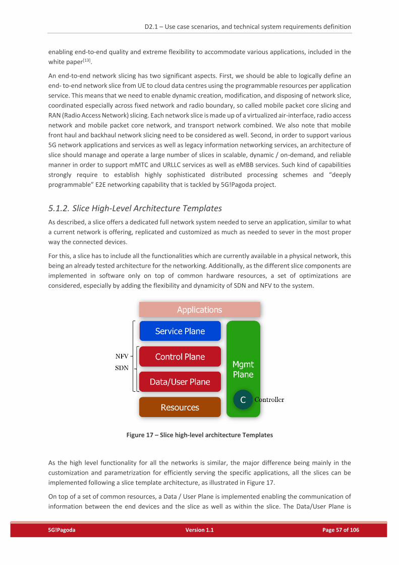
D2.1 – Use case scenarios, and technical system requirements definition
5G!Pagoda Version 1.1 Page 57 of 106
enabling end-to-end quality and extreme flexibility to accommodate various applications, included in the
white paper[13].
An end-to-end network slicing has two significant aspects. First, we should be able to logically define an
end- to-end network slice from UE to cloud data centres using the programmable resources per application
service. This means that we need to enable dynamic creation, modification, and disposing of network slice,
coordinated especially across fixed network and radio boundary, so called mobile packet core slicing and
RAN (Radio Access Network) slicing. Each network slice is made up of a virtualized air-interface, radio access
network and mobile packet core network, and transport network combined. We also note that mobile
front haul and backhaul network slicing need to be considered as well. Second, in order to support various
5G network applications and services as well as legacy information networking services, an architecture of
slice should manage and operate a large number of slices in scalable, dynamic / on-demand, and reliable
manner in order to support mMTC and URLLC services as well as eMBB services. Such kind of capabilities
strongly require to establish highly sophisticated distributed processing schemes and “deeply
programmable” E2E networking capability that is tackled by 5G!Pagoda project.
5.1.2. Slice High-Level Architecture Templates
As described, a slice offers a dedicated full network system needed to serve an application, similar to what
a current network is offering, replicated and customized as much as needed to sever in the most proper
way the connected devices.
For this, a slice has to include all the functionalities which are currently available in a physical network, this
being an already tested architecture for the networking. Additionally, as the different slice components are
implemented in software only on top of common hardware resources, a set of optimizations are
considered, especially by adding the flexibility and dynamicity of SDN and NFV to the system.
Figure 17 – Slice high-level architecture Templates
As the high level functionality for all the networks is similar, the major difference being mainly in the
customization and parametrization for efficiently serving the specific applications, all the slices can be
implemented following a slice template architecture, as illustrated in Figure 17.
On top of a set of common resources, a Data / User Plane is implemented enabling the communication of
information between the end devices and the slice as well as within the slice. The Data/User Plane is
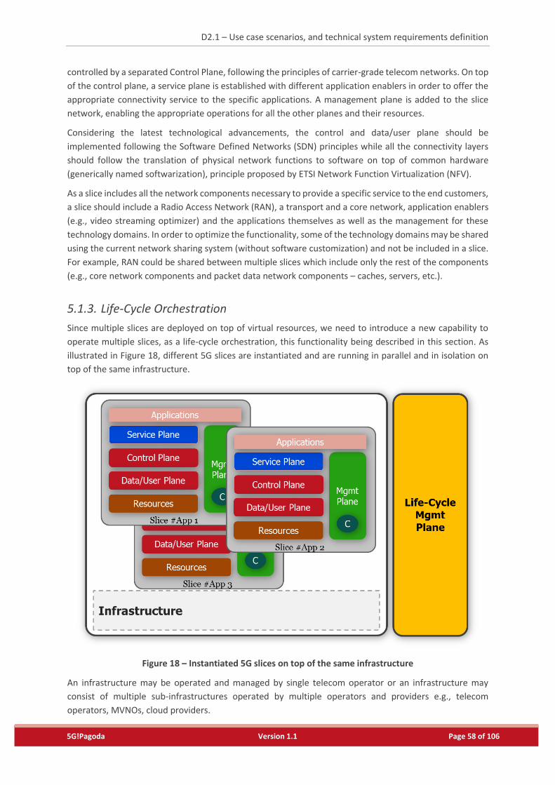
D2.1 – Use case scenarios, and technical system requirements definition
5G!Pagoda Version 1.1 Page 58 of 106
controlled by a separated Control Plane, following the principles of carrier-grade telecom networks. On top
of the control plane, a service plane is established with different application enablers in order to offer the
appropriate connectivity service to the specific applications. A management plane is added to the slice
network, enabling the appropriate operations for all the other planes and their resources.
Considering the latest technological advancements, the control and data/user plane should be
implemented following the Software Defined Networks (SDN) principles while all the connectivity layers
should follow the translation of physical network functions to software on top of common hardware
(generically named softwarization), principle proposed by ETSI Network Function Virtualization (NFV).
As a slice includes all the network components necessary to provide a specific service to the end customers,
a slice should include a Radio Access Network (RAN), a transport and a core network, application enablers
(e.g., video streaming optimizer) and the applications themselves as well as the management for these
technology domains. In order to optimize the functionality, some of the technology domains may be shared
using the current network sharing system (without software customization) and not be included in a slice.
For example, RAN could be shared between multiple slices which include only the rest of the components
(e.g., core network components and packet data network components – caches, servers, etc.).
5.1.3. Life-Cycle Orchestration
Since multiple slices are deployed on top of virtual resources, we need to introduce a new capability to
operate multiple slices, as a life-cycle orchestration, this functionality being described in this section. As
illustrated in Figure 18, different 5G slices are instantiated and are running in parallel and in isolation on
top of the same infrastructure.
Figure 18 – Instantiated 5G slices on top of the same infrastructure
An infrastructure may be operated and managed by single telecom operator or an infrastructure may
consist of multiple sub-infrastructures operated by multiple operators and providers e.g., telecom
operators, MVNOs, cloud providers.
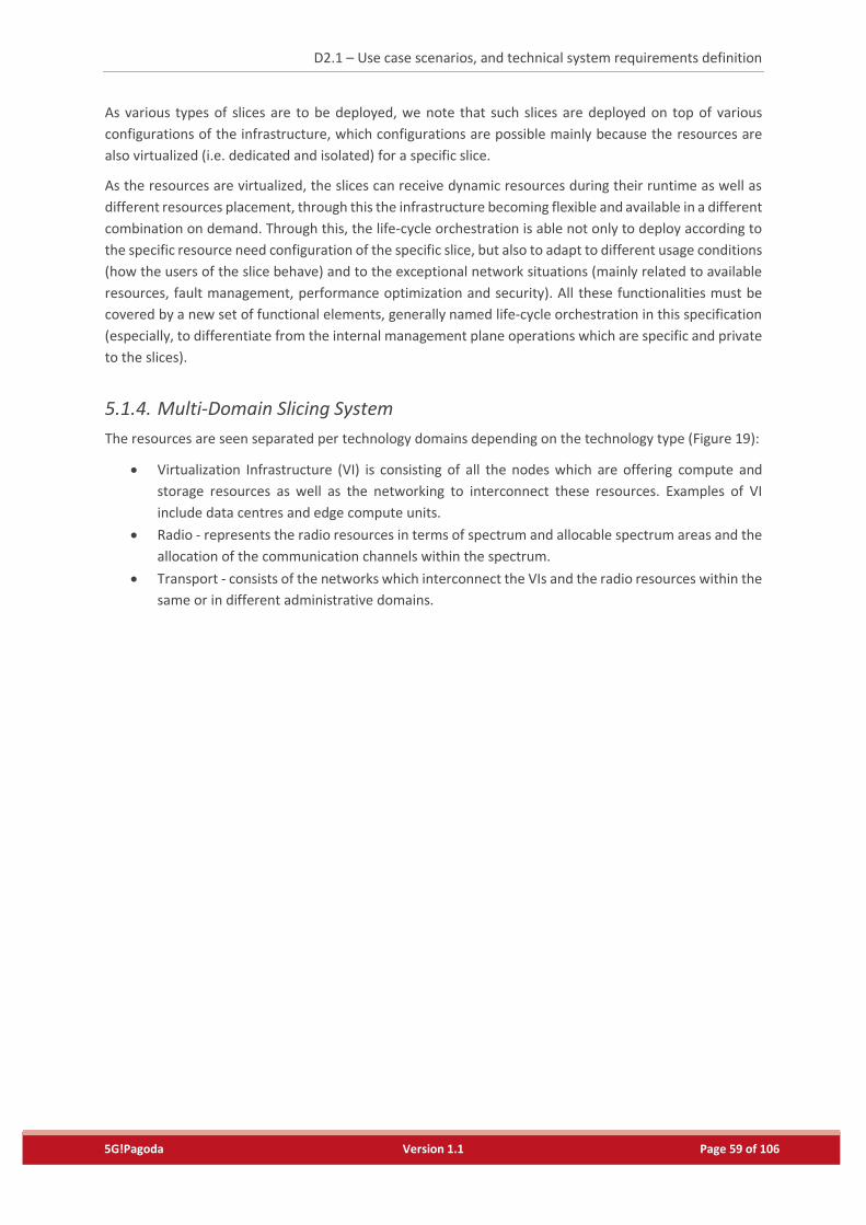
D2.1 – Use case scenarios, and technical system requirements definition
5G!Pagoda Version 1.1 Page 59 of 106
As various types of slices are to be deployed, we note that such slices are deployed on top of various
configurations of the infrastructure, which configurations are possible mainly because the resources are
also virtualized (i.e. dedicated and isolated) for a specific slice.
As the resources are virtualized, the slices can receive dynamic resources during their runtime as well as
different resources placement, through this the infrastructure becoming flexible and available in a different
combination on demand. Through this, the life-cycle orchestration is able not only to deploy according to
the specific resource need configuration of the specific slice, but also to adapt to different usage conditions
(how the users of the slice behave) and to the exceptional network situations (mainly related to available
resources, fault management, performance optimization and security). All these functionalities must be
covered by a new set of functional elements, generally named life-cycle orchestration in this specification
(especially, to differentiate from the internal management plane operations which are specific and private
to the slices).
5.1.4. Multi-Domain Slicing System
The resources are seen separated per technology domains depending on the technology type (Figure 19):
Virtualization Infrastructure (VI) is consisting of all the nodes which are offering compute and
storage resources as well as the networking to interconnect these resources. Examples of VI
include data centres and edge compute units.
Radio - represents the radio resources in terms of spectrum and allocable spectrum areas and the
allocation of the communication channels within the spectrum.
Transport - consists of the networks which interconnect the VIs and the radio resources within the
same or in different administrative domains.
D2.1 – Use case scenarios, and technical system requirements definition
5G!Pagoda Version 1.1 Page 60 of 106
Figure 19 – Life-cycle orchestration for multi-domain architecture
Each of the technology domains has its own Resource Orchestration (RO). This decision was taken because
of the different structures of the resources, which from the perspective of their respective specifications,
should be handled by separate ROs, each specific to a technology domain. It is foreseen that for example,
for the transport network, an SDN WAN controller will act as the RO while for a data centre, a typical VIM
(e.g., OpenStack) from the perspective of ETSI MANO may be used.
To be able to use the resources in an appropriate manner across the administrative domain, an
administrative domain resource orchestrator, named here Aggregation RO, is considered on top of the
technology specific ROs, which aggregates all the resources into the same RO, through this operation,
making the resources transparent to the domain-specific slice orchestrator. This aggregator RO can be seen
as a hierarchical type of resource aggregation, mainly for efficiency reasons of understanding the deployed
system. For example, in Figure 20, an Aggregation RO can be considered for the radio technology domain
across the different technologies and spectrum used.
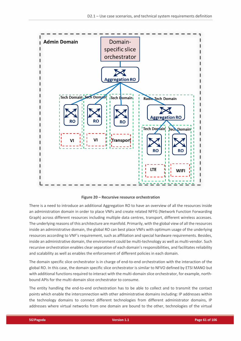
D2.1 – Use case scenarios, and technical system requirements definition
5G!Pagoda Version 1.1 Page 61 of 106
Figure 20 – Recursive resource orchestration
There is a need to introduce an additional Aggregation RO to have an overview of all the resources inside
an administration domain in order to place VNFs and create related NFFG (Network Function Forwarding
Graph) across different resources including multiple data centres, transport, different wireless accesses.
The underlying reasons of this architecture are manifold. Primarily, with the global view of all the resources
inside an administrative domain, the global RO can best place VNFs with optimum usage of the underlying
resources according to VNF’s requirement, such as affiliation and special hardware requirements. Besides,
inside an administrative domain, the environment could be multi-technology as well as multi-vendor. Such
recursive orchestration enables clear separation of each domain’s responsibilities, and facilitates reliability
and scalability as well as enables the enforcement of different policies in each domain.
The domain specific slice orchestrator is in charge of end-to-end orchestration with the interaction of the
global RO. In this case, the domain specific slice orchestrator is similar to NFVO defined by ETSI MANO but
with additional functions required to interact with the multi-domain slice orchestrator, for example, north-
bound APIs for the multi-domain slice orchestrator to consume.
The entity handling the end-to-end orchestration has to be able to collect and to transmit the contact
points which enable the interconnection with other administrative domains including: IP addresses within
the technology domains to connect different technologies from different administrator domains, IP
addresses where virtual networks from one domain are bound to the other, technologies of the virtual
D2.1 – Use case scenarios, and technical system requirements definition
5G!Pagoda Version 1.1 Page 62 of 106
networks binding the two domains and VNF level IP addresses in case the slice network is explicitly settled
across the domains (IP addresses are allocated in the slice based on a common addressing schema which
is done through the orchestration as in the case of any PaaS or SaaS and not for IaaS where only resources
are allocated and the tenant has to create the network through its own administrative means).
To be able to broker and to bind resources within multiple administrative domains, a multi-domain slice
orchestrator is introduced into the system. The multi-domain slice orchestrator is communicating with the
orchestrators in the administrative domains to be able to stitch a slice across the multiple administrative
domains, by using resources allocated in each of them.
A Business Service Slice orchestrator is added in the logical multi-domain management to be able to
interact with the administrator of the slice in the management of the life-cycle operations as well as to
offer the administrative entry points to the software elements from which the slice is composed of.
5.1.5. Dynamic Adaptation Stack
One of the major advantages of software slices, deployed on top of common infrastructures, is that the
system can be dynamically adapted to new network conditions. This includes the adaptation within the
slice (i.e. the slice management which is part of every slice due to the flexible resources, can adapt the
functionality of the system to the most proper conditions). Additionally, it includes the adaptation at the
life-cycle management (i.e. the life-cycle management can adapt the resources allocated to the specific
slices depending on their momentary needs as well as through brokering the available resources).
With a physical system, there is not too much liberty in terms of events that could happen and not too
many actions possible. In NFV, due to the flexible virtual infrastructure used which can scale on demand
and due to the decoupling from the physical infrastructure, new events may be generated, sometimes
highly complex combining information from different metrics of different components. Also, the software
system has more possibilities into adaptation including scaling opportunities, network function placement
and reconfigurations during runtime for the new network conditions. For this reason, the basic event and
logging system which accompanies at this moment the network management stack is not sufficient into a
software network environment.
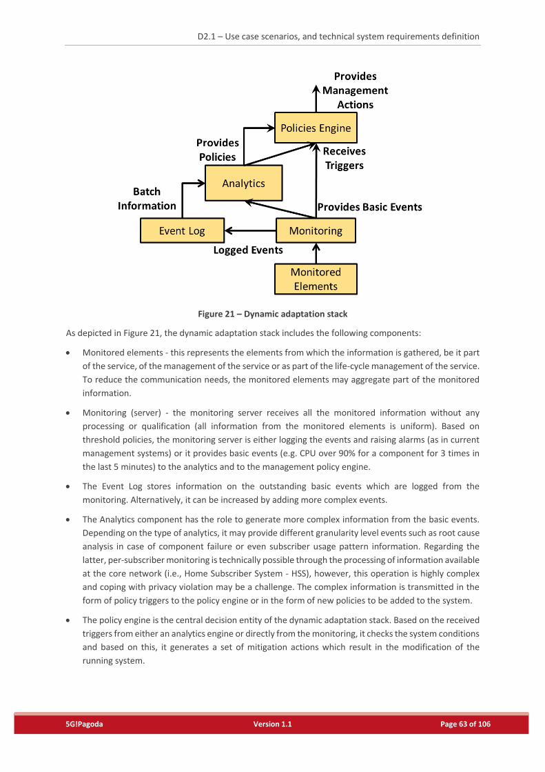
D2.1 – Use case scenarios, and technical system requirements definition
5G!Pagoda Version 1.1 Page 63 of 106
Figure 21 – Dynamic adaptation stack
As depicted in Figure 21, the dynamic adaptation stack includes the following components:
Monitored elements - this represents the elements from which the information is gathered, be it part
of the service, of the management of the service or as part of the life-cycle management of the service.
To reduce the communication needs, the monitored elements may aggregate part of the monitored
information.
Monitoring (server) - the monitoring server receives all the monitored information without any
processing or qualification (all information from the monitored elements is uniform). Based on
threshold policies, the monitoring server is either logging the events and raising alarms (as in current
management systems) or it provides basic events (e.g. CPU over 90% for a component for 3 times in
the last 5 minutes) to the analytics and to the management policy engine.
The Event Log stores information on the outstanding basic events which are logged from the
monitoring. Alternatively, it can be increased by adding more complex events.
The Analytics component has the role to generate more complex information from the basic events.
Depending on the type of analytics, it may provide different granularity level events such as root cause
analysis in case of component failure or even subscriber usage pattern information. Regarding the
latter, per-subscriber monitoring is technically possible through the processing of information available
at the core network (i.e., Home Subscriber System - HSS), however, this operation is highly complex
and coping with privacy violation may be a challenge. The complex information is transmitted in the
form of policy triggers to the policy engine or in the form of new policies to be added to the system.
The policy engine is the central decision entity of the dynamic adaptation stack. Based on the received
triggers from either an analytics engine or directly from the monitoring, it checks the system conditions
and based on this, it generates a set of mitigation actions which result in the modification of the
running system.
D2.1 – Use case scenarios, and technical system requirements definition
5G!Pagoda Version 1.1 Page 64 of 106
Additionally, to this system, an event broker may have to be added to the interconnection between the
various analytics engines, the monitoring server and the policy engine. The event broker has the role to
properly route the events between the different components.
5.2. Architecture Reference Model
For implementing the above-mentioned multi-slice concept, a set of high level architectural reference
models are proposed as shown in Figure 22, depending on the perspective towards the system: one for the
orchestration architecture, whereby the specifics of the service deployed in the multi-slice architecture are
transparent (i.e., it can work for any type of slice) and one wherein the functionality within the slice
template is detailed towards the appropriate functionalities for each of the features. The two solutions are
detailed in the following sections, including the functional definition of the network elements.
5.2.1. Orchestration Architecture
The orchestration architecture represents the perspective on the system from the multi-slice system
management side. The main functionality related to the life-cycle management of the slice and less to the
slice functionality itself, thus being the same, no matter which slice type is deployed and regardless the
domain.
A set of existing functions from the NFV environment as well as from dynamic adaptation stack are included
in the system. In the following, they are described together with the other new components introduced
into the system, making references towards existing specifications when needed.
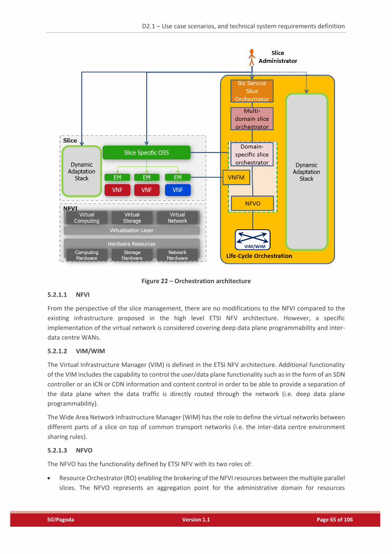
D2.1 – Use case scenarios, and technical system requirements definition
5G!Pagoda Version 1.1 Page 65 of 106
Figure 22 – Orchestration architecture
5.2.1.1 NFVI
From the perspective of the slice management, there are no modifications to the NFVI compared to the
existing infrastructure proposed in the high level ETSI NFV architecture. However, a specific
implementation of the virtual network is considered covering deep data plane programmability and inter-
data centre WANs.
5.2.1.2 VIM/WIM
The Virtual Infrastructure Manager (VIM) is defined in the ETSI NFV architecture. Additional functionality
of the VIM includes the capability to control the user/data plane functionality such as in the form of an SDN
controller or an ICN or CDN information and content control in order to be able to provide a separation of
the data plane when the data traffic is directly routed through the network (i.e. deep data plane
programmability).
The Wide Area Network Infrastructure Manager (WIM) has the role to define the virtual networks between
different parts of a slice on top of common transport networks (i.e. the inter-data centre environment
sharing rules).
5.2.1.3 NFVO
The NFVO has the functionality defined by ETSI NFV with its two roles of:
Resource Orchestrator (RO) enabling the brokering of the NFVI resources between the multiple parallel
slices. The NFVO represents an aggregation point for the administrative domain for resources
D2.1 – Use case scenarios, and technical system requirements definition
5G!Pagoda Version 1.1 Page 66 of 106
management. The NFVO communicates with multiple VIMs and WIMs and is able to allocate the
resources appropriately across them.
Network Service Orchestrator (NSO) providing indications on how the system should scale and where
the network functions should be placed following the Network Service Descriptor (NSD) information.
Additionally, the NSO is extended to support additional commands which result in the dynamic
changing of the NSD information. By this, the active service can be dynamically modified during
runtime with additional actions compared to the static NSD based decisions. For example, with this
new functionality, new VNFs can be added during runtime to a running system (e.g. a more performant
firewall in case of a network attack).
5.2.1.4 VNFM
The VNFM has the role defined by ETSI MANO specification to:
allocate appropriately resources to the VNFs or to delegate this operation to the NFVO,
to receive events on the completion of the specific operations and information on the dynamic
configurations, and
to configure through the Element Management (EM) the VNFs with the dynamic configurations.
5.2.1.5 Domain Specific Slice Orchestration
The domain specific slice orchestrator is able to communicate with multiple NFVOs located into the same
domain information on the specific slice split between the different NFVOs.
Additionally, the Domain Specific Slice orchestrator receives information on the life-cycle management of
the part of the slice which is allocated to run on the specific domain from the multi-domain slice
orchestrator. Note that this functionality is already offered by the northbound API of the NFVO in the form
of the processing of NSDs. It shall be noted that in the envisioned architecture (Figure 22), a domain-specific
slice orchestrator and NFVO may be the same entity.
5.2.1.6 Multi-domain slice orchestration
The multi-domain slice orchestrator has as main role to provide a slice on top of multiple administrative
domains. It contains the following functionality:
Receive requirements from the Business Service Slice orchestrator on the requirements for the specific
slice. The requirements may be received in a static description form such as TOSCA or an NSD file.
Establish secure connections to the multiple domain specific slice orchestrators
Acquire, if permissible, knowledge on the available resources in the specific administrative domains in
terms of available infrastructure and available services (e.g. stored virtual machine images)
Negotiate with the domain-specific slice orchestrators the resources and their locations to be allocated
for a slice customer
Make decisions based on the requirements received on the split of the slice functionality across the
multiple administrative domains
Command the installation of the slice over the multiple administrative domains
When the installation is successful, exchange connectivity parameters between the different domain
specific orchestrators to be able to stitch together the slice
Announce the tenant through the business slice orchestrator on the successful installation of the slice
as well as on the connectivity and management points
Inform the tenant, through the business slice orchestrator and/or the slice-specific OSS, of any SLA
breaches or any other types of major failures of the deployed slice
D2.1 – Use case scenarios, and technical system requirements definition
5G!Pagoda Version 1.1 Page 67 of 106
Dispose a slice from the multiple domains.
5.2.1.7 Business Service Slice Orchestration
The business service slice orchestrator has the role of a portal to advertise the possible services, to trigger
their deployment and in case of success, to transmit to the slice administrator the specific entry points to
the new slice management.
5.2.1.8 Dynamic adaptation stack (for the life-cycle management plane)
The life-cycle management plane has multiple points in which and through specific policies, the
functionality of the system may be adapted. Based on the monitored information from the slice, the NFVI
and the life-cycle management components, and the dynamic adaptation stack can provide the following
adaptations:
VIM level - migration of virtual machines, fault management and mitigation at the VM levels,
configuration of the infrastructure, infrastructure security protection, authentication and
authorization, resources scheduling for performance and resilience;
WIM level - establishment of new data paths, traffic steering between multiple data paths, QoS
classification and differentiation, application differentiation through deep data plane programmability;
NFVO level - network functions placement in the domain, scaling policies, automatic fault management,
resilience and security through application independent mechanisms, modifying the policies in
selecting domain specific ROs;
Domain specific slice orchestrator - modifying policies in selecting NFVOs
Multi-domain slice orchestrator - modifying the policies in selecting administrative domains, SLA
breaching reports;
Business Service Slice Orchestrator - transmitting to the tenant events in regard to the system on top
of which the slice is deployed (i.e. normal behaviour and exceptional events which may influence the
good functioning of the slice).
5.2.1.9 Slice Administrator
Using the system, the slice administrator is able to:
Request a services catalogue from the Business Service Slice Orchestrator
Select and configure a slice based on the services provided in the catalogue
Trigger the deployment of the slice according to the configured services
Administrating the dynamic adaptation stack in both the orchestration and within the slice as much as
allowed and possible through policies within the policy engine. Most probably this will be done through
pre-defined templates.
Administrating the services within the slice through policies within the slice specific OSS as well as
through user profiles.
5.2.2. Slice Architecture
The slice architecture includes all the components that compose the software network within the slice. The
proposed slice architecture is illustrated in Figure 23 and follows the slice template model described in the
previous sections.
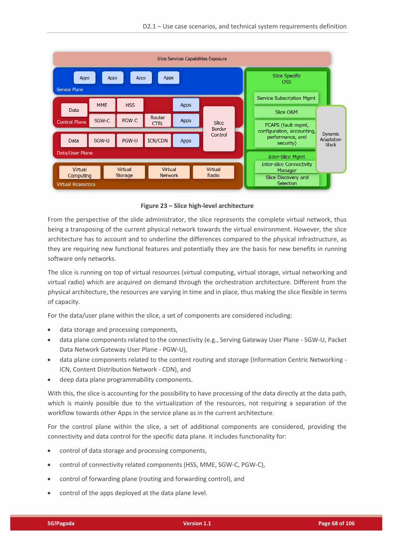
D2.1 – Use case scenarios, and technical system requirements definition
5G!Pagoda Version 1.1 Page 68 of 106
Figure 23 – Slice high-level architecture
From the perspective of the slide administrator, the slice represents the complete virtual network, thus
being a transposing of the current physical network towards the virtual environment. However, the slice
architecture has to account and to underline the differences compared to the physical infrastructure, as
they are requiring new functional features and potentially they are the basis for new benefits in running
software only networks.
The slice is running on top of virtual resources (virtual computing, virtual storage, virtual networking and
virtual radio) which are acquired on demand through the orchestration architecture. Different from the
physical architecture, the resources are varying in time and in place, thus making the slice flexible in terms
of capacity.
For the data/user plane within the slice, a set of components are considered including:
data storage and processing components,
data plane components related to the connectivity (e.g., Serving Gateway User Plane - SGW-U, Packet
Data Network Gateway User Plane - PGW-U),
data plane components related to the content routing and storage (Information Centric Networking -
ICN, Content Distribution Network - CDN), and
deep data plane programmability components.
With this, the slice is accounting for the possibility to have processing of the data directly at the data path,
which is mainly possible due to the virtualization of the resources, not requiring a separation of the
workflow towards other Apps in the service plane as in the current architecture.
For the control plane within the slice, a set of additional components are considered, providing the
connectivity and data control for the specific data plane. It includes functionality for:
control of data storage and processing components,
control of connectivity related components (HSS, MME, SGW-C, PGW-C),
control of forwarding plane (routing and forwarding control), and
control of the apps deployed at the data plane level.
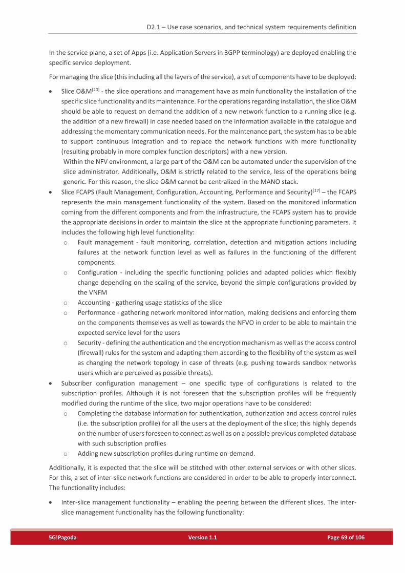
D2.1 – Use case scenarios, and technical system requirements definition
5G!Pagoda Version 1.1 Page 69 of 106
In the service plane, a set of Apps (i.e. Application Servers in 3GPP terminology) are deployed enabling the
specific service deployment.
For managing the slice (this including all the layers of the service), a set of components have to be deployed:
Slice O&M[20] - the slice operations and management have as main functionality the installation of the
specific slice functionality and its maintenance. For the operations regarding installation, the slice O&M
should be able to request on demand the addition of a new network function to a running slice (e.g.
the addition of a new firewall) in case needed based on the information available in the catalogue and
addressing the momentary communication needs. For the maintenance part, the system has to be able
to support continuous integration and to replace the network functions with more functionality
(resulting probably in more complex function descriptors) with a new version.
Within the NFV environment, a large part of the O&M can be automated under the supervision of the
slice administrator. Additionally, O&M is strictly related to the service, less of the operations being
generic. For this reason, the slice O&M cannot be centralized in the MANO stack.
Slice FCAPS (Fault Management, Configuration, Accounting, Performance and Security)[17] – the FCAPS
represents the main management functionality of the system. Based on the monitored information
coming from the different components and from the infrastructure, the FCAPS system has to provide
the appropriate decisions in order to maintain the slice at the appropriate functioning parameters. It
includes the following high level functionality:
o Fault management - fault monitoring, correlation, detection and mitigation actions including
failures at the network function level as well as failures in the functioning of the different
components.
o Configuration - including the specific functioning policies and adapted policies which flexibly
change depending on the scaling of the service, beyond the simple configurations provided by
the VNFM
o Accounting - gathering usage statistics of the slice
o Performance - gathering network monitored information, making decisions and enforcing them
on the components themselves as well as towards the NFVO in order to be able to maintain the
expected service level for the users
o Security - defining the authentication and the encryption mechanism as well as the access control
(firewall) rules for the system and adapting them according to the flexibility of the system as well
as changing the network topology in case of threats (e.g. pushing towards sandbox networks
users which are perceived as possible threats).
Subscriber configuration management – one specific type of configurations is related to the
subscription profiles. Although it is not foreseen that the subscription profiles will be frequently
modified during the runtime of the slice, two major operations have to be considered:
o Completing the database information for authentication, authorization and access control rules
(i.e. the subscription profile) for all the users at the deployment of the slice; this highly depends
on the number of users foreseen to connect as well as on a possible previous completed database
with such subscription profiles
o Adding new subscription profiles during runtime on-demand.
Additionally, it is expected that the slice will be stitched with other external services or with other slices.
For this, a set of inter-slice network functions are considered in order to be able to properly interconnect.
The functionality includes:
Inter-slice management functionality – enabling the peering between the different slices. The inter-
slice management functionality has the following functionality:
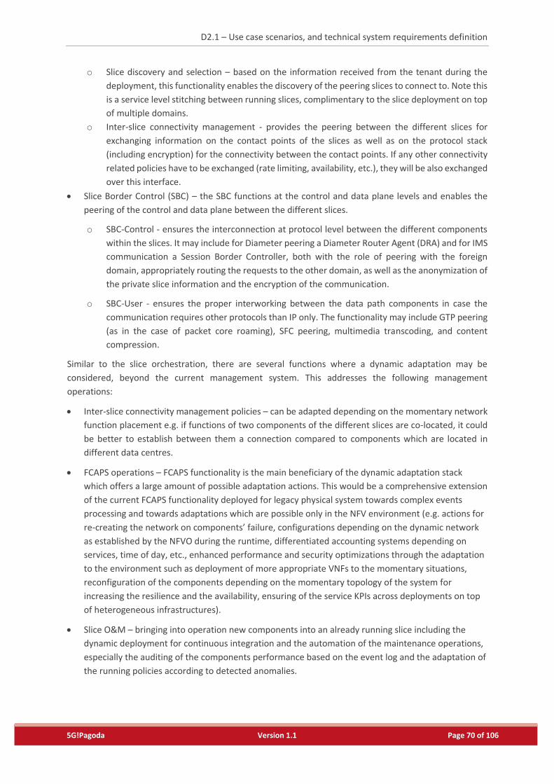
D2.1 – Use case scenarios, and technical system requirements definition
5G!Pagoda Version 1.1 Page 70 of 106
o Slice discovery and selection – based on the information received from the tenant during the
deployment, this functionality enables the discovery of the peering slices to connect to. Note this
is a service level stitching between running slices, complimentary to the slice deployment on top
of multiple domains.
o Inter-slice connectivity management - provides the peering between the different slices for
exchanging information on the contact points of the slices as well as on the protocol stack
(including encryption) for the connectivity between the contact points. If any other connectivity
related policies have to be exchanged (rate limiting, availability, etc.), they will be also exchanged
over this interface.
Slice Border Control (SBC) – the SBC functions at the control and data plane levels and enables the
peering of the control and data plane between the different slices.
o SBC-Control - ensures the interconnection at protocol level between the different components
within the slices. It may include for Diameter peering a Diameter Router Agent (DRA) and for IMS
communication a Session Border Controller, both with the role of peering with the foreign
domain, appropriately routing the requests to the other domain, as well as the anonymization of
the private slice information and the encryption of the communication.
o SBC-User - ensures the proper interworking between the data path components in case the
communication requires other protocols than IP only. The functionality may include GTP peering
(as in the case of packet core roaming), SFC peering, multimedia transcoding, and content
compression.
Similar to the slice orchestration, there are several functions where a dynamic adaptation may be
considered, beyond the current management system. This addresses the following management
operations:
Inter-slice connectivity management policies – can be adapted depending on the momentary network
function placement e.g. if functions of two components of the different slices are co-located, it could
be better to establish between them a connection compared to components which are located in
different data centres.
FCAPS operations – FCAPS functionality is the main beneficiary of the dynamic adaptation stack
which offers a large amount of possible adaptation actions. This would be a comprehensive extension
of the current FCAPS functionality deployed for legacy physical system towards complex events
processing and towards adaptations which are possible only in the NFV environment (e.g. actions for
re-creating the network on components’ failure, configurations depending on the dynamic network
as established by the NFVO during the runtime, differentiated accounting systems depending on
services, time of day, etc., enhanced performance and security optimizations through the adaptation
to the environment such as deployment of more appropriate VNFs to the momentary situations,
reconfiguration of the components depending on the momentary topology of the system for
increasing the resilience and the availability, ensuring of the service KPIs across deployments on top
of heterogeneous infrastructures).
Slice O&M – bringing into operation new components into an already running slice including the
dynamic deployment for continuous integration and the automation of the maintenance operations,
especially the auditing of the components performance based on the event log and the adaptation of
the running policies according to detected anomalies.
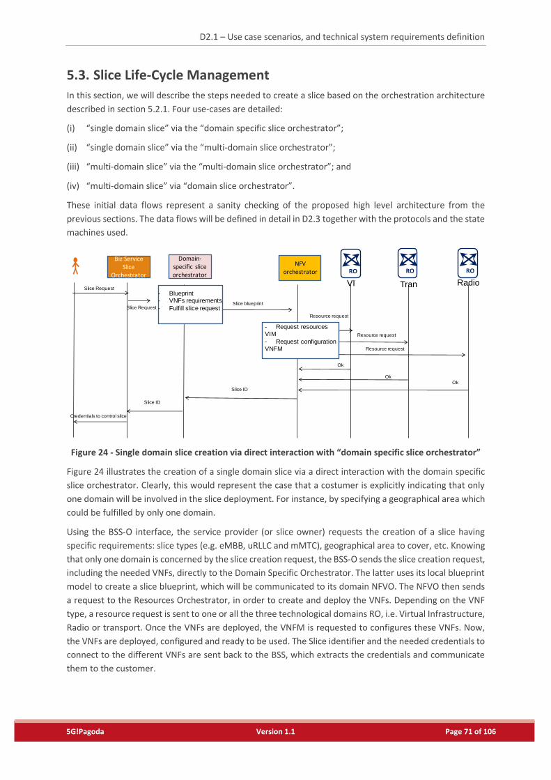
D2.1 – Use case scenarios, and technical system requirements definition
5G!Pagoda Version 1.1 Page 71 of 106
5.3. Slice Life-Cycle Management
In this section, we will describe the steps needed to create a slice based on the orchestration architecture
described in section 5.2.1. Four use-cases are detailed:
(i) “single domain slice” via the “domain specific slice orchestrator”;
(ii) “single domain slice” via the “multi-domain slice orchestrator”;
(iii) “multi-domain slice” via the “multi-domain slice orchestrator”; and
(iv) “multi-domain slice” via “domain slice orchestrator”.
These initial data flows represent a sanity checking of the proposed high level architecture from the
previous sections. The data flows will be defined in detail in D2.3 together with the protocols and the state
machines used.
Figure 24 - Single domain slice creation via direct interaction with “domain specific slice orchestrator”
Figure 24 illustrates the creation of a single domain slice via a direct interaction with the domain specific
slice orchestrator. Clearly, this would represent the case that a costumer is explicitly indicating that only
one domain will be involved in the slice deployment. For instance, by specifying a geographical area which
could be fulfilled by only one domain.
Using the BSS-O interface, the service provider (or slice owner) requests the creation of a slice having
specific requirements: slice types (e.g. eMBB, uRLLC and mMTC), geographical area to cover, etc. Knowing
that only one domain is concerned by the slice creation request, the BSS-O sends the slice creation request,
including the needed VNFs, directly to the Domain Specific Orchestrator. The latter uses its local blueprint
model to create a slice blueprint, which will be communicated to its domain NFVO. The NFVO then sends
a request to the Resources Orchestrator, in order to create and deploy the VNFs. Depending on the VNF
type, a resource request is sent to one or all the three technological domains RO, i.e. Virtual Infrastructure,
Radio or transport. Once the VNFs are deployed, the VNFM is requested to configures these VNFs. Now,
the VNFs are deployed, configured and ready to be used. The Slice identifier and the needed credentials to
connect to the different VNFs are sent back to the BSS, which extracts the credentials and communicate
them to the customer.
Slice Request
Slice ID
BizServiceSlice
Orchestrator
Domain-specificsliceorchestrator
NFVorchestrator RO RO RO
VI Tran Radio
Slice RequestSlice blueprint
-
- Request resourcesVIM
- Request configurationVNFM
Resource request
Resource request
Resource request
Slice ID
Credentials to control slice
-
- Blueprint- VNFs requirements
- Fulfill slice request
Ok
Ok
Ok
D2.1 – Use case scenarios, and technical system requirements definition
5G!Pagoda Version 1.1 Page 72 of 106
Figure 25 - Single domain slice creation via direct interaction with “multi-domain slice orchestrator”
Figure 25 shows the case of creating a single domain slice via the multi-domain slice orchestrator. This
would represent the case, where the BSS-O has no information on whether the resources should be created
from one domain or more. After receiving a request from the customer, the BSS-O sends a slice creation
request to the multi-domain slice orchestrator. The latter uses its blueprint model to build the slice
blueprint, which will be communicated to the domain specific slice orchestrator. It is important to note
that the multi-domain orchestrator selects the domain to be used for deploying VNFs using a local logic,
which takes into consideration the available resources information communicated by the domain specific
orchestrator(s), and other information like the geographical area to cover, etc. Then, the slice blueprint is
created. In some cases, after building the slice blueprint, the multi-domain specific slice orchestrator may
update its blueprint model according to the information received from the domain specific slice
orchestrator. In this use-case, the multi-domain orchestrator selects only one domain for deploying the
VNFs. Once receiving the slice blueprint, the Domain specific slice orchestrator adjusts the slice blueprint
according to its domain specific model. After that, using the updated slice blueprint, the VNFO follows the
same steps, as described in the precedent case, to deploy the VNFs.
Figure 26 - Multi-domain slice creation via direct interaction with “multi-domain slice orchestrator”
Slice Request
Slice ID
BizServiceSlice
Orchestrator
NFVorchestrator RO RO RO
VI Tran Radio
Slice RequestSlice blueprint
-
- Request resourcesVIM
- Request configurationVNFM
Resource request
Resource request
Resource request
Slice ID
Credentials to control slice
Ok
Ok
Ok
Multi-domainsliceorchestrator
-
- Negotiation withdomain specific Orch.
- Blueprint- VNFs requirements
- Fulfill slice request
- Blueprint adapted
Credentials to control slice
-
Slice Request
BizServiceSlice
Orchestrator
Multi-domainsliceorchestrator
Domain- NFVorchestrator
RORO
RO
VITran
Radio
Slice Request
Slice blueprint
Resource request
Slice Request
Multi-domain Slice ID
NFVorchestrator
Per domain Slice IDs
-
- Negotiation withdomain specific Orch.
- Blueprint- VNFs requirements
- Fulfill slice request
- Blueprint adapted
- Request resourcesVIM
- Request configurationVNFM
-
- Blueprint adjustment(domain specific)
- Fulfill slice request
NFVorchestrator
Domain-specificsliceorchestrator
Per domain Slice IDs
OK
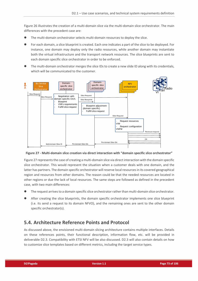
D2.1 – Use case scenarios, and technical system requirements definition
5G!Pagoda Version 1.1 Page 73 of 106
Figure 26 illustrates the creation of a multi-domain slice via the multi-domain slice orchestrator. The main
differences with the precedent case are:
The multi-domain orchestrator selects multi-domain resources to deploy the slice.
For each domain, a slice blueprint is created. Each one indicates a part of the slice to be deployed. For
instance, one domain may deploy only the radio resources, while another domain may instantiate
both the virtual infrastructure and the transport network resources. The slice blueprints are sent to
each domain specific slice orchestrator in order to be enforced.
The multi-domain orchestrator merges the slice IDs to create a new slide ID along with its credentials,
which will be communicated to the customer.
Figure 27 - Multi-domain slice creation via direct interaction with “domain specific slice orchestrator”
Figure 27 represents the case of creating a multi-domain slice via direct interaction with the domain specific
slice orchestrator. This would represent the situation when a customer deals with one domain, and the
latter has partners. The domain specific orchestrator will reserve local resources in its covered geographical
region and resources from other domains. The reason could be that the needed resources are located in
other regions or due the lack of local resources. The same steps are followed as defined in the precedent
case, with two main differences:
The request arrives to a domain specific slice orchestrator rather than multi-domain slice orchestrator.
After creating the slice blueprints, the domain specific orchestrator implements one slice blueprint
(i.e. its send a request to its domain NFVO), and the remaining ones are sent to the other domain
specific orchestrator(s).
5.4. Architecture Reference Points and Protocol
As discussed above, the envisioned multi-domain slicing architecture contains multiple interfaces. Details
on these references points, their functional description, information flow, etc. will be provided in
deliverable D2.3. Compatibility with ETSI NFV will be also discussed. D2.3 will also contain details on how
to customize slice templates based on different metrics, including the target service types.
-
Slice Request
BizServiceSlice
OrchestratorDomain- NFV
orchestratorRO
RORO
VITran
Radio
Slice Request
Slice Blueprintt
Resrouce request
Slice Request
Multi-domain Slice ID
NFVorchestrator
Per domain Slice IDs
-
- Negotiation withdomain specific Orch.
- Blueprint- VNFs requirements
- Fulfill slice request
- Request resourcesVIM
- Request configurationVNFM
-
- Blueprint adjustment(domain specific)
- Fulfill slice request
NFVorchestrator
Domain-specificsliceorchestrator
Per domain Slice IDs
OK
Domain-specificsliceorchestrator
Slice Request
D2.1 – Use case scenarios, and technical system requirements definition
5G!Pagoda Version 1.1 Page 74 of 106
6. Concluding Remarks
This deliverable lays the foundation for the research work to be carried out by 5G!Pagoda in the upcoming
months, particularly with regard to the development of the 5G!Pagoda architecture. To this end, we
carefully selected eight use-cases relevant to the 5G!Pagoda context. These use-cases were selected based
on the following six criteria: (1) the use cases that are not supported by current 4G technology, (2) the use
cases that can be supported in a much more effective way using the 5G technology, (3) the use cases that
have great potential for future local/international mobile markets, (4) the use cases that can create new
business model/opportunities for various business region operators, (5) the use cases that have a great
value from societal viewpoints, and (6) the use cases that have high relevance to the Tokyo Olympics. Each
use-case was analysed in terms of the involved stakeholders and technical requirements, allowing us to
refine and group the eight use-cases into three main reference scenarios: (i) Remote Monitoring in
industrial Domain, (ii) Tourism support and (iii) Office Roaming. These reference scenarios characterise the
main performance and functional requirements that 5G!Pagoda architecture should meet.
Aiming at meeting the technical requirements of the three reference scenarios, we introduced the first cut
of the high level architecture of 5G!Pagoda. We took three steps to illustrate the architecture model and
concept:
1) We first clarified the general concept defining mobile network slicing, slice high-level architecture
templates, life-cycle orchestration system, and dynamic adaptation stack;
2) We then drew the architecture reference model for implementing the architecture concept, and
a set of high level architectural reference models;
3) We finally specified a high-level processing form for the orchestration architecture. The 5G!Pagoda
architecture is devised to ensure not only single domain orchestration and management, but also
multi-domain by extending the reference model of the ETSI NFV architecture.
Based on the outcome of the present deliverable, the other WPs and tasks will elaborate the interfaces
and functional blocks, along with the necessary algorithms and mechanisms of the devised 5G!Pagoda
architecture. Furthermore, the detailed description of the three reference scenarios will serve as a
validator for the proposed 5G!Pagoda architecture. Here, it shall be emphasized that the 5G!Pagoda project
is considered agile, i.e., some of the requirements identified in this deliverable are subject to adjustment
per economic relevance as well as per unidentified requirements coming to the fore. Indeed, some in-
depth analysis of the use-cases and stakeholder may be required. This deliverable shall serve as a starting
point for achieving the project objectives, exercising the knowledge and expertise of the consortium
members.
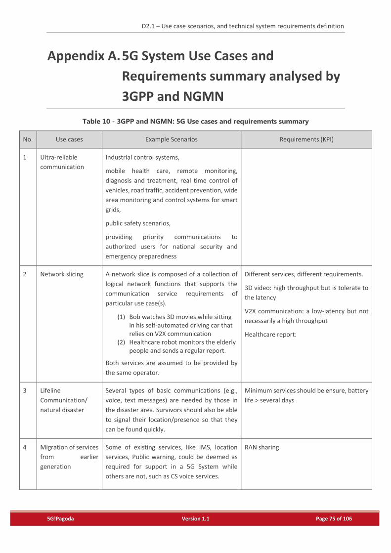
D2.1 – Use case scenarios, and technical system requirements definition
5G!Pagoda Version 1.1 Page 75 of 106
Appendix A. 5G System Use Cases and
Requirements summary analysed by
3GPP and NGMN
Table 10 - 3GPP and NGMN: 5G Use cases and requirements summary
No. Use cases Example Scenarios Requirements (KPI)
1 Ultra-reliable
communication
Industrial control systems,
mobile health care, remote monitoring,
diagnosis and treatment, real time control of
vehicles, road traffic, accident prevention, wide
area monitoring and control systems for smart
grids,
public safety scenarios,
providing priority communications to
authorized users for national security and
emergency preparedness
2 Network slicing
A network slice is composed of a collection of
logical network functions that supports the
communication service requirements of
particular use case(s).
(1) Bob watches 3D movies while sitting in his self-automated driving car that relies on V2X communication
(2) Healthcare robot monitors the elderly people and sends a regular report.
Both services are assumed to be provided by
the same operator.
Different services, different requirements.
3D video: high throughput but is tolerate to
the latency
V2X communication: a low-latency but not
necessarily a high throughput
Healthcare report:
3 Lifeline
Communication/
natural disaster
Several types of basic communications (e.g.,
voice, text messages) are needed by those in
the disaster area. Survivors should also be able
to signal their location/presence so that they
can be found quickly.
Minimum services should be ensure, battery
life > several days
4 Migration of services
from earlier
generation
Some of existing services, like IMS, location
services, Public warning, could be deemed as
required for support in a 5G System while
others are not, such as CS voice services.
RAN sharing
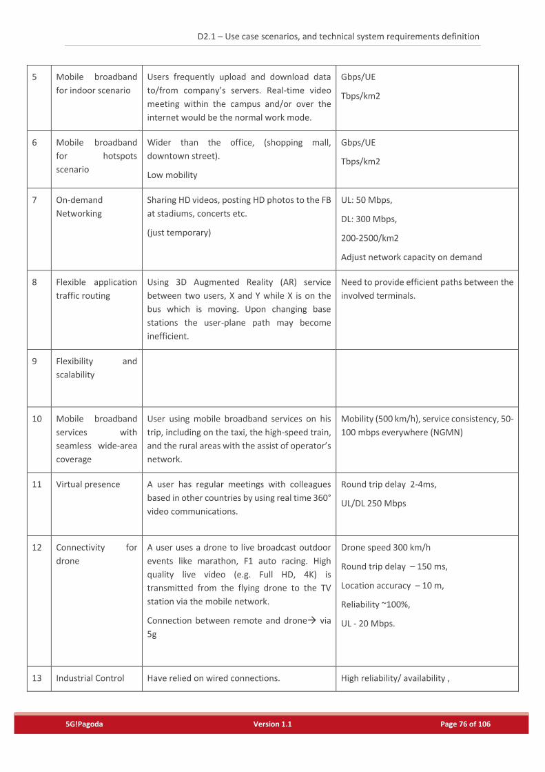
D2.1 – Use case scenarios, and technical system requirements definition
5G!Pagoda Version 1.1 Page 76 of 106
5 Mobile broadband
for indoor scenario
Users frequently upload and download data
to/from company’s servers. Real-time video
meeting within the campus and/or over the
internet would be the normal work mode.
Gbps/UE
Tbps/km2
6 Mobile broadband
for hotspots
scenario
Wider than the office, (shopping mall,
downtown street).
Low mobility
Gbps/UE
Tbps/km2
7 On-demand
Networking
Sharing HD videos, posting HD photos to the FB
at stadiums, concerts etc.
(just temporary)
UL: 50 Mbps,
DL: 300 Mbps,
200-2500/km2
Adjust network capacity on demand
8 Flexible application
traffic routing
Using 3D Augmented Reality (AR) service
between two users, X and Y while X is on the
bus which is moving. Upon changing base
stations the user-plane path may become
inefficient.
Need to provide efficient paths between the
involved terminals.
9 Flexibility and
scalability
10 Mobile broadband
services with
seamless wide-area
coverage
User using mobile broadband services on his
trip, including on the taxi, the high-speed train,
and the rural areas with the assist of operator’s
network.
Mobility (500 km/h), service consistency, 50-
100 mbps everywhere (NGMN)
11 Virtual presence A user has regular meetings with colleagues
based in other countries by using real time 360°
video communications.
Round trip delay 2-4ms,
UL/DL 250 Mbps
12 Connectivity for
drone
A user uses a drone to live broadcast outdoor
events like marathon, F1 auto racing. High
quality live video (e.g. Full HD, 4K) is
transmitted from the flying drone to the TV
station via the mobile network.
Connection between remote and drone via
5g
Drone speed 300 km/h
Round trip delay – 150 ms,
Location accuracy – 10 m,
Reliability ~100%,
UL - 20 Mbps.
13 Industrial Control Have relied on wired connections. High reliability/ availability ,
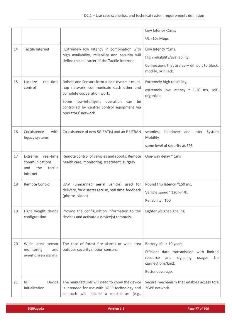
D2.1 – Use case scenarios, and technical system requirements definition
5G!Pagoda Version 1.1 Page 77 of 106
Low latency <1ms,
UL >10s Mbps
14 Tactile Internet "Extremely low latency in combination with
high availability, reliability and security will
define the character of the Tactile Internet"
Low latency ~1ms.
High reliability/availability.
Connections that are very difficult to block,
modify, or hijack.
15 Localize real-time
control
Robots and Sensors form a local dynamic multi-
hop network, communicate each other and
complete cooperation work.
Some low-intelligent operation can be
controlled by central control equipment via
operators’ network.
Extremely high reliability,
extremely low latency ~ 1-10 ms, self-
organized
16 Coexistence with
legacy systems
Co-existence of new 5G RAT(s) and an E-UTRAN seamless handover and Inter System
Mobility
same level of security as EPS
17 Extreme real-time
communications
and the tactile
internet
Remote control of vehicles and robots, Remote
health care, monitoring, treatment, surgery
One-way delay ~ 1ms
18 Remote Control UAV (unmanned aerial vehicle) used for
delivery, for disaster recuse, real time feedback
(photos, video)
Round trip latency ~150 ms,
Vehicle speed ~120 km/h,
Reliability ~100
19 Light weight device
configuration
Provide the configuration information to the
devices and activate a device(s) remotely.
Lighter weight signaling.
20 Wide area sensor
monitoring and
event driven alarms
The case of forest fire alarms or wide area
outdoor security motion sensors.
Battery life > 10 years.
Efficient data transmission with limited
resource and signaling usage. 1m
connections/km2.
Better coverage.
21 IoT Device
Initialization
The manufacturer will need to know the device
is intended for use with 3GPP technology and
as such will include a mechanism (e.g.,
Secure mechanism that enables access to a
3GPP network.
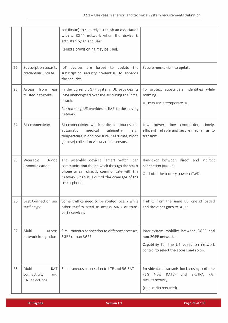
D2.1 – Use case scenarios, and technical system requirements definition
5G!Pagoda Version 1.1 Page 78 of 106
certificate) to securely establish an association
with a 3GPP network when the device is
activated by an end user.
Remote provisioning may be used.
22 Subscription security
credentials update
IoT devices are forced to update the
subscription security credentials to enhance
the security.
Secure mechanism to update
23 Access from less
trusted networks
In the current 3GPP system, UE provides its
IMSI unencrypted over the air during the initial
attach.
For roaming, UE provides its IMSI to the serving
network.
To protect subscribers’ identities while
roaming.
UE may use a temporary ID.
24 Bio-connectivity Bio-connectivity, which is the continuous and
automatic medical telemetry (e.g.,
temperature, blood pressure, heart-rate, blood
glucose) collection via wearable sensors.
Low power, low complexity, timely,
efficient, reliable and secure mechanism to
transmit.
25 Wearable Device
Communication
The wearable devices (smart watch) can
communication the network through the smart
phone or can directly communicate with the
network when it is out of the coverage of the
smart phone.
Handover between direct and indirect
connection (via UE)
Optimize the battery power of WD
26 Best Connection per
traffic type
Some traffics need to be routed locally while
other traffics need to access MNO or third-
party services.
Traffics from the same UE, one offloaded
and the other goes to 3GPP.
27 Multi access
network integration
Simultaneous connection to different accesses,
3GPP or non 3GPP
Inter-system mobility between 3GPP and
non-3GPP networks.
Capability for the UE based on network
control to select the access and so on.
28 Multi RAT
connectivity and
RAT selections
Simultaneous connection to LTE and 5G RAT Provide data transmission by using both the
<5G New RATs> and E-UTRA RAT
simultaneously
(Dual radio required).
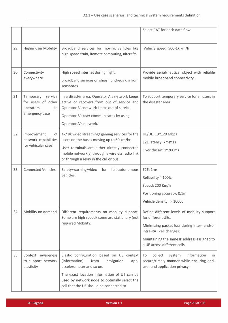
D2.1 – Use case scenarios, and technical system requirements definition
5G!Pagoda Version 1.1 Page 79 of 106
Select RAT for each data flow.
29 Higher user Mobility Broadband services for moving vehicles like
high speed train, Remote computing, aircrafts.
Vehicle speed: 500-1k km/h
30 Connectivity
everywhere
High speed internet during flight,
broadband services on ships hundreds km from
seashores
Provide aerial/nautical object with reliable
mobile broadband connectivity.
31 Temporary service
for users of other
operators in
emergency case
In a disaster area, Operator A’s network keeps
active or recovers from out of service and
Operator B’s network keeps out of service.
Operator B‘s user communicates by using
Operator A’s network.
To support temporary service for all users in
the disaster area.
32 Improvement of
network capabilities
for vehicular case
4k/ 8k video streaming/ gaming services for the
users on the buses moving up to 60 km/hr.
User terminals are either directly connected
mobile network(s) through a wireless radio link
or through a relay in the car or bus.
UL/DL: 10~120 Mbps
E2E latency: 7ms~1s
Over the air: 1~200ms
33 Connected Vehicles Safety/warning/video for full-autonomous
vehicles.
E2E: 1ms
Reliability ~ 100%
Speed: 200 Km/h
Positioning accuracy: 0.1m
Vehicle density : > 10000
34 Mobility on demand Different requirements on mobility support.
Some are high speed/ some are stationary (not
required Mobility)
Define different levels of mobility support
for different UEs.
Minimizing packet loss during inter- and/or
intra-RAT cell changes.
Maintaining the same IP address assigned to
a UE across different cells.
35 Context awareness
to support network
elasticity
Elastic configuration based on UE context
(information) from navigation App,
accelerometer and so on.
The exact location information of UE can be
used by network node to optimally select the
cell that the UE should be connected to.
To collect system information in
secure/timely manner while ensuring end-
user and application privacy.
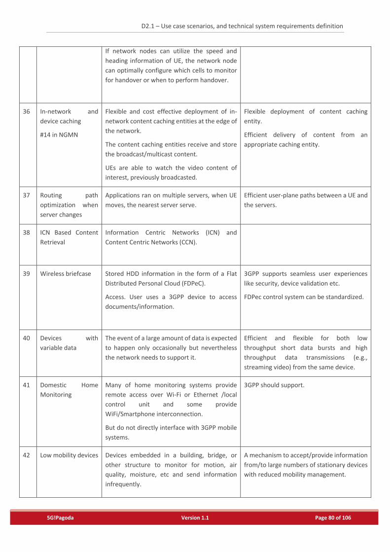
D2.1 – Use case scenarios, and technical system requirements definition
5G!Pagoda Version 1.1 Page 80 of 106
If network nodes can utilize the speed and
heading information of UE, the network node
can optimally configure which cells to monitor
for handover or when to perform handover.
36 In-network and
device caching
#14 in NGMN
Flexible and cost effective deployment of in-
network content caching entities at the edge of
the network.
The content caching entities receive and store
the broadcast/multicast content.
UEs are able to watch the video content of
interest, previously broadcasted.
Flexible deployment of content caching
entity.
Efficient delivery of content from an
appropriate caching entity.
37 Routing path
optimization when
server changes
Applications ran on multiple servers, when UE
moves, the nearest server serve.
Efficient user-plane paths between a UE and
the servers.
38 ICN Based Content
Retrieval
Information Centric Networks (ICN) and
Content Centric Networks (CCN).
39 Wireless briefcase Stored HDD information in the form of a Flat
Distributed Personal Cloud (FDPeC).
Access. User uses a 3GPP device to access
documents/information.
3GPP supports seamless user experiences
like security, device validation etc.
FDPec control system can be standardized.
40 Devices with
variable data
The event of a large amount of data is expected
to happen only occasionally but nevertheless
the network needs to support it.
Efficient and flexible for both low
throughput short data bursts and high
throughput data transmissions (e.g.,
streaming video) from the same device.
41 Domestic Home
Monitoring
Many of home monitoring systems provide
remote access over Wi-Fi or Ethernet /local
control unit and some provide
WiFi/Smartphone interconnection.
But do not directly interface with 3GPP mobile
systems.
3GPP should support.
42 Low mobility devices
Devices embedded in a building, bridge, or
other structure to monitor for motion, air
quality, moisture, etc and send information
infrequently.
A mechanism to accept/provide information
from/to large numbers of stationary devices
with reduced mobility management.
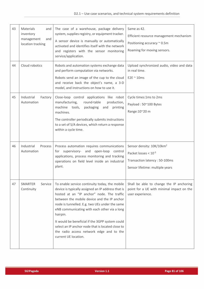
D2.1 – Use case scenarios, and technical system requirements definition
5G!Pagoda Version 1.1 Page 81 of 106
43 Materials and
inventory
management and
location tracking
The case of a warehouse, package delivery
system, supplies registry, or equipment tracker.
A sensor device is manually or automatically
activated and identifies itself with the network
and registers with the sensor monitoring
service/application.
Same as 42.
Efficient resource management mechanism
Positioning accuracy ~ 0.5m
Roaming for moving sensors.
44 Cloud robotics Robots and automation systems exchange data
and perform computation via networks.
Robots send an image of the cup to the cloud
and receive back the object’s name, a 3-D
model, and instructions on how to use it.
Upload synchronized audio, video and data
in real time.
E2E ~ 10ms
45 Industrial Factory
Automation
Close-loop control applications like robot
manufacturing, round-table production,
machine tools, packaging and printing
machines.
The controller periodically submits instructions
to a set of S/A devices, which return a response
within a cycle time.
Cycle times:1ms to 2ms
Payload : 50~100 Bytes
Range:10~20 m
46 Industrial Process
Automation
Process automation requires communications
for supervisory- and open-loop control
applications, process monitoring and tracking
operations on field level inside an industrial
plant.
Sensor density: 10K/10km2
Packet losses < 10-5
Transaction latency : 50-100ms
Sensor lifetime: multiple years
47
SMARTER Service
Continuity
To enable service continuity today, the mobile
device is typically assigned an IP address that is
hosted at an “IP anchor” node. The traffic
between the mobile device and the IP anchor
node is tunnelled. E.g. two UEs under the same
eNB communicating with each other via a long
hairpin.
It would be beneficial if the 3GPP system could
select an IP anchor node that is located close to
the radio access network edge and to the
current UE location.
Shall be able to change the IP anchoring
point for a UE with minimal impact on the
user experience.
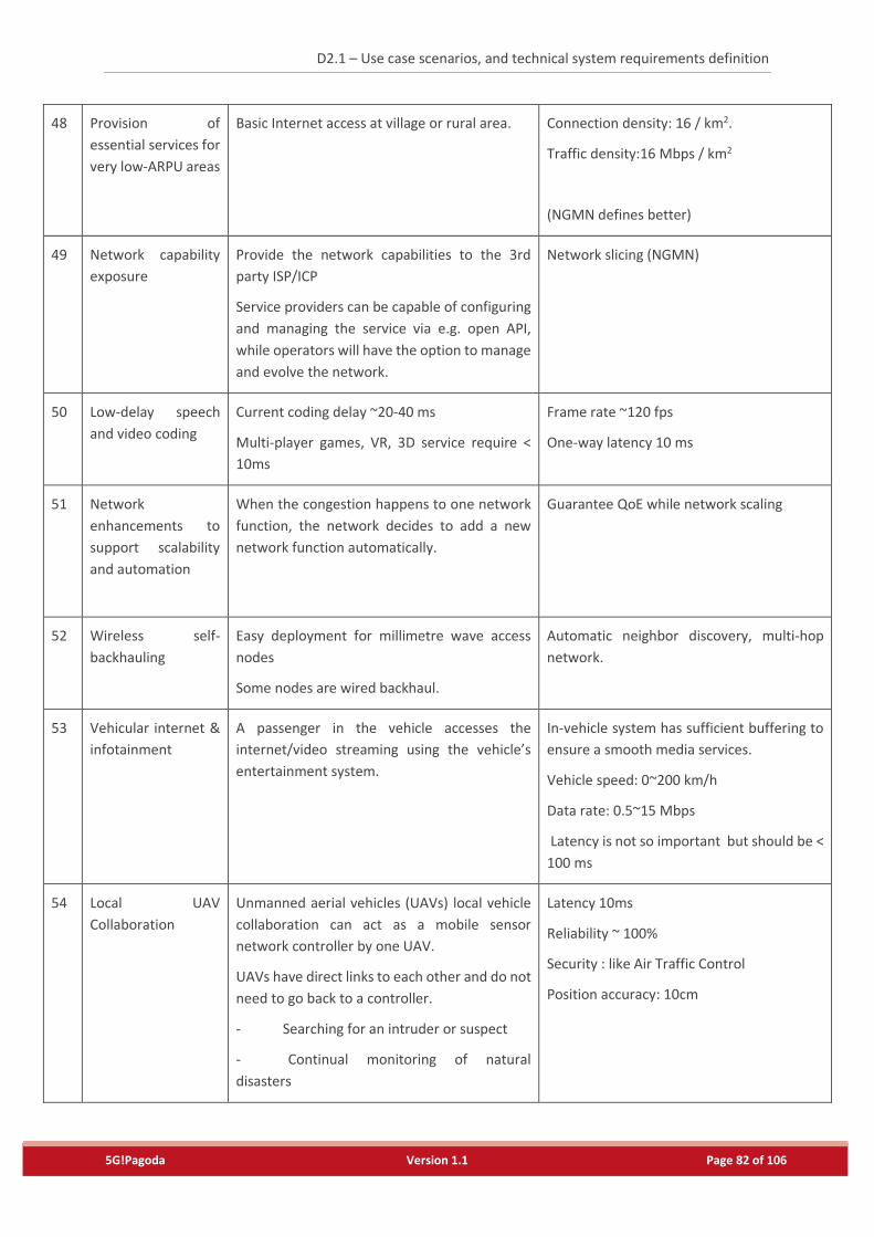
D2.1 – Use case scenarios, and technical system requirements definition
5G!Pagoda Version 1.1 Page 82 of 106
48 Provision of
essential services for
very low-ARPU areas
Basic Internet access at village or rural area. Connection density: 16 / km2.
Traffic density:16 Mbps / km2
(NGMN defines better)
49 Network capability
exposure
Provide the network capabilities to the 3rd
party ISP/ICP
Service providers can be capable of configuring
and managing the service via e.g. open API,
while operators will have the option to manage
and evolve the network.
Network slicing (NGMN)
50 Low-delay speech
and video coding
Current coding delay ~20-40 ms
Multi-player games, VR, 3D service require <
10ms
Frame rate ~120 fps
One-way latency 10 ms
51
Network
enhancements to
support scalability
and automation
When the congestion happens to one network
function, the network decides to add a new
network function automatically.
Guarantee QoE while network scaling
52 Wireless self-
backhauling
Easy deployment for millimetre wave access
nodes
Some nodes are wired backhaul.
Automatic neighbor discovery, multi-hop
network.
53 Vehicular internet &
infotainment
A passenger in the vehicle accesses the
internet/video streaming using the vehicle’s
entertainment system.
In-vehicle system has sufficient buffering to
ensure a smooth media services.
Vehicle speed: 0~200 km/h
Data rate: 0.5~15 Mbps
Latency is not so important but should be <
100 ms
54 Local UAV
Collaboration
Unmanned aerial vehicles (UAVs) local vehicle
collaboration can act as a mobile sensor
network controller by one UAV.
UAVs have direct links to each other and do not
need to go back to a controller.
- Searching for an intruder or suspect
- Continual monitoring of natural
disasters
Latency 10ms
Reliability ~ 100%
Security : like Air Traffic Control
Position accuracy: 10cm
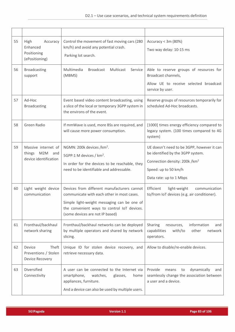
D2.1 – Use case scenarios, and technical system requirements definition
5G!Pagoda Version 1.1 Page 83 of 106
55 High Accuracy
Enhanced
Positioning
(ePositioning)
Control the movement of fast moving cars (280
km/h) and avoid any potential crash.
Parking lot search.
Accuracy < 3m (80%)
Two way delay: 10-15 ms
56
Broadcasting
support
Multimedia Broadcast Multicast Service
(MBMS)
Able to reserve groups of resources for
Broadcast channels,
Allow UE to receive selected broadcast
service by user.
57 Ad-Hoc
Broadcasting
Event based video content broadcasting, using
a slice of the local or temporary 3GPP system in
the environs of the event.
Reserve groups of resources temporarily for
scheduled Ad-Hoc broadcasts.
58 Green Radio If mmWave is used, more BSs are required, and
will cause more power consumption.
[1000] times energy efficiency compared to
legacy system. (100 times compared to 4G
system)
59 Massive internet of
things M2M and
device identification
NGMN: 200k devices /km2.
5GPP:1 M devices / km2.
In order for the devices to be reachable, they
need to be identifiable and addressable.
UE doesn’t need to be 3GPP, however it can
be identified by the 3GPP system.
Connection density: 200k /km2
Speed: up to 50 km/h
Data rate: up to 1 Mbps
60 Light weight device
communication
Devices from different manufacturers cannot
communicate with each other in most cases.
Simple light-weight messaging can be one of
the convenient ways to control IoT devices.
(some devices are not IP based)
Efficient light-weight communication
to/from IoT devices (e.g. air conditioner).
61 Fronthaul/backhaul
network sharing
Fronthaul/backhaul networks can be deployed
by multiple operators and shared by network
slicing.
Sharing resources, information and
capabilities with/to other network
operators.
62 Device Theft
Preventions / Stolen
Device Recovery
Unique ID for stolen device recovery, and
retrieve necessary data.
Allow to disable/re-enable devices.
63 Diversified
Connectivity
A user can be connected to the Internet via
smartphone, watches, glasses, home
appliances, furniture.
And a device can also be used by multiple users.
Provide means to dynamically and
seamlessly change the association between
a user and a device.
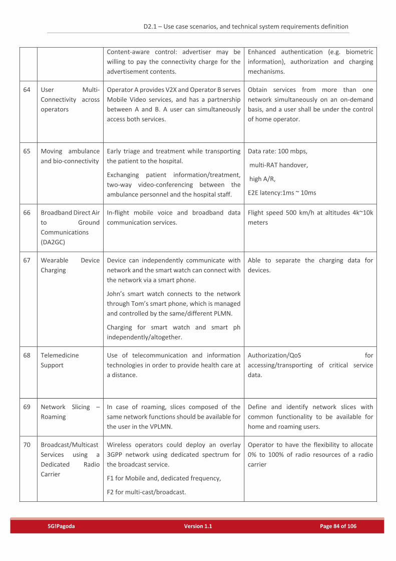
D2.1 – Use case scenarios, and technical system requirements definition
5G!Pagoda Version 1.1 Page 84 of 106
Content-aware control: advertiser may be
willing to pay the connectivity charge for the
advertisement contents.
Enhanced authentication (e.g. biometric
information), authorization and charging
mechanisms.
64 User Multi-
Connectivity across
operators
Operator A provides V2X and Operator B serves
Mobile Video services, and has a partnership
between A and B. A user can simultaneously
access both services.
Obtain services from more than one
network simultaneously on an on-demand
basis, and a user shall be under the control
of home operator.
65 Moving ambulance
and bio-connectivity
Early triage and treatment while transporting
the patient to the hospital.
Exchanging patient information/treatment,
two-way video-conferencing between the
ambulance personnel and the hospital staff.
Data rate: 100 mbps,
multi-RAT handover,
high A/R,
E2E latency:1ms ~ 10ms
66 Broadband Direct Air
to Ground
Communications
(DA2GC)
In-flight mobile voice and broadband data
communication services.
Flight speed 500 km/h at altitudes 4k~10k
meters
67
Wearable Device
Charging
Device can independently communicate with
network and the smart watch can connect with
the network via a smart phone.
John’s smart watch connects to the network
through Tom’s smart phone, which is managed
and controlled by the same/different PLMN.
Charging for smart watch and smart ph
independently/altogether.
Able to separate the charging data for
devices.
68 Telemedicine
Support
Use of telecommunication and information
technologies in order to provide health care at
a distance.
Authorization/QoS for
accessing/transporting of critical service
data.
69 Network Slicing –
Roaming
In case of roaming, slices composed of the
same network functions should be available for
the user in the VPLMN.
Define and identify network slices with
common functionality to be available for
home and roaming users.
70 Broadcast/Multicast
Services using a
Dedicated Radio
Carrier
Wireless operators could deploy an overlay
3GPP network using dedicated spectrum for
the broadcast service.
F1 for Mobile and, dedicated frequency,
F2 for multi-cast/broadcast.
Operator to have the flexibility to allocate
0% to 100% of radio resources of a radio
carrier
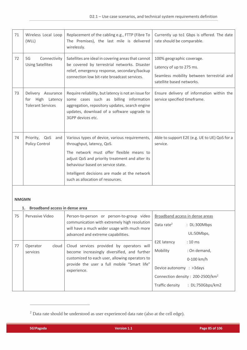
D2.1 – Use case scenarios, and technical system requirements definition
5G!Pagoda Version 1.1 Page 85 of 106
71 Wireless Local Loop
(WLL)
Replacement of the cabling e.g., FTTP (Fibre To
The Premises), the last mile is delivered
wirelessly.
Currently up to1 Gbps is offered. The date
rate should be comparable.
72 5G Connectivity
Using Satellites
Satellites are ideal in covering areas that cannot
be covered by terrestrial networks. Disaster
relief, emergency response, secondary/backup
connection low bit-rate broadcast services.
100% geographic coverage.
Latency of up to 275 ms.
Seamless mobility between terrestrial and
satellite based networks.
73 Delivery Assurance
for High Latency
Tolerant Services
Require reliability, but latency is not an issue for
some cases such as billing information
aggregation, repository updates, search engine
updates, download of a software upgrade to
3GPP devices etc.
Ensure delivery of information within the
service specified timeframe.
74 Priority, QoS and
Policy Control
Various types of device, various requirements,
throughput, latency, QoS.
The network must offer flexible means to
adjust QoS and priority treatment and alter its
behaviour based on service state.
Intelligent decisions are made at the network
such as allocation of resources.
Able to support E2E (e.g. UE to UE) QoS for a
service.
NMGMN
1. Broadband access in dense area
75 Pervasive Video Person-to-person or person-to-group video
communication with extremely high resolution
will have a much wider usage with much more
advanced and extreme capabilities.
Broadband access in dense areas
Data rate2 : DL:300Mbps
UL:50Mbps,
E2E latency : 10 ms
Mobility : On demand,
0-100 km/h
Device autonomy : >3days
Connection density : 200-2500/km2
Traffic density : DL:750Gbps/km2
77 Operator cloud
services
Cloud services provided by operators will
become increasingly diversified, and further
customized to each user, allowing operators to
provide the user a full mobile “Smart life”
experience.
2 Data rate should be understood as user experienced data rate (also at the cell edge).
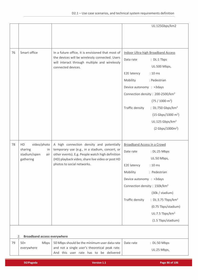
D2.1 – Use case scenarios, and technical system requirements definition
5G!Pagoda Version 1.1 Page 86 of 106
UL:125Gbps/km2
76
Smart office In a future office, it is envisioned that most of
the devices will be wirelessly connected. Users
will interact through multiple and wirelessly
connected devices.
Indoor Ultra-high Broadband Access
Data rate : DL:1 Tbps
UL:500 Mbps,
E2E latency : 10 ms
Mobility : Pedestrian
Device autonomy : >3days
Connection density : 200-2500/km2
(75 / 1000 m2)
Traffic density : DL:750 Gbps/km2
(15 Gbps/1000 m2)
UL:125 Gbps/km2
(2 Gbps/1000m2)
78 HD video/photo
sharing in
stadium/open air
gathering
A high connection density and potentially
temporary use (e.g., in a stadium, concert, or
other events). E.g. People watch high definition
(HD) playback video, share live video or post HD
photos to social networks.
Broadband Access in a Crowd
Date rate : DL:25 Mbps
UL:50 Mbps,
E2E latency : 10 ms
Mobility : Pedestrian
Device autonomy : >3days
Connection density : 150k/km2
(30k / stadium)
Traffic density : DL:3.75 Tbps/km2
(0.75 Tbps/stadium)
UL:7.5 Tbps/km2
(1.5 Tbps/stadium)
2. Broadband access everywhere
79 50+ Mbps
everywhere
50 Mbps should be the minimum user data rate
and not a single user’s theoretical peak rate.
And this user rate has to be delivered
Date rate : DL:50 Mbps
UL:25 Mbps,
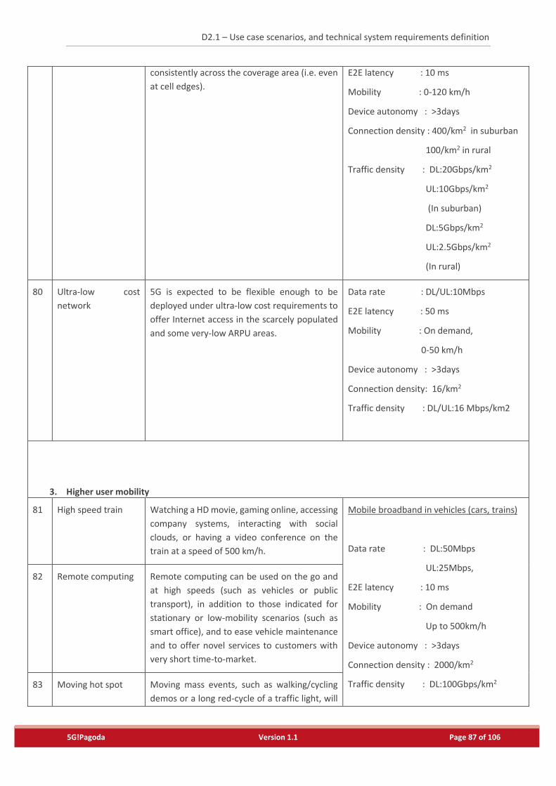
D2.1 – Use case scenarios, and technical system requirements definition
5G!Pagoda Version 1.1 Page 87 of 106
consistently across the coverage area (i.e. even
at cell edges).
E2E latency : 10 ms
Mobility : 0-120 km/h
Device autonomy : >3days
Connection density : 400/km2 in suburban
100/km2 in rural
Traffic density : DL:20Gbps/km2
UL:10Gbps/km2
(In suburban)
DL:5Gbps/km2
UL:2.5Gbps/km2
(In rural)
80 Ultra-low cost
network
5G is expected to be flexible enough to be
deployed under ultra-low cost requirements to
offer Internet access in the scarcely populated
and some very-low ARPU areas.
Data rate : DL/UL:10Mbps
E2E latency : 50 ms
Mobility : On demand,
0-50 km/h
Device autonomy : >3days
Connection density: 16/km2
Traffic density : DL/UL:16 Mbps/km2
3. Higher user mobility
81 High speed train Watching a HD movie, gaming online, accessing
company systems, interacting with social
clouds, or having a video conference on the
train at a speed of 500 km/h.
Mobile broadband in vehicles (cars, trains)
Data rate : DL:50Mbps
UL:25Mbps,
E2E latency : 10 ms
Mobility : On demand
Up to 500km/h
Device autonomy : >3days
Connection density : 2000/km2
Traffic density : DL:100Gbps/km2
82 Remote computing Remote computing can be used on the go and
at high speeds (such as vehicles or public
transport), in addition to those indicated for
stationary or low-mobility scenarios (such as
smart office), and to ease vehicle maintenance
and to offer novel services to customers with
very short time-to-market.
83 Moving hot spot Moving mass events, such as walking/cycling
demos or a long red-cycle of a traffic light, will
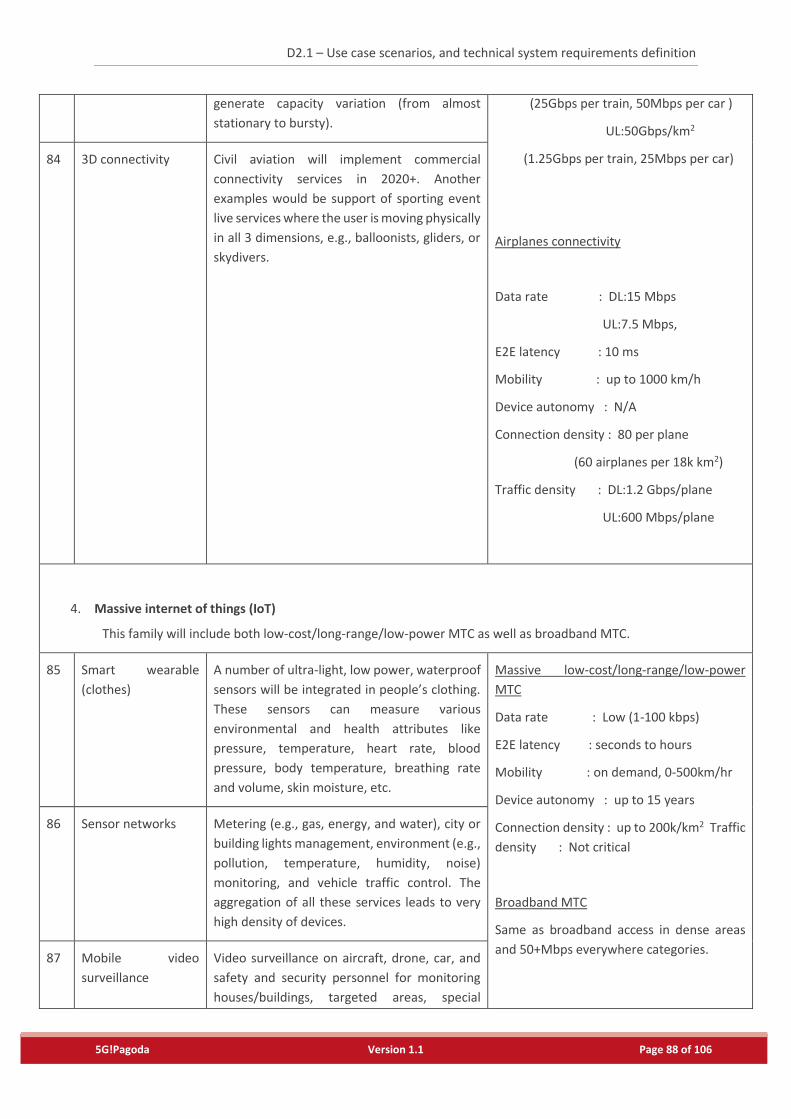
D2.1 – Use case scenarios, and technical system requirements definition
5G!Pagoda Version 1.1 Page 88 of 106
generate capacity variation (from almost
stationary to bursty).
(25Gbps per train, 50Mbps per car )
UL:50Gbps/km2
(1.25Gbps per train, 25Mbps per car)
Airplanes connectivity
Data rate : DL:15 Mbps
UL:7.5 Mbps,
E2E latency : 10 ms
Mobility : up to 1000 km/h
Device autonomy : N/A
Connection density : 80 per plane
(60 airplanes per 18k km2)
Traffic density : DL:1.2 Gbps/plane
UL:600 Mbps/plane
84 3D connectivity Civil aviation will implement commercial
connectivity services in 2020+. Another
examples would be support of sporting event
live services where the user is moving physically
in all 3 dimensions, e.g., balloonists, gliders, or
skydivers.
4. Massive internet of things (IoT)
This family will include both low-cost/long-range/low-power MTC as well as broadband MTC.
85 Smart wearable
(clothes)
A number of ultra-light, low power, waterproof
sensors will be integrated in people’s clothing.
These sensors can measure various
environmental and health attributes like
pressure, temperature, heart rate, blood
pressure, body temperature, breathing rate
and volume, skin moisture, etc.
Massive low-cost/long-range/low-power
MTC
Data rate : Low (1-100 kbps)
E2E latency : seconds to hours
Mobility : on demand, 0-500km/hr
Device autonomy : up to 15 years
Connection density : up to 200k/km2 Traffic
density : Not critical
Broadband MTC
Same as broadband access in dense areas
and 50+Mbps everywhere categories.
86 Sensor networks Metering (e.g., gas, energy, and water), city or
building lights management, environment (e.g.,
pollution, temperature, humidity, noise)
monitoring, and vehicle traffic control. The
aggregation of all these services leads to very
high density of devices.
87 Mobile video
surveillance
Video surveillance on aircraft, drone, car, and
safety and security personnel for monitoring
houses/buildings, targeted areas, special
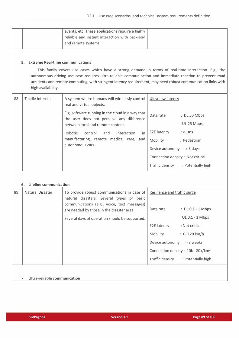
D2.1 – Use case scenarios, and technical system requirements definition
5G!Pagoda Version 1.1 Page 89 of 106
events, etc. These applications require a highly
reliable and instant interaction with back-end
and remote systems.
5. Extreme Real-time communications
This family covers use cases which have a strong demand in terms of real-time interaction. E.g., the
autonomous driving use case requires ultra-reliable communication and immediate reaction to prevent road
accidents and remote computing, with stringent latency requirement, may need robust communication links with
high availability.
88 Tactile Internet A system where humans will wirelessly control
real and virtual objects.
E.g. software running in the cloud in a way that
the user does not perceive any difference
between local and remote content.
Robotic control and interaction in
manufacturing, remote medical care, and
autonomous cars.
Ultra-low latency
Data rate : DL:50 Mbps
UL:25 Mbps,
E2E latency : < 1ms
Mobility : Pedestrian
Device autonomy : > 3 days
Connection density : Not critical
Traffic density : Potentially high
6. Lifeline communication
89 Natural Disaster To provide robust communications in case of
natural disasters. Several types of basic
communications (e.g., voice, text messages)
are needed by those in the disaster area.
Several days of operation should be supported.
Resilience and traffic surge
Data rate : DL:0.1 - 1 Mbps
UL:0.1 - 1 Mbps
E2E latency : Not critical
Mobility : 0- 120 km/h
Device autonomy : > 2 weeks
Connection density : 10k - 80k/km2
Traffic density : Potentially high
7. Ultra-reliable communication
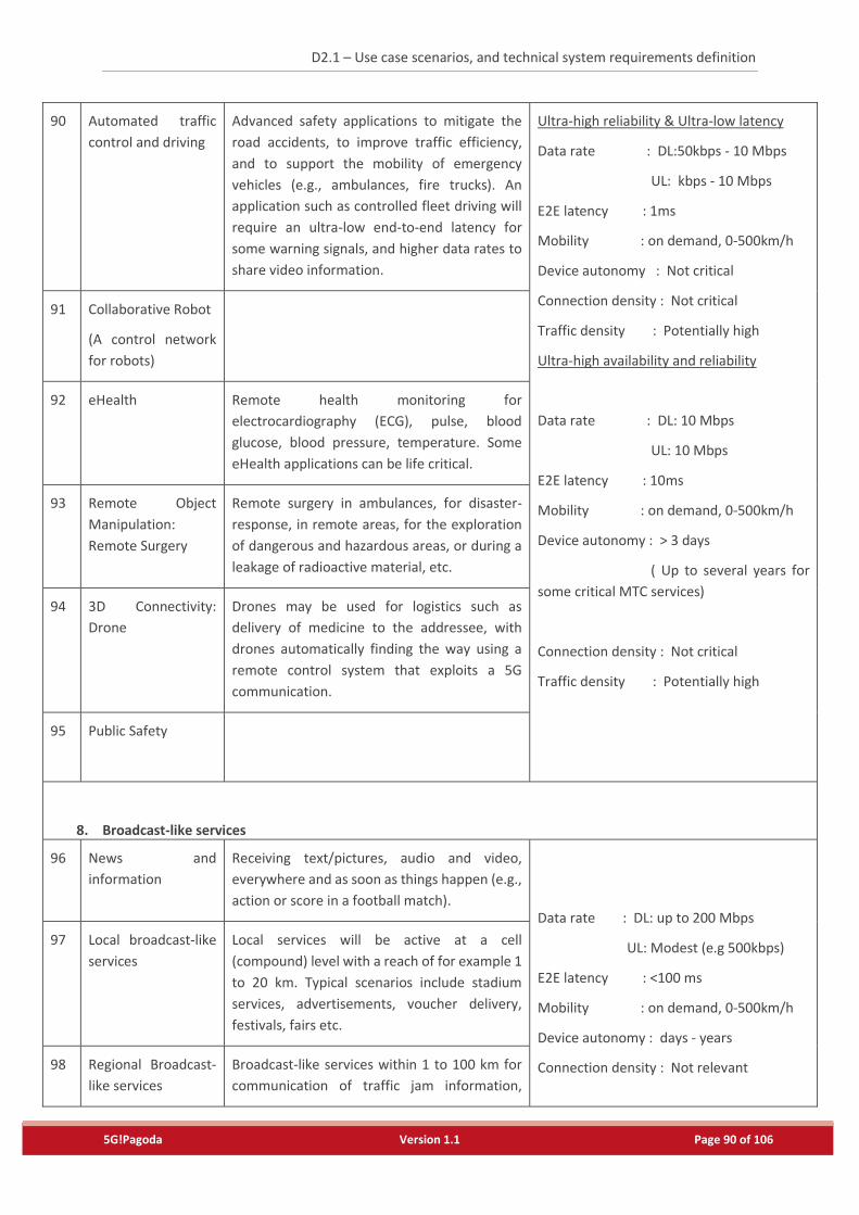
D2.1 – Use case scenarios, and technical system requirements definition
5G!Pagoda Version 1.1 Page 90 of 106
90 Automated traffic
control and driving
Advanced safety applications to mitigate the
road accidents, to improve traffic efficiency,
and to support the mobility of emergency
vehicles (e.g., ambulances, fire trucks). An
application such as controlled fleet driving will
require an ultra-low end-to-end latency for
some warning signals, and higher data rates to
share video information.
Ultra-high reliability & Ultra-low latency
Data rate : DL:50kbps - 10 Mbps
UL: kbps - 10 Mbps
E2E latency : 1ms
Mobility : on demand, 0-500km/h
Device autonomy : Not critical
Connection density : Not critical
Traffic density : Potentially high
Ultra-high availability and reliability
Data rate : DL: 10 Mbps
UL: 10 Mbps
E2E latency : 10ms
Mobility : on demand, 0-500km/h
Device autonomy : > 3 days
( Up to several years for
some critical MTC services)
Connection density : Not critical
Traffic density : Potentially high
91 Collaborative Robot
(A control network
for robots)
92 eHealth Remote health monitoring for
electrocardiography (ECG), pulse, blood
glucose, blood pressure, temperature. Some
eHealth applications can be life critical.
93 Remote Object
Manipulation:
Remote Surgery
Remote surgery in ambulances, for disaster-
response, in remote areas, for the exploration
of dangerous and hazardous areas, or during a
leakage of radioactive material, etc.
94 3D Connectivity:
Drone
Drones may be used for logistics such as
delivery of medicine to the addressee, with
drones automatically finding the way using a
remote control system that exploits a 5G
communication.
95 Public Safety
8. Broadcast-like services
96 News and
information
Receiving text/pictures, audio and video,
everywhere and as soon as things happen (e.g.,
action or score in a football match).
Data rate : DL: up to 200 Mbps
UL: Modest (e.g 500kbps)
E2E latency : <100 ms
Mobility : on demand, 0-500km/h
Device autonomy : days - years
Connection density : Not relevant
97 Local broadcast-like
services
Local services will be active at a cell
(compound) level with a reach of for example 1
to 20 km. Typical scenarios include stadium
services, advertisements, voucher delivery,
festivals, fairs etc.
98 Regional Broadcast-
like services
Broadcast-like services within 1 to 100 km for
communication of traffic jam information,
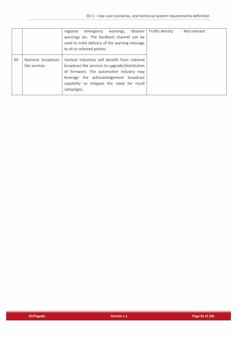
D2.1 – Use case scenarios, and technical system requirements definition
5G!Pagoda Version 1.1 Page 91 of 106
regional emergency warnings, disaster
warnings etc. The feedback channel can be
used to track delivery of the warning message
to all or selected parties.
Traffic density : Not relevant
99 National broadcast-
like services
Vertical industries will benefit from national
broadcast like services to upgrade/distribution
of firmware. The automotive industry may
leverage the acknowledgement broadcast
capability to mitigate the need for recall
campaigns.
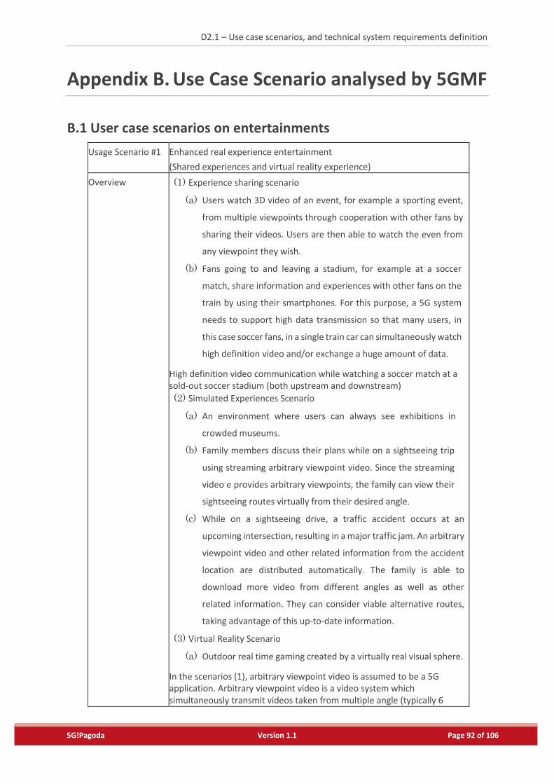
D2.1 – Use case scenarios, and technical system requirements definition
5G!Pagoda Version 1.1 Page 92 of 106
Appendix B. Use Case Scenario analysed by 5GMF
B.1 User case scenarios on entertainments
Usage Scenario #1 Enhanced real experience entertainment
(Shared experiences and virtual reality experience)
Overview (1) Experience sharing scenario
(a) Users watch 3D video of an event, for example a sporting event,
from multiple viewpoints through cooperation with other fans by
sharing their videos. Users are then able to watch the even from
any viewpoint they wish.
(b) Fans going to and leaving a stadium, for example at a soccer
match, share information and experiences with other fans on the
train by using their smartphones. For this purpose, a 5G system
needs to support high data transmission so that many users, in
this case soccer fans, in a single train car can simultaneously watch
high definition video and/or exchange a huge amount of data.
High definition video communication while watching a soccer match at a sold-out soccer stadium (both upstream and downstream)
(2) Simulated Experiences Scenario
(a) An environment where users can always see exhibitions in
crowded museums.
(b) Family members discuss their plans while on a sightseeing trip
using streaming arbitrary viewpoint video. Since the streaming
video e provides arbitrary viewpoints, the family can view their
sightseeing routes virtually from their desired angle.
(c) While on a sightseeing drive, a traffic accident occurs at an
upcoming intersection, resulting in a major traffic jam. An arbitrary
viewpoint video and other related information from the accident
location are distributed automatically. The family is able to
download more video from different angles as well as other
related information. They can consider viable alternative routes,
taking advantage of this up-to-date information.
(3) Virtual Reality Scenario
(a) Outdoor real time gaming created by a virtually real visual sphere.
In the scenarios (1), arbitrary viewpoint video is assumed to be a 5G application. Arbitrary viewpoint video is a video system which simultaneously transmit videos taken from multiple angle (typically 6
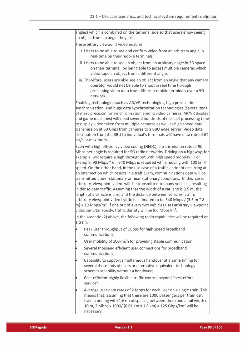
D2.1 – Use case scenarios, and technical system requirements definition
5G!Pagoda Version 1.1 Page 93 of 106
angles) which is combined on the terminal side so that users enjoy seeing an object from an angle they like.
The arbitrary viewpoint video enables;
i. Users to be able to see and confirm video from an arbitrary angle in real-time on their mobile terminals.
ii. Users to be able to see an object from an arbitrary angle in 3D space on their terminal, by being able to access multiple cameras which video-tape an object from a different angle.
iii. Therefore, users are able see an object from an angle that any camera operator would not be able to shoot in real time through processing video data from different mobile terminals over a 5G network.
Enabling technologies such as AR/VR technologies, high precise time synchronization, and huge data synchronization technologies (several tens of msec precision for synchronization among video cameras, AR/VR display and game machines) will need several hundreds of msec of processing time to display video taken from multiple cameras as well as high speed data transmission at 60 Gbps from cameras to a BBU edge server. Video data distribution from the BBU to individual’s terminals will have data rate of 6T bit/s at maximum.
Even with high efficiency video coding (HEDC), a transmission rate of 90 Mbps per angle is required for 5G radio networks. Driving on a highway, for example, will require a high throughput with high speed mobility. For example, 90 Mbps * 6 = 540 Mbps is required while moving with 100 km/h speed. On the other hand, in the use case of a traffic accident occurring at an intersection which results in a traffic jam, communications data will be transmitted under stationary or near stationary conditions. In this case, arbitrary viewpoint video will be transmitted to many vehicles, resulting in dense data traffic. Assuming that the width of a car lane is 3.5 m, the length of a vehicle is 5 m, and the distance between vehicles is 3 m, arbitrary viewpoint video traffic is estimated to be 540 Mbps / (3.5 m * 8 m) = 19 Mbps/m2. If one out of every two vehicles uses arbitrary viewpoint video simultaneously, traffic density will be 9.6 Mbps/m2.
In the scenario (2) above, the following radio capabilities will be required on a train:
Peak user throughput of 1Gbps for high speed broadband communications;
User mobility of 100km/h for providing stable communication;
Several thousand efficient user connections for broadband communications;
Capability to support simultaneous handover at a same timing for several thousands of users or alternative equivalent technology scheme/capability without a handover;
Cost-efficient highly flexible traffic control beyond “best effort service”;
Average user data rates of 2 Mbps for each user on a single train. This means that, assuming that there are 1000 passengers per train car, trains running with 1.6km of spacing between them and a rail width of 10 m, 2 Mbps x 1000/ (0.01 km x 1.6 km) = 125 Gbps/km2 will be necessary.
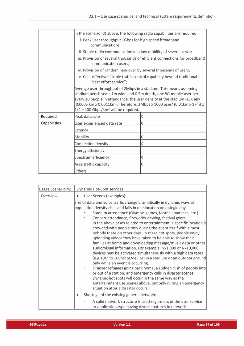
D2.1 – Use case scenarios, and technical system requirements definition
5G!Pagoda Version 1.1 Page 94 of 106
In the scenario (3) above, the following radio capabilities are required:
i. Peak user throughput 1Gbps for high speed broadband communications;
ii. Stable radio communication at a low mobility of several km/h;
iii. Provision of several thousands of efficient connections for broadband communication users;
iv. Provision of random handover by several thousands of users;
v. Cost-effective flexible traffic control capability beyond traditional “best effort service”;
Average user throughput of 2Mbps in a stadium. This means assuming stadium bench seats 1m wide and 0.5m depth, one 5G mobile user per every 10 people in attendance, the user density at the stadium is1 user/ (0.0005 km x 0.0011km). Therefore, 2Mbps x 1000 user/ (0.01km x 1km) x 1/4 = 400 Gbps/km2 will be required.
Required
Capabilities
Peak data rate X
User experienced data rate X
Latency
Mobility X
Connection density X
Energy efficiency
Spectrum efficiency X
Area traffic capacity X
Others
Usage Scenario #2 Dynamic Hot-Spot services
Overview User Scenes (examples):
Size of data and voice traffic change dramatically in dynamic ways as population density rises and falls in one location on a single day.
- Stadium attendance (Olympic games, football matches, etc.) - Concert attendance, fireworks viewing, festival goers
In the above cases related to entertainment, a specific location is crowded with people only during the event itself with almost nobody there on other days. In these hot spots, people enjoy uploading videos they have taken to be able to show their families at home and downloading message/music data or other audio/visual information. For example, Nx1,000 or Nx10,000 devices may be activated simultaneously with a high data rates (e.g.10M to 100Mbps/device) in a stadium or an outdoor ground only while an event is occurring.
- Disaster refugees going back home, a sudden rush of people into or out of a station, and emergency calls in disaster scenes. Dynamic hot spots will occur in the same way as the entertainment use scenes above, but only during an emergency situation after a disaster occurs.
Shortage of the existing general network:
- A solid network structure is used regardless of the user service or application type having diverse natures in network.
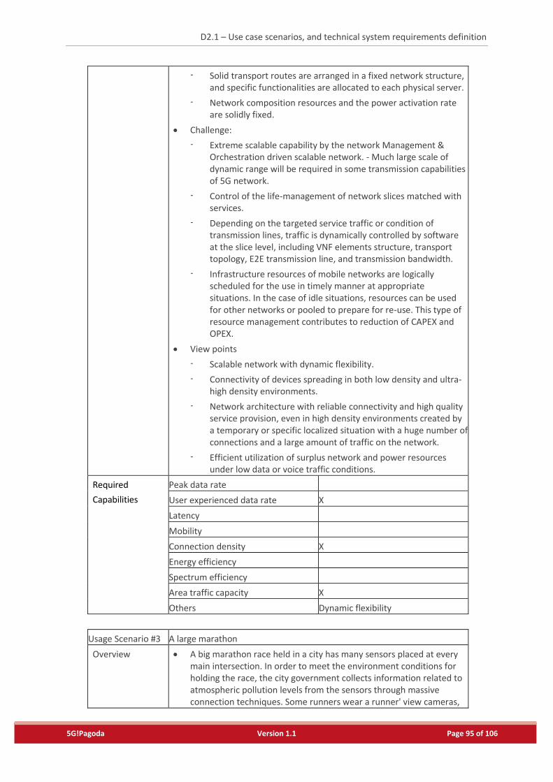
D2.1 – Use case scenarios, and technical system requirements definition
5G!Pagoda Version 1.1 Page 95 of 106
- Solid transport routes are arranged in a fixed network structure, and specific functionalities are allocated to each physical server.
- Network composition resources and the power activation rate are solidly fixed.
Challenge:
- Extreme scalable capability by the network Management & Orchestration driven scalable network. - Much large scale of dynamic range will be required in some transmission capabilities of 5G network.
- Control of the life-management of network slices matched with services.
- Depending on the targeted service traffic or condition of transmission lines, traffic is dynamically controlled by software at the slice level, including VNF elements structure, transport topology, E2E transmission line, and transmission bandwidth.
- Infrastructure resources of mobile networks are logically scheduled for the use in timely manner at appropriate situations. In the case of idle situations, resources can be used for other networks or pooled to prepare for re-use. This type of resource management contributes to reduction of CAPEX and OPEX.
View points
- Scalable network with dynamic flexibility.
- Connectivity of devices spreading in both low density and ultra-high density environments.
- Network architecture with reliable connectivity and high quality service provision, even in high density environments created by a temporary or specific localized situation with a huge number of connections and a large amount of traffic on the network.
- Efficient utilization of surplus network and power resources under low data or voice traffic conditions.
Required
Capabilities
Peak data rate
User experienced data rate X
Latency
Mobility
Connection density X
Energy efficiency
Spectrum efficiency
Area traffic capacity X
Others Dynamic flexibility
Usage Scenario #3 A large marathon
Overview A big marathon race held in a city has many sensors placed at every main intersection. In order to meet the environment conditions for holding the race, the city government collects information related to atmospheric pollution levels from the sensors through massive connection techniques. Some runners wear a runner' view cameras,
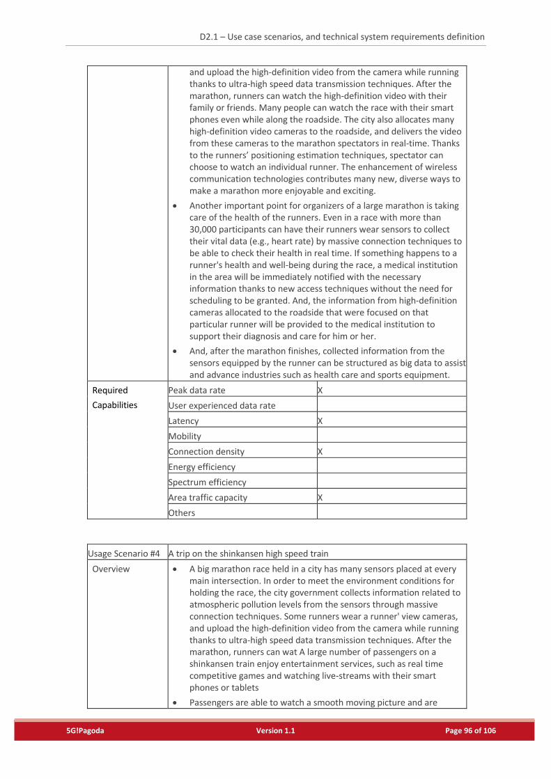
D2.1 – Use case scenarios, and technical system requirements definition
5G!Pagoda Version 1.1 Page 96 of 106
and upload the high-definition video from the camera while running thanks to ultra-high speed data transmission techniques. After the marathon, runners can watch the high-definition video with their family or friends. Many people can watch the race with their smart phones even while along the roadside. The city also allocates many high-definition video cameras to the roadside, and delivers the video from these cameras to the marathon spectators in real-time. Thanks to the runners’ positioning estimation techniques, spectator can choose to watch an individual runner. The enhancement of wireless communication technologies contributes many new, diverse ways to make a marathon more enjoyable and exciting.
Another important point for organizers of a large marathon is taking care of the health of the runners. Even in a race with more than 30,000 participants can have their runners wear sensors to collect their vital data (e.g., heart rate) by massive connection techniques to be able to check their health in real time. If something happens to a runner's health and well-being during the race, a medical institution in the area will be immediately notified with the necessary information thanks to new access techniques without the need for scheduling to be granted. And, the information from high-definition cameras allocated to the roadside that were focused on that particular runner will be provided to the medical institution to support their diagnosis and care for him or her.
And, after the marathon finishes, collected information from the sensors equipped by the runner can be structured as big data to assist and advance industries such as health care and sports equipment.
Required
Capabilities
Peak data rate X
User experienced data rate
Latency X
Mobility
Connection density X
Energy efficiency
Spectrum efficiency
Area traffic capacity X
Others
Usage Scenario #4 A trip on the shinkansen high speed train
Overview A big marathon race held in a city has many sensors placed at every main intersection. In order to meet the environment conditions for holding the race, the city government collects information related to atmospheric pollution levels from the sensors through massive connection techniques. Some runners wear a runner' view cameras, and upload the high-definition video from the camera while running thanks to ultra-high speed data transmission techniques. After the marathon, runners can wat A large number of passengers on a shinkansen train enjoy entertainment services, such as real time competitive games and watching live-streams with their smart phones or tablets
Passengers are able to watch a smooth moving picture and are

D2.1 – Use case scenarios, and technical system requirements definition
5G!Pagoda Version 1.1 Page 97 of 106
content with the quality despite being on a high speed train.
Reduce power consumption of base stations and terminals respectively.
Technology for high capacity, adaptive beamforming and group mobility are necessary.
Similar cases include:
- Cars on the highway (Especially a bus where a large number of passengers are in movement simultaneously)
- Ships
- Airplanes (when use of terminals is allowed even during in takeoff and landing).
Required
Capabilities
Peak data rate
User experienced data rate X
Latency
Mobility X
Connection density X
Energy efficiency X
Spectrum efficiency
Area traffic capacity X
Others
Usage Scenario #5 Content downloads by commuters
Overview A user can instantaneously download large-volume files when the user touches their mobile device to am HRCP (high-rate close proximity) access point, for example an automatic ticket gate. An example scenario: When the transmission rate is 2 Gbit/s, downloading time for a 30-minute 50 MB video file will be 220 msec.
- Mitigates wireless traffic loads in 5G mobile networks, by downloading large-volume files at the HRCP access point.
- Reduces power consumption on the mobile device, because wireless communication is not required while playing video, unlike streaming usage.
Required technologies include: (1) high-rate multi-Gbit/s wireless transmission, (2) device management function that turns on the wireless module only during downloading, and (3) cache mechanisms for delivering the content file to the HRCP access point where the download will occur.
- Radio access technologies using unlicensed bands will be employed for (1).
- To realize (2) and (3), new management/control functions that interoperate with 5G mobile networks are needed.
Required
Capabilities
Peak data rate X
User experienced data rate X
Latency
Mobility
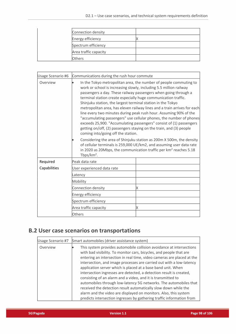
D2.1 – Use case scenarios, and technical system requirements definition
5G!Pagoda Version 1.1 Page 98 of 106
Connection density
Energy efficiency X
Spectrum efficiency
Area traffic capacity
Others
Usage Scenario #6 Communications during the rush hour commute
Overview In the Tokyo metropolitan area, the number of people commuting to work or school is increasing slowly, including 5.5 million railway passengers a day. These railway passengers when going through a terminal station create especially huge communication traffic. Shinjuku station, the largest terminal station in the Tokyo metropolitan area, has eleven railway lines and a train arrives for each line every two minutes during peak rush hour. Assuming 90% of the "accumulating passengers" use cellular phones, the number of phones exceeds 25,900. "Accumulating passengers" consist of (1) passengers getting on/off, (2) passengers staying on the train, and (3) people coming into/going off the station.
Considering the area of Shinjuku station as 200m X 500m, the density of cellular terminals is 259,000 UE/km2, and assuming user data rate in 2020 as 20Mbps, the communication traffic per km2 reaches 5.18 Tbps/km2.
Required
Capabilities
Peak data rate
User experienced data rate
Latency
Mobility
Connection density X
Energy efficiency
Spectrum efficiency
Area traffic capacity X
Others
B.2 User case scenarios on transportations
Usage Scenario #7 Smart automobiles (driver assistance system)
Overview This system provides automobile collision avoidance at intersections with bad visibility. To monitor cars, bicycles, and people that are entering an intersection in real time, video cameras are placed at the intersection, and image processes are carried out with a low-latency application server which is placed at a base band unit. When intersection ingresses are detected, a detection result is created, consisting of an alarm and a video, and it is transmitted to automobiles through low-latency 5G networks. The automobiles that received the detection result automatically slow down while the alarm and the video are displayed on monitors. Also, this system predicts intersection ingresses by gathering traffic information from
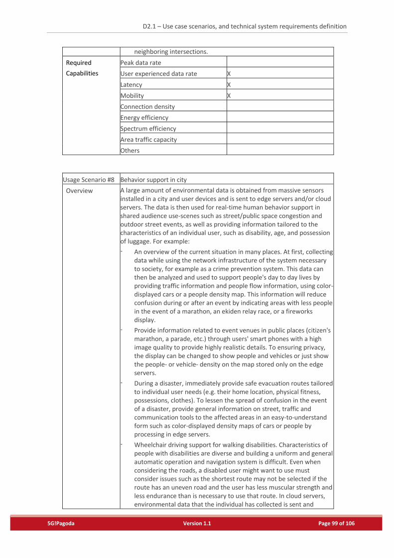
D2.1 – Use case scenarios, and technical system requirements definition
5G!Pagoda Version 1.1 Page 99 of 106
neighboring intersections.
Required
Capabilities
Peak data rate
User experienced data rate X
Latency X
Mobility X
Connection density
Energy efficiency
Spectrum efficiency
Area traffic capacity
Others
Usage Scenario #8 Behavior support in city
Overview A large amount of environmental data is obtained from massive sensors installed in a city and user devices and is sent to edge servers and/or cloud servers. The data is then used for real-time human behavior support in shared audience use-scenes such as street/public space congestion and outdoor street events, as well as providing information tailored to the characteristics of an individual user, such as disability, age, and possession of luggage. For example:
- An overview of the current situation in many places. At first, collecting data while using the network infrastructure of the system necessary to society, for example as a crime prevention system. This data can then be analyzed and used to support people's day to day lives by providing traffic information and people flow information, using color-displayed cars or a people density map. This information will reduce confusion during or after an event by indicating areas with less people in the event of a marathon, an ekiden relay race, or a fireworks display.
- Provide information related to event venues in public places (citizen's marathon, a parade, etc.) through users' smart phones with a high image quality to provide highly realistic details. To ensuring privacy, the display can be changed to show people and vehicles or just show the people- or vehicle- density on the map stored only on the edge servers.
- During a disaster, immediately provide safe evacuation routes tailored to individual user needs (e.g. their home location, physical fitness, possessions, clothes). To lessen the spread of confusion in the event of a disaster, provide general information on street, traffic and communication tools to the affected areas in an easy-to-understand form such as color-displayed density maps of cars or people by processing in edge servers.
- Wheelchair driving support for walking disabilities. Characteristics of people with disabilities are diverse and building a uniform and general automatic operation and navigation system is difficult. Even when considering the roads, a disabled user might want to use must consider issues such as the shortest route may not be selected if the route has an uneven road and the user has less muscular strength and less endurance than is necessary to use that route. In cloud servers, environmental data that the individual has collected is sent and
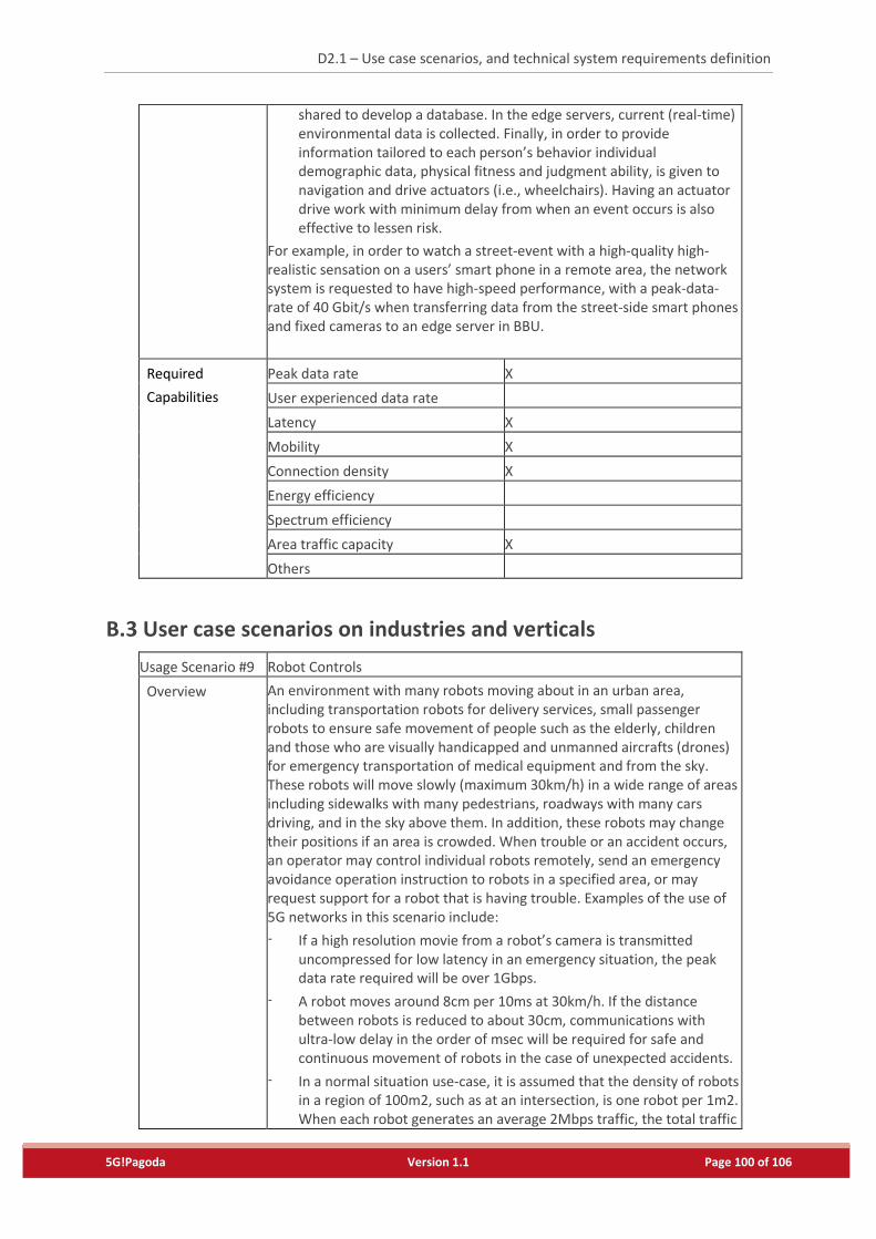
D2.1 – Use case scenarios, and technical system requirements definition
5G!Pagoda Version 1.1 Page 100 of 106
shared to develop a database. In the edge servers, current (real-time) environmental data is collected. Finally, in order to provide information tailored to each person’s behavior individual demographic data, physical fitness and judgment ability, is given to navigation and drive actuators (i.e., wheelchairs). Having an actuator drive work with minimum delay from when an event occurs is also effective to lessen risk.
For example, in order to watch a street-event with a high-quality high-realistic sensation on a users’ smart phone in a remote area, the network system is requested to have high-speed performance, with a peak-data-rate of 40 Gbit/s when transferring data from the street-side smart phones and fixed cameras to an edge server in BBU.
Required
Capabilities
Peak data rate X
User experienced data rate
Latency X
Mobility X
Connection density X
Energy efficiency
Spectrum efficiency
Area traffic capacity X
Others
B.3 User case scenarios on industries and verticals
Usage Scenario #9 Robot Controls
Overview An environment with many robots moving about in an urban area, including transportation robots for delivery services, small passenger robots to ensure safe movement of people such as the elderly, children and those who are visually handicapped and unmanned aircrafts (drones) for emergency transportation of medical equipment and from the sky. These robots will move slowly (maximum 30km/h) in a wide range of areas including sidewalks with many pedestrians, roadways with many cars driving, and in the sky above them. In addition, these robots may change their positions if an area is crowded. When trouble or an accident occurs, an operator may control individual robots remotely, send an emergency avoidance operation instruction to robots in a specified area, or may request support for a robot that is having trouble. Examples of the use of 5G networks in this scenario include:
- If a high resolution movie from a robot’s camera is transmitted uncompressed for low latency in an emergency situation, the peak data rate required will be over 1Gbps.
- A robot moves around 8cm per 10ms at 30km/h. If the distance between robots is reduced to about 30cm, communications with ultra-low delay in the order of msec will be required for safe and continuous movement of robots in the case of unexpected accidents.
- In a normal situation use-case, it is assumed that the density of robots in a region of 100m2, such as at an intersection, is one robot per 1m2. When each robot generates an average 2Mbps traffic, the total traffic
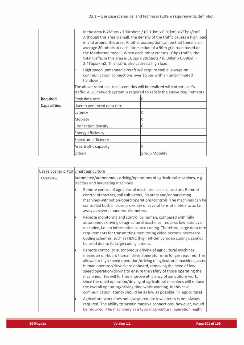
D2.1 – Use case scenarios, and technical system requirements definition
5G!Pagoda Version 1.1 Page 101 of 106
in the area is 2Mbps x 100robots / (0.01km x 0.01km) = 2Tbps/km2. Although this area is small, the density of the traffic causes a high load in and around this area. Another assumption can be that there is an average 20 robots at each intersection of a 90m grid road based on the Manhattan model. When each robot creates 1Gbps traffic, the total traffic in this area is 1Gbps x 20robots / (0.09km x 0.09km) = 2.4Tbps/km2. This traffic also causes a high load.
- High speed unmanned aircraft will require stable, always-on communication connections over 1Gbps with an unterminated handover.
The above robot use-case scenarios will be realized with other user’s traffic. A 5G network system is required to satisfy the above requirements.
Required
Capabilities
Peak data rate X
User experienced data rate
Latency X
Mobility X
Connection density X
Energy efficiency
Spectrum efficiency
Area traffic capacity X
Others Group Mobility
Usage Scenario #10 Smart agriculture
Overview Automated/autonomous driving/operations of agricultural machines, e.g. tractors and harvesting machines
Remote control of agricultural machines, such as tractors. Remote control of tractors, soil cultivators, planters and/or harvesting machines without on-board operations/controls. The machines can be controlled both in close proximity of several tens of meters to as far away as several hundred kilometers.
Remote monitoring and control by human, compared with fully autonomous driving of agricultural machines, requires low-latency or no codec, i.e. no information source coding. Therefore, large data rate requirements for transmitting monitoring video become necessary. Coding schemes, such as HEVC (high efficiency video coding), cannot be used due to its large coding latency.
Remote control or autonomous driving of agricultural machines means an on-board human driver/operator is no longer required. This allows for high speed operation/driving of agricultural machines, as no human operator/drivers are onboard, removing the need of low speed operation/driving to ensure the safety of those operating the machines. This will further improve efficiency of agriculture work, since the rapid operation/driving of agricultural machines will reduce the overall operating/driving time while working. In this case, communication latency should be as low as possible. [IT agriculture]
Agriculture work does not always require low latency is not always required. The ability to sustain massive connections, however, would be required. The machinery at a typical agricultural operation might
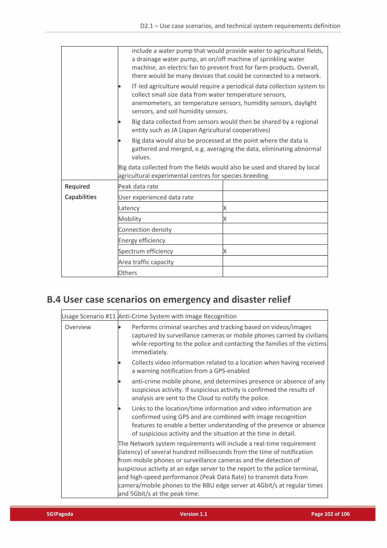
D2.1 – Use case scenarios, and technical system requirements definition
5G!Pagoda Version 1.1 Page 102 of 106
include a water pump that would provide water to agricultural fields, a drainage water pump, an on/off machine of sprinkling water machine, an electric fan to prevent frost for farm products. Overall, there would be many devices that could be connected to a network.
IT-led agriculture would require a periodical data collection system to collect small size data from water temperature sensors, anemometers, air temperature sensors, humidity sensors, daylight sensors, and soil humidity sensors.
Big data collected from sensors would then be shared by a regional entity such as JA (Japan Agricultural cooperatives)
Big data would also be processed at the point where the data is gathered and merged, e.g. averaging the data, eliminating abnormal values.
Big data collected from the fields would also be used and shared by local agricultural experimental centres for species breeding.
Required
Capabilities
Peak data rate
User experienced data rate
Latency X
Mobility X
Connection density
Energy efficiency
Spectrum efficiency X
Area traffic capacity
Others
B.4 User case scenarios on emergency and disaster relief
Usage Scenario #11 Anti-Crime System with Image Recognition
Overview Performs criminal searches and tracking based on videos/images captured by surveillance cameras or mobile phones carried by civilians while reporting to the police and contacting the families of the victims immediately.
Collects video information related to a location when having received a warning notification from a GPS-enabled
anti-crime mobile phone, and determines presence or absence of any suspicious activity. If suspicious activity is confirmed the results of analysis are sent to the Cloud to notify the police.
Links to the location/time information and video information are confirmed using GPS and are combined with image recognition features to enable a better understanding of the presence or absence of suspicious activity and the situation at the time in detail.
The Network system requirements will include a real-time requirement (latency) of several hundred milliseconds from the time of notification from mobile phones or surveillance cameras and the detection of suspicious activity at an edge server to the report to the police terminal, and high-speed performance (Peak Data Rate) to transmit data from camera/mobile phones to the BBU edge server at 4Gbit/s at regular times and 5Gbit/s at the peak time.
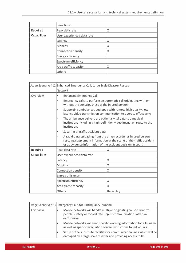
D2.1 – Use case scenarios, and technical system requirements definition
5G!Pagoda Version 1.1 Page 103 of 106
peak time.
Required
Capabilities
Peak data rate X
User experienced data rate
Latency X
Mobility X
Connection density X
Energy efficiency
Spectrum efficiency
Area traffic capacity X
Others
Usage Scenario #12 Enhanced Emergency Call, Large Scale Disaster Rescue
Network
Overview Enhanced Emergency Call
- Emergency calls to perform an automatic call originating with or without the consciousness of the injured person;
- Supporting ambulances equipped with remote high quality, low latency video transmission communication to operate effectively;
- The ambulance delivers the patient's vital data to a medical institution, including a high-definition video image, en route to the institution.
Securing of traffic accident data
- A rapid data uploading from the drive recorder as injured person rescuing supplement information at the scene of the traffic accident or as evidence information of the accident decision in court.
Required
Capabilities
Peak data rate X
User experienced data rate
Latency X
Mobility X
Connection density X
Energy efficiency
Spectrum efficiency X
Area traffic capacity X
Others Reliability
Usage Scenario #13 Emergency Calls for Earthquake/Tsunami
Overview Mobile networks will handle multiple originating calls to confirm people's safety or to facilitate urgent communications after an earthquake;
Mobile networks will send specific warning information for a tsunami as well as specific evacuation course instructions to individuals;
Setup of the substitute facilities for communication lines which will be damaged by a large-scale disaster and providing access to IP
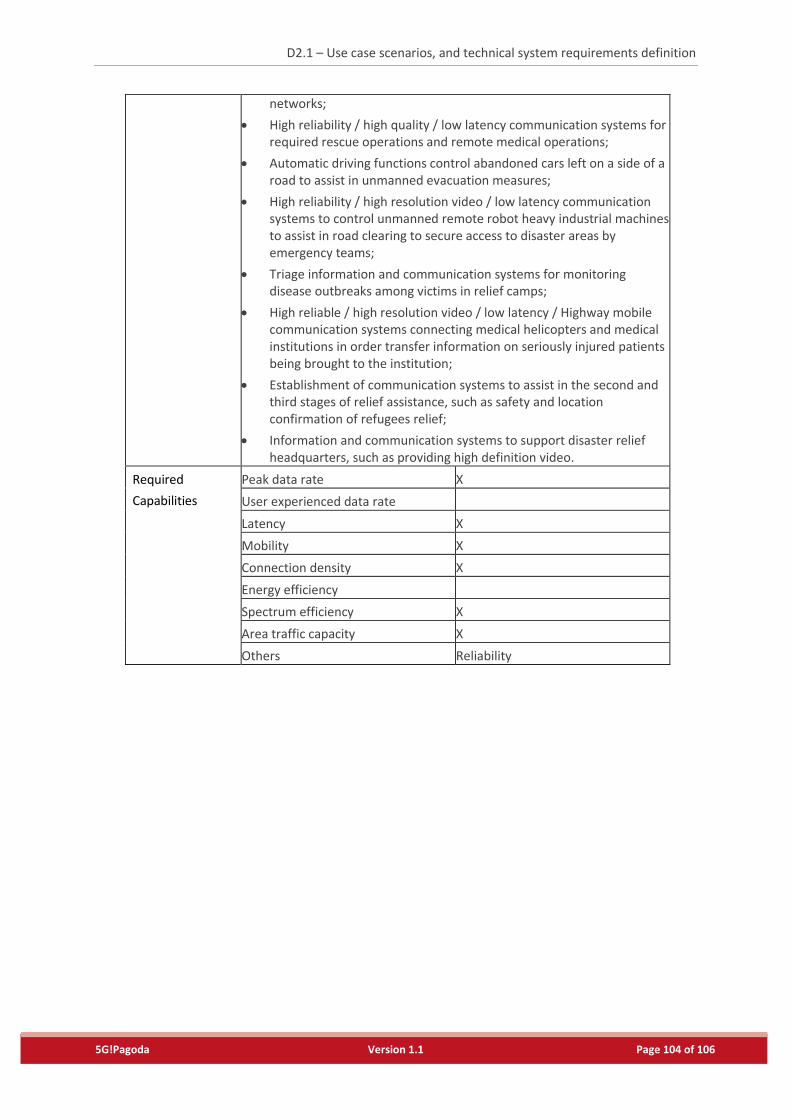
D2.1 – Use case scenarios, and technical system requirements definition
5G!Pagoda Version 1.1 Page 104 of 106
networks;
High reliability / high quality / low latency communication systems for required rescue operations and remote medical operations;
Automatic driving functions control abandoned cars left on a side of a road to assist in unmanned evacuation measures;
High reliability / high resolution video / low latency communication systems to control unmanned remote robot heavy industrial machines to assist in road clearing to secure access to disaster areas by emergency teams;
Triage information and communication systems for monitoring disease outbreaks among victims in relief camps;
High reliable / high resolution video / low latency / Highway mobile communication systems connecting medical helicopters and medical institutions in order transfer information on seriously injured patients being brought to the institution;
Establishment of communication systems to assist in the second and third stages of relief assistance, such as safety and location confirmation of refugees relief;
Information and communication systems to support disaster relief headquarters, such as providing high definition video.
Required
Capabilities
Peak data rate X
User experienced data rate
Latency X
Mobility X
Connection density X
Energy efficiency
Spectrum efficiency X
Area traffic capacity X
Others Reliability
D2.1 – Use case scenarios, and technical system requirements definition
5G!Pagoda Version 1.1 Page 105 of 106
References
[1] A. Nakao et. al., “Deliverable of Network softwarization for IMT-2020 Networks,” ITU-T IMT-I-096r1,
Network Softwarization Focus Group on IMT-2020, Oct. 2015.
[2] Y. Jin et. al, “Characterizing Data Usage Patterns in a Large Cellular Network,” in Proc. SIGCOMM CellNet
Workshop, Helsinki, Finland, Aug. 2012.
[3] Y. Zhang and A. Arvidsson, “Understanding the Characteristics of Cellular Data Traffic,” in Proc. SIGCOMM
CellNet Workshop, Helsinki, Finland, Aug. 2012.
[4] K. Ashton, “That 'Internet of Things' Thing” in RFID journal, Jun. 2009
[5] “Internet of Things Global Standards Initiative”, ITU-T, http://www.itu.int/en/ITU-
T/gsi/iot/Pages/default.aspx
[6] “Study on New Services and Markets Technology Enablers,” the 3rd partnership project (3GPP), TR
22.891, version 14.2.0, Sep. 2016
[7] “MGMN 5G WHITE PAPER,”, NGMN Alliance, white paper,
https://www.ngmn.org/uploads/media/NGMN_5G_White_Paper_V1_0.pdf, Feb. 2015.
[8] “Deliverable D2.1: Use cases, scenario and requirements,”, 5GPPP, Project: H2020-ICT-2014-2 5G NORMA,
https://5gnorma.5g-ppp.eu/wp-content/uploads/2015/11/5G-NORMA_D2.1.pdf, October 2015.
[9] FANTASTIC-5G, http://fantastic5g.eu/
[10] METIS-II Project, https://5g-ppp.eu/metis-ii/
[11] "5G PPP use cases and performance evaluation models," the 5G Initiative, white paper, https://5g-
ppp.eu/wp-content/uploads/2014/02/5G-PPP-use-cases-and-performance-evaluation-
modeling_v1.0.pdf
[12] “5G PPP 5G Architecture,” the 5G PPP Architecture working Group, white paper, https://5g-ppp.eu/wp-
content/uploads/2014/02/5G-PPP-5G-Architecture-WP-July-2016.pdf
[13] “5G Mobile Communications Systems for 2020 and beyond,” the 5th Generation Mobile
Communications Promotion Forum (5GMF), white paper, http://5gmf.jp/wp/wp-
content/uploads/2016/07/5GMF_WP100_Executive_Summary-E.pdf, July 2016.
[14] Kengo Sasaki, Naoya Suzuki, Satoshi Makido, Akihiro Nakao, “Vehicle Control System Coordinated
between Cloud and Mobile Edge Computing”, IEEE SICE Annual Conference 2016, Sept 2016
[15] The Third Generation Partnership Project, last visited on 29.11.2016, http://www.3gpp.org/;
[16] Akihiro Nakao, “Network virtualization as foundation for enabling new network architectures and
applications,” IEICE transactions on communications, vol. 93, no. 3, pp. 454–457, 2010.
[17] ISO FCAPS standard, last visited on 29.11.2016,
http://standards.iso.org/ittf/PubliclyAvailableStandards/s014258_ISO_IEC_7498-4_1989(E).zip;
[18] “Flare: Open deeply programmable network node architecture,”
http://netseminar.stanford.edu/seminars/10 18 12.pdf.
[19] International Telecomunication Unit, last visite don 29.11.2016, https://www.itu.int/;
[20] IEV operations and maintenance definitions for operations, maintenance support and maintenance, last
visited on 29.11.2016, http://www.electropedia.org/;
[21] “Planetlab,” http://www.planet-lab.org, 2012.
[22] 5G, (Nov. 30, 2016, 14:35 UTC). In Wikipedia: The Free Encyclopedia. Retrieved from
https://en.wikipedia.org/wiki/5G
[23] Business to business to consumer, (Nov. 30, 2016, 14:40 UTC). In techopedia. Retrieved from
https://www.techopedia.com/definition/23169/business-to-business-to-consumer-b2b2c
[24] Cloud computing, (Nov. 30, 2016, 14:42 UTC). In Wikipedia: The Free Encyclopedia. Retrieved from
https://en.wikipedia.org/wiki/Cloud_computing
[25] Software-Defined Networking, (Nov. 30, 2016, 14:44 UTC). In Wikipedia: The Free Encyclopedia.
Retrieved from https://en.wikipedia.org/wiki/Software-defined_networking
D2.1 – Use case scenarios, and technical system requirements definition
5G!Pagoda Version 1.1 Page 106 of 106
[26] Network function virtualization, (Nov. 30, 2016, 14:47 UTC). In Wikipedia: The Free Encyclopedia.
Retrieved from https://en.wikipedia.org/wiki/Network_function_virtualization
[27] Working Party 5D (WP 5D) – IMT System, (Nov. 30, 2016, 15:03 UTC). In ITU. Retrieved from
http://www.itu.int/en/ITU-R/study-groups/rsg5/rwp5d/Pages/default.aspx
[28] Focus group on IMT-2020, (Nov. 30, 2016, 15:10 UTC). In ITU. Retrieved from http://www.itu.int/en/ITU-
T/focusgroups/imt-2020/Pages/default.aspx
[29] 3GPP, (Nov. 30, 2016, 15:11 UTC). Retrieved from http://www.3gpp.org/
[30] 5GMF, (Nov. 30, 2016, 15:07 UTC). Retrieved from http://5gmf.jp/en/
[31] Content delivery network, (Nov. 30, 2016, 15:11 UTC). In Wikipedia: The Free Encyclopedia. Retrieved
from https://en.wikipedia.org/wiki/Content_delivery_network
[32] Mobile Edge Computing, (Nov. 30, 2016, 15:13 UTC). In Wikipedia: The Free Encyclopedia. Retrieved from
https://en.wikipedia.org/wiki/Mobile_edge_computing
[33] Quality of experience, (Nov. 30, 2016, 15:14 UTC). In Wikipedia: The Free Encyclopedia. Retrieved from
https://en.wikipedia.org/wiki/Quality_of_experience
[34] Akihiro Nakao, Ping Du, Yoshiaki Kiriha, Tarik Taleb, et.al., “Network Slicing for 5G Mobile Networking”
IPSJ 2016 (to appear)
[35] P. Frangoudis, L. Yala, A. Ksentini, and T. Taleb, “An architecture for on-demand service deployment over
a telco CDN,” in IEEE ICC’16, Kuala Lumpur, Malaysia, May 2016.
[36] T. Taleb, S. Dutta, A. Ksentini, I. Muddesar, and H. Flinck "Mobile Edge Computing Potential in Making
Cities Smarter," to appear in IEEE Communications Magazine.
[37] S. Dutta, T. Taleb, P. A. Frangoudis, and A. Ksentini, "On-the-fly QoE-Aware Transcoding in the Mobile
Edge,” in Proc. IEEE Globecom 2016, Washington, USA, Dec. 2016.
[38] S. Dutta, T. Taleb, and A. Ksentini, “QoE-aware Elasticity Support in Cloud-Native 5G Systems,” in IEEE
ICC’16, Kuala Lumpur, Malaysia, May 2016.


![SESAR 2020 - 763601 - D2.1 - Scenarios and Requirements · SESAR 2020 - 763601 - D2.1 - Scenarios and Requirements DeliverableID [D2.1] ProjectAcronym DroC2om Grant: 763601 Call:](https://img.pdfslide.net/doc/110x75/603a54b6ac67ff69d9242d39/sesar-2020-763601-d21-scenarios-and-requirements-sesar-2020-763601-d21.jpg)