Embed Size (px)
Citation preview
D2.2
Report on analysis of ‘functional distribution architecture’ frameworks and solutions
Project number: 730830
Project acronym: Safe4RAIL
Project title: Safe4RAIL: SAFE architecture for Robust distributed Application Integration in roLling stock
Start date of the project: 1st October, 2016
Duration: 24 months
Programme: H2020-S2RJU-OC-2016-01-2
Deliverable type: Report
Deliverable reference number: ICT-730830 / D2.2/ FINAL | 1.0
Work package WP 2
Due date: April 2017 – M07
Actual submission date: 29th April 2017
Responsible organisation: SIE
Editor: Hongjie Fang
Dissemination level: Public
Revision: FINAL | 1.0
Abstract:
Analyses functional distribution architecture frameworks and solutions, identifies the gaps between COTS frameworks/solutions and the next generation TCMS.
Keywords: Functional distribution architecture, AUTOSAR, ARINC 653, TCMS, RTOS, Hypervisor
This project has received funding from the Shift2Rail Joint Undertaking under grant agreement No 730830. This Joint Undertaking receives support from the European Union’s Horizon 2020 research and innovation programme and Austria, Spain, Germany, Czech Republic, Italy, France.
D2.2 – Report on analysis of ‘functional distribution architecture’ frameworks and solutions
Editor
Hongjie Fang (SIE)
Contributors (ordered according to beneficiary numbers)
Derya Mete Saatci, Arjan Geven (TTT)
Iñigo Odriozola, Ekain Azketa (IKL)
Hongjie Fang (SIE)
Petr Novobilsky (UNI)
Bernd Löhr, Iris Bosse (NEW)
Youlian Kirov (IAV)
Disclaimer
The information in this document is provided “as is”, and no guarantee or warranty is given that the information is fit for any particular purpose. The content of this document reflects only the author`s view – the European Commission is not responsible for any use that may be made of the information it contains. The users use the information at their sole risk and liability.
D2.2 – Report on analysis of ‘functional distribution architecture’ frameworks and solutions
Executive Summary
The main task of WP2 of Safe4RAIL is to provide the “Functional Distribution” architecture concept for a mixed criticality embedded platform, offering an execution environment for multiple Train Control and Monitoring System (TCMS) application functions with a virtual bus inside the end-system.
This document aims at providing a detailed comparative analysis of cross-industry ‘functional distribution architecture’ frameworks and solutions, based on the State Of The Art (SOTA) analysis of “Functional distribution” architecture frameworks and embedded platform solutions as well as high level requirements of the next generation TCMS in D2.1. This analysis takes into consideration domain specific standardized framework (AUTOSAR, ARINC 653, TCN application profiles) and Commercial Off The Shelf (COTS) solutions (RTOS, hypervisor) which are likely to be used for the development of the to be designed framework.
This deliverable will be organized in this way: Chapter 2 analyses the existing COTS solutions (RTOS and hypervisor) that are likely to be used for the framework ; Chapter 3 analyses the SOTA of Automotive Open System Architecture (AUTOSAR) standard of automotive domain and identifies the gap between AUTOSAR and the high level requirements of next generation TCMS, as well as Chapter 4 concentrates on the avionic domain by analysing SOTA of ARINC 653 standard, Chapter 5 focuses on the TCN standard; In the 0, a comparative summary of the domain specific aspects will be done.
D2.2 – Report on analysis of ‘functional distribution architecture’ frameworks and solutions
Contents
Executive Summary ................................. ................................................................ 3
Contents .......................................... .......................................................................... 4
List of Figures ................................... ........................................................................ 8
List of Tables .................................... ........................................................................ 9
Chapter 1 Introduction ...................................... ................................................. 10
1.1 Description of Safe4RAIL ............................................................................... 10
1.2 Mixed criticality application framework ........................................................... 11
Chapter 2 Analysis of RTOS and Hypervisor ................... ................................ 13
2.1 PikeOS ........................................................................................................... 13
2.1.1 CPU scheduling strategy .......................................................................................13
2.1.2 Memory management ...........................................................................................13
2.1.2.1 Memory allocation .........................................................................................13
2.1.2.2 Memory access control..................................................................................14
2.1.3 Safety support .......................................................................................................14
2.1.4 Fault tolerant .........................................................................................................14
2.1.5 Compatible characteristic ......................................................................................15
2.2 XtratuM .......................................................................................................... 15
2.2.1 CPU scheduling strategy .......................................................................................15
2.2.2 Memory management ...........................................................................................15
2.2.2.1 Memory allocation .........................................................................................15
2.2.2.2 Memory access control..................................................................................16
2.2.3 Safety support .......................................................................................................16
2.2.4 Fault tolerant .........................................................................................................16
2.2.5 Compatible characteristic ......................................................................................17
2.3 VxWorks ........................................................................................................ 17
2.3.1 CPU scheduling strategy .......................................................................................17
2.3.2 Memory management ...........................................................................................18
2.3.2.1 Memory allocation .........................................................................................18
2.3.2.2 Memory access control..................................................................................18
2.3.3 Safety support .......................................................................................................18
2.3.4 Fault tolerant .........................................................................................................18
2.3.5 Compatible characteristic ......................................................................................19

D2.2 – Report on analysis of ‘functional distribution architecture’ frameworks and solutions
2.4 LynxOS .......................................................................................................... 19
2.4.1 CPU scheduling strategy .......................................................................................19
2.4.2 Memory management ...........................................................................................19
2.4.2.1 Memory allocation .........................................................................................19
2.4.2.2 Memory access control..................................................................................19
2.4.3 Safety support .......................................................................................................19
2.4.4 Fault tolerant .........................................................................................................20
2.4.5 Compatible characteristic ......................................................................................20
2.5 Integrity .......................................................................................................... 20
2.5.1 CPU scheduling strategy .......................................................................................20
2.5.2 Memory management ...........................................................................................20
2.5.2.1 Memory allocation .........................................................................................20
2.5.2.2 Memory access control..................................................................................21
2.5.3 Safety support .......................................................................................................21
2.5.4 Fault tolerant .........................................................................................................21
2.5.5 Compatible characteristic ......................................................................................21
2.6 Comparative conclusion ................................................................................. 21
Chapter 3 Comparative analysis of AUTOSAR ................... ............................. 23
3.1 Technical characteristics ................................................................................ 23
3.1.1 Configuration and management services ..............................................................23
3.1.1.1 Management services ...................................................................................23
3.1.1.2 Partition management ...................................................................................23
3.1.1.3 Process management ...................................................................................24
3.1.1.4 Time management ........................................................................................24
3.1.1.5 Memory management ...................................................................................24
3.1.1.6 Communication management ........................................................................25
3.1.2 Time services ........................................................................................................25
3.1.3 Input/Output Services ............................................................................................25
3.1.4 Real-time support ..................................................................................................25
3.1.5 Fault isolation ........................................................................................................26
3.1.6 Health monitoring ..................................................................................................26
3.1.7 Security services ...................................................................................................26
3.1.8 Requirements for underlying platform ...................................................................26
3.2 Non-technical characteristics ......................................................................... 27
3.2.1 System Architecture Engineering Method .............................................................27
3.2.2 Safety and the relevant standards .........................................................................27
3.2.3 Security and the relevant standards ......................................................................28

D2.2 – Report on analysis of ‘functional distribution architecture’ frameworks and solutions
Chapter 4 Comparative analysis of ARINC 653 ................. ............................... 29
4.1 Technical characteristics ................................................................................ 29
4.1.1 Configuration and management services ..............................................................29
4.1.1.1 Configuration services ...................................................................................29
4.1.1.2 Management services ...................................................................................30
4.1.1.2.1 Partition management ............................................................................................ 30
4.1.1.2.2 Process management ............................................................................................ 30
4.1.1.2.3 Memory management ............................................................................................ 30
4.1.2 Time services ........................................................................................................30
4.1.3 Input/Output Services ............................................................................................31
4.1.4 Real-time support ..................................................................................................31
4.1.5 Fault isolation ........................................................................................................31
4.1.6 Health monitoring ..................................................................................................32
4.1.7 Security services ...................................................................................................32
4.1.8 Requirements for underlying platform ...................................................................33
4.2 Non-technical characteristics ......................................................................... 33
4.2.1 System Architecture Engineering Method .............................................................33
4.2.2 Safety and the relevant standards .........................................................................34
4.2.3 Security and the relevant standards ......................................................................35
Chapter 5 Comparative analysis of existing TCMSs ............ ........................... 36
5.1 Technical characteristics ................................................................................ 36
5.1.1 Configuration and management services ..............................................................36
5.1.1.1 Configuration services ...................................................................................36
5.1.1.2 Management services ...................................................................................37
5.1.2 Time services ........................................................................................................37
5.1.3 Input/Output Services ............................................................................................37
5.1.4 Real-time support ..................................................................................................38
5.1.5 Fault isolation ........................................................................................................38
5.1.6 Health monitoring ..................................................................................................38
5.1.7 Security services ...................................................................................................38
5.1.8 Requirements for underlying platform ...................................................................39
5.1.9 Safety Services .....................................................................................................39
5.2 Non-technical characteristics ......................................................................... 40
5.2.1 System Architecture Engineering Method .............................................................40
5.2.2 Safety and the relevant standards .........................................................................40
5.2.3 Security and the relevant standards ......................................................................40
Chapter 6 Summary and conclusion ............................ ..................................... 41
D2.2 – Report on analysis of ‘functional distribution architecture’ frameworks and solutions
Chapter 7 List of Abbreviations ............................. ........................................... 43
Chapter 8 Bibliography ...................................... ................................................ 46
Annex 1 – ARINC 653 Analysis to EN50128 ........... .............................................. 49
Annex 2 – AUTOSAR Analysis to EN50128 ............. ............................................. 56
Annex 3 – AUTOSAR Analysis to IEC62443 ............ ............................................. 65

D2.2 – Report on analysis of ‘functional distribution architecture’ frameworks and solutions
List of Figures
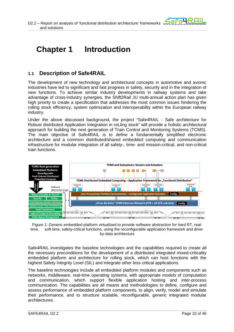
Figure 1: Generic embedded platform virtualized to provide software abstraction for hard RT, real-time, soft-time, safety-critical functions, using the reconfigurable application framework and drive-by-data architecture .....................................................................10
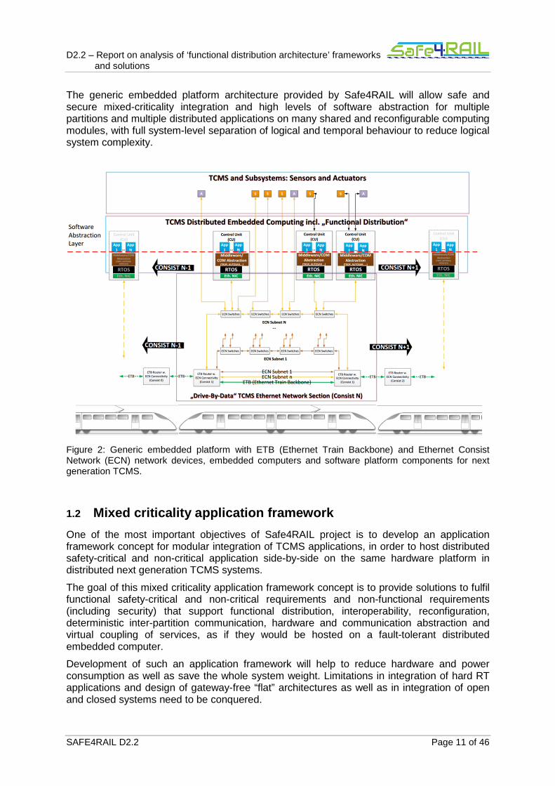
Figure 2: Generic embedded platform with ETB (Ethernet Train Backbone) and Ethernet Consist Network (ECN) network devices, embedded computers and software platform components for next generation TCMS. ........................................................................11
D2.2 – Report on analysis of ‘functional distribution architecture’ frameworks and solutions
List of Tables
Table 1: Device Configuration ..............................................................................................37
Table 2: TCMS Needed Resources ......................................................................................39
Table 3: List of Abbreviations ...............................................................................................45
D2.2 – Report on analysis of ‘functional distribution architecture’ frameworks and solutions
SAFE4RAIL D2.2 Page 10 of 46
Chapter 1 Introduction
1.1 Description of Safe4RAIL
The development of new technology and architectural concepts in automotive and avionic industries have led to significant and fast progress in safety, security and in the integration of new functions. To achieve similar industry developments in railway systems and take advantage of cross-industry synergies, the Shift2Rail JU multi-annual action plan has given high priority to create a specification that addresses the most common issues hindering the rolling stock efficiency, system optimization and interoperability within the European railway industry.
Under the above discussed background, the project “Safe4RAIL - Safe architecture for Robust distributed Application Integration in roLling stock” will provide a holistic architectural approach for building the next generation of Train Control and Monitoring Systems (TCMS). The main objective of Safe4RAIL is to define a fundamentally simplified electronic architecture and a common distributed/shared embedded computing and communication infrastructure for modular integration of all safety-, time- and mission-critical, and non-critical train functions.
Figure 1: Generic embedded platform virtualized to provide software abstraction for hard RT, real-
time, soft-time, safety-critical functions, using the reconfigurable application framework and drive-by-data architecture
Safe4RAIL investigates the baseline technologies and the capabilities required to create all the necessary preconditions for the development of a distributed integrated mixed-criticality embedded platform and architecture for rolling stock, which can host functions with the highest Safety Integrity Level (SIL) and integrate other less critical applications.
The baseline technologies include all embedded platform modules and components such as networks, middleware, real-time operating systems, with appropriate models of computation and communication, which support flexible application hosting and inter-process communication. The capabilities are all means and methodologies to define, configure and assess performance of embedded platform components, to align, verify, model and simulate their performance, and to structure scalable, reconfigurable, generic integrated modular architectures.
D2.2 – Report on analysis of ‘functional distribution architecture’ frameworks and solutions
SAFE4RAIL D2.2 Page 11 of 46
The generic embedded platform architecture provided by Safe4RAIL will allow safe and secure mixed-criticality integration and high levels of software abstraction for multiple partitions and multiple distributed applications on many shared and reconfigurable computing modules, with full system-level separation of logical and temporal behaviour to reduce logical system complexity.
Figure 2: Generic embedded platform with ETB (Ethernet Train Backbone) and Ethernet Consist Network (ECN) network devices, embedded computers and software platform components for next generation TCMS.
1.2 Mixed criticality application framework
One of the most important objectives of Safe4RAIL project is to develop an application framework concept for modular integration of TCMS applications, in order to host distributed safety-critical and non-critical application side-by-side on the same hardware platform in distributed next generation TCMS systems.
The goal of this mixed criticality application framework concept is to provide solutions to fulfil functional safety-critical and non-critical requirements and non-functional requirements (including security) that support functional distribution, interoperability, reconfiguration, deterministic inter-partition communication, hardware and communication abstraction and virtual coupling of services, as if they would be hosted on a fault-tolerant distributed embedded computer.
Development of such an application framework will help to reduce hardware and power consumption as well as save the whole system weight. Limitations in integration of hard RT applications and design of gateway-free “flat” architectures as well as in integration of open and closed systems need to be conquered.
D2.2 – Report on analysis of ‘functional distribution architecture’ frameworks and solutions
SAFE4RAIL D2.2 Page 12 of 46
System-level partitioning and virtualization with temporal and spatial isolation in mixed criticality systems will be adopted in the design process. Temporal and spatial partitioning will help to simplify system integration and guarantee complete isolation of distributed functions in an integrated system. Only critical computing/networking resources attached to functional distribution, their configured use and interactions are to be certified.
After design of the application framework, the defined concepts and methodologies during the development process need to be proved and the integrated system should be evaluated to reach up to SIL 4 level.
D2.2 – Report on analysis of ‘functional distribution architecture’ frameworks
and solutions
SAFE4RAIL D2.2 Page 13 of 46
Chapter 2 Analysis of RTOS and
Hypervisor
In this chapter, the selected COTS Hypervisors and RTOSs will be analysed with respect to the high level requirements in D2.1 [1], in order to select the potential feasible solution for designing the next generation TCMS framework.
2.1 PikeOS
2.1.1 CPU scheduling strategy
PikeOS is a platform providing RTOS, type 1 hypervisor (enables hardware virtualisation) and para-virtualization functionalities.
- Threads are scheduled based on their priority. - The available Central Processing Unit (CPU) time can be partitioned into time windows
called time partitions. Time partitions can be grouped to a major time frame, which is executed cyclically.
- The scheduling scheme defined by the major time frame can be changed on run-time - In order to allow idle time usage or low latency for exception handling, threads can
always be assigned to a special time-partition 0 (for details see [2]). - The scheduler can be configured to execute certain threads on dedicated processor
cores. - Guest operating systems such as Linux use their own scheduler within the assigned time
window.
2.1.2 Memory management
In PikeOS, the physical memory can be separated in multiple physical memory regions that are in turns used to serve per-partition allocations (including kernel resources e.g., thread/task descriptors). This effectively allows per-partition allocations to be not only virtually separated, but also physically separated. Physical memory partitioning may be useful to e.g., ensure that partitions will be always served by one memory controller, or that specific physically tagged cache entries are not evicted, or simply to ensure a higher predictability in the per-partition memory access.
2.1.2.1 Memory allocation
In order to comply with safety standards, in PikeOS, the memory for each partition is assigned statically. The different memory types defined by PikeOS are:
- VM_MEM_TYPE_RAM memory requirement describes a memory resource consisting of system RAM pages that shall be allocated and assigned to the partition.
- VM_MEM_TYPE_ROM specifies an area within a Read Only Memory (ROM) segment, which shall be accessible by the partition.

D2.2 – Report on analysis of ‘functional distribution architecture’ frameworks
and solutions
SAFE4RAIL D2.2 Page 14 of 46
- VM_MEM_TYPE_IO_MEM specifies an area of memory mapped Input/Output (I/O) address space that shall be accessible by the partition
- VM_MEM_TYPE_KMEM tells the PSSW (PikeOS System Software) how much memory (given in bytes) shall be allocated for the partition’s kernel resources.
The PikeOS extension for a native application implements a malloc and free, to be used within the C library CLIB. A contiguous memory pool has to be statically assigned upfront. After mapping a part of this pool into the user-space malloc can use this memory.
2.1.2.2 Memory access control
PikeOS requires definitely a hardware Memory Management Unit (MMU) to perform its separation capabilities. Each partition has its own virtual memory space and within a partition every task has its own virtual memory space. The memory assignment is done statically within the integration project and cannot be altered later on.
2.1.3 Safety support
PikeOS is a foundation for safety requirement of smart devices. It provides a hypervisor on top of a micro kernel allowing the separation of diverse applications into different partitions [3]. According to [3], PikeOS has received the first SIL 4 certification according to EN 50128 [4] on a multi-core platform.
Only the micro-kernel of PikeOS runs in privileged mode. All of its code contributes to the trusted code base of every application within the system that might run on top of it. This mechanism can reduce the cost of code certification and even allow the combination of applications of different levels of criticality since every application can be certified (e.g. based on EN 50128 [4]) independently from others [3]. Mix-criticality within a framework can be supported, when such framework is based on PikeOS.
In order to reduce software complexity, PikeOS is equipped with ARINC 653 [5] compliant resource partitioning. In this way, programs running in separate partitions cannot interfere with each other and they do not need to trust each other [3]. Individual criticality levels can also be assigned to each program independently.
2.1.4 Fault tolerant
A PikeOS based system offers three architectural mechanisms to implement as support a fault tolerant design.
- The PikeOS health monitoring system (HM) is designed to handle errors at system runtime and to execute recovery actions as configured by the integrator. Depending on the result of the error-evaluation performed by the HM decision logic, an error could be handled at user level, at partition level, or at module level, thus originating a module global action, which normally result in a system reboot or shutdown.
- Build in tests (BIT) are an integral part of the fault tolerance of a safety system. BITs are always specific to the hardware architecture and for the system architecture. BIT implementation can be implemented into Board Support Package (BSP)
- Software diversity can help to address soft errors. Soft errors could be addressed as well as systematic errors in the software design.

D2.2 – Report on analysis of ‘functional distribution architecture’ frameworks
and solutions
SAFE4RAIL D2.2 Page 15 of 46
2.1.5 Compatible characteristic
PikeOS is a real-time operating system and virtualization platform providing full separation in both time and space for multiple software applications running on different criticality levels [6]. Based on the implemented mechanism, PikeOS is ARINC 653 [5] and AUTOSAR [7] compliant. PikeOS supports also multi-core platforms.
PikeOS uses a scheduler combining time-driven and priority-driven scheduling, which aims at improving the CPU usage comparing to a conventional RTOS. At the development process, the developed Eclipse based Integrated Development Environment (IDE) CODEO [8] supports system architects with graphical configuration tool. CODEO also provides all the components software engineers need to develop embedded applications and includes comprehensive help files to finish embedded projects in a time-saving and cost-efficient way.
PikeOS provides a built-in Health Monitoring Function which implements all features described in the ARINC 653 standard [8]. At the same time, for each of the supported CPU families, a corresponding CPU emulator is available, which makes the application development possible, even before the real hardware is available.
2.2 XtratuM
2.2.1 CPU scheduling strategy
XtratuM is an open-source, bare-metal hypervisor [9] targeting real-time systems and implementing the para-virtualization principle:
- Strong temporal isolation: fixed cyclic scheduler. - Strong spatial isolation: all partitions are executed in processor user mode, and do not
share memory. - Basic resource virtualization: clock and timers, interrupts, memory, CPU and special
devices. - Real-time scheduling policy for partition scheduling. - Efficient context switch for partitions. - Deterministic hypercalls (hypervisor system calls). - Robust and efficient inter-partition communication mechanisms (sampling and queuing
ports). - Low overhead. - Static system definition via configuration file (XML) [9].
2.2.2 Memory management
The XtratuM data structures are static and predefined at build time from the configuration file. The configuration file that contains all the information allocated to each partition as well as specific XtratuM parameters is called XM CF.xml . It contains the information as: memory requirements, processor sharing, peripherals, health monitoring actions, etc.
2.2.2.1 Memory allocation
D2.2 – Report on analysis of ‘functional distribution architecture’ frameworks
and solutions
SAFE4RAIL D2.2 Page 16 of 46
Each partition is in charge of managing the page table. XtratuM is mapped in the top of every memory map. The initial memory map of each partition is built by XtratuM following the description found in the eXtensible Markup Language (XML) configuration file, it cannot be updated by the partition. If a partition requires a new memory map, then it has to define the new memory map by registering a set of pages from its own memory. Once registered, these pages become read-only, so subsequent updates must be validated by XtratuM. Since XM CF.xml defines the resources allocated to each partition, this file represents a contract between the integrator and the partition developers. The integrator or any of the partition developers should not change the contents of the configuration file on their own.
2.2.2.2 Memory access control
Memory space of each application is protected from the rest of the applications present in the system. Partitioned software architecture have evolved to provide such security. The separation kernel establish a combination of hardware and software to allow multiple functions to be performed on a common set of physical resources without interface. Without MMU, all the physical memory is fully accessible. By using this MMU, XtratuM is able to: - Implement full spatial isolation. No partition is longer able to read from memory areas
belonging to other partitions. - Support inter-partition shared memory: two or more partitions are able to share memory
areas (specified in the XML configuration), permitting to design and implement more efficient inter-partition communication mechanisms. And, in addition, code sections could be shared by partitions avoiding duplicity of code.
XtratuM implements
- A new module called virtual memory manager which is in charge of managing the virtual maps, and is able to create/release them and map/unmap physical pages.
- Three new hypercalls: XM_set_page_type() which permits a partition to register new memory maps, XM_update_page32() which allows a partition to update an entry in an already existing memory map, and XM_write_register32(PTD1_REG32,) which enables a partition to change the current memory map with a new one.
2.2.3 Safety support
XtratuM is a hypervisor based on para-virtualization that provides one or more virtual execution environments for partitions. Most importantly, XtratuM was designed to meet safety critical real-time requirements, because it provides strong temporal isolation through fixed cyclic scheduler, as well as strong spatial isolation, which means all partitions don’t share memory between each other at all. More specifically, XtratuM uses its own loader to create a specific memory map for each guest OS to enable memory protection between OSes.
2.2.4 Fault tolerant
The XtratuM health monitor is mechanism proposed by the ARINC specification 653-x to recover or kill partition after a fail has happened [10].

D2.2 – Report on analysis of ‘functional distribution architecture’ frameworks
and solutions
SAFE4RAIL D2.2 Page 17 of 46
The health monitor is the part of XtratuM that detects and reacts to anomalous events or states. The purpose of the HM is to discover the errors at an early stage and try to solve or confine the faulting subsystem in order to avoid or reduce the possible consequences. As result of enforcing the isolation of the partitions, XtratuM contains a lot of consistency and security checks; therefore, it can detect a large number of errors. Errors are grouped by categories. Once an error is detected, XtratuM reacts to the error providing a simple set of predefined actions to be done when it is detected. XtratuM HM subsystem is composed by four logical components: HM event detection : to detect abnormal states, using logical probes in the XtratuM code. HM actions : a set of predefined actions to recover the fault or connect the error. HM configuration : to bind the occurrence of each HM event with the appropriate HM action. HM notification : to report the occurrence of the HM events. Once an HM event is raised, XtratuM performs an action that is specified in the configuration file. Next table shows the list of HM events and the predefined default action at hypervisor and partition level.
2.2.5 Compatible characteristic
XtratuM has been specifically designed for critical real-time systems following the requirements for secure space applications based on the ARINC-653 standard [5]. XtratuM provides ARINC 653 scheduling policy, partition management, inter-partition communications, health monitoring, logbooks, traces, and other services. These can easily be adapted to the ARINC 653 standard. However, it does not provide a compliant Application Program Interface (API) with ARINC 653 standard.
At the moment, XtratuM is not self-hosting, which means, it is necessary to use a cross development system to develop program based on XtratuM. One of the most important characteristics of XtratuM is that it supports for multiprocessor environment.
2.3 VxWorks
2.3.1 CPU scheduling strategy
The VxWorks micro-kernel supports the priority pre-emptive scheduling policy with up to 256 different priority levels and a large number of tasks, and it also supports the round robin scheduling policy [11].
VxWorks offers two different modes for application tasks to execute; either kernel mode or user mode.
- In kernel mode, application-tasks can access the hardware resources directly.
- In user mode, on the other hand, tasks cannot directly access hardware resources, which provides greater protection (e.g., in user mode, tasks cannot crash the kernel).
Kernel mode is provided in all versions of VxWorks while user mode was provided as a part of the Real Time Process (RTP) model, and it has been introduced with VxWorks version 6.0 and beyond.
D2.2 – Report on analysis of ‘functional distribution architecture’ frameworks
and solutions
SAFE4RAIL D2.2 Page 18 of 46
2.3.2 Memory management
2.3.2.1 Memory allocation
VxWorks memory management system does not use swapping or paging. This is because the system allocates memory within the physical address space without the need of swapping data in and out of this space due to memory constraints. VxWorks assumes that there is enough physical memory available to operate its’ kernel and the applications that will run on the operating system. Therefore VxWorks does not have a directly supported virtual memory system.
The amount of memory available to a VxWorks system is dependent upon the platform’s hardware and the memory management unit’s imposed constraints. This amount is usually determined dynamically by the platform depending on how much memory is available, but in some architectures it is a hard coded value. This value is returned by the sysMemTop() method which will set the amount of memory available to the operating system for this session.
2.3.2.2 Memory access control
Memory management unit (MMU)–based memory protection increases reliability. VxWorks incorporates a process-based model that provides user-mode application execution in addition to its traditional kernel-mode execution [11].
2.3.3 Safety support
VxWorks is conformant to the requirements of safety standards such as DO-178C/EUROCAE ED-12C Level A, ARINC 653 [5] and IEC 61508 [12] and it was achieved by partitioning including temporal and spatial partitioning.
For the time partitioning aspect, VxWorks [13] is totally compliant with the ARINC 653 standard. VxWorks 653 also provides an option for priority pre-emptive scheduling of partitions. This method permits slack stealing by allowing designated partitions to consume what would otherwise be idle time in the defined ARINC schedule, in order to raise the processor use rate. In this way, safety critical applications still can finish their job in bounded time.
Spatial partitioning is achieved by using memory protected containers for the partitions that are based on virtual memory contexts [13]. The processor’s MMU is always used to map virtual memory to physical address space, in order to restrict access to the partitioned memory space.
2.3.4 Fault tolerant
The module OS of the VxWorks 653 interacts directly with the computing platform (core module), providing global resource management, scheduling, and health monitoring for each of the partitions. It also uses a BSP, the hardware-specific configuration required to run on different processors and hardware configurations.
D2.2 – Report on analysis of ‘functional distribution architecture’ frameworks
and solutions
SAFE4RAIL D2.2 Page 19 of 46
2.3.5 Compatible characteristic
VxWorks is ARINC 653 compliant and is not a self-hosting OS, so that we need to use a development system across it to develop the applications hosted by it. For the underlying platform, VxWorks supports for multiprocessor.
2.4 LynxOS
2.4.1 CPU scheduling strategy
LynxOS-178 [14] uses fixed cyclic scheduling. Each partition is statically assigned CPU time via a periodically recurring time slice. Thereby, interference between partitions is prevented in the temporal domain.
Within a partition, on the other hand, LynxOS-178 offers a process-based execution environment with priority-based pre-emptive scheduling, priority inheritance, and priority ceilings according to the POSIX model.
2.4.2 Memory management
2.4.2.1 Memory allocation
In analogy to the allocation of the CPU time, Lynx-OS-178 statically performs the allocation of memory to the partitions. The memory allocation of a partition is fixed at design time and the configured memory size cannot be changed at runtime.
2.4.2.2 Memory access control
An MMU is employed for isolating the partitions from each other. In contrast to the memory allocation at the partition level, dynamic memory management is supported within a partition. Therefore, LynxOS-178 offers an API with POSIX-compliant calls. The software layer for establishing this POSIX interface is not part of the LynxOS-178 partitioning kernel, but executed in the partitions.
MMU support has been designed to reside at the lowest level of the kernel of LynxOS. Thus only LynxOS provides real-time capabilities plus the:
- Reliability advantages of protected memory
- Performance advantages of virtual addresses
Where other RTOSs rely on unprotected tasks running in a single flat address space, MMU-based LynxOS enables each task to run protected in its own space.
2.4.3 Safety support
LynxOS can guarantee safety because of the implemented partitioning mechanisms.
The scheduler of LynxOS is pre-emptive and priority based. Which means the current process is pre-empted as soon as a higher priority thread is ready to run. Round-robin,

D2.2 – Report on analysis of ‘functional distribution architecture’ frameworks
and solutions
SAFE4RAIL D2.2 Page 20 of 46
Quantum and FIFO will be used to deal with the situation that the processes have the same priority. Quantum is very similar to round-robin. The only difference is that the length of the time-slice is not fixed, but it is a variable for each priority level. This scheduling mechanism as created to ensure the processing of safety critical processes, in order to guarantee the required safety levels.
MMU must be used for the LynxOS, in order to provide memory protection based on translating the virtual memory into the physical address. LynxOS uses also multiple address spaces, although it could slow down the processing procedure because of a lot of context switching, it can enhance safety of the process. Crash of a single task could be handled by LynxOS.
2.4.4 Fault tolerant
ARINC 653 Health Monitoring: The Health Monitor (HM) is invoked by an application calling the RAISE_APPLICATION_ERROR service or by the OS or hardware detecting a fault.
2.4.5 Compatible characteristic
LynxOS-178 is an ARINC 653 compliant RTOS and it is also UNIX-compatible, POSIX-conforming, multiprocess, and multithreaded operating system designed for complex real- time applications that require fast, deterministic response.
LynxOS is self-hosting, that means the user program can be developed by using the OS as a platform, in order to exclude cross-developing and avoid compatibility problems. At the same time, LynxOS also supports for multiprocessor.
2.5 Integrity
2.5.1 CPU scheduling strategy
The INTEGRITY RTOS [15] can statically bind guest operating systems to cores, in an Asymmetric Multiprocessing (AMP) model, or dynamically schedule workloads in a Symmetric Multiprocessing (SMP) model, depending on system requirements.
2.5.2 Memory management
2.5.2.1 Memory allocation
INTEGRITY’s guaranteed memory resources
• from exhaustion • from damage • from unauthorized access
Unique memory quota system keeps one address space from exhausting the memory of any other.
To prevent kernel memory exhaustion, INTEGRITY requires that kernel memory not be used for messages, semaphores, or other kernel objects created in response to process requests.
D2.2 – Report on analysis of ‘functional distribution architecture’ frameworks
and solutions
SAFE4RAIL D2.2 Page 21 of 46
Instead, the kernel performs all services requested by a process using the memory resources that the requesting process supplies.
To prevent the risk of user stack overflow, INTEGRITY’s kernel has its own memory stack. Without this, the kernel would need to access the user process’ stack. But this can lead to problems because it is impossible for the user process to anticipate the maximum stack size if it is subject to use by unknown code (i.e., the kernel).
2.5.2.2 Memory access control
As one of the first RTOSes to leverage hardware memory-management units (MMUs).
2.5.3 Safety support
INTEGRITY RTOS technology has received a number of certifications and some of them are safety related. For example, FAA: DO-178B, Level A and IEC: 61508 SIL 3 [16]. INTEGRITY RTOS guarantees safety through guaranteed hard real-time performance and memory resources.
INTEGRITY is a hard real-time operating system that does not sacrifice real-time performance for security or protection. It can respond to events in nanoseconds with guarantee [16]. The INTEGRITY RTOS always services the highest priority interrupt with absolute minimum latency. To guarantee this, the kernel never masks nor blocks interrupts. The kernel also avoids instructions with long latencies that could temporarily block interrupts on some systems.
2.5.4 Fault tolerant
Health monitoring : provides features for performance monitoring, fault detection, and guest operating system and application restart.
The Health Monitor according to ARINC 653.
2.5.5 Compatible characteristic
The INTEGRITY RTOS is POSIX and ARINC 653 compliant. Green Hills provides also professional integrated development environment for developing programs on INTEGRITY RTOS as well as simulator for INTEGRITY RTOS. The modern architecture of INTEGRITY is well suited for multicore processors targeting embedded systems [16].
2.6 Comparative conclusion
As for Hypervisor, all the analysed hypervisors implement temporal and special partitioning to support hard real time. PikeOS implements the special time-partition 0, which is designed to reduce latency of safety related threads. Time-partition 0 also makes usage of the idle time slot of all the time windows to run the non-safety critical threads. PikeOS has received the first SIL 4 certification according to EN 50128 on a multi-core platform. Based on the arguments discussed above, it could be selected for future design and implementation of the next generation TCMS framework.
D2.2 – Report on analysis of ‘functional distribution architecture’ frameworks
and solutions
SAFE4RAIL D2.2 Page 22 of 46
For the design and implementation based on RTOS, INTEGRITY could be a potential candidate. INTEGRITY supports AMP and SMP CPU scheduling strategies, while other analysed RTOSs can only statically allocate CPU resources to partitions, and it also received a number of safety related certifications like FAA: DO-178B, Level A or IEC: 61508 SIL 3.

D2.2 – Report on analysis of ‘functional distribution architecture’ frameworks
and solutions
SAFE4RAIL D2.2 Page 23 of 46
Chapter 3 Comparative analysis of
AUTOSAR
3.1 Technical characteristics
AUTOSAR (Automotive Open System Architecture) provides a common software infrastructure for automotive systems of all vehicle domains. The objective behind the development is to create a base for industry wide collaboration on basic functions while providing a platform which continues to encourage competition on innovative vehicle functions.
Technical goals like modularity, scalability, transferability and re-usability of functions are achieved in AUTOSAR by the introduction of three software layers on the highest abstraction (application layer, runtime environment and basic software layer) and standardisation of the interfaces between the software layers.
3.1.1 Configuration and management services
3.1.1.1 Management services
The system configuration is done in AUTOSAR by the means of an AUTOSAR system description file. In the system description file the system is represented by Address Resolution Protocol Packages (ARPackages), which contain autonomous entities in an own namespace. The ARPackages can be arbitrary nested and enable the system designer to create arbitrary structures of his system and its elements. Different system variants can be handled in the system configuration by the use of so called variation points. The variation points define under which condition and when a variation should be resolved.
The latest possible variation point for system reconfiguration according to AUTOSAR is between the creation of an executable program and the start-up of the Electronic Control Unit (ECU).
This concept makes it difficult to cover the requirement to handle online system reconfiguration at train inauguration coming from the railway domain.
One possible solution for this requirement can be the Service Discovery module from AUTOSAR which provides the functionality to dynamically offer and detect services within the network.
3.1.1.2 Partition management
Partitions are created and managed in AUTOSAR within the low-level ECU configuration. Software components alone or groups of software components can be assigned/mapped to different partitions after the partition creation in the configuration process. Interferences between software components running on different partitions are inhibited by a memory protection mechanism. (For further details see [17])
D2.2 – Report on analysis of ‘functional distribution architecture’ frameworks
and solutions
SAFE4RAIL D2.2 Page 24 of 46
AUTOSAR fulfils the high level requirements on partition management defined in D2.11 [1].
3.1.1.3 Process management
The definition of tasks and the assignment of partitions to tasks is done in AUTOSAR within the low-level ECU configuration. The tasks can be configured among others in terms of:
• Priority • Preemtability • Resources addressed by the task • Timing protection • Accessibility from applications • Events the task may react on • Activation at system start-up or for specific application modes • Maximum number of queued activation requests
(for further details see [17] and [18])
AUTOSAR fulfils the high level requirements on process management defined in D2.1 [1].
3.1.1.4 Time management
The absolute value of the synchronized global time is provided in AUTOSAR by the Basic Software (BSW) module “Synchronized Time-Base Manager” (StbM). The StbM interacts with the BSW communication modules to handle time synchronization by the means of necessary communication protocols. Time synchronization over CAN, Ethernet and FlexRay is currently possible with AUTOSAR.
AUTOSAR fulfils the high level requirements on time management defined in D2.1 [1].
3.1.1.5 Memory management
Code and data mapping to specific memory sections is done in AUTOSAR within the low-level ECU configuration. (For further details see [17])
Some of the most important memory mapping mechanisms of AUTOSAR are:
• Mapping of variables to specific memory sections depending on their size, • Mapping of variables, which must not be initialized after a power-on reset, to a RAM
section that is not initialized after a reset, • Mapping of variables, that are accessed via bit masks, to a RAM section that allows
for bit manipulation instructions of the compiler, • Mapping of modules with functions to the external or internal flash memory,
depending on the frequency of their usage, • Mapping of code and data to different memory sections, • Mapping of internal module variables into protected memory, • Mapping of buffers for data exchange into unprotected memory, • Mapping of module variables into different memory (partition-) areas – separation of
partition assigned memory
(For further details see [18])
AUTOSAR fulfils the high level requirements on memory management defined in D2.1 [1].
D2.2 – Report on analysis of ‘functional distribution architecture’ frameworks
and solutions
SAFE4RAIL D2.2 Page 25 of 46
3.1.1.6 Communication management
The runtime environment introduced by AUTOSAR as one of the three high level software layers implements the so called Virtual Functional Bus (VFB). The VFB enables a decoupling of the application software layer from the ECU hardware (hardware implementation or used communication bus) and must be individually generated for each ECU configuration and network topology. The VFB provides, among others, infrastructure services for communication between application software components independent on their location in the network. Two types of communication are available: Sender-Receiver (signal passing) and Client-Server (function invocation). (For further details see [17])
AUTOSAR fulfils the high level requirements on communication management defined in D2.1 [1].
3.1.2 Time services
Besides the BSW module for provision and synchronization of a global time (see 3.1.1.4) AUTOSAR implements a time service module in the BSW. This module provides services within the ECU based on the general purpose timer. This services might be used, among others, to measure CPU and task load as well as to implement timeout supervision of modules.
3.1.3 Input/Output Services
Inputs and outputs can be addressed by application software components in AUTOSAR only over the runtime environment layer and the Virtual Functional Bus. This can be done similar to the communication between application software components by the means of Sender-Receiver or Client-Server communication.
AUTOSAR fulfils the high level requirements on input/output services defined in D2.1 [1].
3.1.4 Real-time support
The AUTOSAR standard is dedicated to real time systems. It supports the correct implementation of timing requirements as well as the timing analysis and validation of the build systems.
The fixed priority pre-emptive AUTOSAR OS prevents timing errors by using execution time protection to guarantee a statically configured upper bound on the execution time of tasks. Additional measures for preventing timing errors are locking time protection and inter-arrival time protection. The AUTOSAR OS guarantees by the locking time protection a statically configured upper bound on the time that resources are held by tasks and interrupts are suspended/disabled by tasks. With the inter-arrival time protection a statically configured lower time bound, permitting the transition of a task after activation or release to state ready, is guaranteed by the AUTOSAR OS. (For further details see [17])
In the so-called timing extensions of AUTOSAR (for further details see [18]) timing events and event chains (single events put in a correlation to each other) are used for the definition of the expected timing behaviour as well as for an observation of the actual behaviour within a system at a certain point in time. By this means the expected and the actually implemented timing behaviour are decoupled and the timing specification can be validated.
D2.2 – Report on analysis of ‘functional distribution architecture’ frameworks
and solutions
SAFE4RAIL D2.2 Page 26 of 46
AUTOSAR fulfils the high level requirements for real-time support defined in D2.1 [1].
3.1.5 Fault isolation
AUTOSAR provides with the BSW layer several features for fault isolation:
• Memory protection: The memory of OS modules is protected at runtime from access by OS applications and other applications. The task memory is protected at runtime from access from other tasks.
• Timing protection: The expected task time is controlled at runtime • Peripherals protection: The access to peripherals is restricted at runtime to their
assigned applications (trusted applications) • Service protection: OS modules are protected at runtime against corruption by
service calls.
The AUTOSAR OS provides Protection Hooks for notification of protection errors at runtime.
The number of this fault isolation services can be reduces, if necessary for the particular application, due to scalability of the AUTOSAR OS.
AUTOSAR fulfils the high level requirements for fault isolation defined in D2.1 [1].
3.1.6 Health monitoring
Besides the notification of protection errors at runtime by Protection Hooks (see 3.1.5) AUTOSAR provides a so-called Watchdog Manager, which monitors the application execution flow at runtime.
It compares the application state (defined by the application designer as a checkpoint) with preconfigured timing constrains for reaching the checkpoint. The introduction of checkpoints within the application increases the configuration complexity and runtime overheads. The number of checkpoints needs to be well thought through.
In case an execution flow error is detected by the Watchdog Manager a set of local or global fault reactions can be executed, depending on the type of fault. The fault reaction can be configured.
AUTOSAR fulfils the high level requirements for health monitoring defined in D2.1 [1].
3.1.7 Security services
AUTOSAR secures the on-board communication over standardized interface for cryptographic services. The main features of the software-based security mechanisms provided by AUTOSAR are: hash calculation, generation and verification of message authentication codes and digital signatures and symmetrical encryption.
AUTOSAR fulfils the high level requirements for security services defined in D2.1 [1].
3.1.8 Requirements for underlying platform
The fault insolation services implemented by the AUTOSAR OS lead also to requirements for the underlying platform:
D2.2 – Report on analysis of ‘functional distribution architecture’ frameworks
and solutions
SAFE4RAIL D2.2 Page 27 of 46
• Memory protection: requires Memory Protection Unit (MPU) • Timing protection: requires timers with high priority interrupt • Peripherals protection: requires privilege modes
Besides these no further special requirements need to be fulfilled by the underlying platform in order to be able to apply the AUTOSAR standard.
3.2 Non-technical characteristics
3.2.1 System Architecture Engineering Method
The AUTOSAR standard defines the so-called AUTOSAR methodology, which covers all the major steps of a development of a system with AUTOSAR and defines a common technical approach in the system development.
The standard defines the process for system and ECU configuration as well as application software component implementation and its integration into the system. (For further details see [19])
3.2.2 Safety and the relevant standards
The safety standards that have been investigated in deliverable D2.1 [1] are as follows:
• EN 50126: Railway Applications – The Specification and Demonstration of Reliability, Availability, Maintainability and Safety (RAMS)
• EN 50128: Railway Applications - Communication, Signalling and Processing Systems Software For Railway Control and Protection Systems
• EN 50129: Railway Applications - Communication, Signalling and Processing Systems - Safety Related Electronic Systems For Signalling
• EN 50159: Railway Applications - Communication, Signalling and Processing Systems - Safety-Related Communication in Transmission Systems
Out of these four standards mentioned, owing to its guidance focused on the software, EN 50128 is the relevant standard related to the analysis of AUTOSAR.
The chosen approach for the AUTOSAR analysis is the same like the one applied to ARINC 653 (see Chapter 4) in order to have better comparability in the analysis results.
The analysis focuses on Chapter 7 of EN 50128, which provides a guidance in the development of generic software. The one-to-one mapping of the requirements mentioned in Chapter 7 of EN 50128 is provided in detail in Annex 2.
On a high level, there are no blocking requirements that would prevent AUTOSAR to be used in accordance with EN 50128.
Since the standard EN 50128 is focused rather on the development of software including specification, test and validation and does not provide direct requirements for the framework used in the application software development like AUTOSAR. The development process related requirements were not relevant or needed in order to be able to provide a statement about the capability of AUTOSAR.
D2.2 – Report on analysis of ‘functional distribution architecture’ frameworks
and solutions
SAFE4RAIL D2.2 Page 28 of 46
3.2.3 Security and the relevant standards
The security standards that have been investigated in deliverable D2.1 [1] are as follows:
• ISA/IEC 62443: Security for Industrial Automation and Control Systems • ISO/IEC 15408 – Common Criteria: Evaluation Criteria for Information Technology
Security • DIN VDE V 0831-104 (draft): IT Security Guideline based on IEC 62443 • DIN VDE V 0831-102 (draft): Protection profile for technical functions in railway
signalling
Out of these four standards mentioned, owing to its guidance focused on the software, IEC 62443 Part 3-3: “System security requirements and security levels” is the relevant standard related to the analysis of AUTOSAR.
This part of the standard derives detailed technical system requirement form the general requirements defined in part 1-1. The requirements are grouped into 7 groups related to the general requirements.
The chosen approach for the AUTOSAR analysis is to provide a general statement to each of the groups of security requirements and, if relevant, to address a particular detailed requirement, which is at least partially covered by AUTOSAR, proving some reference to standardized services.
The analysis results are provided in detail in Annex 3.
In general it could be concluded that only a minor part of the requirements in the standard are addressed by AUTOSAR. AUTOSAR covers topics related to communication data integrity, communication data confidentiality and partially the response to events.
On the other hand, there could not be identified a conflict between the not covered requirements from IEC 62443-3-3 and AUTOSAR.
If a particular security level, as defined in the standard, needs to be achieved, besides usage of AUTOSAR as a functional distribution architecture framework additional measures have to be applied.

D2.2 – Report on analysis of ‘functional distribution architecture’ frameworks
and solutions
SAFE4RAIL D2.2 Page 29 of 46
Chapter 4 Comparative analysis of
ARINC 653
In this chapter, comparative analysis between the high level requirements of the next generation TCMS and the SOTA of ARINC 653 will be carried out, taking the services and functions provided by the hosting framework into account.
4.1 Technical characteristics
Technical characteristics consist mainly of configuration/management services, time services, I/O services, etc., which are provided by the framework for the applications to access the underlying hardware and the system integrator to configure the system. Based on comparative analysis between frameworks, the technical gaps between TCMS and ARINC 653 could be identified to be overcome.
4.1.1 Configuration and management services
Configuration and management of the framework in ARINC 653 is expected to be under the control of the system integrator and maintained with configuration tables, as well as using the system API provided by the framework. For the next generation TCMS, reconfiguration of the framework during running is also a defined requirement, which will result in more configuration mechanisms than configuration tables and management services within ARINC 653.
4.1.1.1 Configuration services
In the ARINC 653 standard, resources are pre-allocated before the system starts to work, i.e. ARINC 653 defines the applications not able to manage the system resources. According to the high level requirements of the designed next generation TCMS, applications can invoke configuration services to manage resources. For example, applications can involve the reconfiguration service to change the required computing time or memory capability. In this way, reconfiguration of the system results in the potential threats to spatial and temporal partitioning of partitions within the running system. For this reason, other services like schedulability checking service could be implemented by the framework for the applications, so that applications are able to check whether the adjustment for their reconfiguration requirements are applicable.
D2.2 – Report on analysis of ‘functional distribution architecture’ frameworks
and solutions
SAFE4RAIL D2.2 Page 30 of 46
4.1.1.2 Management services
4.1.1.2.1 Partition management
The partition management services provided by ARINC 653 consist of status inquiring and setting, which could be adopted in the TCMS partition management.
The next generation TCMS requires the framework to provide services to enable configuration of the memory and execution time slots for the partitions. This requirement is beyond the capability of ARINC 653, because memory and time capabilities for every partition in ARINC 653 are pre-configured before the system starts up.
4.1.1.2.2 Process management
Mechanisms (e.g. mutex) used in ARINC 653 to prevent a running process from being pre-empted, in order to safely access resources which demand mutually-exclusive access, also satisfy the framework’s high level requirement to create and manage the concurrent threads. Events are also used in the framework itself to synchronize the execution of threads.
4.1.1.2.3 Memory management
In ARINC 653, every partition has its associated memory spaces which are defined during system configuration and initialization. That means, APplication/Executive (APEX) interface does not need to provide memory allocation services, which are required in the next generation TCMS framework. And all processes of a partition in ARINC 653 have access to the same memory spaces of the partition. This includes also processes that are running on different processor cores. If an application uses only ARINC 653 services, then no other action on this part of the application is necessary to maintain memory coherency and consistency of the data transferred through these services. The underlying OS and hardware should be designed to take the maintaining responsibility. Since the designed TCMS offers services to create, configure and manage shared memory, which is accessed by the code of software components executed in the same thread, in different threads of the same partition or in different threads of different partitions, it is necessary for the framework to provide mechanisms for memory coherency and consistency management.
4.1.2 Time services
The ARINC 653 standard defines APEX to provide the unique time to all the hosted applications, this mechanism meets the high level time requirements of next generation TCMS. But it is necessary for the next generation TCMS to consider the inauguration of trains. Since ARINC 653 was developed originally for avionic domain, inauguration is not considered within the ARINC 653 standard. In order to guarantee the unique system time in this situation, one consist can be elected to provide the time services for the whole system or alternatively, synchronization between the clocks from different consists should be carried out.
Time services for the applications like getting the time and suspending themselves as well as updating their deadlines etc. are all defined within ARINC 653 and may be referred to the design of architecture of the next generation TCMS.
D2.2 – Report on analysis of ‘functional distribution architecture’ frameworks
and solutions
SAFE4RAIL D2.2 Page 31 of 46
4.1.3 Input/Output Services
ARINC 653 clearly defines operations and interfaces for inter-partition I/O via ARINC sampling or queuing ports, I/O to physical devices or inter-module I/O are left to RTOS implementer and other stakeholder to provide. According to the high level requirements of next generation TCMS in D2.1, the framework should be able to create configurable controllers to access I/O devices. Since the implementation of such controllers is associated with the concrete I/O hardware, the designed TCMS framework provides only a generic interface between applications and the Real Time Operating System (RTOS)/Hypervisor like ARINC 653.
The required exchanging variable associated with I/O channel in the next generation TCMS should be guaranteed by the TCMS to be available at the beginning/end of every basic cycle. ARINC 653 does not restrict on the accessing time of the I/O interface. Therefore, in this case, more restrictions on the I/O interface accessing in ARINC 653 should be defined to match the high level requirement of next generation TCMS.
Synchronous behaviour between communication ports is not guaranteed by the APEX interface, while the synchronous behaviour within the next generation TCMS is required.
4.1.4 Real-time support
Strictly deterministic scheduling of partitions over time satisfies the real-time requirements of TCMS. LOCK-PREEMPTION and UNLOCK-PREEMPTION services provided by APEX can also be useful to provide guarantees for the required non-pre-empted property of processes within partitions hosted on the TCMS architecture.
In the ARINC 653 standard, all the partitions will be scheduled statically using the configuration table. In this aspect, there exists a gap to the requirement that scheduling of partitions in the TCMS should be feasible through the standard interface (API). Changing scheduling of partitions could be achieved in different ways. In the case of inauguration, reconfiguration requires to be done within reasonable time duration and one of the most important aspects of reconfiguration is rescheduling of partitions, which does not occur in the scope of ARINC 653.
Assigning the highest priority to the most critical threads within a partition is both defined in ARINC 653 and high level requirements of next generation TCMS, while processors are granted to the highest priority within the requirements in D2.1 [1] and the error handler is assigned the highest priority within ARINC 653.
4.1.5 Fault isolation
According to the SOTA analysis of ARINC 653, the mechanisms which support fault isolation in ARINC 653 standard must be built into the RTOS and typically utilize HW-based mechanisms in System on Chip (SoC) / Memory Control Unit (MCU). The resources used by each partition are specified at system build time. The corresponding objects (communication channels, queues, events...) are created during initialization phase of this operational mode, and then the time-partitions enter normal operating mode. Within a partition, a specific partitioning RTOS can be executed, which can rate-monotonically schedule different tasks, or use some other scheduling scheme. The objective is that within a partitioning period, only one application gets all the resources and does not influence any other more or less critical applications. Even if an interrupt is initiated, it shall not change time budget calculations for a
D2.2 – Report on analysis of ‘functional distribution architecture’ frameworks
and solutions
SAFE4RAIL D2.2 Page 32 of 46
partition. This combination of space and time partitioning makes it possible for applications of different criticalities to run concurrently on the same platform, while ensuring no interferences between partitions.
Based on the high level requirements of next generation TCMS in D2.1 [1], the SOTA technologies used to implement APEX interface of ARINC 653 [5] match the requirements well regarding the strict time and space partitioning. Functional protection of different level of privileged code and data in the implementation of ARINC 653 standard is also achieved supported by hardware (e.g. MCU/SoC), which is also implementable for the next generation TCMS.
4.1.6 Health monitoring
Within the specification of ARINC 653, the health information relevant for time-partitions is collected in the health monitoring RTOS function, which is responsible for monitoring and reporting hardware, application and O/S software faults and failures. After the health information is passed to the health monitor, the health monitor identifies the type of faults and determines the corresponding recovery actions based on the pre-defined actions that are configured by the system designer. Faults are also sorted into different levels (e.g. process, partition, and core module1) and different roles of system developer could define recovery actions for different levels. For example, application developer can define the recovery action for process failure and system integrator can decide which action to be carried out when module failure occurs.
Based on the high level requirements of the next generation TCMS, the general requirements are covered by the existing technologies for implementation of APEX. One special aspect of railway domain is, that inauguration should be taken into account, which may introduce another level of the whole system comparing to the ARINC 653 layered architecture. Except for process- and partition- as well as module-level, a level of coupled modules should be defined and for this additional level, particular recovery actions should also be defined.
4.1.7 Security services
ARINC 653 is considered to be mainly a safety standard, rather than a security standard. Therefore, very limited guidance is provided on security services. The scope of ARINC 653 is explained in the document itself as follows:
“ARINC 653 provides a limited set of requirements and guidance for implementation of an application program interface and supporting O/S behavior. It does not provide a holistic system definition needed to ensure all facets of security are covered.” [5]
Confidentiality: Covert channels and confidentiality are not covered within the scope of ARINC 653. It is suggested that confidentiality is addressed in system requirements.
Authenticity: No information is provided in ARINC 653.
1 In the context of ARINC 653, when there are multiple processors or processor cores on a common hardware
element, each processor or set of processors that hosts a single ARINC 653 API execution context (i.e., execute a
single module schedule at any given time) is considered to constitute a core module.
D2.2 – Report on analysis of ‘functional distribution architecture’ frameworks
and solutions
SAFE4RAIL D2.2 Page 33 of 46
Data Integrity: The responsibility of ensuring the integrity of the message data is given to the core module. In order to preserve the integrity of information managed by the services, the requesting process is assumed to never be pre-empted during the execution of a service, except at the scheduling points which are explicitly mentioned in the semantic description.
Security services defined in D2.1 [1], and mentioned above, are not covered within the scope of ARINC 653. In ARINC 653, it is assumed that security is covered completely at the application layer and no mechanisms are in place to provide security services in the middleware.
4.1.8 Requirements for underlying platform
Both ARINC 653 and the next generation TCMS require, that any interrupts required by the hardware should be served by the OS and they are strictly forbidden to disturb the time partitioning of the system. Processor within these two frameworks are both required to have sufficient capability to meet the worst-case timing requirements and have direct control of the underlying I/O, memory resources and time resources. Enabling atomic operations for implementing processing control constructs is expected to have minimal effect on scheduling, while it may cause jitter on time slicing.
ARINC 653 standard only defines use of multiple processes within a partition scheduled to execute concurrently on different processor cores. But the definition of scheduling behaviours associated with multiple partitions scheduled to execute concurrently on different processor cores is still an open issue. According to the high level requirements of next generation TCMS [1], multiple partitions scheduled to be executed on different processor cores should be defined, because in the inauguration situation, it is required to schedule all the partitions from different consists concurrently.
4.2 Non-technical characteristics
In this section, comparative analysis between the high level requirements of the next generation TCMS and the SOTA of ARINC 653 will be carried out, taking the non-technical characteristics into account. Non-technical characteristics consist mainly of engineering method, safety characteristic etc., which are put forward for the next generation TCMS.
4.2.1 System Architecture Engineering Method
As for avionic industry, ARINC 653 plays an important role in the standardization of the interface for applications, in order to improve the reusability of applications and Validation and Verification of both the platform and the applications. Before designing system architecture for the specific standard, it is reasonable to verify that there are no errors existing in the standard, because all parts of the implementations based on the standard are safety relevant. Y.Zhao and other authors have formalized the ARINC 653 using Event-B [17] and provided a necessary foundation for the formal development and verification of ARINC 653 compliant operating systems and applications. After verification, three hidden errors and three cases of incomplete specification were discovered, which causes the standard to be improved. Based on the existing study case mentioned above, Event-B could also be chosen to formulize the specification of the next generation TCMS and to enable verifying the correctness of the specification before implementing it.
D2.2 – Report on analysis of ‘functional distribution architecture’ frameworks
and solutions
SAFE4RAIL D2.2 Page 34 of 46
Donald G. Firesmith [18] mentioned that most of the existing projects have their own architecture engineering methods which are always built up based on the previous ones. Every project is unique and all the systems vary largely in terms of requirements, application domains etc., which can affect the system architecture directly. For this reason, most architecture teams have had to tailor the previously existing methods to meet the needs of the endeavor with spending lot of cost on the tailoring. Based on the main reason above and other reasons, architecture engineering method should be developed. As mentioned in the high level requirement of the next generation TCMS in D2.1 [1], the Method Framework for Engineering System Architectures (MFESA) could be used for establishing the system architecture engineering method for the next generation TCMS framework.
4.2.2 Safety and the relevant standards
The safety standards that have been investigated earlier in the deliverable D2.1 [1] named “State of the Art Document” are as follows:
• EN 50126: Railway Applications – The Specification and Demonstration of Reliability, Availability, Maintainability and Safety (RAMS)
• EN 50128: Railway Applications - Communication, Signalling and Processing Systems Software For Railway Control and Protection Systems
• EN 50129: Railway Applications - Communication, Signalling and Processing Systems - Safety Related Electronic Systems For Signalling
• EN 50159: Railway Applications - Communication, Signalling and Processing Systems - Safety-Related Communication in Transmission Systems
Out of these four standards mentioned, owing to its guidance focused on the software, EN 50128 is the relevant standard related to the analysis of ARINC 653. This analysis includes one-to-one mapping of the requirements mentioned in EN 50128 [4] to the services provided by ARINC 653 and is provided in detail in Annex 1. In the first column, the title numbers for the requirements in EN 50128 are provided. This is due to the copyrights of the standard. Later, the requirements are mapped to ARINC 653 and in the final column, an extended explanation is provided where applicable. These comments cover more details on the approach, specific for Safe4RAIL implementation.
On a high level, there are no blocking requirements that would prevent ARINC 653 to be used in accordance with EN 50128.
Note that, since ARINC 653 standard provides the functional specification of the middleware layer, it does not provide a reference implementation. The EN 50128 provides a detailed set of requirements on how software shall be implemented which are thus not covered by ARINC 653 and are referenced as Not Applicable in the analysis. EN 50128 is providing high level information on the entire development process starting from the generation of system level requirements until the validation and maintenance phase and provides this information in the context of deliverable documents. On the other hand, ARINC 653 focuses on a specific interface between the APEX and the API and provides an in depth definition of this interface, while giving its user the freedom on the implementation and development process of a compliant software platform in their own way. Despite this level of difference between the documents, an analysis is delivered (see Annex 1) focusing on Chapter 7 of EN 50158, where detailed guidance is provided on software development.

D2.2 – Report on analysis of ‘functional distribution architecture’ frameworks
and solutions
SAFE4RAIL D2.2 Page 35 of 46
4.2.3 Security and the relevant standards
The security standards that have been investigated in deliverable D2.1 [1] are as follows:
• ISA/IEC 62443: Security for Industrial Automation and Control Systems • ISO/IEC 15408 – Common Criteria: Evaluation Criteria for Information Technology
Security • DIN VDE V 0831-104 (draft): IT Security Guideline based on IEC 62443 [19] • DIN VDE V 0831-102 (draft): Protection profile for technical functions in railway
signalling
As mentioned earlier in the section 4.1.7, ARINC 653 is a technical specification providing guidance on standardized interfaces for Integrated Modular Avionics. The primary objective of ARINC 653 is to define a general purpose APEX API between the Core Software (CSW) of an Avionics Computer Resource (ACR) and the application software. The sole suggestion ARINC 653 provides is that security is managed on the application level.
As a conclusion, since ARINC 653 does not offer any functional services related to security; it cannot be assessed or compared to respective security standards, nor can it be used as a source of guidance for security related issues. The utilization of other standards from different industries should be considered. In the case that such standards do not exist, a unique approach has to be developed within the project to handle security aspects.
D2.2 – Report on analysis of ‘functional distribution architecture’ frameworks
and solutions
SAFE4RAIL D2.2 Page 36 of 46
Chapter 5 Comparative analysis of
existing TCMSs
5.1 Technical characteristics
Depending on the underlying communication platform (and the time of original implementation), the TCMSs provide different applications (functions in TCN terminology). The available functions grew with the larger bandwidth of ETB/ECN based systems compared to Wire Train Bus (WTB)/Multifunction Vehicle Bus (MVB) based systems mainly by integrating more diagnostics, passenger information and monitoring functions. See also 5.1.3 of D2.1 [1].
Here only the frameworks/libraries of three example TCMSs are taken into account:
• MITRAC TCMS: IPTCom • IEC61375-2-3: TRDP (as TCNOpen implementation) • IEC61375-3-1: MVB
5.1.1 Configuration and management services
The TCMS network is a static network on consist level - devices retain their functions and physical location throughout their service period. Logical location and addressing differs for train-wide communication and is related to the ETB or WTB inauguration when coupling several consists.
5.1.1.1 Configuration services
Devices connected to the TCMS need configuration files, which define the behaviour of the device and optionally their identity (address). These files are usually loaded on start-up and may reside on an externally accessible and detachable storage device (USB). Table 1 shows common configuration handling.
Framework / Middleware Configuration file contains File
TRDP End Device Interface, telegram and dataset definitions *.xml vendor-specific
TRDP ETBN/ECSP Consist information (all device addresses and functions in consist)
*.xml
IPTCom End Device Telegram and dataset definitions ipt_config.xml
IPTCom Train Switch (IPTDir)
Consist information (all device addresses and functions in consist)
address.xml cstSta.xml
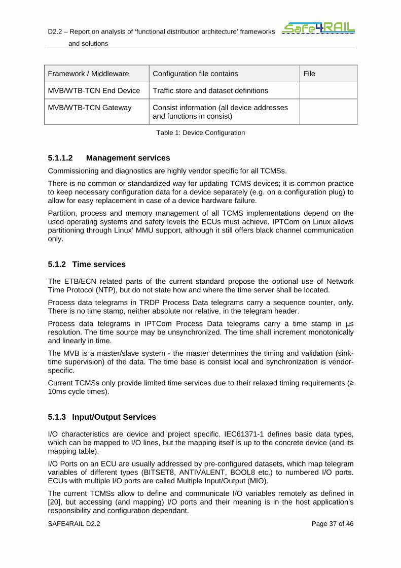
D2.2 – Report on analysis of ‘functional distribution architecture’ frameworks
and solutions
SAFE4RAIL D2.2 Page 37 of 46
Framework / Middleware Configuration file contains File
MVB/WTB-TCN End Device Traffic store and dataset definitions
MVB/WTB-TCN Gateway Consist information (all device addresses and functions in consist)
Table 1: Device Configuration
5.1.1.2 Management services
Commissioning and diagnostics are highly vendor specific for all TCMSs.
There is no common or standardized way for updating TCMS devices; it is common practice to keep necessary configuration data for a device separately (e.g. on a configuration plug) to allow for easy replacement in case of a device hardware failure.
Partition, process and memory management of all TCMS implementations depend on the used operating systems and safety levels the ECUs must achieve. IPTCom on Linux allows partitioning through Linux’ MMU support, although it still offers black channel communication only.
5.1.2 Time services
The ETB/ECN related parts of the current standard propose the optional use of Network Time Protocol (NTP), but do not state how and where the time server shall be located.
Process data telegrams in TRDP Process Data telegrams carry a sequence counter, only. There is no time stamp, neither absolute nor relative, in the telegram header.
Process data telegrams in IPTCom Process Data telegrams carry a time stamp in µs resolution. The time source may be unsynchronized. The time shall increment monotonically and linearly in time.
The MVB is a master/slave system - the master determines the timing and validation (sink-time supervision) of the data. The time base is consist local and synchronization is vendor-specific.
Current TCMSs only provide limited time services due to their relaxed timing requirements (≥ 10ms cycle times).
5.1.3 Input/Output Services
I/O characteristics are device and project specific. IEC61371-1 defines basic data types, which can be mapped to I/O lines, but the mapping itself is up to the concrete device (and its mapping table).
I/O Ports on an ECU are usually addressed by pre-configured datasets, which map telegram variables of different types (BITSET8, ANTIVALENT, BOOL8 etc.) to numbered I/O ports. ECUs with multiple I/O ports are called Multiple Input/Output (MIO).
The current TCMSs allow to define and communicate I/O variables remotely as defined in [20], but accessing (and mapping) I/O ports and their meaning is in the host application’s responsibility and configuration dependant.
D2.2 – Report on analysis of ‘functional distribution architecture’ frameworks
and solutions
SAFE4RAIL D2.2 Page 38 of 46
5.1.4 Real-time support
TRDP's Virtual Operating System (VOS) abstraction layer supports threading services of the underlying operating system and provides those services to the TCMS application. The TCNOpen TRDP implementation only provides a low, single threaded API, although it is prepared for temporal partitioning by use of threads, mutexes and communication queues.
IPTCom provides a higher level interface including a system-wide service (not on VxWorks), which allows several spatial partitioned processes to communicate via one IPTCom instance. This imposes an additional latency due to the use of system queues and additional buffering.
10ms is the minimal interval time for process data a device must be able to handle (according to [IEC61375-2-3]). However, there is no hard real time handling, if the underlying operating system does not support it [21].
TCNOpen TRDP can be extended to support hard real time requirements by using a real time OS (e.g. VxWorks, rcX) and a ‘driving’ application.
5.1.5 Fault isolation
TCNOpen TRDP does not support memory space partitioning by itself because of its low level API. If the underlying operating system supports spatial partitioning the API could provide those services to a TCMS application.
IPTCom provides spatial partitioning by a system wide daemon (on Linux and Windows OSes), but data exchange is handled by a shared memory area, where all attached TCMS applications have read/write access to. One application can access other applications communication data.
For completeness: On MVB, depending on the implementation, the traffic store can be accessed by any application.
Fault isolation is not fully handled by any current TCMS framework but is implementation and OS dependant.
5.1.6 Health monitoring
TRDP provides some standardized statistics and error retrieval, mainly simple counters (e.g. number of protocol, Cyclic Redundancy Check (CRC) and timeout errors). Status and diagnosis lie in the responsibility of the TCMS application and is vendor specific. The same applies to IPTCom and MVB. The extent of logging information can be set by the device’s configuration and/or by the TCMS application. Counters and statistics can be retrieved remotely by special request messages (Annex A of [22] for TRDP, see [23] for IPTCom).
All TCMSs fulfil the high level requirements for health monitoring defined in D2.1 [1]. Chapter 2.1.6 to some extent. The TCMS application is responsible to supply this information.
5.1.7 Security services
Confidentiality: Network traffic is not encrypted [22] Annex B, [24].
Authenticity: Safe Data Transmission (SDT) protected messages (SIL2) are validated by verifying the correct sender and telegram timing, only [22] Annex B.
D2.2 – Report on analysis of ‘functional distribution architecture’ frameworks
and solutions
SAFE4RAIL D2.2 Page 39 of 46
Data Integrity: Without SDT, TRDP protects data only by a 32Bit frame checksum (FCS) over the protocol header. TRDP relies on the Ethernet FCS for transmission errors on non-safe data. IPTCom provides a higher data integrity: Each block of 256 bytes user data is protected by a 32Bit CRC [24].
Provision against security threads is mainly realized by network isolation using hardware gateways/firewalls to deny/allow only specific traffic to the TCMS network ('closed network').
TRDP and IPTCom depend on project/system wide measures for security by network layout, while MVB through the master/slave communication concept is less vulnerable to e.g. intruders.
5.1.8 Requirements for underlying platform
IPTCom demands the most system resources: 4-8MB of memory, 100MIPS for medium sized traffic handling, multithreaded operating system. All three TCMSs can use at least VxWorks, Linux/POSIX and Integrity as underlying operating system.
Framework / Middleware
Threads / Tasks
Memory Performance needs (average)
Cycle / Priority
TCNOpen TRDP [21]
≥ 2 ≥ 500kB ca. 50MIPS ≥10ms/high
IPTCom [23] ≥ 4 ≥ 4MB ca. 100MIPS ≥10ms/high
MVB-TCN
[25]
≥ 2 unknown unknown ≥16ms/high
Table 2: TCMS Needed Resources
5.1.9 Safety Services
All TCMSs support an optional safety layer SDT (Safe Data Transmission). It provides a safe communication path between a source of safety related data and one or several sinks of those data. “The SDT channel” starts and ends at safe applications. The safety devices use the same communication channel as standard/non-safe devices. The SDT-Layer at source side adds protocol information and on that basis the receiver side validates the received telegrams.
Additional measures (‘safe’ CPU, extended memory checks, dual channel computation etc.) need to be taken, apart from using SDT to achieve any SIL level. Any TCMS communication is currently considered as black channel communication.
SIL 2 can be achieved. (See Annex B)
D2.2 – Report on analysis of ‘functional distribution architecture’ frameworks
and solutions
SAFE4RAIL D2.2 Page 40 of 46
5.2 Non-technical characteristics
5.2.1 System Architecture Engineering Method
System design for any of the mentioned TCMSs is vendor specific. Every rail vehicle manufacturer maintains its own tool chains. One common method for consist functional design uses the standard IEC 61131 [26] to program Programmable Logic Controller (PLCs).
5.2.2 Safety and the relevant standards
Current implementations of MVB or IPTCom based TCMSs had, at least in Europe, to follow the according standards (EN 50126, EN 50128, EN 50129, EN 50159) regarding software. Coverage of these standards has been shown in D2.1 SOTA Chapter 2.2.2 [1].
As software needs hardware to run, for railway hardware the EN 50155 needs to be followed (and depending on requirements from railway operators additional regulations may apply).
Although the defined standard for Ethernet-based TCMS supports several measures to be able to reach at least safety level SIL 2, some definitions are vague i.e. may lead to misunderstandings. For example, an IEC compliant train switch (ETBN) must be developed and manufactured in accordance with SIL 2, because any SIL 2 compliant end device in an ECN depends on direction information provided by the ECSP (which in turn relies on inauguration information from the ETBN).
Higher levels of safety integrity were achieved by providing separate train lines in addition to the ETB (e.g. pneumatic brake control, direction indication through separate control line etc.).
To reduce these separate train lines, devices on the ETB, respective the distributed framework, must provide similar safety measures defined in EN 50128 for SIL 4.
5.2.3 Security and the relevant standards
Security in all mentioned TCMSs is currently only available when defined and instantiated as a 'closed network'. Physical access to the TCMS network is often protected by locked switchboards, sometimes only protected by a simple carriage key - some systems may allow access to the network cables from outside the carbine and in case WLAN is used, this also will add to its vulnerability.
[19] is a series of standards that define procedures for implementing secure industrial control systems. It applies to system integrators, security practitioners, and control systems manufacturers responsible for manufacturing, designing, implementing, or managing industrial automation and control systems. As long as "Railway Applications - Communication, signalling and processing systems – IT security requirements for electronic systems for signalling" is under preparation (see D2.1 2.2.3 [1]), [19] is the relevant standard for any TCMS.
Rail vehicle manufacturers and subsystem suppliers must also maintain their IT-infrastructure (tool chain) according to [27], to ensure the correct behaviour of all tools and their output (applications, firmware and configurations).
D2.2 – Report on analysis of ‘functional distribution architecture’ frameworks
and solutions
SAFE4RAIL D2.2 Page 41 of 46
Chapter 6 Summary and conclusion
The main objective of Safe4RAIL project is to develop a framework for the modular integration and execution of mixed-criticality TCMS applications with safety, security and real-time requirements, for what it must support functional distribution, application interoperability, system reconfiguration, deterministic communication and hardware abstraction.
This document provides a detailed analysis of the features offered by generic and domain-specific solutions with similar goals to the ones of the next generation TCMS framework. In particular, RTOS, hypervisor, AUTOSAR, ARINC 653 and existing TCMSs have been compared with the high level requirements defined in D2.1.
In the hypervisor domain PikeOS and XtratuM have been analysed, coming to the conclusion that PikeOS has some technical characteristics regarding its partitioning scheme that have made it the first SIL4 hypervisor certified according to EN 50128 on a multi-core platform, and thus it is a proper technology on which to build the next generation TCMS framework.
In the operating systems field Integrity, VxWorks and LynxOS have been compared, concluding that Integrity could be a potential candidate because of its scheduling and resource allocation strategies and numerous safety certifications such as FAA: DO-178B, Level A and IEC: 61508 SIL 3.
The technical analysis of AUTOSAR has revealed that it fulfils the high level requirements related with partition, process, time, memory and communication management, discovery, time, input/output and security services, as well as real-time support, fault isolation and health monitoring. However, the static configuration scheme of AUTOSAR makes difficult to cover the requirement to handle online system reconfiguration at train inauguration. Regarding EN 50128 safety and IEC 62443-3-3 security standards, there are no blocking requirements that would prevent AUTOSAR to be used in accordance with them, although it does not cover all of the requirements. Additionally, AUTOSAR defines a system architecture engineering methodology, covering all the major steps of the development of a system and defining a common technical approach in the system development.
The technical analysis of ARINC 653 shows that it fulfils completely the high level requirements of process management, time services, fault isolation and health monitoring, whereas the ones related with partition and memory management as well as real-time support are covered only partially because they can be carried out statically but not dynamically. In general, ARINC 653 does not allow runtime (re)configuration of the system and does not provide input/output and security services. Regarding EN 50128 and IEC 62443-3-3, there are no blocking requirements that would prevent ARINC 653 to be used in accordance with them, although it does not cover all of the requirements of the first one and none of the second. ARINC 653 does not define a standard development methodology but there are research works that make relevant contributions to this topic.
The technical analysis of existing TCMSs standards and technologies such as IPTCom, TRDP and MVB has revealed that they fulfil to some extent the high level requirements of only health monitoring, security services, spatial partition in the case of IPTCom and time services in the case of MVB. On the other hand, it seems that there are no blocking requirements that would prevent these technologies to be used in accordance with the EN

D2.2 – Report on analysis of ‘functional distribution architecture’ frameworks
and solutions
SAFE4RAIL D2.2 Page 42 of 46
50128 and IEC 62443-3-3. Finally, it should be mentioned that there is no standard engineering methodology defined in the context of the exiting TCMSs.
To summarize, the main conclusion that can be extracted is that none of the analyzed technologies cover all the defined high level requirements, so they cannot be used directly to solve the problem approached in Safe4RAIL project. Nevertheless, ARINC 653 and specially AUTOSAR offer some very interesting features and solutions that have to be taken into account during the definition, design and development of the next generation TCMS framework.
D2.2 – Report on analysis of ‘functional distribution architecture’ frameworks
and solutions
SAFE4RAIL D2.2 Page 43 of 46
Chapter 7 List of Abbreviations
ACR Avionics Computer Resource
AMP Asymmetric Multiprocessing
APEX APplication/EXecutive
API Application Program Interface
ARINC Avionics Application Standard Software Interface
ARP Address Resolution Protocol
AUTOSAR Automotive Open System Architecture
BIT Build in Tests
BSP Board Support Package
BSW Basic Software
CAN Controller Area Network
COTS Commercial Off The Shelf
CPU Central Processing Unit
CRC Cyclic Redundancy Check
CSW Core Software
ECN Ethernet Consist Network
ECSP ETB Control Service Provider
ECU Electronic Control Unit
ETB Ethernet Train Backbone
ETBN Ethernet Train Backbone Node
FCS Frame CheckSum
FreeBSD Unix implementation (Berkley Software Distribution)

D2.2 – Report on analysis of ‘functional distribution architecture’ frameworks
and solutions
SAFE4RAIL D2.2 Page 44 of 46
HM Health Monitoring
I/O Input/Output
IDE Integrated Development Environment
IPTCom IP-Train Communication (Implementation of the IP-Train Wire protocol, prpriatary )
IPTDir IP-Train Directory services
MCU Memory Control Unit
MFESA Method Framework for Engineering System Architectures
MIO Multiple Input/Output
MMU Memory Management Unit
MPU Memory Protection Unit
MVB Multifunction Vehicle Bus
NTP Network Time Protocol
OS Operating System
PLCs Programmable Logic Controller
POSIX Portable Operating System Interface for UNIX
RAMS Reliability, Availability, Maintainability and Safety
ROM Read Only Memory
RT Real Time
RTOS Real Time Operating System
RTP Real Time Process
Safe4RAIL Safe architecture for Robust distributed Application Integration in roLling stock
SDT Safe Data Transmission
SIL Safety Integrity Level
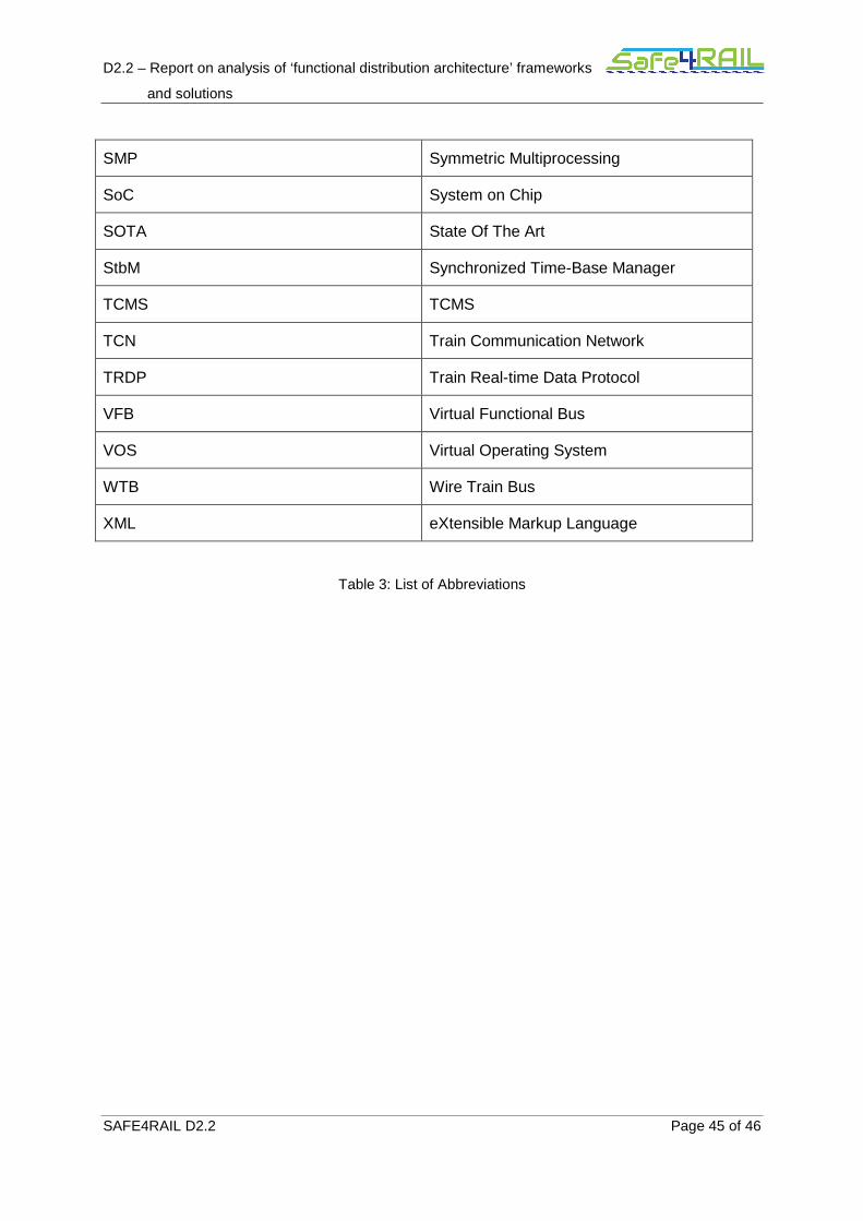
D2.2 – Report on analysis of ‘functional distribution architecture’ frameworks
and solutions
SAFE4RAIL D2.2 Page 45 of 46
SMP Symmetric Multiprocessing
SoC System on Chip
SOTA State Of The Art
StbM Synchronized Time-Base Manager
TCMS TCMS
TCN Train Communication Network
TRDP Train Real-time Data Protocol
VFB Virtual Functional Bus
VOS Virtual Operating System
WTB Wire Train Bus
XML eXtensible Markup Language
Table 3: List of Abbreviations
D2.2 – Report on analysis of ‘functional distribution architecture’ frameworks
and solutions
SAFE4RAIL D2.2 Page 46 of 46
Chapter 8 Bibliography
[1] „D2.1 Report on state-of-the-art of 'functional distribution architecture' frameworks and solutions,“ Safe4RAIL Project, 2016.
[2] S. Whitepaper, „PikeOS Safe Real-Time Scheduling - Adaptive Time-Partitioning Scheduler for EN 50128 certified Multicore Platform,“ 2016.
[3] „Sysgo.com,“ Embedding Innovation, [Online]. Available: https://www.sysgo.com/products/pikeos-hypervisor/safety-architecture/. [Access on 16 02 2017].
[4] E. CENELEC, „50128-Railway applications-Communication, signalling and processing systems-Software for railway control and protection systems,“ Book EN, 2012.
[5] Airlines Electronic Engineering Committee et al., „Avionics application software standard interface part 0 overview of ARINC 653. ARINC Document ARINC Specification 653P1-2,“ Aeronautical Radio, Inc., Annapolis, Maryland, 2015.
[6] „Sysgo PikeOS RTOS Technology,“ [Online]. Available: https://www.sysgo.com/products/pikeos-hypervisor/rtos-technology/. [Access on 16 02 2017].
[7] S. a. M. J. a. B. S. a. W. T. a. K.-B. F. a. H. P. a. K. G. a. N. K. a. L. K. Fürst, AUTOSAR--A Worldwide Standard is on the Road, Baden-Baden: 14th International VDI Congress Electronic Systems for Vehicles, 2009.
[8] „Sysgo Eclipse based development,“ [Online]. Available: https://www.sysgo.com/products/pikeos-hypervisor/eclipse-based-codeo/. [Access on 16 02 2017].
[9] I. R. a. A. C. M. Masmano, „XtratuM: a Hypervisor for Safety Critical Embedded Systems,“ Instituto de Informatica Industrial, Universidad Politecnica de Valencia (Spain).
[10] I. R. M. M. P. A. a. J. M. A. Crespo, „XTRATUM: AN OPEN SOURCE HYPERVISOR FOR TSP EMBEDDED SYSTEMS IN,“ Instituto de Inform´atica Industrial, Universidad Polit´ecnica de Valencia, Spain, CNES, France.
[11] „https://www.windriver.com“.
[12] D. W. R. Obermaisser, „Architectures for Mixed-Criticality Systems based on Networked Multi-Core Chips,“ 2014.
D2.2 – Report on analysis of ‘functional distribution architecture’ frameworks
and solutions
SAFE4RAIL D2.2 Page 47 of 46
[13] P. P. a. L. Kinnan., „Safety-critical software development for integrated modular avionics.,“ Embedded System Engineering, 2003.
[14] „http://www.lynx.com/“.
[15] „http://www.ghs.com/products/rtos/integrity_virtualization.html“.
[16] „Integrity RTOS,“ Green Hills, [Online]. Available: http://www.ghs.com/products/rtos/integrity.html. [Access on 17 02 2017].
[17] AUTOSAR, „Specification of ECU Configuration,“ 2016.
[18] AUTOSAR, „Specification of Operating System,“ 2016.
[19] AUTOSAR, „Specification of Memory Mapping,“ 2016.
[20] AUTOSAR, „Specification of RTE,“ 2016.
[21] AUTOSAR, „Specification of Timing Extentions,“ 2016.
[22] AUTOSAR, „Autosar Methodology,“ 2016.
[23] Y. Y. Z. S. D. &. L. Y. Zhao, „Event-based Formalization of Safety-critical Operating System Standards: An Experience Report on ARINC 653 using Event-B,“ in Software Reliability Engineering (ISSRE), 2015 IEEE 26th International Symposium on, IEEE, 2015, pp. 281--292.
[24] D. G. a. C. P. a. F. D. a. H. C. B. a. L. I. D. T. a. M. T. Firesmith, „The method framework for engineering system architectures,“ CRC Press, 2008.
[25] Industrial communication networks. Network and system security. System security requirements and security levels, BS IEC 62443-3-3:2013-10-31.
[26] Electronic railway equipment - Train communication network - Part 1: TCN - Train Communication Network General Architecture", EN 61375-1:2012.
[27] TRDP User’s Manual, TCN-TRDP2-D-BOM-011-27.
[28] Electronic railway equipment – Train communication network (TCN) - Part 2-3: TCN communication profile, EN 61375-2-3:2015 + AC:2016-01 + AC:2016-11.
[29] IPTCom User and Integration Manual, 3EGM019001-0224 AB (Bombardier).
[30] IPT Wire Protocols, 3EST000211-9664, Rev. C (Bombardier).
[31] Electronic Railway Equipment - Train Communication Network - Part 3-1: MVB - Multipurpose Vehicle Bus, EN 61375-3-1:2012.
D2.2 – Report on analysis of ‘functional distribution architecture’ frameworks
and solutions
SAFE4RAIL D2.2 Page 48 of 46
[32] Programmable Controllers - Part 3: Programming Languages, IEC 61131-3:2013.
[33] Information technology - Security techniques - Information security management systems - Requirements, ISO/IEC 27001:2013-10 .
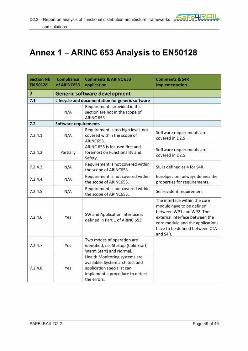
D2.2 – Report on analysis of ‘functional distribution architecture’ frameworks
and solutions
SAFE4RAIL D2.2 Page 49 of 46
Annex 1 – ARINC 653 Analysis to EN50128
Section Nb
EN 50128
Compliance
of ARINC653
Comments & ARINC 653
application
Comments & S4R
Implementation
7 Generic software development
7.1 Lifecycle and documentation for generic software
N/A
Requirements provided in this
section are not in the scope of
ARINC 653
7.2 Software requirements
7.2.4.1 N/A
Requirement is too high level, not
covered within the scope of
ARINC653.
Software requirements are
covered in D2.5
7.2.4.2 Partially
ARINC 653 is focused first and
foremost on Functionality and
Safety.
Software requirements are
covered in D2.5
7.2.4.3 N/A Requirement is not covered within
the scope of ARINC653. SIL is defined as 4 for S4R.
7.2.4.4 N/A Requirement is not covered within
the scope of ARINC653.
EuroSpec on railways defines the
properties for requirements.
7.2.4.5 N/A Requirement is not covered within
the scope of ARINC653. Self-evident requirement
7.2.4.6 Yes SW and Application interface is
defined in Part 1 of ARINC 653
The interface within the core
module have to be defined
between WP1 and WP2. The
external interface between the
core module and the applications
have to be defined between CTA
and S4R.
7.2.4.7 Yes
Two modes of operation are
identified, i.e. Startup (Cold Start,
Warm Start) and Normal.
7.2.4.8 Yes
Health Monitoring systems are
available. System architect and
application specialist can
implement a procedure to detect
the errors.
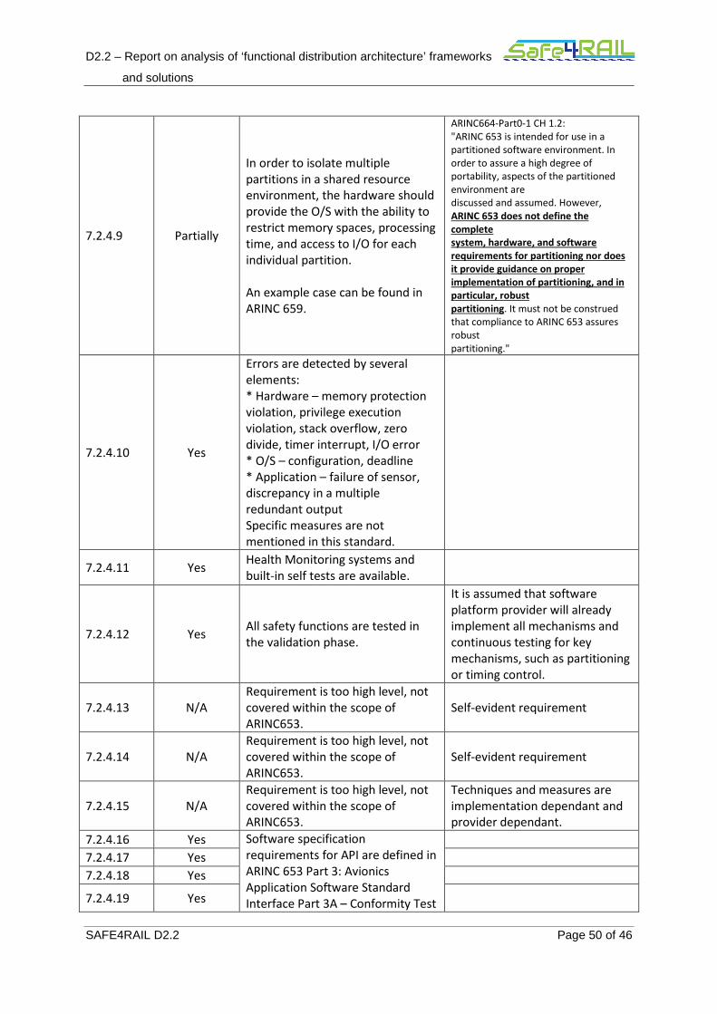
D2.2 – Report on analysis of ‘functional distribution architecture’ frameworks
and solutions
SAFE4RAIL D2.2 Page 50 of 46
7.2.4.9 Partially
In order to isolate multiple
partitions in a shared resource
environment, the hardware should
provide the O/S with the ability to
restrict memory spaces, processing
time, and access to I/O for each
individual partition.
An example case can be found in
ARINC 659.
ARINC664-Part0-1 CH 1.2:
"ARINC 653 is intended for use in a
partitioned software environment. In
order to assure a high degree of
portability, aspects of the partitioned
environment are
discussed and assumed. However,
ARINC 653 does not define the
complete
system, hardware, and software
requirements for partitioning nor does
it provide guidance on proper
implementation of partitioning, and in
particular, robust
partitioning. It must not be construed
that compliance to ARINC 653 assures
robust
partitioning."
7.2.4.10 Yes
Errors are detected by several
elements:
* Hardware – memory protection
violation, privilege execution
violation, stack overflow, zero
divide, timer interrupt, I/O error
* O/S – configuration, deadline
* Application – failure of sensor,
discrepancy in a multiple
redundant output
Specific measures are not
mentioned in this standard.
7.2.4.11 Yes Health Monitoring systems and
built-in self tests are available.
7.2.4.12 Yes All safety functions are tested in
the validation phase.
It is assumed that software
platform provider will already
implement all mechanisms and
continuous testing for key
mechanisms, such as partitioning
or timing control.
7.2.4.13 N/A
Requirement is too high level, not
covered within the scope of
ARINC653.
Self-evident requirement
7.2.4.14 N/A
Requirement is too high level, not
covered within the scope of
ARINC653.
Self-evident requirement
7.2.4.15 N/A
Requirement is too high level, not
covered within the scope of
ARINC653.
Techniques and measures are
implementation dependant and
provider dependant.
7.2.4.16 Yes Software specification
requirements for API are defined in
ARINC 653 Part 3: Avionics
Application Software Standard
Interface Part 3A – Conformity Test
7.2.4.17 Yes
7.2.4.18 Yes
7.2.4.19 Yes
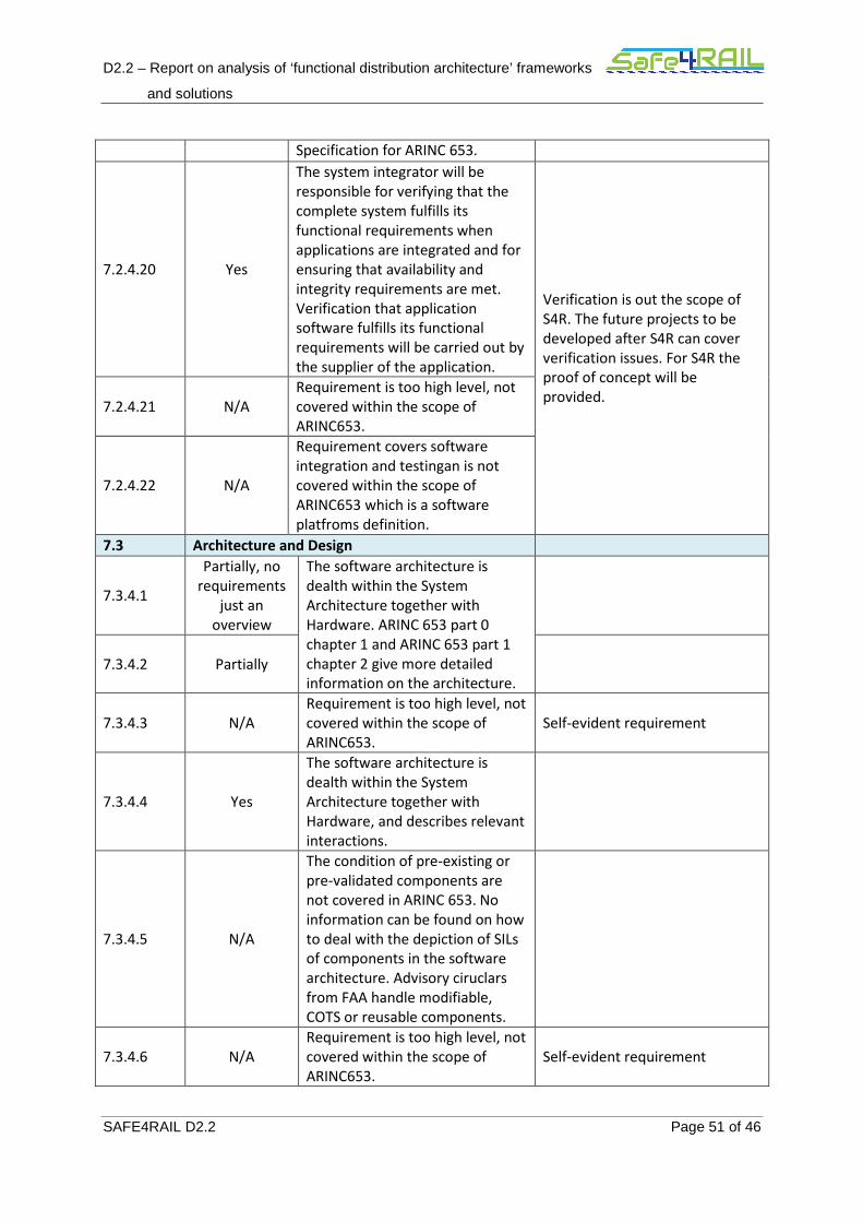
D2.2 – Report on analysis of ‘functional distribution architecture’ frameworks
and solutions
SAFE4RAIL D2.2 Page 51 of 46
Specification for ARINC 653.
7.2.4.20 Yes
The system integrator will be
responsible for verifying that the
complete system fulfills its
functional requirements when
applications are integrated and for
ensuring that availability and
integrity requirements are met.
Verification that application
software fulfills its functional
requirements will be carried out by
the supplier of the application.
Verification is out the scope of
S4R. The future projects to be
developed after S4R can cover
verification issues. For S4R the
proof of concept will be
provided. 7.2.4.21 N/A
Requirement is too high level, not
covered within the scope of
ARINC653.
7.2.4.22 N/A
Requirement covers software
integration and testingan is not
covered within the scope of
ARINC653 which is a software
platfroms definition.
7.3 Architecture and Design
7.3.4.1
Partially, no
requirements
just an
overview
The software architecture is
dealth within the System
Architecture together with
Hardware. ARINC 653 part 0
chapter 1 and ARINC 653 part 1
chapter 2 give more detailed
information on the architecture.
7.3.4.2 Partially
7.3.4.3 N/A
Requirement is too high level, not
covered within the scope of
ARINC653.
Self-evident requirement
7.3.4.4 Yes
The software architecture is
dealth within the System
Architecture together with
Hardware, and describes relevant
interactions.
7.3.4.5 N/A
The condition of pre-existing or
pre-validated components are
not covered in ARINC 653. No
information can be found on how
to deal with the depiction of SILs
of components in the software
architecture. Advisory ciruclars
from FAA handle modifiable,
COTS or reusable components.
7.3.4.6 N/A
Requirement is too high level, not
covered within the scope of
ARINC653.
Self-evident requirement

D2.2 – Report on analysis of ‘functional distribution architecture’ frameworks
and solutions
SAFE4RAIL D2.2 Page 52 of 46
7.3.4.7 N/A
The condition of pre-existing
components are not covered in
ARINC 653.
7.3.4.8 N/A
The condition of pre-existing
components are not covered in
ARINC 653.
Self-evident requirement
7.3.4.9 N/A
The SILs of components are not
covered in the scope of ARINC
653
Self-evident requirement
7.3.4.10 N/A
Requirement is too high level, not
covered within the scope of
ARINC653.
Self-evident requirement
7.3.4.11 Yes
Processes may be designed for
periodic or aperiodic execution,
the occurrence of a fault may
require processes to be
reinitialized or terminated, and a
method to prevent a running
process from being preempted is
required in order to safely access
resources that demand mutually-
exclusive access.
7.3.4.12 N/A
Requirement is too high level, not
covered within the scope of
ARINC653.
Self-evident requirement
7.3.4.13 Yes
The aim of ARINC 653 is to define
this interface between the
Applications and the Core
Software. Parts 1 and 2 of ARINC
653 provide a very detailed set of
considerations regarding this
interface.
7.3.4.14 Yes
Some of the techniques and
measures are mentioned in the
scope of ARINC 653.
7.3.4.15
Partly
(implementati
on-specific)
Instead of architecture level
definition, ARINC 653 defines the
interface between Core SW and
Applications. According to ARINC
653:
It is intended for this interface to
be as generic as possible, since an
interface with too much
complexity or too many system-
specific features is normally not
accepted over a variety of
systems. The software
specifications of the APEX
interface are High-Order
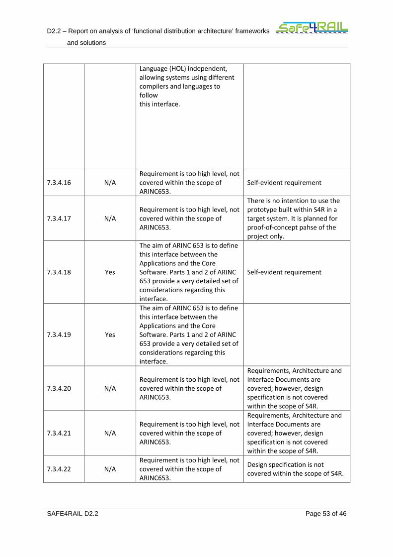
D2.2 – Report on analysis of ‘functional distribution architecture’ frameworks
and solutions
SAFE4RAIL D2.2 Page 53 of 46
Language (HOL) independent,
allowing systems using different
compilers and languages to
follow
this interface.
7.3.4.16 N/A
Requirement is too high level, not
covered within the scope of
ARINC653.
Self-evident requirement
7.3.4.17 N/A
Requirement is too high level, not
covered within the scope of
ARINC653.
There is no intention to use the
prototype built within S4R in a
target system. It is planned for
proof-of-concept pahse of the
project only.
7.3.4.18 Yes
The aim of ARINC 653 is to define
this interface between the
Applications and the Core
Software. Parts 1 and 2 of ARINC
653 provide a very detailed set of
considerations regarding this
interface.
Self-evident requirement
7.3.4.19 Yes
The aim of ARINC 653 is to define
this interface between the
Applications and the Core
Software. Parts 1 and 2 of ARINC
653 provide a very detailed set of
considerations regarding this
interface.
7.3.4.20 N/A
Requirement is too high level, not
covered within the scope of
ARINC653.
Requirements, Architecture and
Interface Documents are
covered; however, design
specification is not covered
within the scope of S4R.
7.3.4.21 N/A
Requirement is too high level, not
covered within the scope of
ARINC653.
Requirements, Architecture and
Interface Documents are
covered; however, design
specification is not covered
within the scope of S4R.
7.3.4.22 N/A
Requirement is too high level, not
covered within the scope of
ARINC653.
Design specification is not
covered within the scope of S4R.
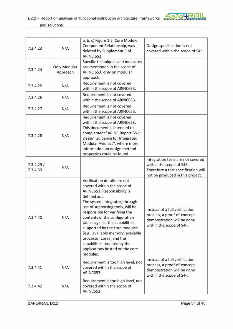
D2.2 – Report on analysis of ‘functional distribution architecture’ frameworks
and solutions
SAFE4RAIL D2.2 Page 54 of 46
7.3.4.23 N/A
a, b, c) Figure 1.2, Core Module
Component Relationship, was
deleted by Supplement 3 of
ARINC 653.
Design specification is not
covered within the scope of S4R.
7.3.4.24 Only Modular
Approach
Specific techniques and measures
are mentioned in the scope of
ARINC 653, only on modular
approach.
7.3.4.25 N/A Requirement is not covered
within the scope of ARINC653.
7.3.4.26 N/A Requirement is not covered
within the scope of ARINC653.
7.3.4.27 N/A Requirement is not covered
within the scope of ARINC653.
7.3.4.28 N/A
Requirement is not covered
within the scope of ARINC653.
This document is intended to
complement "ARINC Report 651:
Design Guidance for Integrated
Modular Avionics", where more
information on design method
properties could be found.
7.3.4.29 /
7.3.4.39 N/A
Integration tests are not covered
within the scope of S4R.
Therefore a test specification will
not be produced in this project.
7.3.4.40 N/A
Verification details are not
covered within the scope of
ARINC653. Responsibility is
defined as :
The system integrator, through
use of supporting tools, will be
responsible for verifying the
contents of the configuration
tables against the capabilities
supported by the core modules
(e.g., available memory, available
processor cores) and the
capabilities required by the
applications hosted on the core
modules.
Instead of a full verification
process, a proof-of-concept
demonstration will be done
within the scope of S4R.
7.3.4.41 N/A
Requirement is too high level, not
covered within the scope of
ARINC653.
Instead of a full verification
process, a proof-of-concept
demonstration will be done
within the scope of S4R.
7.3.4.42 N/A
Requirement is too high level, not
covered within the scope of
ARINC653.
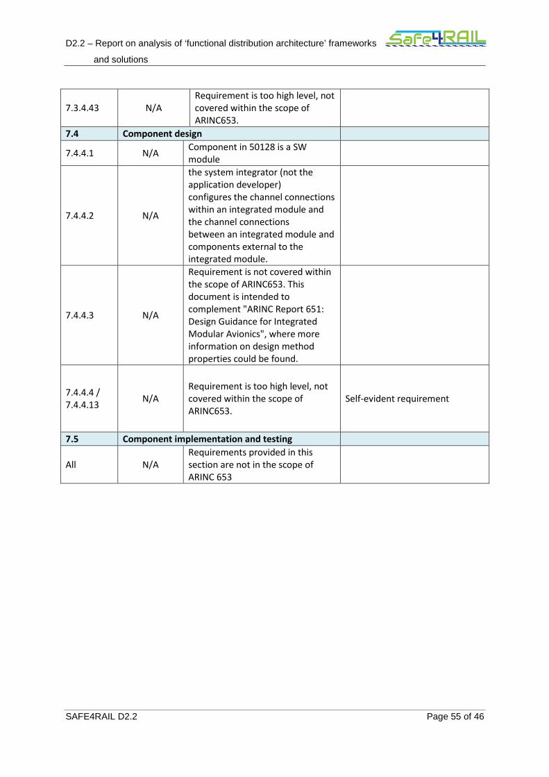
D2.2 – Report on analysis of ‘functional distribution architecture’ frameworks
and solutions
SAFE4RAIL D2.2 Page 55 of 46
7.3.4.43 N/A
Requirement is too high level, not
covered within the scope of
ARINC653.
7.4 Component design
7.4.4.1 N/A Component in 50128 is a SW
module
7.4.4.2 N/A
the system integrator (not the
application developer)
configures the channel connections
within an integrated module and
the channel connections
between an integrated module and
components external to the
integrated module.
7.4.4.3 N/A
Requirement is not covered within
the scope of ARINC653. This
document is intended to
complement "ARINC Report 651:
Design Guidance for Integrated
Modular Avionics", where more
information on design method
properties could be found.
7.4.4.4 /
7.4.4.13 N/A
Requirement is too high level, not
covered within the scope of
ARINC653.
Self-evident requirement
7.5 Component implementation and testing
All N/A
Requirements provided in this
section are not in the scope of
ARINC 653
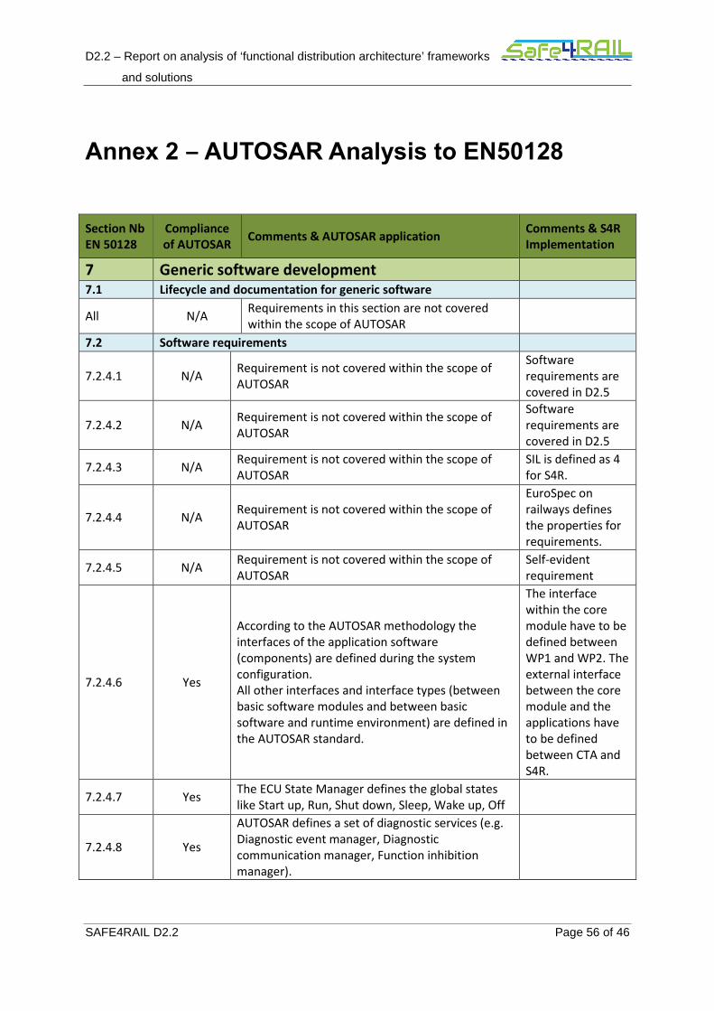
D2.2 – Report on analysis of ‘functional distribution architecture’ frameworks
and solutions
SAFE4RAIL D2.2 Page 56 of 46
Annex 2 – AUTOSAR Analysis to EN50128
Section Nb
EN 50128
Compliance
of AUTOSAR Comments & AUTOSAR application
Comments & S4R
Implementation
7 Generic software development
7.1 Lifecycle and documentation for generic software
All N/A Requirements in this section are not covered
within the scope of AUTOSAR
7.2 Software requirements
7.2.4.1 N/A Requirement is not covered within the scope of
AUTOSAR
Software
requirements are
covered in D2.5
7.2.4.2 N/A Requirement is not covered within the scope of
AUTOSAR
Software
requirements are
covered in D2.5
7.2.4.3 N/A Requirement is not covered within the scope of
AUTOSAR
SIL is defined as 4
for S4R.
7.2.4.4 N/A Requirement is not covered within the scope of
AUTOSAR
EuroSpec on
railways defines
the properties for
requirements.
7.2.4.5 N/A Requirement is not covered within the scope of
AUTOSAR
Self-evident
requirement
7.2.4.6 Yes
According to the AUTOSAR methodology the
interfaces of the application software
(components) are defined during the system
configuration.
All other interfaces and interface types (between
basic software modules and between basic
software and runtime environment) are defined in
the AUTOSAR standard.
The interface
within the core
module have to be
defined between
WP1 and WP2. The
external interface
between the core
module and the
applications have
to be defined
between CTA and
S4R.
7.2.4.7 Yes The ECU State Manager defines the global states
like Start up, Run, Shut down, Sleep, Wake up, Off
7.2.4.8 Yes
AUTOSAR defines a set of diagnostic services (e.g.
Diagnostic event manager, Diagnostic
communication manager, Function inhibition
manager).
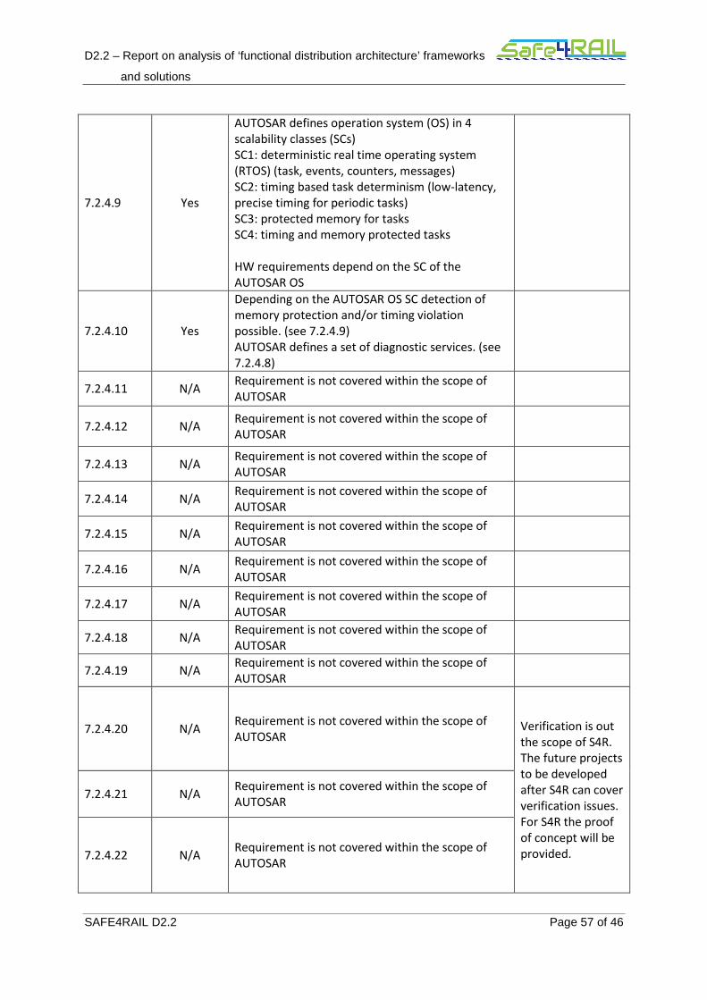
D2.2 – Report on analysis of ‘functional distribution architecture’ frameworks
and solutions
SAFE4RAIL D2.2 Page 57 of 46
7.2.4.9 Yes
AUTOSAR defines operation system (OS) in 4
scalability classes (SCs)
SC1: deterministic real time operating system
(RTOS) (task, events, counters, messages)
SC2: timing based task determinism (low-latency,
precise timing for periodic tasks)
SC3: protected memory for tasks
SC4: timing and memory protected tasks
HW requirements depend on the SC of the
AUTOSAR OS
7.2.4.10 Yes
Depending on the AUTOSAR OS SC detection of
memory protection and/or timing violation
possible. (see 7.2.4.9)
AUTOSAR defines a set of diagnostic services. (see
7.2.4.8)
7.2.4.11 N/A Requirement is not covered within the scope of
AUTOSAR
7.2.4.12 N/A Requirement is not covered within the scope of
AUTOSAR
7.2.4.13 N/A Requirement is not covered within the scope of
AUTOSAR
7.2.4.14 N/A Requirement is not covered within the scope of
AUTOSAR
7.2.4.15 N/A Requirement is not covered within the scope of
AUTOSAR
7.2.4.16 N/A Requirement is not covered within the scope of
AUTOSAR
7.2.4.17 N/A Requirement is not covered within the scope of
AUTOSAR
7.2.4.18 N/A Requirement is not covered within the scope of
AUTOSAR
7.2.4.19 N/A Requirement is not covered within the scope of
AUTOSAR
7.2.4.20 N/A Requirement is not covered within the scope of
AUTOSAR Verification is out
the scope of S4R.
The future projects
to be developed
after S4R can cover
verification issues.
For S4R the proof
of concept will be
provided.
7.2.4.21 N/A Requirement is not covered within the scope of
AUTOSAR
7.2.4.22 N/A Requirement is not covered within the scope of
AUTOSAR

D2.2 – Report on analysis of ‘functional distribution architecture’ frameworks
and solutions
SAFE4RAIL D2.2 Page 58 of 46
7.3 Architecture and Design
7.3.4.1 Partially
AUTOSAR requires a common technical approach
for some steps of system development.
This approach is called the AUTOSAR
methodology.
The AUTOSAR methodology defines roles and
responsibilities.
7.3.4.2 Yes AUTOSAR defines standardized architecture
definition.
7.3.4.3 Partially
Depending on the requested SIL level of the
application the decision for different AUTOSAR
OS SCs could be taken by the architect.
This results in different services provided by the
OS.
Self-evident
requirement
7.3.4.4 Yes
Application software in AUTOSAR is decoupled
from the ECU hardware by the mean of the
Runtime Environment (RTE) and the Virtual
Functional Bus.
The RTE must be individually generated for each
ECU configuration.
7.3.4.5 N/A Requirement is not covered within the scope of
AUTOSAR
7.3.4.6 N/A Requirement is not covered within the scope of
AUTOSAR
Self-evident
requirement
7.3.4.7 N/A Requirement is not covered within the scope of
AUTOSAR
7.3.4.8 N/A Requirement is not covered within the scope of
AUTOSAR
Self-evident
requirement
7.3.4.9 N/A Requirement is not covered within the scope of
AUTOSAR
Self-evident
requirement
7.3.4.10 Partially
AUTOSAR defines standardized architecture
definition.
Traceability of requirements toward software
architecture definition oi not covered within the
scope of AUTOSAR.
Self-evident
requirement
7.3.4.11 Yes
AUTOSAR provides the so-called Function
Inhibition Manager (FiM), which is responsible is
responsible for providing a control mechanism
for software components and the functionality
therein.
The FiM is closely related to the Diagnostic Event
Manager of AUTOSAR, since diagnostic events
and their status information are used as inhibit
conditions for functionalities in SW components,
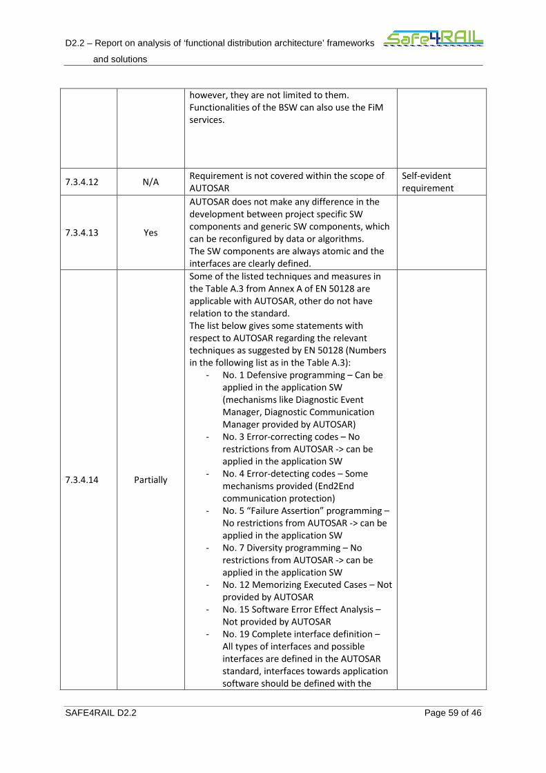
D2.2 – Report on analysis of ‘functional distribution architecture’ frameworks
and solutions
SAFE4RAIL D2.2 Page 59 of 46
however, they are not limited to them.
Functionalities of the BSW can also use the FiM
services.
7.3.4.12 N/A Requirement is not covered within the scope of
AUTOSAR
Self-evident
requirement
7.3.4.13 Yes
AUTOSAR does not make any difference in the
development between project specific SW
components and generic SW components, which
can be reconfigured by data or algorithms.
The SW components are always atomic and the
interfaces are clearly defined.
7.3.4.14 Partially
Some of the listed techniques and measures in
the Table A.3 from Annex A of EN 50128 are
applicable with AUTOSAR, other do not have
relation to the standard.
The list below gives some statements with
respect to AUTOSAR regarding the relevant
techniques as suggested by EN 50128 (Numbers
in the following list as in the Table A.3):
- No. 1 Defensive programming – Can be
applied in the application SW
(mechanisms like Diagnostic Event
Manager, Diagnostic Communication
Manager provided by AUTOSAR)
- No. 3 Error-correcting codes – No
restrictions from AUTOSAR -> can be
applied in the application SW
- No. 4 Error-detecting codes – Some
mechanisms provided (End2End
communication protection)
- No. 5 “Failure Assertion” programming –
No restrictions from AUTOSAR -> can be
applied in the application SW
- No. 7 Diversity programming – No
restrictions from AUTOSAR -> can be
applied in the application SW
- No. 12 Memorizing Executed Cases – Not
provided by AUTOSAR
- No. 15 Software Error Effect Analysis –
Not provided by AUTOSAR
- No. 19 Complete interface definition –
All types of interfaces and possible
interfaces are defined in the AUTOSAR
standard, interfaces towards application
software should be defined with the
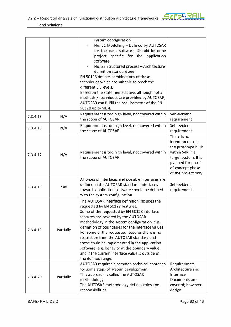
D2.2 – Report on analysis of ‘functional distribution architecture’ frameworks
and solutions
SAFE4RAIL D2.2 Page 60 of 46
system configuration
- No. 21 Modelling – Defined by AUTOSAR
for the basic software. Should be done
project specific for the application
software
- No. 22 Structured process – Architecture
definition standardized
EN 50128 defines combinations of these
techniques which are suitable to reach the
different SIL levels.
Based on the statements above, although not all
methods / techniques are provided by AUTOSAR,
AUTOSAR can fulfill the requirements of the EN
50128 up to SIL 4.
7.3.4.15 N/A Requirement is too high level, not covered within
the scope of AUTOSAR
Self-evident
requirement
7.3.4.16 N/A Requirement is too high level, not covered within
the scope of AUTOSAR
Self-evident
requirement
7.3.4.17 N/A Requirement is too high level, not covered within
the scope of AUTOSAR
There is no
intention to use
the prototype built
within S4R in a
target system. It is
planned for proof-
of-concept phase
of the project only.
7.3.4.18 Yes
All types of interfaces and possible interfaces are
defined in the AUTOSAR standard, interfaces
towards application software should be defined
with the system configuration.
Self-evident
requirement
7.3.4.19 Partially
The AUTOSAR interface definition includes the
requested by EN 50128 features.
Some of the requested by EN 50128 interface
features are covered by the AUTOSAR
methodology in the system configuration, e.g.
definition of boundaries for the interface values.
For some of the requested features there is no
restriction from the AUTOSAR standard and
these could be implemented in the application
software, e.g. behavior at the boundary value
and if the current interface value is outside of
the defined range.
7.3.4.20 Partially
AUTOSAR requires a common technical approach
for some steps of system development.
This approach is called the AUTOSAR
methodology.
The AUTOSAR methodology defines roles and
responsibilities.
Requirements,
Architecture and
Interface
Documents are
covered; however,
design
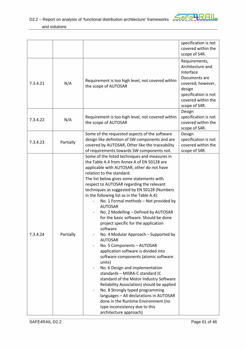
D2.2 – Report on analysis of ‘functional distribution architecture’ frameworks
and solutions
SAFE4RAIL D2.2 Page 61 of 46
specification is not
covered within the
scope of S4R.
7.3.4.21 N/A Requirement is too high level, not covered within
the scope of AUTOSAR
Requirements,
Architecture and
Interface
Documents are
covered; however,
design
specification is not
covered within the
scope of S4R.
7.3.4.22 N/A Requirement is too high level, not covered within
the scope of AUTOSAR
Design
specification is not
covered within the
scope of S4R.
7.3.4.23 Partially
Some of the requested aspects of the software
design like definition of SW components and are
covered by AUTOSAR, Other like the traceability
of requirements towards SW components not.
Design
specification is not
covered within the
scope of S4R.
7.3.4.24 Partially
Some of the listed techniques and measures in
the Table A.4 from Annex A of EN 50128 are
applicable with AUTOSAR, other do not have
relation to the standard.
The list below gives some statements with
respect to AUTOSAR regarding the relevant
techniques as suggested by EN 50128 (Numbers
in the following list as in the Table A.4):
- No. 1 Formal methods – Not provided by
AUTOSAR
- No. 2 Modelling – Defined by AUTOSAR
for the basic software. Should be done
project specific for the application
software
- No. 4 Modular Approach – Supported by
AUTOSAR
- No. 5 Components – AUTOSAR
application software is divided into
software components (atomic software
units)
- No. 6 Design and implementation
standards – MISRA-C standard (C
standard of the Motor Industry Software
Reliability Association) should be applied
- No. 8 Strongly typed programming
languages – All declarations in AUTOSAR
done in the Runtime Environment (no
type inconsistency due to this
architecture approach)
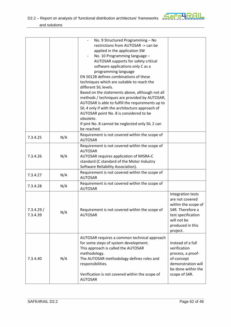
D2.2 – Report on analysis of ‘functional distribution architecture’ frameworks
and solutions
SAFE4RAIL D2.2 Page 62 of 46
- No. 9 Structured Programming – No
restrictions from AUTOSAR -> can be
applied in the application SW
- No. 10 Programming language –
AUTOSAR supports for safety critical
software applications only C as a
programming language
EN 50128 defines combinations of these
techniques which are suitable to reach the
different SIL levels.
Based on the statements above, although not all
methods / techniques are provided by AUTOSAR,
AUTOSAR is able to fulfill the requirements up to
SIL 4 only if with the architecture approach of
AUTOSAR point No. 8 is considered to be
obsolete.
If pint No. 8 cannot be neglected only SIL 2 can
be reached.
7.3.4.25 N/A Requirement is not covered within the scope of
AUTOSAR
7.3.4.26 N/A
Requirement is not covered within the scope of
AUTOSAR
AUTOSAR requires application of MISRA-C
standard (C standard of the Motor Industry
Software Reliability Association).
7.3.4.27 N/A Requirement is not covered within the scope of
AUTOSAR
7.3.4.28 N/A Requirement is not covered within the scope of
AUTOSAR
7.3.4.29 /
7.3.4.39 N/A
Requirement is not covered within the scope of
AUTOSAR
Integration tests
are not covered
within the scope of
S4R. Therefore a
test specification
will not be
produced in this
project.
7.3.4.40 N/A
AUTOSAR requires a common technical approach
for some steps of system development.
This approach is called the AUTOSAR
methodology.
The AUTOSAR methodology defines roles and
responsibilities.
Verification is not covered within the scope of
AUTOSAR
Instead of a full
verification
process, a proof-
of-concept
demonstration will
be done within the
scope of S4R.
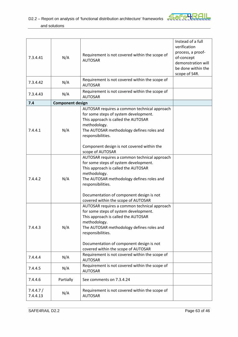
D2.2 – Report on analysis of ‘functional distribution architecture’ frameworks
and solutions
SAFE4RAIL D2.2 Page 63 of 46
7.3.4.41 N/A Requirement is not covered within the scope of
AUTOSAR
Instead of a full
verification
process, a proof-
of-concept
demonstration will
be done within the
scope of S4R.
7.3.4.42 N/A Requirement is not covered within the scope of
AUTOSAR
7.3.4.43 N/A Requirement is not covered within the scope of
AUTOSAR
7.4 Component design
7.4.4.1 N/A
AUTOSAR requires a common technical approach
for some steps of system development.
This approach is called the AUTOSAR
methodology.
The AUTOSAR methodology defines roles and
responsibilities.
Component design is not covered within the
scope of AUTOSAR
7.4.4.2 N/A
AUTOSAR requires a common technical approach
for some steps of system development.
This approach is called the AUTOSAR
methodology.
The AUTOSAR methodology defines roles and
responsibilities.
Documentation of component design is not
covered within the scope of AUTOSAR
7.4.4.3 N/A
AUTOSAR requires a common technical approach
for some steps of system development.
This approach is called the AUTOSAR
methodology.
The AUTOSAR methodology defines roles and
responsibilities.
Documentation of component design is not
covered within the scope of AUTOSAR
7.4.4.4 N/A Requirement is not covered within the scope of
AUTOSAR
7.4.4.5 N/A Requirement is not covered within the scope of
AUTOSAR
7.4.4.6 Partially See comments on 7.3.4.24
7.4.4.7 /
7.4.4.13 N/A
Requirement is not covered within the scope of
AUTOSAR

D2.2 – Report on analysis of ‘functional distribution architecture’ frameworks
and solutions
SAFE4RAIL D2.2 Page 64 of 46
7.5 Component implementation and testing
All N/A Requirements in this section are not covered
within the scope of AUTOSAR

D2.2 – Report on analysis of ‘functional distribution architecture’ frameworks
and solutions
SAFE4RAIL D2.2 Page 65 of 46
Annex 3 – AUTOSAR Analysis to IEC62443
Section
Nb
IEC
62443-3-
3
Compliance
of
AUTOSAR
Comments & AUTOSAR application
5 FR 1 – Identification and authentication control
N/A
All requirements in this section with exception of the listed below are not covered by AUTOSAR.
5.7 Partially AUTOSAR offers Cryptographic service library, which could be accessed
from application software and basic software layers.
5.8 Partially Only wireless Ethernet handled by AUTOSAR. User authentication handled in the standard for Car2Car communication and not by AUTOSAR.
6 FR 2 – Use control
N/A All requirements in this section with exception of the listed below are not covered by AUTOSAR.
6.10 Partially Auditable events partially handled by AUTOSAR by the mean of Diagnostic Event Manager.
6.12 Partially Response to audit processing failures partially handled by AUTOSAR by the mean of Diagnostic Event Manager.
6.13 Yes
The absolute value of the synchronized global time is provided in AUTOSAR by the BSW module “Synchronized Time-Base Manager” (StbM). The StbM interacts with the BSW communication modules to handle time synchronization by the means of necessary communication protocols. Time synchronization over CAN, Ethernet and FlexRay is currently possible with AUTOSAR.
7 FR 3 – System integrity
N/A All requirements in this section with exception of the listed below are not covered by AUTOSAR.
7.3 Yes
AUTOSAR offers Cryptographic service library and End2End
communication service library, which could be accessed from application
software and basic software layers.
8 FR 4 – Data confidentiality
N/A All requirements in this section with exception of the listed below are not covered by AUTOSAR.
8.5 Yes AUTOSAR offers Cryptographic service library, which could be accessed
from application software and basic software layers.
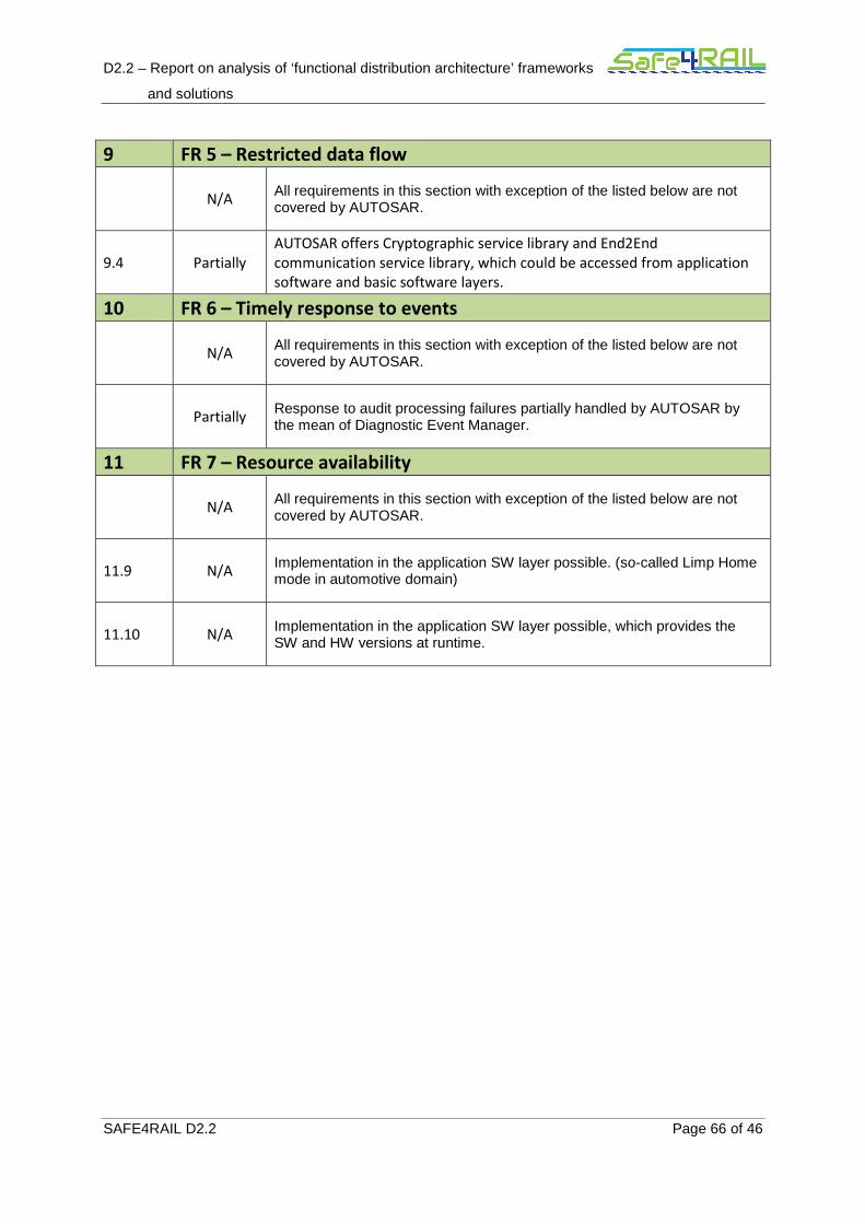
D2.2 – Report on analysis of ‘functional distribution architecture’ frameworks
and solutions
SAFE4RAIL D2.2 Page 66 of 46
9 FR 5 – Restricted data flow
N/A All requirements in this section with exception of the listed below are not covered by AUTOSAR.
9.4 Partially
AUTOSAR offers Cryptographic service library and End2End
communication service library, which could be accessed from application
software and basic software layers.
10 FR 6 – Timely response to events
N/A All requirements in this section with exception of the listed below are not covered by AUTOSAR.
Partially Response to audit processing failures partially handled by AUTOSAR by the mean of Diagnostic Event Manager.
11 FR 7 – Resource availability
N/A All requirements in this section with exception of the listed below are not covered by AUTOSAR.
11.9 N/A Implementation in the application SW layer possible. (so-called Limp Home mode in automotive domain)
11.10 N/A Implementation in the application SW layer possible, which provides the SW and HW versions at runtime.


![D2.2: CERBERO Technical Require- ments (Final version) · (Final version) Lead Beneficiary: IBM Workpackage: WP2 Date: Distribution - Confidentiality: [Public] Abstract: This document](https://img.pdfslide.net/doc/110x75/5f3b3d67884c1230ae7bea9d/d22-cerbero-technical-require-ments-final-version-final-version-lead-beneficiary.jpg)