Embed Size (px)
Citation preview
EUROPEAN COMMISSION SEVENTH FRAMEWORK PROGRAMME
GA No. 610990
Cooperative dynamic formation of platoons for safe and energy-optimized goods transportation
D3.2 Information Model for Platoon Services
Deliverable No. COMPANION D3.2
Deliverable Title Information Model for Platoon Services
Dissemination level Public
Written By Sönke Eilers (OFFIS)
Checked by Sönke Eilers (OFFIS) 2015-09-30
Approved by Magnus Adolfson (Scania) Technical
Coordinator 2015-09-30
Issue date 2015-09-30
Ref. Ares(2015)4042508 - 01/10/2015

D3.2 – Information Model for Platoon Services COMPANION- 610990 Public
2 / 44
History log
Name Status Version Date Summary of actions made
OFFIS Sönke Eilers
Editor 1 22.10.2014 First draft. scheme and descriptions
OFFIS Sönke Eilers
Editor 1.2 09.03.2015 Overall architecture, main flow of information
OFFIS Sönke Eilers
Editor 1.3 01.09.2015 Data models
OFFIS Sönke Eilers
Editor 1.4 10.09.2015 Prepared for first internal review.
SCANIA Sergej Saibel
Contributor
1.4 14.09.2015 Data definitions
OFFIS Sönke Eilers
Editor
1.5 29.09.2015 Overhaul of BPMN diagrams
SCANIA Samuel Wickström
Reviewer 1.6 30.09.2015 Clarification commenting.
OFFIS Sönke Eilers
Editor
1.7 30.09.2015 Incorporated final comments

D3.2 – Information Model for Platoon Services COMPANION- 610990 Public
3/44
Abbreviations 3G Short form of third generation of mobile telecommunications technology
AP Assignment Plan – Plan for the truck with route, speed profile and merge/split points for platooning
ACC Adaptive Cruise Control
BPMN Business Process Model and Notation
CAM Cooperative Awareness Message
CACC Cooperative Automatic Cruise Control
CC Cruise Control
ETA Estimated time of arrival
HMI Human-Machine Interface
MOE Monitoring and Optimization Engine
NDS Navigation Data Standard
RCE Route Calculation Engine
TA Transport Assignment – Assignment issued by the dispatcher with Start, Destination and preferred time of arrival
V2V Vehicle to Vehicle
V2X Vehicle to Infrastructure
WGS84 World Geodetic System 1984

D3.2 – Information Model for Platoon Services COMPANION- 610990 Public
4/44
Executive summary The objective of the COMPANION project is to develop co-operative mobility technologies for supervised vehicle platooning, in order to improve fuel efficiency and safety for goods transport. The potential social and environmental benefits inducted by heavy-duty vehicle platoons (or road trains) have been largely proven. However, until now, the creation, coordination, and operation of such platoons have been mostly neglected. The COMPANION project aims to develop a new energy efficient and user-friendly integrated framework for coordinated driving of heavy-duty vehicles. This document represents the deliverable D3.2 – Information Model for Platoon Services. The document contains the descriptions of the processes and information exchange between
components from the point of view of vehicles, facilities, and systems, according to the scenarios
defined in the deliverable D2.1, the user requirements expressed in the deliverable D 2.3 and the
technical requirements captured in D2.4. Furthermore, the overall component architecture is
described in detail in deliverable D3.1. This component architecture will be sketched in chapter 2 of
the document, a more detailed description of the regarding components and services can be found in
deliverable D3.1.
This deliverable focuses on the refinement of processes described in the use cases of D2.1. These
business processes are described in chapter 3 of this document. To this end, the processes of the use
cases from D2.1 are modeled as business processes, using BPMN, while also referring to the concrete
used services. While a use case captures the mere functionality, the purpose of this document is to
provide a mapping of the processes to the concrete services of the component architecture.
Chapter 4 consists of the data definitions used throughout this document and has mainly the purpose
to serve as a reference section, as these data definitions are mentioned in several places of the
document and to have a central place in this document.
D3.2 – Information Model for Platoon Services COMPANION- 610990 Public
5/44
Content History log 2
Abbreviations 3
Executive summary 4
1. Introduction 7
Platooning 8
About this Document 9
Users and Stakeholders 10
Users of the COMPANION-System 11
Dispatcher 11
Truck Driver 11
Stakeholders of the COMPANION-system 11
Carrier 11
Consignor 11
Consignee 11
Truck Manufacturer 11
Information Providers 12
Society 12
2. Overall Architecture 13
Main Flow of Information 13
3. Main Business Processes 16
Before Trip 16
Before Trip 1 – Add Separate Planned Transport Assignment 16
Before Trip 2 – Assignment of Optimal Route 18
Before Trip 4.1 – Start Trip with Automatic Speed Control 20
Platooning 21
Platooning 1.1 – Automatic Platoon Formation 21
Platooning 2 – Platooning under Normal Conditions 23
Platooning 3 – Emergency Braking 25
Platooning 4 – Vehicle Interferes Platoon 26
Platooning 5 – Platoon Passes Motorway Entrance 27
Platooning 6 – Platoon Passes Motorway Exit 28
Platooning 9 – Truck Leaves Platoon 29
Recalculation 31
Recalculation 1 – New Route due to Deviation from Plan 31
Recalculation 2 – Changed Platooning Possibilities due to Deviation from Plan 33
Recalculation 3 – Delay due to Deviation from Plan 34
D3.2 – Information Model for Platoon Services COMPANION- 610990 Public
6/44
Recalculation 4 – New Route due to Added Transport 35
Recalculation 5 – Changed Platooning Possibilities due to Added Transport 37
4. Data Definitions 38
Transport Assignment 38
Assignment Confirmation 38
Route 39
Request Object 39
Result Object 39
Road Section Object 40
Assignment Plan 42
Fleet State and Vehicle State 43
Fleet State Object 43
Vehicle State Object 43
References 44

D3.2 – Information Model for Platoon Services COMPANION- 610990 Public
7/44
1. Introduction The objective of the COMPANION project is to develop co-operative mobility technologies for
supervised vehicle platooning, see Figure 1-1, in order to improve fuel efficiency and safety for goods
transport. The potential social and environmental benefits inducted by heavy-duty vehicle platoons
(or road trains) have been largely proven. However, until now, the creation, coordination, and
operation of such platoons have been mostly neglected. The companion project aim to develop a new
energy efficient and user-friendly integrated framework to coordinated driving of heavy-duty vehicles.
Figure 1-1 A heavy-duty vehicle platoon
Proposed is a new real-time coordination system, which will define an optimized flow of vehicles in
order to dynamically create, maintain and dissolve platoons according to an online decision-making
mechanism, also taking into account historical and real-time information about the state of the
infrastructure. With such a technology, platoons will no longer be composed just of vehicles with
common origins and destinations, but rather created dynamically on the road, by merging vehicles (or
sub-platoons) that share only parts of their routes.

D3.2 – Information Model for Platoon Services COMPANION- 610990 Public
8/44
Platooning According to the BASt definition1, the levels of automation of the driving task can be classified as
follows:
No Automation—Driver is in complete control of the vehicle.
Driver Assistance—Partial automation of either longitudinal control (e.g., ACC) or lateral control (e.g.,
lane-keeping) while the driver controls the other functions and remains fully engaged in the driving
task.
Partial Automation—Both longitudinal and lateral control are automated, but the level of automation
is sufficiently limited in capability that the driver needs to continuously monitor its behavior and be
prepared to take over control at any time.
High Automation—Both longitudinal and lateral control are automated but at a higher level such that
the driver no longer needs to continuously monitor its behavior and only needs to be prepared to take
over control within a “certain” (currently unspecified) time interval.
Full Automation—The system has a sufficiently high level of automation that when it requests the
driver to regain control (because of a condition it cannot handle), and the driver fails to respond, it can
return to a minimum-risk condition (such as stopping the vehicle) by itself.
The focus of the COMPANION project is to coordinate trucks into platoons on the automation level
“Driver assistance”. The longitudinal control will be automated. The driver will be responsible for
lateral control, steering the vehicle and all other functions in the truck.
1Legal consequences of an increase in vehicle automation http://www.bast.de/DE/FB-F/Publikationen/Download-Publikationen/Downloads/F-legal%20consequences.pdf?__blob=publicationFile

D3.2 – Information Model for Platoon Services COMPANION- 610990 Public
9/44
About this Document This document represents the deliverable D3.2 – Information Model for Platoon Services.
These processes and information models have been derived from:
1. The use scenario and use cases defined in the delivery D2.1 - Potential scenarios for new
platooning concepts [1],
2. The user requirements defined in the delivery D2.3 - Final user requirements [2],
3. The technical requirements defined in the deliverable D2.4 [3],
4. The business requirements defined in the deliverable D2.5 [4],
5. The overall architecture defined in D3.1 [6],
6. Interviews with potential end users.
The flow is illustrated in Figure 1-2. This deliverable along with deliverable D3.1 is essential for the
subsequent refinement of the design of the architecture, implementation, testing and validation of the
actual COMPANION system.
Figure 1-2 Overview of COMPANION deliverables
The document follows the logical structure of deliverable D2.1: “Potential scenarios for new
platooning concepts” and is partitioned in three sections: before trip, platooning and
recalculation.
D2.1
Use Scenario
User, Technical, and Business
D2.3
D2.4
D2.5
D3.1
D3.2
System Architec

D3.2 – Information Model for Platoon Services COMPANION- 610990 Public
10/44
The processes sketched in the use cases are modelled in BPMN 2.0 (Business Process Model and
Notation), which is specified by the Object Management Group (OMG)2 .
Furthermore, the information exchanged between components is described in tables that specify
the parameters, their description and data types.
Users and Stakeholders The users and stakeholders of the COMPANION system were defined in deliverable D2.1 and are shown
in this document for reference. In this document mainly the driver and the dispatcher are concerned,
because they are the users interacting with the COMPANION system.
Users are all parties that interact directly with the system whilst stakeholders are all parties that have
an interest in the system and are directly or indirectly affected by it. The users and stakeholders are
illustrated in Figure 1-3 and described in the following sections.
Figure 1-3 Users and Stakeholders of the COMPANION-system
2 BPMN 2.0 Reference: http://www.omg.org/spec/BPMN/2.0/

D3.2 – Information Model for Platoon Services COMPANION- 610990 Public
11/44
Users of the COMPANION-System
Dispatcher
The dispatcher is responsible for coordination of transports within a carrier company. By
communicating relevant information and tracking the vehicles, the dispatcher assures that the
transports are carried out according to desired service levels at a minimal cost. The COMPANION-
system will support the dispatcher to find an optimal transport plan, with respect to minimal fuel
consumption, for all trucks in the fleet, by means of coordinated platooning.
Truck Driver
The truck driver is responsible for maneuvering the truck from its origin to its destination according to
given time constraints at a minimal cost. The COMPANION-system will support the truck driver in
his/her efforts to minimize the cost of driving the truck from its origin to its destination, by means of
coordinated platooning. The system will help the driver to calculate the route and speed prior to and
during the transport assignment in order to form platoons in a fuel optimal way and to reach the
destination in time.
Stakeholders of the COMPANION-system
Carrier
A carrier is a company transporting goods for a client (e.g. a consignor). The objective of the carrier is
to complete the transport assignments according to agreed time constraints at a minimal cost. The
COMPANION-system will contribute to a lowered total cost of transport with retained level of service,
which will benefit the carrier.
Consignor
Consignor is the party sending a shipment. The consignor has contracted the carrier to transport goods
according to an agreed time constraints and cost. The COMPANION-system will contribute to a
lowered total cost of transport with retained level of service, which will benefit the consignor.
Consignee
The consignee is the person to whom the shipment is to be delivered. The consignee has contracted
the consignor to provide goods at an agreed time and cost. The consignee will be the one determining
the preferred service level (time constraints, flexibility etc), affecting the minimal cost of transport.
The COMPANION-system will contribute to a lowered total cost of transport with retained level of
service, which will benefit the consignee.
Truck Manufacturer
The truck manufacturer will provide the COMPANION-system with information about the
characteristic and current state of the truck required for optimizing the fuel consumption, by
coordinating trucks into platoons. The truck manufacturer will also make use of the information from
the COMPANION-system, by informing the driver or controlling the vehicle according to the speed
recommended by the system.

D3.2 – Information Model for Platoon Services COMPANION- 610990 Public
12/44
Information Providers
Information providers will provide the COMPANION-system with information about the characteristic
and current state of the road infrastructure and traffic situation (weather information, traffic flow
information etc.), required for optimizing the fuel consumption by coordinated platooning.
Society
The COMPANION-system will contribute to reduced environmental impact from transports by
lowering the emission.

D3.2 – Information Model for Platoon Services COMPANION- 610990 Public
13/44
2. Overall Architecture This chapter sketches the overall components architecture of the COMPANION system and the flow
of information for the nominal use case, which is the strategic planning of Assignment Plans for the
vehicles. This document mainly addresses the Route Management Layer of the layered architecture
described in D3.1 - Component Specifications for the Overall Architecture [6], because the focus of
the COMPANION project lies on the off-board plattform for creation and coordination of platoons.
For the sake of clarity, the lower 2 layers of the layered architecture will therefore be addressed in a
cursory fashion.
For further details on the components architecture, please refer to deliverable D3.1 - Component
Specifications for the Overall Architecture.
Figure 2-1 depicts the main components of the overall architecture and the main flow of information
between these components.
Figure 2-1: COMPANION Overall Architecture
Main Flow of Information As the architecture above only captures the components of the system but not how these interact
during the operation of the COMPANION system, it is also vital to model the dynamic part of such
system: processes and the interaction with its users. To this end, the nominal use case of the
strategic planning phase is described here with a sequence diagram, shown in Fel! Hittar inte
referenskälla..

D3.2 – Information Model for Platoon Services COMPANION- 610990 Public
14/44
The nominal use case of the system shows the main flow of information during the strategic planning
phase. The term nominal use case indicates, that the main process is described for the sake of clarity,
without going into detail how to handle how the system should behave, if an error needs to be
handled in this process.
The nominal use case starts with the dispatcher of a company entering a Transport Assignment into a
web-application, which the dispatcher can use with a Web-Browser. The Transport Assignment
consists of all the data needed for the planning of a transport such as start and destination of the
transport, and departure and arrival times.
When the dispatcher chooses to store the Transport Assignment, it is sent to the off-board platform.
The Fleet Manager Service is responsible for storing, managing and updating the Transport
Assignments.
As the Transport Assignment has been submitted to the COMPANION system by the dispatcher, it is
now time to start the optimization process of finding the optimal route, speed profile and other
trucks to platoon with in order to minimize the fuel consumption of the vehicle for this transport.
After the Fleet Manager received and stored a Transport Assignment, it sends the assignment to the
Monitoring and Optimization Engine. The optimization process for an assignment starts with
calculating the initial optimal route, a coarse speed profile and fuel consumption for this single
transport. The Monitoring Engine asks the Route Calculation Engine for the optimal route, which is
then returned to the Monitoring Engine. This route already contains a coarse speed profile. In order
to get a more detailed speed profile for this route, the Monitoring Engine queries the Vehicle and
Fuel-Consumption Model for the traversal time of this transport. In a second query to the Vehicle
and Fuel Consumption Model the Monitoring Engine gets an estimate for the fuel-consumption of
the transport.
With the detailed speed profile and the optimal route for an individual transport, the Monitoring and
Optimization Engine is now able to look for other transports and platooning opportunities for this
transport. The optimization process consists of finding possible transports to platoon with and
subsequently calculating, which combination of trucks to platoons yield in a global minimal fuel
consumption. During the optimization the speed profiles of the trucks have to be adapted so that the
trucks are able to meet on the highway. Furthermore, merge and split points are introduced, which
are the calculated points, where the trucks merge and split from a platoon.
The result of the global optimization in the Monitoring and Optimization Engine is a Platooning Plan
for each truck. This Platooning Plan incorporates the route and speed profile for the vehicle and the
merge and split-points for the according platoons. When the Optimization Engine has calculated the
Platooning Plan, this plan is sent to the Fleet Manager.
The Fleet Manager stores this Platooning Plan and calculates an even finer speed profile for this
transport. The Platooning Plan with this refined speed profile is called Assignment Plan. After the
Fleet Manager calculated the Assignment Plan, this plan is sent to the truck.

D3.2 – Information Model for Platoon Services COMPANION- 610990 Public
15/44
When the truck starts with the transport, the vehicle starts sending its status (position, velocity, etc.)
to the Fleet Manager, which is also responsible for storing the vehicle’s track, meaning the historical
data. Furthermore, the dispatcher can get information about the current state of the transport via
the web interface.
Because the traffic is dynamic and introduces deviations from the Assignment Plan, for example due
to a traffic jam, a recalculation of the Assignment Plan can be triggered by the Monitoring and
Optimization Engine, which gets the information of the current state of a transport from the Fleet
Manager. The next chapter contains a detailed description of processes concerning the strategic
planning, platooning and the recalculation of the Assignment Plan due to unpredicted events.
Figure 2-2: Main Flow of Information during Planning

D3.2 – Information Model for Platoon Services COMPANION- 610990 Public
16/44
3. Main Business Processes This chapter describes the main business processes in the COMPANION system.
The processes are structured in the sections:
Before trip
Platooning
Recalculation
Before Trip This section includes the main business processes concerning the strategic planning. In this planning
phase the dispatcher submits a Transport Assignment to the system and the COMPANION system
looks for other vehicles to platoon with prior to the actual transport. The result of this planning and
optimization process is an Assignment Plan, which consists of an optimal route, fine grained speed
profile, merge points and split points for platooning.
Before Trip 1 – Add Separate Planned Transport Assignment
The use case Before Trip 1 – Add Separate Planned Transport Assignment from deliverable D2.1
describes the use case for the dispatcher submitting a Transport Assignment to the COMPANION
system. Figure 3-1 depicts the according business process of the use case Before Trip 1 modeled in
BPMN. A Transport Assignment contains all data needed for a single transport, for example origin,
destination and planned timed of arrival (see Table 1: Transport Assignment).
The web interface is responsible for handling the access to the Transport Assignment database and
sends the Transport Assignment to the Fleet Manager Service.
The Receiving Transport Assignment process at the Fleet Manager is responsible for checking the
validity of the transport assignment received from the dispatcher. For example, the Earliest Time for
Departure of the Transport Assignment cannot be previous to the current time.
After the Receiving Transport Assignment process has handled the Transport Assignment, the service
sends a Confirm Assignment notification (see Table 2) to the dispatcher. This Confirm Assignment
notification indicates if the assignment was successfully stored at the Fleet Manager. This notification
reports success, if the data set was successfully stored by the Fleet Manager or contains an error
message, which points out what went wrong.

D3.2 – Information Model for Platoon Services COMPANION- 610990 Public
17/44
Figure 3-1: Process of Use Case Before Trip 1 – Add separate planned transport assignment

D3.2 – Information Model for Platoon Services COMPANION- 610990 Public
18/44
Before Trip 2 – Assignment of Optimal Route
A certain time before a transport the Assignment Plan is calculated. This plan consists of the optimal
route, speed profile and merge and split points for platooning.
This is achieved by matching trucks witch overlapping routes together to platoons and adapting their
speed profiles in such a way, that they are able to meet on a highway during a transport.
To this end, a scheduling service selects transports from the Transport Assignment database and
notifies the dispatcher that a certain transport is due. If the dispatcher confirms, that the given
constraints still hold, this Transport Assignment is given to the Monitoring and Optimization Engine,
which calculates in cooperation with the Route Calculation Engine the optimal platooning strategy
for this set of vehicles. The optimal strategy is in the case of the COMPANION system the strategy
with minimal global fuel consumption.
After the optimal route and speed profile for such a set of vehicles has been calculated, the
Assignment Plan is sent to the driver and the truck and stored in a database in the off-board
platform. Both, truck and driver have to send a notification to the dispatcher, that this information
has been received successfully.
The BMPN diagram in Figure 3-2 depicts this business process. Please note, that this diagram
essentially captures the same process as the sequence diagram Fel! Hittar inte referenskälla., but
focuses on the interaction of the users with the system and does not depict all services in detail.

D3.2 – Information Model for Platoon Services COMPANION- 610990 Public
19/44
Figure 3-2: Process of Use Case Before Trip 2 – Assignment of Optimal Route

D3.2 – Information Model for Platoon Services COMPANION- 610990 Public
20/44
Before Trip 4.1 – Start Trip with Automatic Speed Control
The use case Before Trip 4.1 – Start Trip with Automatic Speed Control is addressing the driver
entering the highway and activating the cooperative automatic cruise control (CACC). The business
process for this use case is depicted in Figure 3-3.
Before activating the CACC, the truck driver has to start the trip and drive the truck to a highway.
Only, when the truck is on a highway, the CACC of the vehicle can be activated. The automatic
activation of an automation in a vehicle is not allowed, therefore the driver has to engage the CACC
manually. The automatic speed control follows the speed profile of the Assignment Plan.
Of course the truck has to mind the surrounding traffic when following the speed profile of the
Assignment Plan. This is realized by an arbiter in the CACC that follows the speed profile of the
Assignment Plan if no vehicle is in front of it and adepts the speed of the truck in case another
vehicle is driving in front of it with a slower speed than planned according to the speed profile of the
Assignment Plan.
Figure 3-3: Process of Use Case Before Trip 4.1 – Start Trip with Automatic Speed Control

D3.2 – Information Model for Platoon Services COMPANION- 610990 Public
21/44
Platooning
This section describes the business processes related to the use cases for platooning.
Platooning 1.1 – Automatic Platoon Formation
This use case describes the process of joining a platoon. While the truck joining a platoon is driving to
the merging point, the distance and estimated time to join the platoon is calculated and shown to
the driver.
This information is calculated in the Road Segment Governing Layer of the architecture. The
information exchange between the trucks position and other vehicles of the platoon is taking place
over the internet and the off-board platform.
When the truck is in vicinity of the platoon (~500m for V2V communication) the truck can start to
share information with the platoon via V2V communication. From this point the merging process is
handled by the vehicles.
In vicinity of the platoon the CACC activates the merging process and is automatically closing the gap
to the truck in front it. If the truck is merging from behind of the platoon, the joining truck for
example automatically moves to a predefined distance (for example 15m) to the last truck. When the
platooning distance is reached the state of the controller goes from merging to platooning and it is
shown to the driver that the truck is now platooning.

D3.2 – Information Model for Platoon Services COMPANION- 610990 Public
22/44
Figure 3-4: Process of Use Case Platooning 1.1 – Automatic Platoon Formation

D3.2 – Information Model for Platoon Services COMPANION- 610990 Public
23/44
Platooning 2 – Platooning under Normal Conditions
The use case Platooning 2 – Platooning under Normal Conditions considers the platooning scenario.
Precondition is that vehicles have already merged to a platoon and the distance to each other is held
by the CACC. Trucks are exchanging information via V2V-communication ETSI G5 Standard [5]
(Position, etc.).
Every vehicle reports its state to the Fleet Manager Service in the off-board platform via mobile
communication. The according dispatcher can track the position of the truck he is responsible for in
his HMI Web-Interface. He is not able to see the position of other trucks not belonging to his
company.
Note, that the safe operation of platoons in not depending on a connection to the off-board
platform. The trucks report only telemetry data to the Fleet Manager in the operational phase. Due
to a recalculation of an Assignment Plan an update of the plan may happen, but this is not a safety-
critical event.

D3.2 – Information Model for Platoon Services COMPANION- 610990 Public
24/44
Figure 3-5 Business Process - Platooning under normal Conditions

D3.2 – Information Model for Platoon Services COMPANION- 610990 Public
25/44
Platooning 3 – Emergency Braking
The use case Platooning 3 – Emergency Braking considers heavy braking of a vehicle in the platoon
due to an unforeseen event (for example another vehicle in the lane of the platoon is significantly
slower).
If one of the trucks in the platoon has to brake heavily, the following trucks need to be informed of
this event, in order to brake in time to avoid a collision. The distributed control system signals to all
following trucks in the platoon via V2V communication to brake.
Figure 3-6: Emergency Braking

D3.2 – Information Model for Platoon Services COMPANION- 610990 Public
26/44
Platooning 4 – Vehicle Interferes Platoon
Figure 3-7 depicts the BPMN diagram for the use case Platooning 4 – Vehicle Interferes Platoon.
When the trucks are platooning, an intersecting vehicle poses a potential threat to the safety of the
platoon. The interfering vehicle does not have V2V communication and a CACC matching the one of
the COMPANION system.
In case a vehicle interferes with a platoon, it has to be ensured that a safe distance to the interfering
vehicle is established by the trucks. Also the driver of the truck has to be made aware, that a vehicle
is cutting in. After the interfering vehicle has left the lane, the control of the platoon re-establishes
the nominal platooning distances between the trucks.
Figure 3-7: Vehicle interferes with Platoon

D3.2 – Information Model for Platoon Services COMPANION- 610990 Public
27/44
Platooning 5 – Platoon Passes Motorway Entrance
Figure 3-8 depicts the process of use case Platooning 5 – Platoon Passes Motorway Entrance. When a
platoon is about to pass a highway entrance, the gaps between the trucks in the platoon have to be
increased, to allow for other traffic to change from the highway entrance safely into the lane of the
platoon and then to overtake the platoon. After the platoon has passed the highway entrance and
other traffic has cleared from the platoon, the gaps between the trucks can be decreased to the
nominal platooning distance again.
Figure 3-8 Process for a Platoon passing a highway entrance

D3.2 – Information Model for Platoon Services COMPANION- 610990 Public
28/44
Platooning 6 – Platoon Passes Motorway Exit
Figure 3-9 shows the process of use case Platooning 6 – Platoon Passes Motorway Exit. This process
is analogue to the previous process of a platoon passing a highway entrance. The gaps between the
trucks have to be increased ahead of the highway exit and decreased to the nominal platooning
distance, when other traffic has cleared from the platoon.
Figure 3-9 Process for a Platoon passing a Highway Exit

D3.2 – Information Model for Platoon Services COMPANION- 610990 Public
29/44
Platooning 9 – Truck Leaves Platoon
Figure 3-10 depicts the process of the use case Platooning 9 – Truck Leaves a Platoon. When a driver
comes into the vicinity of a split point - a place where he is about to leave the platoon - the driver is
informed of this upcoming event via the onboard HMI.
When leaving a platoon, the CACC automatically increases the distance to the leading vehicle and the
driver can leave the platoon at a highway exit or highway split.
It is shown to the other drivers that the truck is about to leave the platoon and after splitting from
the platoon the truck follows its individual route.
Figure 3-10 Process of a Truck leaving a Platoon

D3.2 – Information Model for Platoon Services COMPANION- 610990 Public
30/44

D3.2 – Information Model for Platoon Services COMPANION- 610990 Public
31/44
Recalculation This section consists of the processes that include a recalculation of the Assignment Plan during the
transport. A recalculation can be triggered by a deviation from plan, for example due to predicted
and actual traffic jams. Furthermore, a recalculation may affect only parts of the Assignment Plan.
For example it may suffice in some cases to adjust the speed profile of an Assignment Plan, in other
cases it is necessary to recalculate the whole Assignment Plan, including route, speed profile and
platooning parameters.
Recalculation 1 – New Route due to Deviation from Plan
Figure 3-11 shows the process for the recalculation of an Assignment Plan due to a deviation from
the initial plan. The Monitoring Engine is responsible for monitoring an ongoing transport and can
detect, if a transport is able to follow its plan. A deviation from the initial plan can have several
causes: a predicted traffic jam, adverse weather conditions, road works, etc.
When the Monitoring Engine detects that the truck will not be able to follow its current plan, the
Monitoring Engine triggers a recalculation of the Assignment Plan for the vehicle. The Fleet Manager
stores the new Assignment Plan and sends it to the truck.

D3.2 – Information Model for Platoon Services COMPANION- 610990 Public
32/44
Figure 3-11 Process of a recalculation due to a deviation from the Assignment Plan

D3.2 – Information Model for Platoon Services COMPANION- 610990 Public
33/44
Recalculation 2 – Changed Platooning Possibilities due to Deviation from Plan
Figure 3-12 depicts the process for new platooning possibilities due to a deviation from plan. This
process is very similar to the previous process but in this case only a new speed profile and
platooning parameters have to be calculated.
The Monitoring and Optimization Engine detects that the truck is not able to follow its intended
speed profile and will miss its planned opportunities to platoon. Therefore, the Monitoring and
Optimization Engine has to check for new platooning opportunities and transmit the new merge and
split points to the truck.
Figure 3-12 Process for new platooning possibilities due to deviation from plan
D3.2 – Information Model for Platoon Services COMPANION- 610990 Public
34/44
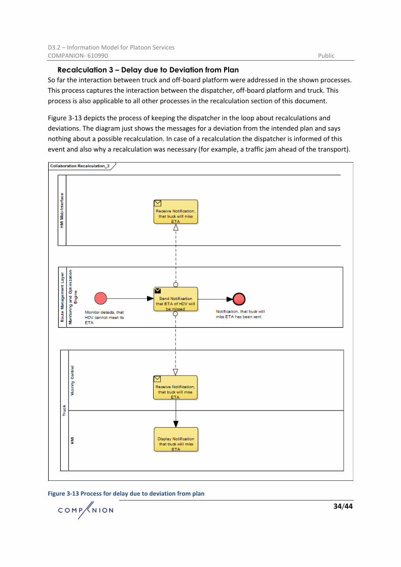
Recalculation 3 – Delay due to Deviation from Plan
So far the interaction between truck and off-board platform were addressed in the shown processes.
This process captures the interaction between the dispatcher, off-board platform and truck. This
process is also applicable to all other processes in the recalculation section of this document.
Figure 3-13 depicts the process of keeping the dispatcher in the loop about recalculations and
deviations. The diagram just shows the messages for a deviation from the intended plan and says
nothing about a possible recalculation. In case of a recalculation the dispatcher is informed of this
event and also why a recalculation was necessary (for example, a traffic jam ahead of the transport).
Figure 3-13 Process for delay due to deviation from plan

D3.2 – Information Model for Platoon Services COMPANION- 610990 Public
35/44
Recalculation 4 – New Route due to Added Transport
Figure 3-14 shows the process for a recalculation that is triggered by an added transport while
another transport is already on the road. This process is also similar to the previous recalculation
processes and only the cause for the recalculation has changed.
Supposing a transport is already on the road and a dispatcher chooses to submit an urgent Transport
Assignment to the system, that is about to start, the Monitoring and Optimization Engine can take
transports into consideration that are already on the road. This new optimization run can find a new
optimal plan for transports that are already taking place and adapt the route, speed profile and
platooning parameters.
Figure 3-14 Process for a new route due to an added transport

D3.2 – Information Model for Platoon Services COMPANION- 610990 Public
36/44

D3.2 – Information Model for Platoon Services COMPANION- 610990 Public
37/44
Recalculation 5 – Changed Platooning Possibilities due to Added Transport
This process is a slight variation from the previous recalculation of an Assignment Plan. As before, the
recalculation is triggered by an added Transport Assignment while a transport is already on the road.
In the previous recalculation the optimization also calculated a new route for the initial transport. In
this process the route is staying the same, but the speed profile and platooning parameters of the
initial transport have to be adapted due to the added transport, as the platooning possibilities
change for the transport that is already on the road.
Figure 3-15: Process for changed platooning possibilities due to an added transport

D3.2 – Information Model for Platoon Services COMPANION- 610990 Public
38/44
4. Data Definitions In this section the most common used data definitions used in the COMPANION system are
described. This section is meant for reference in order to have a central place in the document for
the data definitions.
Transport Assignment The Transport Assignment is the main object, when a dispatcher is submitting a transport to the
system. It contains all information needed for the subsequent services that are involved in the
strategic planning process.
Table 1: Transport Assignment
Parameter Description Data Type
Transport Assignment ID Automatically assigned by the backend when receiving an assignment.
long
Vehicle ID ID of the vehicle. long
Total weight The weight of the freight. int [kg]
Earliest Departure Time Date and time for the earliest departure of the truck.
{Date: YYYY-MM-DD, Time: hh:mm:ss}
Latest Departure Time Date and time for the latest departure of the truck.
{Date: YYYY-MM-DD, Time: hh:mm:ss}
Earliest Arrival Time Date and time for the earliest arrival of the truck.
{Date: YYYY-MM-DD, Time: hh:mm:ss}
Latest Arrival Time Date and time for the latest arrival of the truck.
{Date: YYYY-MM-DD, Time: hh:mm:ss}
Origin Start location of the transport, usually not at the consigner, as the truck starts its trip from a different location (logistics company or last consignee). Reference-System: WGS84
{double Longitude, double Latitude}
Destination The location of the consignee. Reference-System: WGS84
{double Longitude, double Latitude}
Assignment Confirmation
Table 2: Assignment Confirmation
Parameter Description Data Type
TransportAssignmentID The ID of the transport assignment. long TransportAssignmentID
ConfirmationStatus Indicates, whether the transport assignment was successfully stored in the database.
{Successful, Canceled, ErrorCode}

D3.2 – Information Model for Platoon Services COMPANION- 610990 Public
39/44
Route The following objects describe the request object to the Route Calculation Engine and the result
object. The Request Object contains the parameters that are needed by the Route Calculation Engine
to search for an eco-optimal route.
The Result Object, the actual route, returns a route from the start to the destination and consists of a
list of Road Section Objects. The properties of the Road Section Object are also described here.
Request Object
The Request object contains all data needed by the RCE to calculate a route.
Attribute Datatype Description
start WGS84Coord The wgs84- coordinates of the route start
destination WGS84Coord The wgs84- coordinates of the route destination
departure int64
The earliest possible time of departure(in number of seconds since 1970-01-01T00:00:00Z) in UTC
arrival int64
The latest possible time of arrival(in number of seconds since 1970-01-01T00:00:00Z) in UTC
TruckWeightInMetricTons float The weight of the truck in metric tons used for consumption-calculations
maxVelocityInKmH float The maximum velocity the truck will drive [km/h]
Result Object
The Result Object contains the data defining the calculated route.
Attribute Datatype Description Derived from
sections List<RoadSection>
the ordered list of roadsections representing the requested route
Based on the link within the NDS map
lengthInMeters float the length of the complete route in meters
sum of the lenght of the links of the resulting route in the nds map
durationInSeconds int32 the duration of the route-travel in seconds
lengthInMeters and maxVelocityInKmH

D3.2 – Information Model for Platoon Services COMPANION- 610990 Public
40/44
eta int64
the estimated time of arrival at the destination in unix-time (seconds since Thursday, 1 January 1970) in UTC
departure int64
the estimated time of departure at the start (in number of seconds since 1970-01-01T00:00:00Z) in UTC
departure of the Request
minVelocityInKmH float
the minimum velocity on this route in km/h to reach the destination in time
maxVelocityInKmH and the arrival time of the Request
maxVelocityInKmH float
the maximum velocity on this route based on the vehicle-data, speedlimits, weather ,etc.
static map data (e.g. historical speed profiles, average speeds, speedlimits),maxVelocityInKmH in Request and live traffic-information
Road Section Object
The underlying NDS map uses sections of roads called links. These are the smallest parts used to
describe the geographic location of the route. Each Road Section Object represents a NDS link.
Attribute Datatype Description Derived from
geometry List<WGS84Coord>
The linear-geometry represented by a ordered list of WGS-84-coordinates
Geometry of the NDS link
roadName string The road name Roadname or-number of the NDS link
lengthInMeters float The length in meters of this link
Length of the NDS link
altitudeDifferenceInMeters float The altitude difference between start and end of the link
Length and average slope of the NDS link

D3.2 – Information Model for Platoon Services COMPANION- 610990 Public
41/44
eta int64
The estimated time of arrival at the start of the link (in number of seconds since 1970-01-01T00:00:00Z) in UTC
Currently based on maxVelocityInKmH
minVelocityInKmH float
The minimum velocity on this link in km/h to reach the destination in time
Based on the maxVelocityInKmH and the arrival time of the Request distance to target, speed on other links
maxVelocityInKmH float
The maximum velocity on this link based on the vehicle-data, speedlimits, weather ,etc.
static map data (e.g. historical speed profiles, average speeds, speedlimits),maxVelocityInKmH in Request and live traffic-information
durationInSeconds int32 The duration of the link-travel in seconds
lenght of the NDS link and maxVelocityInKmH
directedLinkId int64
The nds link id. The direction is ecoded in the sign. a positive id means positive direction, a negative id means negative direction.
Unique id in the NDS map

D3.2 – Information Model for Platoon Services COMPANION- 610990 Public
42/44
Assignment Plan The Assignment Plan is the actual plan sent to the truck. It contains besides the route a fine grained
speed profile and the merge/split points needed for platooning.
Attribute Datatype Description Origin
Waypoint Origin longitude and latitude
Destination
Waypoint Destination longitude and latitude
Load
int Cargo weight, kg
Planned departure time
DateTime Planned departure time, UTC
Planned arrival time
DateTime Planned arrival time, UTC
Route
List<Waypoint> Planned vehicle route
Speed profile
List<Waypoint, Speed> Planned vehicle speed profile
Planned platooning merge/split segments
List<Segment> List of segments for merge/split platoons

D3.2 – Information Model for Platoon Services COMPANION- 610990 Public
43/44
Fleet State and Vehicle State The Fleet State is a list of Vehicle State objects. The Vehicle State object describes the current
position (Longitude/Latitude) and if applicable a deviation from the current Assignment Plan.
Fleet State Object
Attribute Datatype Description
VehicleStateList List<VehicleState> Vehicle state list
Vehicle State Object
Attribute Datatype Description
VehicleId long Vehicle ID
Latitude decimal Vehicle Latitude
Longitude decimal Vehicle Longitude
CompanionsVehicleIds List<long> List of the currently platooning vehicles, in order
DeviationTime long Deviation in sec, +/-
Deviated bool True then deviated

D3.2 – Information Model for Platoon Services COMPANION- 610990 Public
44/44
References
[1] COMPANION, "Deliverable D2.1 Potential scenarios for new platooning concepts," 2014.
[2] COMPANION, "Deliverable D2.3 Final User Requirements," 2014.
[3] COMPANION, "Deliverable D2.4 Technical Requirements," 2015.
[4] COMPANION, "Deliverable D2.5 Business Requirements and Business Opportunities," 2015.
[5] ETSI, "Intelligent Transport Systems (ITS) Vehicular Communications; Basic Set of Applications;
Part 2: Specification of Cooperative Awareness Basic Service," ETSI, 2014.
[6] COMPANION, "Deliverable D3.1 Component Specifications for the Overall Architecture," 2015.
[7] COMPANION, "Deliverable D4.3 Vehicle Models for Fuel Consumption," 2015.
[8] COMPANION, "Deliverable D5.1 Report on fuel-efficient Route Calculation," 2015.