Embed Size (px)
Citation preview
D32x/XD30
Remote Display
Manual
D300-601-200
Copyright
All Rights Reserved. No part of this document may be copied, reproduced, republished, uploaded, posted, transmitted, distributed, stored in or introduced into a retrieval system in any form, or by any
means (electronic, mechanical, photocopying, recording or otherwise) whatsoever without prior written permission of Rinstrum Pty Ltd.
Disclaimer
Rinstrum Pty Ltd reserves the right to make changes to the products contained in this manual in order to improve design, performance or
reliability.
The information in this manual is believed to be accurate in all respects at the time of publication, but is subject to change without
notice. Rinstrum Pty Ltd assumes no responsibility for any errors or omissions and disclaims responsibility for any consequences
resulting from the use of the information provided herein.
Remote Display Installation Manual – Software Version 4.x
D300-602-202 Page 3
Table of Contents
f Contents 1. INTRODUCTION ........................................................... 4
1.1. Approvals .............................................................. 4
1.2. Features ................................................................ 4
1.3. Document Conventions ......................................... 4
2. SPECIFICATIONS ......................................................... 5
2.1. D32x Version ......................................................... 5
2.2. XD30 Version ........................................................ 6
3. WARNINGS AND SAFETY ........................................... 7
3.1. General .................................................................. 7
3.2. Electrical Safety ..................................................... 7
3.3. Cleaning ................................................................ 7
4. INSTALLATION ............................................................. 8
4.1. General Setup Information..................................... 8
4.2. Panel Mounting (D32x Only) .................................. 8
4.3. Cable Connections ................................................ 9
4.4. DC Power .............................................................. 9
4.5. D32x RS-232 Serial Auxiliary Connection ........... 10
4.6. XD30 RS-232 Serial Auxiliary Connection ........... 12
4.7. Cable Shield Connection and Earthing ................ 14
5. CONFIGURATION ....................................................... 15
5.1. Baud (Serial Baud Rate) ...................................... 15
5.2. Delimiters ............................................................ 15
5.3. Address ............................................................... 15
5.4. Formats ............................................................... 16
6. DIAGNOSTIC ERRORS .............................................. 44
Remote Display Installation Manual – Software Version 4.x
Page 4 D300-602-202
1. Introduction
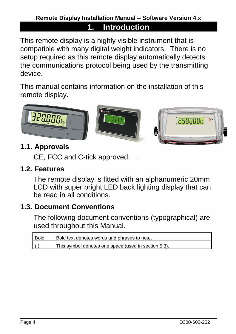
This remote display is a highly visible instrument that is compatible with many digital weight indicators. There is no setup required as this remote display automatically detects the communications protocol being used by the transmitting device.
This manual contains information on the installation of this remote display.
1.1. Approvals
CE, FCC and C-tick approved. +
1.2. Features
The remote display is fitted with an alphanumeric 20mm LCD with super bright LED back lighting display that can be read in all conditions.
1.3. Document Conventions
The following document conventions (typographical) are used throughout this Manual.
Bold Bold text denotes words and phrases to note.
( ) This symbol denotes one space (used in section 5.3).

Remote Display Installation Manual – Software Version 4.x
D300-602-202 Page 5
2. Specifications
2.1. D32x Version Approvals
C-Tick, CE & FCC
Performance
Operating Environment
Temperature: –10 to +50C ambient, Humidity: <90% non-condensing, Storage: -
20 to 50 C ambient, IP65 when panel mounted or IP65 rear boot fitted.
Display
Display Type 20mm LCD display; LED backlight
Number Digits 6
Digit Size 20mm
Plastic Panel Version
Unit Dim 160(W) x 75(H) x 30(D) mm
Pack Weight 0.34kg (Panel Mount)
Case Materials Plastic Version: ABS, Silicon Rubber, Nylon, Acrylic (no halogen used)
Stainless Steel Version
Unit Dim 200(W) x 115(H) x 30(D) mm
Pack Weight 0.49kg (Panel Mount)
Case Materials Stainless Steel
Power Input
Standard Input 4.8 to 24VDC (2.5VA max)
Variants AC AC Plug Pack: minimum output 12VDC 0.5A
Features
Compatibility Compatibility with most indicators
Setup Auto-Detecting Setup
Characters Numeric and semi-alpha characters
Annunciators 3 Annunciators
Serial Input RS232
Selectable Address Select between address 01 and 02
Remote Display Installation Manual – Software Version 4.x
Page 6 D300-602-202
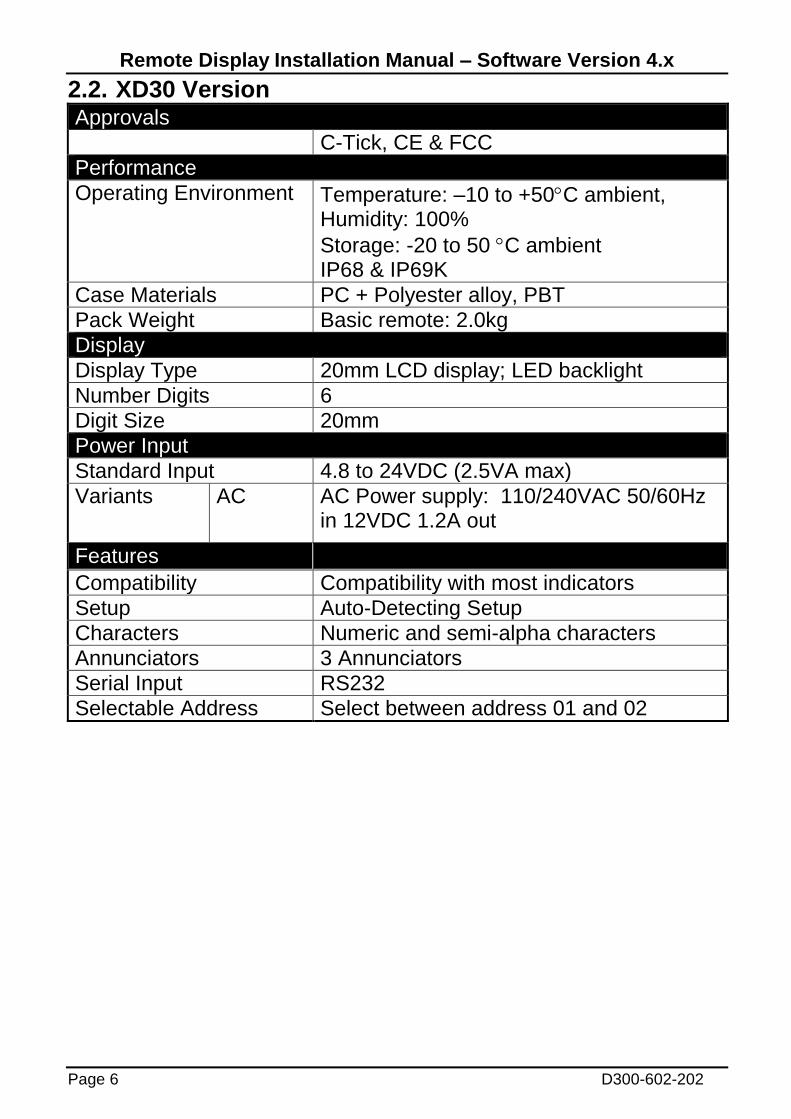
2.2. XD30 Version Approvals
C-Tick, CE & FCC
Performance
Operating Environment Temperature: –10 to +50C ambient, Humidity: 100%
Storage: -20 to 50 C ambient IP68 & IP69K
Case Materials PC + Polyester alloy, PBT
Pack Weight Basic remote: 2.0kg
Display
Display Type 20mm LCD display; LED backlight
Number Digits 6
Digit Size 20mm
Power Input
Standard Input 4.8 to 24VDC (2.5VA max)
Variants AC AC Power supply: 110/240VAC 50/60Hz in 12VDC 1.2A out
Features
Compatibility Compatibility with most indicators
Setup Auto-Detecting Setup
Characters Numeric and semi-alpha characters
Annunciators 3 Annunciators
Serial Input RS232
Selectable Address Select between address 01 and 02

Remote Display Installation Manual – Software Version 4.x
D300-602-202 Page 7
3. Warnings and Safety
3.1. General
Instrument not to be subject to shock, excessive vibration or extremes of temperature; before or after installation.
Inputs are protected against electrical interference, but excessive levels of electro-magnetic radiation and RFI may affect operation.
For full EMC or for RFI immunity, termination of the cable shields and correct earthing of the instrument is essential.
Instrument is sensitive to excessive electrical noise and should be installed well away from any power or switching circuits.
3.2. Electrical Safety
For your protection all mains electrical hardware must be rated to the environmental conditions of use.
Pluggable equipment must be installed near an easily accessible power socket outlet.
To avoid the possibility of electric shock or damage to the instrument, always switch off or isolate the instrument from the power supply before maintenance is carried out.
3.3. Cleaning
• To maintain the D32x version, never use harsh abrasive cleaners or solvents. Wipe the instrument
with a soft cloth slightly dampened with warm soapy water.
• The XD30 has been designed for high-pressure, high temperature (80°C) wash-down environments. However long periods of focused pressure at a close range will damage the casing. Casing is chemical resistant.
Remote Display Installation Manual – Software Version 4.x
Page 8 D300-602-202
4. Installation
4.1. General Setup Information
The following steps are required to set up the remote display.
• Inspect instrument to ensure good condition.
• Ensure mounting options and connectors are available.
• Use connection diagram to wire up power and serial cables as required.
• Then D32x remote display can be panel mounted. Use the "Panel Drilling Template" provided for hole locations. The panel mounting screws are also used to attach desk/wall brackets or the stainless steel rear housing accessories.
• Connect the serial and power cables to the instrument. If using an RS-232 to RS-485 converter, connect the converter between the serial cable and the remote display serial port connector.
• Set the transmitting device to 9600 or 19200 baud and select the preferred output format for that instrument.
4.2. Panel Mounting (D32x Only)
The simplest way to mount the instrument is to use the drill template supplied. The template indicates positions for the drill holes for the two 4mm mounting screws through the panel. Also displayed on the template is the position of the rectangular hole that should be cut to allow for the connection of cables. The drill template supplied with the indicator allows for front or rear machining of the panel.

Remote Display Installation Manual – Software Version 4.x
D300-602-202 Page 9
4.3. Cable Connections
4.3.1. D32x Version
All cable connections are made to the rear of the instrument using screwless terminals. Wires must be stripped of insulation by at least 10mm.
To install, carefully depress the orange lever beside the terminal required and push the wire into the hole. Release the lever and pull gently on the wire to ensure it is securely trapped in the terminal. It is not necessary to tin the ends of the wire with solder or to add crimp ferrules to the wires, but these techniques are also compatible with the terminals and may make for a neater job.
Warning: Care should be taken when depressing the levers on the screwless connectors to prevent sideways movement and possible damage. Use only appropriate
tools (eg. flathead screwdriver). Do not use sharp instruments (eg. pens).
4.3.2. XD30 Version
All cable connections are made to the rear of the instrument using pluggable screw terminals. It is not necessary to tin the ends of the wire with solder or to add crimp ferrules to the wires, however, these techniques are also compatible with the terminals and may ultimately make for a neater job.
4.4. DC Power
The DC supply need not be regulated, provided that it is free of excessive electrical noise and sudden transients.The instrument can be operated from a high quality plug-pack as long as there is sufficient capacity to drive it.
Remote Display Installation Manual – Software Version 4.x
Page 10 D300-602-202
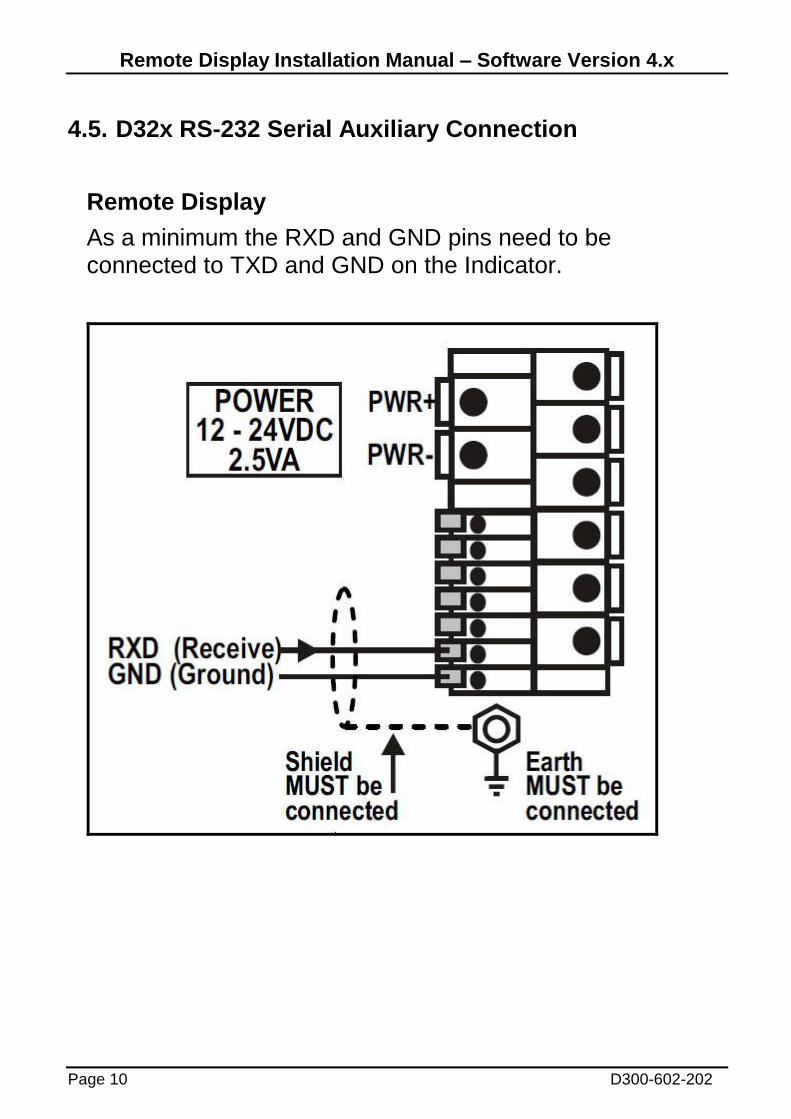
4.5. D32x RS-232 Serial Auxiliary Connection
Remote Display
As a minimum the RXD and GND pins need to be connected to TXD and GND on the Indicator.
Remote Display Installation Manual – Software Version 4.x
D300-602-202 Page 11
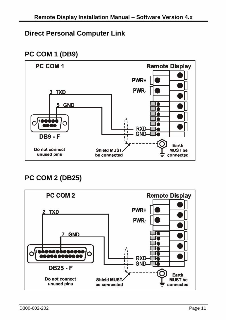
Direct Personal Computer Link
PC COM 1 (DB9)
PC COM 2 (DB25)
Remote Display Installation Manual – Software Version 4.x
Page 12 D300-602-202
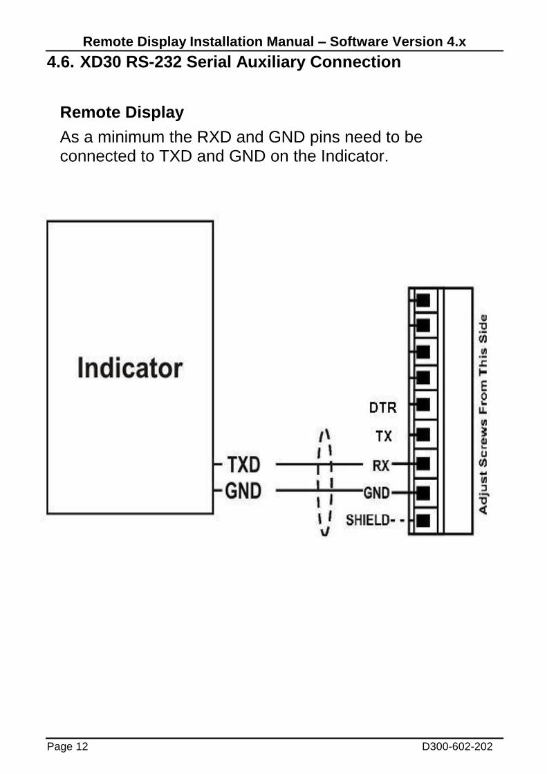
4.6. XD30 RS-232 Serial Auxiliary Connection
Remote Display
As a minimum the RXD and GND pins need to be connected to TXD and GND on the Indicator.
Remote Display Installation Manual – Software Version 4.x
D300-602-202 Page 13
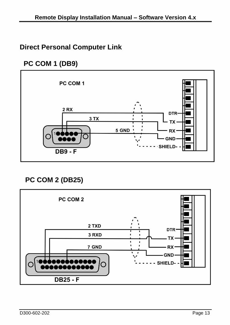
Direct Personal Computer Link
PC COM 1 (DB9)
PC COM 2 (DB25)
Remote Display Installation Manual – Software Version 4.x
Page 14 D300-602-202
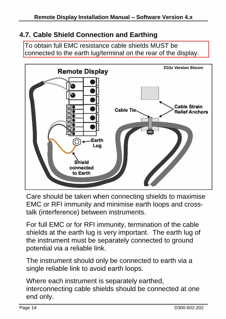
4.7. Cable Shield Connection and Earthing
To obtain full EMC resistance cable shields MUST be connected to the earth lug/terminal on the rear of the display.
Care should be taken when connecting shields to maximise EMC or RFI immunity and minimise earth loops and cross-talk (interference) between instruments.
For full EMC or for RFI immunity, termination of the cable shields at the earth lug is very important. The earth lug of the instrument must be separately connected to ground potential via a reliable link.
The instrument should only be connected to earth via a single reliable link to avoid earth loops.
Where each instrument is separately earthed, interconnecting cable shields should be connected at one end only.

Remote Display Installation Manual – Software Version 4.x
D300-602-202 Page 15
5. Configuration
5.1. Baud (Serial Baud Rate)
Baud rate, parity and data bits are automatically detected. The baud rate can be 9600 or 19200. Parity and data bits supported are:
Parity Data bits Examples Description
(N)one 8 N81, N82 No parity, 8 data bits, 1 or 2 stop bits
(E)ven 7 E71, E72 Even parity, 7 data bits, 1 or 2 stop bits
(O)dd 7 O71, O72 Odd parity, 7 data bits, 1 or 2 stop bits
(M)ark 7 M71, M72 Mark parity, 7 data bits, 1 or 2 stop bits
(S)pace 7 S71, S72 Space parity, 7 data bits, 1 or 2 stop bits
5.2. Delimiters
The instrument responds to any string that ends with the following:
CRLF (ASCII 013, 010), or
ENQ (ASCII 05), or
any string that starts with STX (ASCII 02) and ends with ETX (ASCII 03).
5.3. Address The instrument has a default address of 01 however the address can be set to 02 on the DX30 by connecting the TXD output to the DTR input, or on the D32X by connecting the 2 pins above RXD. Most protocols are not addressed so this is usually not necessary.
Remote Display Installation Manual – Software Version 4.x
Page 16 D300-602-202
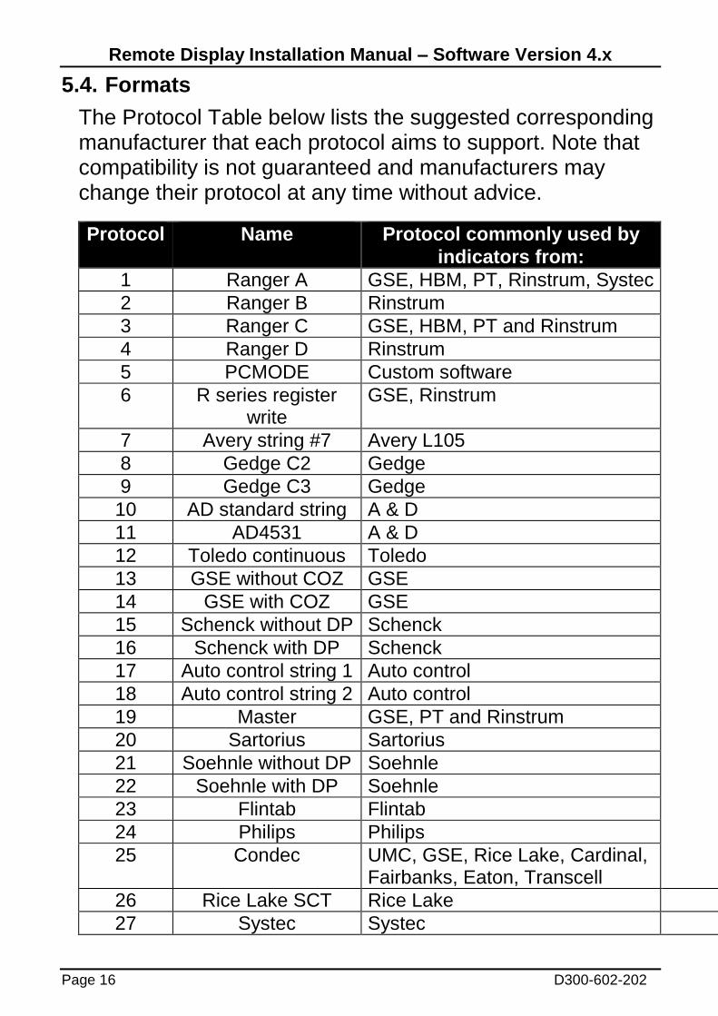
5.4. Formats
The Protocol Table below lists the suggested corresponding manufacturer that each protocol aims to support. Note that compatibility is not guaranteed and manufacturers may change their protocol at any time without advice.
Protocol
Name
Protocol commonly used by
indicators from:
1 Ranger A GSE, HBM, PT, Rinstrum, Systec
2 Ranger B Rinstrum
3 Ranger C GSE, HBM, PT and Rinstrum
4 Ranger D Rinstrum
5 PCMODE Custom software
6 R series register write
GSE, Rinstrum
7 Avery string #7 Avery L105
8 Gedge C2 Gedge
9 Gedge C3 Gedge
10 AD standard string A & D
11 AD4531 A & D
12 Toledo continuous Toledo
13 GSE without COZ GSE
14 GSE with COZ GSE
15 Schenck without DP Schenck
16 Schenck with DP Schenck
17 Auto control string 1 Auto control
18 Auto control string 2 Auto control
19 Master GSE, PT and Rinstrum
20 Sartorius Sartorius
21 Soehnle without DP Soehnle
22 Soehnle with DP Soehnle
23 Flintab Flintab
24 Philips Philips
25 Condec UMC, GSE, Rice Lake, Cardinal, Fairbanks, Eaton, Transcell
26 Rice Lake SCT Rice Lake
27 Systec Systec
Remote Display Installation Manual – Software Version 4.x
D300-602-202 Page 17
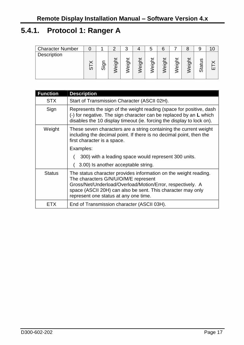
5.4.1. Protocol 1: Ranger A
Character Number 0 1 2 3 4 5 6 7 8 9 10
Description
ST
X
Sig
n
We
igh
t
We
igh
t
We
igh
t
We
igh
t
We
igh
t
We
igh
t
We
igh
t
Sta
tus
ET
X
Function Description
STX Start of Transmission Character (ASCII 02H).
Sign Represents the sign of the weight reading (space for positive, dash
(-) for negative. The sign character can be replaced by an L which disables the 10 display timeout (ie. forcing the display to lock on).
Weight These seven characters are a string containing the current weight including the decimal point. If there is no decimal point, then the first character is a space.
Examples:
( 300) with a leading space would represent 300 units.
( 3.00) Is another acceptable string.
Status The status character provides information on the weight reading. The characters G/N/U/O/M/E represent Gross/Net/Underload/Overload/Motion/Error, respectively. A space (ASCII 20H) can also be sent. This character may only represent one status at any one time.
ETX End of Transmission character (ASCII 03H).
Remote Display Installation Manual – Software Version 4.x
Page 18 D300-602-202
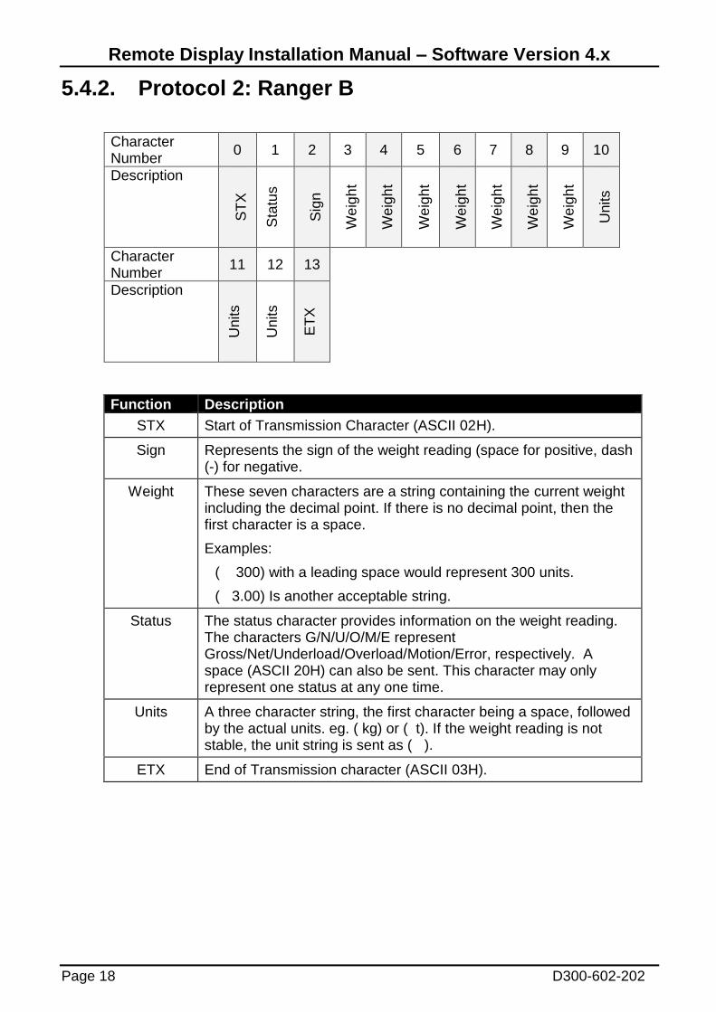
5.4.2. Protocol 2: Ranger B
Character Number
0 1 2 3 4 5 6 7 8 9 10
Description
ST
X
Sta
tus
Sig
n
We
igh
t
We
igh
t
We
igh
t
We
igh
t
We
igh
t
We
igh
t
We
igh
t
Units
Character Number
11 12 13
Description
Units
Units
ET
X
Function Description
STX Start of Transmission Character (ASCII 02H).
Sign Represents the sign of the weight reading (space for positive, dash (-) for negative.
Weight These seven characters are a string containing the current weight including the decimal point. If there is no decimal point, then the first character is a space.
Examples:
( 300) with a leading space would represent 300 units.
( 3.00) Is another acceptable string.
Status The status character provides information on the weight reading. The characters G/N/U/O/M/E represent Gross/Net/Underload/Overload/Motion/Error, respectively. A space (ASCII 20H) can also be sent. This character may only represent one status at any one time.
Units A three character string, the first character being a space, followed by the actual units. eg. ( kg) or ( t). If the weight reading is not stable, the unit string is sent as ( ).
ETX End of Transmission character (ASCII 03H).
Remote Display Installation Manual – Software Version 4.x
D300-602-202 Page 19
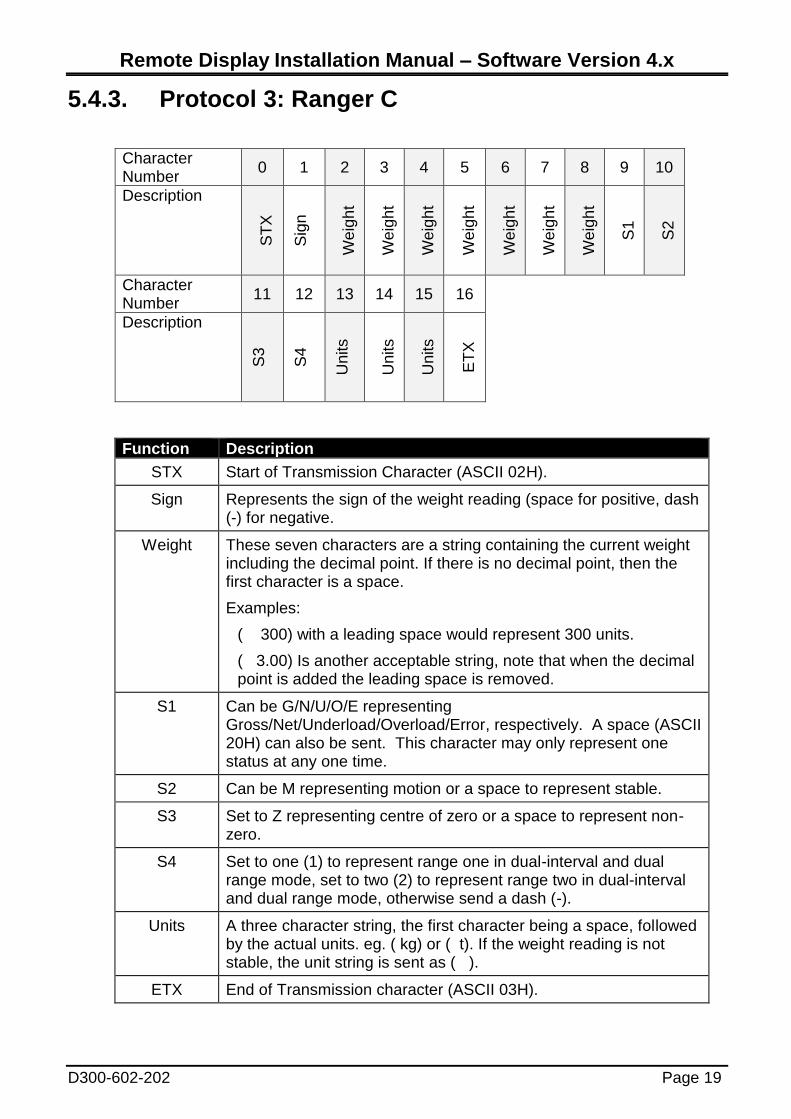
5.4.3. Protocol 3: Ranger C
Character Number
0 1 2 3 4 5 6 7 8 9 10
Description
ST
X
Sig
n
We
igh
t
We
igh
t
We
igh
t
We
igh
t
We
igh
t
We
igh
t
We
igh
t
S1
S2
Character Number
11 12 13 14 15 16
Description
S3
S4
Units
Units
Units
ET
X
Function Description
STX Start of Transmission Character (ASCII 02H).
Sign Represents the sign of the weight reading (space for positive, dash (-) for negative.
Weight These seven characters are a string containing the current weight including the decimal point. If there is no decimal point, then the first character is a space.
Examples:
( 300) with a leading space would represent 300 units.
( 3.00) Is another acceptable string, note that when the decimal point is added the leading space is removed.
S1 Can be G/N/U/O/E representing Gross/Net/Underload/Overload/Error, respectively. A space (ASCII 20H) can also be sent. This character may only represent one status at any one time.
S2 Can be M representing motion or a space to represent stable.
S3 Set to Z representing centre of zero or a space to represent non-zero.
S4 Set to one (1) to represent range one in dual-interval and dual range mode, set to two (2) to represent range two in dual-interval and dual range mode, otherwise send a dash (-).
Units A three character string, the first character being a space, followed by the actual units. eg. ( kg) or ( t). If the weight reading is not stable, the unit string is sent as ( ).
ETX End of Transmission character (ASCII 03H).
Remote Display Installation Manual – Software Version 4.x
Page 20 D300-602-202
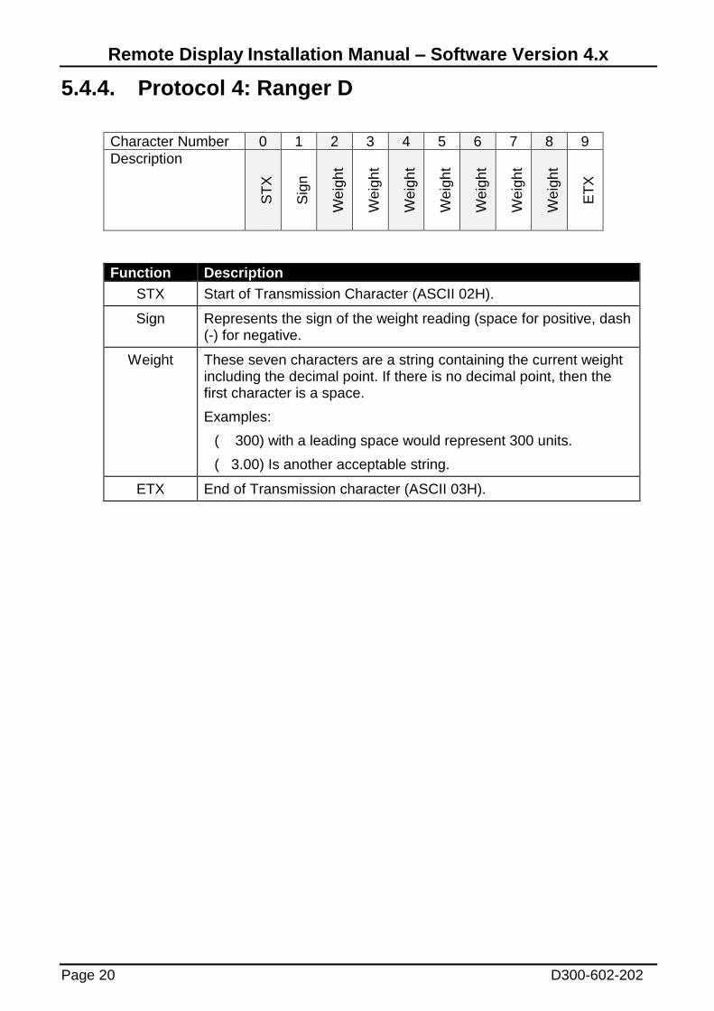
5.4.4. Protocol 4: Ranger D
Character Number 0 1 2 3 4 5 6 7 8 9
Description
ST
X
Sig
n
We
igh
t
We
igh
t
We
igh
t
We
igh
t
We
igh
t
We
igh
t
We
igh
t
ET
X
Function Description
STX Start of Transmission Character (ASCII 02H).
Sign Represents the sign of the weight reading (space for positive, dash (-) for negative.
Weight These seven characters are a string containing the current weight including the decimal point. If there is no decimal point, then the first character is a space.
Examples:
( 300) with a leading space would represent 300 units.
( 3.00) Is another acceptable string.
ETX End of Transmission character (ASCII 03H).
Remote Display Installation Manual – Software Version 4.x
D300-602-202 Page 21
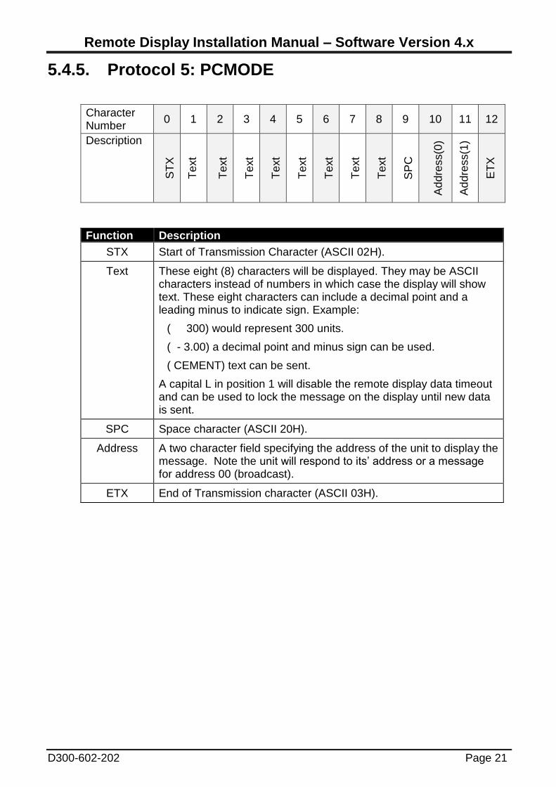
5.4.5. Protocol 5: PCMODE
Character Number
0 1 2 3 4 5 6 7 8 9 10 11 12
Description
ST
X
Te
xt
Te
xt
Te
xt
Te
xt
Te
xt
Te
xt
Te
xt
Te
xt
SP
C
Ad
dre
ss(0
)
Ad
dre
ss(1
)
ET
X
Function Description
STX Start of Transmission Character (ASCII 02H).
Text These eight (8) characters will be displayed. They may be ASCII characters instead of numbers in which case the display will show text. These eight characters can include a decimal point and a leading minus to indicate sign. Example:
( 300) would represent 300 units.
( - 3.00) a decimal point and minus sign can be used.
( CEMENT) text can be sent.
A capital L in position 1 will disable the remote display data timeout and can be used to lock the message on the display until new data is sent.
SPC Space character (ASCII 20H).
Address A two character field specifying the address of the unit to display the message. Note the unit will respond to its’ address or a message for address 00 (broadcast).
ETX End of Transmission character (ASCII 03H).

Remote Display Installation Manual – Software Version 4.x
Page 22 D300-602-202
5.4.6. Protocol 6: R Series Register Write
Character Number
0 1 2 3 4 5 6 7 8 9 10 11 12
Description
Ad
dre
ss(0
)
Ad
dre
ss(1
)
Com
ma
nd
(0)
Com
ma
nd
(1)
Reg
iste
r(0
)
Reg
iste
r(1
)
Reg
iste
r(2
)
Reg
iste
r(3
)
Co
lon
Data
(0)
Data
(1)
Data
(2)
Data
(3)
Character Number
13 14 15 16 17 18
Description
Data
(4)
Data
(5)
Data
(6)
Data
(7)
Te
rmin
ato
r
(0)
Te
rmin
ato
r
(1)
Function Description
Address A two character field specifying the address of the unit to display the message. Note the unit will respond to its’ address or a message for address 00 (broadcast).
Command(0-1) Must be 12 (ASCII 31H, ASCII 32H).
Register(0-3) Must be 000E (ASCII 30H, ASCII 30H, ASCII 30H, ASCII 45H).
Colon This byte must be a colon (ASCII 3AH).
Data(0-7) This is the string to be displayed on the Remote Display and may consist of text and or numbers.
Terminator(0-1) These two characters signify the end of the signal and are represented by a carriage return and then a line feed or CRLF (ASCII 0DH, ASCII 0AH).
Note: When using this protocol the display timeout is disabled, which means that the message will remain on the display until new data is sent.
Remote Display Installation Manual – Software Version 4.x
D300-602-202 Page 23
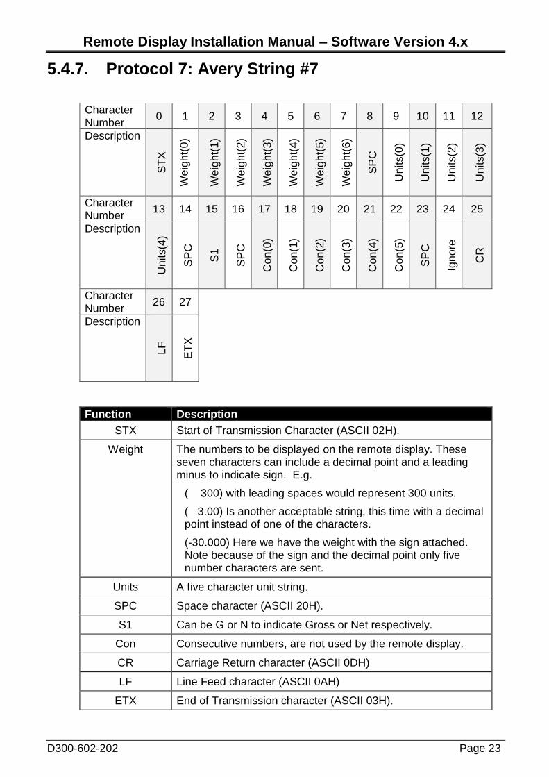
5.4.7. Protocol 7: Avery String #7
Character Number
0 1 2 3 4 5 6 7 8 9 10 11 12
Description
ST
X
We
igh
t(0
)
We
igh
t(1
)
We
igh
t(2
)
We
igh
t(3
)
We
igh
t(4
)
We
igh
t(5
)
We
igh
t(6
)
SP
C
Units(0
)
Units(1
)
Units(2
)
Units(3
)
Character Number
13 14 15 16 17 18 19 20 21 22 23 24 25
Description
Units(4
)
SP
C
S1
SP
C
Con
(0)
Con
(1)
Con
(2)
Con
(3)
Con
(4)
Con
(5)
SP
C
Ign
ore
CR
Character Number
26 27
Description
LF
ET
X
Function Description
STX Start of Transmission Character (ASCII 02H).
Weight The numbers to be displayed on the remote display. These seven characters can include a decimal point and a leading minus to indicate sign. E.g.
( 300) with leading spaces would represent 300 units.
( 3.00) Is another acceptable string, this time with a decimal point instead of one of the characters.
(-30.000) Here we have the weight with the sign attached. Note because of the sign and the decimal point only five number characters are sent.
Units A five character unit string.
SPC Space character (ASCII 20H).
S1 Can be G or N to indicate Gross or Net respectively.
Con Consecutive numbers, are not used by the remote display.
CR Carriage Return character (ASCII 0DH)
LF Line Feed character (ASCII 0AH)
ETX End of Transmission character (ASCII 03H).
Remote Display Installation Manual – Software Version 4.x
Page 24 D300-602-202
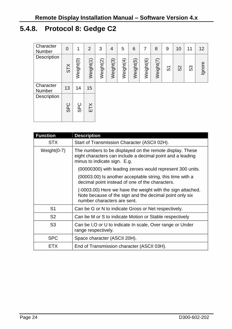
5.4.8. Protocol 8: Gedge C2
Character Number
0 1 2 3 4 5 6 7 8 9 10 11 12
Description
ST
X
We
igh
t(0
)
We
igh
t(1
)
We
igh
t(2
)
We
igh
t(3
)
We
igh
t(4
)
We
igh
t(5
)
We
igh
t(6
)
We
igh
t(7
)
S1
S2
S3
Ign
ore
Character Number
13 14 15
Description
SP
C
SP
C
ET
X
Function Description
STX Start of Transmission Character (ASCII 02H).
Weight(0-7) The numbers to be displayed on the remote display. These eight characters can include a decimal point and a leading minus to indicate sign. E.g.
(00000300) with leading zeroes would represent 300 units.
(00003.00) Is another acceptable string, this time with a decimal point instead of one of the characters.
(-0003.00) Here we have the weight with the sign attached. Note because of the sign and the decimal point only six number characters are sent.
S1 Can be G or N to indicate Gross or Net respectively.
S2 Can be M or S to indicate Motion or Stable respectively
S3 Can be I,O or U to indicate In scale, Over range or Under range respectively.
SPC Space character (ASCII 20H).
ETX End of Transmission character (ASCII 03H).
Remote Display Installation Manual – Software Version 4.x
D300-602-202 Page 25
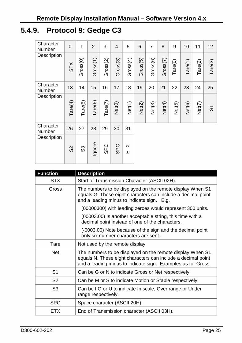
5.4.9. Protocol 9: Gedge C3
Character Number
0 1 2 3 4 5 6 7 8 9 10 11 12
Description
ST
X
Gro
ss(0
)
Gro
ss(1
)
Gro
ss(2
)
Gro
ss(3
)
Gro
ss(4
)
Gro
ss(5
)
Gro
ss(6
)
Gro
ss(7
)
Ta
re(0
)
Ta
re(1
)
Ta
re(2
)
Ta
re(3
)
Character Number
13 14 15 16 17 18 19 20 21 22 23 24 25
Description
Ta
re(4
)
Ta
re(5
)
Ta
re(6
)
Ta
re(7
)
Net(
0)
Net(
1)
Net(
2)
Net(
3)
Net(
4)
Net(
5)
Net(
6)
Net(
7)
S1
Character Number
26 27 28 29 30 31
Description
S2
S3
Ign
ore
SP
C
SP
C
ET
X
Function Description
STX Start of Transmission Character (ASCII 02H).
Gross The numbers to be displayed on the remote display When S1 equals G. These eight characters can include a decimal point and a leading minus to indicate sign. E.g.
(00000300) with leading zeroes would represent 300 units.
(00003.00) Is another acceptable string, this time with a decimal point instead of one of the characters.
(-0003.00) Note because of the sign and the decimal point only six number characters are sent.
Tare Not used by the remote display
Net The numbers to be displayed on the remote display When S1 equals N. These eight characters can include a decimal point and a leading minus to indicate sign. Examples as for Gross.
S1 Can be G or N to indicate Gross or Net respectively.
S2 Can be M or S to indicate Motion or Stable respectively
S3 Can be I,O or U to indicate In scale, Over range or Under range respectively.
SPC Space character (ASCII 20H).
ETX End of Transmission character (ASCII 03H).
Remote Display Installation Manual – Software Version 4.x
Page 26 D300-602-202
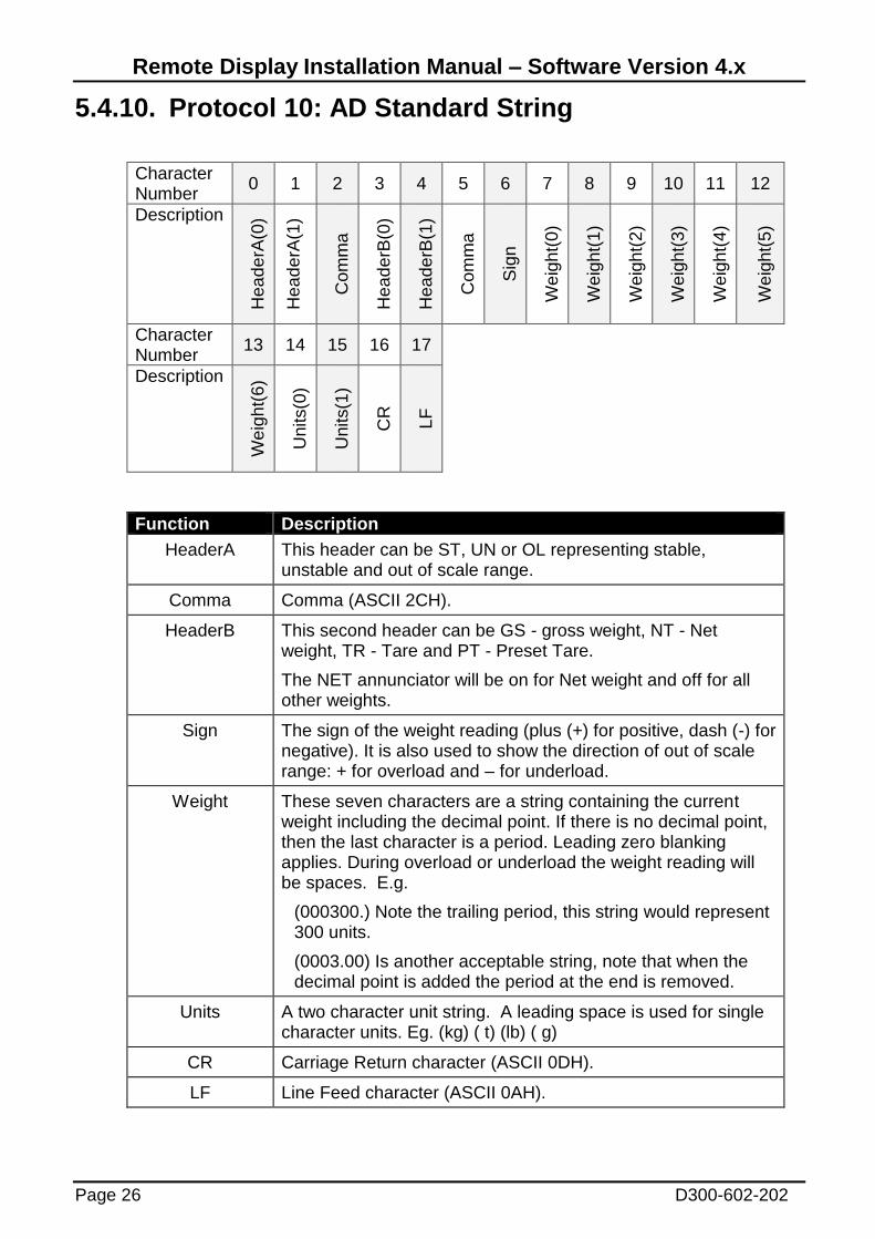
5.4.10. Protocol 10: AD Standard String
Character Number
0 1 2 3 4 5 6 7 8 9 10 11 12
Description
Hea
de
rA(0
)
Hea
de
rA(1
)
Com
ma
Hea
de
rB(0
)
Hea
de
rB(1
)
Com
ma
Sig
n
We
igh
t(0
)
We
igh
t(1
)
We
igh
t(2
)
We
igh
t(3
)
We
igh
t(4
)
We
igh
t(5
)
Character Number
13 14 15 16 17
Description
We
igh
t(6
)
Units(0
)
Units(1
)
CR
LF
Function Description
HeaderA This header can be ST, UN or OL representing stable, unstable and out of scale range.
Comma Comma (ASCII 2CH).
HeaderB This second header can be GS - gross weight, NT - Net weight, TR - Tare and PT - Preset Tare.
The NET annunciator will be on for Net weight and off for all other weights.
Sign The sign of the weight reading (plus (+) for positive, dash (-) for negative). It is also used to show the direction of out of scale range: + for overload and – for underload.
Weight These seven characters are a string containing the current weight including the decimal point. If there is no decimal point, then the last character is a period. Leading zero blanking applies. During overload or underload the weight reading will be spaces. E.g.
(000300.) Note the trailing period, this string would represent 300 units.
(0003.00) Is another acceptable string, note that when the decimal point is added the period at the end is removed.
Units A two character unit string. A leading space is used for single character units. Eg. (kg) ( t) (lb) ( g)
CR Carriage Return character (ASCII 0DH).
LF Line Feed character (ASCII 0AH).
Remote Display Installation Manual – Software Version 4.x
D300-602-202 Page 27
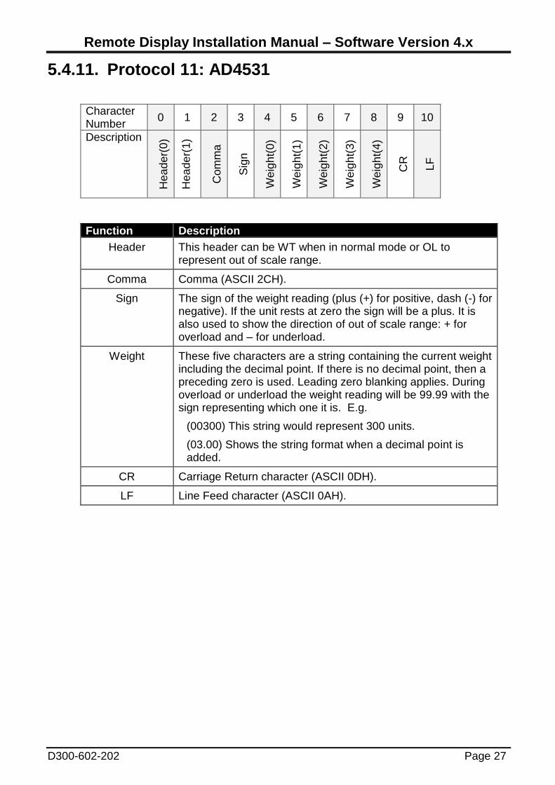
5.4.11. Protocol 11: AD4531
Character Number
0 1 2 3 4 5 6 7 8 9 10
Description
Hea
de
r(0
)
Hea
de
r(1
)
Com
ma
Sig
n
We
igh
t(0
)
We
igh
t(1
)
We
igh
t(2
)
We
igh
t(3
)
We
igh
t(4
)
CR
LF
Function Description
Header This header can be WT when in normal mode or OL to represent out of scale range.
Comma Comma (ASCII 2CH).
Sign The sign of the weight reading (plus (+) for positive, dash (-) for negative). If the unit rests at zero the sign will be a plus. It is also used to show the direction of out of scale range: + for overload and – for underload.
Weight These five characters are a string containing the current weight including the decimal point. If there is no decimal point, then a preceding zero is used. Leading zero blanking applies. During overload or underload the weight reading will be 99.99 with the sign representing which one it is. E.g.
(00300) This string would represent 300 units.
(03.00) Shows the string format when a decimal point is added.
CR Carriage Return character (ASCII 0DH).
LF Line Feed character (ASCII 0AH).

Remote Display Installation Manual – Software Version 4.x
Page 28 D300-602-202
5.4.12. Protocol 12: Toledo Continuous Character Number
0 1 2 3 4 5 6 7 8 9 10 11 12
Description
ST
X
SW
(A)
SW
(B)
SW
(C)
We
igh
t (0
)
We
igh
t (1
)
We
igh
t (2
)
We
igh
t (3
)
We
igh
t (4
)
We
igh
t (5
)
Ta
re(0
)
Ta
re(1
)
Ta
re(2
)
Character Number
13 14 15 16
Description
Ta
re(3
)
Ta
re(4
)
Ta
re(5
)
CR
Function Description
STX Start of Transmission Character (ASCII 02H).
SW SW A, B and C are each a collection of status bits. The relevant bits of the three characters are shown below in tabular
form. All other status bits are ignored.
Weight These six characters are a string containing the current gross or net weight not including the decimal point or a sign.
Tare Not used by the remote display
CR Carriage return character (ASCII 0DH).
SW A Bits 0,1 and 2 SW B Bits 0,1,2,3 and 4
Bits Decimal
Point
Location
Status
Bits
Function
0 1 2
0 0 0 XXXX00 Bit 0 Gross = 0, Net = 1
1 0 0 XXXXX0 Bit 1 Sign, Positive = 0, Negative = 1
0 1 0 XXXXXX Bit 2 Out of Range = 1 (overload or underload)
1 1 0 XXXXX.X Bit 3 Motion = 1
0 0 1 XXXX.XX Bit 4 lb = 0, kg = 1 (see also SW C )
SW C Bits 0,1 and 2
Bits Units
0 1 2
0 0 0 lb or kg, selected by SW B bit 4
1 0 0 grams (g)
0 1 0 tons (t)
Remote Display Installation Manual – Software Version 4.x
D300-602-202 Page 29
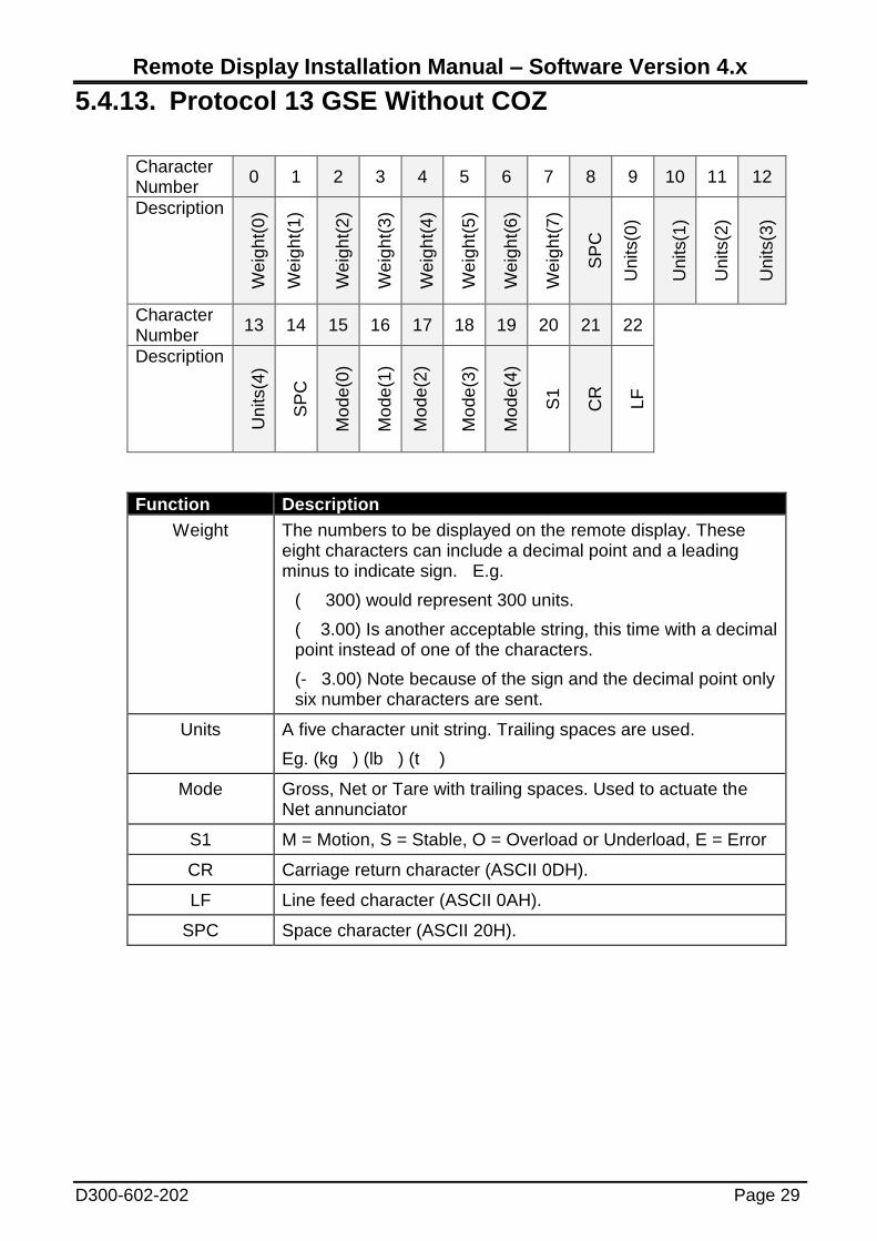
5.4.13. Protocol 13 GSE Without COZ
Character Number
0 1 2 3 4 5 6 7 8 9 10 11 12
Description
We
igh
t(0
)
We
igh
t(1
)
We
igh
t(2
)
We
igh
t(3
)
We
igh
t(4
)
We
igh
t(5
)
We
igh
t(6
)
We
igh
t(7
)
SP
C
Units(0
)
Units(1
)
Units(2
)
Units(3
)
Character Number
13 14 15 16 17 18 19 20 21 22
Description
Units(4
)
SP
C
Mo
de
(0)
Mo
de
(1)
Mo
de
(2)
Mo
de
(3)
Mo
de
(4)
S1
CR
LF
Function Description
Weight The numbers to be displayed on the remote display. These eight characters can include a decimal point and a leading minus to indicate sign. E.g.
( 300) would represent 300 units.
( 3.00) Is another acceptable string, this time with a decimal point instead of one of the characters.
(- 3.00) Note because of the sign and the decimal point only six number characters are sent.
Units A five character unit string. Trailing spaces are used.
Eg. (kg ) (lb ) (t )
Mode Gross, Net or Tare with trailing spaces. Used to actuate the Net annunciator
S1 M = Motion, S = Stable, O = Overload or Underload, E = Error
CR Carriage return character (ASCII 0DH).
LF Line feed character (ASCII 0AH).
SPC Space character (ASCII 20H).
Remote Display Installation Manual – Software Version 4.x
Page 30 D300-602-202
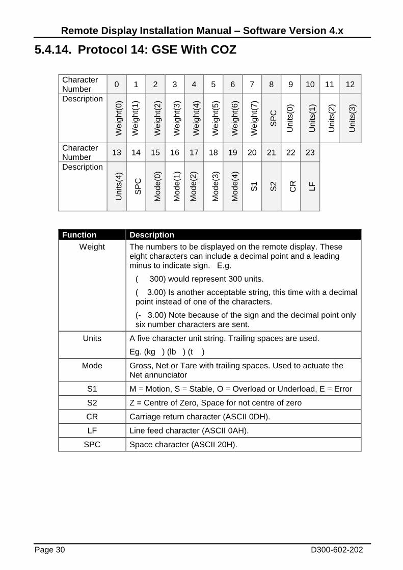
5.4.14. Protocol 14: GSE With COZ
Character Number
0 1 2 3 4 5 6 7 8 9 10 11 12
Description
We
igh
t(0
)
We
igh
t(1
)
We
igh
t(2
)
We
igh
t(3
)
We
igh
t(4
)
We
igh
t(5
)
We
igh
t(6
)
We
igh
t(7
)
SP
C
Units(0
)
Units(1
)
Units(2
)
Units(3
)
Character Number
13 14 15 16 17 18 19 20 21 22 23
Description
Units(4
)
SP
C
Mo
de
(0)
Mo
de
(1)
Mo
de
(2)
Mo
de
(3)
Mo
de
(4)
S1
S2
CR
LF
Function Description
Weight The numbers to be displayed on the remote display. These eight characters can include a decimal point and a leading minus to indicate sign. E.g.
( 300) would represent 300 units.
( 3.00) Is another acceptable string, this time with a decimal point instead of one of the characters.
(- 3.00) Note because of the sign and the decimal point only six number characters are sent.
Units A five character unit string. Trailing spaces are used.
Eg. (kg ) (lb ) (t )
Mode Gross, Net or Tare with trailing spaces. Used to actuate the Net annunciator
S1 M = Motion, S = Stable, O = Overload or Underload, E = Error
S2 Z = Centre of Zero, Space for not centre of zero
CR Carriage return character (ASCII 0DH).
LF Line feed character (ASCII 0AH).
SPC Space character (ASCII 20H).

Remote Display Installation Manual – Software Version 4.x
D300-602-202 Page 31
5.4.15. Protocol 15: Schenk Without DP
Character Number
0 1 2 3 4 5 6 7 8 9 10 11 12
Description
ST
X
Ign
ore
Ign
ore
Ign
ore
Sig
n
Net(
0)
Net(
1)
Net(
2)
Net(
3)
Net(
4)
Ta
re(0
)
Ta
re(1
)
Ta
re(2
)
Character Number
13 14 15 16 17 18 19 20 21 22 23
Description
Ta
re(3
)
Ta
re(4
)
Ta
re(5
)
Ta
re(6
)
Ta
re(7
)
Ta
re(8
)
SP
C
S1
S2
LF
CR
Function Description
STX Start of Transmission Character (ASCII 02H).
Sign Represents the sign of the weight reading (space for positive, dash (-) for negative.
Net The numbers to be displayed on the remote display. E.g.
( 300) would represent 300 units.
Tare Not used by the remote display.
SPC Space character (ASCII 20H).
S1 ASCII character (0-F) with values as shown in the table below
S2 ASCII character (0-F) with values as shown in the table below
LF Line feed character (ASCII 0AH).
CR Carriage return character (ASCII 0DH).
S1 Bit S1 Status S2 Value S2 Status
0 Tare=0, preset Tare=1
Only used in Net mode.
0 Units = kg
1 Motion = 0, Stable=1 1 Units = g
2 Not COZ=0, COZ=1 3 Units = T
3 Gross=0, Net=1 5 Weight longer than string,
Display will be blanked.

Remote Display Installation Manual – Software Version 4.x
Page 32 D300-602-202
5.4.16. Protocol 16: Schenk With DP
Character Number
0 1 2 3 4 5 6 7 8 9 10 11 12
Description
ST
X
Ign
ore
Ign
ore
Ign
ore
Sig
n
Net(
0)
Net(
1)
Net(
2)
Net(
3)
Net(
4)
Net(
5)
Ta
re(0
)
Ta
re(1
)
Character Number
13 14 15 16 17 18 19 20 21 22 23 24 25
Description
Ta
re(2
)
Ta
re(3
)
Ta
re(4
)
Ta
re(5
)
Ta
re(6
)
Ta
re(7
)
Ta
re(8
)
Ta
re(9
)
SP
C
S1
S2
LF
CR
Function Description
STX Start of Transmission Character (ASCII 02H).
Sign Represents the sign of the weight reading (space for positive, dash (-) for negative.
Net The numbers to be displayed on the remote display. These six characters include a decimal. E.g.
( 300.0) with leading spaces would represent 300 units.
Tare Not used by the remote display.
SPC Space character (ASCII 20H).
S1 ASCII character (0-F) with values as shown in the table below
S2 ASCII character (0-F) with values as shown in the table below
LF Line feed character (ASCII 0AH).
CR Carriage return character (ASCII 0DH).
S1 Bit S1 Status S2 Value S2 Status
0 Tare=0, preset Tare=1
Only used in Net mode.
0 Units = kg
1 Motion = 0, Stable=1 1 Units = g
2 Not COZ=0, COZ=1 3 Units = T
3 Gross=0, Net=1 5 Weight longer than string,
Display will be blanked.
Remote Display Installation Manual – Software Version 4.x
D300-602-202 Page 33
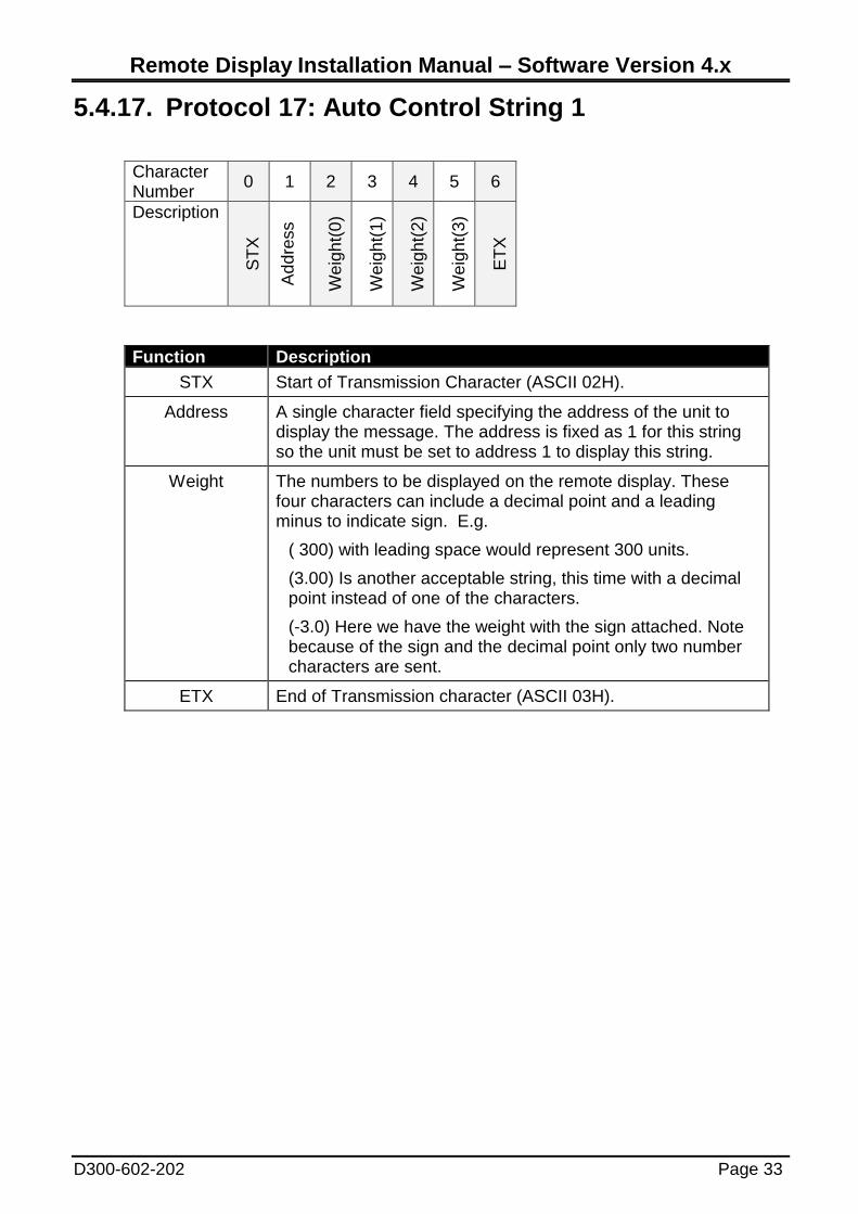
5.4.17. Protocol 17: Auto Control String 1
Character Number
0 1 2 3 4 5 6
Description
ST
X
Ad
dre
ss
We
igh
t(0)
We
igh
t(1)
We
igh
t(2)
We
igh
t(3)
ET
X
Function Description
STX Start of Transmission Character (ASCII 02H).
Address A single character field specifying the address of the unit to display the message. The address is fixed as 1 for this string so the unit must be set to address 1 to display this string.
Weight The numbers to be displayed on the remote display. These four characters can include a decimal point and a leading minus to indicate sign. E.g.
( 300) with leading space would represent 300 units.
(3.00) Is another acceptable string, this time with a decimal point instead of one of the characters.
(-3.0) Here we have the weight with the sign attached. Note because of the sign and the decimal point only two number characters are sent.
ETX End of Transmission character (ASCII 03H).

Remote Display Installation Manual – Software Version 4.x
Page 34 D300-602-202
5.4.18. Protocol 18: Auto Control String 2
Character Number
0 1 2 3 4 5 6 7 8 9 10
Description
ST
X
Ad
dre
ss
Te
xt(
0)
Te
xt(
1)
Te
xt(
2)
Te
xt(
3)
Te
xt(
4)
Te
xt(
5)
Te
xt(
6)
Te
xt(
7)
EN
Q
Function Description
STX Start of Transmission Character (ASCII 02H).
Address A single character field specifying the address of the unit to display the message. The address is fixed as 2 for this string so the unit must be set to address 2 to display this string.
Text These eight (8) characters will be displayed. They may be ASCII characters instead of numbers in which case the display will show text. These eight characters can include a decimal point and a leading minus to indicate sign. Example:
( 300) would represent 300 units.
( - 3.00) a decimal point and minus sign can be used.
( CEMENT) text can be sent.
ENQ Used as end of transmission character (ASCII 05H).
Remote Display Installation Manual – Software Version 4.x
D300-602-202 Page 35
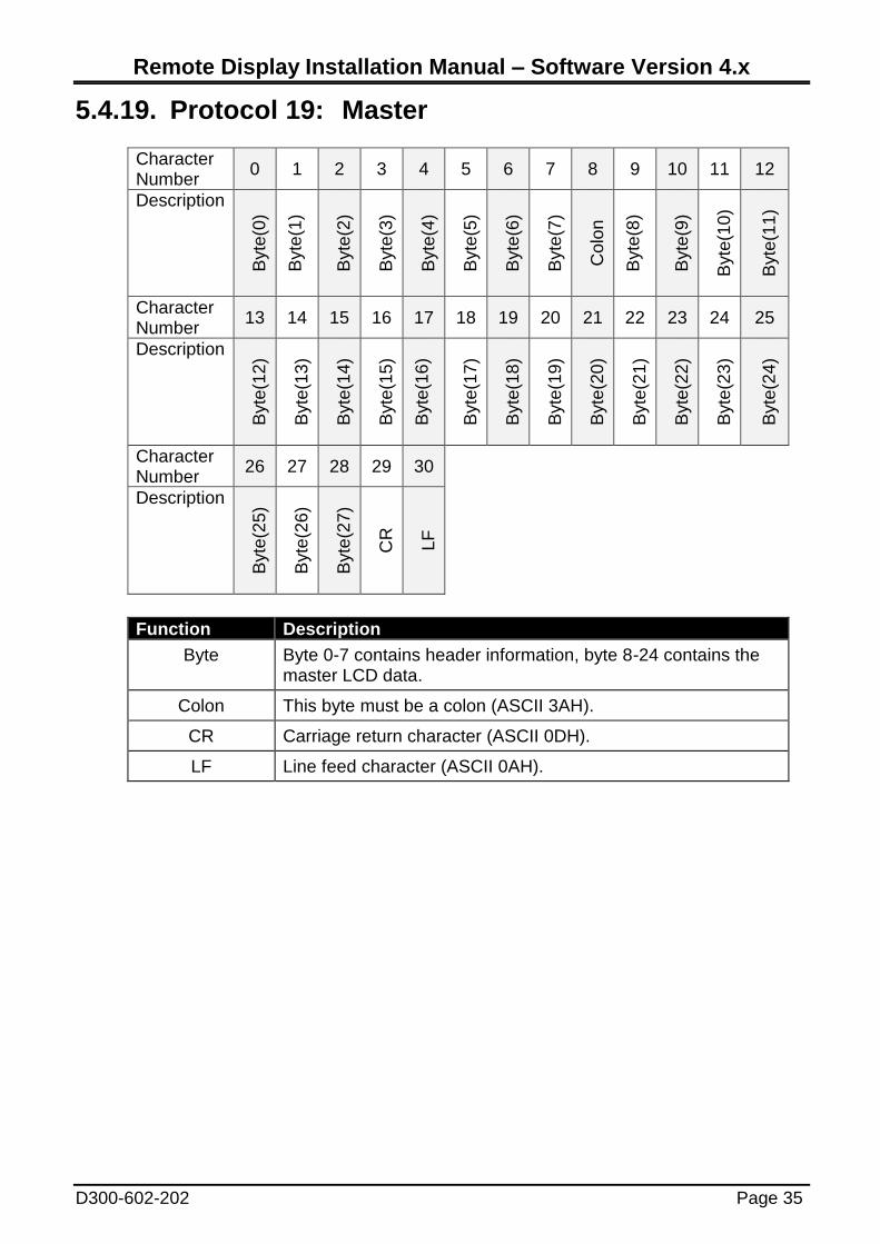
5.4.19. Protocol 19: Master
Character Number
0 1 2 3 4 5 6 7 8 9 10 11 12
Description
Byte
(0)
Byte
(1)
Byte
(2)
Byte
(3)
Byte
(4)
Byte
(5)
Byte
(6)
Byte
(7)
Colo
n
Byte
(8)
Byte
(9)
Byte
(10
)
Byte
(11
)
Character Number
13 14 15 16 17 18 19 20 21 22 23 24 25
Description
Byte
(12
)
Byte
(13
)
Byte
(14
)
Byte
(15
)
Byte
(16
)
Byte
(17
)
Byte
(18
)
Byte
(19
)
Byte
(20
)
Byte
(21
)
Byte
(22
)
Byte
(23
)
Byte
(24
)
Character Number
26 27 28 29 30
Description
Byte
(25
)
Byte
(26
)
Byte
(27
)
CR
LF
Function Description
Byte Byte 0-7 contains header information, byte 8-24 contains the master LCD data.
Colon This byte must be a colon (ASCII 3AH).
CR Carriage return character (ASCII 0DH).
LF Line feed character (ASCII 0AH).
Remote Display Installation Manual – Software Version 4.x
Page 36 D300-602-202
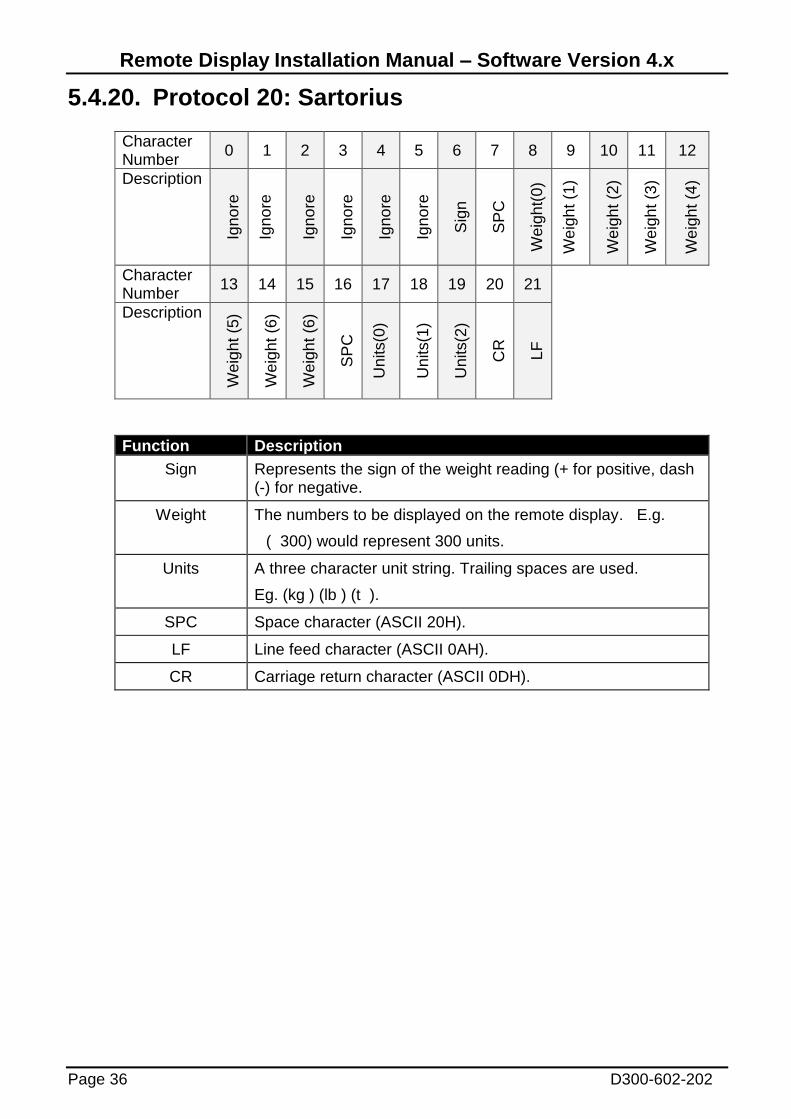
5.4.20. Protocol 20: Sartorius
Character Number
0 1 2 3 4 5 6 7 8 9 10 11 12
Description
Ign
ore
Ign
ore
Ign
ore
Ign
ore
Ign
ore
Ign
ore
Sig
n
SP
C
We
igh
t(0
)
We
igh
t (1
)
We
igh
t (2
)
We
igh
t (3
)
We
igh
t (4
)
Character Number
13 14 15 16 17 18 19 20 21
Description
We
igh
t (5
)
We
igh
t (6
)
We
igh
t (6
)
SP
C
Units(0
)
Units(1
)
Units(2
)
CR
LF
Function Description
Sign Represents the sign of the weight reading (+ for positive, dash (-) for negative.
Weight The numbers to be displayed on the remote display. E.g.
( 300) would represent 300 units.
Units A three character unit string. Trailing spaces are used.
Eg. (kg ) (lb ) (t ).
SPC Space character (ASCII 20H).
LF Line feed character (ASCII 0AH).
CR Carriage return character (ASCII 0DH).
Remote Display Installation Manual – Software Version 4.x
D300-602-202 Page 37
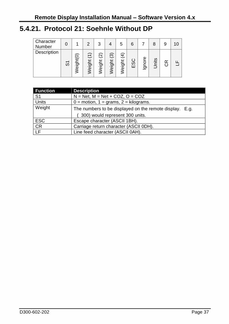
5.4.21. Protocol 21: Soehnle Without DP
Character Number
0 1 2 3 4 5 6 7 8 9 10
Description
S1
We
igh
t(0
)
We
igh
t (1
)
We
igh
t (2
)
We
igh
t (3
)
We
igh
t (4
)
ES
C
Ign
ore
Units
CR
LF
Function Description
S1 N = Net, M = Net + COZ, O = COZ
Units 0 = motion, 1 = grams, 2 = kilograms.
Weight The numbers to be displayed on the remote display. E.g.
( 300) would represent 300 units.
ESC Escape character (ASCII 1BH).
CR Carriage return character (ASCII 0DH).
LF Line feed character (ASCII 0AH).
Remote Display Installation Manual – Software Version 4.x
Page 38 D300-602-202
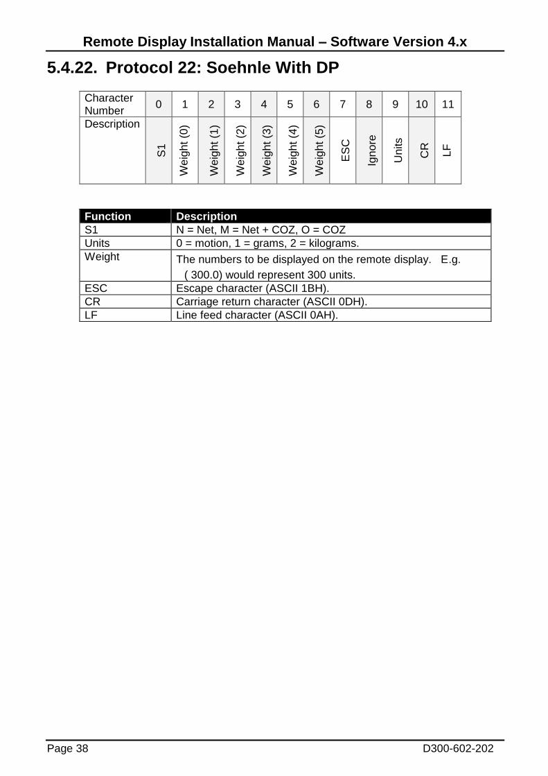
5.4.22. Protocol 22: Soehnle With DP
Character Number
0 1 2 3 4 5 6 7 8 9 10 11
Description
S1
We
igh
t (0
)
We
igh
t (1
)
We
igh
t (2
)
We
igh
t (3
)
We
igh
t (4
)
We
igh
t (5
)
ES
C
Ign
ore
Units
CR
LF
Function Description
S1 N = Net, M = Net + COZ, O = COZ
Units 0 = motion, 1 = grams, 2 = kilograms.
Weight The numbers to be displayed on the remote display. E.g.
( 300.0) would represent 300 units.
ESC Escape character (ASCII 1BH).
CR Carriage return character (ASCII 0DH).
LF Line feed character (ASCII 0AH).
Remote Display Installation Manual – Software Version 4.x
D300-602-202 Page 39
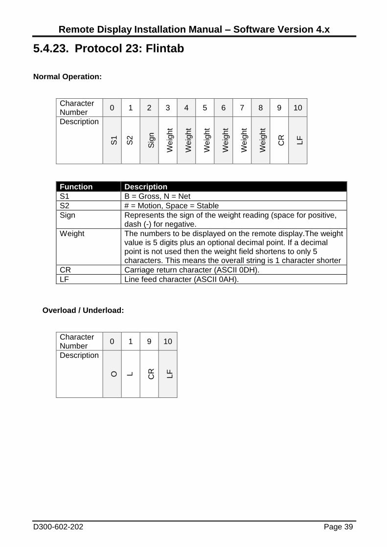
5.4.23. Protocol 23: Flintab
Normal Operation:
Character Number
0 1 2 3 4 5 6 7 8 9 10
Description S
1
S2
Sig
n
We
igh
t
We
igh
t
We
igh
t
We
igh
t
We
igh
t
We
igh
t
CR
LF
Function Description
S1 B = Gross, N = Net
S2 # = Motion, Space = Stable
Sign Represents the sign of the weight reading (space for positive, dash (-) for negative.
Weight The numbers to be displayed on the remote display.The weight value is 5 digits plus an optional decimal point. If a decimal point is not used then the weight field shortens to only 5 characters. This means the overall string is 1 character shorter
CR Carriage return character (ASCII 0DH).
LF Line feed character (ASCII 0AH).
Overload / Underload:
Character Number
0 1 9 10
Description
O
L
CR
LF
Remote Display Installation Manual – Software Version 4.x
Page 40 D300-602-202
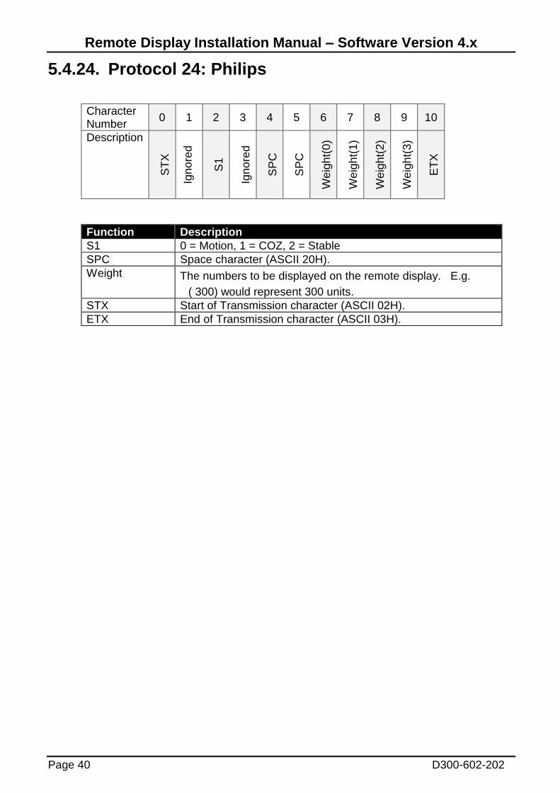
5.4.24. Protocol 24: Philips
Character Number
0 1 2 3 4 5 6 7 8 9 10
Description
ST
X
Ign
ore
d
S1
Ign
ore
d
SP
C
SP
C
We
igh
t(0
)
We
igh
t(1
)
We
igh
t(2
)
We
igh
t(3
)
ET
X
Function Description
S1 0 = Motion, 1 = COZ, 2 = Stable
SPC Space character (ASCII 20H).
Weight The numbers to be displayed on the remote display. E.g.
( 300) would represent 300 units.
STX Start of Transmission character (ASCII 02H).
ETX End of Transmission character (ASCII 03H).

Remote Display Installation Manual – Software Version 4.x
D300-602-202 Page 41
5.4.25. Protocol 25: Condec
Character Number
0 1 2 3 4 5 6 7 8 9 10 11 12 13
Description
ST
X
Sig
n
We
igh
t(0
)
We
igh
t(1
)
We
igh
t(2
)
We
igh
t(3
)
We
igh
t(4
)
We
igh
t(5
)
We
igh
t(6
)
Units
S1
S2
CR
LF
Function Description
STX Start of Transmission Character (ASCII 02H).
Sign Represents the sign of the weight reading (space for positive, dash (-) for negative.
Weight(0-6) These seven characters are a string containing the current weight including the decimal point. If there is no decimal point, then the first character is a space. Leading zero suppression is applied.
Examples:
( 300) will display as “300”
(0030.00 will display as “30.00”
Units L = Lb, K = kg
S1 G = Gross, N = Net
S2 Space = OK, M = Motion, O = Overload/Underload
CR Carriage return character (ASCII 0DH).
LF Line feed character (ASCII 0AH).
Remote Display Installation Manual – Software Version 4.x
Page 42 D300-602-202
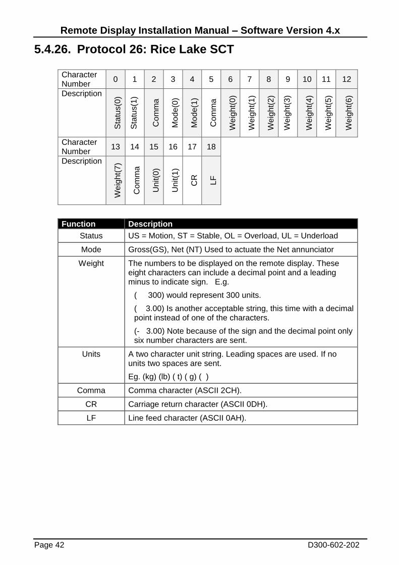
5.4.26. Protocol 26: Rice Lake SCT
Character Number
0 1 2 3 4 5 6 7 8 9 10 11 12
Description
Sta
tus(0
)
Sta
tus(1
)
Com
ma
Mo
de
(0)
Mo
de
(1)
Com
ma
We
igh
t(0
)
We
igh
t(1
)
We
igh
t(2
)
We
igh
t(3
)
We
igh
t(4
)
We
igh
t(5
)
We
igh
t(6
)
Character Number
13 14 15 16 17 18
Description
We
igh
t(7
)
Com
ma
Unit(0
)
Unit(1
)
CR
LF
Function Description
Status US = Motion, ST = Stable, OL = Overload, UL = Underload
Mode Gross(GS), Net (NT) Used to actuate the Net annunciator
Weight The numbers to be displayed on the remote display. These eight characters can include a decimal point and a leading minus to indicate sign. E.g.
( 300) would represent 300 units.
( 3.00) Is another acceptable string, this time with a decimal point instead of one of the characters.
(- 3.00) Note because of the sign and the decimal point only six number characters are sent.
Units A two character unit string. Leading spaces are used. If no units two spaces are sent.
Eg. (kg) (lb) ( t) ( g) ( )
Comma Comma character (ASCII 2CH).
CR Carriage return character (ASCII 0DH).
LF Line feed character (ASCII 0AH).

Remote Display Installation Manual – Software Version 4.x
D300-602-202 Page 43
5.4.27. Protocol 27: Systec
Character Number
0 1 2 3 4 5 6 7 8 9 10 11 12
Description
Sta
tus(0
)
Sta
tus(1
)
We
igh
t(0
)
We
igh
t(1
)
We
igh
t(2
)
We
igh
t(3
)
We
igh
t(4
)
We
igh
t(5
)
We
igh
t(6
)
We
igh
t(7
)
We
igh
t(8
)
We
igh
t(9
)
SP
C
Character Number
13 14 15 16
Description
Unit(0
)
Unit(1
)
CR
LF
Function Description
Status SD = Motion, S_ = Stable
Weight The numbers to be displayed on the remote display. These eight characters can include a decimal point and a leading minus to indicate sign. E.g.
( 300) would represent 300 units.
( 3.00) Is another acceptable string, this time with a decimal point instead of one of the characters.
(- 3.00) Note because of the sign and the decimal point only six number characters are sent.
SPC Space character (ASCII 20H)
Units A two character unit string. Leading spaces are used. If no units two spaces are sent.
Eg. (kg) (lb) (t ) (g ) ( )
CR Carriage return character (ASCII 0DH).
LF Line feed character (ASCII 0AH).
Remote Display Installation Manual – Software Version 4.x
Page 44 D300-602-202
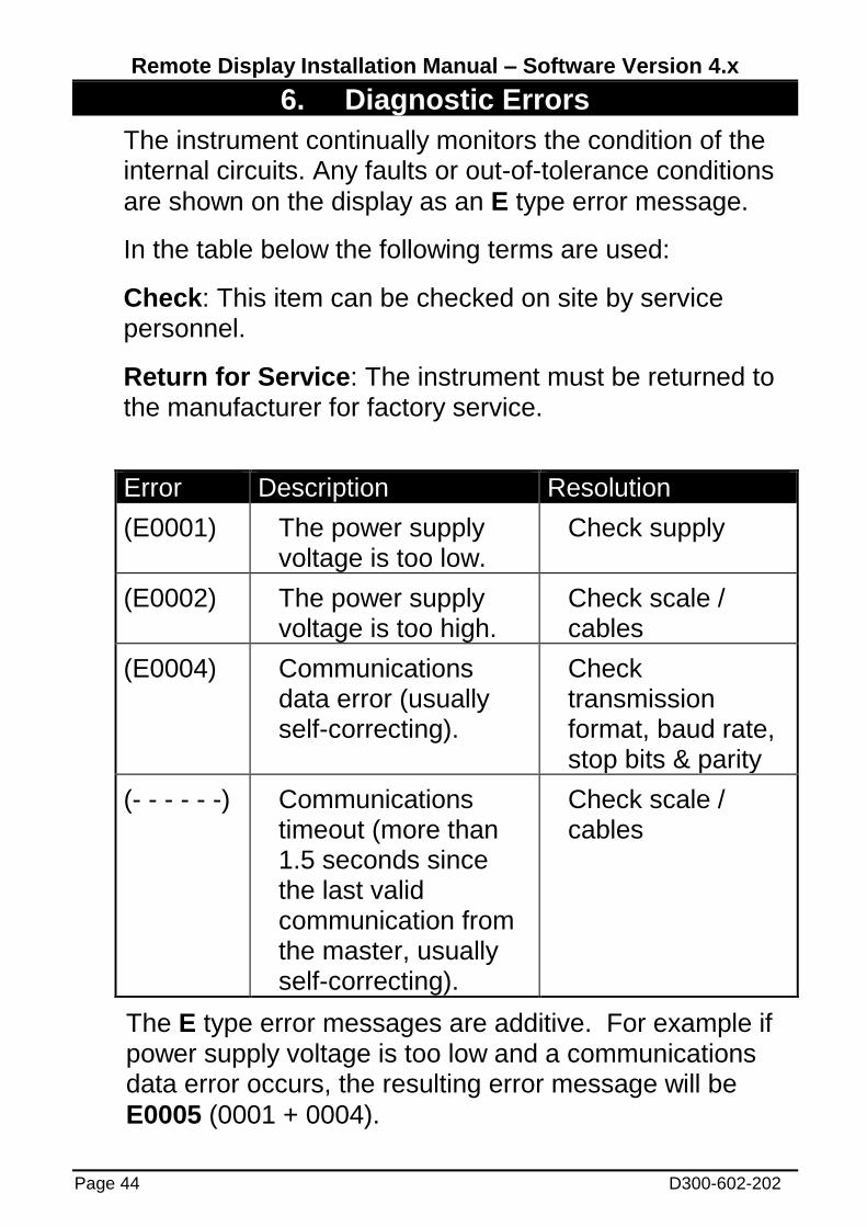
6. Diagnostic Errors
The instrument continually monitors the condition of the internal circuits. Any faults or out-of-tolerance conditions
are shown on the display as an E type error message.
In the table below the following terms are used:
Check: This item can be checked on site by service personnel.
Return for Service: The instrument must be returned to the manufacturer for factory service.
Error Description Resolution
(E0001) The power supply voltage is too low.
Check supply
(E0002) The power supply voltage is too high.
Check scale / cables
(E0004) Communications data error (usually self-correcting).
Check transmission format, baud rate, stop bits & parity
(- - - - - -) Communications timeout (more than 1.5 seconds since the last valid communication from the master, usually self-correcting).
Check scale / cables
The E type error messages are additive. For example if power supply voltage is too low and a communications data error occurs, the resulting error message will be
E0005 (0001 + 0004).

Remote Display Installation Manual – Software Version 4.x
D300-602-202 Page 45
Notes:

Remote Display Installation Manual – Software Version 4.x
Page 46 D300-602-202
Notes:
Remote Display Installation Manual – Software Version 4.x
D300-602-202 Page 47
Notes:
Remote Display Installation Manual – Software Version 4.x
Page 48 D300-602-202