Embed Size (px)
Citation preview
74-06176-000-B 9/95 © 1995 Radionics
R A D I O N I C S
D5200 Programmer
Operation Manual
A-5200-030-000
D5200 Programmer Operation ManualPage 1 © 1991-1995 Radionics74-06176-000-B 9/95
A-5200-030-00
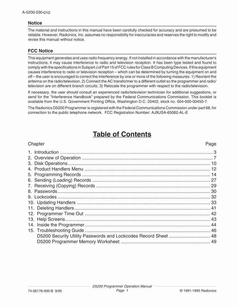
NoticeThe material and instructions in this manual have been carefully checked for accuracy and are presumed to bereliable. However, Radionics, Inc. assumes no responsibility for inaccuracies and reserves the right to modify andrevise this manual without notice.
FCC NoticeThis equipment generates and uses radio frequency energy. If not installed in accordance with the manufacturer'sinstructions, it may cause interference to radio and television reception. It has been type tested and found tocomply with the specifications in Subpart J of Part 15 of FCC rules for Class B Computing Devices. If this equipmentcauses interference to radio or television reception – which can be determined by turning the equipment on andoff – the user is encouraged to correct the interference by one or more of the following measures: 1) Reorient theantenna on the radio/television, 2) Connect the AC transformer to a different outlet so the programmer and radio/television are on different branch circuits, 3) Relocate the programmer with respect to the radio/television.
If necessary, the user should consult an experienced radio/television technician for additional suggestions, orsend for the "Interference Handbook" prepared by the Federal Communications Commission. This booklet isavailable from the U.S. Government Printing Office, Washington D.C. 20402, stock no. 004-000-00450-7.
The Radionics D5200 Programmer is registered with the Federal Communications Commission under part 68, forconnection to the public telephone network. FCC Registration Number: AJ9USA-65062-AL-E
Table of ContentsChapter Page
1. Introduction ...................................................................................................................... 32. Overview of Operation ..................................................................................................... 73. Disk Operations.............................................................................................................. 104. Product Handlers Menu ................................................................................................. 125. Programming Records ................................................................................................... 146. Sending (Loading) Records ........................................................................................... 277. Receiving (Copying) Records ........................................................................................ 298. Passwords...................................................................................................................... 309. Lockcodes ...................................................................................................................... 3210. Updating Handlers ....................................................................................................... 3311. Deleting Handlers......................................................................................................... 4112. Programmer Time Out ................................................................................................. 4213. Help Screens................................................................................................................ 4314. Inside the Programmer................................................................................................. 4415. Troubleshooting Guide ................................................................................................. 46 D5200 Security Utility Passwords and Lockcodes Record Sheet ................................ 48 D5200 Programmer Memory Worksheet ..................................................................... 49
010
D5200 Programmer Operation ManualPage 2 © 1991-1995 Radionics74-06176-000-B 9/95
A-5200-030-20
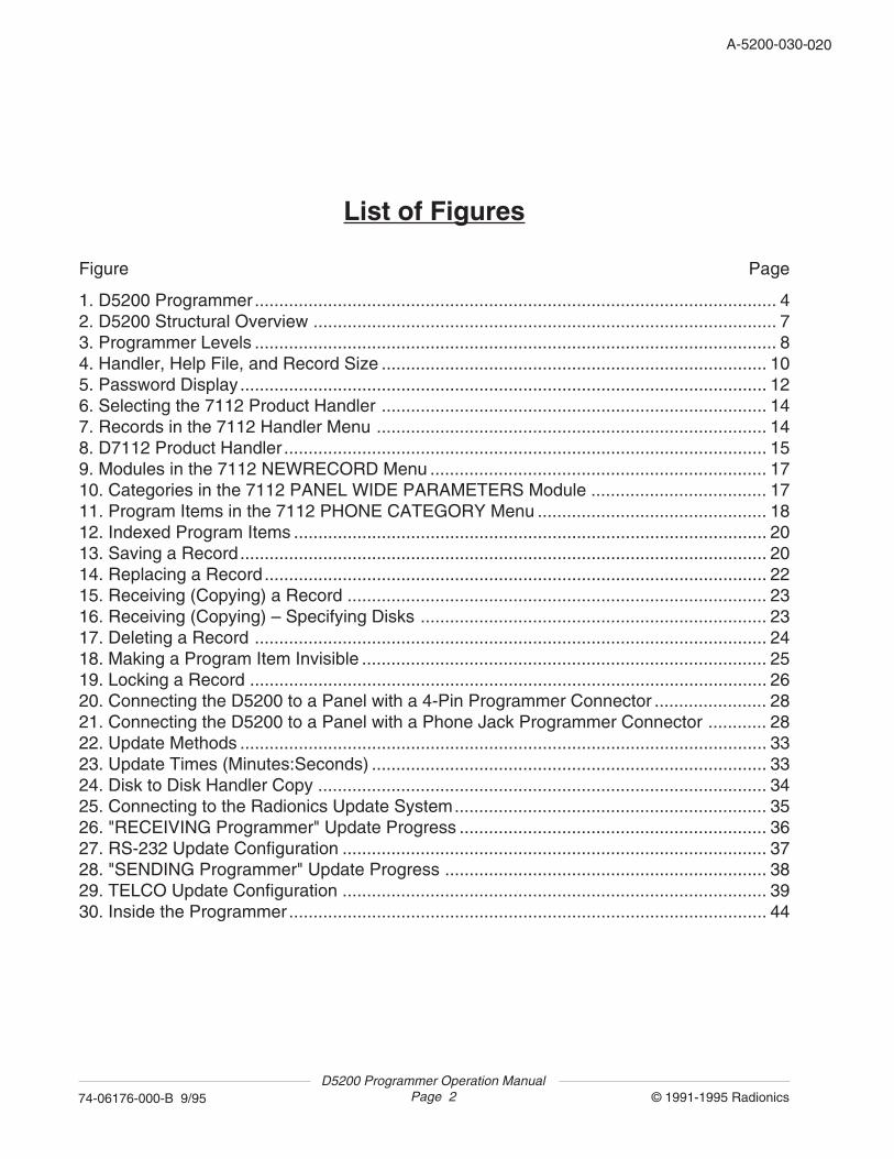
List of Figures
Figure Page
1. D5200 Programmer........................................................................................................... 42. D5200 Structural Overview ............................................................................................... 73. Programmer Levels ........................................................................................................... 84. Handler, Help File, and Record Size ............................................................................... 105. Password Display............................................................................................................ 126. Selecting the 7112 Product Handler ............................................................................... 147. Records in the 7112 Handler Menu ................................................................................ 148. D7112 Product Handler ................................................................................................... 159. Modules in the 7112 NEWRECORD Menu ..................................................................... 1710. Categories in the 7112 PANEL WIDE PARAMETERS Module .................................... 1711. Program Items in the 7112 PHONE CATEGORY Menu ............................................... 1812. Indexed Program Items ................................................................................................. 2013. Saving a Record............................................................................................................ 2014. Replacing a Record....................................................................................................... 2215. Receiving (Copying) a Record ...................................................................................... 2316. Receiving (Copying) – Specifying Disks ....................................................................... 2317. Deleting a Record ......................................................................................................... 2418. Making a Program Item Invisible ................................................................................... 2519. Locking a Record .......................................................................................................... 2620. Connecting the D5200 to a Panel with a 4-Pin Programmer Connector ....................... 2821. Connecting the D5200 to a Panel with a Phone Jack Programmer Connector ............ 2822. Update Methods ............................................................................................................ 3323. Update Times (Minutes:Seconds) ................................................................................. 3324. Disk to Disk Handler Copy ............................................................................................ 3425. Connecting to the Radionics Update System................................................................ 3526. "RECEIVING Programmer" Update Progress ............................................................... 3627. RS-232 Update Configuration ....................................................................................... 3728. "SENDING Programmer" Update Progress .................................................................. 3829. TELCO Update Configuration ....................................................................................... 3930. Inside the Programmer.................................................................................................. 44
020

D5200 Programmer Operation ManualPage 3 © 1991-1995 Radionics74-06176-000-B 9/95
A-5200-030-20
1. Introduction
The D5200 Programmer is a state of the art rugged, compact tool for programming theadvanced line of Radionics security products. The D5200 features include a four-line LCDdisplay, compact keyboard, and expandable memory.
Features• LCD Display
The four-line LCD display is used to provide product handler programming information,help screens for prompts and program items, and status information.
• Keyboard
The programmer keyboard features standard letter layout, function keys for sending(loading) and receiving (copying) records, and "navigation" keys to assist the user inmoving through product handler levels. A Help key provides immediate access toprogramming assistance.
• Removable Data Storage
A connector for a state of the art removable RAM card (32 kbytes to 1 Mbyte) is providedin the D5200. RAM cards with different programmed records can easily be interchanged.See Removable RAM Card in the Specifications section for available sizes. The D5200Programmer is shipped with an internal 128 kbyte RAM disk for product handler andrecord storage.
• Customize Product Handlers
Product handler records can be customized using the VisMode feature. Designate asinvisible selected program items, categories – even entire modules.
• Password Protection
Protect your data by limiting access to programmer functions. Eight passwords withspecific function access authority can be programmed.
• Easy to Update
Conveniently update your programmer - add new handlers and help files – over thephone lines. Transfer handlers and records between D5200 programmers quickly andeasily via the built-in RS-232 serial interface.
• Help Screens
Built-in help messages provide guidance for D5200 operation and product handlerprogramming.
• Power Saving Timeout
Automatic timeout feature safely powers down the D5200 after a programmed amountof time.
030
D5200 Programmer Operation ManualPage 4 © 1991-1995 Radionics74-06176-000-B 9/95
A-5200-030-40
ON HELP CANCEL
RECV(COPY)
SEND(LOAD) CLEAR
EXITGROUP
ENTERGROUP
➞
!1
@2
#3
$4
%5
:6
&7
*8
(9
)0
BACKSPACE
CAPLOCK
=+
_-SHIFT SPACE
<,
>.
?/
Q W E R T Y U I O
A S D F G H J K
MNBVCXZ
EXTERNALPOWER
5200to
5200
RS-232>Aor
RS-232>B
A>RS-232or
B>RS-232
COMMUNICATOR TO / FROMPHONE
TELCO>Aor
TELCO>BRADX UPDATE
A>TELCOor
B>TELCO
ENTER
SHIFT
P
➞
➞
➞
L
AUXILIARY
D5200
--D5200-PROGRAMMER------Radionics-Inc-------Rev--[##.##]----Password:-❏---------
RECEIVINGPROGRAMMER
SENDINGPROGRAMMER
+ -POSITIVE TIP POLARITY
FUNCTION KEYS NAVIGATIONALKEYS
LCD DISPLAY
KEYBOARD
AC ADAPTER PORT
AUXILIARYPORT
RS-232PORT
TELCOPORT
CONTROL/COMMUNICATOR
PORT
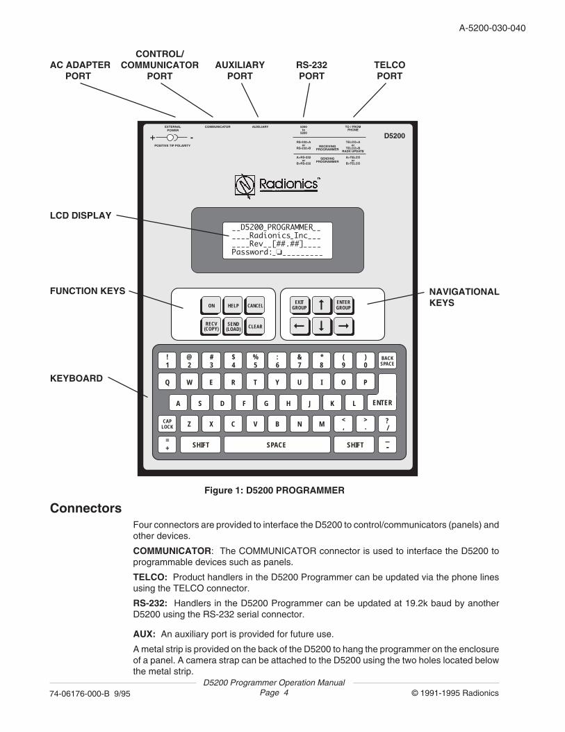
Figure 1: D5200 PROGRAMMER
ConnectorsFour connectors are provided to interface the D5200 to control/communicators (panels) andother devices.
COMMUNICATOR: The COMMUNICATOR connector is used to interface the D5200 toprogrammable devices such as panels.
TELCO: Product handlers in the D5200 Programmer can be updated via the phone linesusing the TELCO connector.
RS-232: Handlers in the D5200 Programmer can be updated at 19.2k baud by anotherD5200 using the RS-232 serial connector.
AUX: An auxiliary port is provided for future use.
A metal strip is provided on the back of the D5200 to hang the programmer on the enclosureof a panel. A camera strap can be attached to the D5200 using the two holes located belowthe metal strip.
040
D5200 Programmer Operation ManualPage 5 © 1991-1995 Radionics74-06176-000-B 9/95
A-5200-030-40
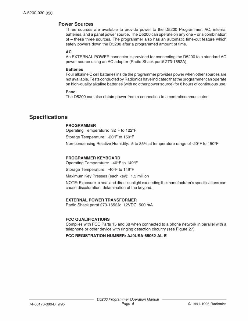
Power SourcesThree sources are available to provide power to the D5200 Programmer: AC, internalbatteries, and a panel power source. The D5200 can operate on any one – or a combinationof – these three sources. The programmer also has an automatic time-out feature whichsafely powers down the D5200 after a programmed amount of time.
ACAn EXTERNAL POWER connector is provided for connecting the D5200 to a standard ACpower source using an AC adapter (Radio Shack part# 273-1652A).
BatteriesFour alkaline C cell batteries inside the programmer provides power when other sources arenot available. Tests conducted by Radionics have indicated that the programmer can operateon high-quality alkaline batteries (with no other power source) for 8 hours of continuous use.
PanelThe D5200 can also obtain power from a connection to a control/communicator.
SpecificationsPROGRAMMEROperating Temperature: 32°F to 122°F
Storage Temperature: -20°F to 150°F
Non-condensing Relative Humidity: 5 to 85% at temperature range of -20°F to 150°F
PROGRAMMER KEYBOARDOperating Temperature: -40°F to 149°F
Storage Temperature: -40°F to 149°F
Maximum Key Presses (each key): 1.5 million
NOTE: Exposure to heat and direct sunlight exceeding the manufacturer's specifications cancause discoloration, delamination of the keypad.
EXTERNAL POWER TRANSFORMERRadio Shack part# 273-1652A: 12VDC, 500 mA
FCC QUALIFICATIONSComplies with FCC Parts 15 and 68 when connected to a phone network in parallel with atelephone or other device with ringing detection circuitry (see Figure 27).
FCC REGISTRATION NUMBER: AJ9USA-65062-AL-E
050
D5200 Programmer Operation ManualPage 6 © 1991-1995 Radionics74-06176-000-B 9/95
A-5200-030-60
Removable RAM Card
Call Radionics Customer ServiceFor Removable RAM Card Information
Refer to Technogram 73-07504-000
1-800-538-5807
060
D5200 Programmer Operation ManualPage 7 © 1991-1995 Radionics74-06176-000-B 9/95
A-5200-030-60
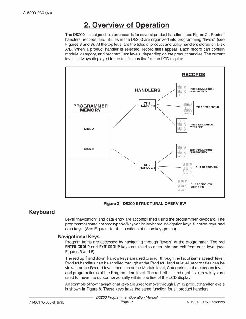
2. Overview of OperationThe D5200 is designed to store records for several product handlers (see Figure 2). Producthandlers, records, and utilities in the D5200 are organized into programming "levels" (seeFigures 3 and 8). At the top level are the titles of product and utility handlers stored on DiskA/B. When a product handler is selected, record titles appear. Each record can containmodule, category, and program item levels, depending on the product handler. The currentlevel is always displayed in the top "status line" of the LCD display.
Prog Item 1 YesProg Item 2 NoProg Item 3 2Prog Item 4 YesProg Item 5 NoProg Item 6 2Prog Item 7 YesProg Item 8 NoProg Item 8 2
7112 COMMERCIALSUPERVISED
Prog Item 1 YesProg Item 2 NoProg Item 3 2Prog Item 4 YesProg Item 5 NoProg Item 6 2Prog Item 7 YesProg Item 8 NoProg Item 8 2
7112 RESIDENTIAL
Prog Item 1 YesProg Item 2 NoProg Item 3 2Prog Item 4 YesProg Item 5 NoProg Item 6 2Prog Item 7 YesProg Item 8 NoProg Item 8 2
7112 RESIDENTIALWITH FIRE
Prog Item 1 YesProg Item 2 NoProg Item 3 2Prog Item 4 YesProg Item 5 NoProg Item 6 2Prog Item 7 YesProg Item 8 NoProg Item 8 2
8112 COMMERCIALSUPERVISED
Prog Item 1 YesProg Item 2 NoProg Item 3 2Prog Item 4 YesProg Item 5 NoProg Item 6 2Prog Item 7 YesProg Item 8 NoProg Item 8 2
8112 RESIDENTIAL
Prog Item 1 YesProg Item 2 NoProg Item 3 2Prog Item 4 YesProg Item 5 NoProg Item 6 2Prog Item 7 YesProg Item 8 NoProg Item 8 2
8112 RESIDENTIALWITH FIRE
DISK A
HANDLERS
7112HANDLER
8112HANDLER
RECORDS
PROGRAMMERMEMORY
DISK B
Figure 2: D5200 STRUCTURAL OVERVIEW
KeyboardLevel "navigation" and data entry are accomplished using the programmer keyboard. Theprogrammer contains three types of keys on its keyboard: navigation keys, function keys, anddata keys. (See Figure 1 for the locations of these key groups).
Navigational KeysProgram items are accessed by navigating through "levels" of the programmer. The redENTER GROUP and EXIT GROUP keys are used to enter into and exit from each level (seeFigures 3 and 8).
The red up ↑ and down ↓ arrow keys are used to scroll through the list of items at each level.Product handlers can be scrolled through at the Product Handler level, record titles can beviewed at the Record level, modules at the Module level, Categories at the category level,and program items at the Program Item level. The red left ← and right → arrow keys areused to move the cursor horizontally within one line of the LCD display.
An example of how navigational keys are used to move through D7112 product handler levelsis shown in Figure 8. These keys have the same function for all product handlers.
070
D5200 Programmer Operation ManualPage 8 © 1991-1995 Radionics74-06176-000-B 9/95
A-5200-030-80
PRODUCTHANDLERS
DISKSTAT
2071
4112
6112
636
8112
SECURITY
UPDATE
DELETE
5200 OFF
Current DiskSizeKilobytesFreeKilobytes
Passwords U1PasswordUser#: U#PasswordU#PasswordEnableU#Delete RecordU#Delete HandlerU#Edit LockcodesU#Edit PaswordsU#Edit Vis/InvisU#Update HandlerU#Replace RecordU#Format DiskU#Lock Record
Lockcodes Primary LockLock#: Lockcode#:
Format Disk Disk: B
Time Out:
HandName:Include Help: Phone:Mode: A -> B B -> A A->TELCO TELCO->A B->TELCO TELCO->B A->RS232 RS232->A B->RS232 RS232->B
HandName:HelpName:
Program Items
Modules
Modules
Program Items
Modules
2071 Handler Records
4112 Handler Records
6112 Handler Records
636 Handler Records
8112 Handler Records
Program Items
Program Items
Program Items
ENTERGROUP
ENTERGROUP
ENTERGROUP
ENTERGROUP
ENTERGROUP
EXITGROUP
EXITGROUP
EXITGROUP
EXITGROUP
EXITGROUP
EXITGROUP
7112 Modules7112 Handler Records Categories Program Items
UTILITIES
NEWRECORDDELETECOPYVISMODELOCKRECORD
Same for all handlers.
SEND(LOAD)
RECV(COPY)
12
33
41 4141
9
27
29
17
2423
2526
14 17 18
10 101010
30
32
39
11
42
3434
3935
3539
37383738
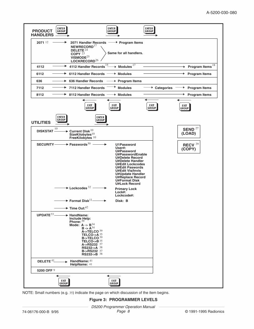
Figure 3: PROGRAMMER LEVELS
NOTE: Small numbers (e.g. 35) indicate the page on which discussion of the item begins.
080
D5200 Programmer Operation ManualPage 9 © 1991-1995 Radionics74-06176-000-B 9/95
A-5200-030-80
Function KeysSix function keys simplify the use of the programmer.
ON: The red ON key switches the programmer on. This key does not power down theprogrammer. The D5200 is switched off by selecting 5200 OFF in the PRODUCT HANDLERSmenu, or it powers down automatically after the programmed Time Out time has elapsed.
HELP: The red HELP key switches the programmer into help mode. (See the Help Modechapter for more information.)
CANCEL: The red CANCEL key erases unENTERed program item data and replaces it withthe previously entered data.
CLEAR: The red CLEAR key erases unENTERed or ENTERED program item data, andreplaces it with blank spaces.
RECV (COPY) : The red RECV (COPY) key initiates a transfer of data from a product into theD5200 Programmer.
SEND (LOAD): The red SEND (LOAD) key initiates a transfer of data from the D5200 Programmerto another product.
Data KeysThe white keys on the keyboard are used for data entry.
Helpful TonesThe D5200 Programmer emits four distinct sounds, which notify the user of key presses, dataacceptance/rejection, and system errors.
CLICKA short, sharp click occurs every time a key is pressed. The programmer does not click whenthe ON, CAP LOCK, and SHIFT keys are pressed.
PIPA short, single frequency tone indicates that the key pressed or data entered was accepted.
TWEEDLEA quick series of pips indicates that the key pressed or data entered was invalid orinappropriate.
BUZZA sour, flat tone indicates a system error, except when entering a product. Panel notconnected to D5200, low battery condition, programmed Time Out elapsed, changing panelseries type, deleting handlers and records are examples.
090
D5200 Programmer Operation ManualPage 10 © 1991-1995 Radionics74-06176-000-B 9/95
A-5200-030-100
3. Disk OperationsThe D5200 contains memory which holds programmer data. This memory includes internalbattery-backed RAM chips which are permanently attached to the D5200 circuit board, andremovable RAM cards.
• The internal battery-backed RAM is referred to as disk A.• The removable RAM card is referred to as disk B.
Even though data may be stored on several RAM cards, the RAM card which is currentlyplugged into the programmer is always considered disk B.
Disk StatusThe size of a disk and the amount of memory currently available on a disk can be viewed usingthe DISKSTAT feature. To view this information, scroll to DISKSTAT from the ProductHandlers menu using the red ↓ or ↑ keys, and press the red ENTER GROUP key.
Current Disk: Disk A is the internal battery-backed RAM. Disk B is the removable RAMcard. The programmer can display data from only one disk at a time (the disk indicatedby Current Disk). See Changing the Current Disk to set up the programmer to displaydata from a different disk.
SizeKilobytes: Each disk can hold a certain amount of data, expressed in units of bytes,kilobytes (K), or Megabytes (Mb). 1024 bytes = 1 K, 1024K = 1 Mb. The total amount ofmemory of the Current Disk (A or B) is displayed in SizeKilobytes.
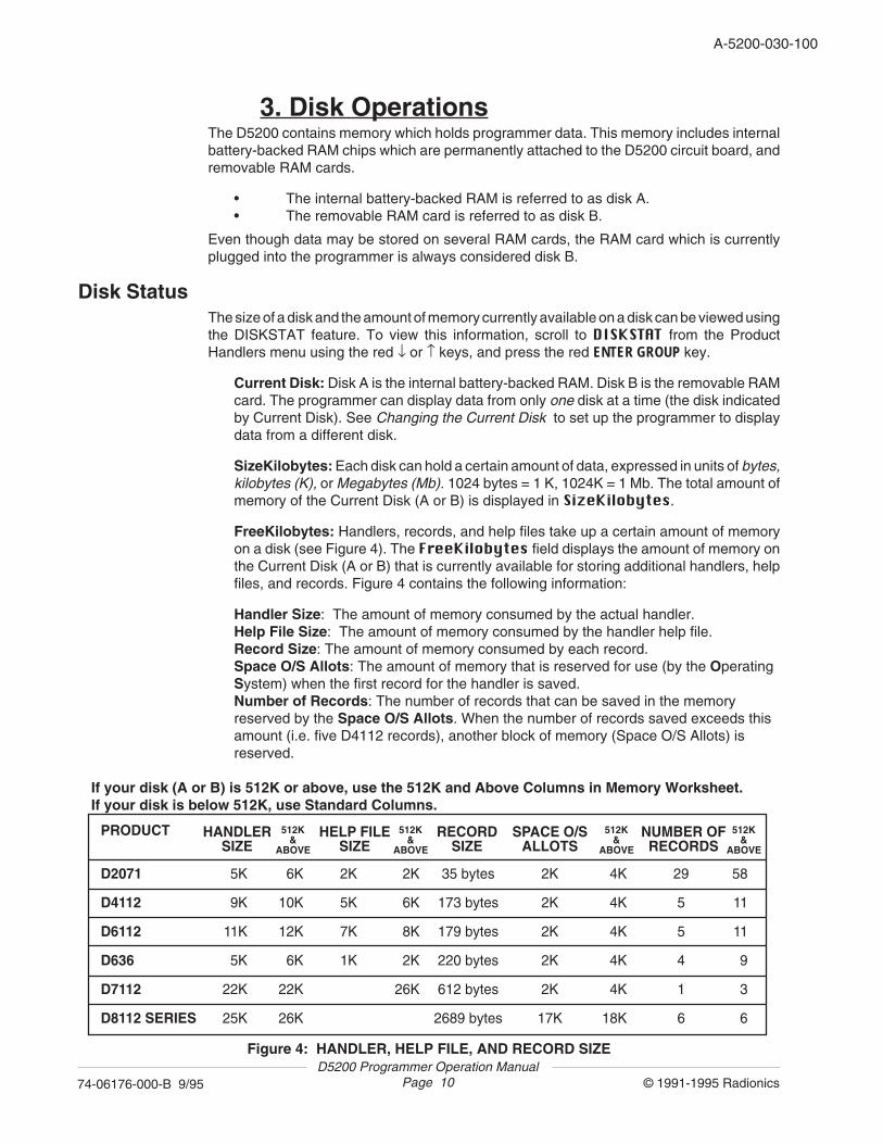
FreeKilobytes: Handlers, records, and help files take up a certain amount of memoryon a disk (see Figure 4). The FreeKilobytes field displays the amount of memory onthe Current Disk (A or B) that is currently available for storing additional handlers, helpfiles, and records. Figure 4 contains the following information:
Handler Size: The amount of memory consumed by the actual handler.Help File Size: The amount of memory consumed by the handler help file.Record Size: The amount of memory consumed by each record.Space O/S Allots: The amount of memory that is reserved for use (by the OperatingSystem) when the first record for the handler is saved.Number of Records: The number of records that can be saved in the memoryreserved by the Space O/S Allots. When the number of records saved exceeds thisamount (i.e. five D4112 records), another block of memory (Space O/S Allots) isreserved.
PRODUCT
D2071
D4112
D6112
D636
D7112
D8112 SERIES
5K
9K
11K
5K
22K
25K
HANDLERSIZE
35 bytes
173 bytes
179 bytes
220 bytes
612 bytes
2689 bytes
RECORDSIZE
HELP FILESIZE
SPACE O/SALLOTS
NUMBER OFRECORDS
2K
2K
2K
2K
2K
17K
29
5
5
4
1
6
2K
5K
7K
1K
512K &
ABOVE
512K &
ABOVE
512K &
ABOVE
512K &
ABOVE
6K
10K
12K
6K
22K
26K
2K
6K
8K
2K
26K
4K
4K
4K
4K
4K
18K
58
11
11
9
3
6
Figure 4: HANDLER, HELP FILE, AND RECORD SIZE
If your disk (A or B) is 512K or above, use the 512K and Above Columns in Memory Worksheet.If your disk is below 512K, use Standard Columns.
D5200 Programmer Operation ManualPage 11 © 1991-1995 Radionics74-06176-000-B 9/95
A-5200-030-100
Changing the Current DiskAt the Current Disk prompt in the DISKSTAT display, press the letter on the keyboardwhich corresponds to the desired disk. Press the white ENTER key. (NOTE: The SPACE barcannot be used to toggle between available disk drives.) The message LOGGED ON DISK!is displayed, and the SizeKilobytes and FreeKilobytes fields are updated to reflect the statusof the new Current Disk.
To exit the DISKSTAT display, press the red EXIT GROUP key. The cursor returns to theProduct Handlers level of the Current Disk. NOTE: When the Programmer is switched on, theCurrent Disk always defaults to disk A.
Formatting a DiskThe D5200 Programmer can be used to format the internal battery-backed RAM memory(Disk A) and the removable RAM cards (Disk B). As shipped, the internal RAM Disk A isalready formatted. Each new removable disk (Disk B) used with the programmer must beformatted. NOTE: This feature is password dependent . If the programmer is logged onto witha password that does not have the authority to format disks, the message ACCESS DENIEDis displayed when trying to access this feature.
WARNING: All information stored on the disk will be lost when the disk is formatted!
1. Scroll to SECURITY in the Product Handlers menu using the red ↓ or ↑ keys, and pressthe red ENTER GROUP key.
2. Scroll to the FormatDisk item in the SECURITY menu using the red ↓ or ↑ keys, andpress the red ENTER GROUP key.
3. The FormatDisk menu is displayed. Select the disk to be formatted by pressing thecorresponding disk letter and then pressing the white ENTER key. A warning messageis displayed. To abort the disk format process, type N. To continue with the formatprocess, press Y. If the format is successful, the message RAM FORMAT COMPLETEDis displayed.
FORMAT ABORTED: This message is displayed if N was typed at the Continue?prompt, or if disk formatting failed.
RAM CARD NOT PRESENT: This message is displayed if Disk B was selected forformatting and the RAM card is not plugged into the programmer.
RAM DISK PROTECTED: This message is displayed if Disk B was selected forformatting and the RAM card in the programmer is write-protected.
4. To exit the FormatDisk display, press the red EXIT GROUP key. The cursor returns tothe SECURITY menu.
5. To exit the SECURITY menu, press the red EXIT GROUP key. The cursor returns to theProduct Handlers level.
D5200 Programmer Operation ManualPage 12 © 1991-1995 Radionics74-06176-000-B 9/95
A-5200-030-120
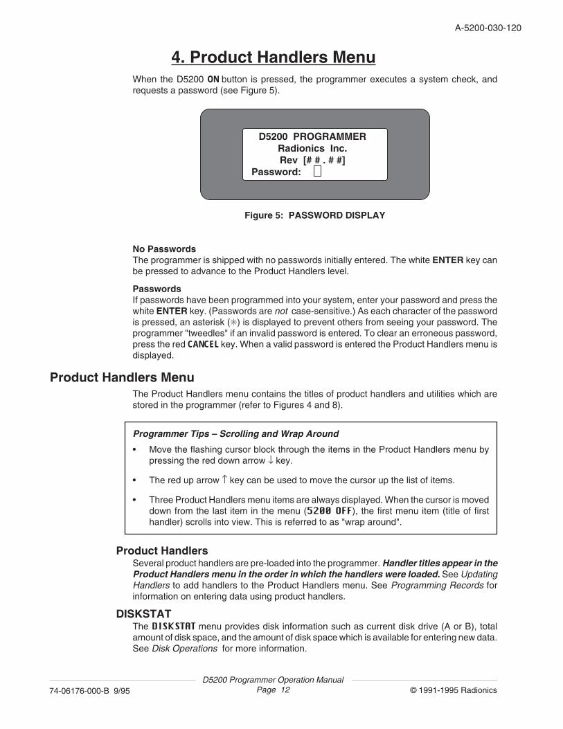
4. Product Handlers MenuWhen the D5200 ON button is pressed, the programmer executes a system check, andrequests a password (see Figure 5).
D5200 PROGRAMMERRadionics Inc.Rev [# # . # #]
Password:
Figure 5: PASSWORD DISPLAY
No PasswordsThe programmer is shipped with no passwords initially entered. The white ENTER key canbe pressed to advance to the Product Handlers level.
PasswordsIf passwords have been programmed into your system, enter your password and press thewhite ENTER key. (Passwords are not case-sensitive.) As each character of the passwordis pressed, an asterisk (✳) is displayed to prevent others from seeing your password. Theprogrammer "tweedles" if an invalid password is entered. To clear an erroneous password,press the red CANCEL key. When a valid password is entered the Product Handlers menu isdisplayed.
Product Handlers MenuThe Product Handlers menu contains the titles of product handlers and utilities which arestored in the programmer (refer to Figures 4 and 8).
Programmer Tips – Scrolling and Wrap Around
• Move the flashing cursor block through the items in the Product Handlers menu bypressing the red down arrow ↓ key.
• The red up arrow ↑ key can be used to move the cursor up the list of items.
• Three Product Handlers menu items are always displayed. When the cursor is moveddown from the last item in the menu (5200 OFF), the first menu item (title of firsthandler) scrolls into view. This is referred to as "wrap around".
Product HandlersSeveral product handlers are pre-loaded into the programmer. Handler titles appear in theProduct Handlers menu in the order in which the handlers were loaded. See UpdatingHandlers to add handlers to the Product Handlers menu. See Programming Records forinformation on entering data using product handlers.
DISKSTATThe DISKSTAT menu provides disk information such as current disk drive (A or B), totalamount of disk space, and the amount of disk space which is available for entering new data.See Disk Operations for more information.

D5200 Programmer Operation ManualPage 13 © 1991-1995 Radionics74-06176-000-B 9/95
A-5200-030-120
SECURITYThe SECURITY menu includes items for programming passwords and panel lockcodes,formatting disks, and programming the D5200 automatic power-down time. See the Passwordsand Lockcodes sections for more information.
UPDATEThis menu is provided for updating (copying) product handlers between disks on the sameprogrammer, or between the disks of two different programmers via the phone lines or RS-232 interface. See Updating Handlers for more information.
DELETEThis menu item allows product handlers and help files to be deleted from D5200 memory. SeeDeleting Handlers for more information.
5200 OFFThis menu item is used to power down the programmer. To turn off the D5200, move thecursor to 5200 OFF and press the red ENTER GROUP key.
NOTE: The D5200 powers down automatically if no keys have been pressed for the amountof time programmed in the programmer SECURITY menu Time Out parameter. SeeProgrammer TimeOut for more information.
Selecting a Product Handlers Menu ItemUse the red ↑ and ↓ arrow keys to move the cursor through the list of items in the ProductHandlers menu. When the cursor flashes on the desired item, press the red ENTER GROUPkey. The next chapters of this manual describe how to "navigate" within each item in theProduct Handlers menu.
Exiting the Product Handlers MenuThe cursor can be returned to the password display from the Product Handlers level bypressing the red EXIT GROUP key. This returns the display to the Password entry prompt.
The programmer can be powered down by returning to the Product Handlers level andselecting the 5200 OFF prompt.
D5200 Programmer Operation ManualPage 14 © 1991-1995 Radionics74-06176-000-B 9/95
A-5200-030-140
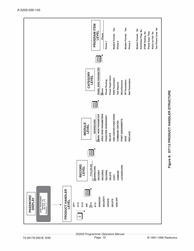
5. Programming RecordsThe example in this chapter shows how to program a record for a D7112 Control/Communicator. The same principles apply to the programming of other product handlers.Refer to Figure 8, which is a "map" of the D7112 Product Handler.
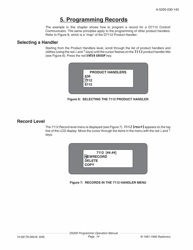
Selecting a HandlerStarting from the Product Handlers level, scroll through the list of product handlers andutilities (using the red ↓ and ↑ keys) until the cursor flashes on the 7112 product handler title(see Figure 6). Press the red ENTER GROUP key.
PRODUCT HANDLERS63671126112
Figure 6: SELECTING THE 7112 PRODUCT HANDLER
7112 [##.##]NEWRECORDDELETECOPY
Figure 7: RECORDS IN THE 7112 HANDLER MENU
Record LevelThe 7112 Record level menu is displayed (see Figure 7). 7112 [rev#] appears on the topline of the LCD display. Move the cursor through the items in the menu with the red ↓ and ↑keys.
D5200 Programmer Operation ManualPage 15 © 1991-1995 Radionics74-06176-000-B 9/95
A-5200-030-140
PR
OD
UC
T H
AN
DL
ER
LE
VE
L
2071
4112
6112
636
7112
8112
DIS
KS
TAT
SE
CU
RIT
Y
UP
DA
TE
DE
LE
TE
5200
OF
F
ENTE
RG
ROUP
↓
711
2 [#
#.##
]
NE
WR
EC
OR
D
RE
CO
RD
1
RE
CO
RD
2
RE
CO
RD
3
DE
LE
TE
CO
PY
VIS
MO
DE
LO
CK
RE
CO
RD
RE
CO
RD
LE
VE
L
ENTE
RG
ROUP
NE
WR
EC
OR
D
PAN
EL
WID
E P
AR
AM
ET
ER
AR
EA
WID
E P
AR
AM
ET
ER
S
PAS
SC
OD
E W
OR
KS
HE
ET
RE
LA
YS
CM
D C
EN
TE
R F
UN
CT
ION
S
CO
MM
AN
D C
EN
TE
R
PO
INT
AS
SIG
NM
EN
TS
SA
VE
RE
PL
AC
E
MO
DU
LE
LE
VE
L
ENTE
RG
ROUP
PAN
EL
WID
E P
AR
AM
ET
ER
Ph
on
e
Ph
on
e R
ou
tin
g
Po
wer
Su
per
visi
on
RA
M P
aram
eter
s
Test
Rep
ort
s
Mis
cella
neo
us
RF
Par
amet
ers
Bel
l Par
amet
ers
CA
TE
GO
RY
LE
VE
L
ENTE
RG
ROUP
P
ho
ne
Ph
on
e 1
Mo
dem
Fo
rmat
Y
es
Ph
on
e 2
Mo
dem
Fo
rmat
Y
es
Ph
on
e 3
Mo
dem
Fo
rmat
N
o
Po
int/
Use
r F
lag
No
DT
MF
Dia
ling
No
Ph
on
e S
up
v Ti
me
Ala
rm o
n F
ail
No
Two
Ph
on
e L
ines
No
PR
OG
RA
M IT
EM
LE
VE
L
PAS
SW
OR
DD
ISP
LA
Y
D52
00 P
RO
GR
AM
ME
RR
adio
nic
s In
c.R
ev [
# #
. # #
]P
assw
ord
:
Fig
ure
8:
D71
12 P
RO
DU
CT
HA
ND
LE
R S
TR
UC
TU
RE
D5200 Programmer Operation ManualPage 16 © 1991-1995 Radionics74-06176-000-B 9/95
A-5200-030-160
The handler title is always shown in the top line of the LCD display at the Record level. Threeadditional items are always displayed below the product handler title. When the cursor ismoved down from the last item in the menu (LOCKRECORD), the first menu item (title of firstD7112 record) scrolls into view. The 7112 Record level menu contains the following items:
RecordsThe titles of D7112 records appear at the top of the Record level menu.
NEWRECORDNEWRECORD is used to create new records.
TIMEOUTSAVEThis title is included in the list only if a record was still open when the D5200 Programmer wentinto a power-down timeout. If a timeout record exists, the programmer beeps when thehandler is entered, and SAVE TIMEOUT RECORD appears among the items in the display.See the TimeOut Save section in this chapter for more information.
DELETEThis utility is provided for deleting unwanted records. See Deleting a Record in this chapterfor more information.
COPYThis utility is provided for copying the programmed parameters from an existing record andsaving the data under a different name. See Copying Records in this chapter for moreinformation.
VISMODEThis utility is used to make selected program items in this handler invisible. See MakingProgram Items Invisible in this chapter for more information.
LOCKRECORDThis utility is provided to prevent modifications to specific records. See Locking Records inthis chapter for more information.
D5200 Programmer Operation ManualPage 17 © 1991-1995 Radionics74-06176-000-B 9/95
A-5200-030-160
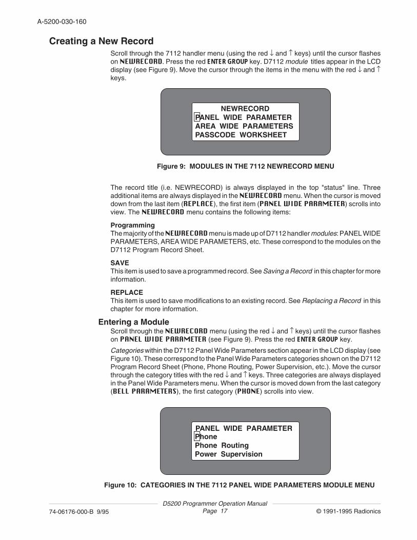
Creating a New RecordScroll through the 7112 handler menu (using the red ↓ and ↑ keys) until the cursor flasheson NEWRECORD. Press the red ENTER GROUP key. D7112 module titles appear in the LCDdisplay (see Figure 9). Move the cursor through the items in the menu with the red ↓ and ↑keys.
PANEL WIDE PARAMETERPhonePhone RoutingPower Supervision
Figure 10: CATEGORIES IN THE 7112 PANEL WIDE PARAMETERS MODULE MENU
The record title (i.e. NEWRECORD) is always displayed in the top "status" line. Threeadditional items are always displayed in the NEWRECORD menu. When the cursor is moveddown from the last item (REPLACE), the first item (PANEL WIDE PARAMETER) scrolls intoview. The NEWRECORD menu contains the following items:
ProgrammingThe majority of the NEWRECORD menu is made up of D7112 handler modules: PANEL WIDEPARAMETERS, AREA WIDE PARAMETERS, etc. These correspond to the modules on theD7112 Program Record Sheet.
SAVEThis item is used to save a programmed record. See Saving a Record in this chapter for moreinformation.
REPLACEThis item is used to save modifications to an existing record. See Replacing a Record in thischapter for more information.
Entering a ModuleScroll through the NEWRECORD menu (using the red ↓ and ↑ keys) until the cursor flasheson PANEL WIDE PARAMETER (see Figure 9). Press the red ENTER GROUP key.
Categories within the D7112 Panel Wide Parameters section appear in the LCD display (seeFigure 10). These correspond to the Panel Wide Parameters categories shown on the D7112Program Record Sheet (Phone, Phone Routing, Power Supervision, etc.). Move the cursorthrough the category titles with the red ↓ and ↑ keys. Three categories are always displayedin the Panel Wide Parameters menu. When the cursor is moved down from the last category(BELL PARAMETERS), the first category (PHONE) scrolls into view.
NEWRECORDPANEL WIDE PARAMETERAREA WIDE PARAMETERSPASSCODE WORKSHEET
Figure 9: MODULES IN THE 7112 NEWRECORD MENU
D5200 Programmer Operation ManualPage 18 © 1991-1995 Radionics74-06176-000-B 9/95
A-5200-030-180
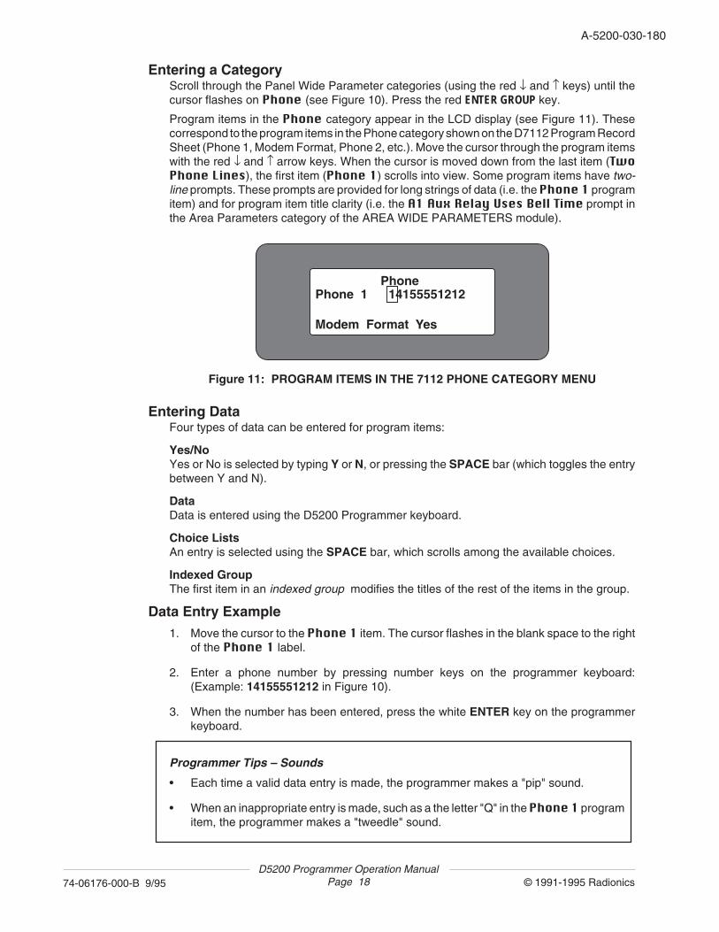
Entering a CategoryScroll through the Panel Wide Parameter categories (using the red ↓ and ↑ keys) until thecursor flashes on Phone (see Figure 10). Press the red ENTER GROUP key.
Program items in the Phone category appear in the LCD display (see Figure 11). Thesecorrespond to the program items in the Phone category shown on the D7112 Program RecordSheet (Phone 1, Modem Format, Phone 2, etc.). Move the cursor through the program itemswith the red ↓ and ↑ arrow keys. When the cursor is moved down from the last item (TwoPhone Lines), the first item (Phone 1) scrolls into view. Some program items have two-line prompts. These prompts are provided for long strings of data (i.e. the Phone 1 programitem) and for program item title clarity (i.e. the A1 Aux Relay Uses Bell Time prompt inthe Area Parameters category of the AREA WIDE PARAMETERS module).
Entering DataFour types of data can be entered for program items:
Yes/NoYes or No is selected by typing Y or N, or pressing the SPACE bar (which toggles the entrybetween Y and N).
DataData is entered using the D5200 Programmer keyboard.
Choice ListsAn entry is selected using the SPACE bar, which scrolls among the available choices.
Indexed GroupThe first item in an indexed group modifies the titles of the rest of the items in the group.
Data Entry Example1. Move the cursor to the Phone 1 item. The cursor flashes in the blank space to the right
of the Phone 1 label.
2. Enter a phone number by pressing number keys on the programmer keyboard:(Example: 14155551212 in Figure 10).
3. When the number has been entered, press the white ENTER key on the programmerkeyboard.
Programmer Tips – Sounds
• Each time a valid data entry is made, the programmer makes a "pip" sound.
• When an inappropriate entry is made, such as a the letter "Q" in the Phone 1 programitem, the programmer makes a "tweedle" sound.
PhonePhone 1 14155551212 Modem Format Yes
Figure 11: PROGRAM ITEMS IN THE 7112 PHONE CATEGORY MENU
D5200 Programmer Operation ManualPage 19 © 1991-1995 Radionics74-06176-000-B 9/95
A-5200-030-180
Programmer Tips – Making CorrectionsThe following keys can be used to change data entered for a program item:
• Use the white BACKSPACE key on the programmer keyboard to erase characters.
• Use the red ← and → arrow keys to move the cursor to any character in the entry.(The arrow keys do not erase characters.)
• Use the red CLEAR key to erase the entire entry.
• Use the red CANCEL key to return the entry to its default entry.
Yes/No Entry ExampleMove the cursor to Modem Format. The cursor flashes on the default entry Yes.
Press the white SPACE bar on the keyboard to toggle the entry to Yes. Pressing the SPACEbar again toggles the entry back to No. Yes and No entries can also be achieved by pressingthe Y key or the N key on the keyboard.
When the appropriate Yes/No entry has been selected, press the white ENTER key on theprogrammer keyboard. The cursor moves down to the next program item.
Choice List Entry ExampleUsing the red ↓ key, move the cursor to Phone Supv Time. The cursor flashes in the blankspace to the right of the Phone Supv Time label.
Press the white SPACE bar on the keyboard to scroll through the programming choicesavailable: 2Min, 4Min, 8Min, blank (No Supervision).
When the appropriate entry has been selected, press the white ENTER key on theprogrammer keyboard. The cursor moves down to the next program item.
Programmer Tip – Choice List Data EntryOnly the entries displayed using the SPACE bar will be accepted by the programmer forchoice list entries. If numbers or letters are typed in using the keyboard, the programmerwill "tweedle" when the ENTER key is pressed.
To view valid choices, move the cursor back to the first character, using the red CANCEL,CLEAR, or ← key, and press the SPACE bar.
Exiting a CategoryTo exit a category (i.e. Phone), press the red EXIT GROUP key. The cursor returns to themodule level, and flashes on the next module title AREA WIDE PARAMETERS.
NOTE: The programmer will "tweedle" if the cursor is flashing on program item data that hasnot been entered. Press the white ENTER key to enter data or the red CANCEL key to returnthe previous entry, and then press the red EXIT GROUP key.
D5200 Programmer Operation ManualPage 20 © 1991-1995 Radionics74-06176-000-B 9/95
A-5200-030-200
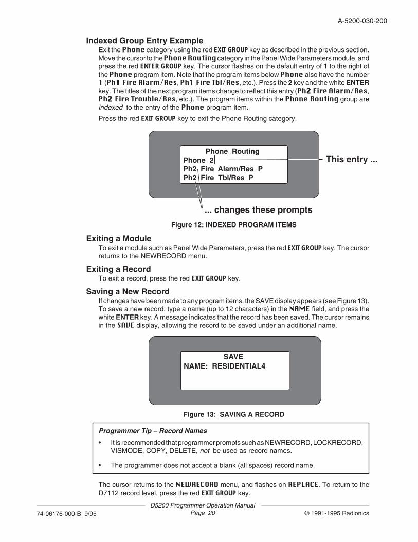
Indexed Group Entry ExampleExit the Phone category using the red EXIT GROUP key as described in the previous section.Move the cursor to the Phone Routing category in the Panel Wide Parameters module, andpress the red ENTER GROUP key. The cursor flashes on the default entry of 1 to the right ofthe Phone program item. Note that the program items below Phone also have the number1 (Ph11111 Fire Alarm/Res, Ph11111 Fire Tbl/Res, etc.). Press the 2 key and the white ENTERkey. The titles of the next program items change to reflect this entry (Ph22222 Fire Alarm/Res,Ph22222 Fire Trouble/Res, etc.). The program items within the Phone Routing group areindexed to the entry of the Phone program item.
Press the red EXIT GROUP key to exit the Phone Routing category.
Phone RoutingPhone 2Ph2 Fire Alarm/Res P Ph2 Fire Tbl/Res P
This entry ...
... changes these prompts
Figure 12: INDEXED PROGRAM ITEMS
SAVENAME: RESIDENTIAL4
Figure 13: SAVING A RECORD
Programmer Tip – Record Names
• It is recommended that programmer prompts such as NEWRECORD, LOCKRECORD,VISMODE, COPY, DELETE, not be used as record names.
• The programmer does not accept a blank (all spaces) record name.
The cursor returns to the NEWRECORD menu, and flashes on REPLACE. To return to theD7112 record level, press the red EXIT GROUP key.
Exiting a ModuleTo exit a module such as Panel Wide Parameters, press the red EXIT GROUP key. The cursorreturns to the NEWRECORD menu.
Exiting a RecordTo exit a record, press the red EXIT GROUP key.
Saving a New RecordIf changes have been made to any program items, the SAVE display appears (see Figure 13).To save a new record, type a name (up to 12 characters) in the NAME field, and press thewhite ENTER key. A message indicates that the record has been saved. The cursor remainsin the SAVE display, allowing the record to be saved under an additional name.

D5200 Programmer Operation ManualPage 21 © 1991-1995 Radionics74-06176-000-B 9/95
A-5200-030-200
Programmer Tip – Saving and Replacing RecordsWhenever changes have been made to record data, the programmer always goes to theSAVE display to provide the user with an opportunity to save the changes under the same(or different) name.
When the SAVE display is exited, the cursor automatically flashes on the REPLACE itemin the menu, to provide the user with another chance to save any changes that have beenmade to the record.
Exiting a HandlerTo return to the Product Handlers level, press the red EXIT GROUP key.
Programmer Tip – Creating New Records from a TemplateA programmed record ("template") can be used to create new records. (It is not necessaryto always start with NEWRECORD.) A "template" is especially useful when only a few itemsneed to be changed to "customize" an existing record. See the next section Editing aRecord for more information. NOTE: NEWRECORD can be unlocked.
Editing a RecordTo make changes to an existing record:
1. Scroll to the appropriate product handler from the Product Handlers menu using the red↓ or ↑ keys, and press the red ENTER GROUP key.
2. Scroll to the appropriate record title using the red ↓ or ↑ keys, and press the red ENTERGROUP key.
3. For product handlers with modules: Scroll to the appropriate module using the red ↓ or↑ keys, and press the red ENTER GROUP key.
4. For modules with categories: Scroll to the appropriate category using the red ↓ or ↑ keys,and press the red ENTER GROUP key.
5. Scroll to the appropriate program item using the red ↓ or ↑ keys, and edit the entry. Pressthe white ENTER key to enter the new data.
6. For modules with categories: Press the red EXIT GROUP key to return to the Categorieslevel.
7. For product handlers with modules: Press the red EXIT GROUP key to return to theModules level.
8. Press the red EXIT GROUP key to exit from the record. The SAVE display appears ifchanges have been made to any program item entries in the record.
SAVING as a DIFFERENT Record: To save the edited record under a new name, typea name (up to 12 characters) in the NAME field, and press the white ENTER key. Amessage indicates that the record has been saved. The cursor remains in the SAVEdisplay, allowing the record to be saved (duplicated) under another name. Press the redEXIT GROUP key to return to the Record level.
D5200 Programmer Operation ManualPage 22 © 1991-1995 Radionics74-06176-000-B 9/95
A-5200-030-220
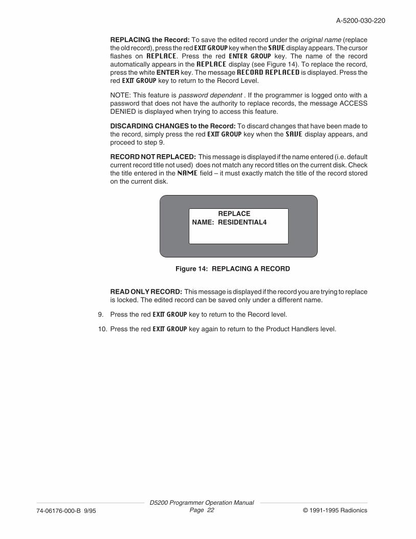
REPLACING the Record: To save the edited record under the original name (replacethe old record), press the red EXIT GROUP key when the SAVE display appears. The cursorflashes on REPLACE. Press the red ENTER GROUP key. The name of the recordautomatically appears in the REPLACE display (see Figure 14). To replace the record,press the white ENTER key. The message RECORD REPLACED is displayed. Press thered EXIT GROUP key to return to the Record Level.
NOTE: This feature is password dependent . If the programmer is logged onto with apassword that does not have the authority to replace records, the message ACCESSDENIED is displayed when trying to access this feature.
DISCARDING CHANGES to the Record: To discard changes that have been made tothe record, simply press the red EXIT GROUP key when the SAVE display appears, andproceed to step 9.
RECORD NOT REPLACED: This message is displayed if the name entered (i.e. defaultcurrent record title not used) does not match any record titles on the current disk. Checkthe title entered in the NAME field – it must exactly match the title of the record storedon the current disk.
REPLACENAME: RESIDENTIAL4
Figure 14: REPLACING A RECORD
READ ONLY RECORD: This message is displayed if the record you are trying to replaceis locked. The edited record can be saved only under a different name.
9. Press the red EXIT GROUP key to return to the Record level.
10. Press the red EXIT GROUP key again to return to the Product Handlers level.
D5200 Programmer Operation ManualPage 23 © 1991-1995 Radionics74-06176-000-B 9/95
A-5200-030-220
Copying a RecordTo copy a record (save it under a different name):
1. Select a product handler from the Product Handlers level using the red ↓ or ↑ keys, andpress the red ENTER GROUP key.
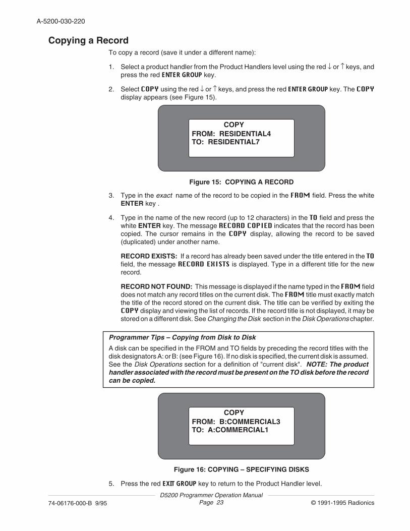
2. Select COPY using the red ↓ or ↑ keys, and press the red ENTER GROUP key. The COPYdisplay appears (see Figure 15).
COPYFROM: RESIDENTIAL4TO: RESIDENTIAL7
Figure 15: COPYING A RECORD
3. Type in the exact name of the record to be copied in the FROM field. Press the whiteENTER key .
4. Type in the name of the new record (up to 12 characters) in the TO field and press thewhite ENTER key. The message RECORD COPIED indicates that the record has beencopied. The cursor remains in the COPY display, allowing the record to be saved(duplicated) under another name.
RECORD EXISTS: If a record has already been saved under the title entered in the TOfield, the message RECORD EXISTS is displayed. Type in a different title for the newrecord.
RECORD NOT FOUND: This message is displayed if the name typed in the FROM fielddoes not match any record titles on the current disk. The FROM title must exactly matchthe title of the record stored on the current disk. The title can be verified by exiting theCOPY display and viewing the list of records. If the record title is not displayed, it may bestored on a different disk. See Changing the Disk section in the Disk Operations chapter.
Programmer Tips – Copying from Disk to Disk
A disk can be specified in the FROM and TO fields by preceding the record titles with thedisk designators A: or B: (see Figure 16). If no disk is specified, the current disk is assumed.See the Disk Operations section for a definition of "current disk". NOTE: The producthandler associated with the record must be present on the TO disk before the recordcan be copied.
5. Press the red EXIT GROUP key to return to the Product Handler level.
COPYFROM: B:COMMERCIAL3TO: A:COMMERCIAL1
Figure 16: COPYING – SPECIFYING DISKS
D5200 Programmer Operation ManualPage 24 © 1991-1995 Radionics74-06176-000-B 9/95
A-5200-030-240
Deleting a RecordFollow the steps below to delete a record. NOTE: This feature is password dependent. If theprogrammer is logged onto with a password that does not have the authority to deleterecords, the message ACCESS DENIED is displayed when trying to access this feature.
1. Select the appropriate product handler from the Product Handlers menu using the red ↓or ↑ keys, and press the red ENTER GROUP key.
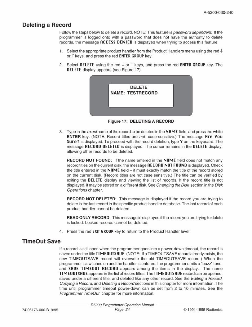
2. Select DELETE using the red ↓ or ↑ keys, and press the red ENTER GROUP key. TheDELETE display appears (see Figure 17).
DELETENAME: TESTRECORD
Figure 17: DELETING A RECORD
3. Type in the exact name of the record to be deleted in the NAME field, and press the whiteENTER key. (NOTE: Record titles are not case-sensitive.) The message Are YouSure? is displayed. To proceed with the record deletion, type Y on the keyboard. Themessage RECORD DELETED is displayed. The cursor remains in the DELETE display,allowing other records to be deleted.
RECORD NOT FOUND: If the name entered in the NAME field does not match anyrecord titles on the current disk, the message RECORD NOT FOUND is displayed. Checkthe title entered in the NAME field – it must exactly match the title of the record storedon the current disk. (Record titles are not case sensitive.) The title can be verified byexiting the DELETE display and viewing the list of records. If the record title is notdisplayed, it may be stored on a different disk. See Changing the Disk section in the DiskOperations chapter.
RECORD NOT DELETED: This message is displayed if the record you are trying todelete is the last record in the specific product handler database. The last record of eachproduct handler cannot be deleted.
READ ONLY RECORD: This message is displayed if the record you are trying to deleteis locked. Locked records cannot be deleted.
4. Press the red EXIT GROUP key to return to the Product Handler level.
TimeOut SaveIf a record is still open when the programmer goes into a power-down timeout, the record issaved under the title TIMEOUTSAVE. (NOTE: If a TIMEOUTSAVE record already exists, thenew TIMEOUTSAVE record will overwrite the old TIMEOUTSAVE record.) When theprogrammer is switched on and the handler is entered, the programmer emits a "buzz" tone,and SAVE TIMEOUT RECORD appears among the items in the display. The nameTIMEOUTSAVE appears in the list of record titles. The TIMEOUTSAVE record can be opened,saved under a different title, and deleted like any other record. See the Editing a Record,Copying a Record, and Deleting a Record sections in this chapter for more information. Thetime until programmer timeout power-down can be set from 2 to 10 minutes. See theProgrammer TimeOut chapter for more information.
D5200 Programmer Operation ManualPage 25 © 1991-1995 Radionics74-06176-000-B 9/95
A-5200-030-240
Making Program Items Invisible (VISMODE)Program items, categories, and modules in each handler can be made invisible usingVISMODE. NOTE: This feature is password dependent. If the programmer is logged ontowith a password that does not have the authority to make program items invisible, themessage ACCESS DENIED is displayed when trying to access this feature. To make aprogram item, category, or module invisible:
1. Select a product handler from the Product Handlers menu using the red ↓ or ↑ keys, andpress the red ENTER GROUP key.
2. Select VISMODE using the red ↓ or ↑ keys, and press the red ENTER GROUP key.
3. Enable VISMODE by typing Y at the VisMode prompt, and pressing ENTER.
4. Press the red EXIT GROUP key to return to the Records level.
5. Select a record and press the red ENTER GROUP key. Program items, categories, andmodules cannot be made invisible for locked records such as NEWRECORD.(NEWRECORD can be unlocked.)
6. For product handlers with modules: The letter V appears to the right of each module title.To make the entire module invisible, press the letter I and the white ENTER key. To makean invisible item visible, use the letter V. The I and V entries can be toggled by pressingthe SPACE bar. To leave a module visible and make items within the module invisible,scroll to the appropriate module using the red ↓ or ↑ keys, and press the red ENTER GROUPkey.
7. For modules with categories: The letter V appears to the right of each category title. Tomake the entire category invisible, press the letter I and the white ENTER key. To makean invisible item visible, use V. I and V can be toggled by pressing the SPACE bar. Toleave a category visible and make program items within the category invisible, scroll tothe category using the red ↓ or ↑ keys, and press the red ENTER GROUP key.
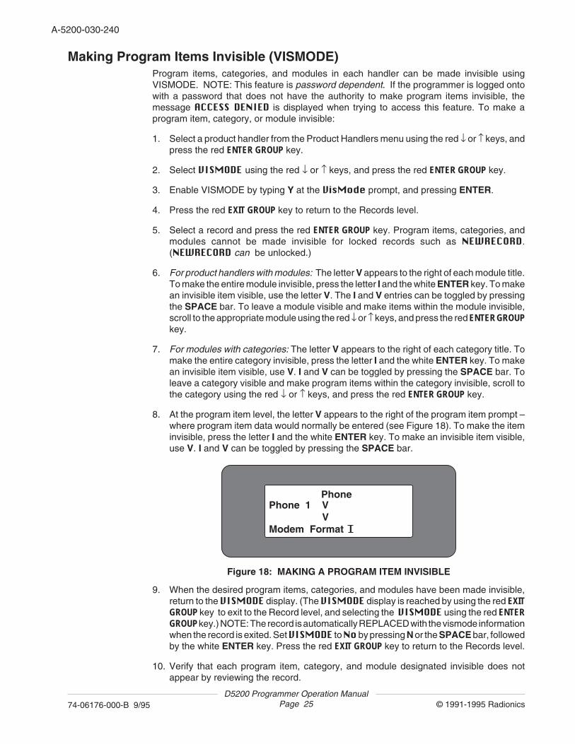
8. At the program item level, the letter V appears to the right of the program item prompt –where program item data would normally be entered (see Figure 18). To make the iteminvisible, press the letter I and the white ENTER key. To make an invisible item visible,use V. I and V can be toggled by pressing the SPACE bar.
9. When the desired program items, categories, and modules have been made invisible,return to the VISMODE display. (The VISMODE display is reached by using the red EXITGROUP key to exit to the Record level, and selecting the VISMODE using the red ENTERGROUP key.) NOTE: The record is automatically REPLACED with the vismode informationwhen the record is exited. Set VISMODE to No by pressing N or the SPACE bar, followedby the white ENTER key. Press the red EXIT GROUP key to return to the Records level.
10. Verify that each program item, category, and module designated invisible does notappear by reviewing the record.
PhonePhone 1 V Modem Format I V
Figure 18: MAKING A PROGRAM ITEM INVISIBLE
D5200 Programmer Operation ManualPage 26 © 1991-1995 Radionics74-06176-000-B 9/95
A-5200-030-260
Locking RecordsIndividual records can be locked, preventing data in the record from being edited. Lockedrecords are copied along with product handlers during programmer-to-programmer and disk-to-disk updates, making it easy to transfer custom records. Locked records, includingNEWRECORD, can be unlocked for custom programming. NOTE: This feature is passworddependent. If the programmer is logged onto with a password that does not have the authorityto lock records, the message ACCESS DENIED is displayed when trying to access thisfeature. To lock a record:
1. Scroll to the appropriate product handler from the Product Handlers menu using the red↓ or ↑ keys, and press the red ENTER GROUP key.
2. Scroll to LOCKRECORD using the red ↓ or ↑ keys, and press the red ENTER GROUP key.
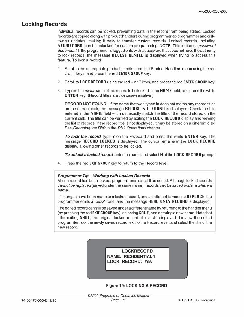
3. Type in the exact name of the record to be locked in the NAME field, and press the whiteENTER key. (Record titles are not case-sensitive.)
RECORD NOT FOUND: If the name that was typed in does not match any record titleson the current disk, the message RECORD NOT FOUND is displayed. Check the titleentered in the NAME field – it must exactly match the title of the record stored on thecurrent disk. The title can be verified by exiting the LOCK RECORD display and viewingthe list of records. If the record title is not displayed, it may be stored on a different disk.See Changing the Disk in the Disk Operations chapter.
To lock the record, type Y on the keyboard and press the white ENTER key. Themessage RECORD LOCKED is displayed. The cursor remains in the LOCK RECORDdisplay, allowing other records to be locked.
To unlock a locked record, enter the name and select N at the LOCK RECORD prompt.
4. Press the red EXIT GROUP key to return to the Record level.
Programmer Tip – Working with Locked RecordsAfter a record has been locked, program items can still be edited. Although locked recordscannot be replaced (saved under the same name), records can be saved under a differentname.
If changes have been made to a locked record, and an attempt is made to REPLACE, theprogrammer emits a "buzz" tone, and the message READ ONLY RECORD is displayed.
The edited record can still be saved under a different name by returning to the handler menu(by pressing the red EXIT GROUP key), selecting SAVE, and entering a new name. Note thatafter exiting SAVE, the original locked record title is still displayed. To view the editedprogram items of the newly saved record, exit to the Record level, and select the title of thenew record.
Figure 19: LOCKING A RECORD
LOCKRECORDNAME: RESIDENTIAL4LOCK RECORD: Yes
A-5200-030-260
© 1991-1995 Radionics74-06176-000-B 9/95D5200 Programmer Operation Manual
Page 27
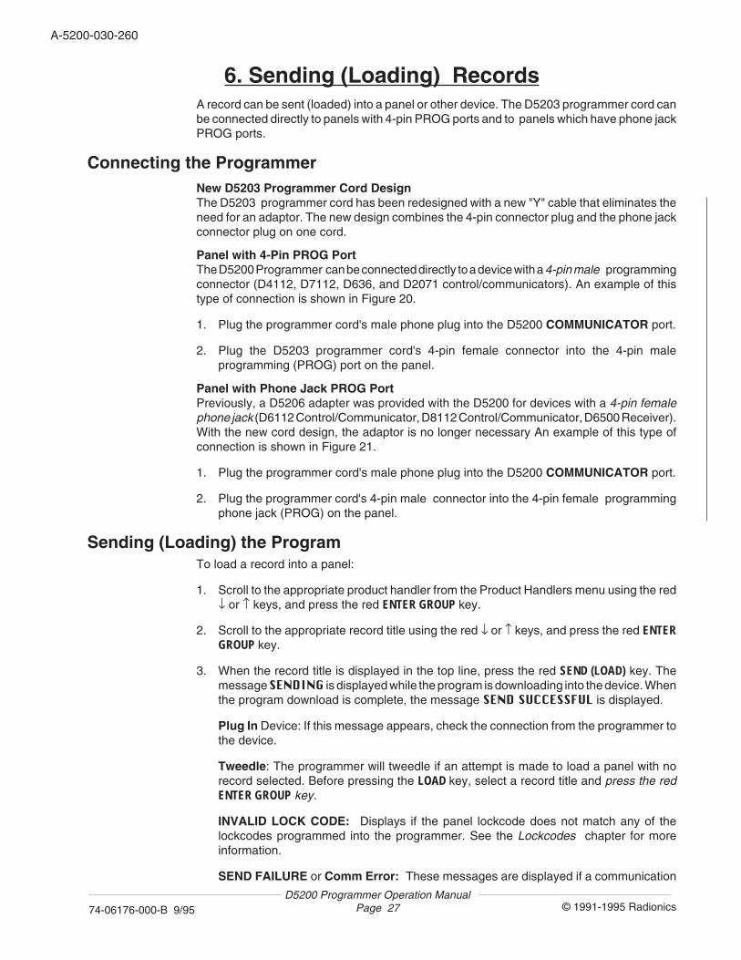
6. Sending (Loading) RecordsA record can be sent (loaded) into a panel or other device. The D5203 programmer cord canbe connected directly to panels with 4-pin PROG ports and to panels which have phone jackPROG ports.
Connecting the ProgrammerNew D5203 Programmer Cord DesignThe D5203 programmer cord has been redesigned with a new "Y" cable that eliminates theneed for an adaptor. The new design combines the 4-pin connector plug and the phone jackconnector plug on one cord.
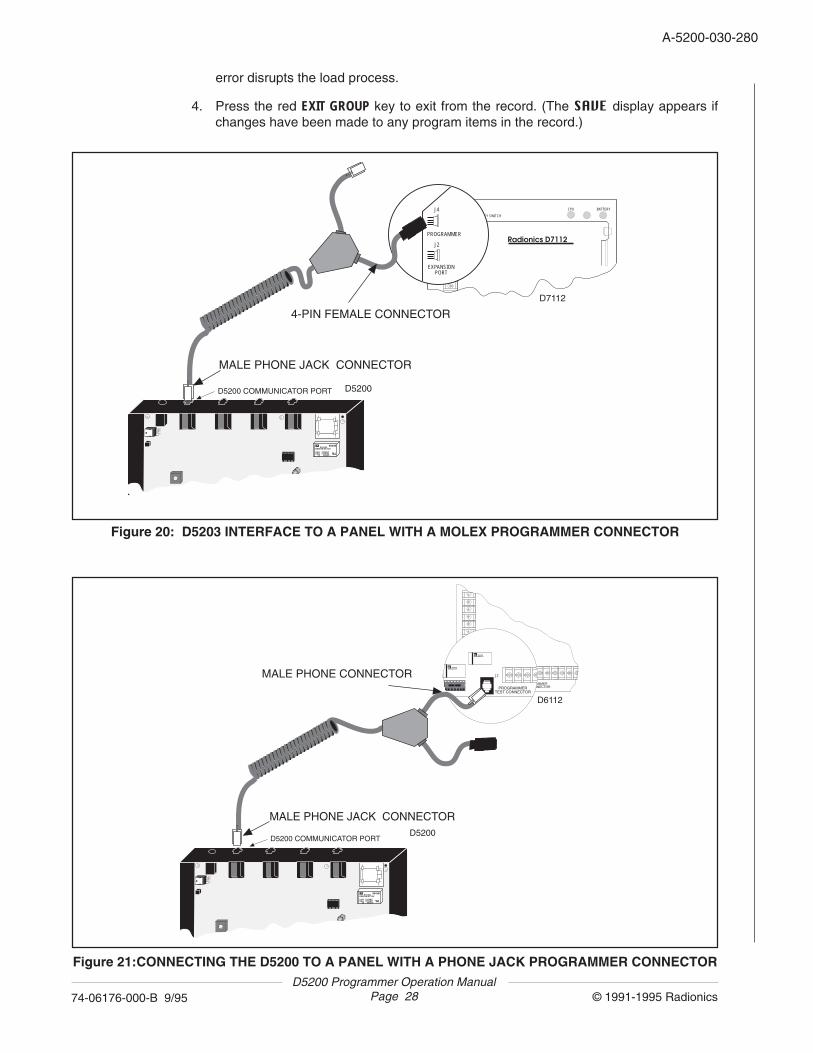
Panel with 4-Pin PROG PortThe D5200 Programmer can be connected directly to a device with a 4-pin male programmingconnector (D4112, D7112, D636, and D2071 control/communicators). An example of thistype of connection is shown in Figure 20.
1. Plug the programmer cord's male phone plug into the D5200 COMMUNICATOR port.
2. Plug the D5203 programmer cord's 4-pin female connector into the 4-pin maleprogramming (PROG) port on the panel.
Panel with Phone Jack PROG PortPreviously, a D5206 adapter was provided with the D5200 for devices with a 4-pin femalephone jack (D6112 Control/Communicator, D8112 Control/Communicator, D6500 Receiver).With the new cord design, the adaptor is no longer necessary An example of this type ofconnection is shown in Figure 21.
1. Plug the programmer cord's male phone plug into the D5200 COMMUNICATOR port.
2. Plug the programmer cord's 4-pin male connector into the 4-pin female programmingphone jack (PROG) on the panel.
Sending (Loading) the ProgramTo load a record into a panel:
1. Scroll to the appropriate product handler from the Product Handlers menu using the red↓ or ↑ keys, and press the red ENTER GROUP key.
2. Scroll to the appropriate record title using the red ↓ or ↑ keys, and press the red ENTERGROUP key.
3. When the record title is displayed in the top line, press the red SEND (LOAD) key. Themessage SENDING is displayed while the program is downloading into the device. Whenthe program download is complete, the message SEND SUCCESSFUL is displayed.
Plug In Device: If this message appears, check the connection from the programmer tothe device.
Tweedle: The programmer will tweedle if an attempt is made to load a panel with norecord selected. Before pressing the LOAD key, select a record title and press the redENTER GROUP key.
INVALID LOCK CODE: Displays if the panel lockcode does not match any of thelockcodes programmed into the programmer. See the Lockcodes chapter for moreinformation.
SEND FAILURE or Comm Error: These messages are displayed if a communication
D5200 Programmer Operation ManualPage 28 © 1991-1995 Radionics74-06176-000-B 9/95
A-5200-030-280
J2
PROGRAMMERTEST CONNECTOR
M AromatDS2E-M-DC12V
M AromatDS2E-M-DC12V
J2
PROGRAMMERTEST CONNECTOR
M AromatDS2E-M-DC12V
M AromatDS2E-M-DC12V
D6112
D5200
AromatDS2E-M-DC12V
0.6A 125VAC0.6A 110VDC 2Z 30VDC
8843B
W
SU
MALE PHONE JACK CONNECTOR
MALE PHONE CONNECTOR
D5200 COMMUNICATOR PORT
error disrupts the load process.
4. Press the red EXIT GROUP key to exit from the record. (The SAVE display appears ifchanges have been made to any program items in the record.)
Figure 20: D5203 INTERFACE TO A PANEL WITH A MOLEX PROGRAMMER CONNECTOR
Figure 21:CONNECTING THE D5200 TO A PANEL WITH A PHONE JACK PROGRAMMER CONNECTOR
CPU BATTERY
J1
J2
KEY SWITCH
EXPANSIONPORT
Radionics D7112
J4
PROGRAMMER
J4
PROGRAMMER
J2
EXPANSIONPORT
D7112
D5200
AromatDS2E-M-DC12V
0.6A 125VAC0.6A 110VDC 2Z 30VDC
8843B
W
SU
MALE PHONE JACK CONNECTOR
4-PIN FEMALE CONNECTOR
D5200 COMMUNICATOR PORT
A-5200-030-280
© 1991-1995 Radionics74-06176-000-B 9/95D5200 Programmer Operation Manual
Page 29
7. Receiving (Copying) RecordsA record can be copied from a control/communicator or other device into the D5200Programmer. The D5203 programmer cord can be connected directly to panels with 4-pinPROG ports and phone jack PROG ports.
Connecting the ProgrammerPanel with 4-Pin PROG PortThe D5200 Programmer can be connected directly to a device with a 4-pin male programmingconnector (D4112, D7112, D636, and D2071 control/communicators) as shown in Figure 20.
1. Plug the programmer cord's male phone plug into the D5200 COMMUNICATOR port.
2. Plug the programmer cord's 4-pin female connector into the 4-pin male programming(PROG) port on the panel.
Panel with Phone Jack PROG PortA D5206 adapter is no longer necessary with the D5200 for devices with a 4-pin female phonejack (D6112 Control/Communicator, D8112 Control/Communicator, D6500 Receiver). Thenew D5203 cord has a phone jack connection. An example of this type of connection is shownin Figure 21.
1. Plug the programmer cord's male phone plug into the D5200 COMMUNICATOR port.
2. Plug the programmer cord's 4-pin female connector into the panel programming phonejack (PROG).
Receiving (Copying) the Program
To copy a record from a panel into the programmer:
1. Scroll to the appropriate product handler from the Product Handlers menu using the red↓ or ↑ keys, and press the red ENTER GROUP key.
2. Place the flashing cursor on a record title (or NEWRECORD). This is the record to whichthe panel program will be copied. Press the red RECV (COPY) key. The messageRECEIVING is displayed while the record is uploading from the panel into the programmer.When the record copy is complete, the message RECEIVE SUCCESSFUL is displayed.
Plug In Device: If this message appears, check the connection from the programmer tothe device, and verify that the handler of the record selected is appropriate for the deviceto which the programmer is connected.
Tweedle: The programmer tweedles if an attempt is made to copy a program with norecord title (or NEWRECORD) selected by the flashing cursor.
INVALID LOCK CODE: Displays if the panel lockcode does not match any of thelockcodes in the programmer. See the Lockcodes chapter for more information.
RECEIVE FAILURE or Comm Error: These messages are displayed if a communi-cation error disrupts the copy process.
3. After a successful copy, the copied record is automatically entered, and module,category, or program item titles are displayed. The copied record can be saved under adifferent name, or replace the current record (see the Editing a Record section in theProgramming Records chapter).
D5200 Programmer Operation ManualPage 30 © 1991-1995 Radionics74-06176-000-B 9/95
A-5200-030-300
8. PasswordsAccess to several functions of the D5200 can be limited through the use of passwords. Eightpasswords can be programmed in the D5200. The D5200 Programmer is shipped with nopasswords initially entered. NOTE: This feature is password dependent. If the programmeris logged onto with a password that does not have the authority to edit passwords, themessage ACCESS DENIED is displayed when trying to access this feature.
If you forget all of the programmed passwords in your D5200, the programmer mustbe returned to Radionics (with an RMA number) for reinitialization. Please state onthe RMA that you are locked out of the programmer. All data on Disk A (the internalbattery backed RAM) is erased when the programmer is reinitialized.
To program passwords and designate authority to use certain functions of the D5200:
1. Scroll to SECURITY in the Product Handlers menu using the red ↓ or ↑ keys, and pressthe red ENTER GROUP key.
2. Scroll to Passwords in the SECURITY menu using the red ↓ or ↑ keys, and press thered ENTER GROUP key. The Passwords menu is displayed.
U1Password: Enter up to 8 characters for the User 1 password, and press the whiteENTER key. The User 1 password is automatically provided access to all D5200functions, and must be programmed before additional passwords (for User# 2 through8) can be programmed.
User#: The remaining fields are indexed programming fields. Enter the user number (2through 8 – the default for the first round of programming is 2), and press the whiteENTER key. The # in the U#Password field changes to match the number programmedin the User# field.
U#Password: The # in this field name changes to the number programmed in the User#field. (The default is U22222Password for the first round of programming.) Enter up to 8characters for the User # password, and press the white ENTER key.
In the following program items, typing Y and pressing the white ENTER key enables thefunction for the U#Password. An entry of N disables the function for the U#Password.Pressing the SPACE bar toggles between Y and N.
U#PasswordEnable: Enter Y to enable the U#Password. Enter N to disable theU#Password. If this program item is set to N, entering this password will not be acceptedas valid on programmer power-up.
U#Delete Record: Enter Y to give U#Password the authority to delete records. Enter Nto disable this function for U#Password.
U#Delete Handler: Enter Y to give U#Password the authority to delete handlers. EnterN to disable this function for U#Password.
U#Edit Lockcodes: Enter Y to give U#Password the authority to change panellockcodes. Enter N to disable this function for U#Password.
U#Edit Passwords: Enter Y to give U#Password the authority to change passwords.Enter N to disable this function for U#Password.
U#Edit Vis/Invis: Enter Y to give U#Password the authority to make program itemsinvisible. Enter N to disable this function for U#Password.
A-5200-030-300
© 1991-1995 Radionics74-06176-000-B 9/95D5200 Programmer Operation Manual
Page 31
U#Update Handler: Enter Y to give U#Password the authority to update handlers. EnterN to disable this function for U#Password.
U#Replace Record: Enter Y to give U#Password the authority to permanently change(replace) programmed account records. Enter N to disable this function for U#Password.NOTE: If this function is disabled for the Password, the user will still be able to editrecords, but edited records must be saved under a different name.
U#Format Disk: Enter Y to give U#Password the authority to format disks. Enter N todisable this function for U#Password. NOTE: Formatting a disk permanently erases alldata on the disk.
U#Lock Record: Enter Y to give U#Password the authority to lock records. Enter N todisable this function for U#Password.
3. After an entry is made for U#Lock Record, the display wraps around to U1Password.Press the white ENTER key or the red ↓ key to move the cursor to the User# field. Entera new user number and press the white ENTER key. The # in all U# program item titleschanges to match the new number programmed in the User# field. Passwords for upto 8 users are programmed as described in Step 2. (U1Password needs to beprogrammed only once, even though it scrolls into view after other U# passwordparameters have been programmed. Simply scroll past it with the red ↓ key .)
4. To exit the Passwords menu, press the red EXIT GROUP key. The cursor returns to theSECURITY menu.
5. To exit the SECURITY menu, press the red EXIT GROUP key. The cursor returns to theProduct Handlers level.
If a user attempts to access a function to which the user's password has not been givenauthority, the message ACCESS DENIED is displayed.
D5200 Programmer Operation ManualPage 32 © 1991-1995 Radionics74-06176-000-B 9/95
A-5200-030-320
9. LockCodesThe DataLock system uses lockcodes to lock panels from programming by unauthorizedprogrammers. A Datalocked panel has a lockcode in memory that the 5200 must match toone of the lockcodes in the 5200 lockcode records before the programming session cancontinue. The 5200 can not match the lockcode in the panel, the programming session isterminated.
Ram II organizes its lockcodes into four different types, default, primary, alternate, andunaltered. See LockCode Types below.
NOTE: This feature is password dependent. If the programmer is logged onto with apassword that does not have the authority to edit lockcodes, the message ACCESS DENIEDis displayed when trying to access this feature.
1. Scroll to SECURITY in the Product Handlers menu using the red ↓ or ↑ keys, and pressthe red ENTER GROUP key.
2. Use the red ↓ key to scroll down to LockCodes, and press the red ENTER GROUP key.
3. The cursor flashes in the Primary Lock data entry field. Enter a primary lockcode (from1 to 65535) and press the white ENTER key. NOTE: Due to an internal security algorithm,one of 255 lockcodes can result from an entry for the D4112 and D6112 control/communicators.
4. The cursor flashes in the Lock# data entry field. Enter the number of the lockcode youwish to program (from 1 to 50) and press the white ENTER key.
5. The cursor flashes in the Lockcode data entry field. This program item is indexed to theLock# entry. The number entered in Lock# will be added to the Lockcode prompt.For example, if 2 is entered for Lock, the next prompt will be Lockcode2. Enter alockcode (from 1 to 65535) and press the white ENTER key. NOTE: Due to an internalsecurity algorithm, one of 255 lockcodes can result from an entry for the D4112 andD6112 control/communicators.
6. The cursor flashes in the Primary Lock data entry field, which has wrapped around inthe display. Use the red ↓ key to scroll down to the Lock# prompt.
7. Enter the number of the new lockcode you wish to program and press the ENTER key.
8. The cursor flashes in the Lockcode data entry field. Enter a lockcode (from 1 to 65535)and press the white ENTER key.
9. Repeat steps 6 through 8 until all desired lockcodes have been programmed. To returnto the SECURITY menu, press the red EXIT GROUP key. To return to the Product Handlerslevel, press the red EXIT GROUP key again.
Programmer Tips – Working with Lockcodes
For panels with the datalock feature, the panel lockcode is verified when the panel isaccessed (record send or receive). There are four types of lockcodes:
• Default Lockcode: The code 12345 is the default entry for all D5200 lockcodes.
• Primary Lockcode: This is the lockcode programmed in the Primary Lock field.
• Alternate Lockcode: If the lockcode in a panel matches one of the first 35 "alternate"lockcodes (Lockcodes 1 through 35), the panel lockcode is changed to the primarylockcode, and the message LOCK CODE SET is displayed.
• Unaltered Lockcode: If the panel lockcode matches one of the remaining lockcodes(36 through 50), the panel lockcode is not changed.
If the panel lockcode does not match any of the programmer lockcodes, the messageINVALID LOCK CODE is displayed, and the panel cannot be accessed.
A-5200-030-320
© 1991-1995 Radionics74-06176-000-B 9/95D5200 Programmer Operation Manual
Page 33
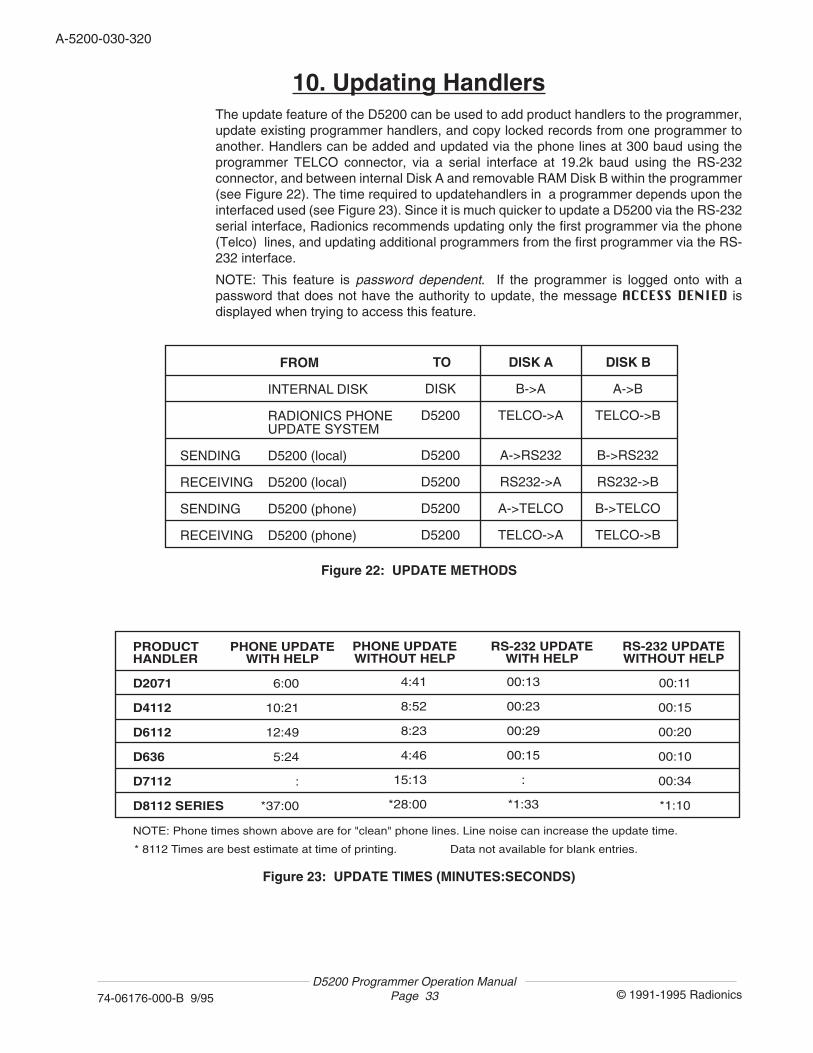
10. Updating HandlersThe update feature of the D5200 can be used to add product handlers to the programmer,update existing programmer handlers, and copy locked records from one programmer toanother. Handlers can be added and updated via the phone lines at 300 baud using theprogrammer TELCO connector, via a serial interface at 19.2k baud using the RS-232connector, and between internal Disk A and removable RAM Disk B within the programmer(see Figure 22). The time required to updatehandlers in a programmer depends upon theinterfaced used (see Figure 23). Since it is much quicker to update a D5200 via the RS-232serial interface, Radionics recommends updating only the first programmer via the phone(Telco) lines, and updating additional programmers from the first programmer via the RS-232 interface.
NOTE: This feature is password dependent. If the programmer is logged onto with apassword that does not have the authority to update, the message ACCESS DENIED isdisplayed when trying to access this feature.
PRODUCTHANDLER
D2071
D4112
D6112
D636
D7112
D8112 SERIES
6:00
10:21
12:49
5:24
:
*37:00
PHONE UPDATEWITH HELP
00:13
00:23
00:29
00:15
:
*1:33
RS-232 UPDATEWITH HELP
PHONE UPDATEWITHOUT HELP
RS-232 UPDATEWITHOUT HELP
4:41
8:52
8:23
4:46
15:13
*28:00
00:11
00:15
00:20
00:10
00:34
*1:10
NOTE: Phone times shown above are for "clean" phone lines. Line noise can increase the update time.
* 8112 Times are best estimate at time of printing. Data not available for blank entries.
Figure 22: UPDATE METHODS
SENDING
RECEIVING
SENDING
RECEIVING
INTERNAL DISK
RADIONICS PHONEUPDATE SYSTEM
D5200 (local)
D5200 (local)
D5200 (phone)
D5200 (phone)
FROM
DISK
D5200
D5200
D5200
D5200
D5200
DISK ATO DISK B
B->A
TELCO->A
A->RS232
RS232->A
A->TELCO
TELCO->A
A->B
TELCO->B
B->RS232
RS232->B
B->TELCO
TELCO->B
Figure 23: UPDATE TIMES (MINUTES:SECONDS)
D5200 Programmer Operation ManualPage 34 © 1991-1995 Radionics74-06176-000-B 9/95
A-5200-030-340
Disk to Disk UpdatesHandlers and locked records can be copied from Disk A to Disk B (and Disk B to Disk A) inthe programmer. If the "receiving" disk already has the handler to be updated, the "sending"disk transfers only its locked records (i.e. NEWRECORD) to the "receiving" disk. If the"receiving" disk does not currently contain the handler to be transferred, the "sending" disktransfers the handler and all locked records (i.e. NEWRECORD) to the "receiving" disk.
1. Scroll to UPDATE in the Product Handlers menu using the red ↓ or ↑ keys, and press thered ENTER GROUP key.
2. Type the handler name (i.e. 7112) at the Handler prompt, and press the white ENTERkey. The cursor moves down to the Include Help prompt.
3. The Include Help entry defaults to No. To include the handler help file in the update,press the SPACE bar to toggle the entry to Yes. Press the white ENTER key. The cursormoves down to the Phone prompt.
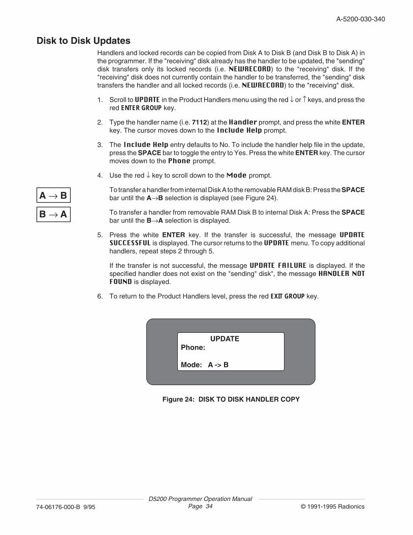
4. Use the red ↓ key to scroll down to the Mode prompt.
To transfer a handler from internal Disk A to the removable RAM disk B: Press the SPACEbar until the A→B selection is displayed (see Figure 24).
To transfer a handler from removable RAM Disk B to internal Disk A: Press the SPACEbar until the B→A selection is displayed.
5. Press the white ENTER key. If the transfer is successful, the message UPDATESUCCESSFUL is displayed. The cursor returns to the UPDATE menu. To copy additionalhandlers, repeat steps 2 through 5.
If the transfer is not successful, the message UPDATE FAILURE is displayed. If thespecified handler does not exist on the "sending" disk", the message HANDLER NOTFOUND is displayed.
6. To return to the Product Handlers level, press the red EXIT GROUP key.
A → B
B → A
Figure 24: DISK TO DISK HANDLER COPY
UPDATEPhone: Mode: A -> B

A-5200-030-340
© 1991-1995 Radionics74-06176-000-B 9/95D5200 Programmer Operation Manual
Page 35
Updating using the Radionics Update System via the PhoneThe programmer can be set up to receive handler updates from the Radionics Update Systemvia the phone (pulse dialing only). If the programmer already has the handler to be updated,the Update System transfers only its locked records (i.e. NEWRECORD) to the programmer.If the programmer does not currently contain the handler to be transferred, the UpdateSystem transfers the handler and all locked records (i.e. NEWRECORD) to the programmer.Connect the programmer to the phone line (TELCO port to phone jack) as shown in Figure25, and set up the programmer as shown below.
1. Scroll to UPDATE in the Product Handlers menu using the red ↓ or ↑ keys, and press thered ENTER GROUP key.
2. Type the handler name (i.e. 7112) at the Handler prompt, and press the white ENTERkey. The cursor moves down to the Include Help prompt.
3. The Include Help entry defaults to No. To include the handler help file in the update,press the SPACE bar to toggle the entry to Yes. Press the white ENTER key. The cursormoves down to the Phone prompt.
4. Enter the phone number of the Radionics Update System, 14087577832, in the Phonefield. (Add or remove prefix information as required for dialing from your area.) Press thewhite ENTER key. The cursor moves down to the Mode prompt.
Figure 25: CONNECTING TO THE RADIONICS UPDATE SYSTEM
EXTERNALPOWER
COMMUNICATOR AUXILIARY RS-232 TELCOD5200
PROGRAMMER
UPDATEPhone: 14087577832 Mode: TELCO -> A
PHONE NETWORK RADIONICSUPDATESYSTEM
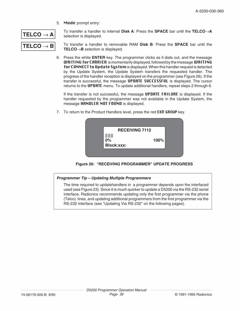
D5200 Programmer Operation ManualPage 36 © 1991-1995 Radionics74-06176-000-B 9/95
A-5200-030-360
5. Mode prompt entry:
To transfer a handler to internal Disk A: Press the SPACE bar until the TELCO→Aselection is displayed.
To transfer a handler to removable RAM Disk B: Press the SPACE bar until theTELCO→B selection is displayed.
6. Press the white ENTER key. The programmer clicks as it dials out, and the messageWAITING for CARRIER is momentarily displayed, followed by the message WAITINGfor CONNECT to Update System is displayed. When this handler request is detectedby the Update System, the Update System transfers the requested handler. Theprogress of the handler reception is displayed on the programmer (see Figure 26). If thetransfer is successful, the message UPDATE SUCCESSFUL is displayed. The cursorreturns to the UPDATE menu. To update additional handlers, repeat steps 2 through 6.
If the transfer is not successful, the message UPDATE FAILURE is displayed. If thehandler requested by the programmer was not available in the Update System, themessage HANDLER NOT FOUND is displayed.
7. To return to the Product Handlers level, press the red EXIT GROUP key.
RECEIVING 7112 0% 100%Block:xxx:
Figure 26: "RECEIVING PROGRAMMER" UPDATE PROGRESS
Programmer Tip – Updating Multiple Programmers
The time required to updatehandlers in a programmer depends upon the interfacedused (see Figure 23). Since it is much quicker to update a D5200 via the RS-232 serialinterface, Radionics recommends updating only the first programmer via the phone(Telco) lines, and updating additional programmers from the first programmer via theRS-232 interface (see "Updating Via RS-232" on the following pages).
TELCO → A
TELCO → B
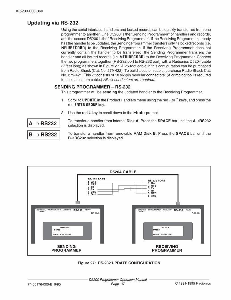
A-5200-030-360
© 1991-1995 Radionics74-06176-000-B 9/95D5200 Programmer Operation Manual
Page 37
Updating via RS-232Using the serial interface, handlers and locked records can be quickly transferred from oneprogrammer to another. One D5200 is the "Sending Programmer" of handlers and records,and the second D5200 is the "Receiving Programmer". If the Receiving Programmer alreadyhas the handler to be updated, the Sending Programmer transfers only its locked records (i.e.NEWRECORD) to the Receiving Programmer. If the Receiving Programmer does notcurrently contain the handler to be transferred, the Sending Programmer transfers thehandler and all locked records (i.e. NEWRECORD) to the Receiving Programmer. Connectthe two programmers together (RS-232 port to RS-232 port) with a Radionics D5204 cable(2 feet long) as shown in Figure 27. A 25-foot cable in this configuration can be purchasedfrom Radio Shack (Cat. No. 279-422). To build a custom cable, purchase Radio Shack Cat.No. 279-421. This kit consists of 10 six-pin modular connectors. (A crimping tool is requiredto build a custom cable.) All six conductors are required.
SENDING PROGRAMMER – RS-232This programmer will be sending the updated handler to the Receiving Programmer.
1. Scroll to UPDATE in the Product Handlers menu using the red ↓ or ↑ keys, and press thered ENTER GROUP key.
2. Use the red ↓ key to scroll down to the Mode prompt.
To transfer a handler from internal Disk A: Press the SPACE bar until the A→RS232selection is displayed.
To transfer a handler from removable RAM Disk B: Press the SPACE bar until theB→RS232 selection is displayed.
EXTERNALPOWER
COMMUNICATOR AUXILIARY RS-232 TELCO
D5200
RECEIVING PROGRAMMER
UPDATEPhone: Mode: RS232 -> A
EXTERNALPOWER
COMMUNICATOR AUXILIARY RS-232 TELCO
D5200
SENDING PROGRAMMER
D5204 CABLE
RS-232 PORT1 Gnd2 RTS3 Tx4 Rx5 CTS6 Gnd
RS-232 PORT1 Gnd2 RTS3 Tx4 Rx5 CTS6 Gnd
UPDATEPhone: Mode: A -> RS232
Figure 27: RS-232 UPDATE CONFIGURATION
A → RS232
B → RS232
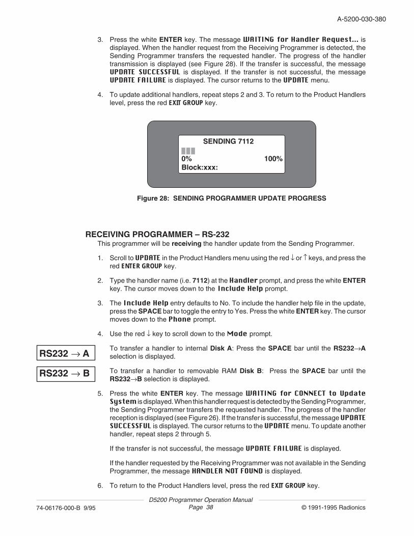
D5200 Programmer Operation ManualPage 38 © 1991-1995 Radionics74-06176-000-B 9/95
A-5200-030-380
3. Press the white ENTER key. The message WAITING for Handler Request... isdisplayed. When the handler request from the Receiving Programmer is detected, theSending Programmer transfers the requested handler. The progress of the handlertransmission is displayed (see Figure 28). If the transfer is successful, the messageUPDATE SUCCESSFUL is displayed. If the transfer is not successful, the messageUPDATE FAILURE is displayed. The cursor returns to the UPDATE menu.
4. To update additional handlers, repeat steps 2 and 3. To return to the Product Handlerslevel, press the red EXIT GROUP key.
SENDING 7112 0% 100%Block:xxx:
Figure 28: SENDING PROGRAMMER UPDATE PROGRESS
RECEIVING PROGRAMMER – RS-232This programmer will be receiving the handler update from the Sending Programmer.
1. Scroll to UPDATE in the Product Handlers menu using the red ↓ or ↑ keys, and press thered ENTER GROUP key.
2. Type the handler name (i.e. 7112) at the Handler prompt, and press the white ENTERkey. The cursor moves down to the Include Help prompt.
3. The Include Help entry defaults to No. To include the handler help file in the update,press the SPACE bar to toggle the entry to Yes. Press the white ENTER key. The cursormoves down to the Phone prompt.
4. Use the red ↓ key to scroll down to the Mode prompt.
To transfer a handler to internal Disk A: Press the SPACE bar until the RS232→Aselection is displayed.
To transfer a handler to removable RAM Disk B: Press the SPACE bar until theRS232→B selection is displayed.
5. Press the white ENTER key. The message WAITING for CONNECT to UpdateSystem is displayed. When this handler request is detected by the Sending Programmer,the Sending Programmer transfers the requested handler. The progress of the handlerreception is displayed (see Figure 26). If the transfer is successful, the message UPDATESUCCESSFUL is displayed. The cursor returns to the UPDATE menu. To update anotherhandler, repeat steps 2 through 5.
If the transfer is not successful, the message UPDATE FAILURE is displayed.
If the handler requested by the Receiving Programmer was not available in the SendingProgrammer, the message HANDLER NOT FOUND is displayed.
6. To return to the Product Handlers level, press the red EXIT GROUP key.
RS232 → A
RS232 → B
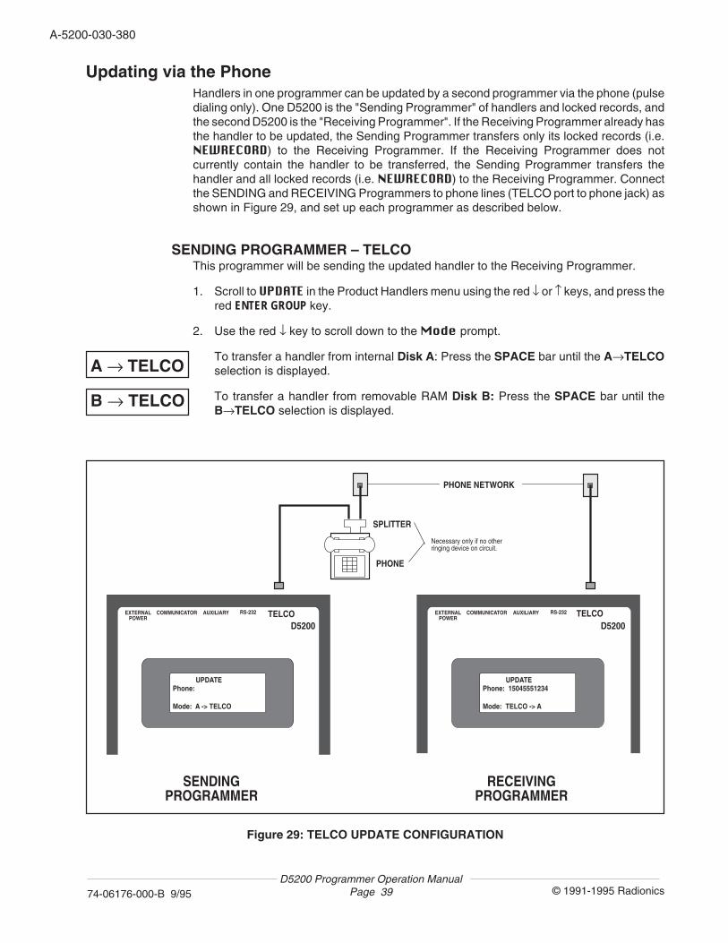
A-5200-030-380
© 1991-1995 Radionics74-06176-000-B 9/95D5200 Programmer Operation Manual
Page 39
Figure 29: TELCO UPDATE CONFIGURATION
Updating via the PhoneHandlers in one programmer can be updated by a second programmer via the phone (pulsedialing only). One D5200 is the "Sending Programmer" of handlers and locked records, andthe second D5200 is the "Receiving Programmer". If the Receiving Programmer already hasthe handler to be updated, the Sending Programmer transfers only its locked records (i.e.NEWRECORD) to the Receiving Programmer. If the Receiving Programmer does notcurrently contain the handler to be transferred, the Sending Programmer transfers thehandler and all locked records (i.e. NEWRECORD) to the Receiving Programmer. Connectthe SENDING and RECEIVING Programmers to phone lines (TELCO port to phone jack) asshown in Figure 29, and set up each programmer as described below.
SENDING PROGRAMMER – TELCOThis programmer will be sending the updated handler to the Receiving Programmer.
1. Scroll to UPDATE in the Product Handlers menu using the red ↓ or ↑ keys, and press thered ENTER GROUP key.
2. Use the red ↓ key to scroll down to the Mode prompt.
To transfer a handler from internal Disk A: Press the SPACE bar until the A→TELCOselection is displayed.
To transfer a handler from removable RAM Disk B: Press the SPACE bar until theB→TELCO selection is displayed.
A → TELCO
B → TELCO
EXTERNALPOWER
COMMUNICATOR AUXILIARY RS-232 TELCOD5200
RECEIVING PROGRAMMER
UPDATEPhone: 15045551234 Mode: TELCO -> A
EXTERNALPOWER
COMMUNICATOR AUXILIARY RS-232 TELCOD5200
SENDING PROGRAMMER
PHONE NETWORK
PHONE
SPLITTER
UPDATEPhone: Mode: A -> TELCO
Necessary only if no other ringing device on circuit.
D5200 Programmer Operation ManualPage 40 © 1991-1995 Radionics74-06176-000-B 9/95
A-5200-030-400
3. Wait until the phone rings, and then press the white ENTER key. The messageWAITING for Handler Request... is displayed. When the handler request from theReceiving Programmer is detected, the Sending Programmer transfers the requestedhandler at 300 baud. The progress of the handler transmission is displayed (see Figure28). If the transfer is successful, the message UPDATE SUCCESSFUL is displayed. If thetransfer is not successful, the message UPDATE FAILURE is displayed. The cursorreturns to the UPDATE menu. To update additional handlers, repeat steps 2 and 3.
4. To return to the Product Handlers level, press the red EXIT GROUP key.
RECEIVING PROGRAMMER – TELCOThis programmer dials out and receives the handler update from the Sending Programmer.
1. Scroll to UPDATE in the Product Handlers menu using the red ↓ or ↑ keys, and press thered ENTER GROUP key.
2. Type the handler name (i.e. 7112) at the Handler prompt, and press the white ENTERkey. The cursor moves down to the Include Help prompt.
3. The Include Help entry defaults to No. To include the handler help file in the update,press the SPACE bar to toggle the entry to Yes. Press the white ENTER key. The cursormoves down to the Phone prompt.
4. Enter the phone number of the Sending Programmer in the Phone field. This entry canbe up to 24 characters: 0-9, C (3 second wait), D (7 second wait), and can wrap aroundto the second line under the Phone prompt. Press the white ENTER key. The cursormoves down to the Mode prompt.
5. Mode prompt entry:
To transfer a handler to internal Disk A: Press the SPACE bar until the TELCO→Aselection is displayed.
To transfer a handler to removable RAM Disk B: Press the SPACE bar until theTELCO→B selection is displayed.
6. Press the white ENTER key. The programmer clicks as it dials out, and the messageWAITING for CONNECT to Update System is displayed. When this handler requestis detected by the Sending Programmer, the Sending Programmer transfers therequested handler. The progress of the handler reception is displayed (see Figure 26).If the transfer is successful, the message UPDATE SUCCESSFUL is displayed. Thecursor returns to the UPDATE menu. To update additional handlers, repeat steps 2through 6.
If the transfer is not successful, the message UPDATE FAILURE is displayed. If thehandler requested by the Receiving Programmer was not available in the SendingProgrammer, the message HANDLER NOT FOUND is displayed.
7. To return to the Product Handlers level, press the red EXIT GROUP key.
TELCO → A
TELCO → B
A-5200-030-400
© 1991-1995 Radionics74-06176-000-B 9/95D5200 Programmer Operation Manual
Page 41
11. Deleting HandlersTo delete a handler from a disk on the programmer, follow the steps below. NOTE: Thisfeature is password dependent . If the programmer is logged onto with a password that doesnot have the authority to delete handlers, the message ACCESS DENIED is displayed whentrying to access this feature.
1. Scroll to DELETE in the Product Handlers menu using the red ↓ or ↑ keys, and press thered ENTER GROUP key.
2. Type the handler name (i.e. 7112) at the HandName prompt, and press the whiteENTER key. A warning message is displayed. To abort the handler delete process, typeN. To continue with the delete process, press Y. When the handler has been deleted, themessage HANDLER DELETED is displayed.
HANDLER NOT FOUND: If the name entered in the HandName field does not matchany handler titles on the current disk, the message HANDLER NOT FOUND is displayed.Check the title entered in the HandName field – it must exactly match the title of thehandler stored on the current disk. The title can be verified by exiting the DELETE displayand viewing the list of handlers. If the handler title is not displayed, it may be stored ona different disk. See Changing the Disk section in the Disk Operations chapter.
3. To delete a help file, use the red ↓ key to scroll down to the HelpName prompt.
4. Type the help file name, which is identical to the handler name (i.e. 7112) at theHelpName prompt, and press the white ENTER key. A warning message is displayed.To abort the help file delete process, type N. To continue with the delete process, pressY. When the help file has been deleted, the message HELP DELETED is displayed.
HELP NOT FOUND: If the name entered in the HelpName field does not match anyhandler titles on the current disk, the message HELP NOT FOUND is displayed. Checkthe title entered in the HelpName field – it must exactly match the title of the help filestored on the current disk. The title can be verified by exiting the DELETE display andviewing the list of handlers. If the handler title which is associated with the help file is notdisplayed, the handler and help file may be stored on a different disk. See Changing theDisk section in the Disk Operations chapter.
D5200 Programmer Operation ManualPage 42 © 1991-1995 Radionics74-06176-000-B 9/95
A-5200-030-420
5. To return to the Product Handlers level, press the red EXIT GROUP key.
12. Programmer Time OutThe D5200 Programmer is equipped with a power-saving timeout feature – the D5200automatically powers down if no keys have been pressed within a programmed amount oftime. Follow the steps below to program the timeout.
1. Scroll to SECURITY in the Product Handlers menu using the red ↓ or ↑ keys, and pressthe red ENTER GROUP key.
2. Scroll to Time Out in the SECURITY menu using the red ↓ or ↑ keys. Enter the desiredtimeout value (from 02 to 10 minutes) and press the white ENTER key.
3. To exit the SECURITY menu, press the red EXIT GROUP key. The cursor returns to theProduct Handlers level.
Records Open When TimeOut OccursOne minute before the D5200 goes into TimeOut power-down, the programmer emits a"buzz", and the message 59 SEC TO POWER DOWN is displayed. The programmer "countsdown" until the time programmed in Time Out has expired. If a record is still open when theD5200 Programmer goes into a power-down timeout, the record is saved under the titleTIMEOUTSAVE. One TIMEOUTSAVE record can be saved per handler. If a TIMEOUTSAVErecord already exists for a particular handler, the new TIMEOUTSAVE record will overwritethe old TIMEOUTSAVE record.
When the programmer is switched on and the handler is entered, the programmer emits a"buzz" tone, and the words SAVE TIMEOUT RECORD appear among the items in thedisplay. Press the red ↓ key to scroll to the TIMEOUTSAVE record. The TIMEOUTSAVErecord can be opened, saved under a different title, and deleted like other records (see Editinga Record, Copying a Record, and Deleting a Record in the Programming Records chapter).
A-5200-030-420
© 1991-1995 Radionics74-06176-000-B 9/95D5200 Programmer Operation Manual
Page 43
13. Help ScreensHelp screens can be accessed from almost all prompts displayed on the D5200. Help screensare also available for individual product handler program items. Product handler help screenscan be installed when updating the handler (see the Updating Handlers chapter).
Accessing Help Screens1. To view the help screen for a particular item, move the cursor to the item and press the
red HELP key.
If there is no help screen for a particular program item or prompt, or the help file for aparticular handler has not been loaded, the message NO HELP AVAILABLE isdisplayed.
2. The item is displayed in the top line, and the help screen is displayed below. Use the red↑ and ↓ keys to scroll through the help screen.
3. Data can be entered in program item help screen. When the white ENTER key is pressed,the cursor exits the help screen and flashes on the next program item.
4. The help screen can be exited by pressing the red HELP key. The red EXIT GROUP, ENTERGROUP, RECV, and SEND keys can also be used to exit help screens, provided thatpressing the particular key is an appropriate action for the item displayed in the helpscreen.
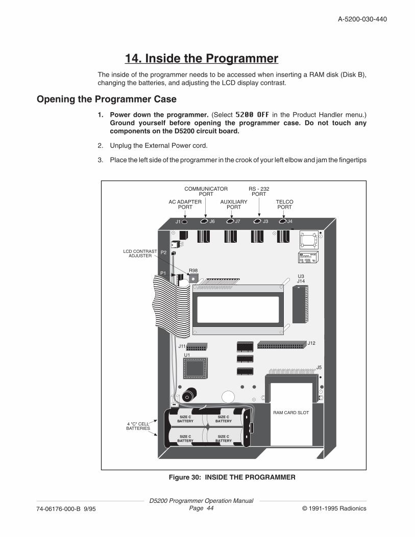
D5200 Programmer Operation ManualPage 44 © 1991-1995 Radionics74-06176-000-B 9/95
A-5200-030-440
14. Inside the ProgrammerThe inside of the programmer needs to be accessed when inserting a RAM disk (Disk B),changing the batteries, and adjusting the LCD display contrast.
Opening the Programmer Case
1. Power down the programmer. (Select 5200 OFF in the Product Handler menu.)Ground yourself before opening the programmer case. Do not touch anycomponents on the D5200 circuit board.
2. Unplug the External Power cord.
3. Place the left side of the programmer in the crook of your left elbow and jam the fingertips
Figure 30: INSIDE THE PROGRAMMER
SIZE CBATTERY
SIZE CBATTERY
SIZE CBATTERY
SIZE CBATTERY
AromatDS2E-M-DC12V
0.6A 125VAC0.6A 110VDC 2Z 30VDC
8843B
W
SU
J6 J7 J3 J4
U3J14
J12
J5
J11
U1
J1
P2
P1 R98
AC ADAPTERPORT
COMMUNICATORPORT
AUXILIARYPORT
RS - 232PORT
TELCOPORT
LCD CONTRAST ADJUSTER
4 "C" CELL BATTERIES
RAM CARD SLOT
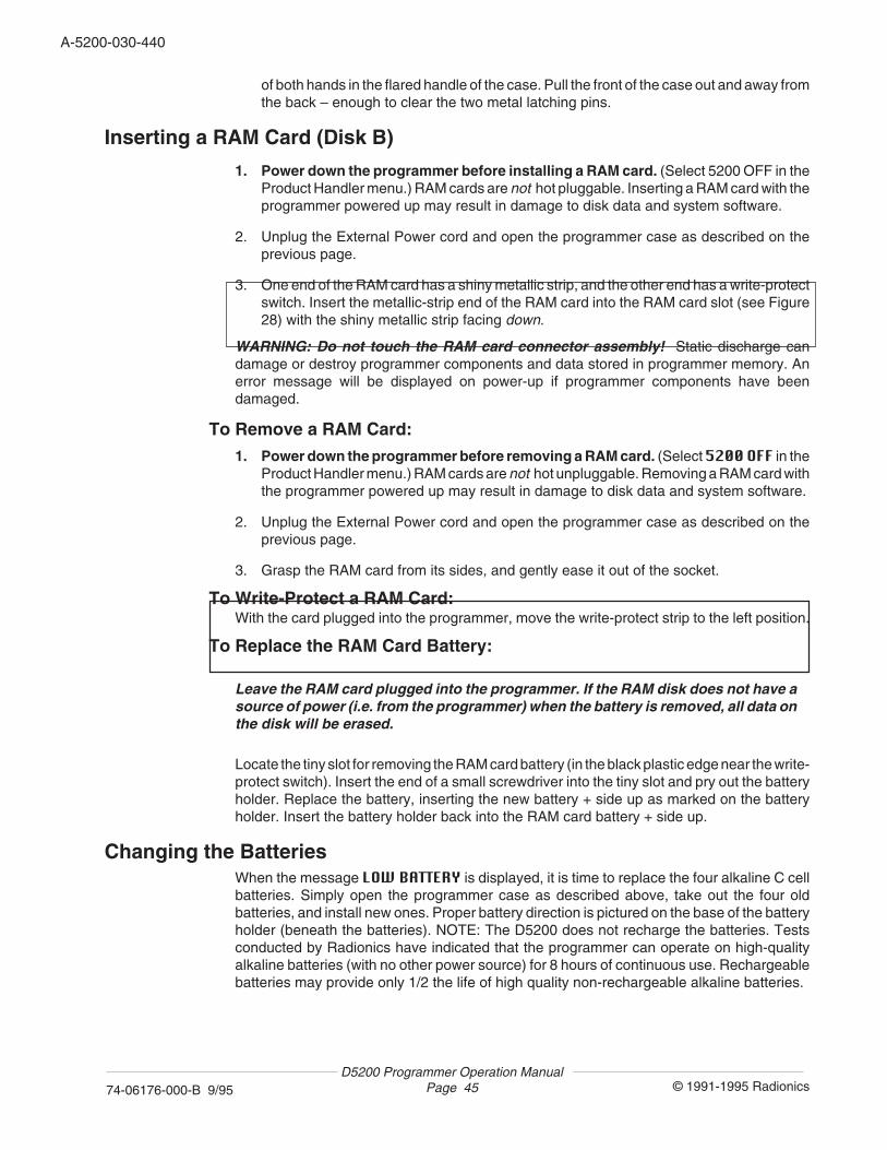
A-5200-030-440
© 1991-1995 Radionics74-06176-000-B 9/95D5200 Programmer Operation Manual
Page 45
of both hands in the flared handle of the case. Pull the front of the case out and away fromthe back – enough to clear the two metal latching pins.
Inserting a RAM Card (Disk B)
1. Power down the programmer before installing a RAM card. (Select 5200 OFF in theProduct Handler menu.) RAM cards are not hot pluggable. Inserting a RAM card with theprogrammer powered up may result in damage to disk data and system software.
2. Unplug the External Power cord and open the programmer case as described on theprevious page.
3. One end of the RAM card has a shiny metallic strip, and the other end has a write-protectswitch. Insert the metallic-strip end of the RAM card into the RAM card slot (see Figure28) with the shiny metallic strip facing down.
WARNING: Do not touch the RAM card connector assembly! Static discharge candamage or destroy programmer components and data stored in programmer memory. Anerror message will be displayed on power-up if programmer components have beendamaged.
To Remove a RAM Card:
1. Power down the programmer before removing a RAM card. (Select 5200 OFF in theProduct Handler menu.) RAM cards are not hot unpluggable. Removing a RAM card withthe programmer powered up may result in damage to disk data and system software.
2. Unplug the External Power cord and open the programmer case as described on theprevious page.
3. Grasp the RAM card from its sides, and gently ease it out of the socket.
To Write-Protect a RAM Card:With the card plugged into the programmer, move the write-protect strip to the left position.
To Replace the RAM Card Battery:
Leave the RAM card plugged into the programmer. If the RAM disk does not have asource of power (i.e. from the programmer) when the battery is removed, all data onthe disk will be erased.
Locate the tiny slot for removing the RAM card battery (in the black plastic edge near the write-protect switch). Insert the end of a small screwdriver into the tiny slot and pry out the batteryholder. Replace the battery, inserting the new battery + side up as marked on the batteryholder. Insert the battery holder back into the RAM card battery + side up.
Changing the BatteriesWhen the message LOW BATTERY is displayed, it is time to replace the four alkaline C cellbatteries. Simply open the programmer case as described above, take out the four oldbatteries, and install new ones. Proper battery direction is pictured on the base of the batteryholder (beneath the batteries). NOTE: The D5200 does not recharge the batteries. Testsconducted by Radionics have indicated that the programmer can operate on high-qualityalkaline batteries (with no other power source) for 8 hours of continuous use. Rechargeablebatteries may provide only 1/2 the life of high quality non-rechargeable alkaline batteries.
D5200 Programmer Operation ManualPage 46 © 1991-1995 Radionics74-06176-000-B 9/95
A-5200-030-460
Adjusting the LCD Display ContrastWith a small screwdriver, turn the LCD contrast screw clockwise to increase display contrast,or counterclockwise to decrease contrast. Test the contrast setting by holding down a repeatkey (i.e. scroll the display with the red ↓ key). If the contrast is set incorrectly, the display mayblur when scrolled quickly.
15. Troubleshooting Guide
This chapter contains a list of warning messages that can be displayed on the programmer,and general programmer problems.
Programmer ProblemsLCD Display Blank If the LCD display is blank, but the programmer is emitting normal operating
sounds (tweedle, pip, etc.), turn the LCD contrast adjuster located next to thedisplay on the inside of the programmer.
Warning Messages59 SEC TO POWER DOWN The D5200 automatically powers down if no keys have been pressed within the
time programmed in Time Out (SECURITY menu). To prevent the programmerfrom powering down, press any key (an arrow key is recommended, since itwill not change data or levels).
ACCESS DENIED The password used to log on to the programmer has not been given the authorityto access the function.
BAD DATABASE FILE This message is displayed if an attempt was made to copy a record to a disk thatdoes not contain the associated product handler.
LOW BATTERY This message is displayed approximately one hour prior to low-battery powerdown. This message is displayed every 10 minutes until shut down. When thismessage is displayed, save the record that is currently open, power-down theprogrammer, and replace the batteries. NOTE: Powering up a programmer witha low battery condition may drain the batteries in less than one hour, dependingupon the quality of the batteries.
**BAD SYSTEM FILE * This message is displayed when the D5200 system file has been damaged.Press any key to Press any key to configure the D5200 with a new system file. All passwordsdefault SYSTEM FILE and lockcodes are lost when a new system file is installed, and the programmer
can only be accessed with the default all blank password (simply press the whiteENTER key). Reprogram all passwords and lockcodes (SECURITY menu).NOTE: This message signifies an unusual event. If this message is displayed,consider returning the unit to Radionics for repair.
Comm Error Displayed if a communication error disrupts a send (load) or receive (copy)process.
DISK A (or B) BAD This message is displayed when the internal RAM disk (Disk A) or RAM CardFORMAT IMMEDIATELY (Disk B) has been damaged. Press any key to access the PRODUCT HANDLERSPress any key menu. Format the disk (FormatDisk in the SECURITY menu) as soon as
possible. NOTE: This message signifies an unusual event. If this message isdisplayed, consider returning the unit to Radionics for repair.
A-5200-030-460
© 1991-1995 Radionics74-06176-000-B 9/95D5200 Programmer Operation Manual
Page 47
HANDLER NOT FOUND This message is displayed if the handler requested by the Receiving Program-mer during an update was not available in the Sending Programmer, or thehandler was not found on the current disk when attempting to delete the handler.
HELP NOT FOUND This message is displayed if the help file requested by the Receiving Program-mer during an update was not available in the Sending Programmer, or the helpfile was not found on the current disk when attempting to delete the help file.
INVALID LOCK CODE This message is displayed if the panel lockcode does not match any of thelockcodes programmed into the programmer. See the Lockcodes chapter formore information.
NO HELP AVAILABLE There is no help screen for the particular program item or prompt selected, or thehelp file for a particular handler has not been loaded.
Plug In Device If this message appears during a send (load) or receive (copy), check theconnection from the programmer to the device. Verify that one end of theprogrammer cord is plugged into the D5200 Programmer cord, and the other endis plugged into the device (panel, etc.).
RAM CARD NOT PRESENT This message is displayed if Disk B was selected and the RAM card is notplugged into the programmer.
RAM DISK PROTECTED This message is displayed if Disk B was selected and the RAM card in theprogrammer is write-protected.
READ ONLY RECORD This message is displayed if the record you are trying to replace or delete islocked. Changes to a locked record can be saved only under a different name.
RECEIVE FAILURE This message is displayed if a communication error disrupts a copy process.
RECORD EXISTS This message is displayed if you are attempting to save a copied record undera name which has already been given to a record on the current disk. Type in adifferent title for the new file.
RECORD NOT DELETED This message is displayed if the record you are trying to delete is the last recordin the specific product handler database. The last record of each product handlercannot be deleted.
RECORD NOT FOUND The record name entered does not match any record titles on the current disk.The title must exactly match the title of a record stored on the current disk. If therecord title is not displayed, it may be stored on a different disk. See Changingthe Disk section in the Disk Operations chapter.
RECORD NOT REPLACED This message is displayed if the name entered in a REPLACE display does notmatch any record titles on the current disk. Check the title entered in the NAMEfield – it must exactly match the title of the record stored on the current disk.
SEND FAILURE This message is displayed if a communication error disrupts a load process.
UPDATE FAILURE This message is displayed if a handler transfer (RS-232 to RS-232 or TELCO toTELCO) is not successful.
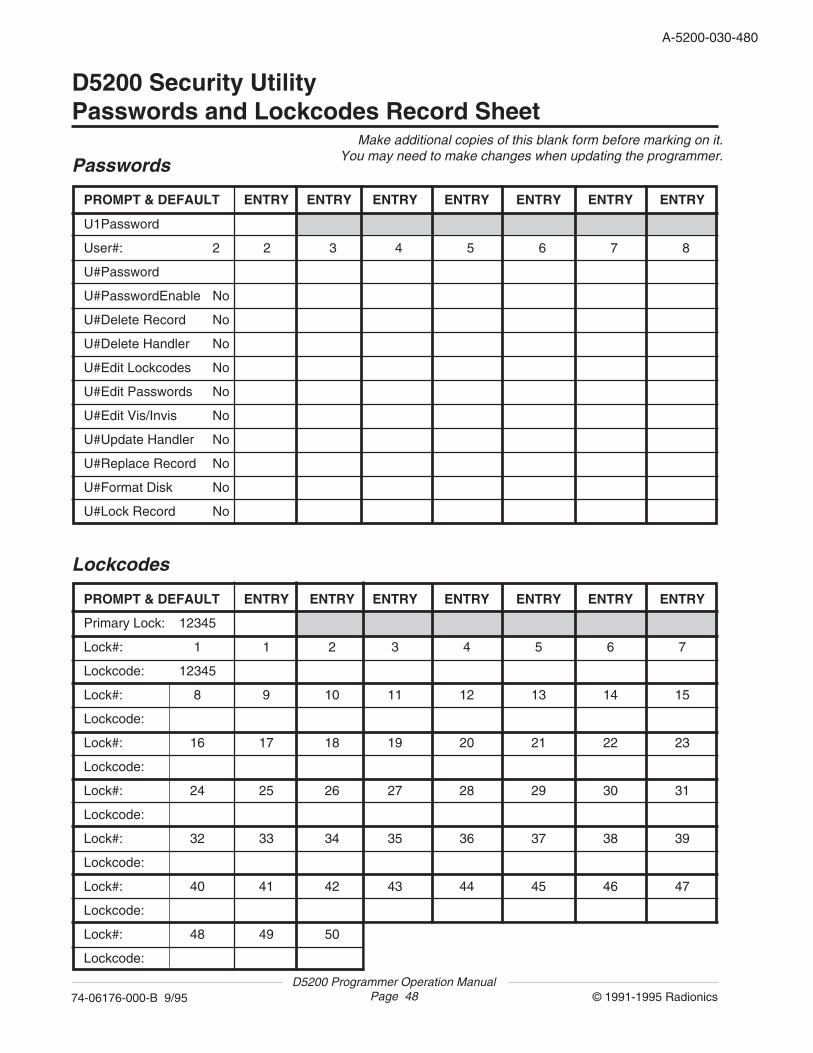
D5200 Programmer Operation ManualPage 48 © 1991-1995 Radionics74-06176-000-B 9/95
A-5200-030-480
D5200 Security UtilityPasswords and Lockcodes Record Sheet
PROMPT & DEFAULT ENTRY ENTRY ENTRY ENTRY ENTRY ENTRY ENTRY
Primary Lock: 12345
Lock#: 1 1 2 3 4 5 6 7
Lockcode: 12345
Lock#: 8 9 10 11 12 13 14 15
Lockcode:
Lock#: 16 17 18 19 20 21 22 23
Lockcode:
Lock#: 24 25 26 27 28 29 30 31
Lockcode:
Lock#: 32 33 34 35 36 37 38 39
Lockcode:
Lock#: 40 41 42 43 44 45 46 47
Lockcode:
Lock#: 48 49 50
Lockcode:
Lockcodes
U1Password
User#: 2 2 3 4 5 6 7 8
U#Password
U#PasswordEnable No
U#Delete Record No
U#Delete Handler No
U#Edit Lockcodes No
U#Edit Passwords No
U#Edit Vis/Invis No
U#Update Handler No
U#Replace Record No
U#Format Disk No
U#Lock Record No
PROMPT & DEFAULT ENTRY ENTRY ENTRY ENTRY ENTRY ENTRY ENTRY
PasswordsMake additional copies of this blank form before marking on it.
You may need to make changes when updating the programmer.

A-5200-030-480
© 1991-1995 Radionics74-06176-000-B 9/95D5200 Programmer Operation Manual
Page 49
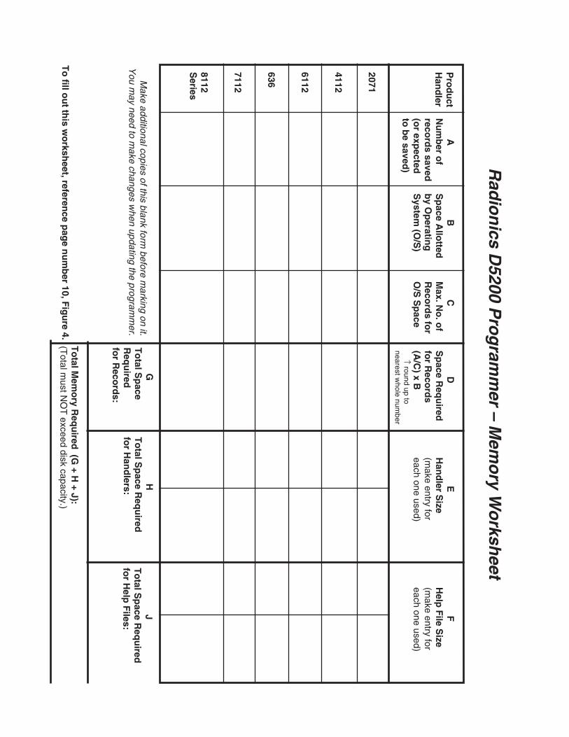
Pro
du
ctH
and
ler AN
um
ber o
freco
rds saved
(or exp
ectedto
be saved
)
CM
ax. No
. of
Reco
rds fo
rO
/S S
pace
DS
pace R
equ
iredfo
r Reco
rds
(A/C
) x B ↑
round up tonearest w
hole number
2071
4112
6112
636
7112
8112S
eries
BS
pace A
llotted
by O
peratin
gS
ystem (O
/S)
FH
elp F
ile Size
(make entry for
each one used)
EH
and
ler Size
(make entry for
each one used)
To
tal Mem
ory R
equ
ired (G
+ H + J):
(Total m
ust NO
T exceed disk capacity.)
JT
otal S
pace R
equ
iredfo
r Help
Files:
HT
otal S
pace R
equ
iredfo
r Han
dlers:
GT
otal S
pace
Req
uired
for R
ecord
s:
Rad
ion
ics D5200 P
rog
ramm
er – Mem
ory W
orksh
eet
Make additional copies of this blank form
before marking on it.
You m
ay need to make changes w
hen updating the programm
er.
To
fill ou
t this w
orksh
eet, reference p
age n
um
ber 10, F
igu
re 4.


![D5200 Programmer - AlarmHow.net Programmer/D5200...D5200 Programmer FEATURES w4-Line Liquid Crystal Display wCustom Keyboard [Load, Copy, Navigate] wUp to 8 programmable passwords](https://img.pdfslide.net/doc/110x75/5aaf114b7f8b9a190d8ce28c/d5200-programmer-programmerd5200d5200-programmer-features-w4-line-liquid-crystal.jpg)