Embed Size (px)
Citation preview
D633 and D634 SeriesProportional Control Valves with Integrated 24 Volt ElectronicsISO 4401 Size 03 and 05
MOOG SERVO-PROPORTIONAL CONTROL VALVES
For over 25 years Moog has manufactured proportional con-trol valves with integrated electronics. During this time morethan 150,000 valves have been delivered. These proportionalcontrol valves have been proven to provide reliable control ofinjection and blow molding equipment, die casting machines,presses, heavy industry equipment, paper and lumber process-ing and other applications.
D633/D634 SERVO-PROPORTIONAL CONTROL VALVES
The D633 and D634 Series are Direct Drive Valves (DDV) withelectric closed loop spool position control. These valves arethrottle valves for 3-, 4-, and 2x2-way applications. They aresuitable for electrohydraulic position, velocity, pressure orforce control systems, including those with high dynamicresponse requirements.
The spool drive device is a permanent magnet linear force motor,which can actively stroke the spool from its spring-centered posi-tion in both directions, as compared with most proportionalsolenoids with one force direction only.
Our DDV Servo-Proportional Control Valves have 24V DC on-board, closed loop spool position and drive electronics. Thisintegrated electronic features SMD technology and is pulsewidth modulated (PWM).
2 Moog • D633/D634 Series
OVERVIEW D/DSection Page
Overview 2-3
Technical Data 4-5
Electronics 6-7
Performance Specs 8-11
Ordering Information 12
Our quality management systemis certified in accordance with DINEN ISO 9001.
The valve series described in thiscatalog have successfully passedEMC tests required by ECDirective. Please refer to therespective references in the elec-tronics section.
Valves available with explosionprotection to EN 50018 and55019, class II 2G EExde B+H2 T4,DMT 00 ATEX E 037, 0470 at D633series and II 2G EExde B+H2 T3,DMT 00 ATEX E 037, 0470 at D634series. Note: Installation dimensions andelectric connection altered.Special data sheet on request.
Meets EN60529 class IP65 require-ment.
This catalog is for users with technical knowledge.To ensure that all necessary characteristics for func-tion and safety of the system are given, the user hasto check the suitability of the products describedherein. In case of doubt, please contact Moog.
ImportantBefore installation of the valve into the sys-tem, the complete hydraulic system must beflushed.
Please read the notes in section “Electronics”,page 6.
FEATURES & BENEFITS
Moog • D633/D634 Series 3
D/DHigh Dynamics for Faster Step ResponseThe high natural frequency of the Direct Drive Valve (300 Hz ±10%) results in one of the highest dynamic servo-proportionalvalves on the market.
High Pressure Gain of Direct Drive Pilot Valve for ReliableOperationThe valve's high-pressure gain offers improved spool positioncontrol even in situations with high internal flow forces and con-taminated fluids.
Direct Drive Pilot Valve for Dynamic Performance Independentof System PressureThe electro-mechanical design of the Direct Drive Valve resultsin dynamic performance of the valve that is independent of sys-tem pressure.
Improved Resistance to Contamination Reduces Down TimeThe DDV Series Valves have high spool driving forces offeringgreater chip shearing forces, making the valve more tolerant tocontamination.
Flexible Design Elements Optimize the Valve to Your ApplicationThe DDV Series Valves offer a variety of flow characteristics suchas linear, dual-gain, and curvilinear in flow ranges from 1.5 to 26gpm (5 to 40 lpm).
Fail-Safe Versions for Defined Spool Position at Loss of PowerThe spring offers automatic centering of the spool at loss ofpower, without passing a load move position. In addition, a trimadjustment can be set to a customer’s requirement.
Low Current Consumption Saves EnergyThe linear force motor allows for low current consumption innormal operation and near hydraulic null, saving energy espe-cially in multiple valve applications.
Monitoring Signal for Evaluating System Integrity6+PE pole connector allows access to a standardized spool posi-tioning monitoring signal with low residual ripple.
High Flow Capability for High Velocity ApplicationsThe D03 and D05 (NG6 and NG10) DDV Series valves offer highflow per body size.
Low Hysteresis and Low Threshold for Better ControlThe linear force motor combined with a spool and bushingdesign offers better overall system control.
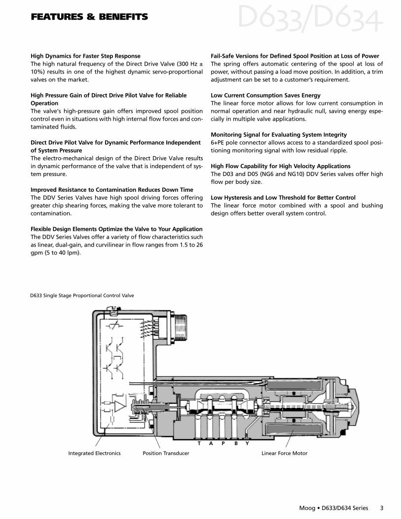
D633 Single Stage Proportional Control Valve
Position Transducer Linear Force MotorIntegrated Electronics
T A P B Y

4 Moog • D633/D634 Series
D/DTECHNICAL DATA
OPERATING PRINCIPLES OF THE DIRECT DRIVE VALVES (DDV)
Null Adjust Cover Plug
Valve Connector
Position Transducer Linear Force Motor
Centering Spring
Integrated Electronics
Spool
T A P B Y
Bushing
OPERATING PRINCIPLES OF THE PERMANENT LINEAR FORCE MOTOR
The linear force motor is a permanent magnet differentialmotor. The permanent magnets provide part of the requiredmagnetic force. For the linear force motor the current needed isconsiderably lower than would be required for a comparableproportional solenoid.The linear force motor has a neutral mid-position from which it generates force and stroke in both direc-tions. Force and stroke are proportional to current.
High spring stiffness and resulting centering force plusexternal forces (i.e. flow forces, friction forces due to contami-nation) must be overcome during out-stroking. During back-
stroking to centre position the spring force adds to the motorforce and provides additional spool driving force which makesthe valve very less contamination sensitive. The linear forcemotor needs very low current in the spring centered position.
Proportional solenoid systems require for the same functiontwo solenoids with more cabling. Another solution uses a singlesolenoid, working against a spring. In case of current loss in thesolenoid, the spring drives the spool to the end position by pass-ing through a fully open position. This can lead to uncontrolledload movements.
Plug
ArmatureCoilBearing
Permanent MagnetsCable Hole Centering Springs
Hydraulic symbol:Symbol shown with pilot pressure and electric supply on and zero com-mand signal.
The position control loop for the spool with position transducerand linear force motor is closed by the integrated electronics. Anelectric signal corresponding to the desired spool position isapplied to the integrated electronics and produces a pulsewidth modulated (PWM) current to drive the linear force motor.An oscillator excites the spool position transducer (LVDT) pro-ducing an electric signal proportional to spool position.
The demodulated spool position signal is compared withthe command signal and the resulting spool position error caus-es current in the force motor coil until the spool has moved toits commanded position, and the spool position error is reducedto zero. The resulting spool position is thus proportional to thecommand signal.
Moog • D633/D634 Series 5
D/DTECHNICAL DATA
PERFORMANCE SPECIFICATIONS FOR STANDARD MODELS
Flo
w R
ate
Q [
l/min
]
∆p m
ax =
350
bar
Valve Flow Drop ∆p [bar]
200
150
10080
60
40
30
20
15
10
8
6
4
3
2
110 20 30 50 70 100 150 200 350
D634
D634
D633
D633
D633
D633
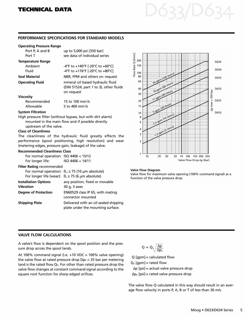
11 gpm [40 l/min]
5 gpm [20 l/min]
2.5 gpm [10 l/min]
1.3 gpm [5 l/min]
16 gpm [60 l/min]26 gpm [100 l/min]
Valve Flow DiagramValve flow for maximum valve opening (100% command signal) as afunction of the valve pressure drop
Operating Pressure RangePort P, A and B up to 5,000 psi [350 bar]Port T see data of individual series
Temperature Range Ambient -4°F to +140°F [-20°C to +60°C]Fluid -4°F to +176°F [-20°C to +80°C]
Seal Material NBR, FPM and others on request
Operating Fluid mineral oil based hydraulic fluid (DIN 51524, part 1 to 3), other fluids on request
ViscosityRecommended 15 to 100 mm2/sAllowable 5 to 400 mm2/s
System FiltrationHigh pressure filter (without bypass, but with dirt alarm)
mounted in the main flow and if possible directlyupstream of the valve.
Class of CleanlinessThe cleanliness of the hydraulic fluid greatly effects the performance (spool positioning, high resolution) and wear(metering edges, pressure gain, leakage) of the valve.
Recommended Cleanliness ClassFor normal operation: ISO 4406 < 15/12For longer life: ISO 4406 < 14/11
Filter Rating recommendedFor normal operation: ß10 ≥ 75 (10 µm absolute)For longer life (wear): ß6 ≥ 75 (6 µm absolute)
Installation Options any position, fixed or movableVibration 30 g, 3 axes
Degree of Protection EN60529 class IP 65, with mating connector mounted
Shipping Plate Delivered with an oil sealed shippingplate under the mounting surface.
VALVE FLOW CALCULATIONS
A valve’s flow is dependent on the spool position and the pres-sure drop across the spool lands.
At 100% command signal (i.e. +10 VDC = 100% valve opening)the valve flow at rated pressure drop DpN = 35 bar per meteringland is the rated flow QN. For other than rated pressure drop thevalve flow changes at constant command signal according to thesquare root function for sharp edged orifices.
∆pQ = QN
∆pN
Q [gpm] = calculated flow
QN [gpm] = rated flow
∆p [psi] = actual valve pressure drop
∆pN [psi] = rated valve pressure drop
The valve flow Q calculated in this way should result in an aver-age flow velocity in ports P, A, B or T of less than 30 m/s.
ELECTRONICS D/D
6 Moog • D680 Series
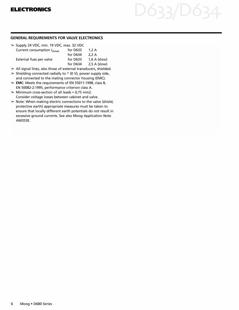
GENERAL REQUIREMENTS FOR VALVE ELECTRONICS
Supply 24 VDC, min. 19 VDC, max. 32 VDC Current consumption IAmax for D633 1,2 A
for D634 2,2 AExternal fuse per valve for D633 1,6 A (slow)
for D634 2,5 A (slow) All signal lines, also those of external transducers, shielded. Shielding connected radially to ^ (0 V), power supply side,
and connected to the mating connector housing (EMC). EMC: Meets the requirements of EN 55011:1998, class B,
EN 50082-2:1995, performance criterion class A. Minimum cross-section of all leads ≈ 0,75 mm2.
Consider voltage losses between cabinet and valve. Note: When making electric connections to the valve (shield,
protective earth) appropriate measures must be taken to ensure that locally different earth potentials do not result in excessive ground currents. See also Moog Application Note AM353E.

CIRCUIT DIAGRAM
ELECTRONICS D/DVALVE ELECTRONICS WITH SUPPLY VOLTAGE 24 VOLT AND 6+PE POLE CONNECTOR
Command signal 0 to ±10 mA floating,Valves with current command inputThe spool stroke of the valve is proportional to ID = –IE. 100% valve opening P A and B T is achieved at ID = +10 mA. At 0 mA command the spool is in centered position. The inputpins D and E are inverting. Either pin D or E is used according tothe required operating direction. The other pin is connected tosignal ground at cabinet side.
Command signal 0 to ±10 V,Valves with voltage command inputThe spool stroke of the valve is proportional to (UD – UE). 100% valve opening P A and B T is achieved at (UD – UE) = +10V. At 0 V command the spool is in centered position. The inputstage is a differential amplifier. If only one command signal is avail-able, pin D or E is connected to signal ground at cabinet side,according to the required operating direction.
Actual value 4 to 20 mAThe actual spool position value can be measured at pin F (seediagram below). This signal can be used for monitoring andfault detection purposes. The spool stroke range corresponds to4 to 20 mA.
The centered position is at 12 mA. 20 mA corresponds to 100%valve opening P A and B T. The position signal output 4 to 20mA allows to detect a cable break when IF = 0 mA.
For failure detection purposes it is advised to connect pin F of themating connector and route this signal to the control cabinet.
Note: Enable inputWith enable signal off, the main spool will move to a safe position.a) Centered position (unbiased pilot valve function code A1)b) End position (biased pilot valve function code B1)
1) see type designation
CONNECTOR WIRING Wiring for valves with 6+PE pole connector to EN 175201 Part 8042), and matingconnector (type R and S, metal shell) with leading protective earth connection .
Circuit diagram for measurement of actual IF (position of mainspool) for valves with 6+PE pole connector
Moog • D633/D634 Series 7
F
B
V=
R =R =500500 Ω
UF
IF
valveside
4 to 20mAmA
SpoolSpool strokeoke rangerangeU 2 to 1010 VF =centrcentreded positionposition atat 6 V
PE
F
E
D
C
B
A
MachineSide
Mating ConnectorConnectorValve
Protective Earth
OutputActual Spool Position
I F-B = 4 to 20mA. At 12 mA spool is centered position RL = 300 to 500 Ω.
U D-E = 0 to ±10 V Input Command ID = - IE:0 to ± 10mARe = 10 kΩ Input Command (Inverted) IE = - ID:0 to ± 10mAInput Voltage U D-E and U E-B for both signal types is limited to min. -15V, max. +24V
Input Rated Command(Differential)
Not Used
⊥ (0 V)Supply / Signal Ground
Current Command0 to ±10 mA
Voltage Command0 to ±10 VDCFunction Current Command
+ 4 … +20 mA
Supply 24 VDC (19 to 32 VDC) (D633 only 22 to 28 VDC)*
(Re = 200
1) formerly DIN 43563, *before 01.01.2001
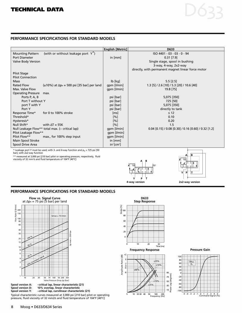
PERFORMANCE SPECIFICATIONS FOR STANDARD MODELS
TECHNICAL DATA DPERFORMANCE SPECIFICATIONS FOR STANDARD MODELS
8 Moog • D633/D634 Series
5 10 20 30 40 50 100 200
-6-4-2
0
+2
-8
Frequency [Hz]
Am
plit
ud
e R
atio
[d
B]
±25%
±10%
±10%
±25%
±90%-90
-70
-50
-30
-10
Phas
e La
g [
deg
rees
]
Frequency Response
D633Step Response
Spool version A: ~critical lap, linear characteristic (21)Spool version D: 10% overlap, linear characteristicSpool version Y: ~critical lap, curvilinear characteristic (21)Typical characteristic curves measured at 3,000 psi [210 bar] pilot or operatingpressure, fluid viscosity of 32 mm2/s and fluid temperature of 104°F [40°C]
100
80
60
40
20
0
10 20 300Time [ms]
Stro
ke [%
]
Flow vs. Signal Curveat ∆pN = 75 psi [5 bar] per land
4-way version 2x2-way version
* Leakage port Y must be used; with 3- and 4-way function and pT > 725 psi [50bar]; with 2x2-way function
** measured at 3,000 psi [210 bar] pilot or operating pressure, respectively, fluidviscosity of 32 mm2/s and fluid temperature of 104°F [40°C]
English [Metric] D633Mounting Pattern (with or without leakage port Y*) ISO 4401 - 03 - 03 - 0 - 94Port Diameter in [mm] 0.31 [7.9]Valve Body Version Single stage, spool in bushing
3-way, 4-way, 2x2-waydirectly, with permanent magnet linear force motor
Pilot StagePilot Connection Mass lb [kg] 5.5 [2.5]Rated Flow (±10%) at ∆pN = 500 psi [35 bar] per land gpm [l/min] 1.3 [5] / 2.6 [10] / 5.3 [20] / 10.6 [40]Max. Valve Flow gpm [l/min] 19.8 [75]Operating Pressure max.
Ports P, A, B psi [bar] 5,075 [350]Port T without Y psi [bar] 725 [50]port T with Y psi [bar] 5,075 [350]Port Y psi [bar] directly to tank
Response Time* for 0 to 100% stroke [ms] ≤ 12Threshold* [%] 0.10Hysteresis* [%] 0.20Null Shift* with ∆T = 55K [%] 1.5Null Leakage Flow** total max. (~ critical lap) gpm [l/min] 0.04 [0.15] / 0.08 [0.30] / 0.16 [0.60] / 0.32 [1.2]Pilot Leakage Flow** gpm [l/min]Pilot Flow** max., for 100% step input gpm [l/min]Main Spool Stroke in [mm]Spool Drive Area in2 [cm2]
Flo
w R
ate
Q [
l/min
]
∆p m
ax =
350
bar
Valve Pressure Drop ∆p [bar]
200
150
10080
60
40
30
20
15
10
8
6
4
3
2
110 20 30 50 70 100 50 200 350
100 %
50 %
20 %
10% Command signal
Qmax = 75 l/min
Command Signal [%]
100
60
80
40
200
-20
-40
-60
-80
-100
-5 -4 -3 -2 -1 0 1 2 3 4 5
∆pAB
Pp
Pressure Gain
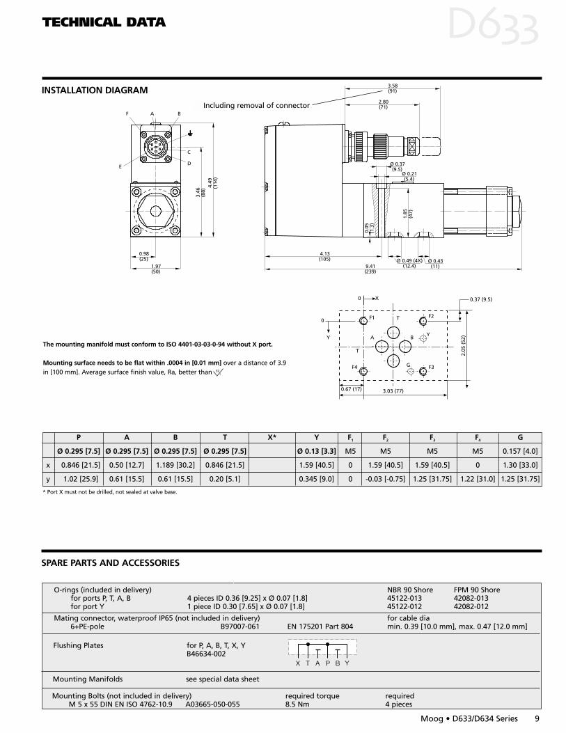
SPARE PARTS AND ACCESSORIES
O-rings (included in delivery) NBR 90 Shore FPM 90 Shorefor ports P, T, A, B 4 pieces ID 0.36 [9.25] x Ø 0.07 [1.8] 45122-013 42082-013for port Y 1 piece ID 0.30 [7.65] x Ø 0.07 [1.8] 45122-012 42082-012
Mating connector, waterproof IP65 (not included in delivery) for cable dia6+PE-pole B97007-061 EN 175201 Part 804 min. 0.39 [10.0 mm], max. 0.47 [12.0 mm]
Mounting Manifolds see special data sheet
Mounting Bolts (not included in delivery) required torque requiredM 5 x 55 DIN EN ISO 4762-10.9 A03665-050-055 8.5 Nm 4 pieces
Flushing Plates for P, A, B, T, X, YB46634-002
The mounting manifold must conform to ISO 4401-03-03-0-94 without X port.
Mounting surface needs to be flat within .0004 in [0.01 mm] over a distance of 3.9in [100 mm]. Average surface finish value, Ra, better than 32.
P A B T X* Y F1 F2 F3 F4 G
Ø 0.295 [7.5] Ø 0.295 [7.5] Ø 0.295 [7.5] Ø 0.295 [7.5] Ø 0.13 [3.3] M5 M5 M5 M5 0.157 [4.0]
x 0.846 [21.5] 0.50 [12.7] 1.189 [30.2] 0.846 [21.5] 1.59 [40.5] 0 1.59 [40.5] 1.59 [40.5] 0 1.30 [33.0]
y 1.02 [25.9] 0.61 [15.5] 0.61 [15.5] 0.20 [5.1] 0.345 [9.0] 0 -0.03 [-0.75] 1.25 [31.75] 1.22 [31.0] 1.25 [31.75]
TECHNICAL DATA D
Moog • D633/D634 Series 9
INSTALLATION DIAGRAM
B
C
DE
F A
0.98(25)
1.97(50)
3.46
(88)
4.49
(114
)
9.41(239)
4.13(105) Ø 0.49 (4X)
(12.4)Ø 0.43
(11)
1.85
(47)
0.05
(1.3
)
Ø 0.37(9.5)
3.58(91)
2.80(71)
Ø 0.21(5.4)
Including removal of connector
* Port X must not be drilled, not sealed at valve base.
F1
3.03 (77)
F4
A B
F2T
Y
F3
0 X
0.67 (17)
0
Y
T
2.05
(52
)
0.37 (9.5)
G

PERFORMANCE SPECIFICATIONS FOR STANDARD MODELS
TECHNICAL DATA DPERFORMANCE SPECIFICATIONS FOR STANDARD MODELS
10 Moog • D633/D634 Series
±10%
±10%
5 10 20 30 40 50 100 200
-90
-70
-50
-30
-10
-6-4-2
0
+2
-8
±25%
±90%
±25%
Frequency Response
D634Step Response
Spool version A: ~critical lap, linear characteristic (21)Spool version D: 10% overlap, linear characteristicSpool version Y: ~critical lap, curvilinear characteristic (21)Typical characteristic curves measured at 3,000 psi [210 bar] pilot or operatingpressure, fluid viscosity of 32 mm2/s and fluid temperature of 104°F [40°C]
100
80
60
40
20
0
10 20 300Time [ms]
Stro
ke [%
]
Flow vs. Signal Curveat ∆pN = 75 psi [5 bar] per land
4-way version 2x2-way version
* Leakage port Y must be used; with 3- and 4-way function and pT > psi [50 bar];with 2x2-way function
** measured at 3,000 psi [210 bar] pilot or operating pressure, respectively, fluidviscosity of 32 mm2/s and fluid temperature of 104°F [40°C]
English [Metric] D634Mounting Pattern (with or without leakage port Y*) ISO 4401 - 05 - 05 - 0 - 94Port Diameter in [mm] 0.45 [11.5]Valve Body Version Single stage, spool in bushing
3-way, 4-way, 2x2-waydirectly, with permanent magnet linear force motor
Pilot StagePilot Connection Mass lb [kg] 13.9 [6.3]Rated Flow (±10%) at ∆pN = 500 psi [35 bar] per land gpm [l/min] 16 [60] / 26 [100]Max. Valve Flow gpm [l/min] 48.9 [185]Operating Pressure max.
Ports P, A, B psi [bar] 5,075 [350]Port T without Y psi [bar] 725 [50]port T with Y psi [bar] 5,075 [350]Port Y psi [bar] directly to tank
Response Time* for 0 to 100% stroke [ms] ≤ 20Threshold* [%] 0.10Hysteresis* [%] 0.20Null Shift* with ∆T = 55K [%] 1.5Null Leakage Flow** total max. (~ critical lap) gpm [l/min] 0.32 [1.2] / 0.53 [2.0]Pilot Leakage Flow** gpm [l/min]Pilot Flow** max., for 100% step input gpm [l/min]Main Spool Stroke in [mm]Spool Drive Area in2 [cm2]
Flo
w R
ate
Q [
l/min
]
∆p m
ax =
350
bar
Valve Pressure Drop ∆p [bar]
200
150
10080
60
40
30
20
15
10
8
6
4
3
2
110 20 30 50 70 100 50 200 350
100 %
50 %
20 %
10% Command signal
Qmax = 75 l/min
Command Signal [%]
100
60
80
40
200
-20
-40
-60
-80
-100
-5 -4 -3 -2 -1 0 1 2 3 4 5
∆pAB
Pp
Pressure Gain
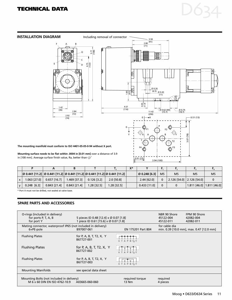
The mounting manifold must conform to ISO 4401-05-05-0-94 without X port.
Mounting surface needs to be flat within .0004 in [0.01 mm] over a distance of 3.9in [100 mm]. Average surface finish value, Ra, better than 32.
P A B T T2 X* Y F1 F2 F3 F4
Ø 0.441 [11.2] Ø 0.441 [11.2] Ø 0.441 [11.2] Ø 0.441 [11.2] Ø 0.441 [11.2] Ø 0.248 [6.3] M5 M5 M5 M5
x 1.063 [27.0] 0.657 [16.7] 1.469 [37.3] 0.126 [3.2] 2.0 [50.8] 2.44 [62.0] 0 2.126 [54.0] 2.126 [54.0] 0
y 0.248 [6.3] 0.843 [21.4] 0.843 [21.4] 1.28 [32.5] 1.28 [32.5] 0.433 [11.0] 0 0 1.811 [46.0] 1.811 [46.0]
TECHNICAL DATA D
Moog • D633/D634 Series 11
INSTALLATION DIAGRAM
F A B
C
DE
5.77
(148
)
4.75
(122
)
1.42(36)
2.84(72)
2.92(74)
11.42(290)
4.57(116)
1.85
(47)
3.58(91)
2.80(71)
Ø 0.26(6.5) Ø 0.43
(11)
0.05
(1.3
)
Ø 0.62 (4X) (15.7)
Ø 0.74 (18.7)
Including removal of connector
* Port X must not be drilled, not sealed at valve base.
SPARE PARTS AND ACCESSORIES
O-rings (included in delivery) NBR 90 Shore FPM 90 Shorefor ports P, T, A, B 5 pieces ID 0.48 [12.4] x Ø 0.07 [1.8] 45122-004 42082-004for port Y 1 piece ID 0.61 [15.6] x Ø 0.07 [1.8] 45122-011 42082-011
Mating connector, waterproof IP65 (not included in delivery) for cable dia6+PE-pole B97007-061 EN 175201 Part 804 min. 0.39 [10.0 mm], max. 0.47 [12.0 mm]
Mounting Manifolds see special data sheet
Mounting Bolts (not included in delivery) required torque requiredM 6 x 60 DIN EN ISO 4762-10.9 A03665-060-060 13 Nm 4 pieces
Flushing Plates for P, A, B, T, T2, X, YB67727-001
Flushing Plates for P, A, B, T, T2, X, YB67727-002
Flushing Plates for P, A, B, T, T2, X, YB67727-003
F1
3.94 (100)
X
F4
A B
F2P
Y
F3
T2
0 X
0.91 (23)
0
Y
T
3.07
(78
)
0.51 (13)

Preferred configurations are highlighted. Options may increaseprice.Technical changes are reserved.All combinations may not be available. For special options, lettersnot on the information above may be applied. Please contact Moog.
ORDERING INFORMATION D/D
12 Moog • D633/D634 Series
S 6+PE pole (7/8-20 UNF 2A) DIN 43563
2 Standard D634
Z 2x2-way: P A, B T, with Y port only
B P B, A T (10% open, min.)
Other openings on request
1 Open, with filter insert PT > 715 psi[50 bar]
Series
E Preseries specification
K explosion proof versionupon request
D63 .
Model Designation
Factory Identification
Valve Version
R With integrated electronics
Spool Position without Electrical Supply
Supply Voltage
2 +24 VDC (22 to 28 VDC)
Signals for 100% Spool Stroke
Command Output
M ±10 VDC +4 to +20 mAP 0 to ±10 mA +4 to +20 mAS +4 to +20 mA +4 to +20 mAX ±10 mA, floating +4 to +20 mA
Valve Connector
Seal Material
N NBR (Buna)
V FPM (Viton)
Other materials on request
0 Closed with plug PT max = 715 psi[50 bar]
M Mid-position
Specification Status
– Series specification
Z Special specification
Assigned at the factory
Rated Flow
Maximum Operating Pressure
Bushing Spool Type
Linear Force Motor Series
K 350 bar
A 4-way: 1.5 to 3% overlap, linear characteristic
D 4-way: 10% overlap, linear characteristic
X Special spool on request
1 Standard D633
O 4-way: axis cut, linear characteristic
3 Size 034 Size 05
Model Number Type Designation
A P B, A T (10% open, min.)
02 5 2 D63304 10 4 D63308 20 8 D63316 40 16 D63324 60 24 D63440 100 40 D634
QN[l/min] at ∆pN = 500 psi[35 bar] ∆pN = 75 psi[5 bar] per land Series
. . . . . . . . . . . .
Y - Port
. . . . .

NOTES D/D
Moog • D633/D634 Series 13
NOTES D/D
14 Moog • D633/D634 Series
Moog Industrial Controls Division East Aurora, NY 14052-0018Telephone: 716/655-3000Fax: 716/655-1803 Toll Free: 1-800-272-MOOGwww.moog.com
CDL6581 Rev E 500-189 601
ArgentinaAustraliaAustriaBrazilChinaEnglandFinlandFranceGermany
IndiaIrelandItalyJapanKoreaLuxembourgNorwayRussiaSingaporeSpainSwedenUSA