Embed Size (px)
Citation preview
www.baumer.com
D920Flanged diaphragm seal with flush diaphragm
2015
-11-
04
D
esig
n an
d sp
ecifi
catio
ns s
ubje
ct to
cha
nge
with
out n
otic
e
Page 1 / 4Data sheet A42.13
D920Flanged diaphragm seal with flush diaphragm
Main Features
Applications
�� Pressure range from 25 mbar to 400 bar �� Flush diaphragm�� Temperature -40 °C … 400 °C�� Optimized for assembly with transmitters
�� Class 150 to 2500 �� NPS 2" to 4" �� PN10 to PN100�� DN50 to DN100
�� Oil & Gas / Chemical�� Water / Waste water�� Energy�� Process technic
Technical Data
Materials
This diaphragm seals with flanged process connection and flush diaphragm are used to protect pressure transmitters from high tempe-ratures, aggressive or corrosive fluids.The flush diaphragm allows direct mounting on standardized flange connections of pipes or tanks. With the flush diaphragm these seals are used especially for fluids with high viscosity or a tendency to crystallize. Different diaphragm materials can be selected to adapt the seal to various applications and process fluids. Only the active part of the diaphragm is made of specific materials. The flange face is always stainless steel.The diaphragm seals D92x have been developed especially for the mea-surement of low pressure ranges in applications with high overpressure resistance or high static pressure. They are designed for assembly with electronic transmitters for pressure or differential pressure, which can also be used for level or flow measurement. The D92x series cannot be used with pressure gauges. For pressure gauges the series D82x has to be used.The filling fluid of the measuring system has to be choosen compatible to the application.
Min.pressure ranges See table on page 2Temperature -40 °C ... +400 °C Filling liquids LRS4: -20 ... 60 °C (for oxygen)
LRS8: 0 ... 300 °C (for vacuum and absolutepressure)LRS9: -40 ... 400 °C (high temperature oil)Other liquids on request
Mounting Direct or remote from 1.5 to 12 metersFlange material Stainless steel 1.4404 (AISI 316L)Flange types ASME B16.5 / EN1759-1:
class 150 to 2500, NPS 2" to 4".EN1092-1:PN 10 to 100, DN 50 to 100.Available flange faces see table on page 3. Other flange types on request.
Diaphragm Stainless steel 1.4435 (AISI 316L)Option: Hastelloy, Uranus, Tantalum (see orde-ring details on page 4)
Maximum pressure According to the PN or the class of the flange and its standardized pressure temperature relation
N° D920
Flange Stainless steel 1.4404
Diaphragm Stainless steel 1.4435 Hastelloy B2 (2.4617) Hastelloy C276 (2.4819) Hastelloy C4 (2.4610) Uranus B6 (1.4539) Tantalum
Capillary(option) Stainless steel
www.baumer.com
N x ØL
ØM
Ød1
ØK ØD
f1
C
D920Flanged diaphragm seal with flush diaphragm
2015
-11-
04
D
esig
n an
d sp
ecifi
catio
ns s
ubje
ct to
cha
nge
with
out n
otic
e
Page 2 / 4Data sheet A42.13
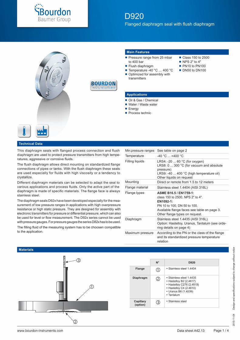
Dimensions (mm)
DN Class Ø D Ø K Ø L NEN1759-1 ANSI B16-5
Ø d1 (1) Ø M in mm (2) Weight in kgC (1) f1 (1) C (1) f1 (1)
2"(DN50)
150 152 120.6 19 4 19 1.6 19.5 2 91.9 54 2.4
300 165 127 19 8 22.2 1.6 22.7 2 91.9 54 3.2
600 165 127 19 8 31.8 6.4 32.4 7 91.9 54 4.2
900/1500 216 165.1 25.4 8 44.5 6.4 45.1 7 91.9 54 10.1
2500 235 171.5 28.5 8 57.2 6.4 57.9 7 91.9 54 15.6
3"(DN80)
150 190 152.4 19 4 23.8 1.6 24.3 2 127 89 5
300 210 168.3 22.2 8 28.6 1.6 29 2 127 89 6.9
600 210 168.3 22.2 8 38.2 6.4 38.8 7 127 89 8.5
900 241 190.5 25.4 8 44.5 6.4 45.1 7 127 89 13.1
1500 267 203.2 31.8 8 54 6.4 54.7 7 127 89 19.2
4"(DN100)
150 229 190.5 19 8 23.8 1.6 24.3 2 157.2 95 7.1
300 254 200 22.2 8 31.8 1,6 32.2 2 157.2 95 11.6
600 273 215.9 25.4 8 44.5 6.4 45.1 7 157.2 95 17.3
900 292 235 31.8 8 50.8 6.4 51.5 7 157.2 95 22.1
Flange dimensions (mm) ANSI B16-5 / EN 1759-1
Ø M (1)
(mm)
Transmitters
Gauge and differential Absolute
54 0 ... 400 mbar n/a
89 0 ... 25 mbar (2) 0 ... 50 mbar
95 0 ... 25 mbar (2) 0 ... 50 mbar
Minimum pressure ranges depending on the active diaphragmdiameter Ø M
(1) Ø M according to dimension tables below.(2) 10 mbar with specific diaphragm (see codification page 4).
DN PN Ø D C (1) Ø K Ø L N f1 (1) Ø d1 (1) Ø M in mm (2) Weight in kg
50
10/16 165 20 125 18 4 3 102 54 2.9
25/40 180 26 135 22 4 3 102 54 3.2
63 195 28 145 26 4 3 102 54 4.6
100 195 30 145 26 4 3 102 54 5.7
80
10/16 200 20 160 18 8 3 138 89 4.6
25/40 200 24 160 18 8 3 138 89 5.6
63 215 28 170 22 8 3 138 89 6.9
100 230 32 180 26 8 3 138 89 8.9
100
10/16 220 20 180 18 8 3 158 95 5.7
25/40 235 24 190 22 8 3 162 95 7.6
63 250 30 200 26 8 3 162 95 10
100 265 36 210 30 8 3 162 95 13.3
Flange dimensions (mm) EN 1092-1
(1) For raised faces, codes B, G, R.(2) Active diameter.
www.baumer.com
D920Flanged diaphragm seal with flush diaphragm
2015
-11-
04
D
esig
n an
d sp
ecifi
catio
ns s
ubje
ct to
cha
nge
with
out n
otic
e
Page 3 / 4Data sheet A42.13
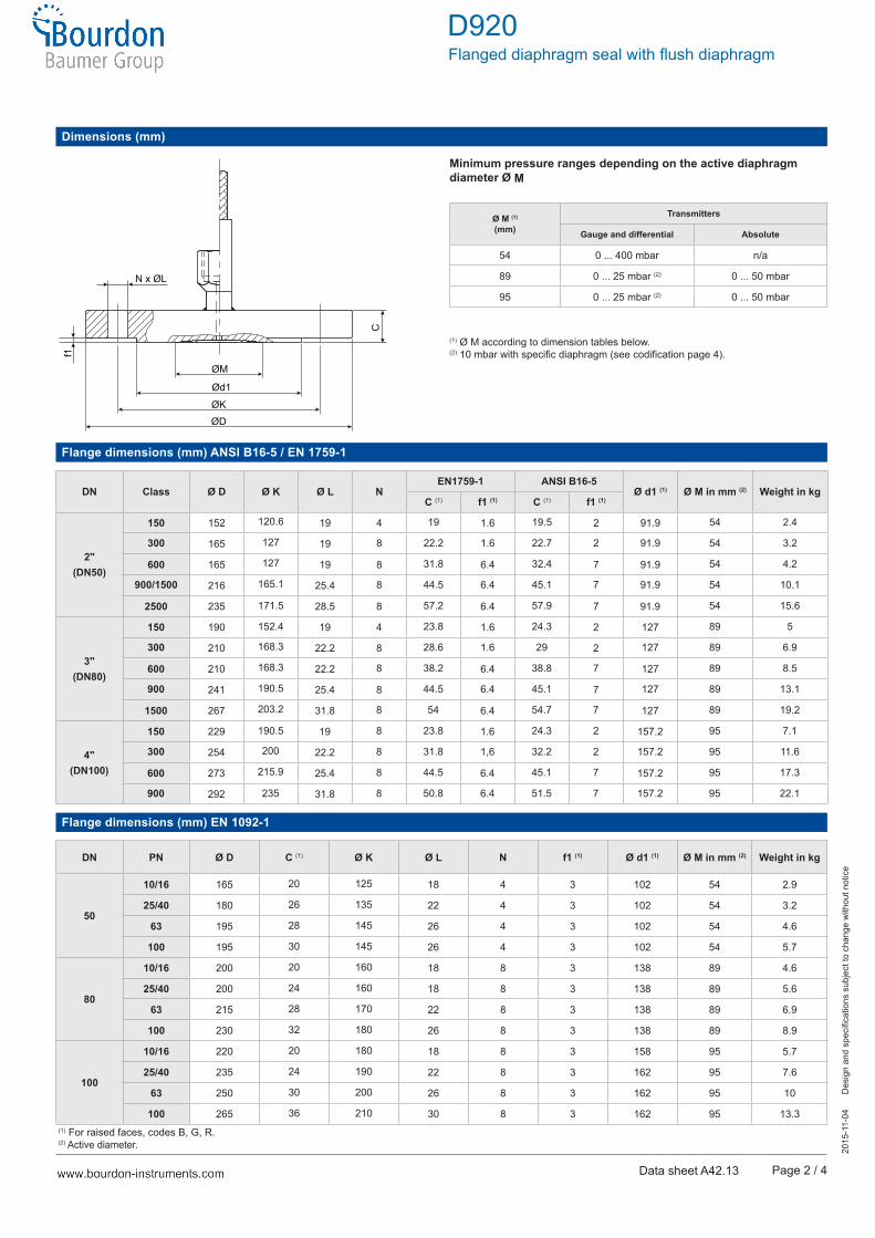
Ordering codes for flange faces
Face Type Drawing ANSI B16-5 EN 1759-1 EN 1092-1Codes Codes Codes
Flat faceFlat face A Type A A Type A A
Ra = 3.2...6.3 µm Ra = 3.2...6.3 µm Ra = 3.2...6.3 µm
Raised faceRaised face (2) (2)
Raised face (7) (3)GR
Type B (1.6) (2)
Type B (6.4) (3)GR
Type B1 B
Ra = 3.2...6.3 µm Ra = 3.2...6.3 µm Ra = 3.2...12.5 µm
Male tongueMale tongue largeMale tongue small
HI
Type CLType CS
HI
Type C C
Ra = 0.8...3.2 µm Ra = 0.8...3.2 µm Ra = 0.8...3.2 µm
Female grooveFemale groove largeFemale groove small
KL
Type DLType DS
KL
Type D D
Ra = 0.8...3.2 µm Ra = 0.8...3.2 µm Ra = 0.8...3.2 µm
Male SpigotMale spigot largeMale spigot small (1)
MN
Type E M Type E E
Ra = 3.2...6.3 µm Ra = 3.2...6.3 µm Ra = 3.2...12.5 µm
Female SpigotFemale spigot largeFemale spigot small (1)
OP
Type FC O Type F F
Ra = 3.2...6.3 µm Ra = 3.2...6.3 µm Ra = 3.2...12.5 µm
Ring joint faceRing joint face Q Type J Q N/A
Ra = 0.4...1.6 µm Ra = 0.4...1.6 µm
(1) Only applicable for 4"(2) Class 150 and 300(3) Class 600, 900, 1500, 2500
Heatable capillary (option)
• Capillary with low-temperature controlled electric heat tracing• Reduce influence of environmental temperature• Improve response time for long capillary• Decrease in effects of outside temperature:
at −40 °C capillary tube temperature over +30 °Cat +40 °C capillary tube temperature below +60 °C
• Approx. Ø 25 mm heat insulation• Sealed outer sheath
www.baumer.com
D920Flanged diaphragm seal with flush diaphragm
2015
-11-
04
D
esig
n an
d sp
ecifi
catio
ns s
ubje
ct to
cha
nge
with
out n
otic
e
Page 4 / 4Data sheet A42.13
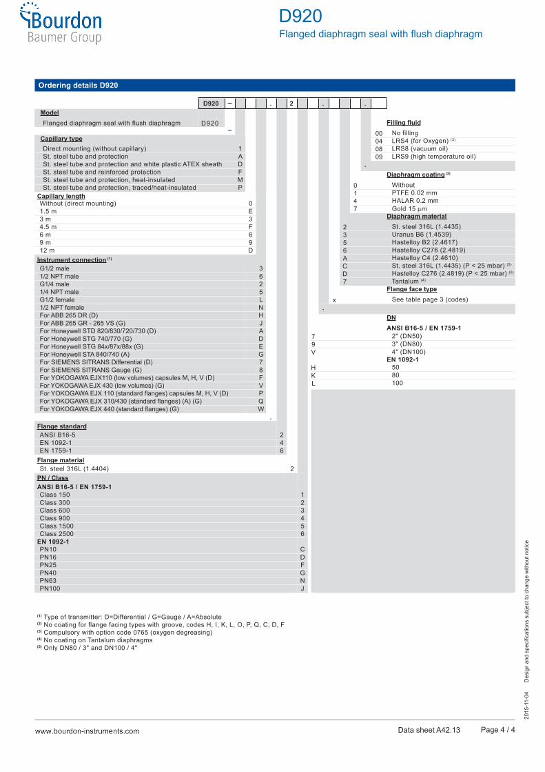
D920 – . 2ModelFlanged diaphragm seal with flush diaphragm D920
–Capillary typeDirect mounting (without capillary) 1St. steel tube and protection ASt. steel tube and protection and white plastic ATEX sheath DSt. steel tube and reinforced protection FSt. steel tube and protection, heat-insulated MSt. steel tube and protection, traced/heat-insulated P
Capillary lengthWithout (direct mounting) 01.5 m E3 m 34.5 m F6 m 69 m 912 m D
Instrument connection (1)
G1/2 male 31/2 NPT male 6G1/4 male 21/4 NPT male 5G1/2 female L1/2 NPT female NFor ABB 265 DR (D) HFor ABB 265 GR - 265 VS (G) JFor Honeywell STD 820/830/720/730 (D) AFor Honeywell STG 740/770 (G) DFor Honeywell STG 84x/87x/88x (G) EFor Honeywell STA 840/740 (A) GFor SIEMENS SITRANS Differential (D) 7For SIEMENS SITRANS Gauge (G) 8For YOKOGAWA EJX110 (low volumes) capsules M, H, V (D) FFor YOKOGAWA EJX 430 (low volumes) (G) VFor YOKOGAWA EJX 110 (standard flanges) capsules M, H, V (D) PFor YOKOGAWA EJX 310/430 (standard flanges) (A) (G) QFor YOKOGAWA EJX 440 (standard flanges) (G) W
.Flange standardANSI B16-5 2EN 1092-1 4EN 1759-1 6
Flange materialSt. steel 316L (1.4404) 2
PN / ClassANSI B16-5 / EN 1759-1Class 150 1Class 300 2Class 600 3Class 900 4Class 1500 5Class 2500 6
EN 1092-1PN10 CPN16 DPN25 FPN40 GPN63 NPN100 J
(1) Type of transmitter: D=Differential / G=Gauge / A=Absolute(2) No coating for flange facing types with groove, codes H, I, K, L, O, P, Q, C, D, F(3) Compulsory with option code 0765 (oxygen degreasing)(4) No coating on Tantalum diaphragms(5) Only DN80 / 3" and DN100 / 4"
. .
Filling fluid00 No filling04 LRS4 (for Oxygen) (3)
08 LRS8 (vacuum oil)09 LRS9 (high temperature oil)
.Diaphragm coating (2)
0 Without1 PTFE 0.02 mm4 HALAR 0.2 mm7 Gold 15 µm
Diaphragm material2 St. steel 316L (1.4435)3 Uranus B6 (1.4539)5 Hastelloy B2 (2.4617)6 Hastelloy C276 (2.4819)A Hastelloy C4 (2.4610)C St. steel 316L (1.4435) (P < 25 mbar) (5)
D Hastelloy C276 (2.4819) (P < 25 mbar) (5)
7 Tantalum (4)
Flange face typex See table page 3 (codes)
.DNANSI B16-5 / EN 1759-1
7 2" (DN50)9 3" (DN80)V 4" (DN100)
EN 1092-1H 50K 80L 100
Ordering details D920