Embed Size (px)
Citation preview
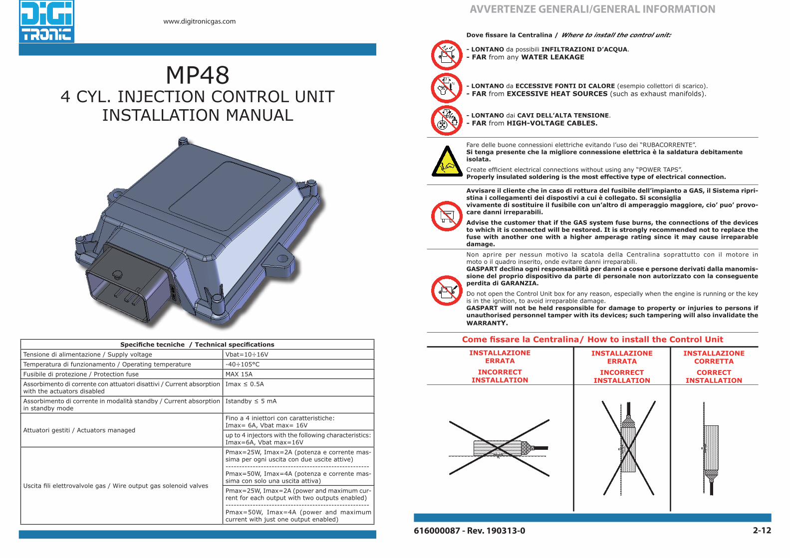
616000087 - Rev. 190313-0 2-12
www.digitronicgas.comAVVERTENZE GENERALI/GENERAL INFORMATION
Dove fissare la Centralina / Where to install the control unit:
- LONTANO da possibili INFILTRAZIONI D’ACQUA.- FAR from any WATER LEAKAGE
- LONTANO da ECCESSIVE FONTI DI CALORE (esempio collettori di scarico).- FAR from EXCESSIVE HEAT SOURCES (such as exhaust manifolds).
- LONTANO dai CAVI DELL’ALTA TENSIONE.- FAR from HIGH-VOLTAGE CABLES.
Fare delle buone connessioni elettriche evitando l’uso dei “RUBACORRENTE”.Si tenga presente che la migliore connessione elettrica è la saldatura debitamente isolata.
Create efficient electrical connections without using any “POWER TAPS”.Properly insulated soldering is the most effective type of electrical connection.
Avvisare il cliente che in caso di rottura del fusibile dell’impianto a GAS, il Sistema ripri-stina i collegamenti dei dispostivi a cui è collegato. Si sconsiglia vivamente di sostituire il fusibile con un’altro di amperaggio maggiore, cio’ puo’ provo-care danni irreparabili.
Advise the customer that if the GAS system fuse burns, the connections of the devices to which it is connected will be restored. It is strongly recommended not to replace the fuse with another one with a higher amperage rating since it may cause irreparable damage.
Non aprire per nessun motivo la scatola della Centralina soprattutto con il motore in moto o il quadro inserito, onde evitare danni irreparabili.GASPART declina ogni responsabilità per danni a cose e persone derivati dalla manomis-sione del proprio dispositivo da parte di personale non autorizzato con la conseguente perdita di GARANZIA.
Do not open the Control Unit box for any reason, especially when the engine is running or the key is in the ignition, to avoid irreparable damage.GASPART will not be held responsible for damage to property or injuries to persons if unauthorised personnel tamper with its devices; such tampering will also invalidate the WARRANTY.
INSTALLAZIONE CORRETTA
CORRECTINSTALLATION
INSTALLAZIONE ERRATA
INCORRECT INSTALLATION
INSTALLAZIONE ERRATA
INCORRECT INSTALLATION
Come fissare la Centralina/ How to install the Control Unit
MP484 CYL. INJECTION CONTROL UNIT
INSTALLATION MANUAL
Specifiche tecniche / Technical specifications
Tensione di alimentazione / Supply voltage Vbat=10÷16V
Temperatura di funzionamento / Operating temperature -40÷105°C
Fusibile di protezione / Protection fuse MAX 15A
Assorbimento di corrente con attuatori disattivi / Current absorption with the actuators disabled
Imax ≤ 0.5A
Assorbimento di corrente in modalità standby / Current absorption in standby mode
Istandby ≤ 5 mA
Attuatori gestiti / Actuators managed
Fino a 4 iniettori con caratteristiche: Imax= 6A, Vbat max= 16V
up to 4 injectors with the following characteristics: Imax=6A, Vbat max=16V
Uscita fili elettrovalvole gas / Wire output gas solenoid valves
Pmax=25W, Imax=2A (potenza e corrente mas-sima per ogni uscita con due uscite attive)-----------------------------------------------------Pmax=50W, Imax=4A (potenza e corrente mas-sima con solo una uscita attiva)
Pmax=25W, Imax=2A (power and maximum cur-rent for each output with two outputs enabled)-----------------------------------------------------Pmax=50W, Imax=4A (power and maximum current with just one output enabled)

616000087 - Rev. 190313-03-12 616000087 - Rev. 190313-04-12
SCHEMA DI POSIZIONAMENTO PT GAS MAP/ PT GAS MAP POSITIONING DIAGRAM
NO
OKSCHEMA DI MONTAGGIO PT GAS MAP/ ASSEMBLY PT GAS MAP DIAGRAM
RIDUTTORE
COLLETTORI DI ASPIRAZIONE
USCITAGAS
PRESSIONECOLLETTORI (MAP)
SENSORE DIPRESSIONE,
TEMPERATURA GAS E MAP
PRESSUREREGULATOR
INTAKE MANIFOLD
OUTGAS
PRESSUREMANIFOLD (MAP)
GAS PRESSURE, TEMPERATURE AND
MAP SENSOR
12
34
0
1/2
4/4
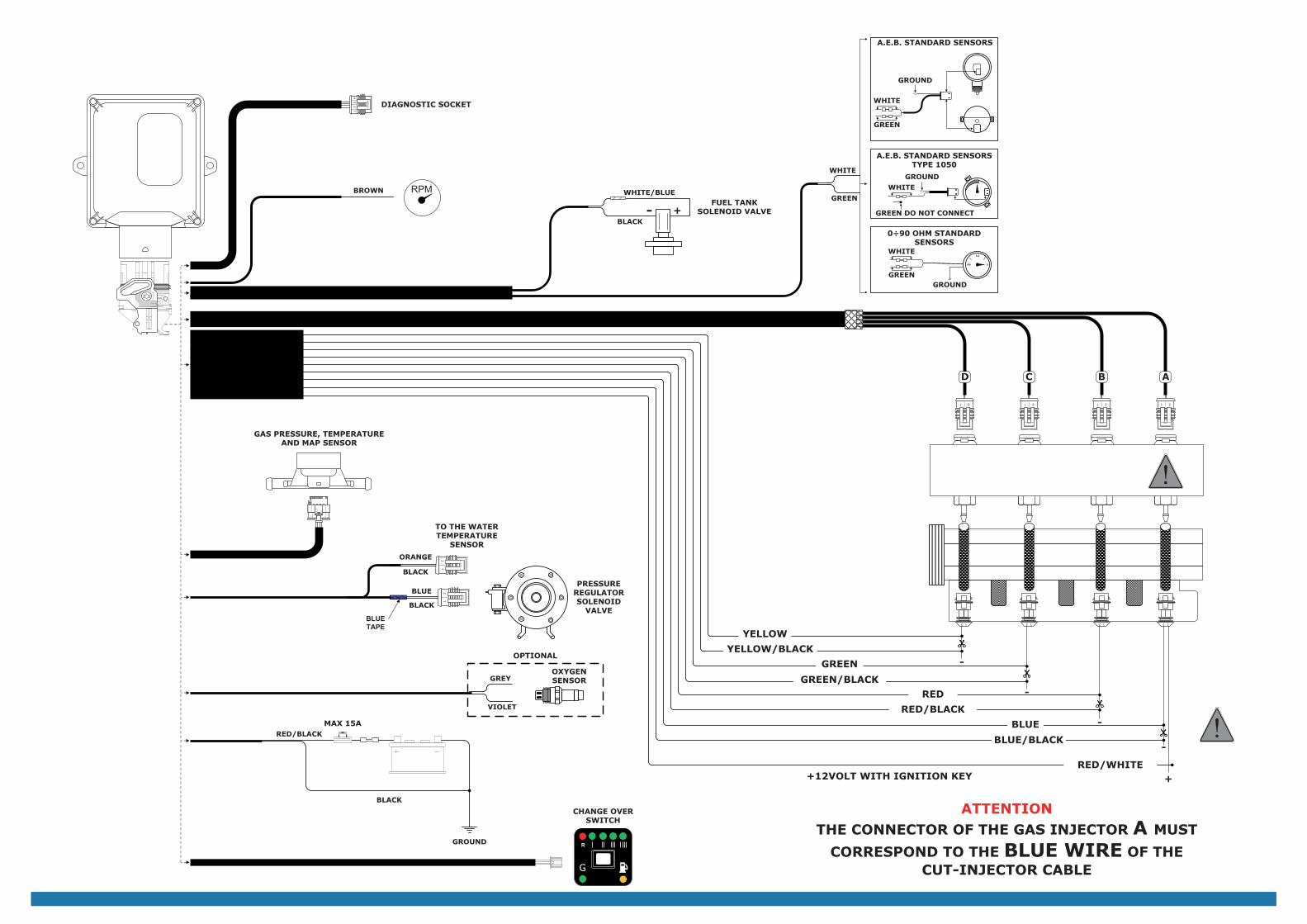
BIANCO
VERDE
BIANCO
VERDE
MASSA
MASSA
BIANCO
VERDE
BIANCO
MASSA
SENSORI STANDARD A.E.B.
SENSORI STANDARD A.E.B. TIPO 1050
SENSORI STANDARD 0÷90 OHM
VERDE NON COLLEGARE
ABCD
12121212
-
-
-
-
VERDE/NERO
VERDE
GIALLO/NERO
GIALLO
ELETTROVALVOLARIDUTTORE
SENSORE DI PRESSIONE, TEMPERATURA GAS E MAP
BLU
BLU/NERO
ROSSO/NERO
ROSSO
BLU
NERO
ROSSO/NERO
NERO
MASSA
1 21 21 21 2
NERO
ARANCIO
ATTENZIONEIL CONNETTORE DELL’INIETTORE GAS
MARCATO A DEVE CORRISPONDERE AL
FILO BLU DEL CAVO STACCA INIETTORI
PRESA DIAGNOSTICA
AL SENSORE TEMPERATURA
ACQUA
12
MARRONE RPM
+ROSSO/BIANCO
+12VOLT SOTTO CHIAVE
G
R
COMMUTATORE
BIANCO/BLUELETTROVALVOLA
SERBATOIONERO
+-
MAX 15A
NASTROBLU
12
GRIGIO
VIOLA
SONDA LAMBDA
OPZIONALE
12
34
0
1/2
4/4
ABCD
12121212
-
-
-
-
1 21 21 21 2
RPM
+
G
R
WHITE
GREEN
WHITE
GREEN
GROUND
GROUND
WHITE
GREEN
WHITE
GROUND
A.E.B. STANDARD SENSORS
A.E.B. STANDARD SENSORS TYPE 1050
0÷90 OHM STANDARD SENSORS
GREEN DO NOT CONNECT
GREEN/BLACK
GREEN
YELLOW/BLACK
YELLOW
GREY
VIOLET
PRESSURE REGULATOR SOLENOID
VALVE
BLUE
BLUE/BLACK
RED/BLACK
RED
BLUE
BLACK
RED/BLACK
BLACK
GROUND
CHANGE OVER SWITCH
BLACK
ORANGE
ATTENTION
THE CONNECTOR OF THE GAS INJECTOR A MUST
CORRESPOND TO THE BLUE WIRE OF THECUT-INJECTOR CABLE
DIAGNOSTIC SOCKET
TO THE WATER TEMPERATURE
SENSOR
OXYGEN SENSOR
BROWN
OPTIONAL
RED/WHITE+12VOLT WITH IGNITION KEY
GAS PRESSURE, TEMPERATURE AND MAP SENSOR
WHITE/BLUEFUEL TANK
SOLENOID VALVEBLACK
+-
MAX 15A
12
BLUETAPE
12
616000087 - Rev. 190313-0 9-12 616000087 - Rev. 190313-010-12
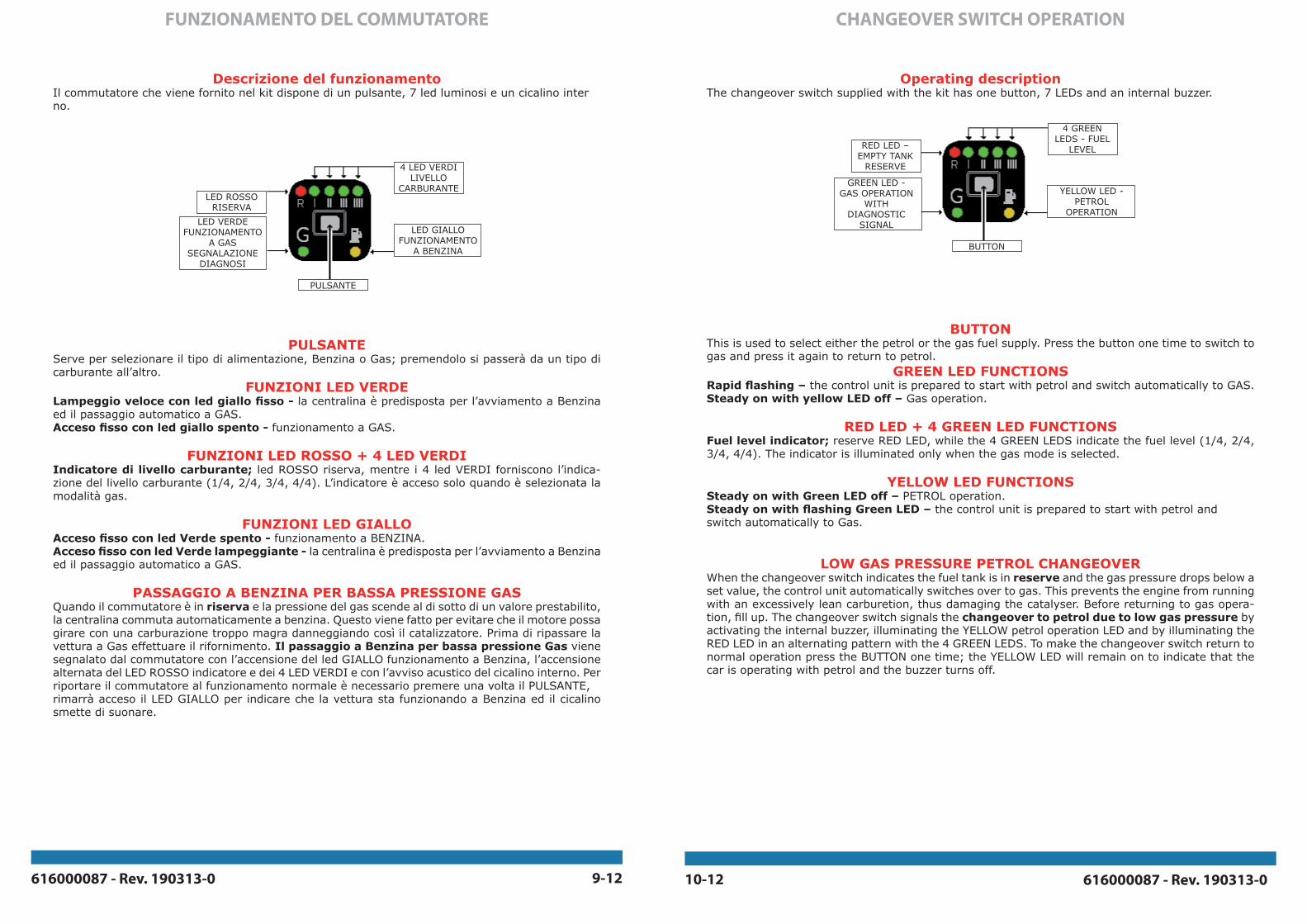
FUNZIONAMENTO DEL COMMUTATORE
Descrizione del funzionamentoIl commutatore che viene fornito nel kit dispone di un pulsante, 7 led luminosi e un cicalino interno.
PULSANTEServe per selezionare il tipo di alimentazione, Benzina o Gas; premendolo si passerà da un tipo di carburante all’altro.
FUNZIONI LED VERDELampeggio veloce con led giallo fisso - la centralina è predisposta per l’avviamento a Benzina ed il passaggio automatico a GAS.Acceso fisso con led giallo spento - funzionamento a GAS.
FUNZIONI LED ROSSO + 4 LED VERDI Indicatore di livello carburante; led ROSSO riserva, mentre i 4 led VERDI forniscono l’indica-zione del livello carburante (1/4, 2/4, 3/4, 4/4). L’indicatore è acceso solo quando è selezionata la modalità gas.
FUNZIONI LED GIALLOAcceso fisso con led Verde spento - funzionamento a BENZINA.Acceso fisso con led Verde lampeggiante - la centralina è predisposta per l’avviamento a Benzina ed il passaggio automatico a GAS.
PASSAGGIO A BENZINA PER BASSA PRESSIONE GASQuando il commutatore è in riserva e la pressione del gas scende al di sotto di un valore prestabilito, la centralina commuta automaticamente a benzina. Questo viene fatto per evitare che il motore possa girare con una carburazione troppo magra danneggiando così il catalizzatore. Prima di ripassare la vettura a Gas effettuare il rifornimento. Il passaggio a Benzina per bassa pressione Gas viene segnalato dal commutatore con l’accensione del led GIALLO funzionamento a Benzina, l’accensione alternata del LED ROSSO indicatore e dei 4 LED VERDI e con l’avviso acustico del cicalino interno. Per riportare il commutatore al funzionamento normale è necessario premere una volta il PULSANTE, rimarrà acceso il LED GIALLO per indicare che la vettura sta funzionando a Benzina ed il cicalino smette di suonare.
4 LED VERDILIVELLO
CARBURANTE
LED GIALLOFUNZIONAMENTO
A BENZINA
LED ROSSORISERVA
PULSANTE
LED VERDEFUNZIONAMENTO
A GASSEGNALAZIONE
DIAGNOSI
CHANGEOVER SWITCH OPERATION
Operating descriptionThe changeover switch supplied with the kit has one button, 7 LEDs and an internal buzzer.
BUTTONThis is used to select either the petrol or the gas fuel supply. Press the button one time to switch to gas and press it again to return to petrol.
GREEN LED FUNCTIONSRapid flashing – the control unit is prepared to start with petrol and switch automatically to GAS.Steady on with yellow LED off – Gas operation.
RED LED + 4 GREEN LED FUNCTIONS Fuel level indicator; reserve RED LED, while the 4 GREEN LEDS indicate the fuel level (1/4, 2/4, 3/4, 4/4). The indicator is illuminated only when the gas mode is selected.
YELLOW LED FUNCTIONSSteady on with Green LED off – PETROL operation.Steady on with flashing Green LED – the control unit is prepared to start with petrol and switch automatically to Gas.
LOW GAS PRESSURE PETROL CHANGEOVERWhen the changeover switch indicates the fuel tank is in reserve and the gas pressure drops below a set value, the control unit automatically switches over to gas. This prevents the engine from running with an excessively lean carburetion, thus damaging the catalyser. Before returning to gas opera-tion, fill up. The changeover switch signals the changeover to petrol due to low gas pressure by activating the internal buzzer, illuminating the YELLOW petrol operation LED and by illuminating the RED LED in an alternating pattern with the 4 GREEN LEDS. To make the changeover switch return to normal operation press the BUTTON one time; the YELLOW LED will remain on to indicate that the car is operating with petrol and the buzzer turns off.
4 GREEN LEDS - FUEL
LEVEL
YELLOW LED - PETROL
OPERATION
RED LED – EMPTY TANK
RESERVE
BUTTON
GREEN LED - GAS OPERATION
WITH DIAGNOSTIC
SIGNAL
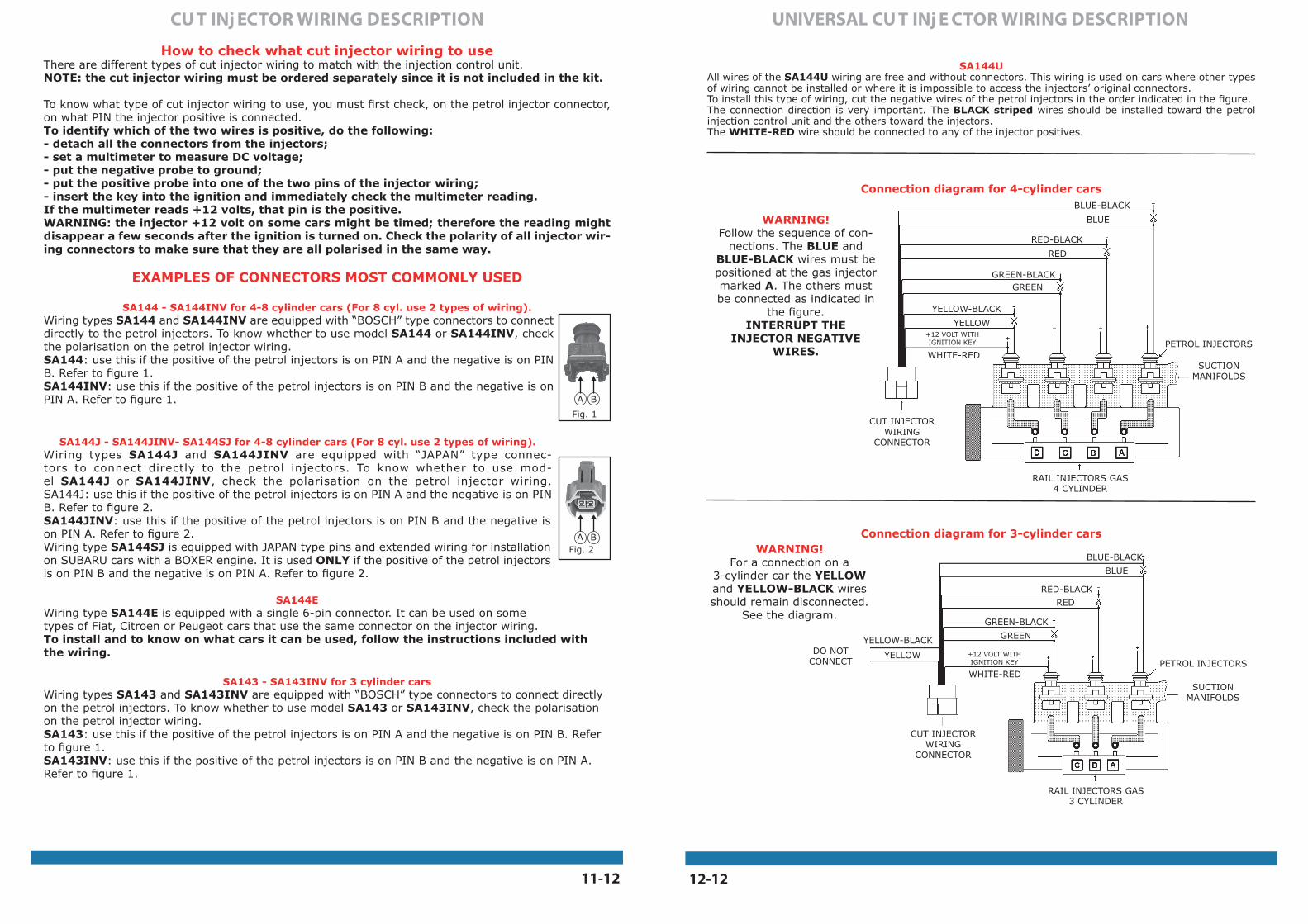
UNIVERSAL CU T INj E CTOR WIRING DESCRIPTION
PETROL INJECTORS
SUCTION MANIFOLDS
RAIL INJECTORS GAS 4 CYLINDER
CUT INJECTOR WIRING
CONNECTOR
PETROL INJECTORS
SUCTION MANIFOLDS
RAIL INJECTORS GAS 3 CYLINDER
BLUE-BLACK
BLUE
RED-BLACKRED
GREEN-BLACK
GREENYELLOW-BLACK
YELLOW
WHITE-RED
CUT INJECTOR WIRING
CONNECTOR
DO NOT CONNECT
BLUE-BLACK
BLUE
RED-BLACK
RED
GREEN-BLACKGREEN
YELLOW-BLACK
YELLOW
WHITE-RED
+12 VOLT WITH IGNITION KEY
SA144UAll wires of the SA144U wiring are free and without connectors. This wiring is used on cars where other types of wiring cannot be installed or where it is impossible to access the injectors’ original connectors.To install this type of wiring, cut the negative wires of the petrol injectors in the order indicated in the figure.The connection direction is very important. The BLACK striped wires should be installed toward the petrol injection control unit and the others toward the injectors.The WHITE-RED wire should be connected to any of the injector positives.
WARNING!Follow the sequence of con-
nections. The BLUE and BLUE-BLACK wires must be positioned at the gas injector marked A. The others must be connected as indicated in
the figure.INTERRUPT THE
INJECTOR NEGATIVE WIRES.
WARNING!For a connection on a
3-cylinder car the YELLOW and YELLOW-BLACK wires should remain disconnected.
See the diagram.
Connection diagram for 3-cylinder cars
Connection diagram for 4-cylinder cars
+12 VOLT WITH IGNITION KEY
How to check what cut injector wiring to useThere are different types of cut injector wiring to match with the injection control unit.NOTE: the cut injector wiring must be ordered separately since it is not included in the kit.
To know what type of cut injector wiring to use, you must first check, on the petrol injector connector, on what PIN the injector positive is connected.To identify which of the two wires is positive, do the following:- detach all the connectors from the injectors;- set a multimeter to measure DC voltage;- put the negative probe to ground;- put the positive probe into one of the two pins of the injector wiring;- insert the key into the ignition and immediately check the multimeter reading.If the multimeter reads +12 volts, that pin is the positive.WARNING: the injector +12 volt on some cars might be timed; therefore the reading might disappear a few seconds after the ignition is turned on. Check the polarity of all injector wir-ing connectors to make sure that they are all polarised in the same way.
EXAMPLES OF CONNECTORS MOST COMMONLY USED
SA144 - SA144INV for 4-8 cylinder cars (For 8 cyl. use 2 types of wiring).Wiring types SA144 and SA144INV are equipped with “BOSCH” type connectors to connect directly to the petrol injectors. To know whether to use model SA144 or SA144INV, check the polarisation on the petrol injector wiring.SA144: use this if the positive of the petrol injectors is on PIN A and the negative is on PIN B. Refer to figure 1.SA144INV: use this if the positive of the petrol injectors is on PIN B and the negative is on PIN A. Refer to figure 1.
SA144J - SA144JINV- SA144SJ for 4-8 cylinder cars (For 8 cyl. use 2 types of wiring).Wiring types SA144J and SA144JINV are equipped with “JAPAN” type connec-tors to connect directly to the petrol injectors. To know whether to use mod-el SA144J or SA144JINV, check the polarisation on the petrol injector wiring.SA144J: use this if the positive of the petrol injectors is on PIN A and the negative is on PIN B. Refer to figure 2.SA144JINV: use this if the positive of the petrol injectors is on PIN B and the negative is on PIN A. Refer to figure 2.Wiring type SA144SJ is equipped with JAPAN type pins and extended wiring for installation on SUBARU cars with a BOXER engine. It is used ONLY if the positive of the petrol injectors is on PIN B and the negative is on PIN A. Refer to figure 2.
SA144EWiring type SA144E is equipped with a single 6-pin connector. It can be used on some types of Fiat, Citroen or Peugeot cars that use the same connector on the injector wiring. To install and to know on what cars it can be used, follow the instructions included with the wiring.
SA143 - SA143INV for 3 cylinder carsWiring types SA143 and SA143INV are equipped with “BOSCH” type connectors to connect directly on the petrol injectors. To know whether to use model SA143 or SA143INV, check the polarisation on the petrol injector wiring.SA143: use this if the positive of the petrol injectors is on PIN A and the negative is on PIN B. Refer to figure 1.SA143INV: use this if the positive of the petrol injectors is on PIN B and the negative is on PIN A. Refer to figure 1.
Fig. 2BA
Fig. 1
BA
CU T INj ECTOR WIRING DESCRIPTION
12-1211-12